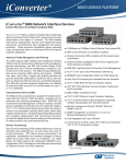
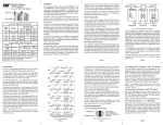
1
iConverter® Gx AN Media Converter
STANDALONE AND PLUG-IN MODULE
USER MANUAL
Table of Contents
1.0
1.1
2.0
2.1
2.1.1
3.0
3.1
3.2
3.2.1
3.3
3.4
4.0
4.1
4.2.1
5.0
6.0
6.1
6.1.1
6.1.2
6.1.3
7.0
Overview .................................................................................................................... 3
General Description .................................................................................................... 3
Port Structure ............................................................................................................. 4
Overview ..................................................................................................................... 4
UTP and Fiber Ports .................................................................................................. 4
Installation Procedure ................................................................................................ 5
Overview ..................................................................................................................... 5
Configuring DIP-switches ........................................................................................... 5
Board-Mounted DIP-switch Settings .......................................................................... 6
Installing the Module and Connecting Cables ............................................................ 8
Verifying Operation ................................................................................................... 10
Configuring the Module via Command Line Interface .............................................. 11
Overview ................................................................................................................... 11
SFP Status ............................................................................................................... 15
Gx AN Specifications ................................................................................................ 17
Troubleshooting Guide ............................................................................................. 18
Overview ................................................................................................................... 18
Power Issues ............................................................................................................ 18
Fiber Issues .............................................................................................................. 18
UTP Issues ............................................................................................................... 19
Warranty ................................................................................................................... 20
Page 2
1.0
OVERVIEW
This document describes the installation and configuration of the iConverter Gx AN standalone and plug-in
modules. The difference between the module types are indicated using the following legend throughout
this User Manual:
1.1
SA
- Standalone
PI
- Plug-In
GENERAL DESCRIPTION
The Omnitron iConverter® Gx AN provides 1000BASE-T UTP to 1000BASE-X Fiber media conversion.
The fiber optic port supports auto and forced negotiation configuration via DIP-switches. The UTP port
automatically detects and advertises the Duplex and Pause abilities of connected Gigabit fiber optic and
UTP devices.
The iConverter Gx AN models with fixed-fiber connectors are available with multimode (MM) dual-fiber,
single-mode (SM) dual-fiber and single-mode single-fiber (SF) options. They support ST, SC, LC and MTRJ connectors with distances up to 220/550m over MM fiber, 140km over SM fiber and 40km over SF.
The Gx AN Small Form Pluggable (SFP) model supports a wide variety of 1000BASE-X SFP transceivers
available.
The Gx AN plug-in module is a managed media converter when installed in a chassis with a management
module such as the Network Management Module (NMM) or the 10/100M2. The standalone module is an
unmanaged media converter supporting DIP-switches for configuration options.
IMPORTANT
This manual provides information on the installation and configuration of the module using the command
line interface (serial console). For ongoing network management, Omnitron Systems recommends
NetOutlook, an SNMP-based Network Management Software.
NetOutlook provides an efficient, user-friendly way to configure, monitor and manage devices installed
on a single network or on a series of networks by providing an intuitive graphical display with real-time
status and alarm (trap) information. The user can easily manage iConverter equipment on a large
Enterprise network or Metropolitan Area network (MAN) from a single location without the need of
additional resources.
The firmware of the Network Management Module (NMM) and NetOutlook must be at revision
3.3c or later to support the Gx AN plug-in module.
Page 3
2.0
PORT STRUCTURE
2.1
OVERVIEW
The front panel of the Gx AN provides access to the UTP and fiber ports. The fiber port will vary
depending on the connector type; ST, SC, MT-RJ, LC or SFP supporting 1000BASE-FX transceivers.
2.1.1
UTP and Fiber Ports
PI
SA
The fiber interface supports the 1000BASE-X protocol. The fiber interface operates in manual mode or
auto-negotiation and supports Full-Duplex operation.
The UTP Ethernet port supports 1000BASE-T protocols, auto-negotiation mode for Half and Full-Duplex.
When the fiber port is operating in manual mode, the UTP port can be manually forced to negotiate to a
specific duplex mode.
Page 4
3.0
INSTALLATION PROCEDURE
3.1
OVERVIEW
The following steps outline the installation and configuration procedures for the Gx AN. Refer to the
specified sections for detailed instructions.
• Configuring DIP-switches (Section 3.2)
• Installing the Module and Connecting Cables (Section 3.3)
• Verifying Operation (Section 3.4)
When the setup and configuration procedures are completed, the Gx AN has been configured with the basic
setup requirement for standard operation. To configure the module with additional features, see Section
4.0, “Detailed Module Configuration”.
3.2
CONFIGURING DIP-SWITCHES
PI
SA
The Gx AN plug-in module has two board-mounted DIP-switches. The standalone unit has one bank of
DIP-switches. The locations of the DIP-switches are illustrated below.
Switch 1
Bank 1
Switch 8
Left
Right
DIP-switch Locations
Page 5
3.2.1
Board-Mounted DIP-switch Settings
PI
SA
DIP-switch Bank 1 is available on both the plug-in and standalone modules. The table indicates the position
of the switch; Left/Down or Right/Up. As indicated in the DIP-switch location diagram, Left and Right
refers to the plug-in module and Down and Up refers to the standalone module.
PI
Switch
SW1
SW2
SW3
SW4
SW5
(Left/Right)
SA
Left/Down
(Factory Default)
P1 AN:
Port 1
Fiber Auto-Negotiation
P2 AN:
Port 2
UTP Auto-Negotiate
FDX:
Port 2
UTP Full-Duplex
OFF:
Port 2
Pause Disable
OFF:
Port 2
Asymmetric Pause Not
Advertised
(Up/Down)
Right/Up
P1 MAN:
Port 1
Fiber Manual Negotiation
P2 MAN:
Port 2
UTP Manual
HDX:
Port 2
UTP Half-Duplex
PAUSE:
Port 2
Pause Advertisement
Enable
ASYM:
Port 2
Asymmetric Pause
Advertistment
SW6 - SW8 See Link Mode DIP-switch Table in Section 3.2.1.4
3.2.1.1
SW1 - Port 1 Auto/Manual Negotiation “AN MAN”
When this DIP-switch is in the Auto-Negotiate “AN” position (factory default), the fiber optic port is
transparent to the network and allows the end devices connected to the module to advertise through the
module and establish negotiated settings between the end devices. If Port 2 (UTP) is not connected, the
fiber port will not be able to establish a fiber link. In the AN mode, the DIP-switches for Pause, Port 2
(UTP) and link modes RFD and SFD are ignored.
If two Gx AN modules are connected together and Port 1 is configured for Auto-Negotiation, the mode of
operation will be determined by the devices connected to Port 2 (UTP). Port 1 is transparent to the process.
When this DIP-switch is in the Manual “MAN” position, the advertised values of Port 2 is controlled by
DIP-switches SW2 through SW5.
3.2.1.2
SW2 and SW3 - Port 2 (UTP) Settings “AN MAN” “FDX HDX”
These DIP-switches are only valid when Port 1 is set to “MAN”. Port 2 is always set to Auto-Negotiation
and DIP-switch SW2 and SW3 only defines what modes are advertised. See Port 2 (UTP) Configuration
Matrix.
Page 6
PI
SA
SW2
SW3
Port 2 (UTP) Modes of Operation
AN
FDX
Configured for Auto Negotiation.
It advertises and negotiates in this order:
1000FDX, 1000HDX
AN
HDX
Configured for Auto Negotiation.
It advertises:
1000HDX
MAN
FDX
Configured for Forced Negotiation.
It advertises:
1000FDX
MAN
HDX
Configured for Forced Negotiation.
It advertises:
1000HDX
Port 2 (UTP) Configuration Matrix
3.2.1.3
SW4 and SW5 - Port 2 Pause Advertisement “OFF PAUSE” “OFF ASYM”
These DIP-switches are only valid when Port 1 is set to “MAN”. The PAUSE modes will be based on the
configuration of DIP-switches SW4 and SW5.
SW4
SW5
OFF
OFF
OFF
ASYM
PAUSE
OFF
PAUSE
ASYM
Port 2 (UTP) PAUSE Modes
No Pause advertised
Asymmetric PAUSE towards link partner
Symmetric PAUSE
Both Symmetric PAUSE and Asymmetric PAUSE
toward local device
Port 2 Pause Modes
Page 7
3.2.1.4
SW6, SW7, SW8 - Link Modes
These three DIP-switches configure the link mode settings. DIP-switch SW6 is valid when Port 1 is set to
“AN” or “MAN”. DIP-switches SW7 and SW8 are ignored when Port 1 is set to “AN”. The following
table details possible Link Mode DIP-switch configurations.
PI
SW1
SW6
SW7
SW8
Left
(AN)
Left
Left
Left
Left
(AN)
Right
Left
Left
Right
(MAN)
Left
Left
Left
Right
(MAN)
Right
Left
Left
Right
(MAN)
Left
Right
Left
Right
(MAN)
Right
Right
Right
(MAN)
Left
Right
(MAN)
SA
Result
SW1
SW6
SW7
SW8
Result
Enables Link Segment mode (LS).
Down
(AN)
Down
Down
Down
Enables Link Propagate mode (LP).
Down
(AN)
Up
Down
Down
Enables Link Segment mode (LS).
Up
(MAN)
Down
Down
Down
Enables Link Propagate mode (LP).
Up
(MAN)
Up
Down
Down
Enables Remote Fault Detection
mode plus Link Segment mode
(RFD+LS).
Up
(MAN)
Down
Up
Enables Remote Fault Detection
Down mode plus Link Segment mode
(RFD+LS).
Left
Enables Remote Fault Detection
mode plus Link Propagation mode
(RFD+LP).
Up
(MAN)
Up
Up
Enables Remote Fault Detection
Down mode plus Link Propagation mode
(RFD+LP).
Left
Right
Enables Symmetrical Fault Detect
mode (SFD).
Up
(MAN)
Down
Down
Up
Enables Symmetrical Fault Detect
mode (SFD).
Right
Left
Right
Illegal Setting, Link Segment (LS) is
selected.
Up
(MAN)
Up
Down
Up
Illegal Setting, Link Segment (LS) is
selected.
Right
(MAN)
Left
Right
Right
Illegal Setting, Link Segment (LS) is
selected.
Up
(MAN)
Down
Up
Up
llegal Setting, Link Segment (LS) is
selected.
Right
(MAN)
Right
Right
Right
Illegal Setting, Link Segment (LS) is
selected.
Up
(MAN)
Up
Up
Up
llegal Setting, Link Segment (LS) is
selected.
Enables Link Segment mode (LS).
Enables Link Propagate mode (LP).
Enables Link Segment mode (LS).
Enables Link Propagate mode (LP).
NOTE: Connecting two converters together where both are set to any of the RFD modes is illegal
and will cause a “deadly embrace” lockup.
NOTE: It is recommended to keep the LS setting (default) until initial configuration is complete.
For detailed information on the operation of the different Link Modes, download the application note
“iConverter Link Modes” available on Omnitron’s web page:
http://www.omnitron-systems.com/downloads.php
3.3
INSTALLING THE MODULE AND CONNECTING CABLES
PI
a.
Carefully slide the module into an open slot in the chassis. Align the module with the installation
guides and ensure that the module is firmly seated against the backplane. Secure the module by fastening
the front panel thumbscrew (push in and turn clockwise to tighten) to the chassis front. Verify the
“Pwr” LED is ON (indicating the chassis is powered).
SA
a.
The Gx AN standalone media converter is available in tabletop and wall-mounting models. For wallmounting, attach the Gx AN to a wall, backboard or other flat surfaces. For tabletop installation, place
the unit on a flat and level surface. Attach the rubber feet to the bottom of the Gx AN to prevent the
unit from sliding. Make sure the unit is placed in a safe, dry and secure location.
To power the unit using the AC/DC adapter, connect the AC/DC adapter to the AC outlet. Then
connect the barrel plug at the end of the wire on the AC/DC adapter to the 2.5mm DC barrel connector
(center-positive) on the unit. Confirm that the unit has powered up properly by checking the power
Page 8
status LED located on the front of the unit.
To power the unit using a DC power source, prepare a power cable using a two-conductor insulated
wire (not supplied) with a 14 AWG gauge minimum. Cut the power cable to the length required. Strip
approximately 3/8 of an inch of insulation from the power cable wires. Connect the power cables
to the standalone unit by fastening the stripped ends to the DC power connector.
Connect the power wires to the DC power source. The Power LED should indicate the presence of
power.
WARNING: Note the wire colors used in making the positive, negative and ground connections.
Use the same color assignment for the connection at the DC power source.
NOTE: If mounting with a safety ground attachment, use the safety ground screw at the rear of
the unit.
PI
b.
c.
d.
SA
When using a Gx AN SFP model, insert the SFP Fiber transceiver into the Port 1 SFP receptacle on the
Gx AN.
NOTE: The release latch of the SFP Fiber transceiver must be in the closed (up) position before
insertion.
Connect the UTP port via a Category 5 or better cable to a 1000BASE-T Ethernet device.
Connect the appropriate multimode or single-mode fiber cable to the fiber port of the installed module.
It is important to ensure that the transmit (TX) is attached to the receive side of the device at the other
end and the receive (RX) is attached to the transmit side. Single-fiber (SF) media converter models
operate in pairs. The TX wavelength must match the RX wavelength at the other end and the RX
wavelength must match the TX wavelength at the other end.
Page 9
3.4
VERIFYING OPERATION
PI
SA
Once the module has been installed and configured, per Sections 3.2 - 3.3, verify the module is operational
by viewing the status of the LED indicators. The table below provides a description for each LED indicator.
The Power LED indicates the module is receiving power from the chassis.
The Fiber Optic “FO” LED indicates the fiber optic connection between the modules has been established.
A blinking LED indicates the presence of data, an auto-negotiation problem or a link mode error indication.
The UTP LEDs indicate the module has established a connection across its UTP port. A blinking LED
indicates the presence of data.
Refer to Section 6.0, Troubleshooting Guide, for help in determining possible fault conditions.
PI
LED Function
"Legend"
Color
Power "Pwr"
Green No power
1000Mbps
Fiber Optics
"P1"
SA
Off State
PI
On / Blinking State
SA
On / Blinking State
On: Module has power
On: Module has power
On: Fiber Link
On: Fiber Link
Fast Blinking: Fiber Data Activity
Fast Blinking: Fiber Data Activity
Slow Blinking: Signal detect but
auto-negotiation has not completed
or SFD error detected
Slow Blinking: Signal detect but
auto-negotiation has not completed
or SFD error detected
On: UTP linked at 1000Mbps
On: UTP linked at 1000Mbps
Fast Blinking: UTP Data Activity
Fast Blinking: UTP Data Activity
Slow Blinking: SFD error detected
Slow Blinking: SFD error detected
On: Full-Duplex when any UTP link
is active
On: Full-Duplex when any UTP link
is active
Green No Fiber Link
Port 2 (UTP)
1000Mbps
"P2"
Green Not linked
Port 2 (UTP)
Full-Duplex
"FDX"
Half-Duplex when
Green any UTP link is
active
Page 10
4.0
CONFIGURING THE MODULE VIA COMMAND LINE INTERFACE
4.1
OVERVIEW
PI
SA
To configure the Gx AN, a Management Module (MM) must be installed in the same chassis. Configuration
of the module will be done through the serial management connection on the MM. Depending on the MM
installed in the chassis, the serial console port will either be a DB-9 female DCE or mini DIN-6 female
DCE interface. Attach the ends of a serial cable to the serial port of the PC and the Serial Console Port of
the NMM. This is a standard asynchronous serial interface.
Start HyperTerminal and select the correct COM Port in the HyperTerminal “Connect To:” window.
Set the PC’s serial port to the following:
Bits Per Second
57,600
Stop Bits
1
Data Bits
8
Parity
NONE
Hardware Flow Control
NONE
Power the chassis containing the MM and Gx AN modules and press <ENTER> to bring up a command
line prompt on the attached PC.
The MM may or may not have a password. If the MM does not have a password, the Password Entry
screen will be skipped and will go straight to the Management Options screen. If a password has been set,
the Password Entry screen will be displayed. Type the password and press <ENTER>, the Management
Module will respond with the Management Options screen.
PI
SA
Omnitron Systems Technology, Inc.
Copyright 2001-2007 OST, Inc.
iConverter, Serial Agent
Password Entry
-----------------------------------------------------------------------------Omnitron Systems Technology
Technical Support:
(949) 250-6510
140 Technology #500
Sales/Products:
(800) 675-8410
Irvine, CA 92618
On the web at:
www.omnitron-systems.com
-----------------------------------------------------------------------------IP Address
MAC
192.168.1.220
00:00:00:00:00:00
[xxxxxxxx]
Please enter the password >
Page 11
The Management Options screen will be displayed.
PI
SA
Management Options
iConverter, Serial Agent
Network Management
1: Chassis and Module Management
2: Set Module Identifier
Management Module Preferences
3: IP and Control Preferences
4: SNMP Preferences
5: Abandon Preference Changes
6: Save Preference Changes
7: Restore to Factory Defaults
8: Restart Management Module
9: Other Networking Features
Management Module Maintenance
10: Firmware Update
11: Set Date/Time
IP Address
= 192.168.1.220
Chassis Number = 1
Enter Choice, (H)elp, E(x)it >
The Gx AN can be configured from the Module configuration screen. The Module configuration screen is
accessible by selecting the module slot number from the Chassis View screen. To access the Module
configuration menu, select 1 at the Management Options screen, press <ENTER>. The Chassis Selection
screen will be displayed. From the Chassis Selection screen, select the chassis number where the Gx AN
module is installed.
NOTE: Module configuration is also available using NetOutlook.
PI
Chassis Selection
iConverter, Serial Agent
Number
Chassis Name
1
NMM
2
Not Available
3
Not Available
4
Not Available
5
Not Available
6
Not Available
7
Not Available
8
Not Available
9
Not Available
10
Not Available
11
Not Available
12
Not Available
13
Not Available
14
Not Available
15
Not Available
16
Not Available
17
Not Available
18
Not Available
19
Not Available
Connected to Chassis Number 1
Chassis Number(1-19), Management Options(0), (H)elp, E(x)it > 1
Page 12
By selecting Chassis Number 1, from the Chassis Selection screen, the Chassis View screen will be displayed.
PI
Chassis View 19 Slot
iConverter, Serial Agent
Chassis Number = 1
Slot
1
2
3
4
5
6
7
8
9
10
11
12
13
14
15
Model
8000-0
8903-1
8911-1
N/A
8500N-1
N/A
N/A
N/A
N/A
N/A
N/A
N/A
N/A
N/A
N/A
Type
NMM
10/100M
10/100M
Gx AN
|
|
|
|
|
|
|
|
|
|
|
|
|
|
|
|
Slot Model
16 N/A
17 N/A
18 N/A
19 N/A
20 N/A
21 8200-9
22 N/A
Type
Power Supply
Module to View(1-22), Chassis Selection(0), (R)eset, (H)elp, E(x)it > 5
SA
Chassis View 1 Slot
iConverter, Serial Agent
Chassis Number = 1
Slot
1
Model
8500N-1
Module to View(1),
Type
Gx AN
Module Identifier
Management Options(0), (R)eset, (H)elp, E(x)it >1
From the Chassis View menu, select the desired module (select 1 or 5), press <ENTER>. The Module
configuration screen will be displayed.
Page 13
PI
Module - iConverter Gx AN
Identifier Chassis Number
Slot Number
Model Number
= 19
= 13
= 8500N-0
Serial Number
Manufacturing Date
Product Revision
Software Revision
=
=
=
=
LED
1: Power
2: Not Available
3: Port 1 Link
4: Not Available
5: Not Available
6: Not Available
7: Not Available
8: Port 2 Duplex
9: Port 2 Link
iConverter, Serial Agent
xxxxxxxx
xxxxxxxx
xx
xx
= On
= On
= Off
= Off
Switch
1:
2:
3:
4:
5:
6:
7:
8:
ON Condition
Port 1 Manual
Port 2 Manual
Port 2 HDX
Pause Disable
Asym Pause
Link Propagate
Remote Fault
Symm Fault Det
OFF Condition
Port 1 AN
Port 2 AN
Port 2 FDX
Pause Enable
Sym Pause
Link Segment
Normal
Normal
H/W
Off
Off
Off
Off
Off
Off
Off
Off
Actual
Off
Off
Off
Off
Off
Off
Off
Off
Toggle Switch(1-8), (I)dentifier, (S)FP, (R)eset, (H)elp >
The Module configuration screen provides general information concerning the configuration and status of
the module. The screen displays the model and serial numbers, hardware and software revisions, as well as
the condition of the LEDs and DIP-switches. The DIP-switches can be re-configured (options 1 -8) without
removing the module from the chassis. Select the appropriate option to change the DIP-switch setting.
Selecting DIP-switch options 1 - 8, will cause the selection to change states under the ‘Actual’ heading.
Page 14
4.2.1
SFP Status
The Gx AN module installed with an SFP will provide general and specific information on the SFP. This
information is best viewed with SNMP management software. The following is the information available:
4.2.1.1
SFP A0 Information Display
This section displays fixed SFP Module information for the following areas.
•
Identifier Values
•
Extended Identifier
•
Connector Values
•
Transceiver Codes
•
Encoding Rules
•
Normal Bit Rate
•
Link Length
•
Vendor Name
•
Vendor OUI
•
Vendor Revision Number
•
Laser Wavelength
•
Options
•
Vendor Serial Number
•
Date Code
•
Diagnostic Monitoring Type
•
Enhanced Options
•
SFF-8472 Compliance
4.2.1.2
SFP A2 Information Display
This section displays decoded SFP data collected for the following statistics.
•
Measured Temperature
•
Measured Vcc
•
Measured Bias
•
Measured Tx Power
•
Measured Rx Power
•
Temperature High Alarm Setting
•
Temperature Low Alarm Setting
•
Temperature High Warning Setting
•
Temperature Low Warning Setting •
Vcc High Alarm Setting
•
Vcc Low Alarm Setting
•
Vcc High Warning Setting
•
Vcc Low Warning Setting
•
Bias High Alarm Setting
•
Bias Low Alarm Setting
•
Bias High Warning Setting
•
Bias Low Warning Setting
•
Tx Power High Alarm Setting
•
Tx Power Low Alarm Setting
•
Tx Power High Warning Setting
•
Tx Power Low Warning Setting
•
Rx Power High Alarm Setting
•
Rx Power Low Alarm Setting
•
Rx Power High Warning Setting
•
Rx Power Low Warning Setting
SFP status information can be obtained by selecting S from the Module configuration screen.
Page 15
PI
SA
SFP Statistics - iConverter Gx AN
Identifier Chassis Number = 1
Slot Number = 2
iConverter, Serial Agent
Model Number = 8500N-1
Port = 1
Address A0 Page Contents
===================================================
00: 03 04 07 00 10 02 00 00 00 00 00 01 03 00 14 C8 ................
10: 37 37 00 00 43 4F 52 45 54 45 4B 20 20 20 20 20 77..xxxxxxx
20: 20 20 20 20 00 00 00 00 43 54 2D 30 31 35 35 53
....xxxxxxxx
30: 53 50 2D 4D 42 35 4C 44 30 30 30 30 05 1E 00 84 xxxxxxxxxxxx....
40: 00 1A 00 00 41 31 36 37 45 43 35 30 30 30 30 30 ....A167EC500000
50: 36 20 20 20 30 35 31 32 30 37 20 20 68 90 01 A4 6
051207 h...
60: FF FF FF FF FF FF FF FF FF FF FF FF FF FF FF FF ................
70: FF FF FF FF FF FF FF FF FF FF FF FF FF FF FF FF ................
80: FF FF FF FF FF FF FF FF FF FF FF FF FF FF FF FF ................
90: FF FF FF FF FF FF FF FF FF FF FF FF FF FF FF FF ................
A0: FF FF FF FF FF FF FF FF FF FF FF FF FF FF FF FF ................
B0: FF FF FF FF FF FF FF FF FF FF FF FF FF FF FF FF ................
C0: FF FF FF FF FF FF FF FF FF FF FF FF FF FF FF FF ................
D0: FF FF FF FF FF FF FF FF FF FF FF FF FF FF FF FF ................
E0: FF FF FF FF FF FF FF FF FF FF FF FF FF FF FF FF ................
F0: FF FF FF FF FF FF FF FF FF FF FF FF FF FF FF FF ................
Enter Previous Screen(0), (n)ext page, (H)elp, E(x)it > n
SFP Statistics - iConverter Gx AN
Identifier Chassis Number = 1
Slot Number = 2
iConverter, Serial Agent
Model Number = 8500N-1
Port = 1
Address A2 Page Contents
===================================================
00: 64 00 F6 00 5A 00 FB 00 8C A0 75 30 88 B8 79 18 d...Z.....u0..y.
10: 9C 40 03 E8 88 B8 07 D0 09 D0 00 FB 07 CB 01 3C .@.............<
20: 18 A6 00 05 13 94 00 06 00 00 00 00 00 00 00 00 ................
30: 00 00 00 00 00 00 00 00 00 00 00 00 00 00 00 00 ................
40: 00 00 00 00 3F 80 00 00 00 00 00 00 01 00 00 00 ....?...........
50: 01 00 00 00 01 00 00 00 01 00 00 00 00 00 00 AE ................
60: 24 A8 80 78 17 14 03 F0 00 00 00 00 00 00 02 F8 $..x............
70: 00 40 00 00 00 40 00 00 00 00 00 00 00 00 00 00 .@...@..........
80: FF FF FF FF FF FF FF FF FF FF FF FF FF FF FF FF ................
90: FF FF FF FF FF FF FF FF FF FF FF FF FF FF FF FF ................
A0: FF FF FF FF FF FF FF FF FF FF FF FF FF FF FF FF ................
B0: FF FF FF FF FF FF FF FF FF FF FF FF FF FF FF FF ................
C0: FF FF FF FF FF FF FF FF FF FF FF FF FF FF FF FF ................
D0: FF FF FF FF FF FF FF FF FF FF FF FF FF FF FF FF ................
E0: FF FF FF FF FF FF FF FF FF FF FF FF FF FF FF FF ................
F0: FF FF FF FF FF FF FF FF FF FF FF FF FF FF FF FF ................
Enter Previous Screen(0), (b) previous page, (H)elp, E(x)it >
Page 16
5.0
GX AN SPECIFICATIONS
Plug-in Module
Description
Standalone Tabletop
Standalone Wall-Mount
1000BASE-T UTP to 1000BASE-X Fiber Media Converter
Protocols
1000BASE-T, 1000BASE-X with unlimited frame size
Cable Types
UTP
EIA/TIA 568A/B, Category 5 and higher
Fiber
Multimode: 50/125, 62.5/125, 100/140 um,
Single-mode: 9/125 um
Serial
RS-232, 22 to 24 AWG, 12 to 50 pF/ft.
Connector Types
UTP
RJ45
Fiber
SFP:
Dual Fiber:
Single Fiber:
LC
SC, ST, LC, MT-RJ
SC
Controls
DIP-switches and LEDs
Power Requirements
DC Power
0.7A @ 3.3VDC
Nominal: 0.3A @ 9.0VDC
Voltage Range: 8 - 15VDC
Power supplied by backplane
2.5mm Barrel Connector or Terminal Connector
AC Power Adapter [US]
N/A
120VAC/60Hz
0.04A @ 120VAC
AC Power Adapter [Int]
N/A
100-240VAC/50-60Hz
0.04A @ 120VAC
DC Power Connector
Dimensions
W: 0.85" x D: 4.5" x H: 2.8"
W: 3.1" x D: 4.8" x H: 1.0"
W: 3.8" x D: 4.8" x H: 1.0"
Weight
without power adapter
8 oz.
1 lb.
with power adapter
N/A
1.5 lb.
Compliance
UL, CE, FCC Class A
Temperature
Operational - Commercial
0 to +50oC
Operational - Wide Range
-40 to +60oC (-25oC Cold-Start Temperature)
-40 to +80oC
Storage
Humidity (non-condensing)
5 to 95%
Altitude (Operational)
-100m to 4,000m
MTBF [hrs]
without power adapter
with power adapter
870,000
1,100,000
N/A
250,000
Page 17
100,000
6.0
TROUBLESHOOTING GUIDE
6.1
OVERVIEW
The Gx AN module has several LED indicators available to assist in the determination of problems. Refer
to Section 3.3, Verify Operation, for LED definitions.
6.1.1
Power Issues
Problem:
The Power LED does not illuminate after installation is complete or no LED indicators are ON
Possible Causes:
A. For standalone modules, confirm that the power supply is connected to both the module and the AC or
DC power source. If Power LED is still not illuminated, use a voltmeter and check the voltage of the power
source (AC/DC converter used with the standalone unit should measure between 8 -15 VDC no load at the
barrel connector).
B. For plug-in module, confirm that the chassis is connected to an AC or DC power source. If the Power
LED is still not illuminated, remove the module and verify the operation of other modules in the chassis. If
power is present and the module will not turn ON, replace the module.
6.1.2
Fiber Issues
Problem:
The Fiber Optic link LED does not illuminate after installation is complete.
Possible Causes:.
A. Confirm that the UTP cable is connected properly to the iConverter Gx AN and the attached UTP
device.
B. Verify the Link Mode selection is set to Link Segment (LS). Until a stable link is established, leave the
Link Mode configured for LS. After a Link presence is established, the Link Mode selection can be modified.
C. Confirm that the fiber optic cable is properly connected to the iConverter Gx AN and the remote fiber
optic device. Connecting the fiber between the Tx of the far end to the Rx on the near end will cause the FO
LED on the near end to illuminate (only when the link mode is configured for Link Segment). Completing
the connection will cause the far end FO LED to illuminate.
D. Confirm that the fiber cable type matches the fiber transceiver type (multimode, single-mode) on the
iConverter Gx AN.
E. If using a dual-fiber model, confirm that the transmitter (Tx) is attached to the receiver side of its link
partner, and that the receiver (Rx) is attached to the transmitter. A optical power meter will assist in
determining which cable should be connected to the Tx and Rx of the module.
F. If using a single-fiber model, confirm that the Tx wavelength on the iConverter Gx AN matches the Rx
of the connected fiber optic device. Single-fiber units transmit and receive at different wavelengths (1510nm/
1310nm). Verify the model numbers to insure proper compatibility.
Problem:
The Fiber Optic link LED blinks slowly.
Possible Causes:
A. Auto-negotiation process has not completed. Check the end devices attached to Port 2 (UTP) for
consistent settings.
B. Make sure Port 2 (UTP) is connected to a 1000M only switch port.
Page 18
6.1.3
UTP Issues
Problem:
The UTP link LED does not illuminate after installation is complete.
Possible Causes:
A. Confirm that the UTP cable is connected properly to the iConverter Gx AN and the attached UTP
device. Once a connection has been established between the iConverter and its link partner (switch or
workstation), the corresponding Port 2 (P2) LED should illuminate. If the LED does not illuminate, check
the Link Mode configuration. A link mode other than Link Segment may cause the P2 LED not to turn ON.
B. Verify the iConverter Gx AN Port 2 (UTP) is connected to 1000Mbps switch or workstation port. The
module does not support 10/100Mbps.
C. Verify the distance between the iConverter and the link partner is within 100 meters.
D. Confirm that the UTP cable pin-out is correct (EIA/TIA-568-A). The module has auto-crossover
capability, so it will accept either a straight-through or crossover cable.
NOTE: If corrective actions do not resolve your situation, please contact Omnitron Systems Technical
Support.
Page 19
7.0
WARRANTY
This product is warranted to the original purchaser against defects in material and workmanship for a
period of TWO YEARS from the date of shipment. A LIFETIME warranty may be obtained by the original
purchaser by REGISTERING this product with Omnitron within 90 days from the date of shipment. TO
REGISTER, COMPLETE AND MAIL OR FAX THE ENCLOSED REGISTRATION FORM TO THE
INDICATED ADDRESS. Or you may register your product on the Internet at http://www.omnitronsystems.com. During the warranty period, Omnitron will, at its option, repair or replace a product which is
proven to be defective.
For warranty service, the product must be sent to an Omnitron designated facility, at Buyer’s expense.
Omnitron will pay the shipping charge to return the product to Buyer’s designated US address using
Omnitron’s standard shipping method.
Limitation of Warranty
The foregoing warranty shall not apply to defects resulting from improper or inadequate use and/or
maintenance of the equipment by Buyer, Buyer-supplied equipment, Buyer-supplied interfacing, unauthorized
modifications or
tampering with equipment (including removal of equipment cover by personnel not specifically authorized
and certified by Omnitron), or misuse, or operating outside the environmental specification of the product
(including but not limited to voltage, ambient temperature, radiation, unusual dust, etc.), or improper site
preparation or maintenance.
No other warranty is expressed or implied. Omnitron specifically disclaims the implied warranties of
merchantability and fitness for any particular purpose.
Exclusive Remedies
The remedies provided herein are the Buyer’s sole and exclusive remedies. Omnitron shall not be liable for
any direct, indirect, special, incidental, or consequential damages, whether based on contract, tort, or any
legal theory.
Technical Support
140 Technology Dr. #500
Irvine, CA 92618
949-250-6510 tel
949-250-6514 fax
email: support@omnitron-systems.com
web: www.omnitron-systems.com
041-8500N-001A 10/07
Page 20