1
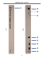
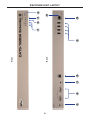
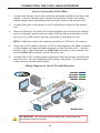
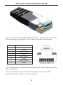
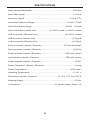
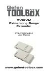
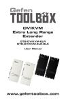
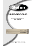
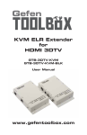
®
CAT5-1600A
Extender
EXT-CAT5-1600A
User Manual
www.gefen.com
ASKING FOR ASSISTANCE
Technical Support:
Telephone
Fax
(818) 772-9100
(800) 545-6900
(818) 772-9120
Technical Support Hours:
8:00 AM to 5:00 PM Monday thru Friday Pacific Time
Write To:
Gefen LLC
c/o Customer Service
20600 Nordhoff St
Chatsworth, CA 91311
www.gefen.com
support@gefen.com
Notice
Gefen LLC reserves the right to make changes in the hardware, packaging and
any accompanying documentation without prior written notice.
CAT5-1600A Extender is a trademark of Gefen LLC
© 2011 Gefen LLC, All Rights Reserved
All trademarks are the property of their respective owners
Rev A5
CONTENTS
1
Introduction
2
Operation Notes
3
Features
4
Sender Unit Layout
5
Sender Unit Descriptions
6
Receiver Unit Layout
7
Receiver Unit Descriptions
8
Connecting the CAT5-1600A Extender
9
DIP Switch Configuration
12 Network Cable Wiring Diagram
13 Specifications
14 Warranty
INTRODUCTION
Congratulations on your purchase of the CAT5-1600A Extender. Your complete
satisfaction is very important to us.
Gefen
Gefen is a unique product line catering to the growing needs for innovative home
theater solutions. We specialize in total integration for your home theater, while
also focusing on going above and beyond customer expectations to ensure you
get the most from your hardware. We invite you to explore our distinct product
line and hope you find your solutions. Please call us so we can better assist you
with your particular needs.
The Gefen CAT5-1600A Extender
The Gefen CAT5-1600A extends VGA and Audio up to 1000 feet (300 meters)
and USB up to 330 feet (100 meters) using CAT-5 cables. Display resolutions up
to 1920 x 1200 are supported. A local monitor can be connected to the Sender
Unit and up to two monitors can be connected to the Receiver Unit. Four USB
connectors on the Receiver Unit allow control of the computer system from the
KVM workstation. Mini-stereo connectors provide for the connection and the
extension of audio devices.
How It Works
Place the CAT5-1600A Sender Unit next to the VGA source. Use the included
VGA cable to connect the source to the Sender Unit. Optionally connect a local
monitor to the Sender Unit using a VGA cable. Connect up to two monitors to the
Receiver Unit with VGA cables. Connect the USB devices to the input and output
connectors. For audio, connect a mini-stereo cable between the audio source
and the audio input on the Sender Unit. Connect a mini-stereo cable between
the audio output on the Receiver Unit and the audio device. Use two CAT-5
cables to connect the Sender Unit to the Receiver Unit. VGA and Audio can be
extended to 1000 feet (300 meters). USB is extended over a separate CAT-5
cable up to 330 feet (100 meters). Connect the included locking power supplies
to both the Sender Unit and Receiver Unit then connect both power cables to
available electrical outlets. The computer can now be controlled from the KVM
workstation.
1
OPERATION NOTES
READ THESE NOTES BEFORE
OPERATING THE CAT5-1600A EXTENDER
•
The CAT5-1600A extends VGA and Audio up to 1000 feet (300 meters).
•
CAT-5 cables should not exceed 330 feet (100 meters) when extending
USB.
2
FEATURES
Features
•
Extends any VGA and Audio device up to 1000 feet (300 meters)
•
Extends USB devices up to 330 feet (100 meters)
•
Supports resolutions up to 1920x1200@60Hz
•
Local and Pass-Through EDID Modes
•
Supports USB 2.0
•
Backward-compatible with USB 1.1 devices
•
Color, Brightness, and Focus controls to compensate for the extension
distance and skew variations found in different CAT-5 cabling.
•
Standby Mode for reduced power consumption when a VGA source is not
detected.
•
Locking Power Connectors
•
Mounting Brackets
Package Includes
(1) CAT5-1600A - Sender Unit
(1) CAT5-1600A - Receiver Unit
(1) 6 ft. VGA Cable (M-F)
(1) 6 ft. USB Cable (A-B)
(1) 6 ft. Mini-Stereo Cable (3.5 mm)
(2) 5V DC Locking Power Supplies
(1) Set of Rack Ears
(1) User Manual
3
2
3
4
5
6
Back
Front
7
8
9
1
SENDER UNIT LAYOUT
4
SENDER UNIT DESCRIPTIONS
1
Power Indicator
This LED will turn RED once the locking power supply has been properly
connected. When the CAT-5 link is established between the Sender and
Receiver units, the LED will be GREEN. When the Sender unit is in Standby
Mode or Power Saving Mode, this LED will be RED. (Power Saving Mode is
covered in detail on page 9).
2
5V DC Locking Power Connector
Connects the included 5V DC Locking Power Supply to this receptacle.
3
VGA Input (HD15 Connector)
Connect the VGA source to this port.
4
Local Monitor Output (HD15 Connector)
Connect a VGA monitor to this port.
5
Audio Input Connector (3.5mm Mini-Stereo)
Connect analog audio here via a 3.5 mm audio jack.
6
CAT-5 Video Output Jack (RJ-45 Connector)
Connects the Sender unit to the Receiver Unit using CAT-5 cable. Used to
extend the video signal to the Receiver Unit.
7
USB Input Port (USB type “B”)
Connect a Computer or USB device to this port.
8
Host Indicator
This LED will turn GREEN when the power and all devices are connected to
the Sender unit. The LED will turn RED if a USB device or monitor has been
disconnected from the Sender unit.
9
CAT-5 USB Link Output (RJ-45 Connector)
Connects the Sender unit to the Receiver unit using CAT-5 cable. Used to
extend the USB device from the Sender Unit to the Receiver Unit.
5
5
6
7
8
Back
Front
9
1
2
10
3
11
4
RECEIVER UNIT LAYOUT
6
RECEIVER PANEL DESCRIPTIONS
1
RGB Equalization Trim Pots (Trim Potentiometers)
Adjusts the Red, Green, and Blue color components to correct color
convergence / divergence due to varying distances and/or skew variations found
in different brands of CAT-5 cable. Turn the controls to achieve the best color
and picture. See page 11 for details.
Note:: When turning the Trim Pots, use a small screwdriver or an electronic
device adjustment tool (available at electronics stores). Use gentle force when
rotating Trim Pot controls. Turn controls in both directions if necessary to get
best results. Never force a control if resistance is encountered. Gefen is not
responsible for inoperable units due to broken trim pot controls.
2
Brightness Trim Pot
Adjusts the brightness of the picture.
3
Focus Trim Pot
Adjusts the focus of the picture.
4
Power Indicator LED
This LED will turn RED once the locking power supply has been properly
connected. When the CAT-5 link is established, the LED will be GREEN. When
the Receiver unit is in Standby Mode or Power Saving Mode, this LED will be
RED. (Power Saving Mode is covered in detail on page 9).
5
5V DC Locking Power Connector (threaded jack on rear left of Receiver)
Connects the included 5V DC Locking Power Supply here. Screw in the locking
power connector with hand force only until it stops turning. Do not overtighten.
6
VGA Outputs (2 x HD15 Connectors)
Connect VGA monitors to these ports.
7
Audio Output Connector (3.5mm Mini-Stereo)
Connect the audio from this port to an analog audio amplifier.
8
CAT-5 Video Link Input (RJ-45 Connector)
Connects the Sender unit to the Receiver unit using CAT-5 cable. Used to
receive the video signal from the Sender Unit.
9
USB Ports (4 x USB 2.0 type “A”)
Connect the USB devices (keyboard, mouse device, etc.) to these ports. The
CAT5-1600A Receiver functions as a 4-port USB 2.0 Hub.
10 CAT-5 USB Link Input (RJ-45 Connector)
Receives the USB signals from the Sender Unit. Connects to the Receiver unit
via a length of CAT-5 cabling.
11 Host Indicator
This LED will turn GREEN when the power and all devices are connected to
the Sender unit. The LED will turn RED if a USB device or monitor has been
disconnected from the Sender unit.
7
CONNECTING THE CAT5-1600A EXTENDER
How to Connect the CAT5-1600A
1.
Connect the Sender Unit to the computer using the included VGA and USB
cables. If audio is being used, connect the included 3.5mm mini-stereo
cable between the audio source and the audio input on the Sender Unit.
2.
Connect the local VGA monitor to the Local Monitor output on the Sender
Unit.
3.
Place the Receiver Unit near the KVM workstation and connect the display,
mouse, keyboard, printer and any other USB devices to the Receiver Unit.
Up to four (4) USB devices can be connected to the Receiver Unit.
NOTE: USB has a maximum extension distance of 330 feet (100 meters).
4.
Using two CAT-5 cables, connect a CAT-5 cable between the Link connector
on the Sender Unit and the Link connector on the Receiver Unit. Connect
another CAT-5 cable between the USB Link connector on the Sender Unit
and the USB Link connector on the Receiver Unit.
5.
Connect the 5V DC locking power supplies to both the Sender Unit and the
Receiver Unit. Do not overtighten the locking connectors. Plug the power
cords into any available wall outlets.
Wiring Diagram for the CAT5-1600A Extender
VGA CABLE
CAT-5 CABLE
AUDIO CABLE
USB CABLE
Computer
(Up To 1,000 feet)
Receiver
Powered
Speakers
Local VGA Monitor
Sender
USB Mouse
VGA Monitor
USB Keyboard
VGA Monitor
USB External HDD
USB Printer
EXT-CAT5-1600A
ATTENTION: This product should always be connected to a
grounded electrical socket.
8
DIP SWITCH CONFIGURATION
Sender Unit
The CAT5-1600A contains two (2) DIP switches on the bottom of the Sender Unit
and the Receiver Unit. The follow information outlines the functionality of each
DIP switch:
The two DIP switches on the
bottom of the Sender Unit.
DIP Switch 1 - Green Mode (Default = ON)
•
OFF
F - Enable Green Mode
If DIP switch 1 is set to the OFF position, then the product is will be placed
in “Green Mode”. This means that the unit will not power the USB if the USB
cable from the Sender to the computer source is disconnected. In “Green
Mode”, the product consumes less than 1 watt of power.
•
ON
N - Disable Green Mode
When DIP switch 1 on the Sender Unit is set to the ON position, “Green
Mode” is disabled. This means that the USB is always powered whether or
not there is a signal. This mode will allow the computer to wake up when it
is placed in sleep mode.
DIP Switch 2 - Not Used
•
Reserved for future expansion.
NOTE: DIP switch 1 on both the Sender Unit and the Receiver Unit
must be set to the OFF position in order to operate in “Green Mode”.
9
DIP SWITCH CONFIGURATION
Receiver Unit
The CAT5-1600A Receiver Unit contains two (2) DIP switches on the bottom of
the unit. A single trim pot (potentiometer) is also located next to the DIP switch
bank. The follow information outlines the functionality of each DIP switch and the
trim pot:
The two DIP switches and single
trim pot on the bottom of the
Receiver Unit.
DIP Switch 1 - Green Mode (Default = ON)
•
OFF
F - Enable Green Mode
If DIP switch 1 is set to the OFF position, then the product is will be placed
in “Green Mode”. This means that the unit will not power the USB if the USB
cable from the Sender to the computer source is disconnected. In “Green
Mode”, this product consumes less than 1 watt of power.
•
ON
N - Disable Green Mode
When DIP switch 1 is set to the ON position, “Green Mode” is disabled. This
means that the USB is always powered whether or not there is a signal.
This mode will allow the computer to wake up when it is placed in sleep
mode.
NOTE: DIP switch 1 on both the Sender Unit and the Receiver Unit
must be set to the OFF position in order to operate in “Green Mode”.
10
DIP SWITCH CONFIGURATION
DIP Switch 2 - EDID Mode (Default = OFF)
•
OFF
F - Pass-Through Mode
If DIP switch 2 is OFF, then the downstream EDID information is copied to
the input.
•
ON
N - Local EDID
When DIP switch 2 is set to the ON position, then the EDID is copied from
the Local Monitor output on Sender Unit.
Trim Pot - Pole Frequency
This trim pot is used to adjust the brightness and focus of the picture.
1.
Insert a small flat-headed tool into the EQ trim pot located on the bottom of
the Receiver Unit.
2.
The trim pot has 8 set positions. Turn the trim pot clockwise until it clicks into
the next position. Continue adjusting the trim pot until the issue is resolved.
3.
Carefully remove the adjustment tool.
11
NETWORK CABLE WIRING DIAGRAM
Gefen recommends the TIA/EIA-568-B wiring option. Please adhere to the table
below when field-terminating the CAT-5 cable for use with Gefen products.
Pin
Color
1
Orange / White
2
Orange
3
Green / White
4
Blue
5
Blue / White
6
Green
7
Brown / White
8
Brown
12345678
CAT-5 cabling comes in stranded and solid core types. Gefen recommends using
solid core cabling.
It is recommended to use one continuous run from one end to the other.
Connecting through a patch is not recommended.
12
SPECIFICATIONS
Video Amplifier Bandwidth ....................................................................... 350 MHz
Input Video Signal.....................................................................................1.2 V p-p
Input Sync Signal............................................................................... 5 V p-p (TTL)
Horizontal Frequency Range ........................................................ 15 kHz - 70 kHz
Vertical Frequency Range .......................................................... 30 kHz - 170 kHz
VGA Connectors (Sender Unit) ...................... (1) HD-15, male; (1) HD-15, female
VGA Connectors (Receiver Unit) ............................................... (2) HD-15, female
USB Connector (Sender Unit) ............................................................... (1) Type B
USB Connectors (Receiver Unit) ........................................................... (4) Type A
Audio Connector (Sender / Receiver) ..................................... 3.5 mm mini-stereo
Link Connectors (Sender / Receiver) ...................................................... (2) RJ-45
Power Indicator (Sender / Receiver)............................................LED (red / green)
Host Indicator (Sender / Receiver) ............................................. LED (red / green)
Power Supplies (Sender / Receiver) ........................................................... 5V DC
Power Connectors (Sender / Receiver) .................................................... Locking
Power Consumption ........................................................................... 30 W (max.)
Operating Temperature .............................................................................0 - 40 °C
Dimensions (Sender / Receiver) ....................................17” W x 1.75” H x 5.25” D
Shipping Weight...........................................................................................5.0 lbs.
Certifications.............................................................UL (power supply), RoHS, CE
13
WARRANTY
Gefen warrants the equipment it manufactures to be free from defects in material
and workmanship.
If equipment fails because of such defects and Gefen is notified within two (2)
years from the date of shipment, Gefen will, at its option, repair or replace the
equipment, provided that the equipment has not been subjected to mechanical,
electrical, or other abuse or modifications. Equipment that fails under conditions
other than those covered will be repaired at the current price of parts and labor in
effect at the time of repair. Such repairs are warranted for ninety (90) days from
the day of reshipment to the Buyer.
This warranty is in lieu of all other warranties expressed or implied, including
without limitation, any implied warranty or merchantability or fitness for any
particular purpose, all of which are expressly disclaimed.
1.
Proof of sale may be required in order to claim warranty.
2.
Customers outside the US are responsible for shipping charges to and from
Gefen.
3.
Copper cables are limited to a 30 day warranty and cables must be in their
original condition.
The information in this manual has been carefully checked and is believed to
be accurate. However, Gefen assumes no responsibility for any inaccuracies
that may be contained in this manual. In no event will Gefen be liable for
direct, indirect, special, incidental, or consequential damages resulting from
any defect or omission in this manual, even if advised of the possibility of such
damages. The technical information contained herein regarding the features and
specifications is subject to change without notice.
For the latest warranty coverage information, refer to the Warranty and Return
Policy under the Support section of the Gefen Web site at www.gefen.com.
PRODUCT REGISTRATION
Please register your product online by visiting the Register Product page
under the Support section of the Gefen Web site.
14
Rev A5
20600 Nordhoff St., Chatsworth CA 91311
1-800-545-6900
818-772-9100
www.gefen.com
Pb
This product uses UL listed power supplies.
fax: 818-772-9120
support@gefen.com