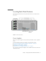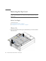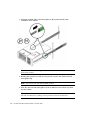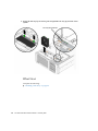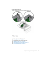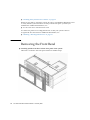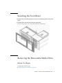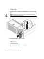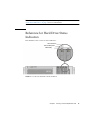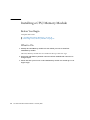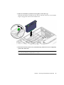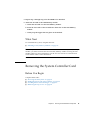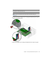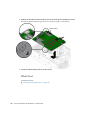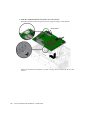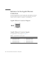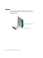
1
Sun Fire™ V445 Server
Service Manual
Sun Microsystems, Inc.
www.sun.com
Part No. 819-3742-11
February 2007, Revision A
Submit comments about this document at: http://www.sun.com/hwdocs/feedback
Copyright 2007 Sun Microsystems, Inc., 4150 Network Circle, Santa Clara, California 95054, U.S.A. All rights reserved.
Sun Microsystems, Inc. has intellectual property rights relating to technology that is described in this document. In particular, and without
limitation, these intellectual property rights may include one or more of the U.S. patents listed at http://www.sun.com/patents and one or
more additional patents or pending patent applications in the U.S. and in other countries.
This document and the product to which it pertains are distributed under licenses restricting their use, copying, distribution, and
decompilation. No part of the product or of this document may be reproduced in any form by any means without prior written authorization of
Sun and its licensors, if any.
Third-party software, including font technology, is copyrighted and licensed from Sun suppliers.
Parts of the product may be derived from Berkeley BSD systems, licensed from the University of California. UNIX is a registered trademark in
the U.S. and in other countries, exclusively licensed through X/Open Company, Ltd.
Sun, Sun Microsystems, the Sun logo, Java, docs.sun.com, OpenBoot, Sun Fire, and Solaris are trademarks or registered trademarks of Sun
Microsystems, Inc. in the U.S. and in other countries.
All SPARC trademarks are used under license and are trademarks or registered trademarks of SPARC International, Inc. in the U.S. and in other
countries. Products bearing SPARC trademarks are based upon an architecture developed by Sun Microsystems, Inc.
The OPEN LOOK and Sun™ Graphical User Interface was developed by Sun Microsystems, Inc. for its users and licensees. Sun acknowledges
the pioneering efforts of Xerox in researching and developing the concept of visual or graphical user interfaces for the computer industry. Sun
holds a non-exclusive license from Xerox to the Xerox Graphical User Interface, which license also covers Sun’s licensees who implement OPEN
LOOK GUIs and otherwise comply with Sun’s written license agreements.
U.S. Government Rights—Commercial use. Government users are subject to the Sun Microsystems, Inc. standard license agreement and
applicable provisions of the FAR and its supplements.
DOCUMENTATION IS PROVIDED "AS IS" AND ALL EXPRESS OR IMPLIED CONDITIONS, REPRESENTATIONS AND WARRANTIES,
INCLUDING ANY IMPLIED WARRANTY OF MERCHANTABILITY, FITNESS FOR A PARTICULAR PURPOSE OR NON-INFRINGEMENT,
ARE DISCLAIMED, EXCEPT TO THE EXTENT THAT SUCH DISCLAIMERS ARE HELD TO BE LEGALLY INVALID.
Copyright 2007 Sun Microsystems, Inc., 4150 Network Circle, Santa Clara, Californie 95054, États-Unis. Tous droits réservés.
Sun Microsystems, Inc. possède les droits de propriété intellectuels relatifs à la technologie décrite dans ce document. En particulier, et sans
limitation, ces droits de propriété intellectuels peuvent inclure un ou plusieurs des brevets américains listés sur le site
http://www.sun.com/patents, un ou les plusieurs brevets supplémentaires ainsi que les demandes de brevet en attente aux les États-Unis et
dans d’autres pays.
Ce document et le produit auquel il se rapporte sont protégés par un copyright et distribués sous licences, celles-ci en restreignent l’utilisation,
la copie, la distribution, et la décompilation. Aucune partie de ce produit ou document ne peut être reproduite sous aucune forme, par quelque
moyen que ce soit, sans l’autorisation préalable et écrite de Sun et de ses bailleurs de licence, s’il y en a.
Tout logiciel tiers, sa technologie relative aux polices de caractères, comprise, est protégé par un copyright et licencié par des fournisseurs de
Sun.
Des parties de ce produit peuvent dériver des systèmes Berkeley BSD licenciés par l’Université de Californie. UNIX est une marque déposée
aux États-Unis et dans d’autres pays, licenciée exclusivement par X/Open Company, Ltd.
Sun, Sun Microsystems, le logo Sun, Java, docs.sun.com, OpenBoot, Sun Fire, et Solaris sont des marques de fabrique ou des marques déposées
de Sun Microsystems, Inc. aux États-Unis et dans d’autres pays.
Toutes les marques SPARC sont utilisées sous licence et sont des marques de fabrique ou des marques déposées de SPARC International, Inc.
aux États-Unis et dans d’autres pays. Les produits portant les marques SPARC sont basés sur une architecture développée par Sun
Microsystems, Inc.
L’interface utilisateur graphique OPEN LOOK et Sun™ a été développée par Sun Microsystems, Inc. pour ses utilisateurs et licenciés. Sun
reconnaît les efforts de pionniers de Xerox dans la recherche et le développement du concept des interfaces utilisateur visuelles ou graphiques
pour l’industrie informatique. Sun détient une license non exclusive de Xerox sur l’interface utilisateur graphique Xerox, cette licence couvrant
également les licenciés de Sun implémentant les interfaces utilisateur graphiques OPEN LOOK et se conforment en outre aux licences écrites de
Sun.
LA DOCUMENTATION EST FOURNIE "EN L’ÉTAT" ET TOUTES AUTRES CONDITIONS, DÉCLARATIONS ET GARANTIES EXPRESSES
OU TACITES SONT FORMELLEMENT EXCLUES DANS LA LIMITE DE LA LOI APPLICABLE, Y COMPRIS NOTAMMENT TOUTE
GARANTIE IMPLICITE RELATIVE À LA QUALITÉ MARCHANDE, À L’APTITUDE À UNE UTILISATION PARTICULIÈRE OU À
L’ABSENCE DE CONTREFAÇON.
Contents
Preface
1.
xix
Identifying Front Panel and
Back Panel Features 1
Locating Front Panel Features
Front Panel Indicators
Power Button
USB Ports
2
3
5
6
SAS Hard Drives
7
Removable Media Drive
8
Locating Back Panel Features
Power Supplies
PCI Slots
9
9
10
System Controller Ports
11
Network Management Port
Serial Management Port
System I/O Ports
USB Ports
11
12
12
12
Gigabit Ethernet Ports
DB-9 Serial Port
13
13
iii
System Status Indicators
2.
14
Preparing to Service the System
Service Guidelines
15
16
Tools Required for Installation and Service
Powering On the System
Before You Begin
What to Do
17
What Next
18
17
Powering Off the System
Before You Begin
What to Do
18
What Next
19
17
18
18
Initiating a Reconfiguration Boot
Before You Begin
What to Do
20
What Next
21
19
19
Sliding the Server Out of the Cabinet
Before You Begin
What to Do
23
What Next
25
22
Sliding the Server Into the Cabinet
Before You Begin
What to Do
26
What Next
27
26
Removing the Top Cover
Before You Begin
iv
What to Do
28
What Next
29
28
28
Sun Fire V445 Server Service Manual • February 2007
26
22
16
Installing the Top Cover
Before You Begin
What to Do
29
What Next
30
29
29
Removing the Server From the Cabinet
Before You Begin
What to Do
31
What Next
36
31
Installing the System Into the Cabinet
Before You Begin
What to Do
37
What Next
40
3.
What to Do
41
What Next
43
36
36
Avoiding Electrostatic Discharge
Before You Begin
30
41
41
Servicing Customer-Replacable Units
45
About Hot-Pluggable and Hot-Swappable Components
About the Fan Trays
46
Removing a Fan Tray
47
Before You Begin
47
What to Do
47
What Next
48
Installing a Fan Tray
49
Before You Begin
49
What to Do
49
What Next
50
46
Removing a Hard Drive
51
Contents
v
Before You Begin
What to Do
51
What Next
52
Installing a Hard Drive
Before You Begin
What to Do
53
What Next
54
51
53
53
Removing a Hard Drive Using
a Hot-Plug Operation 55
Before You Begin
What to Do
56
What Next
56
55
Installing a Hard Drive Using the Hot-Plug Operation
Before You Begin
What to Do
58
What Next
58
57
Removing a Power Supply
Before You Begin
What to Do
59
What Next
60
59
Installing a Power Supply
Before You Begin
What to Do
60
60
61
Removing a PCI Card
Before You Begin
vi
58
What to Do
62
What Next
65
62
62
Installing a PCI Card
66
Before You Begin
66
Sun Fire V445 Server Service Manual • February 2007
57
What to Do
66
What Next
69
Removing the Front Bezel
Installing the Front Bezel
70
71
Removing the Removable Media Drive
Before You Begin
What to Do
72
What Next
72
71
Installing the Removable Media Drive
Before You Begin
What to Do
73
What Next
74
71
73
73
Reference for Fan Tray Status Indicators
74
Reference for Hard Drive Status Indicators
75
Reference for Power Supply Status Indicators
4.
Servicing the Motherboard Components
About Predictive Self-Healing
About the DIMMs
Configuration Rules
About the IDPROM
80
82
82
82
Removing a CPU/Memory Module
Before You Begin
84
What Next
85
Before You Begin
83
83
Installing a CPU/Memory Module
What to Do
79
80
Memory Interleaving
What to Do
76
86
86
86
Contents
vii
What Next
88
Removing a DIMM
89
Before You Begin
What to Do
89
What Next
91
Installing a DIMM
92
Before You Begin
What to Do
92
What Next
93
89
92
Removing the System Controller Card
Before You Begin
What to Do
94
What Next
95
93
Installing the System Controller Card
Before You Begin
What to Do
96
What Next
97
What to Do
98
What Next
99
Installing the IDPROM
Before You Begin
What to Do
99
What Next
100
96
96
Removing the IDPROM
Before You Begin
93
98
98
99
99
Removing the System Controller Battery
Before You Begin
What to Do
viii
100
101
Sun Fire V445 Server Service Manual • February 2007
100
What Next
101
Installing the System Controller Battery
Before You Begin
What to Do
101
What Next
102
101
101
Removing the CPU/Memory Module Bracket
Before You Begin
What to Do
102
What Next
103
102
Installing the CPU/Memory Module Bracket
Before You Begin
What to Do
104
What Next
105
What to Do
106
What Next
108
5.
What to Do
109
What Next
112
106
106
Installing the Motherboard
Before You Begin
109
109
Servicing Miscellaneous Components
Removing the Motherboard Fan Cage
Before You Begin
What to Do
114
What Next
115
113
114
114
Installing the Motherboard Fan Cage
Before You Begin
104
104
Removing the Motherboard
Before You Begin
102
115
115
Contents
ix
What to Do
115
What Next
116
Removing the Front I/O Board
Before You Begin
What to Do
117
What Next
118
117
Installing the Front I/O Board
Before You Begin
What to Do
119
What Next
120
117
119
119
Removing the Front Indicator Board
Before You Begin
What to Do
122
What Next
123
121
Installing the Front Indicator Board
Before You Begin
What to Do
124
What Next
125
121
123
123
About the Data Cable Connector Board/SAS Controller Configurations
Removing the Multilane Data Cable Connector Board
Before You Begin
What to Do
127
What Next
127
126
Installing the Multilane Data Cable Connector Board
Before You Begin
What to Do
128
What Next
129
128
Removing the Multilane Data Cable
x
126
Sun Fire V445 Server Service Manual • February 2007
130
128
126
Before You Begin
What to Do
130
What Next
131
130
Installing the Multilane Data Cable
Before You Begin
What to Do
132
What Next
133
132
Removing the Hard Drive Backplane
Before You Begin
What to Do
134
What Next
136
What to Do
137
What Next
139
What to Do
139
What Next
140
What to Do
140
What Next
141
139
139
Installing the DVD Backplane
Before You Begin
137
137
Removing the DVD Backplane
Before You Begin
134
134
Installing the Hard Drive Backplane
Before You Begin
132
140
140
Removing the Power Distribution Board
Before You Begin
What to Do
142
What Next
143
141
141
Installing the Power Distribution Board
143
Contents
xi
Before You Begin
What to Do
143
What Next
144
143
Removing the Top Cover Interlock Switch
Before You Begin
What to Do
146
What Next
146
145
Installing the Top Cover Interlock Switch
Before You Begin
A.
What to Do
147
What Next
147
Connector Pinouts
145
147
147
149
Reference for the Serial Management Port Connector
Serial Management Connector Diagram
Serial Management Connector Signals
150
150
150
Reference for the Network Management Port Connector
Network Management Connector Diagram
Network Management Connector Signals
Reference for the Serial Port Connector
Serial Port Connector Diagram
152
Reference for the USB Connectors
153
USB Connector Signals
152
153
153
Reference for the Gigabit Ethernet Connectors
Gigabit Ethernet Connector Diagram
Gigabit Ethernet Connector Signals
xii
151
152
Serial Port Connector Signals
USB Connector Diagram
151
Sun Fire V445 Server Service Manual • February 2007
154
154
154
151
B.
System Specifications
155
Reference for Physical Specifications
156
Reference for Electrical Specifications
157
Reference for Environmental Specifications
158
Reference for Agency Compliance Specifications
159
Reference for Clearance and Service Access Specifications
C.
Illustrated Parts Breakdown
Customer-Replacable Units
161
162
Main Boards and Backplanes
164
Miscellaneous Boards and Components
D.
Cable Routing
and Board Connector Locations
Cable Connections and Routing
Motherboard Connectors
166
169
170
171
Power Distribution Board Connectors
Hard Drive Backplane Connectors
172
173
Multilane Data Cable Connector Board Connector
I/O Board Connectors
174
175
Front Indicator Board Connectors
175
Removable Media Cable/Backplane Connectors
E.
159
176
Alternate Data Cable Connector Board/SAS Backplane Configuration
Removing the Alternate Multilane Data Cable Connector Board
Before You Begin
What to Do
178
What Next
179
178
178
Installing the Alternate Multilane Data Cable Connector Board
Before You Begin
177
180
180
Contents
xiii
What to Do
180
What Next
181
Removing the Alternate Multilane Data Cables
Before You Begin
What to Do
182
What Next
182
182
Installing the Alternate Multilane Data Cables
Before You Begin
What to Do
183
What Next
183
Index
xiv
182
183
185
Sun Fire V445 Server Service Manual • February 2007
183
Figures
FIGURE 1-1
Front Panel Features
2
FIGURE 1-2
Front Panel Indicators
FIGURE 1-3
Location of Power Button
FIGURE 1-4
Location of Front USB Ports
FIGURE 1-5
Location of SAS Hard Drives 7
FIGURE 1-6
Location of Removable Media Drive 8
FIGURE 1-7
Back Panel Features
FIGURE 1-8
PCIe and PCI-X Slots as Identified in OpenBoot Firmware 10
FIGURE 1-9
System Controller Port Locations 11
FIGURE 1-10
System I/O Port Locations 12
FIGURE 1-11
Gigabit Ethernet Port Locations 13
FIGURE 1-12
Back Panel System Status Indicators 14
FIGURE 3-1
Fan Tray Status Indicator Label
FIGURE 3-2
Location of Hard Drive Status Indicators
FIGURE 3-3
Location of Power Supply Status Indicators 76
FIGURE 4-1
Location of DIMM Groups 0 and 1 81
FIGURE C-1
Customer-Replacable Units 162
FIGURE C-2
Main Boards and Backplanes 164
FIGURE C-3
Miscellaneous Boards and Components
3
5
6
9
74
75
166
xv
xvi
Sun Fire V445 Server Service Manual • February 2007
Tables
TABLE 1-1
System Status Indicators
4
TABLE 1-2
System Diagnostic Indicators
TABLE 1-3
Network Management Port indicator
TABLE 1-4
Ethernet indicators 13
TABLE 3-1
Fan Tray Status Indicator 74
TABLE 3-2
Hard Drive Status Indicators
TABLE 3-3
Power Supply Status Indicators 77
TABLE A-1
Serial Management connector signals 150
TABLE A-2
Network Management connector signals
TABLE A-3
Serial port connector signals 152
TABLE A-4
USB connector signals
TABLE A-5
Gigabit Ethernet connector signals
TABLE B-1
Physical specifications
TABLE B-2
Electrical Specifications
TABLE B-3
Environmental Specifications 158
TABLE B-4
Clearance and Service Access Specifications
TABLE C-1
Customer Replacable Units (CRUs)
TABLE C-2
Main Boards and Backplanes 165
TABLE C-3
Miscellaneous Boards and Components
TABLE 0-1
Cable Connections and Routing 170
4
11
76
151
153
154
156
157
159
163
167
xvii
xviii
Sun Fire V445 Server Service Manual • February 2007
Preface
The Sun Fire V445 Server Service Manual includes detailed service procedures for the
Sun Fire™ V445 server. This book is intended for technicians, system administrators,
qualified Sun service providers, and advanced computer system end users who have
experience removing and installing server hardware.
For information about the Sun Fire V445 server and detailed instructions for
configuring, administering, and diagnosing problems with the server, see the Sun
Fire V445 Server Administration Guide.
This book does not cover the initial installation of the server. For those instructions,
see the Sun Fire V445 Server Installation Guide.
Before You Read This Book
Follow the instructions for mounting the server in a cabinet before continuing with
the removal and installation instructions in this book.
You can find rackmounting instructions on the system top cover label and in the Sun
Fire V445 Server Installation Guide.
xix
How This Book Is Organized
The procedures in this book are organized as follows:
■
■
■
Before You Begin – This section lists the procedures that you must complete
before proceeding to the next section. Complete these prerequisite procedures in
the sequence in which they are printed.
What to Do – This section explains the procedure. Complete the steps in the
sequence in which they are printed, paying special attention to notes and
cautions.
What Next – This section lists the procedures that you must complete to finish the
current procedure or to return the system to operation. Complete these
procedures in the sequence in which they are printed.
This book contains the following chapters:
■
Chapter 1 illustrates the front panel and back panel features and LED indicators.
■
Chapter 2 offers procedures for powering on and powering off the system. In
addition, it describes how to prepare the system for service, including the tools
required, and how to avoid electrostatic discharge.
■
Chapter 3 provides procedures for servicing customer-replacable units (CRUs),
including serially attached SCSI (SAS) drives, power supplies, and fan trays.
■
Chapter 4 provides procedures for servicing the motherboard components.
■
Chapter 5 provides procedures for servicing miscellaneous components, including
the hard drive backplane, input/output board, and power distribution board.
This book also includes the following reference appendixes:
xx
■
Appendix A is a reference for connector pinouts.
■
Appendix B lists physical and environmental specifications.
■
Appendix C shows system components and links to relevant service procedures.
■
Appendix D contains information about cable routing and board connectors.
Sun Fire V445 Server Service Manual • February 2007
Using UNIX Commands
This document might not contain information about basic UNIX® commands and
procedures such as shutting down the system, booting the system, and configuring
devices. Refer to the following for this information:
■
Software documentation that you received with your system
■
Solaris™ Operating System documentation, which is at:
http://docs.sun.com
Shell Prompts
Shell
Prompt
C shell
machine-name%
C shell superuser
machine-name#
Bourne shell and Korn shell
$
Bourne shell and Korn shell superuser
#
ALOM
sc>
OpenBoot firmware
ok
OpenBoot Diagnostics
obdiag>
Preface
xxi
Typographic Conventions
Typeface*
Meaning
Examples
AaBbCc123
The names of commands, files,
and directories; on-screen
computer output
Edit your.login file.
Use ls -a to list all files.
% You have mail.
AaBbCc123
What you type, when
contrasted with on-screen
computer output
% su
Password:
AaBbCc123
Book titles, new words or terms,
words to be emphasized
Read Chapter 6 in the User’s Guide.
These are called class options.
You must be superuser to do this.
AaBbCc123
Command-line variable; replace
with a real name or value
To delete a file, type rm filename.
* The settings on your browser might differ from these settings.
xxii Sun Fire V445 Server Service Manual • February 2007
Related Documentation
Application
Title
Part Number
Format
Location
Latebreaking
product
information
Sun Fire V445 Server
Product Notes
819-3744
PDF
Online
Installation
overview
Sun Fire V445 Server Getting
Started Guide
819-4664
Printed
Shipping kit
PDF
Online
Installation
Sun Fire V445 Server
Installation Guide
819-3743
PDF
Online
Administra
tion
Sun Fire V445 Server
Administration Guide
819-3741
PDF
Online
Site
planning
Site Planning Guide for Sun
Servers
819-5730
PDF
Online
Site
planning
data sheet
Sun Fire V445 Server Site
Planning Data Sheet
819-3745
Printed
Shipping kit
PDF
Online
Sun
Advanced
Lights Out
Manager
(ALOM)
system
controller
Sun Advanced Lights Out
Manager (ALOM) 1.6 Online
Help
PDF
Online
817-1960
Documentation, Support, and Training
Sun Function
URL
Documentation
http://www.sun.com/documentation/
Support
http://www.sun.com/support/
Training
http://www.sun.com/training/
Preface
xxiii
Third-Party Web Sites
Sun™ is not responsible for the availability of third-party web sites mentioned in
this document. Sun does not endorse and is not responsible or liable for any content,
advertising, products, or other materials that are available on or through such sites
or resources. Sun is not be responsible or liable for any actual or alleged damage or
loss caused by or in connection with the use of or reliance on any such content,
goods, or services that are available on or through such sites or resources.
Sun Welcomes Your Comments
Sun is interested in improving its documentation and welcomes your comments and
suggestions. You can submit your comments by going to:
http://www.sun.com/hwdocs/feedback
Please include the title and part number of your document with your feedback:
Sun Fire V445 Server Service Manual, part number 816-7729
xxiv
Sun Fire V445 Server Service Manual • February 2007
CHAPTER
1
Identifying Front Panel and
Back Panel Features
This chapter contains the following sections:
■
■
“Locating Front Panel Features” on page 2
“Locating Back Panel Features” on page 9
For background information about the Sun Fire V445 server and detailed
instructions for installing, configuring, and administering the server, see:
■
■
Sun Fire V445 Server Installation Guide
Sun Fire V445 Server Administration Guide
1
Locating Front Panel Features
The illustration below shows the system features that you can access from the front
panel.
Control panel
USB ports
FIGURE 1-1
SAS drives (8)
Removable media drive
Front Panel Features
For information about front panel indicators, see “Front Panel Indicators” on page 3.
The system is configured with up to eight serially attached SCSI (SAS) drives, which
are accessible from the front of the system. In addition, there are a removable media
drive and two USB ports.
2
Sun Fire V445 Server Service Manual • February 2007
Front Panel Indicators
Several front panel indicators provide general system status, alert you to system
problems, and help you to determine the location of system faults.
During system startup, the indicators are toggled on and off to verify that each one
is working correctly. Indicators located on the front panel work in conjunction with
specific fault indicators. For example, a fault in the power supply subsystem
illuminates the power supply Service Required indicator on the affected power
supply, as well as the system Service Required indicator. Since all front panel status
indicators are powered by the system’s standby power source, fault indicators
remain lit for any fault condition that results in a system shutdown.
At the top left of the system as you look at its front are six system status indicators.
Power/OK indicator and the Service Required indicator provide a snapshot of the
overall system status. The Locator indicator helps you to quickly locate a specific
system even though it might be one of numerous systems in a room. The Locator
indicator/button is at the far left in the cluster, and is lit remotely by the system
administrator, or toggled on and off locally by pressing the button.
FIGURE 1-2
Front Panel Indicators
Each system status indicator on the front panel has a corresponding system status
indicator on the back panel.
Chapter 1
Identifying Front Panel and Back Panel Features
3
Listed from left to right, the system status indicators operate as described in the
following table.
TABLE 1-1
Icon
System Status Indicators
Name
Description
Locator
This white indicator is lit by Solaris command, Sun
Management Center command, Advanced Lights Out
Manager (ALOM) commands, or Locator button to help you
locate the system in a data center. See the Sun Fire V445
Server Administration Guide for information about turning on
the Locator indicator.
Service
Required
This amber indicator lights steadily when a system fault is
detected. For example, the system Service Required
indicator lights when a fault occurs in a power supply or fan
tray.
In addition to the system Service Required indicator, other
fault indicators might also be lit, depending on the nature of
the fault. If the system Service Required indicator is lit,
check the status of other fault indicators on the front panel
and other components to determine the nature of the fault.
See the Sun Fire V445 Server Administration Guide for more
information.
OK
This green indicator blinks slowly, then quickly during
startup. The OK indicator lights continuously when the
system power is on and the Solaris Operating System is
loaded and running.
Additional fault indicators indicate the type of service required. These indicators are
described in TABLE 1-2.
TABLE 1-2
Icon
4
System Diagnostic Indicators
Name
Location
Fan Tray Fault
Indicates a fault in a fan tray. Additional indicators on the
top panel indicate which fan tray requires service.
Power Supply
Fault
Indicates a fault in a power supply. Look at the individual
power supply status indicators (on the back panel) to
determine which power supply requires service.
CPU
Overtemperature
Indicates that a CPU has detected an overtemperature
condition. Look for any fan failures, as well as increased
ambient air temperature around the server.
Sun Fire V445 Server Service Manual • February 2007
Power Button
The system Power button is recessed to prevent accidentally turning the system on
or off. If the operating system is running, pressing and releasing the Power button
initiates a graceful software system shutdown. Pressing and holding in the Power
button for four seconds causes an immediate hardware shutdown.
Caution – Whenever possible, use the graceful shutdown method. Forcing an
immediate hardware shutdown can cause hard drive corruption and loss of data.
Power button
FIGURE 1-3
Location of Power Button
Chapter 1
Identifying Front Panel and Back Panel Features
5
USB Ports
The Sun Fire V445 server has four Universal Serial Bus (USB) ports, two on the front
panel and two on the back panel. All four USB ports comply with the USB 2.0
specification.
USB ports
FIGURE 1-4
Location of Front USB Ports
For more information about the USB ports, see your Sun Fire V445 Server
Administration Guide.
6
Sun Fire V445 Server Service Manual • February 2007
SAS Hard Drives
The system has up to eight hot-pluggable internal serially attached SCSI (SAS) hard
drives.
SAS hard drives (8)
FIGURE 1-5
Location of SAS Hard Drives
Chapter 1
Identifying Front Panel and Back Panel Features
7
For more information about the SAS drives, see the following sections:
■
■
■
■
■
■
“About Hot-Pluggable and Hot-Swappable Components” on page 46
“Removing a Hard Drive” on page 51
“Installing a Hard Drive” on page 53
“Removing a Hard Drive Using a Hot-Plug Operation” on page 55
“Installing a Hard Drive Using the Hot-Plug Operation” on page 57
“Reference for Hard Drive Status Indicators” on page 75
For more information about how to configure internal hard drives, see the Sun Fire
V445 Server Administration Guide.
Removable Media Drive
The Sun Fire V445 server has a DVD-ROM drive in a removable media bay.
Removable media drive
FIGURE 1-6
Location of Removable Media Drive
For more information about servicing the DVD-ROM drive, see the following
sections:
■
■
8
“Removing the Removable Media Drive” on page 71
“Installing the Removable Media Drive” on page 73
Sun Fire V445 Server Service Manual • February 2007
Locating Back Panel Features
The following illustration shows the system features that are accessible from the
back panel.
PCIe card slots
Power supplies
PCI-X card slots
External ports System status
indicators
FIGURE 1-7
Back Panel Features
Power Supplies
There are four power supplies, which provide fully redundant AC/DC capabilities
(N+N).
For more information about power supplies, see the following sections:
■
■
■
■
“About Hot-Pluggable and Hot-Swappable Components” on page 46
“Removing a Power Supply” on page 58
“Installing a Power Supply” on page 60
“Reference for Power Supply Status Indicators” on page 76
More information about power supplies is also available in the Sun Fire V445 Server
Administration Guide.
Chapter 1
Identifying Front Panel and Back Panel Features
9
PCI Slots
The Sun Fire V445 server has four PCIe slots and four PCI-X slots. These are
identified from left to right (as you look at the back panel) as PCI0 through PCI7 in
OpenBoot™ firmware.
PCI6
PCI0
PCI7
PCI1
PCI3
PCI2
FIGURE 1-8
PCI5
PCI4
PCIe and PCI-X Slots as Identified in OpenBoot Firmware
For more information about how to install a PCI card, see:
■
“Installing a PCI Card” on page 66
More information about PCI cards is available in the Sun Fire V445 Server
Administration Guide.
10
Sun Fire V445 Server Service Manual • February 2007
System Controller Ports
There are two system controller ports. Both ports use an RJ-45 connector.
Network management port
(NET MGT)
FIGURE 1-9
Serial management port
(SER MGT)
System Controller Port Locations
Network Management Port
The Network Management port, labeled NET MGT, provides direct network access
to the ALOM system controller, when configured, and can access the ALOM prompt
and system console output.
Note – The system controller is accessed through the serial management port by
default. You must reconfigure the system controller to use the network management
port. For more information, see the Sun Fire V445 Server Administration Guide.
The network management port has a Link indicator that operates as described in
TABLE 1-3.
TABLE 1-3
Network Management Port indicator
Name
Description
Link
This green indicator is lit when an Ethernet connection is
present.
Chapter 1
Identifying Front Panel and Back Panel Features
11
Serial Management Port
The serial management port, labeled SER MGT, provides the default connection to
the system controller. You can connect to the serial management port using a VT100
terminal, a TIP connection, or a terminal server.
System I/O Ports
In addition to the ALOM ports, the system includes additional I/O ports. These are
described in the following sections.
USB ports
DB9 serial port (TTYB)
Gigabit Ethernet ports
FIGURE 1-10
System I/O Port Locations
USB Ports
There are two USB ports on the back panel. These comply with the USB 2.0
specification.
For more information about the USB ports, see the Sun Fire V445 Server
Administration Guide.
12
Sun Fire V445 Server Service Manual • February 2007
Gigabit Ethernet Ports
The Sun Fire V445 server has four Gigabit Ethernet ports.
NET2
NET0
FIGURE 1-11
NET3
NET1
Gigabit Ethernet Port Locations
Each gigabit Ethernet port has a corresponding status indicator, described in
TABLE 1-4.
TABLE 1-4
Ethernet indicators
Color
Description
(None)
No connection present.
Green
This indicates a 10/100 Megabit Ethernet connection. The
indicator blinks to indicate network activity.
Amber
This indicates a Gigabit Ethernet connection. The indicator
blinks to indicate network activity.
DB-9 Serial Port
There is a DB-9 serial port, labeled TTYB. For more information about using these
serial ports, see the Sun Fire V445 Server Administration Guide.
Chapter 1
Identifying Front Panel and Back Panel Features
13
System Status Indicators
The back panel system status indicators consist of the System Activity indicator, the
system Service Required indicator, and the Locator indicator. These indicators are
located in the bottom center of the back panel, and operate as described in TABLE 1-1.
System status indicators
FIGURE 1-12
14
Back Panel System Status Indicators
Sun Fire V445 Server Service Manual • February 2007
CHAPTER
2
Preparing to Service the System
This chapter contains the following sections:
■
■
■
■
■
■
■
■
■
■
■
■
“Service Guidelines” on page 16
“Tools Required for Installation and Service” on page 16
“Powering On the System” on page 17
“Powering Off the System” on page 18
“Initiating a Reconfiguration Boot” on page 19
“Sliding the Server Out of the Cabinet” on page 22
“Sliding the Server Into the Cabinet” on page 26
“Removing the Top Cover” on page 28
“Installing the Top Cover” on page 29
“Removing the Server From the Cabinet” on page 30
“Installing the System Into the Cabinet” on page 36
“Avoiding Electrostatic Discharge” on page 41
15
Service Guidelines
Keep the following guidelines in mind when servicing the system:
■
Except for the procedures described in Chapter 3, the system must be serviced
only by qualified service providers.
■
Only power supplies, fan trays, and hard drives can be serviced while the system
is running. You must power off the system to service any other component.
Note – You must issue software commands to prepare the hard drives for removal
and installation. For more information, see Chapter 3.
■
You must disconnect the AC power cords when servicing the following
components:
■
■
■
Motherboard
Power distribution board (PDB)
Advanced Lights Out Manager (ALOM) system controller card
Tools Required for Installation and
Service
The following tools are required to install and service the system:
■
■
■
■
Screwdriver, Phillips No. 2
Adjustable wrench
Electrostatic discharge (ESD) mat, Sun part number 250-1088, or equivalent
Grounding strap, wrist or foot
The last two items help protect the system against damage due to electrostatic
discharge. For more information, see:
■
16
“Avoiding Electrostatic Discharge” on page 41
Sun Fire V445 Server Service Manual • February 2007
Powering On the System
Before You Begin
Do not use this power-on procedure if you have just added any new internal option
or external storage device, or if you have removed a storage device without
replacing it. To power on the system under those circumstances, you must initiate a
reconfiguration boot. For those instructions, see:
■
“Initiating a Reconfiguration Boot” on page 19
Caution – Never move the system when the system power is on. Movement can
cause catastrophic hard drive failure. Always power off the system before moving it.
Caution – Before you power on the system, make sure that all access panels are
properly installed.
What to Do
1. Turn on power to any external peripherals and storage devices.
Read the documentation supplied with the device for specific instructions.
2. Establish a connection to the system console.
If you are powering on the system for the first time, connect a device to the serial
management port using one of the methods described in the Sun Fire V445 Server
Administration Guide. Otherwise, use one of the methods for connecting to the system
console, also described in the Sun Fire V445 Server Administration Guide
3. Connect the AC power cords.
As soon as the AC power cords are connected to the system, the ALOM boots and
displays its power-on self-test (POST) messages. Though the system power is still
off, the ALOM is up and running, and monitoring the system. Regardless of system
power state, as long as the power cords are connected and providing standby power,
the ALOM is on and monitoring the system.
Chapter 2
Preparing to Service the System
17
4. Press the Power button.
Output is immediately displayed to the system console if diagnostics are enabled at
power-on, and the system console is directed to the serial and network management
ports.
The system can take anywhere from 30 seconds to 20 minutes before video is
displayed on the system monitor or the ok prompt appears on an attached terminal.
This time depends on the system configuration (number of CPUs, memory modules,
PCI cards) and the level of power-on self-test (POST) and OpenBoot™ Diagnostics
tests being performed.
What Next
To power off the system, complete this task:
■
“Powering Off the System” on page 18
Powering Off the System
Before You Begin
Caution – Applications running on the Solaris Operating System (Solaris OS) can
be adversely affected by a poorly executed system shutdown. Ensure that you have
gracefully shut down any applications before powering off the system.
What to Do
1. Notify users that you are powering down the system.
2. Back up the system files and data, if necessary.
3. Press and release the Power button on the system front panel.
The system begins a graceful software system shutdown.
18
Sun Fire V445 Server Service Manual • February 2007
Note – Pressing and releasing the Power button initiates a graceful software system
shutdown. Pressing and holding in the Power button for four seconds causes an
immediate hardware shutdown.
Caution – Whenever possible, you should use the graceful software shutdown
method. Forcing an immediate hardware shutdown can cause hard drive corruption
and loss of data. Use that method only as a last resort.
What Next
Continue with your parts removal and installation, as needed.
Initiating a Reconfiguration Boot
After installing any new internal option or external storage device, you must
perform a reconfiguration boot so that the operating system is able to recognize the
newly installed devices. In addition, if you remove any device and do not install a
replacement device prior to rebooting the system, you must perform a
reconfiguration boot in order for the operating system to recognize the configuration
change. This requirement also applies to any component that is connected to the
system I2C bus including memory modules, CPU/Memory modules, and power
supplies.
This requirement does not apply to any component that is:
■
Installed or removed as part of a hot-plug operation
■
Installed or removed before the operating system is installed
■
Installed as an identical replacement for a component that is already recognized
by the operating system
Before You Begin
Caution – Before you power on the system, ensure that all access panels are
properly installed.
Chapter 2
Preparing to Service the System
19
To issue software commands, you need to set up the system console. This procedure
assumes you are accessing the system console using the serial or network
management port. For more information, see:
■
Sun Fire V445 Server Administration Guide
What to Do
1. Turn on power to any peripherals and external storage devices.
Read the documentation supplied with the device for specific instructions.
2. Turn on power to the alphanumeric terminal or local graphics monitor, or log into
the ALOM system controller.
3. Do one of the following to obtain the ok prompt:
■
If you are logged into the sc> prompt, type the following commands:
sc> poweron
sc> console
■
If you are not logged into the sc> prompt, press the Power button, then do an
abort.
When the initializing memory messages appear on the system console, immediately
abort the boot process to access the system ok prompt.
The initializing memory messages appear after the system banner is displayed. The
system banner contains the Ethernet address and the host ID.
Sun Fire V445, No Keyboard
Copyright 1998-2006 Sun Microsystems, Inc. All rights reserved.
OpenBoot 4.10.0.build_03, 8192 MB memory installed, Serial
#02914931.
Ethernet address 0:5:ba:27:f0:4b, Host ID: 8127e54b.
Initializing
1MB of memory at addr
323feca000 -
To abort the boot process, use one of the following methods:
■
■
20
Press the L1-A (Stop-A) keys on your keyboard.
Press the Break key on the terminal keyboard.
Sun Fire V445 Server Service Manual • February 2007
4. At the ok prompt, type the following commands:
ok setenv autoboot? false
ok reset-all
You must set the autoboot? variable to false and issue the reset-all command
to ensure that the system correctly initializes upon reboot. If you do not issue these
commands, the system might fail to initialize because the boot process was aborted
in Step 3..
5. At the ok prompt, type:
ok setenv autoboot? true
You must set the autoboot? variable back to true so that the system boots
automatically after a system reset.
6. At the ok prompt, type:
ok boot -r
The boot -r command rebuilds the device tree for the system, incorporating any
newly installed options so that the operating system recognizes them.
Note – The system can take anywhere from 30 seconds to 20 minutes before the
system banner appears. This time depends on the system configuration (number of
CPUs, memory modules, PCI cards) and the level of POST and OpenBoot
Diagnostics tests being performed.
What Next
The system status indicators provide power-on status information. For information
about the system indicators, see:
■
“Front Panel Indicators” on page 3
Chapter 2
Preparing to Service the System
21
Sliding the Server Out of the Cabinet
This procedure describes placing the server in position for service by sliding it out of
the cabinet without removing it from the rack. All service procedures can be
performed while the server is still attached to the rack.
Note – Sliding the system out of the cabinet is not required for servicing hard
drives, power supplies, or the removable media drive.
Before You Begin
Caution – Unless the cabinet is bolted to the floor, you must extend the cabinet’s
antitip legs and adjust their stabilizing feet to the floor. You must level and secure
the cabinet to provide a safe working environment. See “Tools Required for
Installation and Service” on page 16 for tools required for this procedure.
22
Sun Fire V445 Server Service Manual • February 2007
What to Do
1. Extend and adjust the cabinet’s antitip legs.
2. Open or remove the front and back cabinet doors.
3. Note each cable’s origin and its terminating connection.
4. If you have not installed a cable management arm, disconnect all external cables
from the back panel of the server.
Caution – Do not disconnect the power cords from the system power inlets unless
you are installing or replacing the motherboard, the power distribution board (PDB),
the Advanced Lights Out Manager (ALOM) system controller card, the front
input/output (I/O) board, the front indicator board, or the hard drive backplane.
The power cords ground the system.
Chapter 2
Preparing to Service the System
23
5. Remove the four screws securing the server to the left and right vertical rails at
the front of the cabinet.
24
Sun Fire V445 Server Service Manual • February 2007
6. Slide the server evenly out of the cabinet until the inner glides stop in the slide.
Grasp the server’s front bezel and pull the server smoothly out of the cabinet.
Continue pulling the server until the back of the chassis clears the cabinet and you
hear the flat spring catches in the glides engage with an audible clicking sound. The
server is then fully extended and secure.
What Next
To slide the server into the cabinet, see:
■
“Sliding the Server Into the Cabinet” on page 26
Chapter 2
Preparing to Service the System
25
Sliding the Server Into the Cabinet
Before You Begin
If you have been working inside the server, see:
■
“Installing the Top Cover” on page 29
What to Do
1. Press the two green spring catches that lock the server into its current position.
Press both spring catches to free the server glides. One flat spring catch is attached
to each inner glide on the server.
26
Sun Fire V445 Server Service Manual • February 2007
2. Slide the server evenly into the cabinet until the server stops moving.
3. Replace the four screws that secure the server to the left and right vertical rails at
the front of the cabinet.
4. Connect all external cables that were attached to the back panel of the server.
Examine each cable for information indicating the cable’s origin and its terminating
connection.
5. Replace, close, and lock the cabinet doors, as appropriate.
What Next
To power on the server, see:
■
“Powering On the System” on page 17
Chapter 2
Preparing to Service the System
27
Removing the Top Cover
Caution – The system powers off immediately if the top cover is removed. To avoid
possible component damage or loss of data, power off the system before removing
the top cover.
Before You Begin
Complete these tasks:
■
■
“Powering Off the System” on page 18
“Sliding the Server Out of the Cabinet” on page 22
What to Do
1. Press the release button on the top cover, and slide the top cover back toward the
back of the server.
28
Sun Fire V445 Server Service Manual • February 2007
2. Lift the cover up and off the chassis.
What Next
To replace the top cover, see:
■
“Installing the Top Cover” on page 29
Installing the Top Cover
Note – The system cannot be powered on with the top cover removed. Install the
top cover before attempting to power on the system.
Before You Begin
Complete this task:
■
“Removing the Top Cover” on page 28
What to Do
1. Insert the front edge of the top cover under the lip on the front panel.
2. Lower the top cover onto the chassis.
Chapter 2
Preparing to Service the System
29
3. Slide the top cover forward until it snaps into place.
What Next
To power on the server, see:
■
■
“Sliding the Server Into the Cabinet” on page 26
“Powering On the System” on page 17
Removing the Server From the Cabinet
You can perform all service procedures while the server is still attached to the rails
extended from the cabinet. If you want to remove the server from the cabinet for any
other reason, follow the instructions in this section.
Caution – The server is heavy. Two people are required to remove the server from
the cabinet in the following procedure.
30
Sun Fire V445 Server Service Manual • February 2007
Before You Begin
Complete these tasks:
■
Identify a helper to assist you in removing the server.
■
Verify that your helper can safely lift and carry 40 lb (18 kg), which is
approximately half the weight of a fully equipped server.
■
Review the steps in the next section with your helper and discuss how to
coordinate your efforts to ensure your mutual safety.
■
Assemble the correct tools for the procedure. See “Tools Required for Installation
and Service” on page 16.
■
Turn off system power. See “Powering Off the System” on page 18.
■
Open and remove the cabinet front door and back door.
Caution – When completing a two-person procedure, always communicate your
intentions clearly before, during, and after each step to minimize confusion.
What to Do
1. Disconnect all external cables from the back panel of the server.
Note each cable’s origin and its terminating connection.
Chapter 2
Preparing to Service the System
31
2. Disconnect the cable management arm from the server.
Note – To secure the cable management arm at the back of the cabinet (when the
server is removed from the cabinet) connect its end to the outer slide.
32
Sun Fire V445 Server Service Manual • February 2007
3. Extend the cabinet’s antitip legs.
Caution – Unless the cabinet is bolted to the floor, you must extend the cabinet’s
antitip legs and adjust their stabilizing feet to the floor. Level and secure the cabinet
to provide a safe working environment. See “Tools Required for Installation and
Service” on page 16 for tools required for this procedure.
Chapter 2
Preparing to Service the System
33
4. Remove the four M4, M6, or 10-32 screws securing the server to the front
mounting rails.
5. Extend the server from the cabinet, until the server locks into the extended
position.
6. Position one person on each side of the server, facing the server glides.
When you are both in position, verify that your helper understands what to do with
the server after you release the server and remove it. Also agree on a route to follow,
and visually inspect the route for potential safety hazards (for example, cables on the
floor, other people working in the vicinity, and so on).
7. Locate the flat spring catches.
Each person should visually locate one of the two flat spring catches that release the
server from the slide assemblies. One catch is attached to each inner glide.
8. Prepare to remove the server.
Each person should place one hand on the flat spring catch and the other hand
beneath the server, palm up, ready to support the weight of the server.
34
Sun Fire V445 Server Service Manual • February 2007
9. Simultaneously press in on both flat spring catches to release them, and then slide
the system out of the slide assemblies.
Each person presses one flat spring catch and helps slide the system free of the slide
assemblies, supporting the weight of the system with both hands as the system
slides free of the cabinet.
Note – The inner slides lock into the extended position.
10. Set the system on a workbench or other stable surface.
11. If you are not immediately installing the server back into the cabinet, push the
empty slides back into their protective slide assemblies.
Note – Release the spring catch to push the inner slides into the cabinet.
12. Replace, close, and lock the cabinet doors, as appropriate.
Chapter 2
Preparing to Service the System
35
What Next
To install the system into the cabinet, see:
■
“Installing the System Into the Cabinet” on page 36
Installing the System Into the Cabinet
This procedure assumes that the slide assemblies are already installed in the cabinet.
For information about installing the slide assemblies, see:
■
Sun Fire V445 Server Installation Guide
Caution – The system is heavy. Two people are required to install the system into
the cabinet.
Before You Begin
Complete these tasks:
■
Identify a helper to assist you in installing the server.
■
Verify that your helper can safely lift and carry 40 lb (18 kg), which is
approximately half the weight of a fully equipped server.
■
Review the steps in the next section with your helper and discuss how to
coordinate your efforts to ensure your mutual safety.
■
Assemble the correct tools for the procedure. See “Tools Required for Installation
and Service” on page 16.
■
Open and remove the cabinet front door and back door.
Caution – Before you install the system into the cabinet, make sure that the cabinet
is stabilized so that it cannot move or tip forward. See the cabinet documentation for
information about stabilizing the cabinet.
Note – Ensure that each slide assembly is fully retracted into the rack and check
that the ball-bearing runner on each slide assembly is all the way forward.
36
Sun Fire V445 Server Service Manual • February 2007
What to Do
1. Extend the cabinet antitip legs.
2. With one person on each side of the server, lift the server and approach the
cabinet with the back of the server facing the front of the cabinet.
Chapter 2
Preparing to Service the System
37
3. Align the rounded ends of the inner glides on the system with the slide
assemblies in the cabinet.
Note – Ensure that the inner glides attached to the server are inserted within the
ball-bearing runners.
4. Holding the system level, slide it evenly all the way into the cabinet until the
inner glides stop.
Note – The server locks into the extended position.
5. Press the catch on each inner glide in order to slide the server all the way back
into the cabinet.
Tip – Slide the server in and out of the cabinet slowly and carefully to ensure that
the slide assemblies are working correctly and are free from obstructions.
38
Sun Fire V445 Server Service Manual • February 2007
6. Slide the system evenly into the cabinet until the system stops moving.
7. Secure the system to the front rails using four M6, or 10-32 screws, depending on
your cabinet, to attach the chassis brackets to the rack.
Chapter 2
Preparing to Service the System
39
8. Attach the cable management arm to the system, if applicable.
Route the cables through the cable management arm.
9. Connect all external cables that were attached to the back panel of the system.
Examine each disconnected cable for information indicating the cable’s origin and its
terminating connection.
10. Replace, close, and lock the cabinet doors, as appropriate.
What Next
To power on the system, see:
■
40
“Powering On the System” on page 17
Sun Fire V445 Server Service Manual • February 2007
Avoiding Electrostatic Discharge
Use the following procedure to prevent static damage whenever you are accessing
any of the internal components of the system.
Before You Begin
Complete these tasks:
■
■
“Powering Off the System” on page 18
“Sliding the Server Out of the Cabinet” on page 22
If you are servicing any internal components, complete this task:
■
“Removing the Top Cover” on page 28
You must have the following items:
■
■
Antistatic wrist or foot strap
Antistatic mat (or the equivalent)
What to Do
Caution – Printed circuit boards and hard drives contain electronic components
that are extremely sensitive to static electricity. Ordinary amounts of static from your
clothes or the work environment can destroy components. Do not touch the
components or any metal parts without taking proper antistatic precautions.
1. Disconnect the AC power cords only when performing the following procedures:
■
■
■
■
■
■
Removing
Removing
Removing
Removing
Removing
Removing
and
and
and
and
and
and
installing
installing
installing
installing
installing
installing
the
the
the
the
the
the
motherboard
power distribution board (PDB)
Advanced Lights Out Manager (ALOM) card
front input/output (I/O) card
front indicator board
hard drive backplane
The AC power cords provide a discharge path for static electricity, so they should
remain connected except when you are servicing the parts noted above.
Chapter 2
Preparing to Service the System
41
2. Use an antistatic mat or similar surface.
When performing any installation or service procedure, place static-sensitive parts,
such as boards, cards, and hard drives, on an antistatic surface. The following items
can be used as an antistatic surface:
■
■
■
■
The bag used to wrap a Sun replacement part
The shipping container used to package a Sun replacement part
Sun electrostatic discharge (ESD) mat, Sun part number 250-1088 (available
through your Sun sales representatives)
Disposable ESD mat, shipped with replacement parts or options
3. Use an antistatic wrist strap.
Attach the appropriate end of the strap to the system chassis sheet metal and attach
the other end of the strap to your wrist. Refer to the instructions that come with the
strap.
Note – Ensure that the wrist strap is in direct contact with the metal on the chassis.
4. Detach both ends of the strap after you have completed the installation or service
procedure.
42
Sun Fire V445 Server Service Manual • February 2007
What Next
To reassemble the system, see:
■
“Installing the Top Cover” on page 29
Chapter 2
Preparing to Service the System
43
44
Sun Fire V445 Server Service Manual • February 2007
CHAPTER
3
Servicing Customer-Replacable
Units
This chapter describes procedures for servicing customer-replacable units (CRUs).
It contains the following sections:
■
■
■
■
■
■
■
■
■
■
■
■
■
■
■
■
■
■
■
“About Hot-Pluggable and Hot-Swappable Components” on page 46
“About the Fan Trays” on page 46
“Removing a Fan Tray” on page 47
“Installing a Fan Tray” on page 49
“Removing a Hard Drive” on page 51
“Installing a Hard Drive” on page 53
“Removing a Hard Drive Using a Hot-Plug Operation” on page 55
“Installing a Hard Drive Using the Hot-Plug Operation” on page 57
“Removing a Power Supply” on page 58
“Installing a Power Supply” on page 60
“Removing a PCI Card” on page 62
“Installing a PCI Card” on page 66
“Removing the Front Bezel” on page 70
“Installing the Front Bezel” on page 71
“Removing the Removable Media Drive” on page 71
“Installing the Removable Media Drive” on page 73
“Reference for Fan Tray Status Indicators” on page 74
“Reference for Hard Drive Status Indicators” on page 75
“Reference for Power Supply Status Indicators” on page 76
45
About Hot-Pluggable and
Hot-Swappable Components
Hot-pluggable components are those that you can install or remove while the system
is running, without impacting system operation. Hot-pluggable components require
issuing a software command as part of the remove or install procedure. In a Sun Fire
V445 server, SAS hard drives are hot-pluggable components.
For information about performing a hot-plug operation on a mirrored hard disk, see:
■
Sun Fire V445 Server Administration Guide
Hot-swappable components can be removed or installed while the system is running,
without issuing a software command. In a Sun Fire V445 server, fan trays and power
supplies are hot-swappable.
About the Fan Trays
The Sun Fire V445 server contains six fan trays (labeled FT0, FT1, FT2, FT3, FT4 and
FT5), arranged in three pairs. Fans FT0 through FT3 provide cooling for the
motherboard, CPU/Memory modules and related components. FT4 and FT5 provide
cooling for the power supplies, SAS disk drives, and removable media drive.
Each pair of fan trays provides N+1 redundancy. For example, FT0 and FT1 are a
redundant pair. If FT0 fails, FT1 provides enough cooling to maintain proper
operating temperature in the system.
Caution – If both fan trays in a pair fail, the system might experience an
overtemperature condition.
Each fan tray has a corresponding status indicator visible in the top panel. For more
information about fan tray status indicators, see “Reference for Fan Tray Status
Indicators” on page 74.
46
Sun Fire V445 Server Service Manual • February 2007
Removing a Fan Tray
Before You Begin
Before removing a fan tray, read the following:
■
■
■
“About Hot-Pluggable and Hot-Swappable Components” on page 46
“About the Fan Trays” on page 46
“Reference for Fan Tray Status Indicators” on page 74
Complete the following:
■
“Sliding the Server Out of the Cabinet” on page 22
What to Do
1. Determine which fan tray needs to be removed.
See “Reference for Fan Tray Status Indicators” on page 74 for more information.
2. Open the appropriate fan tray door.
A latch secures the fan tray door to the chassis top panel.
3. Release the fan tray from its bracket.
Pull the two green release pins up.
Chapter 3
Servicing Customer-Replacable Units
47
4. Grasp the fan tray by its release pins and pull the fan tray up and out of the
system.
Fan tray fault indicator
What Next
Complete the following:
■
48
“Installing a Fan Tray” on page 49
Sun Fire V445 Server Service Manual • February 2007
Installing a Fan Tray
Before You Begin
Complete the following:
■
“Removing a Fan Tray” on page 47
What to Do
1. Slide the fan tray into its frame in the system chassis.
The fan tray is keyed to prevent it from being installed incorrectly.
2. Press down firmly to seat the fan tray connector into its socket.
Chapter 3
Servicing Customer-Replacable Units
49
3. Press the release pins down to secure the fan tray in its bay.
4. Confirm that the new fan tray is working.
The fay tray indicator should be green. See “Reference for Fan Tray Status
Indicators” on page 74 for more information.
5. Close the fan tray door.
A latch secures the door to the chassis top panel.
What Next
Complete the following:
■
50
“Sliding the Server Into the Cabinet” on page 26
Sun Fire V445 Server Service Manual • February 2007
Removing a Hard Drive
This procedure describes the physical hard drive removal. The procedure is different
if you are removing a hard drive using the hot-plug operation. If you want to
perform a hard drive hot-plug removal, see:
■
“Removing a Hard Drive Using a Hot-Plug Operation” on page 55
Before You Begin
Read the following:
■
“Reference for Hard Drive Status Indicators” on page 75
For more information about the hard drives and managing hard drive arrays, see:
■
Sun Fire V445 Server Administration Guide
You must follow antistatic precautions when handling a hard drive.
Complete these tasks:
■
■
“Powering Off the System” on page 18
“Avoiding Electrostatic Discharge” on page 41
What to Do
1. Identify the hard drive to be removed and note the bay in which it is installed.
See the Sun Fire V445 Server Administration Guide for more information about
isolating failed parts.
Note – The lower bay is the default system disk drive location.
2. Press the button to release the hard drive handle.
Chapter 3
Servicing Customer-Replacable Units
51
3. Holding the hard drive by the handle, slide the hard drive out of the hard drive
bay.
Note – When you reinstall the hard drive (or a replacement drive), be sure to install
the hard drive into the same drive bay as the one from which it was just removed.
Note – If you intend to power up and operate the system without reinstalling the
hard drive, you must install a hard drive blank to ensure proper system cooling.
What Next
To install a hard drive, complete this task:
■
52
“Installing a Hard Drive” on page 53
Sun Fire V445 Server Service Manual • February 2007
Installing a Hard Drive
This procedure describes the physical installation of a hard drive. The procedure is
different if you are installing a drive using the hot-plug operation. If you want to
perform a hard drive hot-plug installation, see:
■
“Installing a Hard Drive Using the Hot-Plug Operation” on page 57
Before You Begin
For additional information about internal hard drives and configuring hard drive
arrays, see:
■
Sun Fire V445 Server Administration Guide
Complete these tasks:
■
■
“Powering Off the System” on page 18
“Avoiding Electrostatic Discharge” on page 41
What to Do
1. Release the hard drive handle on the hard drive.
Press the button to release the handle.
2. Align the hard drive to its drive bay.
Orient the hard drive so that the hard drive latch is on the bottom.
Note – If you are replacing a drive that you removed previously, ensure that you
install the hard drive into the same drive bay from which it was removed.
Chapter 3
Servicing Customer-Replacable Units
53
3. Insert the hard drive into the hard drive bay guide rails.
Slide the hard drive into the bay until it barely contacts the backplane.
4. Firmly press the center of the hard drive handle toward the hard drive until the
latch closes, securing the hard drive in place.
What Next
Complete this task:
■
54
“Powering On the System” on page 17
Sun Fire V445 Server Service Manual • February 2007
Removing a Hard Drive Using
a Hot-Plug Operation
The system’s disk hot-plug feature enables you to remove a hard drive without
shutting down the operating system or turning off the system power. The way in
which you remove a hard drive depends on the application you are using and
whether you are replacing a drive, adding a new one, or removing a drive
permanently.
When you remove a drive using the hot-plug operation, you need to stop the hard
drive and take it offline to remove the logical software links to the hard drive, and to
reconfigure the file systems so that they now ignore the removed drive. You might
also have to reconfigure your application software to operate without the removed
drive.
Use the cfgadm command to remove a Sun Fire V445 server’s internal hard drive
using the hot-plug operation. The following procedure describes the general steps
involved, but your specific device names might be different.
The following procedure assumes that you are accessing the system console by the
default method of connecting to the serial management port (SERIAL MGT) of the
Sun Fire V445 server.
Caution – Do not hot-plug drives without the correct preparations. The system
supports hot-plugging hard drives, but you must issue a software command before
you remove or install a hard drive.
Before You Begin
If a hard drive fails, a console message indicates which hard drive failed.
If you have not configured the system with two boot disks, you cannot hot-plug a
single boot disk. You can only hot-plug the boot disk when you have configured a
two-disk mirror of the boot disk for hot-plugging. If the system is configured with a
boot disk and data disks, you can hot-plug the data disks, but not the boot disk. For
more information on disk mirroring, see:
■
Sun Fire V445 Server Administration Guide
Chapter 3
Servicing Customer-Replacable Units
55
Complete these tasks:
■
Obtain the logical device names for the devices you plan to remove. See the Sun
Fire V445 Server Administration Guide for more information.
■
Select the disk and stop any activity or applications accessing the hard drive.
■
Unmount any file systems mounted on the hard drive.
■
Perform “Avoiding Electrostatic Discharge” on page 41.
What to Do
1. Log in as superuser:
% su
Password:
#
2. Remove the hard drive from the device tree using the following command:
# cfgadm -c unconfigure c1::dsk/c1t3d0
where c1t3d0 is the name of the hard drive to be removed.
The blue OK to Remove hard drive indicator lights.
3. Allow the disk to spin down completely.
4. Physically remove the hard drive from the system.
Follow Step 1 through Step 3 of the procedure, “Removing a Hard Drive” on
page 51.
What Next
To install a hard drive using the hot-plug operation, complete this task:
■
56
“Installing a Hard Drive Using the Hot-Plug Operation” on page 57
Sun Fire V445 Server Service Manual • February 2007
Installing a Hard Drive Using the
Hot-Plug Operation
The system’s disk hot-plug feature enables you to insert a hard drive without
shutting down the operating system or turning off the system power. When
installing a disk, you must insert the hard drive and wait for it to spin up to
operating speed. Then you re-create or reconfigure the file systems so that the Solaris
OS recognizes the hard drive. Finally, you configure your application (if necessary)
to operate with this new drive.
Use the cfgadm command to install a Sun Fire V445 server’s internal hard drive
using the hot-plug operation. The following procedure describes the general steps
involved, but your specific device names might be different.
The following procedure assumes that you are accessing the system console by the
default method of connecting to the serial management port (SERIAL MGT) of the
Sun Fire V445 server.
Caution – Do not hot-plug drives without the correct preparations. The system
supports hot-plugging hard drives, but you must issue a software command before
you remove or install a hard drive.
Before You Begin
If you have not configured the system with two boot disks, you cannot hot-plug a
single boot disk. You can only hot-plug the boot disk when you have configured a
two-disk mirror of the boot disk for hot-plugging. If the system is configured with a
boot disk and data disks, you can hot-plug the data disks, but not the boot disk. For
more information on disk mirroring, see:
■
Sun Fire V445 Server Administration Guide
Complete this task:
■
“Avoiding Electrostatic Discharge” on page 41
Chapter 3
Servicing Customer-Replacable Units
57
What to Do
Note – If you are installing a new hard drive, such as one shipped to you as an
option, you must assign a label to it before you can add the drive to the device tree.
See your Solaris documentation for more information.
1. Insert the hard drive into its bay.
Follow Step 1 through Step 4 of “Installing a Hard Drive” on page 53.
2. Log in as superuser:
% su
Password:
#
3. Configure the new hard drive using this command:
# cfgadm -c configure /dev/rdsk/c0t0d0
where c0t0d0 is the name of the hard drive to be configured.
The blue OK to Remove indicator goes out, and the green Activity indicator flashes
as the hard drive is added to the device tree.
What Next
Mount any file systems associated with the hard drive. Restart any applications
accessing the hard drive.
Removing a Power Supply
Caution – If a power supply fails and you do not have a replacement available,
leave the failed power supply installed to ensure proper system cooling.
58
Sun Fire V445 Server Service Manual • February 2007
Before You Begin
If you are replacing a faulty power supply, review the following section:
■
■
“About Hot-Pluggable and Hot-Swappable Components” on page 46
“Reference for Power Supply Status Indicators” on page 76
What to Do
1. Slide the system partially out of the cabinet or rack.
2. From the rear of the system, unlatch the cable management arm from the inner
glide and move it out of the way.
Pull the release pin out to disengage the cable management arm from the inner
glide.
3. Disconnect the AC power cord from the power supply you want to remove.
4. Grasp the power supply by its handle and press the release latch with your
thumb.
Chapter 3
Servicing Customer-Replacable Units
59
5. Slide the power supply out of the system.
Support the power supply with your other hand as you pull the power supply out of
the system.
What Next
Complete the following:
■
“Installing a Power Supply” on page 60
Installing a Power Supply
Before You Begin
Complete the following:
■
60
“Removing a Power Supply” on page 58
Sun Fire V445 Server Service Manual • February 2007
What to Do
1. Slide the power supply into its bay in the system.
Support the power supply with one hand as you slide it in with the other hand.
2. Press the power supply firmly until it latches into place.
You hear an audible click as the power supply latch engages with the chassis.
3. Connect the AC power cord to the power supply.
4. Reattach the cable management arm to the inner glide.
Pull the release pin out until it clears the mounting tab on the inner glide.
5. Slide the system back into its cabinet or rack.
Chapter 3
Servicing Customer-Replacable Units
61
Removing a PCI Card
Note – This procedure describes how to remove a PCI card, including the SAS
controller included with your system.
Before You Begin
Complete these tasks:
■
■
■
■
“Powering Off the System” on page 18
“Sliding the Server Out of the Cabinet” on page 22
“Avoiding Electrostatic Discharge” on page 41
“Removing the Top Cover” on page 28
What to Do
1. Disconnect any external cables attached to the faceplate of the PCI card.
2. Disconnect any internal cables connected to the PCI card internal connectors.
Note – If you are removing the SAS controller card, press the release buttons on
either side of the multilane data cable connectors to eject them from the controller
card. Make note of how the cables were attached to the SAS controller so that you
can connect them correctly when reinstalling the card.
62
Sun Fire V445 Server Service Manual • February 2007
3. Release the latch securing the PCI card to the chassis.
Pull the pin forward and rotate the latch up and out of the way..
Chapter 3
Servicing Customer-Replacable Units
63
4. Pull the PCI card from its slot.
Hold the card by the faceplate and its opposite edge. Pull up while rocking the card
from end to end until it is freed from its slot.
Caution – Do not apply excessive force to one end or one side of the card. Doing so
could damage the card or the motherboard connector.
Caution – Do not touch any internal cable connectors while removing the card.
Doing so could damage the card.
5. Place the PCI card on an antistatic mat.
6. If you are not replacing the PCI card, install a PCI filler panel.
The PCI filler panel prevents debris from entering the system and ensures proper
cooling.
64
Sun Fire V445 Server Service Manual • February 2007
7. Replace the PCI card latch.
Rotate the latch down and secure it with the retaining pin.
What Next
To install a PCI card, complete this task:
■
“Installing a PCI Card” on page 66
To reassemble the system, complete these tasks:
■
■
■
“Installing the Top Cover” on page 29
“Sliding the Server Into the Cabinet” on page 26
“Powering On the System” on page 17
Chapter 3
Servicing Customer-Replacable Units
65
Installing a PCI Card
Note – This procedure describes how to install a PCI card, including the SAS
controller included with your system.
Before You Begin
Complete these tasks:
■
■
■
■
“Powering Off the System” on page 18
“Sliding the Server Out of the Cabinet” on page 22
“Avoiding Electrostatic Discharge” on page 41
“Removing the Top Cover” on page 28
Read the documentation supplied with the PCI card for information about jumper
settings, PCI slot requirements, and cable connections.
What to Do
1. Locate an unused PCI slot.
Note – PCI slots 0, 1, 6, and 7 can handle PCIe cards. Slots 2, 3, 4, and 5 can handle
PCI-X cards.
Note – Use PCI Slot 4 for the SAS controller card.
66
Sun Fire V445 Server Service Manual • February 2007
2. Release the latch securing the PCI cards to the system.
Pull the pin forward and rotate the latch up and out of the way.
3. If you are installing a PCI card into an unused slot, remove the corresponding
filler panel from the system rear panel. Otherwise, go to Step 4.
Lift out the filler panel and save it for future use.
4. Insert the PCI card into the appropriate slot on the motherboard.
Make sure that the faceplate of the PCI card is not bent. A bent faceplate could affect
the installation of the card.
a. Insert the faceplate end of the card into the appropriate opening in the rear
panel.
b. Push the card into the corresponding connector on the motherboard.
Apply even pressure along each edge of the card.
Chapter 3
Servicing Customer-Replacable Units
67
Caution – Do not apply excessive force to one end or one side of the card. Doing so
could damage the card or the motherboard connector.
68
Sun Fire V445 Server Service Manual • February 2007
5. Replace the PCI card latch.
Rotate the latch down and secure it with the retaining pin.
6. If necessary, connect any internal cables to the PCI card internal connectors.
Note – If you are replacing the SAS controller card, attach the multilane data cables
to their connectors on the SAS controller. Be sure to connect the cables into the
appropriate connectors on the SAS controller.
Press the connectors in until they snap into place.
7. If necessary, connect any external cables to the PCI card.
What Next
To reassemble the system, complete these tasks:
■
“Installing the Top Cover” on page 29
Chapter 3
Servicing Customer-Replacable Units
69
■
“Installing the System Into the Cabinet” on page 36
When you are ready to restart the system, be sure to run OpenBoot Diagnostics tests
to verify that the system functions correctly with the new parts you have just
installed. For additional information, see:
■
Sun Fire V445 Server Administration Guide
You must also perform a reconfiguration boot so that your system is able to
recognize the new PCI card. For additional information, see:
■
“Initiating a Reconfiguration Boot” on page 19
Removing the Front Bezel
● Carefully pull the front bezel off the front panel of the system.
The bezel is secured to the front panel with four standoff snaps.
70
Sun Fire V445 Server Service Manual • February 2007
Installing the Front Bezel
1. Position and orient the front bezel in front of its mounting points on the front
panel.
2. Carefully press the front bezel onto the front panel.
The bezel is secured to the front panel with four standoff snaps.
Removing the Removable Media Drive
Before You Begin
Complete the following step:
■
“Removing the Front Bezel” on page 70
Chapter 3
Servicing Customer-Replacable Units
71
What to Do
1. Press the tabs above and below the removable media drive to release it from the
chassis.
Caution – Do not squeeze the sides of the drive, or pull against its front panel.
Doing so could seriously damage the drive.
2. Pull the drive forward and out of the system.
What Next
Complete the following:
■
72
“Installing the Removable Media Drive” on page 73
Sun Fire V445 Server Service Manual • February 2007
Installing the Removable Media Drive
Before You Begin
Complete the following:
■
“Removing the Removable Media Drive” on page 71
What to Do
1. Insert the removable media drive into its bay in the chassis.
Note – Hold the drive by its top and bottom tabs.
2. Press the drive in until the tabs snap into place.
Chapter 3
Servicing Customer-Replacable Units
73
What Next
Complete the following:
■
“Installing the Front Bezel” on page 71
Reference for Fan Tray Status Indicators
The system top panel contains an array of fan tray status indicators. Refer to these
indicators to determine which fan tray needs to be replaced. The fan tray status
indicator label is located on the top panel.
FIGURE 3-1
Fan Tray Status Indicator Label
See TABLE 3-1 for a description of the fan tray indicator and its function.
TABLE 3-1
Fan Tray Status Indicator
State
Meaning
Green
The indicator is green when AC power is applied to the
system, and the fan is rotating at a speed above the low
warning level.
Yellow
The indicator is yellow when the fan is failing: either
not rotating at all, or rotating below the low warning
speed.
Off
The indicator is off when there is no fan tray installed or
AC power is not applied.
Note – If a fan tray is not present, its corresponding indicator is not lit.
74
Sun Fire V445 Server Service Manual • February 2007
Note – If a fan tray is faulty, the system Service Required indicator is also lit. See
“Front Panel Indicators” on page 3 for more information.
Reference for Hard Drive Status
Indicators
Each hard drive has a series of status indicators.
OK to Remove
Service Required
OK/Activity
FIGURE 3-2
Location of Hard Drive Status Indicators
Chapter 3
Servicing Customer-Replacable Units
75
See TABLE 3-2 for a description of hard drive indicators and their function.
TABLE 3-2
Hard Drive Status Indicators
LED
Color
Notes
Activity
Green
On - Drive is receiving power. Solidly lit if
drive is idle. Flashes while the drive
processes a command.
Off - Power is off.
Unused
Amber
OK to Remove
Blue
On - The drive is ready for hot-plug removal.
Off - Normal operation.
Reference for Power Supply Status
Indicators
Each power supply contains a series of status indicators, visible when looking at the
back panel of the system.
DC Power On
Service Required
AC OK
FIGURE 3-3
76
Location of Power Supply Status Indicators
Sun Fire V445 Server Service Manual • February 2007
See TABLE 3-3 for a description of power supply indicators and their function, listed
from top to bottom.
TABLE 3-3
Power Supply Status Indicators
Indicator
Icon
Color
Notes
DC Power On
Green
Lit when the system is powered on and the
power supply is operating normally.
Service Required
Amber
Lit if there is a fault in the power supply.
AC OK
Green
Lit when the power supply is plugged in and
AC power is available, regardless of system
power state.
Note – If a power supply is faulty, the system status Service Required indicator is
also lit. See “Front Panel Indicators” on page 3 for more information.
Chapter 3
Servicing Customer-Replacable Units
77
78
Sun Fire V445 Server Service Manual • February 2007
CHAPTER
4
Servicing the Motherboard
Components
This chapter contains the following sections:
■
■
■
■
■
■
■
■
■
■
■
■
■
■
■
■
■
“About Predictive Self-Healing” on page 80
“About the DIMMs” on page 80
“About the IDPROM” on page 82
“Removing a CPU/Memory Module” on page 83
“Installing a CPU/Memory Module” on page 86
“Removing a DIMM” on page 89
“Installing a DIMM” on page 92
“Removing the System Controller Card” on page 93
“Installing the System Controller Card” on page 96
“Removing the IDPROM” on page 98
“Installing the IDPROM” on page 99
“Removing the System Controller Battery” on page 100
“Installing the System Controller Battery” on page 101
“Removing the CPU/Memory Module Bracket” on page 102
“Installing the CPU/Memory Module Bracket” on page 104
“Removing the Motherboard” on page 106
“Installing the Motherboard” on page 109
79
About Predictive Self-Healing
In Solaris 10 systems, the Solaris Predictive Self-Healing (PSH) technology enables
Sun Fire V445 server to diagnose problems while the Solaris OS is running, and
mitigate many problems before they negatively affect operations.
The Predictive Self-Healing technology covers the following Sun Fire V445 server
components:
■
UltraSPARC IIIi processors
■
DIMMs
I/O bus
■
The PSH console message provides the following information:
■
■
■
■
■
■
Type
Severity
Description
Automated Response
Impact
Suggested Action for System Administrator
For more information about PSH, see the Sun Fire V445 Server Administration Guide
and your Solaris 10 documentation.
About the DIMMs
The Sun Fire V445 server uses 2.5-volt, high-capacity double datarate dual inline
memory modules (DDR DIMMs) with error-correcting code (ECC). Within each
CPU/Memory module, the four DIMM slots are organized into groups of two. The
system reads from, or writes to, both DIMMs in a group simultaneously. DIMMs,
80
Sun Fire V445 Server Service Manual • February 2007
therefore, must be added in pairs. The figure below shows the DIMM slots and
DIMM groups on a Sun Fire V445 server CPU/Memory module. Adjacent slots
belong to the same DIMM group. The two groups are designated 0 and 1.
Group 1
Group 0
FIGURE 4-1
Location of DIMM Groups 0 and 1
You must physically remove a CPU/Memory module from the system before you
can install or remove DIMMs. The DIMMs must be added in pairs within the same
DIMM group, and each pair used must have two identical DIMMs installed, that is,
both DIMMs in each group must be from the same manufacturing vendor and must
have the same capacity (for example, two 512-Mbyte DIMMs or two 1-Gbyte
DIMMs).
Note – Each CPU/Memory module must be populated with a minimum of two
DIMMs, installed in either group 0 or group 1.
Caution – DIMMs are made of electronic components that are extremely sensitive
to static electricity. Static electricity from your clothes or work environment can
destroy the DIMM. Do not remove a DIMM from its antistatic packaging until you
are ready to install it on the CPU/Memory module. Handle the DIMM only by its
edges. Do not touch the components or any metal part. Always wear an antistatic
grounding strap when you handle the DIMM. For more information, see “Avoiding
Electrostatic Discharge” on page 41.
Chapter 4
Servicing the Motherboard Components
81
You can use the PSH features in Solaris 10 to diagnose and identify problems in
DIMMs. For more information, see the Sun Fire V445 Server Administration Guide.
Memory Interleaving
You can maximize the system’s memory bandwidth by taking advantage of its
memory interleaving capabilities. The Sun Fire V445 server supports two-way
interleaving. In most cases, higher interleaving results in improved system
performance. However, actual performance results can vary depending on the
system application. Two-way interleaving occurs automatically in any DIMM bank
where the DIMM capacities in DIMM group 1 do not match the capacities used in a
DIMM group 2. For optimum performance, install identical DIMMs in all four slots
in a CPU/Memory module.
Configuration Rules
■
DIMMs must be added in pairs within the same group of DIMM slots. Adjacent
slots belong to the same DIMM group.
■
Each group used must have two identical DIMMs installed, that is, both DIMMs
must be from the same manufacturing vendor and must have the same capacity
(for example, two 512-Mbyte DIMMs or two 1-Gbyte DIMMs).
■
For maximum memory performance and to take full advantage of the Sun Fire
V445 server’s memory interleaving features, use identical DIMMs in all four slots
of a CPU/Memory module.
■
Only 333-MHz DIMMs are supported.
Note – If DIMMs of different densities and speeds are installed as a pair, both
DIMMs operate at the lower density and slower speed.
About the IDPROM
The IDPROM stores system configuration variables and Media Access Control
(MAC) addresses. For more information about system variables stored on the
IDPROM, see the Sun Fire V445 Server Administration Guide.
82
Sun Fire V445 Server Service Manual • February 2007
You can replace a functioning IDPROM and install it into another system, thereby
preserving the system’s host ID information and configuration settings. Thus,
migrating an IDPROM from one system to another can smooth transitions to new or
upgraded systems, or quickly bring up a backup system if a primary system
becomes unavailable without disrupting the system’s identity on the network.
If the system fails to retain host ID settings or MAC address settings, it could be due
to a faulty or defective IDPROM. Contact your Sun service representative to obtain a
new IDPROM.
Note – Failure to retain host ID settings or system variables could also be due to a
faulty or depleted system controller battery.
If you are replacing a defective IDPROM, you must contact a Sun service
representative to obtain a new card with the existing server’s host ID and MAC
address.
Caution – Do not handle the IDPROM unless you need to transfer it to another
system.
Note – If the system fails to retain OpenBoot configuration settings but the Ethernet
address is retained, it could be due to a faulty or depleted system configuration
controller battery. Replace the system controller battery first before attempting to
replace the IDPROM. See “Removing the System Controller Battery” on page 100.
Removing a CPU/Memory Module
Before You Begin
If a CPU/Memory module fails POST diagnostics, OpenBoot forwards a message
string to ALOM, and the system Service Required indicator illuminates. Check
system console messages to determine which CPU/Memory module has failed.
Complete these tasks:
■
■
■
“Powering Off the System” on page 18
“Sliding the Server Out of the Cabinet” on page 22
“Avoiding Electrostatic Discharge” on page 41
Chapter 4
Servicing the Motherboard Components
83
■
“Removing the Top Cover” on page 28
What to Do
1. Identify the CPU/Memory module to be removed.
See the Sun Fire V445 Server Administration Guide for information about isolating
failed parts.
Note – Faulty CPU/Memory modules can be isolated and brought offline using the
PSH features in Solaris 10. For more information, see the Sun Fire V445 Server
Administration Guide and the Solaris 10 documentation.
2. Loosen the two captive Phillips screws securing the CPU/Memory module to the
CPU cage.
84
Sun Fire V445 Server Service Manual • February 2007
3. Rotate the CPU/Memory module ejector levers upward so that the CPU/Memory
module connectors disengage from the CPU cage.
4. Pull the CPU/Memory module from the chassis by the levers and place it on an
antistatic mat.
Support the CPU/Memory module from underneath as you transfer it to the
antistatic mat.
Caution – The CPU/Memory module can be hot. Handle the CPU/Memory
module carefully to avoid injury.
What Next
To replace the CPU/Memory module, complete this task:
■
“Installing a CPU/Memory Module” on page 86
Chapter 4
Servicing the Motherboard Components
85
Installing a CPU/Memory Module
Before You Begin
Complete these tasks:
■
■
“Avoiding Electrostatic Discharge” on page 41
“Removing a CPU/Memory Module” on page 83
What to Do
1. Identify the CPU/Memory module slot into which you want to install the
CPU/Memory module.
The CPU/Memory module slots are marked at the top of the CPU cage.
2. Inspect the CPU/Memory module connector and the motherboard connector for
foreign objects.
3. Ensure that the ejector levers on the CPU/Memory module are rotated up to a 90degree angle.
86
Sun Fire V445 Server Service Manual • February 2007
4. Slide the CPU/Memory module into the guides in the CPU cage.
Slide the CPU/Memory module into the chassis until the connectors on the module
begin to engage the socket on the motherboard.
5. Push down on both ejector levers, simultaneously, until the levers are completely
pressed into their slots.
Note – Do not press down directly on the CPU/Memory module. Let the levers
press the CPU/Memory module into its socket.
Chapter 4
Servicing the Motherboard Components
87
6. Tighten the two captive screws that secure the CPU/Memory module to the CPU
cage.
What Next
To reassemble the system, complete these tasks:
■
■
■
“Installing the Top Cover” on page 29
“Sliding the Server Into the Cabinet” on page 26
“Powering On the System” on page 17
Note – If you used the PSH utilities in Solaris 10 to isolate a faulty CPU/Memory
module, you must reactivate the relevant CPU/memory address to bring the new
module online. For more information, see the Sun Fire V445 Server Administration
Guide and the Solaris 10 documentation.
88
Sun Fire V445 Server Service Manual • February 2007
Removing a DIMM
Before You Begin
If a memory module (DIMM) fails POST diagnostics, OpenBoot forwards a message
to ALOM, and the system status Service Required indicator illuminates.
Read the section:
■
“About the DIMMs” on page 80
Complete these tasks:
■
■
“Avoiding Electrostatic Discharge” on page 41
“Removing a CPU/Memory Module” on page 83
What to Do
Caution – DIMMs are made of electronic components that are extremely sensitive
to static electricity. Static electricity from your clothes or work environment can
destroy the DIMM. Do not remove a DIMM from its antistatic packaging until you
are ready to install it on the CPU/Memory module. Handle the DIMM only by its
edges. Do not touch the components or any metal part. Always wear an antistatic
grounding strap when you handle the DIMM. For more information, see “Avoiding
Electrostatic Discharge” on page 41.
Caution – The CPU/Memory module and the DIMMs can be hot. Handle the
CPU/Memory module and the DIMMs carefully to avoid injury.
Chapter 4
Servicing the Motherboard Components
89
1. Remove the air baffle from the CPU/Memory module.
a. Release the air baffle tabs from the top of the CPU/Memory module.
b. Rotate the air baffle away from the CPU/Memory module.
c. Lift the air baffle up off the module.
2. Identify the DIMM to be removed.
See the Sun Fire V445 Server Administration Guide for information about isolating
failed parts.
Note – Faulty DIMMs can be isolated and brought offline using the PSH features in
Solaris 10. For more information, see the Sun Fire V445 Server Administration Guide
and the Solaris 10 documentation.
90
Sun Fire V445 Server Service Manual • February 2007
3. Push down on the ejector levers on each side of the DIMM, simultaneously, until
the DIMM ejects from its socket.
Apply even pressure on both levers.
4. Grasp the top corners of the DIMM and pull it up and out of its socket.
5. Place the DIMM on an antistatic mat.
6. Repeat Step 1 through Step 4 for all the DIMMs to be removed.
What Next
To replace a memory module, complete this task:
■
“Installing a DIMM” on page 92
Chapter 4
Servicing the Motherboard Components
91
Installing a DIMM
Before You Begin
Read the section:
■
“About the DIMMs” on page 80
Complete these tasks:
■
■
“Avoiding Electrostatic Discharge” on page 41
“Removing a CPU/Memory Module” on page 83
What to Do
Caution – DIMMs are made of electronic components that are extremely sensitive
to static electricity. Static electricity from your clothes or work environment can
destroy the DIMM. Do not remove a DIMM from its antistatic packaging until you
are ready to install it on the CPU/Memory module. Handle the DIMM only by its
edges. Do not touch the components or any metal part. Always wear an antistatic
grounding strap when you handle the DIMM. For more information, see “Avoiding
Electrostatic Discharge” on page 41.
Caution – The CPU/Memory module and the DIMMs can be hot. Handle the
CPU/Memory module and the DIMMs carefully to avoid injury.
1. Locate the slot where you want to install the DIMM.
2. Rotate out the DIMM ejector levers for that slot.
3. Holding the bottom edge of the DIMM parallel to its socket, carefully align the
DIMM so that each of its contacts is centered on a socket pin.
Make sure that the DIMM is correctly oriented. A notch along the bottom of the
DIMM corresponds to a tab on the socket.
4. Push firmly and evenly on both ends of the DIMM until its bottom edge is firmly
seated in the socket.
You hear a click when the ejector levers lock into place.
92
Sun Fire V445 Server Service Manual • February 2007
5. Repeat Step 1 through Step 4 for all DIMMs to be installed.
6. Attach the air baffle to the CPU/Memory module.
a. Orient the air baffle over the CPU/Memory module.
b. Insert the lower tabs of the air baffle into their slots on the CPU/Memory
module.
c. Gently snap the upper tabs into place on the module.
What Next
To reassemble the system, complete this task:
■
“Installing a CPU/Memory Module” on page 86
Note – If you used the PSH utilities in Solaris 10 to isolate a faulty CPU/Memory
module, you must reactivate the relevant CPU/Memory address to bring the new
module online. For more information, see the Sun Fire V445 Server Administration
Guide and the Solaris 10 documentation.
Removing the System Controller Card
Before You Begin
Complete these tasks:
■
■
■
■
“Powering Off the System” on page 18
“Sliding the Server Out of the Cabinet” on page 22
“Avoiding Electrostatic Discharge” on page 41
“Removing the Top Cover” on page 28
Chapter 4
Servicing the Motherboard Components
93
What to Do
Caution – The system supplies power to the system controller card even when the
system is powered off. To avoid personal injury or damage to the system controller
card, you must disconnect the AC power cords before servicing the system controller
card or any of its components.
1. Disconnect the AC power cords from the back of the system.
2. Locate the Advanced Lights Out Manager (ALOM) system controller card.
94
Sun Fire V445 Server Service Manual • February 2007
3. Rotate the ejector levers outward to eject the card from its slot in the motherboard.
4. Pull the system controller card from its slot.
Hold the card by its edges.
Caution – The IDPROM can be dislodged easily. Ensure the IDPROM is not
dislodged from the system controller during handling.
5. Place the system controller card on an antistatic mat.
What Next
To replace the system controller card, complete this task:
■
“Installing the System Controller Card” on page 96
Chapter 4
Servicing the Motherboard Components
95
Installing the System Controller Card
Before You Begin
Complete this task:
■
“Removing the System Controller Card” on page 93
What to Do
Caution – The system supplies power to the system controller card even when the
system is powered off. To avoid personal injury or damage to the system controller
card, you must disconnect the AC power cords before servicing the system controller
card or any of its components.
1. Locate the slot for the system controller card.
2. Insert the system controller card into its slot on the motherboard.
Push the card into the connectors on the motherboard.
Caution – The IDPROM can be dislodged easily. Ensure the IDPROM is not
dislodged from the system controller during handling.
96
Sun Fire V445 Server Service Manual • February 2007
3. Apply even pressure along each edge of the card, until the ejector levers rotate up
and snap into place.
4. Connect the AC power cords to the back of the system.
What Next
To reassemble the system, complete these tasks:
■
■
■
“Installing the Top Cover” on page 29
“Sliding the Server Into the Cabinet” on page 26
“Powering On the System” on page 17
Chapter 4
Servicing the Motherboard Components
97
Removing the IDPROM
Caution – The system supplies power to the system controller card even when the
system is powered off. To avoid personal injury or damage to the system controller
card, you must disconnect the AC power cords before servicing the system controller
card or any of its components.
Before You Begin
Read the section, “About the IDPROM” on page 82.
Complete these tasks:
■
■
■
■
■
“Powering Off the System” on page 18
“Sliding the Server Out of the Cabinet” on page 22
“Removing the Top Cover” on page 28
“Avoiding Electrostatic Discharge” on page 41
“Removing the System Controller Card” on page 93
What to Do
1. Pull the IDPROM up off its mounting pins on the system controller card.
2. Set the IDPROM on an antistatic mat.
98
Sun Fire V445 Server Service Manual • February 2007
What Next
Complete the following:
■
“Installing the IDPROM” on page 99
Installing the IDPROM
Caution – The system supplies power to the system controller card even when the
system is powered off. To avoid personal injury or damage to the system controller
card, you must disconnect the AC power cords before servicing the system controller
card or any of its components.
Before You Begin
Complete the following:
■
“Removing the IDPROM” on page 98
What to Do
1. Orient the IDPROM so that the notch on the module aligns with the
corresponding notch on the system controller card.
Chapter 4
Servicing the Motherboard Components
99
2. Attach the IDPROM to the system controller card.
Press down firmly and evenly to seat the module correctly.
What Next
Complete the following:
■
■
■
■
“Installing the System Controller Card” on page 96
“Installing the Top Cover” on page 29
“Sliding the Server Into the Cabinet” on page 26
“Powering On the System” on page 17
Note – If you replaced the IDPROM with a new one, you must complete a
reconfiguration boot. See “Initiating a Reconfiguration Boot” on page 19.
Removing the System Controller Battery
Caution – The system supplies power to the system controller card even when the
system is powered off. To avoid personal injury or damage to the system controller
card, you must disconnect the AC power cords before servicing the system controller
card or any of its components.
Note – The system alerts you if the system controller battery is depleted. If you do
not replace the battery before voltage falls below an acceptable threshold, the system
fails to boot. At that point, you must replace the system controller battery before you
can restart the system.
Before You Begin
Complete these tasks:
■
■
■
■
■
100
“Powering Off the System” on page 18
“Sliding the Server Out of the Cabinet” on page 22
“Removing the Top Cover” on page 283
“Avoiding Electrostatic Discharge” on page 41
“Removing the System Controller Card” on page 93
Sun Fire V445 Server Service Manual • February 2007
What to Do
1. Press the battery mounting tabs away from the battery.
2. Remove the battery from its receptacle on the system controller card.
What Next
Complete the following:
■
“Installing the System Controller Battery” on page 101
Installing the System Controller Battery
Caution – The system supplies power to the system controller card even when the
system is powered off. To avoid personal injury or damage to the system controller
card, you must disconnect the AC power cords before servicing the system controller
card or any of its components.
Before You Begin
Complete the following:
■
“Removing the System Controller Battery” on page 100
What to Do
1. Insert the battery into the carrier.
Ensure the positive (+) side of the battery is facing inward.
2. Press firmly and evenly to seat the battery on the system controller card.
The latch in the connector clicks into place when the battery is seated correctly.
Chapter 4
Servicing the Motherboard Components
101
What Next
Complete the following:
■
■
■
■
“Installing the System Controller Card” on page 96
“Installing the Top Cover” on page 29
“Sliding the Server Into the Cabinet” on page 26
“Powering On the System” on page 17
Removing the CPU/Memory Module
Bracket
Before You Begin
Complete these tasks:
■
■
■
■
■
■
■
■
“Powering Off the System” on page 18
“Sliding the Server Out of the Cabinet” on page 22
“Removing the Top Cover” on page 28
“Avoiding Electrostatic Discharge” on page 41
“Removing a Fan Tray” on page 47
“Removing the Multilane Data Cable Connector Board” on page 126
“Removing a CPU/Memory Module” on page 83
“Removing a PCI Card” on page 62
What to Do
1. Loosen the two captive Phillips screws securing the CPU/Memory module bracket
to the right side of the chassis.
2. Loosen the two captive Phillips screws securing the CPU/Memory module bracket
to the left side of the chassis.
3. Loosen the six captive Phillips screws securing the CPU/Memory module to the
motherboard.
102
Sun Fire V445 Server Service Manual • February 2007
4. Gently lift the CPU/Memory module bracket up and out of the chassis.
Note – The fan tray power cables are still connected to the motherboard.
5. Disconnect the hard drive fan cable from connector J7801.
Pinch the release tab to disconnect the connector from the motherboard.
What Next
Complete this task:
■
“Installing the CPU/Memory Module Bracket” on page 104
Chapter 4
Servicing the Motherboard Components
103
Installing the CPU/Memory Module
Bracket
Before You Begin
Complete this task:
■
“Removing the CPU/Memory Module Bracket” on page 102
What to Do
1. Connect the hard drive fan cable into connector J7801 on the motherboard.
Ensure the fan cable is routed under the SAS backplane power and data cables.
104
Sun Fire V445 Server Service Manual • February 2007
2. Lower the CPU/Memory module bracket into the system.
Make sure the bracket is aligned with its mounting holes.
3. Tighten the six captive screws securing the CPU/Memory module bracket to the
motherboard.
4. Tighten the four captive Phillips screws securing the bracket to the sides of the
chassis.
There are two captive screws on each side, along the edges of the bracket.
What Next
Complete these tasks:
■
■
■
■
■
“Installing
“Installing
“Installing
“Installing
“Installing
a PCI Card” on page 66
a CPU/Memory Module” on page 86
the Multilane Data Cable Connector Board” on page 128
a Fan Tray” on page 49
the Top Cover” on page 29
Chapter 4
Servicing the Motherboard Components
105
■
■
“Sliding the Server Into the Cabinet” on page 26
“Powering On the System” on page 17
Removing the Motherboard
Caution – The system supplies power to the motherboard even when the system is
powered off. To avoid personal injury or damage to the motherboard, you must
disconnect the AC power cords before servicing the motherboard.
Before You Begin
Complete these tasks:
■
■
■
■
■
■
■
■
■
■
“Powering Off the System” on page 18
“Sliding the Server Out of the Cabinet” on page 22
“Avoiding Electrostatic Discharge” on page 41
“Removing the Top Cover” on page 28
“Removing a Fan Tray” on page 47
“Removing a PCI Card” on page 62
“Removing a CPU/Memory Module” on page 83
“Removing the System Controller Card” on page 93
“Removing the Multilane Data Cable Connector Board” on page 126
“Removing the CPU/Memory Module Bracket” on page 102
What to Do
1. Disconnect the following from the motherboard:
106
■
Power distribution board ribbon cable at J5903
■
DVD-ROM drive cable at J6101
■
SAS backplane power cable at J7004
■
SAS backplane data cable at J7001
■
Motherboard fan tray cables at J7803 and J7805
■
Front I/O board ribbon cable at J7002
■
Top cover interlock switch cable at J7301
Sun Fire V445 Server Service Manual • February 2007
Tip – Tuck the top cover interlock switch cable connector behind its cable to keep
the connector securely out of the way.
Note – For more information about system cables and cable routing, see
Appendix D.
2. Loosen the four captive Phillips screws securing the motherboard power poles to
the power distribution board.
3. Remove the Phillips screw securing the motherboard to the system rear panel.
Chapter 4
Servicing the Motherboard Components
107
4. Slide the motherboard forward and tilt it away from the power distribution board.
Hold the motherboard by the green surfaces along the edges of the stiffener.
Hold here
5. Lift the motherboard up and out of the system.
What Next
Complete this task:
■
108
“Installing the Motherboard” on page 109
Sun Fire V445 Server Service Manual • February 2007
Installing the Motherboard
Caution – The system supplies power to the motherboard even when the system is
powered off. To avoid personal injury or damage to the motherboard, you must
disconnect the AC power cords before servicing the motherboard.
Before You Begin
Complete this task:
■
“Removing the Motherboard” on page 106
What to Do
1. Position the motherboard inside the chassis.
Ensure that the system cables are folded back out of the way.
Chapter 4
Servicing the Motherboard Components
109
2. Slide the motherboard back toward the rear of the chassis.
Hold the motherboard by the green surfaces along the edges of the stiffener.
Hold here
Ensure the motherboard stiffener is seated correctly into the tabs in the floor of the
chassis.
110
Sun Fire V445 Server Service Manual • February 2007
3. Replace the Phillips screw that secures the back edge of the motherboard to the
rear panel of the chassis.
4. Tighten the four captive Phillips screws to secure the power poles to the power
distribution board.
Note – Tighten these screws to the torque value stated on the power distribution
board (24 in/lbs, 2.7Nm).
5. Replace the following cables:
■
Power distribution board ribbon cable at J5903
■
DVD-ROM drive cable at J6101
■
SAS backplane power cable at J7004
■
SAS backplane data cable at J7001
■
Motherboard fan tray cables at J7803 and J7805
■
Front I/O board ribbon cable at J7002
■
Top cover interlock switch cable at J7301
Chapter 4
Servicing the Motherboard Components
111
What Next
Caution – High Leakage Current. To prevent leakage current in excess of 3.5 mA, a
maximum of two power cords can be connected to a single branch circuit. The
remaining two power cords must be connected to a different branch circuit.
To reassemble the system, complete these tasks:
■
■
■
■
■
■
■
112
“Installing the CPU/Memory Module Bracket” on page 104
“Installing the System Controller Card” on page 96
“Installing a PCI Card” on page 66
“Installing a CPU/Memory Module” on page 86
“Installing the Top Cover” on page 29
“Installing the System Into the Cabinet” on page 36
“Powering On the System” on page 17
Sun Fire V445 Server Service Manual • February 2007
CHAPTER
5
Servicing Miscellaneous
Components
This chapter contains the following sections:
■
■
■
■
■
■
■
■
■
■
■
■
■
■
■
“Removing the Motherboard Fan Cage” on page 114
“Installing the Motherboard Fan Cage” on page 115
“Removing the Front I/O Board” on page 117
“Installing the Front I/O Board” on page 119
“Removing the Front Indicator Board” on page 121
“Installing the Front Indicator Board” on page 123
“About the Data Cable Connector Board/SAS Controller Configurations” on
page 126
“Removing the Multilane Data Cable Connector Board” on page 126
“Installing the Multilane Data Cable Connector Board” on page 128
“Removing the Multilane Data Cable” on page 130
“Installing the Multilane Data Cable” on page 132
“Removing the Hard Drive Backplane” on page 134
“Installing the Hard Drive Backplane” on page 137
“Removing the Power Distribution Board” on page 141
“Installing the Power Distribution Board” on page 143
113
Removing the Motherboard Fan Cage
Before You Begin
Note – You must power off the system and remove all four motherboard fan cages
(labeled FT0, FT1, FT2, and FT3) before performing this procedure.
Complete the following:
■
■
■
■
“Powering Off the System” on page 18
“Sliding the Server Out of the Cabinet” on page 22
“Avoiding Electrostatic Discharge” on page 41
“Removing a Fan Tray” on page 47
What to Do
1. Loosen the four captive screws securing the fan cage to the floor of the chassis.
114
Sun Fire V445 Server Service Manual • February 2007
2. Gently lift the fan cage up and out of the chassis.
Note – The fan tray power cables are still connected to the motherboard.
Tilt the fan cage back and let it rest on top of the system.
3. Disconnect the two fan tray power cables from J7803 and J7805 on the
motherboard.
Pinch the release tab to disconnect the plugs from the motherboard.
What Next
Complete this task:
■
“Installing the Motherboard Fan Cage” on page 115
Installing the Motherboard Fan Cage
Before You Begin
Complete this task:
■
“Removing the Motherboard Fan Cage” on page 114
What to Do
1. Connect the two fan tray cables to J7803 and J7805 on the motherboard.
Press the connectors in until the locking tabs snap into place.
Chapter 5
Servicing Miscellaneous Components
115
2. Lower the fan cage into the chassis.
Ensure the cables are routed behind the fan cage, and that the captive screws are
positioned directly over the studs in the chassis.
3. Tighten the four captive screws securing the fan cage to the floor of the chassis.
What Next
Complete these tasks:
■
■
■
116
“Installing a Fan Tray” on page 49
“Sliding the Server Into the Cabinet” on page 26
“Powering On the System” on page 17
Sun Fire V445 Server Service Manual • February 2007
Removing the Front I/O Board
Caution – The system supplies power to the front I/O board even when the system
is powered off. To avoid personal injury or damage to the system controller card,
you must disconnect the AC power cords before servicing the front I/O board.
Before You Begin
Note – You must remove all four motherboard fan trays (FT0, FT1, FT2, and FT3)
before performing this procedure.
Complete the following tasks:
■
■
■
■
■
“Powering Off the System” on page 18
“Sliding the Server Out of the Cabinet” on page 22
“Avoiding Electrostatic Discharge” on page 41
“Removing a Fan Tray” on page 47
“Removing the Motherboard Fan Cage” on page 114
What to Do
1. Disconnect the I/O ribbon cable from the rear of the I/O board.
2. Remove the two Phillips No. 2 screws securing the I/O board to the floor of the
chassis.
Chapter 5
Servicing Miscellaneous Components
117
3. Slide the I/O board back off its studs and lift it up.
4. Disconnect the front indicator board ribbon cable from J586 on the I/O board.
Place the I/O board on an antistatic mat.
What Next
Complete the following:
■
118
“Installing the Front I/O Board” on page 119
Sun Fire V445 Server Service Manual • February 2007
Installing the Front I/O Board
Caution – The system supplies power to the front I/O board even when the system
is powered off. To avoid personal injury or damage to the system controller card,
you must disconnect the AC power cords before servicing the front I/O board.
Before You Begin
Complete the following:
■
“Removing the Front I/O Board” on page 117
What to Do
1. Connect the front indicator board ribbon cable to J586 on the I/O board.
Chapter 5
Servicing Miscellaneous Components
119
2. Place the I/O board on the mounting studs in the floor of the chassis and slide the
I/O board forward.
3. Replace the two Phillips No. 2 screws securing the I/O board to the chassis.
4. Connect the I/O ribbon cable to the I/O board.
What Next
Complete the following:
■
■
■
■
120
“Installing the Motherboard Fan Cage” on page 115
“Installing a Fan Tray” on page 49
“Sliding the Server Into the Cabinet” on page 26
“Powering On the System” on page 17
Sun Fire V445 Server Service Manual • February 2007
Removing the Front Indicator Board
Before You Begin
Complete the following tasks:
■
■
■
■
■
“Powering Off the System” on page 18
“Removing the Front Bezel” on page 70
“Sliding the Server Out of the Cabinet” on page 22
“Removing the Top Cover” on page 28
“Avoiding Electrostatic Discharge” on page 41
Chapter 5
Servicing Miscellaneous Components
121
What to Do
1. Remove the top front panel.
The front panel is secured with four No. 2 Phillips screws along its front edge.
2. Disconnect the indicator board cable from the I/O board and the side of the
chassis.
The cable is secured to the inside of the chassis with a length of adhesive tape.
122
Sun Fire V445 Server Service Manual • February 2007
3. Remove the Phillips screws securing the indicator board to the chassis.
4. Lift the indicator board away from the front panel and out of the chassis.
What Next
■
“Installing the Front Indicator Board” on page 123
Installing the Front Indicator Board
Before You Begin
Complete the following:
■
“Removing the Front Indicator Board” on page 121
Chapter 5
Servicing Miscellaneous Components
123
What to Do
1. Fasten the front indicator board to the chassis using the two Phillips screws.
2. Connect the cable to the I/O board.
3. Secure the cable to the side of the chassis using a new piece of adhesive tape.
The tape is supplied with the new indicator board.
124
Sun Fire V445 Server Service Manual • February 2007
4. Install the top front panel.
The panel is secured with four No. 2 Phillips screws.
What Next
Complete the following:
■
■
■
■
“Installing the Top Cover” on page 29
“Sliding the Server Into the Cabinet” on page 26
“Installing the Front Bezel” on page 71
“Powering On the System” on page 17
Chapter 5
Servicing Miscellaneous Components
125
About the Data Cable Connector
Board/SAS Controller Configurations
The Sun Fire V445 server supports two configurations for the Multilane Data Cable
Connector board and SAS controller; the standard configuration and the alternate
configuration.
The standard configuration includes:
■
■
SAS controller integrated into the motherboard
One cable connecting the data cable connector board to the SAS controller
connector on the motherboard
The alternate configuration includes:
■
Aseparate SAS controller card, installed in PCI slot 5
■
Two cables connecting the Data Cable Connector board to the SAS Controller
board
Service information for the standard configuration is located in this chapter. Service
information for the alternate configuration is located in “Alternate Data Cable
Connector Board/SAS Backplane Configuration” on page 177.
Removing the Multilane Data Cable
Connector Board
Before You Begin
Complete these tasks:
■
■
■
■
126
“Powering Off the System” on page 18
“Sliding the Server Out of the Cabinet” on page 22
“Avoiding Electrostatic Discharge” on page 41
“Removing the Top Cover” on page 28
Sun Fire V445 Server Service Manual • February 2007
What to Do
1. Remove the Phillips screw securing the connector board to the CPU/Memory
module cage.
2. Lift the Connector board out of the chassis.
3. Disconnect the multilane data cable from the Connector board.
Press the ejector buttons to release the cable.
4. Set the Connector board aside on an antistatic mat.
What Next
Complete this task:
■
“Installing the Multilane Data Cable Connector Board” on page 128
Chapter 5
Servicing Miscellaneous Components
127
Installing the Multilane Data Cable
Connector Board
Before You Begin
Complete this task:
■
“Removing the Multilane Data Cable Connector Board” on page 126
What to Do
1. Connect the multilane data cable to the Connector board.
Insert the connector until it snaps into place.
128
Sun Fire V445 Server Service Manual • February 2007
2. Insert the Connector board onto the SAS backplane.
3. Secure the Connector board by installing the Phillips screw.
What Next
To reassemble the system, complete these tasks:
■
■
■
“Installing the Top Cover” on page 29
“Sliding the Server Into the Cabinet” on page 26
“Powering On the System” on page 17
Chapter 5
Servicing Miscellaneous Components
129
Removing the Multilane Data Cable
Before You Begin
Complete these steps:
■
■
■
■
■
“Powering Off the System” on page 18
“Sliding the Server Out of the Cabinet” on page 22
“Avoiding Electrostatic Discharge” on page 41
“Removing the Top Cover” on page 28
“Removing the Multilane Data Cable Connector Board” on page 126
What to Do
1. Gently remove the multilane data cable from its slot on the motherboard.
130
Sun Fire V445 Server Service Manual • February 2007
2. Disconnect the cable from the connector board.
Press the ejector buttons to release the cable.
What Next
Complete this step:
■
“Installing the Multilane Data Cable” on page 132
Chapter 5
Servicing Miscellaneous Components
131
Installing the Multilane Data Cable
Before You Begin
Complete this step:
■
“Removing the Multilane Data Cable” on page 130
What to Do
Complete these steps:
1. Connect the cable to its slot on the Connector board.
2. Connect the cable to its connector on the motherboard.
Press the cable end until it snaps into place.
132
Sun Fire V445 Server Service Manual • February 2007
What Next
Complete these steps:
■
■
■
■
“Installing the Multilane Data Cable Connector Board” on page 128
“Installing the Top Cover” on page 29
“Sliding the Server Into the Cabinet” on page 26
“Powering On the System” on page 17
Chapter 5
Servicing Miscellaneous Components
133
Removing the Hard Drive Backplane
Before You Begin
Note – You must remove both hard drive fan trays (FT4 and FT5) and all hard
drives before performing this procedure.
Complete these tasks:
■
■
■
■
■
■
■
“Powering Off the System” on page 18
“Removing the Front Bezel” on page 70
“Sliding the Server Out of the Cabinet” on page 22
“Avoiding Electrostatic Discharge” on page 41
“Removing a Fan Tray” on page 47
“Removing the Multilane Data Cable Connector Board” on page 126
“Removing a Hard Drive” on page 51
What to Do
Caution – The system supplies power to the hard drive backplane even when the
system is powered off. To avoid personal injury or damage to the system, you must
disconnect the AC power cords before servicing the hard drive backplane.
1. Disconnect the data cable from the backplane.
Press the ejector tab to release the cable from its connector on the backplane.
134
Sun Fire V445 Server Service Manual • February 2007
2. Disconnect the power cable from the backplane.
Press the ejector tab to release the cable from its connector on the backplane.
3. Loosen the two Phillips captive screws at the base of the hard drive backplane.
The two screws secure the back of the disk cage to the base of the chassis.
4. Remove the four Phillips screws securing the disk cage to the chassis front panel.
Chapter 5
Servicing Miscellaneous Components
135
5. Slide the disk cage out of the front of the chassis.
6. Remove the six Phillips screws securing the hard drive backplane to the disk cage.
7. Place the backplane on an antistatic mat.
Note – Ensure you have enough slack in the cable to connect it to the backplane
later during reassembly.
What Next
Complete this task:
■
136
“Installing the Hard Drive Backplane” on page 137
Sun Fire V445 Server Service Manual • February 2007
Installing the Hard Drive Backplane
Before You Begin
Complete this task:
■
“Removing the Hard Drive Backplane” on page 134
What to Do
1. Secure the backplane to the back of the disk cage using the six Phillips screws.
Ensure that the ribbon connector is oriented along the bottom of the disk cage.
2. Slide the disk cage in through the front of the chassis.
Chapter 5
Servicing Miscellaneous Components
137
3. Connect the SAS backplane ribbon cable into its connector on the backplane.
Press the cable in until the tab locks it into place.
Note – Ensure the SAS backplane ribbon cable is routed above the fan tray power
cable.
4. Connect the SAS backplane power cable into its connector on the backplane.
Note – Ensure the SAS backplane power cable is routed above the fan tray power
cable.
5. Secure the front of the disk cage to the front panel using the four Phillips screws.
6. Secure the back of the disk cage to the floor of the chassis using the two captive
Phillips screws.
138
Sun Fire V445 Server Service Manual • February 2007
What Next
To reassemble the system, complete these tasks:
■
■
■
■
■
■
“Installing the Multilane Data Cable Connector Board” on page 128
“Installing a Hard Drive” on page 53
“Installing a Fan Tray” on page 49
“Sliding the Server Into the Cabinet” on page 26
“Installing the Front Bezel” on page 71
“Powering On the System” on page 17
Removing the DVD Backplane
Before You Begin
Complete the following tasks:
■
■
■
■
■
■
■
■
■
■
■
“Powering Off the System” on page 18
“Removing the Front Bezel” on page 70
“Removing the Removable Media Drive” on page 71
“Sliding the Server Out of the Cabinet” on page 22
“Removing the Top Cover” on page 28
“Avoiding Electrostatic Discharge” on page 41
“Removing a Fan Tray” on page 47
“Removing the Multilane Data Cable Connector Board” on page 126
“Removing a CPU/Memory Module” on page 83
“Removing a PCI Card” on page 62
“Removing the CPU/Memory Module Bracket” on page 102
What to Do
1. Remove the captive screw securing the DVD backplane to the removable media
drive bay.
2. Disconnect the DVD data cable at J6101 on the motherboard.
3. Lift the DVD backplane up and out of the sytem.
Place the DVD backplane on an antistatic mat.
Chapter 5
Servicing Miscellaneous Components
139
What Next
Complete the following:
■
“Installing the DVD Backplane” on page 140
Installing the DVD Backplane
Before You Begin
Complete the following task:
■
“Removing the DVD Backplane” on page 139
What to Do
1. Secure the DVD backplane to the removable media drive bay using the captive
Phillips screw.
Ensure the DVD backplane is oriented correctly.
2. Connect the DVD cable into J6101 on the motherboard.
140
Sun Fire V445 Server Service Manual • February 2007
What Next
Complete these tasks:
■
■
■
■
■
■
■
■
“Installing the CPU/Memory Module Bracket” on page 104
“Installing a PCI Card” on page 66
“Installing a CPU/Memory Module” on page 86
“Installing the Multilane Data Cable Connector Board” on page 128
“Installing a Fan Tray” on page 49
“Installing the Top Cover” on page 29
“Sliding the Server Into the Cabinet” on page 26
“Powering On the System” on page 17
Removing the Power Distribution Board
Before You Begin
Caution – Disconnect all power cords before performing this procedure.
Note – You must remove all four power supplies and both hard drive fan trays (FT4
and FT5) before performing this procedure.
Complete these tasks:
■
■
■
■
■
■
■
■
■
■
■
“Removing the Server From the Cabinet” on page 30
“Removing a Power Supply” on page 58
“Removing the Top Cover” on page 28
“Avoiding Electrostatic Discharge” on page 41
“Removing a Fan Tray” on page 47
“Removing a CPU/Memory Module” on page 83
“Removing a PCI Card” on page 62
“Removing the System Controller Card” on page 93
“Removing the Multilane Data Cable Connector Board” on page 126
“Removing the CPU/Memory Module Bracket” on page 102
“Removing the Motherboard” on page 106
Chapter 5
Servicing Miscellaneous Components
141
What to Do
Caution – The power distribution board is live regardless of system power state. To
avoid serious injury or death, ensure that all power cords are disconnected and all
four power supplies are removed before performing this procedure.
1. Loosen the captive screw securing the power distribution board to the power
supply cage.
2. Slide the power distribution board up and off its retaining pins.
3. Lift the power distribution board up and out of the chassis.
142
Sun Fire V445 Server Service Manual • February 2007
What Next
Complete the following task:
■
“Installing the Power Distribution Board” on page 143
Installing the Power Distribution Board
Before You Begin
Complete the following task:
■
“Removing the Power Distribution Board” on page 141
What to Do
1. Align the mounting holes on the power distribution board with the corresponding
pins on the power supply cage.
Chapter 5
Servicing Miscellaneous Components
143
2. Slide the power distribution board down onto its mounting studs.
3. Tighten the Phillips captive screw on the power distribution board.
Note – Ensure the screw is secured tightly.
What Next
Caution – High Leakage Current. To prevent leakage current in excess of 3.5 mA, a
maximum of two power cords can be connected to a single branch circuit. The
remaining two power cords must be connected to a different branch circuit.
To reassemble the system, complete the following tasks:
■
■
144
“Installing the Motherboard” on page 109
“Installing the CPU/Memory Module Bracket” on page 104
Sun Fire V445 Server Service Manual • February 2007
■
■
■
■
■
■
■
■
“Installing the System Controller Card” on page 96
“Installing a PCI Card” on page 66
“Installing a CPU/Memory Module” on page 86
“Installing the Multilane Data Cable Connector Board” on page 128
“Installing a Fan Tray” on page 49
“Installing the Top Cover” on page 29
“Installing the System Into the Cabinet” on page 36
“Powering On the System” on page 17
Removing the Top Cover Interlock
Switch
Before You Begin
Complete these tasks:
■
■
■
■
■
“Powering Off the System” on page 18
“Sliding the Server Out of the Cabinet” on page 22
“Avoiding Electrostatic Discharge” on page 41
“Removing the Top Cover” on page 28
“Removing a CPU/Memory Module” on page 83
Note – You must remove all four CPU/Memory modules in order to perform this
procedure.
Chapter 5
Servicing Miscellaneous Components
145
What to Do
1. Disconnect the top cover interlock switch connector at J7301 on the motherboard.
2. Remove the two screws that secure the switch to the side of the chassis.
What Next
Complete this task:
■
146
“Installing the Top Cover Interlock Switch” on page 147
Sun Fire V445 Server Service Manual • February 2007
Installing the Top Cover Interlock Switch
Before You Begin
Complete this task:
■
“Removing the Top Cover Interlock Switch” on page 145
What to Do
1. Replace the two screws which secure the top cover interlock switch to the side of
the chassis.
Ensure the switch is oriented correctly.
2. Install the switch connector into J7301 on the motherboard.
What Next
Complete these tasks:
■
■
■
■
“Installing a CPU/Memory Module” on page 86
“Installing the Top Cover” on page 29
“Sliding the Server Into the Cabinet” on page 26
“Powering On the System” on page 17
Chapter 5
Servicing Miscellaneous Components
147
148
Sun Fire V445 Server Service Manual • February 2007
APPENDIX
A
Connector Pinouts
This appendix provides reference information about the system back panel ports and
pin assignments.
Topics covered in this appendix include:
■
■
■
■
■
“Reference
“Reference
“Reference
“Reference
“Reference
for
for
for
for
for
the
the
the
the
the
Serial Management Port Connector” on page 150
Network Management Port Connector” on page 151
Serial Port Connector” on page 152
USB Connectors” on page 153
Gigabit Ethernet Connectors” on page 154
149
Reference for the Serial Management
Port Connector
The serial management connector (labeled SERIAL MGT) is an RJ-45 connector
located on the back panel. This port is the default connection to the system console.
Serial Management Connector Diagram
Serial Management Connector Signals
For Serial Management connector signals, see TABLE A-1.
TABLE A-1
150
Serial Management connector signals
Pin
Signal Description
Pin
Signal Description
1
Request to Send
5
Ground
2
Data Terminal Ready
6
Receive Data
3
Transmit Data
7
Data Set Ready
4
Ground
8
Clear to Send
Sun Fire V445 Server Service Manual • February 2007
Reference for the Network Management
Port Connector
The network management connector (labeled NET MGT) is an RJ-45 connector
located on the ALOM card and can be accessed from the back panel. This port needs
to be configured prior to use.
Network Management Connector Diagram
Network Management Connector Signals
For Network Management connector signals, see TABLE A-2.
TABLE A-2
Network Management connector signals
Pin
Signal Description
Pin
Signal Description
1
Transmit Data +
5
Common Mode Termination
2
Transmit Data –
6
Receive Data –
3
Receive Data +
7
Common Mode Termination
4
Common Mode Termination
8
Common Mode Termination
Appendix A
Connector Pinouts
151
Reference for the Serial Port Connector
The serial port connector (TTYB) is a DB-9 connector that can be accessed from the
back panel.
Serial Port Connector Diagram
Serial Port Connector Signals
For serial port connector signals, see TABLE A-3.
TABLE A-3
152
Serial port connector signals
Pin
Signal Description
Pin
Signal Description
1
Data Carrier Detect
6
Data Set Ready
2
Receive Data
7
Request to Send
3
Transmit Data
8
Clear to Send
4
Data Terminal Ready
9
Ring Indicate
5
Ground
Sun Fire V445 Server Service Manual • February 2007
Reference for the USB Connectors
Two Universal Serial Bus (USB) ports are located on the motherboard in a doublestacked layout and can be accessed from the back panel.
USB Connector Diagram
1
2
3
4
USB3
3
4
USB2
B
1
2
A
USB Connector Signals
For USB connector signals, see TABLE A-4.
TABLE A-4
USB connector signals
Pin
Signal Description
Pin
Signal Description
A1
+5 V (fused)
B1
+5 V (fused)
A2
USB0/1-
B2
USB2/3-
A3
USB0/1+
B3
USB2/3+
A4
Ground
B4
Ground
Appendix A
Connector Pinouts
153
Reference for the Gigabit Ethernet
Connectors
Four RJ-45 Gigabit Ethernet connectors (NET0, NET1, NET2, NET3) are located on
the system motherboard and can be accessed from the back panel. The Ethernet
interfaces operate at 10 Mbit/sec, 100 Mbit/sec, and 1000 Mbit/sec.
Gigabit Ethernet Connector Diagram
Gigabit Ethernet Connector Signals
For Gigabit Ethernet connector signals, see TABLE A-5.
TABLE A-5
154
Gigabit Ethernet connector signals
Pin
Signal Description
Pin
Signal Description
1
Transmit/Receive Data 0 +
5
Transmit/Receive Data 2 –
2
Transmit/Receive Data 0 –
6
Transmit/Receive Data 1 –
3
Transmit/Receive Data 1 +
7
Transmit/Receive Data 3 +
4
Transmit/Receive Data 2 +
8
Transmit/Receive Data 3 –
Sun Fire V445 Server Service Manual • February 2007
APPENDIX
B
System Specifications
This appendix provides the following specifications for the Sun Fire V445 server:
■
■
■
■
■
“Reference
“Reference
“Reference
“Reference
“Reference
for
for
for
for
for
Physical Specifications” on page 156
Electrical Specifications” on page 157
Environmental Specifications” on page 158
Agency Compliance Specifications” on page 159
Clearance and Service Access Specifications” on page 159
155
Reference for Physical Specifications
TABLE B-1 describes physical specifications for the system.
TABLE B-1
156
Physical specifications
Measurement
U.S.
Metric
Height
6.85 in
17.5 cm
Width
17.48 in
44.5 cm
Depth
25 in
64.4 cm
Weight:
Minimum
Maximum
70 lbs
82 lbs
31 kg
37.2 kg
Power Cord
8.2 ft
2.5 m
Sun Fire V445 Server Service Manual • February 2007
Reference for Electrical Specifications
TABLE B-2 provides the electrical specifications for the system. All specifications
pertain to a fully configured system operating at 50 Hz to 60 Hz.
TABLE B-2
Electrical Specifications
Parameter
Value
Input
Nominal Frequencies
50 to 60 Hz
Nominal Voltage Range
100 to 240 VAC
Maximum Current AC RMS *
13.2 A @ 100 VAC
11 A @ 120 VAC
6.35 A @ 208 VAC
5.74 A @ 230 VAC
Output
+12 VDC
0 to 45A
+3.3 VDC
0 to 3A
Maximum DC Output of 2 Power Supplies
1100 W @ 100 VAC to 240 VAC
Maximum AC Power Consumption
1320W for operation @ 100 VAC to 240 VAC
(maximum configuration)
Maximum Heat Dissipation
4505 Btu/hr for operation @ 100 VAC to 240
VAC
* Refers to total input current required for four AC inlets when operating with all four power supplies or current
required for a dual AC inlet when operating with the minimum of two power supplies.
Appendix B
System Specifications
157
Reference for Environmental
Specifications
TABLE B-3 describes the operating and nonoperating environmental specifications for
the system.
TABLE B-3
Environmental Specifications
Parameter
Value
Operating
Temperature
5˚C to 35˚C (41˚F to 195˚F) noncondensing IEC 60068-2-1&2
Humidity
20% to 80% RH noncondensing; 27˚C max wet bulb – IEC 60068-23&56
Altitude
Up to 3000 meters (10,000 feet) maximum ambient temperature is
derated by 1˚C per 500m above 500m– IEC 60068-2-13
Vibration (random)
0.0001 g2/Hz, 5 to 150 Hz, -12db/octave slope 150 to 500 Hz
Shock
3.0 g peak, 11 milliseconds half-sine pulse – IEC 60068-2-27
Nonoperating
158
Temperature
-40˚C to 60˚C (-40˚F to 140˚F) noncondensing – IEC 60068-2-1&2
Humidity
Up to 93% RH noncondensing; 38˚C max wet bulb – IEC 60068-23&56
Altitude
0 to 12,000 meters (0 to 40,000 feet) – IEC 60068-2-13
Vibration
0.001 g2/Hz, 5 to 150 Hz, -12db/octave slope 150 to 500 Hz
Shock
15.0 g peak, 11 milliseconds half-sine pulse; 1.0 inch roll-off front
to back, 0.5 inch roll-off side to side – IEC 60068-2-27
Handling Drops
60 mm, 1 drop per corner, 4 corners – IEC 60068-2-31
Threshold Impact
0.85m/s, 3 impacts per caster, all 4 casters, 25 mm step-up – ETE
1010-01
Sun Fire V445 Server Service Manual • February 2007
Reference for Agency Compliance
Specifications
For regulatory agency compliance specifications, see 819-3746, Sun Fire V445 Server:
Important Safety and Compliance Information, published at
http://www.sun.com/documentation.
Reference for Clearance and Service
Access Specifications
TABLE B-4 describes minimum clearances needed for servicing the system.
TABLE B-4
Clearance and Service Access Specifications
Blockage
Required Clearance
Front of System
36 in (91.4 cm)
Back of System
36 in (91.4 cm)
Appendix B
System Specifications
159
160
Sun Fire V445 Server Service Manual • February 2007
APPENDIX
C
Illustrated Parts Breakdown
This appendix contains a sequence of illustrations that show how the various pieces
of the system fit together. Use the accompanying tables as a reference for identifying
the parts and where they are described in this manual.
This illustrated parts breakdown is divided into the following sections:
■
■
■
“Customer-Replacable Units” on page 162
“Main Boards and Backplanes” on page 164
“Miscellaneous Boards and Components” on page 166
161
Customer-Replacable Units
1
3B
8
7
2
3A
6
5
FIGURE C-1
162
4
Customer-Replacable Units
Sun Fire V445 Server Service Manual • February 2007
TABLE C-1
Customer Replacable Units (CRUs)
Reference
number
Part name
Sections
1
Top cover
“Removing the Top Cover” on page 28
“Installing the Top Cover” on page 29
2
Power supplies
“About Hot-Pluggable and Hot-Swappable Components” on page 46
“Removing a Power Supply” on page 58
“Installing a Power Supply” on page 60
“Reference for Power Supply Status Indicators” on page 76
3A
Hard drive fan trays
(FT4, FT5)
3B
Motherboard fan trays
(FT0, FT1, FT2, FT3)
“About Hot-Pluggable and Hot-Swappable Components” on page 46
“About the Fan Trays” on page 46
“Removing a Fan Tray” on page 47
“Installing a Fan Tray” on page 49
“Reference for Fan Tray Status Indicators” on page 74
4
DVD drive
“Removing the Removable Media Drive” on page 71
“Installing the Removable Media Drive” on page 73
5
Front bezel
“Removing the Front Bezel” on page 70
“Installing the Front Bezel” on page 71
6
SAS hard drives
“About Hot-Pluggable and Hot-Swappable Components” on page 46
“Removing a Hard Drive” on page 51
“Installing a Hard Drive” on page 53
“Removing a Hard Drive Using a Hot-Plug Operation” on page 55
“Installing a Hard Drive Using the Hot-Plug Operation” on page 57
“Reference for Hard Drive Status Indicators” on page 75
7
PCI cards
“Removing a PCI Card” on page 62
“Installing a PCI Card” on page 66
Appendix C
Illustrated Parts Breakdown
163
Main Boards and Backplanes
1
1
87
6
2
8
7
5
4
4
3
FIGURE C-2
164
Main Boards and Backplanes
Sun Fire V445 Server Service Manual • February 2007
TABLE C-2
Main Boards and Backplanes
Reference
number
Part name
Sections
1
Top cover interlock
switch
“Removing the Top Cover Interlock Switch” on page 145
“Installing the Top Cover Interlock Switch” on page 147
2
Motherboard
“Removing the Motherboard” on page 106
“Installing the Motherboard” on page 109
3
Power distribution board
“Removing the Power Distribution Board” on page 141
“Installing the Power Distribution Board” on page 143
4
DVD backplane
“Removing the DVD Backplane” on page 139
“Installing the DVD Backplane” on page 140
5
Motherboard fan cage
“Removing the Motherboard Fan Cage” on page 114
“Installing the Motherboard Fan Cage” on page 115
6
Top front cover
7
Front indicator board
“Removing the Front Indicator Board” on page 121
“Installing the Front Indicator Board” on page 123
8
Input/output (I/O)
board
“Removing the Front I/O Board” on page 117
“Installing the Front I/O Board” on page 119
Appendix C
Illustrated Parts Breakdown
165
Miscellaneous Boards and Components
1
7
8
6
2
3
5
4
FIGURE C-3
166
Miscellaneous Boards and Components
Sun Fire V445 Server Service Manual • February 2007
TABLE C-3
Miscellaneous Boards and Components
Reference
number
Part name
Sections
1
CPU/Memory module
“Removing a CPU/Memory Module” on page 83
“Installing a CPU/Memory Module” on page 86
DIMM (not shown)
“About the DIMMs” on page 80
“Removing a DIMM” on page 89
“Installing a DIMM” on page 92
2
CPU/Memory module
bracket
“Removing the CPU/Memory Module Bracket” on page 102
“Installing the CPU/Memory Module Bracket” on page 104
3
PCI card
“Removing a PCI Card” on page 62
“Installing a PCI Card” on page 66
4
System controller card
“Removing the System Controller Card” on page 93
“Installing the System Controller Card” on page 96
IDPROM (not shown)
“Removing the IDPROM” on page 98
“Installing the IDPROM” on page 99
System controller battery
(not shown)
“Removing the System Controller Battery” on page 100
“Installing the System Controller Battery” on page 101
5
Disk cage
6
Hard drive backplane
“Removing the Hard Drive Backplane” on page 134
“Installing the Hard Drive Backplane” on page 137
7
Multilane data cable
connector board
“Removing the Multilane Data Cable Connector Board” on page 126
“Installing the Multilane Data Cable Connector Board” on page 128
8
Multilane data cable
“Removing the Multilane Data Cable” on page 130
“Installing the Multilane Data Cable Connector Board” on page 128
Appendix C
Illustrated Parts Breakdown
167
168
Sun Fire V445 Server Service Manual • February 2007
APPENDIX
D
Cable Routing
and Board Connector Locations
This appendix describes cable connections, illustrates the connector locations on the
system boards. It contains the following sections:
■
■
■
■
■
■
■
■
“Cable Connections and Routing” on page 170
“Motherboard Connectors” on page 171
“Power Distribution Board Connectors” on page 172
“Hard Drive Backplane Connectors” on page 173
“Multilane Data Cable Connector Board Connector” on page 174
“I/O Board Connectors” on page 175
“Front Indicator Board Connectors” on page 175
“Removable Media Cable/Backplane Connectors” on page 176
169
Cable Connections and Routing
Use the following table as a guide for connecting and routing system cables. Match
cable ends with the corresponding board connectors.
TABLE 0-1
Cable Connections and Routing
Cable Name and
Part Number
Routed From
Routed To
Power distribution board
ribbon cable
Motherboard
Power distribution board
DVD-ROM
cable/backplane
Motherboard
DVD-ROM drive bay
Note orientation of DVD-ROM
backplane.
SAS hard drive backplane
ribbon cable
Motherboard
SAS backplane
Connect to backplane, then to
motherboard.
SAS hard drive backplane
power cable
Motherboard
SAS backplane
Connect to backplane, then to
motherboard.
SAS hard drive fan tray
cable
Motherboard
CPU/Memory module
bracket
Route under SAS drive
backplane cables. Note
position and orientation of
plugs on old cables. Ensure
that new cable is positioned
and oriented the same way on
the CPU/Memory module
bracket.
Motherboard fan tray
cables (2)
Motherboard
Motherboard fan cage
Note position and orientation
of plugs on old cable; ensure
that new cable is positioned
and oriented the same way on
the fan cage.
I/O board ribbon cable
Motherboard
I/O board
Front indicator panel cable
I/O board
Front indicator panel
Top cover interlock switch
Motherboard
Chassis side panel
SAS data cable (Standard
SAS Configuration)
Motherboard
SAS data cable card
SAS data cables (Alternate
SAS Configuration)
SAS controller
SAS data cable card
170
Sun Fire V445 Server Service Manual • February 2007
Cable Management Notes
Secure connector behind its
wire when removing or
installing the motherboard.
Note connections. Secure
under tab on rear of
CPU/Memory module bracket.
Motherboard Connectors
PCIe connectors
PCI-X connectors
System controller connector
CPU/Memory module connectors
Back panel connectors
Top cover interlock switch
PCI-X connectors
I/O board ribbon cable
PCIe connectors
Fan tray cables
SAS backplane power cable
Multilane data cable connector
SAS backplane ribbon cable
DVD-ROM cable/backplane
Appendix D
Power distribution board ribbon cable
Cable Routing and Board Connector Locations
171
Power Distribution Board Connectors
Motherboard ribbon cable
Power poles
172
Sun Fire V445 Server Service Manual • February 2007
Hard Drive Backplane Connectors
Multilane data
cable connector
board
SAS power cable
Hard drive connectors
SAS ribbon cable
Appendix D
Cable Routing and Board Connector Locations
173
Multilane Data Cable Connector Board
Connector
Multilane data cable connector
174
Sun Fire V445 Server Service Manual • February 2007
I/O Board Connectors
Motherboard cable connector
Front indicator panel cable connector
USB connectors
Front Indicator Board Connectors
Front I/O board cable connector
Appendix D
Cable Routing and Board Connector Locations
175
Removable Media Cable/Backplane
Connectors
Removable media drive connector
Motherboard connector
176
Sun Fire V445 Server Service Manual • February 2007
APPENDIX
E
Alternate Data Cable Connector
Board/SAS Backplane
Configuration
This appendix describes service procedures for the alternate Data Cable Connector
Board/SAS Backplane configuration:
■
■
■
■
“Removing the Alternate Multilane Data Cable Connector Board” on page 178
“Installing the Alternate Multilane Data Cable Connector Board” on page 180
“Removing the Alternate Multilane Data Cables” on page 182
“Installing the Alternate Multilane Data Cables” on page 183
177
Removing the Alternate Multilane Data
Cable Connector Board
Before You Begin
Complete these tasks:
■
■
■
■
“Powering Off the System” on page 18
“Sliding the Server Out of the Cabinet” on page 22
“Removing the Top Cover” on page 28
“Avoiding Electrostatic Discharge” on page 41
What to Do
1. Remove the Phillips screw securing the connector board to the CPU/Memory
module cage.
178
Sun Fire V445 Server Service Manual • February 2007
2. Lift the connector board out of the chassis.
3. Disconnect the multilane data cables from the connector board.
Press the ejector buttons to release the cables.
4. Set the connector board aside on an antistatic mat.
What Next
Complete this task:
■
“Installing the Alternate Multilane Data Cable Connector Board” on page 180
Appendix E
Alternate Data Cable Connector Board/SAS Backplane Configuration
179
Installing the Alternate Multilane Data
Cable Connector Board
Before You Begin
Complete this task:
■
“Removing the Alternate Multilane Data Cable Connector Board” on page 178
What to Do
1. Connect the multiliane data cables to the connector board.
2. Insert the connectors in until they snap into place.
180
Sun Fire V445 Server Service Manual • February 2007
3. Insert the connector board onto the SAS backplane.
4. Secure the connector board by installing the Phillips screw.
What Next
To reassemble the system, complete these tasks:
■
■
■
“Installing the Top Cover” on page 29
“Sliding the Server Into the Cabinet” on page 26
“Powering On the System” on page 17
Appendix E
Alternate Data Cable Connector Board/SAS Backplane Configuration
181
Removing the Alternate Multilane Data
Cables
Before You Begin
Complete these steps:
■
■
■
■
■
“Powering Off the System” on page 18
“Sliding the Server Out of the Cabinet” on page 22
“Removing the Top Cover” on page 28
“Avoiding Electrostatic Discharge” on page 41
“Removing the Alternate Multilane Data Cable Connector Board” on page 178
What to Do
1. Note the cable positions and how they are plugged to the SAS controller.
You must reconnect the cables into the correct connectors during reassembly.
2. Gently remove the multilane data cables from their slot on the CPU/Memory
module cage.
3. Disconnect the cables from the SAS controller.
Press the ejector buttons to release the cables.
What Next
Complete this step:
■
182
“Installing the Alternate Multilane Data Cables” on page 183
Sun Fire V445 Server Service Manual • February 2007
Installing the Alternate Multilane Data
Cables
Before You Begin
Complete this step:
■
“Removing the Alternate Multilane Data Cables” on page 182
What to Do
Complete these steps:
1. Connect the cables to their connectors on the SAS controller.
Press the cable ends until they snap into place.
Note – You must connect the data cables into the correct connectors on the SAS
controller and the multilane data cable connector board.
2. Route the cables into their slot on the CPU/Memory module cage.
What Next
Complete these steps:
■
■
■
■
“Installing the Alternate Multilane Data Cable Connector Board” on page 180
“Installing the Top Cover” on page 29
“Sliding the Server Into the Cabinet” on page 26
“Powering On the System” on page 17
Appendix E
Alternate Data Cable Connector Board/SAS Backplane Configuration
183
184
Sun Fire V445 Server Service Manual • February 2007
Index
configuration, 82
installing, 92
Predictive Self-Healing in, 90, 93
removing, 89
B
back panel indicators
system status indicators, 14
booting, after installing new hardware, 19
E
C
cabinet
installing the system into, 36
removing the system from
removing
server from an equipment cabinet, 30
sliding the system into, 26
sliding the system out of, 22
cable connections, 170
cable routing, 170
clearance specifications, 159
connectors
front panel indicator board, 175
I/O board, 175
multilane data cable connector board, 174
removable media cable, 176
CPU/memory module
installing, 86
Predictive Self-Healing (PSH) in, 84
removing, 83
CPU/Memory modules
Predictive Self-Healing in, 88
D
device trees, rebuilding, 21
DIMMs
about, 80
electrical specifications, 157
environmental specifications, 158
F
front bezel
installing, 71
removing, 70
front I/O board
installing, 119
front indicator board
connectors, 175
installing, 123
removing, 121
front panel indicators, 3
H
hard drive
caution, 17
installing, 53
installing using a hot-plug operation, 57
removing, 51
removing using a hot-plug operation, 55
hard drive backplane
connectors, 173
installing, 137
removing, 134
185
installing, 132, 183
removing
removing
hot-pluggable components
about, 46
I
multilane data cables, 130, 182
I/O board
connectors, 175
removing
removing
I/O board, 117
indicators
back panel status, 14
front panel, 3
installing
CPU/memory module, 86
DIMMs, 92
front bezel, 71
front I/O board, 119
front indicator board, 123
hard drive, 53
hard drive backplane, 137
hard drive using a hot-plug operation, 57
motherboard, 109
multilane data cable connector board, 128, 180
multilane data cables, 132, 183
peripheral component interconnect (PCI)
card, 66
power distribution board, 143
power supply, 60
removable media drive, 73
server into an equipment cabinet, 36
system controller card, 96
top cover, 29
top cover interlock switch, 147
M
MAC addresses, 82
memory interleaving, 82
motherboard
connectors, 171
installing, 109
removing, 106
moving the system, caution, 17
multilane data cable connector board
connectors, 174
installing, 128, 180
removing, 126, 178
multilane data cables
186
Sun Fire V445 Server Service Manual • February 2007
P
peripheral component interconnect (PCI) card
installing, 66
removing, 62
physical specifications, 156
power
specifications, 157
turning off, 18
turning on, 17
power distribution board, 141
connectors, 172
installing, 143
removing, 141
power supply
installing, 60
output capacity, 157
removing, 58
Predictive Self-Healing
in DIMMs, 93
Predictive Self-Healing (PSH), 80
in CPU/Memory modules, 88
in CPU/memory modules, 84
in DIMMs, 82
Predictivie Self-Healing
in DIMMs, 90
R
reconfiguration boot, initiating, 19
removable media cable connectors, 176
removable media drive
removing, 71
removablle media drive
installing, 73
removing, 141
CPU/memory module, 83
DIMMs, 89
front bezel, 70
front indicator board, 121
hard drive, 51
hard drive backplane, 134
hard drive using a hot-plug operation, 55
motherboard, 106
multilane data cable connector board, 126, 178
peripheral component interconnect (PCI)
card, 62
power supply, 58
removable media drive, 71
system controller card, 93
top cover, 28
top cover interlock switch, 145
S
service access specifications, 159
specifications
clearance, 159
electrical, 157
environmental, 158
physical, 156
service access, 159
system controller card
installing, 96
removing, 93
system specifications, See specifications
T
top cover
installing, 29
removing, 28
top cover interlock switch
installing, 147
removing, 145
Index
187
188
Sun Fire V445 Server Service Manual • February 2007