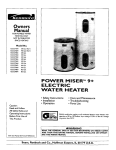
1
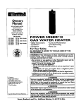
Owners
Manual
FOR POTABLEWATER
HEATING ONLY
NOT SUITABLE FOR
SPACEHEATING
NOT FOR USE IN
MOBILE HOMES
Model
153.334290
153.334390
153.334490
153.334590
No.
40
30
40
50
Gal. Short
Gal.
Gal.
Gal.
ENERGY
EFFICIENTTM5
GAS WATER
HEATER
• Care and Maintenance
• Safety Instructions
• Installation
• Operation
- Troubleshooting
• Parts List _
For Your Safety
_,N ODORANT
IS ADDED
_INAT E R HEATER
TO
THE
GAS
USED
BY THIS
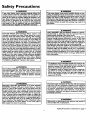
kWARNING: If the information in these instructions are not followed exactly, a fire or explosion may result, causing property
.damage, personal inlury or death.
_-Do not store or use gas.oline or other flammable vapors and liquids in the vicinity of this or any other appliance•
--WHAT TO DO IF YOU SMELL GAS
Do not try to light any appliance.
: Do not touch any electrical switch; do not use any phone in your
Caution:
Read and Follow
All Safety Rules and
Operating Instructions
Before First Use of
This Product.
building.
Immediately
call your gas supplier from a neighbor's
.phone.
i Follow the gas supplier's]nstructions.
If you can not reach your gas supplier, call the fire department.
-Installation
and service must be performed
service agency or the gas supplier.
by a qualified installer,
•
. _,WARNING
I
Improper
installation,
adjustment , alteration, service or maintenance I
can cause DEATH, SERIOUS BODILY INJURY, OR PROPERTY DAM-I
AGE. Refer to this manual for assistance or consult the local Sears
Service Center or gas utility for further information.
Flammable
vapors may be drawn by air currents
_,WARNING
of the structure to this appliance.
Save this Manual for Future Reference.
Sears, Roebuck
from
READ THE GENERAL SAFETY SECTION
BEGINNING
COVER AND THEN THIS ENTIRE MANUAL BEFORE
_,WARNING
OR OPERATING THIS WATER
HEATER.
and Co., Hoffman
Estates,
IL 60179
U.S.A.
other
areas
ON INSIDE
INSTALLING
I
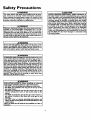
Safety Precautions
&WARNING
I
Improper installation, adjustment, alteration, service
or maintenance can cause DEATH, SERIOUS BODILY
INJURY, OR PROPERTY DAMAGE. Refer to this manual for assistance or consult your local Sears Service
Center for further nformation.
AWARNING
WATER HEATERS EQUIPPED FOR ONE TYPE GAS
ONLY: This water heater is equipped for one type gas
only. Check the model rating plate near the gas control
valve for the correct gas. DO NOT USE THIS WATER
HEATER WITH ANY GAS OTHER THAN THE ONE
SHOWN ON THE MODEL RATING PLATE. Failure to
usethe correct gascan causeproblemswhich can result in
DEATH, SERIOUS BODILY INJURY, OR PROPERTY
DAMAGE. If you have any questions or doubts consult
your gassupplier or localutility.
AWARNING
INSTALLATIONS IN AREAS WHERE FLAMMABLE LIQUIDS (VAPORS) ARE LIKELY TO BE PRESENT OR
STORED (GARAGES, STORAGE, AND UTILITY AREAS
ETC): Flammable liquids (such as gasoline, solvents
propane (LP) or butane, etc.), all of which emit fiammablG
vapors, may be improperly stored or used in such areas.
The gaswater heater pilot light or main burner can ignite
such vapors. The resulting flashback and fire can cause
death or serious burns to anyone in the area, as well as
property damage.
If installation in such areas is your only option, then the
installation must be accomplishedin a way that the pilot
flame and main burner flame are elevated from the floor
at least 18 inches. While this may reduce the chancesof
flammable vapors from a floor spill being ignited, gasoline
and other flammable substancesshouldnever be stored or
used in the same room or area containing a gas water
heater or other open flame or spark producingappliance.
NOTE: Flammable vapors may be drawn by air currents
from other areas of the structure to the appliance.
AWARNING
If this water heater will be used in beauty shops, barber
shops, cleaning establishments, or self-service laundries
with dry cleaning equipment, it is imperative that the
water heater or water heaters be installed so that combustion and ventilation air be taken from outside these
areas. Refer to the "Facts to Consider About the
Location" section of this manual and also the latest edition of the National Fuel Gas Code, ANSI Z223.1, also
referred to as NFPA 54 for specificsprovided concerning
air required.
_,WARNING
I
A fire can start if combustible materials such as clothing,I
cleaningmaterials, or flammable liquids are placed against
or next to the water heater.
AWARNING
At the time of manufacture this water heater was provided with a combination temperature-pressures relief valve
certified by a nationally recognized testing laboratory
that maintains periodic inspection of production of listed
equipment or materials, as meeting the requirements for
Relief Valves and Automatic Gas Shutoff Devices for Hot
Water Supply Systems, and the latest edition of ANSI
Z21.22 and the code requirements of ASME. If replaced,
the valve must meet the requirements of local codes,but
not less than a combination temperature and pressure
relief valve certified as meeting the requirements for
Relief Valves and Automatic Gas Shutoff Devices for Hot
Water Supply Systems,ANSI Z21.22 by a nationally recognized testing laboratory that maintains periodic
inspection of production of listed equipment or
materials.
The valve must be marked with a maximum set pressur_
not to exceed the marked hydrostatic working pressure"
of the water heater (150 Ibs./sq. in.) and a discharge
capacity not less than the water heater input rate as
shown on the model rating plate. (Electric heaters watts divided by 1000 x 3415 equal BTU/Hr. rate.)
Your local jurisdictional authority, while mandating the
use of a temperature-pressure relief valve complying
with ANSI Z21.22 and ASME, may require a valve model
different from the one furnished with the water heater.
Compliance with.such Ioca_ requirements must be satisfied by the installer or end user of the water heater with
a locally prescribed-temperature-pressure relief valve
installed in the designatedopemng m the water heater in
place of the fa-c_ Fu-i_fsll-edvalve.
For safe operation of the water heater, the relief valve
must not be removed fr_mm
TtJs-_lesignated opening or
plugged.
_ ................
_
........
The temperature-pressure relief valve must be installed
directly into _he-flttlng of the water 4seaterdesignated for
the relief valv_ Positionthe valve downward and provide
tubing so that any_lsc-_r-_'wrn_i_
only_vithin 6 inches
above, or at any distance below the structural floor. Be
certain that no contact is made with any live electrical
part. The discharge opening must not be blocked or
reduced in size under any circumstances. Excessive
length, over 30 feet, or use of more than four elbows can
cause restriction and reduce the discharge capacity of
the valve.
No valve or other obstruction is to be placed between
the relief valve and the tank. Do not connect tubing
directly to dischargedrain unlessa 6" air gap is provided.
To prevent bodily injury, hazard to life, or property damage, the relief valve must be allowed to dischargewater
in quantities should circumstances demand. If the discharge pipe is not connected to a drain or other suitable
means, the water flow may causeproperty damage.
The Discharge Pipe:
Must not be smaller in size than the outlet pipe size of
the valve, or have any reducing couplings or other
restrictions.
• Must not be pluggedor blocked.
• Must be of material listed for hot water distribution.
• Must be installed so as to allow complete drainage of
both the temperature-pressure relief valve, and the discharge pipe.
• Must terminate at an adequate drain.
• Must not have any valve between the relief valve and
tank.
Safety Precautions
AWARNING
AWARNING
A gas water heater cannot operate properly without the
correct amount of air for combustion. Do not install in a
confined area such a closet, unless you provide air as
shown in the "Facts to Consider About the Location" section. Never obstruct the flow of ventilation air. If you have
any doubts or questions at all, call your gas company.
Failure to provide the proper amount of combustion air
can result in a fire or explosion and can cause DEATH
SERIOUS BODILY INJURY,OR PROPERTY DAMAGE.
This water heater must not be installed directly on carpeting. Cavpe_ng must be protected by a metal or wood
panel beneath the appliance extending beyond the full
width and depth of the appliance by at least 3 inches
(76.2mm) in any direction, or if the applia6ce is installed
in an alcove or closet, the entire floor must be covered h
the panel. Failure to heed this warning may result in
fire hazard.
AWARNING
&WARNING
VENT DAMPERS - Any vent damper, whether it is operated thermally or otherwise must be removed if its use
inhibits proper draftingof the water heater. •
Thermally Operated Vent Dampers: Gas-fired water
heaters having thermal efficiency in excess of 80% may
produce a relatively low flue gastemperature. Such tamperatures may not be high enough to properly open thermaily operated vent dampers. This would causespillageof
flue gasesand may causecarbon monoxidepoisoning.
Vent dampers must boar evidenceof certification as complying with the latest edition of American National
Standard ANSI Z21.68 (ANSI Z21.66 & 67, respectively,
cover electrically and mechanically actuated vent
dampers). Before installation of any vent damper, consult
your local Se._ Service Center or the gas utility for further informat|on.
HOTTER WATER CAN SCALD: Water heaters are
intended to produce hot water. Water heated to a tamperature which will satisfy clothes washing,dish washing,
and other sanitizing needs can scald and permanently
injure you upon contact. Some people are more likely to
be permanently injured by hot water than others. These
includethe elderly, children, the infirm, or physically/mentally handicapped.If anyone usinghot water in your home
fits into one of these groups or if there is a local code or
state law requiring a certain temperature water at the hot
water tap, then you must take specialprecautions.In addition to usingthe lowest possibletemperature setting that
satisfiesyour hot water needs, a means such as a mixing
valve, shouldbe used at the hot water taps used by these
people or at the water heater. Mixing valvesare available
at plumbing supply or hardware stores. Follow manufacturers instructions for installation of the valves. Before
changingthe factory setting on the thermostat, read the
"Temperature Regulation" section in this manual.
J, WARNING
• The appliance and its individualshutoffvalve must be disconnected from the gas supplypiping system during any
pressure testing of the gas system at test pressures in
excessof ½ pound per squareinch(3.5kPa).
• The appliance must be isolated from the gassupply piping system by closing its individual manual shutoff valve
during any pressuretesting of the gassupply piping system at test pressures equal or less than Yzpound per
squareinch (3.5kPa).
AWARNING
Soot build-up indicates a problem that requires correction before further use. Turn "OFF" gas to water heater
and leave "OFF" until repairs are made, because failure
to correct the cause of the sooting can result in a fire or
explosion causing DEATH, SERIOUS BODILY INJURY,
OR PROPERTY DAMAGE.
_,WARNING
A, WARNING
Chemical vapor corrosion of the flue and vent system
may occur if air for combustion containscertain chemical
vapors. Spray can propellants,cleaningsolvents,refrigerator and air conditioner refrigerants, swimming pool
chemicals, calcium and sodium chloride, waxes, bleach,
and processchemicals are typical compounds which are
potentially corrosive.
BEFORE LIGHTING [PROPANE (L.P.) GAS WATER
HEATERS]: Propane (L.P.) gas is heavier than air. Should
there be a leak in the system, the gaswill settle near the
ground. Basements, crawl spaces, skirted areas under
mobile homes (even when ventilated), closets and areas
below ground level will serve as pocketsfor the accumulation of this gas. Before attempting to light or relight the
water heater'spilot or turning on a nearby electrical light
switch, be absolutely sure there is no accumulated gas in
the aro_ Search for odor of gasby sniffingat ground level
in the vicinity of the appliance. If odor is detected, follow
steps indicated at "For Your Safety" on the cover page of
this manual then leave the premises.
_,WARNING
Obstructed or deteriorated vent systems may present a
serioushealth risk or asphyx at on.
Safety Precautions continued on page 4
3
Safety Precautions
&CAUTION
&WARNING
WATER HEATERS EVENTUALLY LEAK: Installation of
the water heater must be accomplished in such a manner
that if the tank or any connections shouldleak, the flow of
water will not cause damage to the structure. When such
locations cannot be avoided, a suitable drain pan should
be installed under the water heater, Drain pans are avail- i
able at your local Sears store. Such a drain pan must be
not greater than I _ inchesdeep, have a minimum length
and width of at least 2 inches greater than the water
heater dimensions and must be piped to an adequate
drain. The pan must not restrict combustion air flow.
Under no circumstances is the manufacturer or Sears to
be held liable for any water damage in connection with
this water heater,
The water heater with draft hood installed must be preperly vented to a chimney which terminates outdoors.
Never operate the water heater unless_t _svented to the
outdoors and has adequate air supply to avoid risks of
mproper operat on, expos on or asphyxation.
&WARNING
Minimum clearancesbetween the water heater and combustible or non-combustible construction are I" at the
sidesand rear, 4" at the front, and 6" from the vent pipe.
Clearance from the top of the jacket is 18" on most models. Note that a lesserdimension may be al owed on some
models. Refer to the label on the water heater adjacent to
the gascontrol valvefor all clearances.
I
&WARNING
l
Do not use this appli_of
It has been under _
water. Immediately call a Sears Service Technician to I
inspectthe applianceand to replace the gascontrol or any /
part of the burner systemwhich hasbeen under water.
&WARNING
HYDROGEN GAS: Hydrogen gascan be producedin a hot
water system that has not been used for a long period of
time (generally two weeks or more). Hydrogen gas is
extremely flammable and explosive.To prevent the possibility of injury under these conditions, we recommend the
hot water faucet be opened for several minutes at the
kitchen sink before any electrical appliances which a.re
connected to the hot water system am used (suchas a dlshwesher or washing machine). If hydrogen gas is present,
there will probably be an unusual sound similar to air
escaping through the pipe as the hot water faucet is
opened. There must be no smoking or open flame near
the faucet at the time it isopen.
&WARNING
INSULATING JACKETS: When installing an external
water heater InsulationJacketon a gaswater heater:
• DO NOT cover the temperature-pressure relief valve.
• DO NOT put Insulation over any part of the top of the
gaswater heater.
• DO NOT put insulation over the gascontrol valve or gas
control valve/burner cover, or any access areas to the
burner.
• DO NOT let insulation around the gas water heater to
get within 8 inches of the floor (air must get to the
burner).
• DO NOT cover or remove operating instructions, and
safety related warning labelsand materials affixed to the
water heater.
Failure to heed this will result in the possibilityof a Ere or
explosion.
Table of Contents
Safety Precautions ...................................................................................................
2_
Table of Contents ...................................................................................................
5
Customer Responsibilities ................................................................................
6
Product bpecincations ...............
6
:.................................................................................
Materials and Basic Tools Needed ............................................................................................... 7
Materials Needed ......................................................................................................................................................................
Basic Tools ................................................................................................................................................................................
7
7
Installation Instructions ...................................................................................
8.!6
Removing the Old Water Heater ...............................................................................................................................................
Facts to Consider About the Location .......................................................................................................................................
8
9
Combustion Air and Ventilation for Appliances in Unconfined Spaces ...................................................................................
10
Combustion Air and Ventilation for Appliances in Confined Spaces .......................................................................................
10
Water Piping ...........................................................................................................................................................................
11
Temperature-Pressure
Relief Valve ...........................................................................................................................................
12
Filling the Water Heater ..........................................................................................................................................................
13
Venting .....................................................................................................................................................................
2........ 13-14
Gas Piping .........................................................................................................................................................................
14-15
Installation Checklist ..............................................................................................................................................................
16
'-'-uoeratm_
: Instructions .........................................................................................
17-19
l:ighting ............-. ................................................................................................................................................................
Temperature Regulation ..........................................................................................................................................................
17-18
19
Service and Ad iustment .......................................................................................
20-21
Tank (Sediment) Cleaning ......................................................................................................................................................
Venting System Inspection ......................................................................................................................................................
Burner Inspection ...................................................................................................................................................................
Burner Cleaning .....................................................................................................................................................................
Draining .................................................................................................................................................................................
Temperature-Pressure
Relief Valve Operation ..........................................................................................................................
Drain Valve Washer Replacement ...........................................................................................................................................
Homekeeping
.........................................................................................................................................................................
Service ....................................................................................................................................................................................
20
20
20
20
21
21
21
21
21
Troubleshooting Guide ...................................................................................
22-25
22 23
Start Up Conditions ..........................................................................................................................................................
Condensation
.......................................................................................................................................................................
Smoke/Odor .........................................................................................................................................................................
Thermal Expansion .........................................................................................................................................................
Strange Sounds .....................................................................................................................................................................
Operational Conditions .....................................................................................................................................................
-
22
22
22 - 23
23
23-24
Smelly Water .........................................................................................................................................................................
Air in Hot Water Faucets ......................................................................................................................................................
23
23
High Temperature Shut Off System ......................................................................................................................................
Not Enough Hot Water ........................................................................................................................................................
Water is Too Hot ..................................................................................................................................................................
24
24
24
Leakage Checkpoints
..............................................................................................................................................................
25
Parts Order List .....................................................................................................
26-27
5
Customer
RespOnsibilities
Thank You for
This manual contains instructions for the installation, operation, and maintenance of the gas-fired water heater. It also
contains warnings through out the manual that you must read
and be aware of. All warnings and all instructions are essential
to the proper operation of the water heater and your safety.
Since we cannot put everything on the first few pages, READ
THE ENTIRE MANUAL BEFORE ATTEMPTING TO
INSTALL OR OPERATE THE WATER HEATER.
• The installation must conform with the instructions in this
manual; gas company rules; and Local Codes, or in the
absence of Local Codes, with the latest edition of the National
Fuel Gas code, ANSI Z223.1, also referred to as NFPA 54.
This publication is available from your local government or
public library or gas company or by writing NFPA,
Batterymarch Park,Quincy, MA 02269.
• Ifaker reading this manualyou have any questions or do not
understand any portion of the instructions, call the Sears
Service Center.
- Carefully plan the place where you are going to put the water
heater. Correct combustion, vent action, and vent pipe installation are very important in preventing death from possible
carbon monoxide poisoning and fires.
Examine the location to ensure the water heater complies with
the "Facts to Consider About the Location" section in this
manual.
• For California installation this water heater must be braced,
anchored, or strapped to avoid falling or moving during an
earthquake. See instructions for correct installation procedures. Instructions may be obtained from your local dealer,
wholesaler, public utilities or California Office of the State
Architect, 400 P Street, Sacramento, CA 95814.
purchasinga
Sears water heater.
Properly installed and maintained, it should give you years of
trouble free service. If you should decide that you want the new
water heater professionally installed by Sears call the local Sears
Service Center or any Sears store. They will arrange for prompt,
quality installation by Sears authorized contractors.
Abbreviations Found In This Instruction Manual
A.G.A. - American Gas Association
A.N.S.I. - American National Standards Institute
A WARNING
This gas-fired water heater is design certified by the
American Gas Association Laboratories under American
National Standards for Gas Water Heaters. The installation must conform with this manual, Local Codesand with
the latest edition of the National Fuel Gas Code, ANSI
Z223.1.
This publicationis availa.'ble
from your local governmentor
public library, gas company, or by writing NI;PA,
Batterymarch Park, Quincy, MA 02269.
• Read the "Safety Precautions" section, pages 2 through 4 of
this manual first and then the entire manual carefully. If you
don't follow the safety rules, the water heater will not operate
properly.
It could cause DEATH,
SERIOUS
BODILY
INJURY ANDIOR
PROPERTY DAMAGE.
Product Specifications
MODEL
NUMBER
TANK
CAPACITY
IN GALLONS
TYPE
OF
GAS
DIMENSIONS IN INCHES
B.T.U.
RATE
RECOVERYRATE
GALS.PER HOUR
@ 90°F RISE
MINIMUM
DIAMETER
HEIGHTTO
JACKEI'TOP
VENT
PIPE
153.334290
40
NATURAL
35,000
35.8
20
47_
153.334390
30
NATURAL
28,000
28.7
3"
16
56
153.334490
40
NATURAL
30,000
31.0
3"
18
56_
153.334590
50
NATURAL
30,000
31.0
3"
20
56_
3"-4"
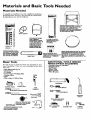
Materials and Basic Tools Needed
Materials
Needed
To simplify the installation Sears has available the installation
parts shown below. You may or may not need all of these materials, depending on your type of installation.
WATER HEATER STAND 24"x24"xl 8"
FOR USE WITH WATER HEATERS
INSTALLED IN RESIDENTIAL
GARAGES HAVING A DIAMETER 24"
OR LESS AND A RATED CAPACITY
75 GALLONS OR LESS
@
VENT
ELBOW
EXPANSION
TANKS
FOR THERMAL
EXPANSION
CONDITIONS AVAILABLE IN
2 GALLON AND 5
GALLON CAPACITY
THROUGH
LOCAL
SEARS STORE OR
SERVICE CENTERS
WATER HEATER INSTALLATION KIT WITH FLEXIBLE CONNECTORS
FOR
3/4" OR I/2" THREADED
OR COPPER PLUMBING
(
VENT
PIPE
FLEXIBLE WATER
HEATER GAS CONNECTOR WITH
FITTINGS
WATER HEATER HEAT
TRAPS HELP REDUCE HEAT
LOSS DUE TO THERMAL
SYPHONING
Basic Tools
ADDITIONAL
TOOLS
NEEDED
WHEN
SWEAT SOLDERING
You may or may not need all of these tools, depending on your
type of installation. These tools can be purchased at your local
Sears store.
•
•
•
•
•
•
•
DRAIN PANS AVAILABLE IN 20" DIAMETER FOR WATER HEATERS HAVING A
DIAMETER I 8" OR LESS AND AVAILABLE IN 28" DIAMETER FOR WATER
HEATERS HAVING A DIAMETER 26" OR
LESS
•
•
•
•
•
•
Pipe Wrenches (2) 14"
Screwdriver
Tin Snips
6 Foot Tape of Folding Rule
Garden Hose
Drill
Pipe dope or Teflon Tape
Tubing Cutters or Hacksaw
Propane Torch
Soft Solder
Solder Flux
EmeryCIoth
Wire Brushes
HACKSAW
GARDEN
HOSE
6 FOOT TAPE
3/4" WIRE BRUSH
PIPE
WRENCH
SLOT-HEAD
SCREWDRIVER
112"WIRE BRUSH
PHILLIPS
SCREWDRIVER
PROPANE
TORCH
TIN SNIPS
ROLL OF LEAD FREE
SOFT SOLDER
ROLL OF TEFLON TAPE
(USE ONLY ON WATER
CONNECTIONS)
PIPE DOPE (SQUEEZE TUBE)
(USE FOR WATER AND
GAS CONNECTIONS)
DRILL
ROLL OF EMERY
CLOTH
7
SOLDER FLUX
TUBING
CUTTER
Installation
Instructions
Removing the Old Water
OTurn
"OFF"
Heater
ODisconnect
the vent pipe from the draft hood where
they connect to the water heater. In most installations
the vent pipe can be lifted off after any screw or other
attached devices are removed. Dispose of the draft
hood. The new water heater has the draft hood which
must be used for proper operation.
the gas supply to the water heater.
_,WARNING
"
[
If the main gas line shutoff serving all g._. appliances is I
used, also shut "OFF" the gas at each appliance. Leave all [
gas appliances shut "OFF" until the water heater Installa-
®
tion is €omp ete.
®
®
a.
If you have copper piping to the water
heater, the two copper water pipes can be
cut with a hacksaw approximately 4"
away from where they connect to the
water heater. This will avoid cutting off
the pipes too short. Additional cuts can
be made later if necessary. Disconnect
the tempereture-pressure
relief valve
drain line. When the water heater is
drained, disconnect the hose from the
drain valve. Close the drain valve. The
water heater is now completely disconnected and ready to be removed.
Turn "OFF"
the water to the water
heater. Some installations
require that
the water be turned off to the entire
house,
®
QCh,,eck
again to make sure the gas supply
is OFF
to the water heater. Then disconnect the gas supply connection from
the gas control valve.
Attach a hose to the ware[
heater drain
valve and put the other end in a floor
drain or outdoors. Open the water heater
drain valve. Open a nearby hot water
faucet which will relieve pressure in the
water heater and speed draining.
AWARNING
The water passing out of the drain valve may be extremely
hot. To avoid being scalded, make sure all connections are
tight and that the water flow is directed away from any
person.
Q
b. If you have galvanized pipe to the water
heater, loosen the two galvanized pipes
with a pipe wrench at the union in each
line. Also disconnect the piping remaining to the water heater. These pieces
should be saved since they may be needed when reconnecting
the new water
heater. Disconnect the temperature-pressure relief valve drain line. When the
water heater is drained, disconnect the
hose from the drain valve. Close the
drain valve. The water heater is now
completely disconnected and ready to be
removed.
ACAUTION
Mineral buildup or sediment may have accumulated in the I
I old water heater. This causes the water heater to be much
heavier than normal and this residue, if spilled out, could
I cause staining.
I
Installation
Instructions
Facts to Consider
Location
About the
You should carefully choose an indoor location for the new
water heater, because the placement is a very important consideration for the safety of the occupants in the building and for
the most economical use of the appliance. This water heater is
not for use in mobile homes or outdoor installation.
Whether replacing an old water heater or putting the water
heater in a new location, the following critical points must be
observed.
• The location selected should be indoors as close as'practical
to the gas vent or chimney to which the water heater vent is
going to be connected, and as centralized with the _ater piping system as possible. The water heater, as all water heaters,
will eventually leak. Do not install without adequate
drainage provisions where water flow will cause damage.
A CAUTION
WATER HEATERS EVENTUALLY LEAK: Installationof the
water heater must be accomplishedin sucha manner that if
the tank or any connectionsshouldleak,the flowof water will
not causedamageto the structure.When suchlocationscannot be avoided,a suitable drain pan shouldbe installedunder
the water heater.Drain pansare availableat your localSears
store. Such a drain pan must be not greater than 1½ inches
deep, havea minimum length and width of at least 2 inches
greater than the water heater dimensionsand must be piped
to anedeqeatedrain.The pan mustnot restrict combustionair
flow.Under no circumstances
is the manufactureror Searsto
be held liable for any water damage in connectionwith this
water heater.
(cont'd)
• The location selection must provide adequate clearances for servicing and proper operation of the waterheater.
AWARNING
This water heater mustnot be installeddirectlyon carpeting.
Carpeting must be protected by a metal or wood panel
beneath the appliance extendingbeyondthe full width and
depth of the applianceby at least 3 inches(76.2mm) in any
direction,or if the appliance isinstalledin an alcove or closet,
the entiretloor mustbe coveredby the panel.Failureto heed
this wam.ingmayresultin a Erehazard.
AWARNING
Minimum clearancesbetween the water heater and combustibleor non-combustibleconstructionare I" at the sides
and rear,4" at the front, and 6" from the vent pipe.Clearance
from the top of the jacketis 18"on mostmodelg Note that a
lesserdimensionmaybe allowedon somemodelL Referto the
labelon the water heater adjacentto the gascontrolvalvefor
all clearance_
12" MAX
VENTILATION
AlE
OPENINGS
TOP VIEW
OF CLOSET
WITHOUT DOOR
__
12 wMAX.
AWARNING
INSTALLATIONSIN AREASWHERE FLAMMABLELIQUIDS
(VAPORS) ARE LIKELY TO BE PRESENT OR STORED
GARAGES, STORAGE, AND UTILITY AREAS,"ETC):
Flammableliquids(suchasgasoline,solvents,propane(LP) or
butane, etc.), all of which emit flammable vapors, may be
improperlystored or usedin suchareas.The gaswater heater
pilot light or main burnercanignitesuchvapors.The resulting
flashback
and fire can causedeathor seriousburnsto anyonein
the area,aswellaspropertydamage.
If installationin suchareasisyour onlyoption,then the installation must be accomplishedin a way that the pilot flame and
main burnerflameareelevatedfrom the floor at least18inches.
While this may reducethe chancesof flammablevaporsfrom a
floorspillbeingignited,gasoline
and otherflammablesubstances
shouldneverbe stored or usedin the same room or area containinga gaswater heateror otheropenflameor sparkproducingappliance.
NOTE: Flammablevaporsmay be drawnby air currentsfrom
otherareasofthe structureto the appliance.
AWARNING
Propellants of aerosolspraysand volatile compounds,(cleaners, chlorinebasedchemicals,refrigerants,etc.) in additionto
beinghighlyflammablein manycases,will alsochangeto corrosive hydrochloricacid when exposed to the combustion
productsof the water heater.The results can be hazardous,
and alsocauseproductfailure.
11
TOP VIEW ]" MIN.
OF CLOS)SEIT
WITH DOOR
AIR DUCT
Figure I ]
AWARNING
A gaswater heater cannotoperateproperlywithout the correct amount of air for combustion.Do not install in a confined
areasucha closet,unlessyou provideair asshownin the "Facts
to ConsiderAbout the Location"section.Never obstructthe
Ilowofventilationair. If you haveany doubtsor questionsat all,
callyour gascompany.Failureto providethe properamount of
combustionair canresult in a fire or explosionand cancause
DEATH,SERIOUSBODILYINJUR_,OR PROPERTYDAMAGE.
A, WARNING
If this water heater will be usedin beautyshops,barbershops,
cleaningestablishments,or self-servicelaundries with dry
cleaningequipment,it isimperativethat the water heater or
water heatersbe installedso that combustionand ventilation
air be takenfrom outsidethese areas.Refer to the "Facts to
ConsiderAbout the Location"section of this manual and also
the latestedition ofthe NationalFuelGasCode, ANSI Z223.1,
alsoreferred to as NFPA 54 for specificsprovided concerning
air required.
Installation
Instructions
(cont'd)
Combustion Air and Ventilation
for Appliances Located in
Unconfined Spaces
Uncomemed Space is a space whose volume is not less than 50
cubic feet per 1,000 Btu per hour of the aggregate input rating
of all appliances installed in that space. Rooms communicating
directly with the space in which the appliances are installed,
through openings not furnished with doors, are considered a
part of the unconfined space.
In unconfined spaces in buildings, infiltration may be adequate
to provide air for combustion, ventilation and dilution of flue
gases. However, in buildings of tight construction (for example,
weather stripping, heavily insulated, caulked, vapor barrier, etc.),
additional air may need to be provided using the methods
described in Combustion Air and Ventilation for Appliances
Locate.din Confined Spaces, b.
1. When directly communicating with the outdoors each openin._ shall have a minimum free area of 1 square inch per 4,000
BI w per hour of total input rating of all equipment in the
enclosure. (See Figure 3.)
2. When communicating with the outdoors through vertical
ducts, each opening shall have a minimum free area of 1
square inch per 4,000 BTU per hour of total input rating of
all equipment in the enclosure. (See Figure 4.)
Combustion Air and Ventilation
for Appliances Located in
Confined Spaces
Confined Space is a space whose volume is less than 50 cubic
feet per 1,000 Bru per hour of the aggregate input rating of all
appliances installed in that space.
a. ALL AIR FROM INSIDE BUILDINGS:
(See Page 9 Figure 1, and Figure 2 below)
The confined space shall be provided with two permanent
openings communicating directly with an additional room(s)
of sufficient volume so that the combined volume of all
spaces meets the criteria for an unconfined space. The total
input of all sas utilization equipment installed in the combined space shall be considered in making this determination.
Each opening shall have a minimum free area of one square
inch per 1,000 BTU per hour of the total input rating of all
gas utilization equipment in the confined space, but not less
than I00 square inches. One opening shall commence within
12 ....m me top ano" one commencing
" within 12" of the bottom of the enclosure.
I Figure
Figure 4 }
3. When communicating with the outdoors through horizontal
ducts, each opening shall have a minimum flee area of 1
square inch per 2,000 BTU per hour of toral input rating of
all equipment in the enclosure. (See Figure 5.)
4. When ducts are
area as the free
The minimum
shall not be less
2]
b. ALL AIR FROM OUTDOORS: (see Figures 3-5)
The confined space shall be provided ,with two permanent
openings, one commencing within 12 of the top and one
commencing within 12" from the bottom of the enclosure.
The openings shall communicate directly, or by ducts, with
the outdoors or spaces (crawl or attic) that freely communicate Withthe outdoors.
Figure
5,
used, they shall be of the same cross-sectional
area of the openings to which they connect.
short side dimension of rectangular air ducts
than 3". (See Figure 5.)
Louvers and Grilles: In calculating free area, consideration
shall be given to the blocking effect of louvers, grilles or
screens protecting openings. Screens used shall not be smaller
than ¼-mesh. Iftbe free area through a design of louver or
grille is known, it should be used in calculating the size opening required to provide the free area specified. If the design
and free area is not known, it may be assumed that wood louvers will be 20-25 percent free area and metal louvers and
grilles will have 60-75 percent free area. Louvers and grilles
shall be fixed in the open position or interlocked with the
equipment
so that they are opened automatically
during
equipment operation.
6. Special Conditions
Created by Mechanical
Exhausting
or
Fireplaces: Operation
of exhaust fans, ventilation systems,
clothes dryers or fireplaces may create conditions requirin[_
special attention to avoid unsatisfactory operation of installecl
gas utilization equipment.
q
10
Installation
Water
Instructions
Piping
AWARNING
Look at the top cover of the water heater. The cold water
inlet is markedcold. Put two or three turns of teflon tape
around the threaded end of the threaded_to-sweat coupling
and around both ends of the 3A threaded nipple. Using flexible connectors, connect the cold water pipe to the coldwater
inlet of the water heater.
HOTTER WATER CAN SCAI._. Water heaters are intended to
produce hot water. Water _
to a temperature which will
satisfyclothes washing, dishwathm_ and other sanitizing needs
can scaldand permanently injure you upon contact. Some people are more likely to be permanently injured by hot water than
other*. These includethe elderly, child_n, the infirm, or physically/mentaily handicapped.If anyone usinghot water in your home
fits into one of these groups or if there is a localcede or state law
requiring a certain temperature water at the hot water _ then
you must take speciaiprecautions In addition to usingthe lowest
possil_etemperature setting that satisfiesyour hot water needs,
a means suchas a mixing valve, shouldbe usedat the hot water
taps used by these people or at she water heater. Mixing valves
are availableat plumbing supplyor hardware store_ Followmanufacturers instructions for installation of the valves. Before
changing the factory setting on the thermostat, read the
"Temperature Regulation" section in this manual.
AE,WARNING
This water heate_connected
heating systems or component(s)
potable water heating appliance.
]
used with
_,WARNING
Toxic chemicals suc_reatment
or non-potable
water heating
be introduced
(cont'd)
into a potable
water
INSTALLATION
COMPLETED
SEARS INSTALLATION
CONNECTORS
FLEXIBLE WATER
H_T
to any
a non-[
.
appliances
NOTE: This water heater is super insulated to minimize
heat loss from the tank. Further reduction in heat loss
can be accomplished
by insulating
the hot water lines
from the water heater.
Ig3
OUTLET
COLD INLET
WATER LINE
TO HOUSE
]
THREADED
TO
SWEAT COUPLING
THREADED TO
SWEAT COUPLING
]
of boders [
shall never [
heating system.
USING
KIT
SHUTOFF
NIPPLE
NIPPLE
J
If a water heater is installed in a closed water supply system;
such as one having a back-flow preventer, check valve, water
meter with a check valve, etc.., in the cold water supply; means
shall be provided to control thermal expansion.
Contact the
local utility or local Sears Service Center on how to control this
situation.
PRESSURE
RELIEF VALVE
NOTE: To ,protect against untimely corrosion of hot and
cold water lattings, it is strongly recommended
that all-electric unions or couplings
be installed on this water heater
when connected to copper pipe.
[]
PIPE (Do not cap
or plug)
The illustration shows the attachment of the water piping to the
water heater. The water heater is equipped
with 3A" water
connections.
NOTE: If using copper tubing, solder tubing to an adapter
before attaching the adapter to the cold water inlet connection. Do not solder the cold water supply line directly to the
cold water inlet. It will harm the dip tube and damage the
tank.
•
_" AIR GAP
Look at the top cover of the water heater. The water outlet is
marked hot. Put two or three turns of teflon tape around the
threaded end of the threaded-to-sweat
coupling and around
both ends of the ¾" threaded nipple. Using flexible connectors, connect the hot water pipe to the hot water outlet on
the water heater.
FLOOR
11
DRAIN
Installation
Instructions (cont'd)
Temperature-Pressure Relief Valve
_,WARNING
_WARNING
The temperature-pressure relief valve must be manually
operated at least once a yea_ Caution should be taken to
ensurethat (I) no one is in front of or aroundthe outlet of
the temperature-pressuren.-qief
valve dischargeline, and (2)
the water manually dischargedwill not cause any bodily
injury or property damage because the water may be
exeremalyhot
At the time of manufacturethis water heater was provided
with a combinationtemperature-pressuresrelief valvecertified
by a nationally recognized testing laboratory that maintains
periodicinspectionof productionof listedequipmentor materials, as meeting the requirements for Relief Valves and
AutomaticGas ShutoffDevicesfor Hot Water SupplySystems,
and the latest editionof ANSI Z21.22 and the code requirementsof ASME. If replaced, the valvemust meet the requirementsof localcedes,but not lessthan a combinationtempera.
ture and pressurerelief valvecertified asmeeting the requiremerits for ReliefValvesandAutomatic GasShutoffDevicesfor
Hot Water SupplySystems,ANSI Z21.22bya nationally recognizedtesting laboratorythat maintainsperiodicinspectionof
productionof listedequipmentor materials.
The valvemust be niarked with a maximumset pressurenot
to exceed the marked hydrostaticworking pressureof the
water heater (150 IbsJsq.in.) and a dischargecapacitynot less
than the water heaterinput rate as shownon the modelrating
,late. (Electric heaters - watts dividedby 1000x 34!5 equal
BTU/Hr.rate.)
Yourlocaljurisdictionalauthority,whilemandatingthe useof a
temperature-pressure
reliefvalvecomplyingwith ANSI 7-21.22
and ASME, may require a valvemodel differentfrom the one
furnishedwith the water heater.
Compliancewith suchlocalrequirements mustbe satisfiedby
the installeror end user ofthe water heater with a locallyprescribedtemperature-pressure
relief valveinstalledin the designated openingin the water heater in placeof the factoryfor_
nishedvalve.
Forsafeoperationofthe water heater,the relief valvemustnot
be removed from it'sdesignated
openingor plugged.
The temperature-pressure
relief valvemustbe installeddirectly
intothe fittingof thewater heaterdesignated
for the reliefvab/e.
: Positionthe valvedownwardand providetubingsothat anydischargewill exit onlywithin 6 inchesabove,or at any distance
belowthe structuralfloor.Be certainthat no contactis made
with anylive electricalpart. The discharge
openingmust not be
blockedor reduced in sizeunder any circumstances.
Excessive
length,over 30 feet,or useof more than fourelbowscancause
restriction andreducethe discharge
capacityofthevalve.
No valveor other obstructionisto be placedbetweenthe relief
valveandthe tank. Do not connecttubingdirectlyto discharge
drainunlessa 6" air gapisprovided.
To preventbodilyinjury,hazard to life, or propertydamage,the relief valvemustbe alk)wed
to discharge
water in quantitiesshouldcircumstances
demand.If
the discharge
pipeis not connectedto a drainor other suitable
means,thewater flowmaycausepmperty damage.
The DischargePipe:
Must not be smallerin size than the outlet pipesize of the
valve,or haveanyreducing couplings
or otherrestrictions.
Mustnot be pluggedor blocked.
Mustbe ofmateriallistedfor hot water distribution.
Must be installedso as to allow completedrainageof both
the temperature-pressure relief valve, and the discharge
If after manually operating the valve, it fails to completely
reset and continuesto release water, immediatelydose the
cold water inlet to the water heater, follow the draining
instructions, and replace the temperature-pressure relief
valvewith a newone.
SHUTOFF
VALVE
\
[]
COLD
PRESSURE
RELIEF VALVE
(Do not rap or plug)
6" AIR GAP
FLOOR
DRAIN
RELIEFVALVEOPENING
At the time of manufacture,
this waterheaterwasprovided
with a combination
temperature-pressure
reliefvalvelistedascomplyin
I withthe standard
forrelief vahesand
automedcgassh.t-offdevices
for hot water supplysystems,ANS_Z2i.22. For safe
operationof the waterheater,the reliefvalvemustnot be removedfromiu designated
pointofinstallation
o_plugged.
Yourk_caliurlsdi_onal au_hori_,whilemandetfo_
the use of a tempera_ure-pr_sure
reliefval_ecomplying
with ANSI7.21.22andASHE.rn_ requirea valvemode_different
fromtht onefurnished
withthewaterbea_e_
Compliance
withsuchlocalrequirernenumustbesatisfied
bythe installer
or enduser
ofthe waterheaterwitha focallyprescribed
temperature-pressure
reliefvalveinstalled
in the designated
openiog
in the waterhe_te_
Seemanualheading
- Temperature-Pressure
ReliefValves"
for installationandmaintenanceof reliefvalve,discharge
line,andothersafetyprecautions.
p_pe.
Mustterminate at an adequatedrain.
Must not haveanyvalvebetweenthe retiefvalveand tank.
12
Installation
Filling the Water
Instructions
(cont'd)
Heater
I
ACAUT,ON
For proper venting in certain installations, a larger diameter vent
pipe may be necessary. Due to great variances in installations,
unforeseeable by the manufacturer of the water heater, you must
consult your gas company to aid you in determining tile proper
venting for your water heater from the vent tables in the latest
edition of the National Fuel Gas Code ANSI Z223.1, also
referred to as NFPA 54.
Never usethis water heater unlessit is completelyfilledwith I
water. To preventdamageto the tenk, the tank must be filled [
with water. Water must flow from the hot water faucet
bofomturnmg _DN gasto the wnter heater.
To fill the water heater with water:
• Close the water heater drain valve by turning the handle to
the right (clockwise). The drain valve is on the lower front of
the water heater.
• Open the cold water supply valve to the water heater. NOTE: The cold water supply valve must be left open
when the water heater is in use.
• To insure complete filling of the tank, allow air to exit by
opening the nearest hot water faucet. Allow water t? run
until a constant flow is obtained. This will let air out of the
water heater and the piping.
• Check all new water piping for leaks. Repair as needed.
Check the venting system for signs of obstruction or deterioration and replace ir needed.
The combustion and ventilation air flow must not be obstructed.
A WARNING
Obstructed or deterioratedventsystemsmay presenta serious
healthrisk or asphyxiation.
•
Place the draft hood legs in the receiving holes on the top of
the water heater. The legs will snap in the holes to give a tight
fit.
•
Place the vent pipe over the draft hood. With the vent pipe in
position, drill a small hole through both the vent pipe and
draft hood. Secure them together with a sheet metal screw.
Venting
AWARNING
VENT DAMPERS- Any vent damper,whether it is operated
t_rmally or otherwisemust be removedifi_ useinhibitsproper draftingofthe water heater.
Thermally Operated Vent Dampers:Gas-firedwater heaters
havingthermal efficiencyin excessof 80%may producea relatively lowflue gastemperature. Suchtemperaturesmay not be
high enough to properly open thermally operated vent
damper_This wouldcausespillageof flue gasesandmay cause
carbonmonoxidepoisoning.
Ventdampersmustbear evidenceof certificationas complying
with the latest editionof American National StandardANSI
Z21.68 (ANSI Z21.66 & 67, respectively,
coverelectricallyand
mechanically
actuatedventdampers).Beforeinstallationofany
ventdamper,consultyourlocalSearsServiceCenteror the gas
utilityfor further information.
DRAFT
HOOD
VENT ] [
_
,_-_
f
,_-_'_fSCREW_--'I DRAFT
__ VENT
DRAFT
HgOD.
_
HOOD
TO OUTDOORS
OR
CHIMNEY
AWARNING
The water heater with draft hood installedmust be properly
ventedto a chimney whichterminates outdoors.Never operate the water heaterunlessit isventedto the outdoorsand has
adequateair supplyto avoidrisksof improperoperation,explosionor asphyxiation.
AWARNING
To insure proper venting of this gas-firedwater heater, the
correctvent pipediameter mustbe utilized,Any additionsor
deletionsof other gasapplianceson a common ventwith this
water heater may adverselyaffectthe operal_n of the water
heater.Consultthe localSearsService Center or gasutility if
anysuchchangesare planned,
AWARNING
The vent pipefrom the water heater mustbe no lessthan the
diameter of the draft hood outlet on the water heater, and
must slopeupwardto the chimneyat least ¼ inchper linear
foo_
13
Installation
Instructions
Venting (cont'd)
(cont'd)
Gas Piping
All vent gases must be completely vented to the outdoors of the
structure (dwelliNg). Installonly the draft hood provided with
the new water heater and no other draft hood.
Vent pipes must be secured at each joint with sheet metal s_rews.
&WARNING
Make sure the gas suppliedis the same type listed on the
modal rating plate. The inlet gaspressuremust not exceed
14 incheswater column ½ poundper squareinch (3.SkPa).
The minimum inlet gas pressurelistedon the model rating
plate isfor the purposeof inputadjustment.
TO
CHIMNEY
.
I
AWARNING
RISE' o NEAR
RISE PER LINEAR
i
!
VENT
.
, [
If the gascontrol valveissubjectedto pressuresexceed|ng½ [
pound per square inch (3.5kPa),the damageto the.gascontrol valvecouldresultin a fire or explosionfrom eaidngga_
PIPE INSTALLATION
There must be a minimum of 6" clearance between single wall
vent pipe and any combustible material. Fill and seal any clearance between single wall vent pipe and combustible material
with mortar mix, cement, or other noncombustible substance.
For other than single wall, follow vent pipe manufacturer's clearance specifications. To insure a tight fit of the vent pipe in a
brick chimney, seal around the vent pipe with mortar mix
cement.
&WARNING
If the main gasline shutoffservingall gasappliancesis used,[
alsoturn "OFF" the gasat eachappliance.Leaveall gasappliancesshut offunti the water heaterinstallationiscon_ete.
A gas line of sufficient size must be run to the water heater.
Consult the latest edition of National Fuel Gas Code ANSI
Z223.1, also referred to as NFPA54 and the gas company concerning pipe size.
_,WARNING
Failureto have _lui_l
dearancesbetween vent pipingand
combustiblematerialwill result in a fire hazard.
There must be:
• A readily accessiblemanual shut offvalve in the gas supply line
serving the water heater, and
• A drip leg (sediment trap) ahead of the gas control valve to help
prevent dirt and foreign materials from entering the gas control
_,WARNING
[
Be sure vent pipe isproperly connectedto preventescapeof [
dangerousfluegaseswhichcouldcausedeadlyasphyxiation. [
• A flexible gas connector or a ground joint union between the
shuroffvalve and control valve to permit servicing of the unit.
valve.
Be sure to check all the gas piping for leaks before lighting the
water heater. Use a soapy water solution, not a match or open
flame. Rinse offsoapy solution and wipe dry.
Standard Models are for installation up to 3,300 feet above sea
level.
High Altitude Models are for installation from 3,300 to 5,500
feet above sea level.
lfa standard model is installed above 3,300 feet or a high altitude
model is installed above 5,500 feet, the input rating must be
reduced at the rate of 4 percent for each 1,000 feet above sea level.
Contact your local Sears Service Center or gas utility for further
information.
AWARNING
Chemical vapor corrosionof the flue and vent system may
occurif air for combustioncontainscertain chemicalvapors.
Spray can propellants,cleaningsolvents,refrigerator and air
conditioner refrigerants,swimming pool chemicals,calcium
and sodiumchloride,waxes,blench,and processchemicalsare
typicalcompoundswhichare potentially corrosive.
&WARNING
The appliance and its gas connection must be leak tested
beforeplacingthe appliancein operation.
14
Installation
Instructions
(cont'd)
AWARNING
GAS PIPING WITH
FLEXIBLE CONNECTOR
• The applianceand its individualshutoffvalvemustbe disconnected from the gassupplypipingsystemduringanypressure
testing of the gas system at test pressuresin excessof
poundper squareinch(3.51dPa).
• The appliancemustbe isolatedfrem the gassupplypiping system by dosingits individualmanualshutoffvalveduringany
pressuretestingof the gassupply piping systemat test pressuresequalor lessthan '/2poundper squareinch(3.SkPa).
FLEXIBLEGAS CONNECTOR
LABELED AS COMPLYING
WITH ANSI STANDING
GROUND
GAS
CONTROL
VALVE
_WARNING
1
Use pipe joint comp_tape
marked as beingI
resistantto the actionof petroleum [Propane (LR)] gase_ l
SEDIMENT
" D_PLEG
(_dimenttrap)
CAP
TRAP
A sediment trap shall be installed as close to the inlet of the
water heater as practical at the time of water heater installation.
The sediment trap shall be either a tee fitting with a capped nipple in the bottom outlet or other device recognized as an effective sediment trap. Ifa tee fitting is used, it shall be installed in
conformance
with one of the methods of installation
shown
below.
GAS PIPING WITH ALL BLACK
PIPE TO GAS CONTROL
GROUND
IRON
BLACK PIPE
Connecting the gas piping to the gas control valve of the water
heater can be accomplished by either of the two methods shown.
GAS
CONTROL
VALVE
_,WARNING
Contaminantsin the gaslinesmay causeimproperoperation
of the gascontrol valvethat may result in fire or explosion.
Beforeattachingthe gasline be surethat all gaspipeisclean
on the inside.To trap any dirt or foreignmaterial in the gas
supplyline, a drip leg (sometimes called a sediment trap)
must be incorporated in the piping.The drip leg must be ;
readilyaccessible.Installin accordancewith the "Gas Piping"
section.Refer to the latest edition of the National Fuel Gas
Code,ANSI Z223,1,alsoreferred to as NFPA54.
DRIP LEG
ISedirnent _r-ap)
JCAP
15
Installation
Instructions (cont'd)
Installation Checklist
BEFORE LIGHTING
THE PILOT:
VENT PIPE TO
OUTDOORS
OR CHIMNEY
• Check the gas lines for leaks.
a. Use a soapy water solution• DO NOT test for gas leaks .
using a match or open flame.
b. Brush the soapy water solution on all gas pipes, joints and
fittings.
c. Check,. for bubbling soap. This means you have a leak.
Turn OFF gas andmake the necessary repairs.
d. Recheck for leaks.
e. Rinse off soapy solution and wipe dry.
._.-(
SHUTOFF
VALVE
t
HOT
_
COLD
UNION
• Is the new temperature-pressure relief valve properly installed
and piped to an adequate drain? See Temperature-Pressure
Relief Valve section.
DRAFT
• Are the cold and hot water lines connected to the water
heater correctly? See "Water Piping" instructions in the
"Installation Instructions" section.
GAS SUPPLY
HOOD
2
TEMPERATUREPRESSURE
• Is the water heater completely filled with water? See _Filling"
instructions in the "Installation Instructions"section.
(Do not cap or plug)
• Will a water leak damage anything?
Consider About the Location" section.
See the "Facts to
• Is there proper dearance between @e water heater and anything that might catch fire? See the Facts to Consider About
the Location section.
• Do you have adequate ventilation so that the water heater
will operate properly? See Combustion Air and Ventilation"
in the "Facts to Consider About the Location"section.
TEE
DRAIN VALVE
DRIP LE(
(Sediment trap)
CApri
L
6" AIR GAP
s the draft hood vent piping properly secured. See Venung
instructions in the "Installation Instructions" section.
FLOOR DRAIN
•
Is there proper clearance between the vent pipe and anythinR
.
.
.
.
_
that m • ght catck on fire.) See t Venting
msttuct]ons
m thev
"Installation Instructions" section.
•
ls the vent pipe properly sloped and does the vent terminate
outdoors? See "Venting"
instructions
in the "Installation
Instructions" section.
• Do you need to call your gas company to check the gas pipe
and its hookup?
MODEL RATING PLATE
16
Operating
Instructions
Lighting
_WARNING
BEFORE LIGHTING [PROPANE (LP.) GAS WATER
HEATERS]:Propane(LR) gasis heavierthan air. Shouldthere
be a leak in the system,the gaswill settle near the ground.
Basements,crawl spaces,skirted areasunder mobile homes
(evenwhenventilated),closetsandareasbelow_round levelwill
serve as pockets for the accumulation of this gas. Before
attempting to lightor relight the water heator_pilotor turning
on a nearbyeiectricailightswitch,be abselutaiysumthem isno
accumulatedgasin the area.Searchfor odor ofgasbymiffing at
groundlevel.inthe vicinityof the apldiance.If odor k detected,
followstepsindicatedat "For YourSafety"on the coverpageof
hismanualthen leavethe premise_
I Figure 6
Lighting and operating instructions are located on front of the
water heater, above or _o one side of the gas control valve.
AWARNING
i
AN ODORANT ISADDED TO THE GAS USED
BY THIS WATER HEATER.
FOR YOUR SAFETY
IF YOU SMELLGAS:
• Do not try to lightanyappliance.
• Do not touch anyelectricalswitch;do not useanyphonein
yourbuilding.
• Immediately callyour gassupplierfrom a neighbor_ phone.
Follow the gassuppliersinstTuctiom.
• If you cannot reach your gassupplier,call the fire department
Figure 7
&WARNING
DO NOT force the gascontrol knob. Use only your handto
pushit downto light the pilot, or to turn it to "ON", "OFF"
or "PILOT". Never usea tool suchasa lever,wrench or pliers. Do not hit or damagethe knob. A damagedknob may
resultin an explosionand seriousinjury.If you haveproblem
turningthe knob, caJIthe gassupplierimmediately.
CHECK
Figure 8
FOR LEAKS
Be sure to check all your gas pipes for leaks before lighting your
water heater. Use a soapy water solution, not a match or open
flame. Check the factory gas,fittings after pilot is lit and gas control knob is still in PILOT
position. Then, check the fittings
when the main burner is turned =ON". Use a soapy water solution for this, too.
INNER DOOR
OUTER
I Figure 9 1
17
DOOR
MANIFOLD
COVER
Operating
Instructions
Lighting label on the water
FOR YOUR
SAFETY
(cont'd)
heater as it appears above the thermostat
READ
BEFORE
LIGHTING
WARNING
If you do not follow these instructions exactly, a fire or explosion
may resu t caus ng property damage, personal injury or loss of life.
A. This appliancehas a pilot which must be lighted by
hand.Whenlightingthe pilot,followtheseinstructions
exactly.
B. BEFORELIGHTINGsmell all aroundtheappliancearea
for gas. Be sure to smell next to the floor because
• somegasis heavierthan air andwillsettle on thefloor.
WHATTO DOIF YOUSMELLGAS
• • Donot tryto lightanyappliance.
• • Do not touch any electric switch; do not use any
phonein yourbuilding.
: • Immediatelycall your gas supplierfrom a neighbor's
phone.Followthe gassupplier'sinstructions.
LIGHTING
• If you cannotreachyour gas supplier,call the fire
department.
C. Use onlyyourhandto pushin or turnthe gas control
knob.Neveruse tools.If the knobwillnot pushin or
turn by hand,don'ttry to repairit, call a qualifiedservicetechnician.Forceor attemptedrepairmay result
in a fire or explosion.
D. Do not usethis applianceif any part has been under
water.Immediatelycarl a qualifiedservice technician
to inspectthe applianceand to replaceany partof the
controlsystemand any gas controlwhichhas been
underwater.
INSTRUCTIONS
1.STOP!Readthesafetyinformation aboveon this label.
2. Removeouterdoor.
3. Set the thermostat to lowest settin.9by turning the
watertemperaturedial clockwise,(( _) to its lowest
temperaturesetting(witharrowon dial)as shown.DO
9. Push in control knob all the way and hold down.
Immediatelylightthe pilotwith a match.Continueto
hold control knob in for about one (1) minute after
the pilot is lit. Releaseknoband it will popback up.
Pilotshouldremainlit. If it goes out, repeat steps3
through8.
e If knobdoes not pop up when released,stop and
immediatelycall your servicetechnicianor gas
supplier.
• If the pilot will not stay lit after several tries
depressand turnthe gas controlknobclockwist
NOT FORCE.
4. Turn gascontrolknobclockwise_'_
to "OFF" position. Knob cannot be turned from "PILOT" to "OFF"
unless knobis depressedslightly.DO NOT FORCE.
(Figure6,page 17)
5. Wait five (5) minutesto clear out any gas. If you then
smell gas, STOP!Follow"B" in the safetyinformation
above on this label. If you don't smell gas, go to the
next step.
6. Remove(or open) inner door locatedbelow the gas
controlunit.
7. Find pilot-followmetaltube fromgas control.The pilot
is locatedin frontof theburner.
PILOT BURNER
/_
e_,J to "OFF" and callyourservicetechnician
or gassupplier.(Figure6, page17)
10. Replace(or close) inner door.Replaceouterdoor if
door does not covergas controlon/offknobor temperatureadjustmentknob.(Figure9, page17)
11. At armslengthaway,turngas controlknobcounterclockwise_
to thefull "ON" position.Warning
do not use gas control knob to regulate gas
flow. (Figure8, page17)
12. At arms lengthaway,set the thermostatto desired
setting. The mark( • ) HOTindicativeof approximate
120°F is preferred starting point. Some local laws
may requirea lowerstartingpoint.If hotterwater is
desired,seeinstructionmanualand"warning" below.
13.Replacethe outerdoorif notreplacedin step10.
THERMOCOUPLE
8. If you don'tsmellgas, turnknobon gascontrolcounter
clockwise_._ to "PILOT"position.(Figure7, page 17)
WARNING
Hotterwater increasesthe risk of scald injury.Beforechangingtemperaturesetting see instructionmanual.
TO TURN
OFF GAS TO APPLIANCE
2. Turngascontrolknobclockwise_V ) to "OFF" posi-
1. Set the thermostat to lowest setting by turning the
watertemperaturedial clockwise(F-_) to its lowest
temperaturesetting(witharrowon dial)as shown.DO
NOT FORCE.
tion. Knob cannotbe turnedfrom "PILOT" to "OFF"
unlessknobisdepressedslightly,DO NOT FORCE,
3. Replaceouterdoor(if removed).
]8
Operating
Temperature
Instructions
(cont'd)
Regulation
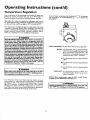
Due to the nature of the typical gas water heater, the water ternr
petature ....
in certain sltuarlons may vary up to 30 DF hight
or
lower at the point of use such as, bathtubs, showers, sink, etc.
Turn the water temperature dial clockwise _./"_)
to decrease
the temperatm'e, or counterclockwise (("- _"_) to increase the
temperature.
This means that when the temperature adjustment dial is set at
the mark approximating 120°t, the actual water temperature at
any hot water tap could be as high as 150°F or as low as 90°E
Any water heater's intended purpose is to heat water. Hot water
is needed for cleaning (bodies, dishes, clothing). Hot water will
present a scald hazard. De,pending on the time element, and the
people involved (normaiadults,'children,
toddlers, elderly,
infirm, etc.) scalding may occur at different temperatures.
AWARNING
HOTTER WATER CAN SCALD:Water heatersareintendedto
producehot water, Water heatedto a temperaturewhichwill
satisfyclotheswashing,dishwashing,and other sani6zJng
needs
canscaldand permanentlyinjureyouuponcontact.Somepeople are more likelyto be permanently injuredbyhot water._an
other_ Theseincludethe elderly,children,
the infirm,or physicaily/mentaEyhandicapped.
If anyoneusinghot water in yourhome
fitsintooneofthesegroupsor ifthere isa localcodeor statelaw
requiringa certain temperaturewater at the hot watertap,then
youmusttake specialprecaution_In additionto usingthe lowest
possible
temperaturesettingthat satisfies
your hot water needs,
a meanssuchas a mixingvalve,shouldbe usedat the hotwater
tapsusedbythese peopleor at the water heater.Mixingvalves
areavailableat plumbingsupplyor hardv_ stores.Followman.
ufacturers instructionsfor installationof the valves.Before
changingthe factory setting on the thermostat, read the
"Temperature Regulation"sectioninthis manual.
PILOT LIGHTING-Set here before attempting to light pilot.
• HOT-Is a thermostat setting of approximately
120°F, which will supply hot water at the
most economical temperatures.
The
temperature adjustment knob can be
turned lower than "HOT" if desired.
A-Is a thermostat setting of approximately
130°E
B-Is a thermostat setting of approximately
140°E
C-Is a thermostat setting of approximately
150°E
AWARNING
I
VERY
Never allowsmall children to usea hot water tap, or to draw [
their own hath water. Never leavea childor handicappedperson unattendedin a bathtub or shower.
HOT-Is
a thermostat
setting of 160°F. It is
recommended
that the dial be set lower
whenever possible.
NOTE: Water temperature range of 1200--140°F
mended by most dishwasher manufacturers.
The thermostat of this water heater has been factory set at its
lowest position, to reduce the risk of scald injury. It is adjustable
and must be reset to the desired temperature setting. The mark
(•) HOT indicative of approximately 120°F is the preferred
starting point. Some states have a requirement for a lower setting. If you need hotter water, follow directions for temperature
adjustment, but beware of the warnings in this section.
recom-
AWARNING
Should overheatingoccur or the gassupplyfail to shut off,
turn OFF' the manual gascontrolvalveto the appliance.
19
Service and Adjustment
Tank (Sediment)
Burner Inspection
Cleaning
Sediment build-up on the tank bottom may create varying
amounts of noise, and if left in the tank will cause premature
tank failure. In some water areas, you may not be able to drain
all sediment deposits by simply draining the tank. In these cases
Mug Erad (part no. 23600) can be used to help remove the sediment deposits. This may be ordered from the Sears Service
Center. For ordering, refer to the Parts Order List section.
AWARNING
I
Do not .usethb applianceif anypart of it hasbeenunderwater, I
Immedtately call a SearsService Technicianto inspectthe I
applianceand to replacethe gascontrol or any part of the I
burnersystemwhichhasbeenunderwater
I
At least once a year a visual inspection should be made of the
main burner andpilot burner. The drawing is for your reference.
Venting System Inspection
You should check for sooting which is not normal and will
impair proper combustion.
At least once a year a visual inspection should be made of the
" venting system. You should look for:
• Obstructions
which could cause improper venting. The combustion and ventilation air flow must not be obstructed.
Damage or deterioration
which could cause improper venti ing or leakage of combustion products.
Rusted flakes around top of water heater.
AWARNING
Chemical vapor corrosionof the flue and vent system may
occurif air for combustioncontainscertain chemicalvapors.
Spray canpropellants,cleaningsolvents,refrigeratorand air
conditioner refrigerants, swimmingpool chemicals,calcium
and sodiumchloride,waxes,bleach,and processchemicalsare
typicalcompoundswhich arepetentially corrosive.
AWARNING
Soot build-upindicatesa problem that requirescorrection I
beforefurther u_. Turn "OFF" gasto water heater and leaveI
I "OFF" until rep_ursare made, .becausefailureto correct .the
I causeof the sootingcan result m a fire or explosioncaning I
I DEATH,SERIOUSBODILYINJUR_,OR PROPERTYDAMAGE. I
AWARNING
Obstructed or deterioratedventsystemsmaypresenta serious
healthHskor asphyxiation.
Burner
In the event your burner needs cleaning,
instructions:
AWARNING
]
Be sure the vent piping is properly connected to prevent|
escapeof dangerousflue gasseswhich could causedeadly
asphyxiation.
Cleaning
use the following
If inspection of the burner shows that cleaning !s required, turn
the gas control knob clockwise (f_%)
to the OFF position,
depressing slightly.
I
NOTE: The knob cannot be turned from "PILOT" to "OFF"
unless knob is depressed slightly. DO NOT FORCE.
AWARNING
If after inspectionof the vent system yon found sootingor
deterioration,something iswrong.Callthe localgasutility.to
correctthe problemand cleanor replacethe flue andventing
beforeresumingopera, on of the water heater,
Loose deposits on or around the burner can be removed by carefully using the hose of a vacuum cleaner inserted through the
access door of the water heater. If the burner needs to be removed
for additional cleaning, call the Sears Service Center to remove
and dean the burner and correct the problem that required the
burner to be cleaned.
20
Service and Adjustment
Drain Valve Washer
Replacement
Draining
The water heater should be drained if being shut down during
freezing temperatures. Also periodic draining and cleaning of
sediment from the tank may be necessary.
•
•
•
•
NOTE: For replacement, use a *_" x *Yd'x %"thick washer
available at your fiearest hardware store. For ordering replacemerit washers, refer to the "Parts Order List" section.
Turn the gas control knob to the "OFF" position.
CLOSE the cold water inlet valve to the water heater.
OPEN a nearby hot water faucet and leave open to allow for
draining.
Connect a hose to the drain valve and terminate to an
adequate drain.
OPEN the water heater drain valve to allow for tank
draining.
NOTE: If the water heater is going to be shut down and
drained for an extended period, the draih valve should be
left open with hose connected allowing water to terminate
to an adequate drain.
Close thedrain valve.
Follow instructions
in the "Filling The Water Heater"
section.
Follow the lighting instructions in the "Lighting" section to
restart the water heater.
Temperature-Pressure
Valve Operation
(cont'd)
Turn "OFF" gas supply to water heater.
Follow "Draining" instructions.
Turning counter clockwise, remove the hex cap below the
screw handle.
Remove the washer and put the new one in place.
Screw the handle and cap assembly back into the drain valve
and retighten using a wrench. DO NOT OVER TIGHTEN.
Follow instructions in the "Filling The Water Heater"
section.
Check for leaks_
Follow the lighting instructions in the "Lighting" section to
restart the water heater.
._AP
ASSEMBLY
Relief
The temperature-pressure relief valve must be manually operated
at least once a year.
TEMPERATURE-PRESSURE
VALVE
Housekeeping
Vacuum around base of water heater for dust, dirt, and lint on a
regular basis.
A WARNING
INSTALLED IN SUITABLE AREA: To insuresufficientventilation and combustionair supply,properclearancesfrom the
water heater must be maintained. See "Facts to Consider
About the Location"section.Combustiblematerialssuch as
clothing,cleaningmaterials,or flammable liquids,etc. must
not be placedagainstor adjacentto the water heater which
cancausea fire.
DISCHARGE PIPE
Failure to install and maintain a new properly listed temperature-pressure relief valve will release the manufacturer
from any
claim which might result from excessive temperature or pressure.
AWARNING
Service
If the temperature-pressure relief valve on the appliance
weepsor dischargesperiodically, this may be due to thermal
expansion. Your water heater may have a check valve
installed in the water line or a water meter with a check
valve.Consultthe SearsService Center for further information. Do not plugthe temperature-pressurerelief vaive.
Before calling for repair service, read the "Start Up Conditions"
and "Operational Conditions" found in the Troubleshooting
Guide of this manual.
If a condition persists or you are uncertain about the operation
of the water heater, let a qualified person check it out.
A WARNING
Contact SEARS Repair Services
(1-800-469-4663).
When checkingthe tempernture-pressurerelief valveoperation, make sure that (I) no one is in front of or aroundthe
outlet of the temperature-pressurereliefvalvedischargeline,
and (2) that the water manuallydischargedwill not causeany
property damage because the water may be extremely hot.
If after manually operating the valve, it fails to completely
reset and continuesto release water, immediately closethe
cold water inlet to the water heater, follow the draining
instructions, and replace the temperature-pressure relief
valve with a new one.
21
at 1-800-4-MY-HOME
Troubleshooting
Guide
Start Up Conditions
CONDENSATION
THERMAL
Whenever the water heater is filled with cold water, a certain
amount of condensation will form while the burner is on. A
water heater may appear to be leakingwhen in fact the water is
condensation, This usually happens when:
• When a new water heater is filled with cold water for the
first time.
Water supply systems may, because of high line pressure, frequent cut-offs, the effects of water hammer and others, have
installed devices such as pressure reducing valves, check valves,
back flow preventers, etc. to control these types of problems.
When these devices are not equipped with an internal by-pass,
and no other measures are taken, the devices cause the water system to be dosed. As water is heated, it expands (thermal expansion) and closed systems do not allow for the expansion of heated water.
i
heaters, particularly high efficiency models where flue temhen gasareburns
in water
pera_res
lower. and water vapor isproduced
When you use large amounts of hot water in a short time
and the refillwater is very cold.
EXPANSION
The water within the water heater tank expands as it is heated
and increases the pressure of the water system. If the relieving
point of the water heater's temperature-pressure relief valve is
reached, the valve w_ll relieve the excess pressure. The temperature-pressure relief valve is not intended for the constant
relief of thermal expansion. This is an unacceptable condition
and must be corrected.
Moisture from the products of combustion condense on the
cooler tank surfaces and form drops of water which may fall
: onto the burner or other hot surfaces to produce a _sizzling" or
"frying" noise.
Excessive condensation can cause pilot outage due to water running down the flue tube onto the main burner and putting out
the pilot.
Because of the suddenness and amount of water, condensation
water may be diagnosed as a "tank leak". After the water in the
tank warms up (about 1-2 hours), the condition should
disappear.
It is recommended that any devices installed which could create
a closed system have a by-pass and/or the system have an expansion tank to relieve the pressure built by thermal expansion in
the water system. Expansion tanks are available for ordering
through the Sears Service Center. Contact the local plumbing
inspector, water supplier, and/or the Sears Service Center for
assistance in controlling these situations.
Do not assume the water heater is leaking until there has been
enough time for the water in the tank to warm up.
Thermal
An undersized water heater will cause more condensation. The
water heater must be sized properly to meet the family's
demands for hot water including dishwashers, washing machines
and shower heads.
Expansion Tank Specifications
Model
Number
Tank Capacity
In Gallons
Dimensions in Inches
Diameter
Length
153.331020
2
8 inches
153.331050
5
11 inches 14_inches
Pipe Fitting
On Tank
12_ inches
_" Male
_" Male
Excessive condensation
may be noticed during the winter and
early spring months when incoming water temperatures ate at
their lowest.
Expansion
Good venting is essential for a gas fired water heater to operate
properly as well as to carry away products of combustion
and
water vapor.
Tank Sizing
Inlet*
Chart
Water Heater Capacity (Gallons)
Water
SMOKEIODOR
Expansion
Tank
Capacity
Needed
It is not uncommon to experience a small amount of smoke and
odor during the initial start-up. This is due to burning off of oil
from metal parts, and will disappear in a short while.
Pressure
40psi
50psi
60psi
70psi
80psi
30
2
2
2
2
2
*Highest recorded inlet water
regulated water pressure.
40
2
2
2
2
5
50
2
2
5
5
5
66
5
5
5
5
5
82
5
5
5
5
5
pressure in a 24 hour period or
NOT]8: Expansion
tanks are pre-charged
with a 40 psi air
charge. If the inlet water pressure is hig_a,er than 40 psi, the
expansion tanks air pressure must be adjusted to match that
pressure, but must not be higher than 80 psi.
22
Troubleshooting
Guide (cont'd)
Operational
HOT
COLD
WATER HEATER
• COLD WATER
, INLET FITTING
SMELLY
(3)
PRESSURE
REDUCING
VALVE WITH
BYPASS
Conditions
WATER
In each glasslined water heater there is installed at least one
anode rod (see "parts section) for corrosion protection of the
tank. Certain water conditions will cause a reaction between this
rod and the water. The most common complaint associated with
the anode rod is one of a "rotten egg smell". This odor is derived
from hydrogen sulfide gas dissolved in the water. The smell is
the result of four factors which must all be present for the odor
to develop:
(I)
EXPANSION
TANK
(3)
a. a concentration of sulfate in the supply water.
b. little or no dissolved oxygen in the water.
c. a sulfate reducing bacteria within the water heater. (This
harmless b_.cteriais non-toxic to humans.)
d. an excess of active hydrogen in the tank. This is caused by :
the corrosion protective action of the anode.
WATER
SHUTOFF
RECOMMENDED INSTALLATION
O_mnou._OUN_nNC)
FLOOR, CEIUNG
WATER HEATER
COLD WATER
INLET FITTING
HOT
Smelly water may be eliminated or reduced in some water heater
models by replacing the anode(s) with one of less active material,
and then chlorinating
the water heater tank and all hot water
lines. Contact Sears Service for further information
concerning
an Anode Replacement Kit #9001453
and this Chlorination
Treatment.
JO,ST,
ETC.
COLD
If the smelly water persists after the anode replacement and chlorination treatment, we can only suggest that continuous chlorination and filtering conditioning equipment be considered to
eliminate the water problem.
STRAPPING
(3)
PRESSURE
REDUCING
VALVEWITH
BY-PASS
{i)
Do not remove the anode leaving the tank unprotected. By
doing so, all warranty on the water heater tank is voided.
INLET COLD
WATER
SHUTOFF
EXPANSION
"AIR"
FAUCETS
_,WARNING
PRESSURE GAUGE
HYDROGEN GAS: Hydrogengascan be producedin a hot
water systemthat hasnot beenusedfor a long periodof time
(generally two weeks or more). Hydrogen gasis extremely
flammable and explosive.To prevent the possibilityof injury
under these conditions,we recommend the hot water faucet
be openedfor severalminutesat the kitchen sinkbeforeany
electricalappliances
whichare connectedto the hot water system are used (suchas a dishwasheror washingmachine).If
hydrogengasis present, there will probablybe an unusual
soundsimilarto air escaping
through the pipeasthe hot water
faucet is opened.There must be no smokingor open flame
nearthe faucetat thetime it isope_
ALTERNATE RECOMMENDED
INSTALLATION
(HORIZONTAL MOUNTING)
STRANGE
IN HOT WATER
SOUNDS
Possible noises due to expansion and contraction
of some metal
parts during periods of heat-up and cool-down do not represent
harmful or dangerous conditions.
Condensation
causes sizzling and popping with the burner area
during heating and coolin[ periods and should be considered
normal. See Condensation
section.
23
Troubleshooting
Operational
(cont'd)
HIGH
Guide (cont'd)
Conditions
TEMPERATURE
SHUT
OFF SYSTEM
WATER
This water heater is equipped with an automatic gas shut offsystern. The high temperature shut off is built into the gas control
valve. This system shuts off the gas supply to the water heater
burners when high water temperatures are present. It is nonresettable. If the high temperature shut off activates, the gas control valve must be replaced. If this were to occur, turn _OFF" the
entire gas supply to the water heater. Contact the Sears Service
Center.
• If lower remperature settings will not lower the water temperature, call the Seats Service Center.
AWARNING
HOTTER WATERCAN SCALI>.Water heatersare intendedto
producehot water.Water heatedto a temperaturewhichwill
satisfyclotheswashin_dishwashing,andother sanitizingneeds
canscaldand permanently injureyou uponcontact.Somepe_
pieare more likelyto be permanentlyinjuredbyhot water than
others.Theseincludetheelderly,children,the intirm,or physicag
ly/mentallyhandicapped.
If anyoneusinghot waterin your home
fitsintooneofthesegroupsor ifthere isa localcodeor statelaw
requiringa certaintemperaturewater at thehot water t_ then
mumust take specialprecaution_In additionto usingthe lowest
_ossibletemperaturesettingthat sa_slles
yourhot water needs,
meanssuchasa mixingvalve,shouldbe usedat the hot water
tapsusedbythesepeopleor at the water heater.Mixingvalves
are availableat plumbingsupplyor hardwarestore_ Followmanufacturersinstructionsfor installationof the valves.Before
changing the factory setting on the thermostat, read the
"Temperature Regulation"
sectionin this manual.
turn "OFF" the manual gascontrol valveto the app ance.
ENOUGH
OR NO
HOT
WATER
Check the pilot flame. It may have gone out. All models have
_o Check
the manual
be sure the
it ispilot.
open.
an opening
behind gas
the shut
outeroffvalve
door fortoviewing
If the pilot is not lit, follow the "Lighting" instructions in this
manual or located above the gas control valve on the water
heater to relight thepilot. If the water was extremely hot and is
now cold, the high limit safety temperature shut off may have
put out the burner and pilot. If the high temperature shut off
activates, the gas controlvalve
must be replaced. Contact the
Seats Service Center.
;
The gas control knob must be turned to the "ON" position.
The temperature adjustment dial may be set too low. See the
"Temperature Regulation" section.
i
Anhe underflred
gas company
water
canheater
check will
the not
gas heat
input water
to seeasifquickly.
it is correct.
Look for leaking or open hot water faucets. Make sure all are
closed.
The cold water inlet temperature may be colder during the winter
months. It will take longer to heat the water and seem like
less hot water.
•
•
HOT
• The temperature adjustment dial may be set too high. See the
_Temperature Adjustment" section.
NOTE: A period of time is necessary after an adjustment
has been made for the water temperature to reach the new
temperature setting.
A, WARNING
I
Shouldoverheating occur or the gas supplyfail to shut off,
NOT
IS TOO
AWARNING
Due to the nature of the typical gas water heater, the
water temperature in certain situations may be hotter
than the thermostat setting.
Short, frequent draws of hot water - especiallywith very
cold incoming water - can shockthe thermostat into brief
operation resulting in hotter and hotter layers of water
closerto the top of the tank.
Changes in hot water usagepatterns or raising the temperature differential between the cut-on of the thermostat and the cold water temperature will usuallyeliminate
the problem.
If you cannot find what is wrong, call the Sears Service Center.
24
Troubleshooting
Guide (cont'd)
Leakage Checkpoints
Use this guide to check a "Leaking"water heater. Many suspected
"Leakers" are not leaking tanks. Often the source of the water
can be found and corrected.
I
_,CAUTION
Read this manual first. Then before checking the water J
heater make sure the gas supply has been turned I
"OFF", and never turn the gas "ON" before the tank is t
If you are not thoroughly familiar with your local gas codes your
water heater, and safety practices,
contact the
Center to check the water heater.
completely
full of water.
J
I
ACAUTION
Never use this water heater unless it is completely filled
with water. To prevent damage to the tank, the tank J
must be filled with water. Water must flow from the hot J
water faucet before turning "ON"
gas to the water
I
Jheater.
O
O
Water at the draft hood is water vapor
which has condensed out of the combustion products. This is caused by
a problem in the vent. Contact the Sears Service Center.
*Condensation
may be seen on pipes in humid
pipe connections may be leaking.
Q'The
weather or
primary anode rod fitting may be leaking.
Small amounts of water from temperature-pressure
relief
valve may be due to thermal expansion or high water
pressure in your area.
O'The
temperarure-pressure
the tank fitting.
Q
Water from a drain valve may be due to the valve opened
slightly.
Q'The
relief valve may be leaking at
drain valve may be leaking at the tank fitting.
Combustion
products contain water vapor which can
condense on the cooler surfaces of the tank. Droplets
form and drip into the fire or run on the floor. This is
common
at the time of startup after installation
and
when incoming water is cold.
0
Water in the water heater bottom or on the floor may be
from condensation,
loose connections, or the relief valve.
DO NOT replace the water heater until a full inspection
of all possible water sources is made and necessary corrective steps taken. Leakage from other appliances, water
lines, or ground seepage should also be checked.
NOTE: To check where threaded portion enters tank,
insert cotton swab between jacket opening and fitting.
If cotton is wet, follow "Draining" instructions in the
"Service and Adjustment" section and then remove
fitting. Put pipe dope or teflon tape on the threads
and replace. Then follow "Filling the Water Heater"
instructions in the "Installation Instructions" section.
25
Parts Order
List
KENMORE ENERGY EFFICIENT m 5 GAS WATER HEATERS
MODEL NUMBERS:
153.334290
153.334390
153.334490
153.334590
40
30
40
50
Gal. Short
Gal.
Gal.
Gal.
!
I
]
21
I
I
!
19
13
9
26
]
......
.._
Parts Order
List (cont'd)
KENMORE ENERGY EFFICIENT TM 5 GAS WATER HEATERS
MODEL NUMBERS:
153.334290
153.334390
153.334490
153.334590
40
30
40
50
Gal. Short
Gal.
Gal.
Gal.
MODEL NUMBERS
KEY
NO.
153.334290
PART DESCRIPTION
9000071
153.334390
153.334490
PART NUMBERS
9000071
9000071
9000279
9000279
9000908
9000908
9000058
9000058
153.334590
9000071
1
2
3
4
Temperature-PressureRelief Valve
Primary Anode Rod
Dip Tube
Drain Valve
5
Drain Valve Washer
(tT/,, x 'Y." x _i" thick)**
9001584
9001584
6
7
Thermocouple Clip
Pilot
F145-0085
8
9
10
42 33900
9000278
F145-0085
9000284
42 33900
9000278
0230130
#37
0230150
#42
0230182
#40
11
12
Thermocouple*
Pilot Tubing w/Fittin_s
Burner Orifice
(Drill Size)
Manifold
Burner
F145-0085
9000284
42 33900
9000278
9002613
9002615
9002411
9002411
9002617
9002411
13
14
Manifold Cover
Outer Door
9002617
9002411
9000358
9000351
9000351
9000351
15
16
Inner Door
Gas Control Valve
17
18
19
20
Temperature Adjustment Knob
Model Rating Plate t
Flue Baffle
Draft Hood
21
#
Ring-Flue Baffle
Owners Manual
#
Mag-Erad
9000707
9000907
9000058
9000284
9000281
F145-1278
F145-1280
0270118
9000300
9000273
9000275
9001584
9000281
F145-1278
F145-1280
0270118
9000281
F145-1278
F145-1280
0270118
9000360
9000360
9000272
9000272
9000279
9000908
9000058
9001584
F145-0085
900O284
42339OO
900O278
0230182
#40
9000281
F145-1278
F145-1280
0270118
9000360
9000272
0002915380
23600
* These parts are also available at most Sears retailstores.
** Also available at most hardware stores.
tReplaced only on return of damaged plate.
# Not Illustrated
Now that you have purchased this water heater, should a need ever exist for repair parts or service, simply contact any SEARS Service Center or
call 1-800-4-MY-HOME (1-800-469-4663). Be sure to provide pertinent facts when you call or visit.
All parts listed may be orderedfrom any SEARS Service Center, most SEARS stores and by calling 1-800-366-PART (1-800-366-7247). If the
parts you need are not stocked locally,your orderwill be electronically transmitted to a SEARS RepairPartsDistribution Center for handling.
The model number of your Gas Water Heater will be found on the model rating plate located near the gas control valve.
WHEN ORDERING REPAIR PARTS, ALWAYSGIVE THE FOLLOWING INFORMATION:
MODEL NUMBER
PART DESCRIPTION
PART NUMBER
NAME OF ITEM
THIS IS A REPAIR PARTSLIST, NOT A PACKING LIST.
27
warranty
a. Adjusting thermostat
b. Lightingpilot
c. Leaksin pipes orfittings
d. Improper venting
e. Condensation
About Your Warranty
THE PRICE OF YOUR WATER HEATER DOES NOT INCLUDE
A FREE CHECKUP SERVICECALL. On Water Heater Installations
Arranged By Sears,Searswarrants the installation.
ON INSTALLATIONS NOT MADE BY SEARS AUTHORIZED
CONTRACTORS:
1. YourSearswarranty appliesto the product only.
2. Searsdoesnot warrant the installation.
3. A charge will be made on service calls due to poor or incomplete
installation.These include:
This manual is in non-technical language.It may help you avoid the
cost of a needless servicecall. Manyservicecalls really arent needed.
Such aswhen:
1.The gas is turned "OFF".
2. The pilot is out.
3. A gas or water leak is due to loose pipe orconnections.
HMITED WARRANTY ON TANKS THAT LEAK
Through five (5) years from the date of purchase, ifa leak occurs in the tank, Sears will furnish, free of charge, a new current model water
heater of closest available capacity and quality. If purchaser does not qualify for free !nstaltation as provided in the One Year Limited Labor
Warranty below, there will be a charge for installation.
If the replacement water heater of closest availablecapacity and quality does not meet current applicable government standards, them will be
a charge for the difference in price between the replacement which does not meet government standards and one which does meet government standards
If the water heater is subjected to commercial, institutional, or industrial use or use in residences of two families or more, the above warranty
coverage for tanks that leak is effective for two years from the date of purchase and the Limited Warranty On Parts below is effective for one
year from the date of purchase.
LIMITED WARRANTY ON PARTS
Through one (1) year from the date of purchase, when your Sears Kenmore water heater is installed and operated in accordance with the
instructions in this manual, ifa part fails due to a failure in materials or workmanship, Sears will furnish a replacement part free of charge.
If purchaser does not qualify for free installation as provided in the One YearLimited Labor Warranty below, there will be a charge for
installation.
ONE YEAR LIMITED LABOR WARRANTY ON WATER HEATER
When your Sears Kenmore water heater is installed by Sears or its licensed subcontractor and is operated in accordance with the instructions
in this manual, Sears will, for one year from the date of purchase:
Install, free of charge, the replacement water heater as provided by the above Limited Tank Leak Warranty.
Repair,free of charge, defects in materials or workmanship of the water heater as pro,,4ded by the above Limited Warranty on Parts.
To obtain warranty service, SIMPLY CALL 1-800-4-MY-HOME (1-800-469-4663).
in the United States.
This warranty
This warranty applies only while this product is in use
gives you specific legal rights and you may also have other rights which vary from state to state.
SEARS, ROEBUCK AND CO., Dept. 817 WA, Hoffman Estates, IL 60179
Sears Installation
Warranty
In addition to any warranty extended to you on the Sears merchandise
involved, which warranty becomes effective the date the merchandise is
installed should the workmanship of any Sears arranged installation prove
faulty within one year, Sears will, upon notice from you, cause such faults to
be corrected at no additional cost to you. If you want this heater professionally installed by Sears contact your Sears Salesperson. They will arrangefor
prompt, quality installation.
Sears Installation Policy
All installation laborarranged by Sears shall be performed in a neat, workmanlike manner in accordance with generally accepted trade practices.
Further,all installations shall comply with all local laws, codes regulations
and ordinances. The customer shall also be protected, during installation,
by insurance relating to property damage, Worker's Compensation and
Public Liability.
If you want this water heater professionally installed by Sears contact your
Salesperson. They will arrange for prompt, quality installation by Sears
authorized conttactors.
delivereddirectlytoyourhome
Call6 am- 11 pm(CST),7 daysa week
1-800-366-PART
Call24 hoursaday,7 daysaweek
1-8OO-4.MY-HOME
(1-800-46S4663)
F
(, -aoo-a_7270)
"rhe_'v_e 51dee¢Ser_."
The model number of your water heater is found on the model rating plate on the front of the water heater.
r,98
Sears, Roebuck
and Co., Hoffman
Estates,
IL 60179
U.S.A.
_029,s3_-0