1
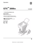
Operation
TexSpray GTX™ 2000
US Patents D502,532; 7,114,664
309915D
- For Water-Based Materials OnlyModel: 248082
Sprayer with Graco Trigger Gun
120 psi (8.27 bar) Maximum Working Air Pressure
120 psi (8.27 bar) Maximum Working Fluid Pressure
Model: 248083
Sprayer with Graco Flex Gun
120 psi (8.27 bar) Maximum Working Pressure
120 psi (8.27 bar) Maximum Working Fluid Pressure
Model: 248084
Sprayer with Graco Pole Gun
120 psi (8.27 bar) Maximum Working Pressure
120 psi (8.27 bar) Maximum Working Fluid Pressure
Read all warnings and instructions.
WLE
308479
310616 model 248082
308603 model 248083 and 248084
309916
Graco Inc. P.O. Box 1441 Minneapolis, MN 55440-1441
Copyright 2003, Graco Inc. is registered to I.S. EN ISO 9001
Warnings
The following Warnings are for the safe setup, use, grounding, maintenance and repair of this equipment.
The exclamation point symbol alerts you to a general warning and the hazard symbols refer to
procedure-specific risks. Refer back to these Warnings.
Warning
WARNING
This symbol alerts you to the possibility of serious injury or death if you do not follow the
instructions.
Caution
CAUTION
Alerts you to the possibility of damage or destruction
of equipment if you do not follow the instructions.
Warnings
Fire and Explosion Hazard
Flammable fumes, such as solvent and paint fumes, in work area can ignite or explode. To help prevent
fire and explosion:
•
•
•
•
•
Use equipment in well ventilated areas only.
Do not fill fuel tank while motor is running or hot; shut off motor and let it cool. Fuel is flammable and
can ignite or explode if spilled on hot surface.
Eliminate all ignition sources; such as pilot lights, cigarettes, portable electrical lamps, and plastic
drop cloths (potential static arc).
Keep work area free of debris, including solvent, rags, and gasoline.
Do not plug or unplug power cords or turn lights on or off when flammable fumes are present.
Carbon Monoxide Hazard
Exhaust contains poisonous carbon monoxide, which is colorless and odorless. Breathing carbon monoxide can cause death. Do not operate in an enclosed area.
Equipment Misuse Hazard
Equipment misuse can cause death or serious injury.
•
•
•
•
•
•
•
•
•
2
Do not exceed maximum working pressure or temperature rating of lowest rated system component. See Technical Data, in all equipment manuals.
Use fluids and solvents that are compatible with equipment wetted parts. See Technical Data in all
equipment manuals. Read fluid and solvent manufacturer’s warnings.
Check equipment daily. Repair or replace worn or damaged parts immediately.
Do not alter or modify this equipment.
Use the equipment only for its intended purpose. Call your Graco distributor for information.
For professional use only.
Route hoses away from traffic areas, sharp edges, moving parts and hot surfaces.
Do not use hoses to pull equipment.‘
Comply with all applicable safety regulations.
309915D
Warnings
WARNINGS
Burn Hazard
Equipment surfaces and fluid that is heated can become very hot during operation. To avoid severe
burns, do not touch hot fluid or equipment. Wait until equipment/fluid has cooled completely.
Pressurized Equipment Hazard
Compressed air can inject in skin. Air tubing rupture can cause injury if disconnected while under
pressure. To reduce risk of injury:
• Never exceed maximum working pressure of any attachment.
• Do not direct airstream at body.
• Follow Pressure Relief Procedure, page 6 whenever you are instructed to relieve pressure, stop
spraying, service equipment, install or clean spray nozzle or disconnect or connect hose.
Cleaning Solvent Hazard with Plastic Parts
Use only compatible water-based solvents to clean plastic structural or pressure-containing parts. Many
solvents can degrade plastic parts to the point where they could fail. Such failure could cause serious
injury or property damage. See Technical Data on page 21 of this instruction manual and in all other
equipment manuals. Read fluid and solvent manufacturer’s warnings.
Personal Protective Equipment
Wear appropriate protective equipment when operating, servicing or when in the operating area of this
equipment to help protect yourself from serious injury, including eye injury, inhalation of toxic fumes,
burns and hearing loss. This equipment includes, but is not limited to:
•
•
•
•
protective eye wear
clothing and respirator as recommended by fluid and solvent manufacturer
hearing protection
gloves
CAUTION
Water or material remaining in unit when temperatures are below freezing can damage pump and/or delay startup.
To insure water and material are completely drained out of unit:
1. Remove material line from sprayer.
2. Tip sprayer to allow material (water) to flow out of pump inlet.
Before adding material or starting unit in cold weather, run warm water through pump.
309915D
3
Component Identification
Component Identification
4
$
9
'
&
%
3
5
=
:
)
6
(
*
-
+
<
WLE
.
/
7
1
0
8
4
309915D
Component Identification
Component Identification
A
Gas Tank
B
Fuel Valve
C
Choke
D
Throttle Lever
E
Engine ON/OFF Switch
F
Nozzle Storage
G
Hopper
H
Hopper Quick Connect
J
Diaphragm Pump
K
Material Outlet Option 1
L
Material Outlet Option 2
M
Air Cooler
N
Gun Air Outlet Quick Connect
P
Air Filter (both sides)
Q
Air Line Quick Connect
R
Engine Starter Cord
S
Motor Lock Knob
T
Material (Pump) Air Pressure Gage and Control Knob
U
Gun Air Pressure Gage and Control Knob
V
Sprayer Quick Connect Air In and Air ON/OFF Valve
W
Pressure Unloader
Y
Gun (see manual 308878)*
Z
Compressor Power Pack
* Reference numbers used in gun illustrations coincide with reference numbers shown in gun manual 308878
309915D
5
Pressure Relief Procedure
Pressure Relief Procedure
IMPORTANT
To reduce the risk of injury, follow this Pressure Relief Procedure whenever you:
• Are instructed to relieve pressure
• Stop spraying
• Service equipment
• Install or clean spray nozzle
• Disconnect or connect hose.
F
OF
ON
E
23
ti3903a
TI3037A
G
TI
1 Turn Engine ON/OFF (E)
switch OFF.
6
2
Open gun air valve (23).
3 Trigger gun. Spray material back into hopper (G).
309915D
Setup
Setup
Preparation
K
L
TI3056A
23
cc
WLE
A
ti3908a
dd
N
ti4003a
4 Connect air and material
hoses to gun. Tighten
securely).
5 Connect one end of material
hose (cc) to material outlet (K
or L) and the other end to gun
material inlet (bb).
6 Open gun air valve (23).
7 Check engine oil level. Add
SAE 10W-30 (summer) or
5W-20 (winter) oil, if necessary.
8 Fill fuel tank (A) (Fueling, page
13).
NOTE: Material plug must be
installed in material outlet (K or
L) you are not using.
Removing & Installing Hopper
G
ti3899a
G
H
H
ti3902a
ti3900a
The hopper (G) can be removed
from cart for cleaning and when
using the Siphon Kit 248112,
available from your Graco
distributor.
309915D
ti3925a
Removing Hopper (G)
Installing Hopper (G)
1 Push down 2 latches on each
side of hopper coupler (H).
2 Position coupler (H) over material outlet and slide hopper (G)
straight down, over the fitting as far as it will go, making sure hopper
bracket is positioned over cart handle rod.
Lift hopper (G) straight up, off
of unit.
Secure latches on each side by pushing them, firmly up, into locked
position.
7
Setup
Compressor Power
Pack
V
S
Q
ti3784a
ti3891a
Removing Compressor Power Pack (Z)
For outdoor use, the compressor
power pack (Z) can be left on the
cart.
1 Disconnect air line quick
connect fitting (Q) from
compressor air quick connect
inlet fitting (V).
2 Loosen motor lock knob (S) by
turning it counter-clockwise,
relieving tension on bracket.
3 Push knob down.
For indoor use, the compressor
power pack (Z) must be separated
from the sprayer and placed
outdoors, A longer air hose (not
provided) must be used to connect
the sprayer to the compressor
power pack (Z). See Running
Compressor Remotely, page 8.
Z
ti3959a
4 The compressor power pack
(Z) slides off the back of the
cart.
8
CAUTION
Running Compressor Remotely
Place compressor power pack
on a hard, level surface where
cooling air can circulate freely
through cooler and a minimal
amount of dirt and dust is drawn
into it. Placing compressor
power pack on a soft, uneven
surface such as dirt, grass or
sand, can plug air cooler (M),
resulting in overheating and
damage to motor.
1 A longer air hose (not
provided) must be used to
connect the sprayer to the
compressor power pack (Z)
when the two components are
separated. (Hose Kit 248117,
2 Attach the longer air hose to
the air line quick connect fitting
(Q) and to the compressor air
quick connect inlet fitting (V).
containing a 50 ft hose is
available from your Graco
distributor.)
309915D
Setup
,
ti3959a
Reinstalling Compressor Power Pack (Z)
Note: For maximum performance
use a 3/8 in. or 1/2 in. inside
diameter hose.
Hose must be rated for:
• 200°F (93°C) maximum
temperature
• 125 psi or greater
1 Disconnect air hose from the
compressor power pack quick
disconnect fitting (dd) and from
the cart air quick disconnect
fitting (V).
2 Inspect cart and compressor
power pack (Z). Remove any
debris or dirt on side rails of
cart and/or compressor power
pack.
3 Using handles, lift compressor
power pack (Z) onto cart
frame.
V
Q
tabs
S
ti3782a
4 Push compressor power pack
(Z) forward, until front edge
meets tabs on cart base.
309915D
5 Lift and turn motor lock knob
(S) until compressor power
pack (Z) is securely attached
to cart.
6 Attach air line quick connect fitting (Q) to compressor air quick connect inlet fitting (V).
9
Setup
Wetting Hose
water
23
closed
ti3903a
ti4005a
ti3898a
Wet inside of hose before each use
to flush out sediment and prevent
texture material from packing out
hose.
1 Pour one (1) gallon (3.8 liters)
of clean water into hopper.
2 Close gun air valve (23).
3 Start engine, page 15. Aim gun
into hopper (G) and trigger gun
to circulate water for a few minutes to wet inside of material
hose.
23
ti4290a
WASTE
4 Trigger gun into waste pail until
hopper no longer contains
water.
10
TI
5 Open gun air valve (23) to
relieve compressor air.
309915D
Setup
Wetting System
ti3905a
TI
CAUTION
1 Fill hopper (G) with prepared
texture material.
Do not mix material in hopper.
Mixing material in hopper can
damage hopper, result in an
inconsistent mix and packout can
occur.
CAUTION
2 Install tip. See Nozzle Selection
Chart, page page 16.
3 Open gun air valve (23) to
relieve air pressure.
Do not allow material to flow out of
gun when air valve (23) is closed or
material packout in needle can
occur.
T
U
TIA
ti3910a
NOTE: If spraying a simulated
acoustic and coarse aggregate
material, disconnect hose at gun,
prime pump and hose and circulate
material back into hopper for 10
seconds. Turn off pump. Install gun
and tip.
309915D
4 Inspect hose for kinks which
could restrict fluid flow.
5 Trigger gun into a pail. When
texture material appears at tip,
move gun to hopper and circulate until there is a solid stream
of texture material.
6 See System Adjustment, page
17 for proper spray pattern and
pump and gun adjustments.
7 On the sprayer, adjust gun air
pressure (U) and pump air
pressure (T) to achieve desired
results.
11
Setup
Mixing Material
ti3906a
ti3907a
CAUTION
Do not use any solvent-based
materials.
Use water-based materials
only.
Proper material mixture is
essential. The pump will not
operate if material is too thick.
NOTE: For best results, mix
material in a separate container
and pour it into hopper.
2 Agitate to a smooth, lump-free
consistency.
3 After texture material is thoroughly mixed, gently set ball
end of Material Thickness
Gauge on surface of mixture.
5 If the ball does not sink completely into the mixture within
10 seconds, add more water,
agitate and try again.
NOTE: Thicker materials that do
not pass the Material Thickness
Gauge test, can be used. Before
spraying thicker materials test
pump performance first. If the
material is too thick you will not
achieve good results.
1 Slowly add one bag of texture
to clean water as instructed on
bag.
For best results do not use partial
bags.
READY
ADD WATER
ti2498a
NOTE: For an accurate test, be
sure gauge is completely dry and
clean every time it is used.
12
4 Observe ball on the material.
When the material is thin
enough to spray, the ball will
sink completely into the mixture.
309915D
Setup
Fueling
E
OF
F
ON
TI3037A
A
ti3962a
ti3908a
Fuel Specifications
Refueling Procedure
•
1 Shut OFF engine. Remove fuel
tank cover.
2 In a well ventilated area, add
unleaded automotive gasoline
to fuel tank. Leave 1/2 (13 mm)
at top of tank for gasoline
expansion.
Use automotive gasoline with a
pump octane number of 86 or
higher. If engine knocks or pings,
use a higher octane fuel.
•
Unleaded fuel minimizes combustion chamber deposits.
•
If using gasohol, it may contain
no more than 5% methanol, and
must have methanol cosolvents
and corrosion inhibitors.
3 Tighten fuel cap firmly.
Fuel vapor or spilled fuel can
ignite. If any fuel is spilled,
make sure are is dry before
starting engine.
NOTE: Tank capacity is 0.95
gallon (3.6 liter).
•
Close black fuel shutoff lever
whenever you are transporting
sprayer to prevent fuel from
flooding engine.
•
Keep sprayer upright and level
when operating and when transporting. This prevents crankcase
oil from leaking into combustion
chamber, which makes start up
very difficult.
Do not smoke or allow flames
or sparks in area where engine
is refueled or where gasoline is
stored.
NOTE: The HONDA engine
warranty does not cover damage
resulting from the use of gasoline
containing alcohol.
•
CAUTION
Do not use oil and gasoline mixtures or contaminated gasoline.
Operation
Characteristics
W
Start
Run
23
CLOSED
7136A
OPEN
ti3909a
CAUTION
Always start system with
compressor air relieved. See
Pressure Relief Procedure,
page 6.
309915D
CAUTION
•
Air bleeds from gun nozzle when
gun valve (23) is open. Close air
valve (23) to stop air when priming system. See System Adjustment, page 17, for more gun
characteristics.
Before pulling engine starter rope
(R), pressure unloader valve (W)
must be moved up to START
position. Move valve down to RUN
position after motor has started.
Allow engine to cool a minimum
of 10 minutes or use an
insulating glove, before
disconnecting air lines or
attempting to restart.
13
Setup
K
L
T
23
closed
U
plug
ti4005a
ti3787a
14
•
Always have material outlet
plug installed in opening (K or
L) that you are not using when
there is material in hopper. If
plug is removed, hopper will
drain out.
•
also
Always have material hose
installed in the opening (K or L)
when there is material in hopper. If hose is removed, hopper
will drain out through pump.
ti3910a
•
Compressor air pressure is controlled with the pressure control
knob (T) and displayed on gage.
•
Gun air pressure is regulated using air pressure control on sprayer (U)
as well as gun air valve located on gun handle (23). The site gage on
sprayer enables duplication of air pressure setting. The gun air valve
(23) allows for additional air pressure adjustment.
309915D
Startup
Startup
Starting Gas Engine
D
E
OFF
ON
TI3065A
TI3064A
TI3067A
B
C
TI3062A
1 Move fuel valve (B) to open
2 Move choke (C) to closed
3 Set throttle (D) to fast
4 Set engine (E) switch ON
W
R
Start
D
ti3961a
Run
C
W
Start
ti3316a
Run
ti3909a
TI3064A
ti3909a
5 Flip up pressure unloader
valve (W) to START position.
309915D
6 Pull starter cord (R).
7 After motor starts, move choke
(C) to open and pressure
unloader (W) down, to RUN
position.
8 Set throttle (D) to desired setting.
15
Spray Techniques
Spray Techniques
Nozzle Selection
IMPORTANT
Keep pump and hose clean when switching between simulated acoustic, knockdown and orange
peel applications. A dirty pump can release particles of texture into the finish.
Nozzle Selection
Application
Nozzle Orifice2
Nozzle No.
Air Volume1
Fog
1/8 in.
3
high
3/16 in. (fine)
4
1/4 in. (fine to med)
6
5/16 in. (coarse)
8
Orange Peel
1/8 to 3/16 in.
3-4
medium to high
Splatter Coat
1/4 to 5/16 in.
6-8
low - medium
Knock-down
5/16 in.
8
low
Simulated Acoustic
1 Control
2For
16
medium to high
air volume with gun air flow valve (31).
more material volume, try a larger-orifice tip.
309915D
Spray Techniques
System Adjustment
A
A
ti4004a
ti3999a
ti4000a
1 Open air valve (A).
2 Test spray pattern on cardboard. Hold gun 18 to 30 in.
(457 to 762 mm) from surface.
Use this spray distance for
most applications. Overlap
each stroke 50% in a circular
motion.
3 Adjust air valve (A) to achieve
uniform, round spray pattern. It
may be necessary to change
spray nozzle to achieve
desired spray pattern.
NOTE: Keep a small amount of air
flowing through air line and gun tip
to prevent material from backing up
needle
B
C
4 To select correct nozzle for
your applications, consider
size of aggregate in material
and coarseness of spray pattern. Remember the larger the
nozzle, the larger the pattern.
See Nozzle Selection, page
16.
•
More air produces a finer finish,
less air a coarser finish.
309915D
ti4338a
When adjusting flow adjustment
nut (B), release trigger (C), then
adjust.
If adjusting while triggered,
needle will turn but provide no
adjustment.
Check material consistency
often. Material may thicken as it
sits and slow down production or
affect spray pattern. Thin with
water as needed to maintain
proper consistency.
If flow adjustment nut will not
turn, check to see if it is:
• set to maximum adjustment, or
• if there is material on threads.
Clean threads as needed.
17
Spray Techniques
A
B
D
ti4006a
ti4000a
ti4339a
Material Flow
Adjustment
•
•
For a lighter spray pattern,
decrease material pressure at
sprayer.
For a heavier spray pattern,
increase material pressure at
sprayer.
Air Flow Adjustment
•
Trigger gun.
•
To decrease air flow, close air valve
(A) (clockwise).
•
To increase air flow, open air valve
(A) (counter-clockwise).
NOTE: Keep a small amount of air
flowing through air line and gun tip to
prevent material from backing up needle
Preventing Material
Surge at Gun Trigger
Pressure will build up in system when
you stop triggering gun. To prevent
material surge at beginning of spray
pattern,
•
when you first pull trigger, point
gun away from surface you are
spraying.
•
hold gun away from surface and
gradually work your way closer to it.
•
trigger gun as little as possible
For Continuous
Spraying
•
Engage trigger lock (D) to hold
trigger open and reduce fatigue.
Compressor Power
Pack Performance
•
18
.Reduce engine RPM (throttle).
Running the engine slower will
reduce pressure surging, heat
and noise.
•
The pressure unloader, unloads
less frequently, if the engine
RPM (throttle) is set lower.
309915D
Shutdown and Cleanup
Shutdown and Cleanup
CAUTION
English
• Turn off sprayer if you are going to stop spraying for 5 minutes or longer.
• Before removing material hose relieve pressure and material is not in hose.
• To keep sprayer in good operating condition, always clean it thoroughly and prepare it properly for storage.
• If water freezes in sprayer, damage may occur. Inn cold weather store sprayer where it will not freeze.
ti4288a
When you have finished spraying:
1 Relieve Pressure, page 6.
2 Fill material hopper with 2-4
gallons of clean water.
309915D
3 Spray inside material hopper
to circulate water through gun
and hose. While circulating
water, use gun to clean material hopper.
Spray water into waste bucket to
empty material hopper.
4 Follow Pressure Relief, page
6.
NOTE: A soft brush can be used to
loosen dried on material
19
Maintenance
Maintenance
Component
Task
Frequency
Engine
Check Oil
Daily
Hoses
Check for wear and/or damage
Daily
Drain system of all water
After each use
Air and Material Hose Connections
Add a few drops of light oil
After each days use
Diaphragm Pump
Lubricate
Remove hose from pump air inlet and
add 2 drops of machine oil to air inlet
after every 500 hours of operation (or
monthly).
Flush
Before storing
Thread Connections
Before each use check to make sure all
connections are tight and leak free
Every two months, retorque all threaded
connections
Compressor Air Filter
20
Clean
Monthly
Unloader Muffler
Clean
Monthly
Gun
Clean
After each use
Add a few drops of light oil to flow
adjustment
After each use
309915D
Technical Data
Technical Data
Maximum working air pressure
Maximum working fluid pressure
Air pressure operating range
Compressor specifications
Air Displacement
Air Delivery
Engine
Gas capacity
Oil capacity
Hopper capacity
Maximum deliver with texture material
Dimensions
Length
Width
Height
Weight
With hoses or gun
Without hoses and gun
Without hoses and gun and compressor power
pack
Compressor power pack only
Wetted parts
Sound data
Sound pressure level*
Sound power level#
120 psi (8.27 bar)
120 psi (8.27 bar)
25 to 120 psi (1.7 to 8.27 bar)
Oilless compressor
24 CFM (680 lpm)
12 CFM @ 100 psi (340 lpm @ 6.9 bar)
5.5 HP Honda OHV
0.95 US gallons (3.6 liters)
0.63 US quarts (0.60 liters)
17 US gallons (64 liters)
4.0 gpm (15.14 lpm)
38 in. (965 mm) with handles
24 in. (610 mm)
40 in. (1016 mm)
185 lb (83.91 kg)
165 lb (74.84 kg)
90 lb (40.82 kg)
75 lb (34.02 kg)
PVC, zinc plate CS, Buna-N, aluminum, brass,
polyethylene, SST, UHMW, Delrin
92 db(A)
106.3 db(A)
*Measured while spraying at 1 m.
#Measured per ISO-3744
309915D
21
Warranty
Warranty
Graco warrants all equipment referenced in this document which is manufactured by Graco and bearing its name to be free from defects in
material and workmanship on the date of sale to the original purchaser for use. With the exception of any special, extended, or limited warranty
published by Graco, Graco will, for a period of twelve months from the date of sale, repair or replace any part of the equipment determined by
Graco to be defective. This warranty applies only when the equipment is installed, operated and maintained in accordance with Graco’s written
recommendations.
This warranty does not cover, and Graco shall not be liable for general wear and tear, or any malfunction, damage or wear caused by faulty
installation, misapplication, abrasion, corrosion, inadequate or improper maintenance, negligence, accident, tampering, or substitution of
non-Graco component parts. Nor shall Graco be liable for malfunction, damage or wear caused by the incompatibility of Graco equipment with
structures, accessories, equipment or materials not supplied by Graco, or the improper design, manufacture, installation, operation or
maintenance of structures, accessories, equipment or materials not supplied by Graco.
This warranty is conditioned upon the prepaid return of the equipment claimed to be defective to an authorized Graco distributor for verification of
the claimed defect. If the claimed defect is verified, Graco will repair or replace free of charge any defective parts. The equipment will be returned
to the original purchaser transportation prepaid. If inspection of the equipment does not disclose any defect in material or workmanship, repairs will
be made at a reasonable charge, which charges may include the costs of parts, labor, and transportation.
THIS WARRANTY IS EXCLUSIVE, AND IS IN LIEU OF ANY OTHER WARRANTIES, EXPRESS OR IMPLIED, INCLUDING BUT NOT LIMITED
TO WARRANTY OF MERCHANTABILITY OR WARRANTY OF FITNESS FOR A PARTICULAR PURPOSE.
Graco’s sole obligation and buyer’s sole remedy for any breach of warranty shall be as set forth above. The buyer agrees that no other remedy
(including, but not limited to, incidental or consequential damages for lost profits, lost sales, injury to person or property, or any other incidental or
consequential loss) shall be available. Any action for breach of warranty must be brought within two (2) years of the date of sale.
GRACO MAKES NO WARRANTY, AND DISCLAIMS ALL IMPLIED WARRANTIES OF MERCHANTABILITY AND FITNESS FOR A
PARTICULAR PURPOSE, IN CONNECTION WITH ACCESSORIES, EQUIPMENT, MATERIALS OR COMPONENTS SOLD BUT NOT
MANUFACTURED BY GRACO. These items sold, but not manufactured by Graco (such as electric motors, switches, hose, etc.), are subject to
the warranty, if any, of their manufacturer. Graco will provide purchaser with reasonable assistance in making any claim for breach of these
warranties.
In no event will Graco be liable for indirect, incidental, special or consequential damages resulting from Graco supplying equipment hereunder, or
the furnishing, performance, or use of any products or other goods sold hereto, whether due to a breach of contract, breach of warranty, the
negligence of Graco, or otherwise.
ADDITIONAL WARRANTY COVERAGE
Graco does provide extended warranty and wear warranty for products described in the “Graco Contractor Equipment Warranty Program”.
TO PLACE AN ORDER, contact your Graco distributor, or call 1-800-690-2894 to identify the nearest distributor.
All written and visual data contained in this document reflects the latest product information available at the time of publication.
Graco reserves the right to make changes at any time without notice.
MM 309915
This manual contains English
Graco Headquarters: Minneapolis
International Offices: Belgium, Korea, China, Japan
GRACO INC. P.O. BOX 1441 MINNEAPOLIS, MN 55440-1441
http://www.graco.com
Written in USA 10/2003, Rev 10/2006
22
309915D