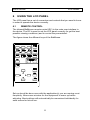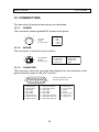
1
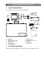
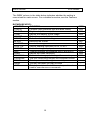
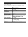
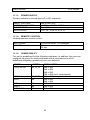
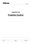
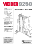
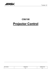
USER
GUIDE
IMPACT 64
Not the actual front page
801.200A
USG/064/AE-A
14.06.95
USER GUIDE
IMPACT 64
USER GUIDE
LCD PANEL
2
USER GUIDE
LCD PANEL
TABLE OF CONTENTS
INTRODUCTION ..................................................................................... 5
MAIN FEATURES .................................................................................... 5
SUPPLIED MATERIAL............................................................................. 6
OPTIONAL MATERIAL ............................................................................ 6
SETTING UP THE LCD PANEL ............................................................... 7
COMPUTER............................................................................... 8
MOUSE...................................................................................... 9
USING THE LCD PANEL ....................................................................... 11
REMOTE CONTROL................................................................ 11
FRONT PANEL ........................................................................ 13
CONNECTORS ........................................................................ 13
FEATURES............................................................................................ 14
PRACTICAL HINTS AND TIPS............................................................... 18
MAINTENANCE ..................................................................................... 20
SERVICE............................................................................................... 20
TECHNICAL DATA ................................................................................ 21
CONNECTORS ..................................................................................... 24
FCC STATEMENT ................................................................................. 25
ENVIRONMENTAL STATEMENT........................................................... 26
SERVICE INFORMATION...................................................................... 27
CONNECTION LAYOUT ........................................................................ 28
(Foldout Page)
3
USER GUIDE
LCD PANEL
This publication is printed on recycled paper.
The information contained in this user guide is preliminary, and the products described
herein are subject to change without prior notice.
The symbols
and
are used in this publication to indicate
Warning and Note respectively.
4
USER GUIDE
1
LCD PANEL
INTRODUCTION
The LCD panel is a state of the art projection device that can be connected
to most computers.
The ability to display a multitude of greyshades simultaneously, makes it
the ideal choice for presenting computer generated text and graphics.
Applications include presentations, software training, educational use,
advertising, information boards and other situations where a small or
large audience shares information.
2
MAIN FEATURES
-
64 greyshades
BatMouse™ , infrared remote mouse
User settings memorized
Individual settings for all modes
Correct VGA text
Infrared remote control
Housing footprint fits OHP glass exactly
Low weight
Intelligent Safecool system
False light blocking
4 meters Y-cable
5
USER GUIDE
3
LCD PANEL
SUPPLIED MATERIAL
A complete set includes the following components :
1.
2.
3.
4.
5.
6.
7.
4
LCD Panel
VGA-Cable
Cable-Adapt. MACII mon
Cable-Adapt. MACII comp.
Mouse Cable
Mouse Adapter PC
Mouse Adapter Mac
8.
9.
10.
11.
12.
13.
Power -5, 12, 5 V
Power Cable
BatMouse Remote Control
Batteries
Attachè Case
User Guide
OPTIONAL MATERIAL
Optional cables and adapters are available for special computer sources.
6
USER GUIDE
5
LCD PANEL
SETTING UP THE LCD PANEL
Switch off all equipment before connecting the components. Be aware of
static electricity that may build up, especially in the dry season and when
operating on synthetic carpets. Discharge any static electricity by touching
a metallic surface before you start.
Place the LCD panel on top of a transmissive overhead projector (OHP).
Select a high intensity type projector, for instance 400W. Best results are
obtained in a dimmed room with no direct sunlight shining in. Using the
LCD panel on some metal halide OHP’s may cause visible flicker. This will
not harm the LCD panel.
The following are guidelines for first time set-up:
• Connect the cables and power supply as described in the rear foldout
page (see Connection Layout).
• Attach power to the LCD panel, turn the overhead projector and
computer on.
Do not switch on the OHP unless the LCD panel is powered, as
this may cause permanent damage.
If you are going to use a mouse, make sure to power the LCD panel first.
For more information on set-up see the following sections on Computer
and Mouse.
7
USER GUIDE
5.1
LCD PANEL
COMPUTER
Connect the LCD panel, computer, monitor and power supply as shown in
the rear foldout.
Connect the VGA cable (1) between the LCD panel and the computer. Use
the Y-split on the computer end to connect the monitor.
If you have a Macintosh, EGA, CGA or NEC computer, insert applicable
adapters (4) and (5) as described in the table below.
Connect the power supply to the LCD panel (3).
APPLICABLE ADAPTERS :
COMPUTER
VGA/SVGA
EGA/CGA*
MACII c../v../LC/ Quadra/Powerbook/ Duo etc.
NEC 9801
ADAPTER
None
EGA/CGA (option)
MACII (640 x 480)
(included)
NEC 9801(option)
* Computer only, monitor not available
TO SET UP FROM THE BATMOUSE REMOTE CONTROL :
STEP OPERATION
1
Press RESET for default settings
2
Adjust TUNE for a stable image
3
Press POSITION, then use cursor keys to position the image
4
Adjust CONTRAST as desired
8
USER GUIDE
5.2
LCD PANEL
MOUSE
See the rear foldout when setting up.
Connect the mouse to the LCD panel using the appropriate adapter (6) as
described in the table below. Then connect the adapter (6) to the mouse
cable at the computer end. Finally, connect the mouse cable to the LCD
panel (2).
For the computer to recognise the mouse, connect all cables and
power on the LCD panel before power is applied to the
computer.
A Y-split is provided with the PC and MAC adapters that enables parallel
use of the local computer mouse and the remote mouse.
The local and remote mice should not be operated
simultaneously, as this may lead to unpredictable positioning of
the mouse pointer.
If you have a Macintosh, make sure to connect your Mac mouse adapter
via the keyboard.
The optional PS/2 adapter does not have a Y-split.
APPLICABLE ADAPTERS :
MOUSE
Microsoft 2 key compatible (9 pin serial port)
PS/2 compatible mouse
Macintosh ADB-bus mouse
ADAPTER
PC
PS/2
MAC
USING THE BATMOUSE :
STEP OPERATION
1
Control mouse pointer directly with the cursor keys
2
Press LEFT to activate (emulates the left mouse key)
3
Press DRAG to tag an object, move it using the cursor keys,
then press DRAG again (or wait 5 seconds) to release the
object.
4
Press RIGHT if your application requires emulation of the
right mouse key.
The centre key of three-key mice is not emulated.
9
USER GUIDE
LCD PANEL
If double-click does not work properly, try to adjust the double-click rate
within the computer application in use. To activate the pull-down menus on
a Macintosh computer, use the DRAG key instead of the left mouse key!
10
USER GUIDE
6
LCD PANEL
USING THE LCD PANEL
The LCD panel has a set of connectors and controls that you need to know
in order to operate the device correctly.
6.1
REMOTE CONTROL
The infrared BatMouse remote control (RC) is the main user interface to
the device. The RC is used to set the LCD panel correctly (to get the best
possible viewing conditions) and to control the presentation.
The figure shows the different keys of the BatMouse.
Set-up should be done once with the application(s) you are running most
frequently. Allow some minutes for the equipment to warm up before
adjusting. Most settings will automatically be memorized individually for
each source for future use.
11
USER GUIDE
LCD PANEL
The 'MEM' column in the table below indicates whether the setting is
memorized for each source. For a detailed overview, see the Features
section.
BATMOUSE KEYS :
CONTROL
FUNCTION
CONTR
Contrast (ratio between light and dark colors)
BRIGHT
Brightness (whiteness)
TUNE
Adjusts the stability of the image
ON/OFF
Turns the panel on/off
RESET
Defaults to standard settings
BLACK
Blackens the screen
INVERSE
Inverts the image
PALETTE
Selects shading resolution of 64, 16 or 2
FREEZE
Holds the image displayed
MAC
Toggles between the standard MACII and the LC
FREQ
Adjusts the video frequency
POSITION
Controls the image positioning with cursor keys
CURSORS
The four cursor keys control the computer mouse
RIGHT
This key emulates the right mouse key
DRAG
This key emulates the drag function
LEFT
This key emulates the left mouse key and is also
used to execute menu commands
12
MEM
YES
YES
YES
NO
NO
YES
NO
YES
YES
YES
-
USER GUIDE
6.2
LCD PANEL
FRONT PANEL
The front panel keyboard consists of a subset of the remote control keys.
ON/OFF
CONTROL
TUNE
BRIGHT
RESET
ON/OFF
6.3
TUNE
BRIGHT
RESET
FUNCTION
Adjusts the stability of the image
Adjusts the brightness (whiteness) of the image
Defaults to factory settings
LED activity indicator
CONNECTORS
All connectors are positioned on the right hand side of the LCD panel. See
the technical data section for pinouts of the various connectors.
MOUSE
COMPUTER
POWER
Do not connect any other devices with similar plugs to the
connectors of the LCD panel, as this voids any warranty and
may cause permanent damage to the device.
CONNECTOR
POWER
MOUSE
COMPUTER
FUNCTION
Low voltage power supply
Universal mouse connector
Combined connector for analog and digital RGB
13
USER GUIDE
7
LCD PANEL
FEATURES
The LCD panel has a variety of different features implemented. This
chapter explains each feature in detail.
7.1.1
INTELLIGENT SAFECOOL SYSTEM
The fan operation is controlled by the overhead projector light (OHP). This
safety feature ensures that the fan is always operating as long as the OHP
is turned on. When the OHP is turned off, the fan automatically stops to
minimize noise.
The power supply must be attached to the panel for the fan to
work properly.
7.1.2
SET-UP MEMORY
The user controlled set-up, that usually is done when the panel is
connected to a new computer, is automatically memorized for future use.
The set-up information is stored in a non-volatile memory approximately 5
seconds after the last key is pressed.
The memory can store 40 different sources/modes. Several sources are
predefined, while the remaining are available for customer set-up of
sources. See the Technical Data section for compatibility.
Custom sources are stored only if their sync pattern differs from any of the
previous selections. The panel automatically selects a new memory
location.
Most settings are stored individually for each mode, including contrast,
brightness, tune etc. See the remote control table above.
7.1.3
COLOR MAPPING
A color-to-monochrome mapping scheme much like the one used in
monochrome television sets is applied. This means that a color image of a
human face appears natural in black and white. When using 64 shades,
usually no information is lost, even in color intensive applications.
14
USER GUIDE
LCD PANEL
7.1.4
SVGA
SVGA in 800 x 600 mode is compressed both horizontally and vertically to
640 x 480 resolution. This feature is convenient when displaying irregular
images (like pictures, scanned images and coarse graphics).
Regular images (patterns, text and fine line graphics) may look distorted
due to the downsizing. In this case, we recommend setting up the
computer in 640x480 mode for a precise image.
7.1.5
VGA TEXT
VGA text is compressed correctly from 720 x 400 to 640 x 400 mode when
the image is positioned correctly. The characters maintain their shape, as
every ninth pixel is dropped horizontally between each character.
7.1.6
CONTRAST
The contrast of an image is defined as the relation between dark and light
colors. An image of high contrast is often regarded as ‘hard’, as compared
to the ‘soft’feeling of a low contrast image. Low contrast is recommended
for long term viewing, while high contrast is used to enhance details. Use
the CONTR keys on the remote control (RC) to adjust the contrast. Also
see Brightness. The contrast setting is stored individually for each mode.
7.1.7
BRIGHTNESS
The brightness is the amount of white in an image. The brightness is
adjusted to the ambient lighting conditions. Use the BRIGHT keys to adjust
brightness. See also Contrast. The brightness setting is stored individually
for each source.
7.1.8
TUNE
This feature enables a stable image. An unstable image can be seen as
sideways instability or ‘swimming’. Press TUNE until a stable image is
achieved. The setting is stored individually for each source.
7.1.9
ON/OFF
This switch controls the operation of the panel. When switched on, all
functions are active. When switched off, the automatic fan control is still
operating, but the image is turned white. The ON/OFF switch is a toggle
key.
15
USER GUIDE
LCD PANEL
7.1.10 RESET
This feature resets most controls to standard settings. See the 'MEM'
column in the remote control description, where YES indicates a standard
resettable setting. RESET will only reset the active mode.
A fundamental master reset may be performed by pressing all four front
panel keys simultaneously for approx. 5 seconds. All settings will return to
factory defaults. Do not perform a master reset unless it is really required.
This operation will also erase all custom sources and modes that have
been memorized.
7.1.11 BLACK
Use the BLACK key if you temporarily want to suspend the display of
images. The BLACK key is a toggle function and the screen goes black
when activated. Any key pressed will release BLACK.
7.1.12 INVERSE
This option inverts the image. This setting is not memorized.
7.1.13 PALETTE
The PALETTE is by default set to display 16 greyshades regardless of
application. Some applications may however look better with a different set
of shades. Pressing PALETTE will cycle between 2, 16 and 64 greyshades.
This setting is retained individually for each mode. RESET defaults to 16
shades.
7.1.14 FREEZE
Press the FREEZE button to lock the image displayed. This feature is
useful if you want to make changes locally on your computer that should
not be seen by the audience. Press FREEZE once more to resume on-line
operation. Any other key pressed will also release FREEZE.
7.1.15 MAC
The MACII series of computers are equipped with slightly different 640 x
480 graphics adapters that need manual set-up to work correctly. Press
this key to toggle between the basic MACII and the LC mode. The setting
is retained.
16
USER GUIDE
LCD PANEL
7.1.16 FREQUENCY
This setting is usually not changed by the user. It is however provided in
case of adaptation to special graphics adapters that are close to those in
the compatibility list. A bad frequency setting can be seen as an image too
wide or too narrow, combined with vertical, unstable bands. Press the
FREQUENCY keys left or right to correct the image. The setting is stored
individually for each source.
7.1.17 POSITION
Due to minor variations in graphics adapters, the horizontal and vertical
position may need adjustment. Press POSITION, then use the cursor keys
to position the image. The position is stored.
7.1.18 MOUSE
The remote control (RC) employs a unique mouse functionality that
enables full mouse control of your PC, PS/2 or Macintosh computer. By
default, the cursor keys of the remote control emulate the mouse.
The LEFT and RIGHT keys emulate the left and right keys on a standard
two-key mouse. For Macintosh computers, the right key is not used.
The DRAG key is used to emulate the click-and-hold action. To move an
object, position the mouse cursor, press DRAG to tag the object, position
the object as desired using the cursor keys, then press DRAG again to
release the object. DRAG is automatically released 5 seconds after the last
key is pressed. The DRAG key is used to activate the pull-down menus on
the Macintosh.
17
USER GUIDE
8
LCD PANEL
PRACTICAL HINTS AND TIPS
This is a list of what to do when things go wrong. Check the symptoms
carefully if you experience any problem. The cure may be at your hands!
Always press the RESET key and observe that the LED on the
LCD panel is flashing. This indicates that the LCD panel receives
signals from the remote control..
The LCD image is completely white
- Check the ON/OFF key on the remote control
The LCD image is completely black
- Check the BLACK switch
- Check the CONTRAST and BRIGHTNESS settings
- Check if the cables are connected and that power is on
(LED on front panel)
The LCD image is too dark or too light
- Check the CONTRAST and BRIGHTNESS settings
- Try the RESET key
Some shades are unstable or flickering
- Try to adjust the CONTRAST or possibly TUNE
The whole LCD image appears unstable or misplaced
- Try to adjust the TUNE or POSITION
- Alternatively, you are most probably connected to an
incompatible computer (see the Compatibility section) or video
card. See the Features section for frequency adjustment and
positioning
The cooling fan is not working
- The fan operation is controlled by the overhead projector light
Is the OHP turned on?
- Check that the power supply is attached
- Do not use the LCD if the fan appears defective, as overheating
may occur
18
USER GUIDE
LCD PANEL
The remote control is not working
- Check if the batteries need replacement
- Be sure to point at the projection screen or directly at the IR eye
in the front of the LCD panel
- You may be too far away from the panel (max. distance 7 m/
23 feet)
The mouse is not working
- Make sure that the LCD panel is switched on first
- Remember to connect the mouse cables before the computer is
switched on
- Check if the mouse cable and adapter are properly connected
19
USER GUIDE
9
LCD PANEL
MAINTENANCE
From time to time, the housing and protection glasses may be cleaned
with a damped, non abrasive cloth, possibly using a mild detergent to
remove spots.
The upper protection glass is not removable, as it only needs cleaning
from the outside (the inside is sealed to the LCD module).
The lower protection glass can be removed for cleaning. Place the unit
upside-down on a soft cloth to avoid scratches. Using two fingers, press
the protection glass out of the guide rail and slide out. Replace the glass
after cleaning.
Be careful not to touch or drop any objects inside the housing as
this may cause serious damage.
10 SERVICE
This product contains no user serviceable parts. Attempts to modify
mechanics or electronics inside the housing will violate any warranties,
and may be hazardous.
If for any reason the product fails to work properly, first check the previous
chapter on hints and tips. If things still do not work, please contact your
dealer for technical support. Prepare a list of the symptoms you observe to
make the diagnosing easier for your dealer. Remember to include all
cables and power supply when returning the goods.
If the problem cannot be solved by the dealer, please see the Service
Information section.
20
USER GUIDE
LCD PANEL
11 TECHNICAL DATA
The technical data may change without prior notice in order to improve the
product performance.
The apparatus is designed for indoor use and should not be
operated outside the general environmental limits, as this may
lead to permanent damage and violation of any warranties.
11.1.1
GENERAL ENVIRONMENTAL LIMITS
STORAGE TEMPERATURE
STORAGE HUMIDITY
OPERATING TEMPERATURE
OPERATING HUMIDITY
-20 ~ 60 C (-4 ~ 140 F)
10 ~ 90 percent relative humidity,
non condensing
10 ~ 40 C (50 to 104 F)
20 ~ 80 percent relative humidity
Allow for a slow acclimatization, after storing at extreme temperatures and
humidities, to avoid condensation. Should condensation appear, operate
for some time on an OHP, as the heat generated will evaporize the water.
21
USER GUIDE
LCD PANEL
11.1.2 DISPLAY UNIT
Monochrome display unit connecting directly to external video sources.
SIZE
WEIGHT
POWER
LCD CELL
GREYSHADES
RESPONSE TIME
CONTRAST RATIO
PIXEL RESOLUTION
SCREEN DIAGONAL
MOUSE COMPATIBILITY
VIDEO FREQUENCY
HORIZONTAL SYNC
VERTICAL SYNC
COMPUTER INPUT
APPROVALS
310 x 310 x 40 mm
12.2 x 12.2 x 1.6 inch
2200 grams
4.9 pounds
Power -5, -12, 5 V (Universal)
Dual scan FSTN
64
130 ms
20:1
640 x 480
9.4 "
Microsoft two key compatible serial (9 pin)
PS/2 compatible two key
Macintosh ADB compatible one key
25 ~ 35 MHz
15 ~ 50 kHz
60 ~ 80 Hz (VGA)
56 ~ 72 Hz (SVGA)
66 Hz
(MACII)
0 ~ 0.7 Vpp
FCC, Class A, Subpart J, Part 15
22
USER GUIDE
LCD PANEL
11.1.3 POWER SUPPLY
Primary switched universal type AC to DC converter.
INPUT VOLTAGE
OUTPUT VOLTAGES
CONNECTOR
APPROVALS
100 to 250 VAC
+5VDC, +12VDC, -5VDC
5 pin DIN male
TÜV, UL, CSA, N, S, D, FI
11.1.4 REMOTE CONTROL
Infrared wireless remote control.
BATTERIES
RANGE
2 pcs LR03/AAA 1.5V penlight
7m
23 feet
11.1.5 COMPATIBILITY
The unit is predefined for the following interfaces. In addition, the user can
configure the panel for other interfaces with a total maximum of 40
definitions altogether (predefined and user defined).
MODE
VGA, MCGA
V FREQ
60,70,72
SVGA
EGA
56,60,72
60
CGA
MACII
NEC 9801
60
66
60
RESOLUTION
640 x 480
640 x 400
640 x 350
720 x 400 (text, compressed)
800 x 600 (compressed)
640 x 200
640 x 350
640 x 200
640 x 480
640 x 400
23
USER GUIDE
LCD PANEL
12 CONNECTORS
The pinouts of all external connectors are described.
12.1.1 POWER
This connector feeds regulated DC power to the panel.
2
4
5
1
3
1
2
3
4
5
5 PIN DIN
FEMALE
(FRONT VIEW)
GND
GND
+5VDC
-5VDC
+12VDC
12.1.2 MOUSE
This connector is used for mouse control.
7
8
6
5
4
2
3
1
2
3
4
8 PIN MINIDIN
FEMALE
(FRONT VIEW)
MAC ADB
PS/2 CLOCK
PS/2 DATA
RS232 TXD
5
6
7
8
RS232 RTS
RS232 RXD
RS232 CTS
GND
1
12.1.3 COMPUTER
This connector relays all sync and data signals from the computer to the
panel and back again to the CRT monitor.
9
18
26
1
2
3
4
5
6
7
8
9
1
10
19
ANALOG R IN
ANALOG G IN
ANALOG B IN
NOT USED
NOT USED
NOT USED
ANALOG R OUT
ANALOG G OUT
ANALOG B OUT
10
11
12
13
14
15
16
17
18
26 PIN HIGH DENSITY DSUB
FEMALE (FRONT VIEW)
ANALOG R GND IN
ANALOG G GND IN
ANALOG B GND IN
NOT USED
NOT USED
NOT USED
ANALOG R GND OUT
ANALOG G GND OUT
ANALOG B GND OUT
24
19
20
21
22
23
24
25
26
HSYNC IN
C/VSYNC IN
DIGITAL GND
PCID0
PCID1
DIGITAL GND
HSYNC OUT
VSYNC OUT
USER GUIDE
LCD PANEL
13 FCC STATEMENT
This equipment has been certified to comply with the limits for a Class A
computing device, pursuant to Subpart J of Part 15 of FCC rules. Only
peripherals (computer input/output devices, terminals, printers, etc.)
certified to comply with the Class A limits may be attached to a computer
that complies with Class A limits. When connecting to a peripheral device,
a shielded input/output cable is required to ensure compliance with FCC
rules. The shielded cable that must be used is supplied with the
equipment. Operation with non-certified peripherals or non-shielded cables
is likely to result in interference to radio and TV reception.
13.1.1 INSTRUCTIONS TO USER
This equipment generates and uses radio-frequency energy and, if not
installed and used in accordance with the instruction manual, may cause
interference to radio and television reception. It has been tested and found
to comply with the limits for a Class A computing device in accordance
with the specifications in Subpart J of Part 15 of the FCC rules, which are
designed to provide reasonable protection against such interference when
operated in a commercial environment. However, there is no guarantee
that interference will not occur in a particular installation. If this equipment
does cause interference to radio or television reception, which can be
determined by turning the equipment off and on, the user is encouraged to
try to correct the interference by one or more of the following measures :
Reorient the receiving antenna.
Relocate the computer with respect to the receiver.
Plug the equipment to a different outlet so that equipment
and receiver are on different branch circuits.
Fasten cables using mounting screws to ensure adequate EMI
control.
You may require the following booklet from the Federal Communications
Commission (FCC) : "How to identify and resolve radio and TV
interference problems", available from the U.S. Government Printing
Office, Washington, DC 20402, Stock No. 004-000-00345-4.
25
USER GUIDE
LCD PANEL
14 ENVIRONMENTAL STATEMENT
This product is manufactured to minimize the stress and pollution of the
surroundings. Where possible, recyclable materials are used.
ITEM
PACKAGING
MECHANICS
ELECTRONICS
LCD MODULE
RECYCLING / HANDLING
Only recyclable materials are used
Only recyclable plastics and metal is used.
Recycling codes are moulded in the plastic.
Metal parts are painted aluminium and steel.
No CFC is used during manufacture. No
components that require special handling are
used.
The liquid does not contain toxic or cancer
causing materials. No special ventilation is
needed when handling a broken cell. Use
gloves and wash your hands afterwards to
avoid any irritation to skin. The module is
largely made up of glass, so handle broken
units carefully to avoid wounds.
26
USER GUIDE
LCD PANEL
15 SERVICE INFORMATION
In cases where a problem cannot be solved by the assistance of your
dealer, please call the following number to get an RMA (Return
Authorization Number) :
+47 69 34 01 55 (Norway)
To return the defective unit, package well (preferably using the original
packaging material), enclose a copy of your sales receipt and a description
of the problem you experience, and ship prepaid to :
ASK AS
Customer Service Department
RMA ................
N-1602 FREDRIKSTAD
NORWAY
Be sure to include your RMA number on the outside of the
shipping box, as units without this number will be returned to
sender without processing.
27
USER GUIDE
LCD PANEL
16 CONNECTION LAYOUT
The foldout shows how to connect the LCD panel to the different computer
sources.
28