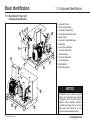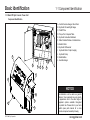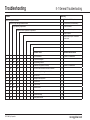
1
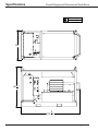
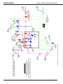
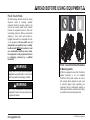
Spare Parts / Specifications Manual
DPU660-09 Diesel Hydraulic Power Unit
• Specifications
• Dimensional Drawings
• Schematics
• Assembly Drawings
DRILLING &
COMPLETIONS
mccoyglobal.com
mccoyglobal.com
Page 1
©2011 McCoy Corporation
AUTHORISED USE ONLY
Only authorised personnel who are deemed competent to operate,
maintain, and repair this equipment may do so.
© Copyright 2012 McCoy Corporation, including its wholly owned subsidiaries, (“McCoy”), all rights reserved. This document is the property of McCoy
and is supplied as reference information for users of our products. This document and the contents within are considered confidential information,
not to be disclosed, copied, transmitted, transcribed in any form, or stored on any type of data storage media without the express written consent of
McCoy.
McCoy has made every effort to ensure the information contained in this document is accurate and current. This manual is intended to provide equipment operation and safety instructions for your equipment. However, McCoy does not warrant or guarantee that the information is either complete or
accurate in every respect and the user of the manual should consult with its McCoy sales representative for any clarifications and updates.
The user of the manual shall protect, indemnify, and hold harmless McCoy and its directors, officers, employees, and agents from and against all liability for personal injury, death, or property damage resulting directly or indirectly from the use of the information contained in this manual.
Observance of all descriptions, information and instructions set out in this manual is the full responsibility of the user. This manual is intended for
guidance and informational purposes and must be used in association with adequate training and on-the-job supervision to provide safe and effective
equipment use.
It is the responsibility of the user to conform to all regulations and requirements issued by an authority or agency which may affect the operation, safety
or equipment integrity, that may overrule the content of this documentation.
The user will acknowledge and obey any general legal or other mandatory regulation in force relating to accident prevention, safety, and equipment
integrity.
©2011 McCoy Corporation
Page 2
mccoyglobal.com
WARNING
READ BEFORE USING EQUIPMENT
This Spare Parts / Specifications Manual is intended to be used as a companion
to the Operator’s Manual. DO NOT operate equipment without fully reviewing
and complying with all safety guidelines outlined in the separate Operator’s
Manual.
Please contact McCoy Drilling & Completions customer service to obtain the
appropriate Operator’s Manual if it has not been made available to you.
All components are suitable for their intended use and meet McCoy safety
requirements for normal use. Third party components present on this equipment
should be maintained as outlined in their respective Original Equipment
Manufacturer’s (OEM) documentation which is not covered in this manual.
McCoy Drilling & Completions | Superior
4225 Hwy 90 East • Broussard, LA USA
T: 1.337.837.8847
F: 1.337.837.8839
salesSuperior@mccoyglobal.com
mccoyglobal.com
Page 3
©2011 McCoy Corporation
©2011 McCoy Corporation
Page 4
mccoyglobal.com
Table of Contents
Specifications.............................. 7
Schematics................................ 11
Assembly Drawings................... 15
mccoyglobal.com
Page 5
©2011 McCoy Corporation
©2011 McCoy Corporation
Page 6
mccoyglobal.com
Specifications
Overall Equipment Dimensional Illustrations................................8
Specifications & Spare Parts........................................................9
mccoyglobal.com
Page 7
©2011 McCoy Corporation
Specifications
Overall Equipment Dimensional Illustrations
4,200 lbs (approx.)
1,905 kg (approx.)
50"
3
66 4 "
3
101 4 "
©2011 McCoy Corporation
Page 8
mccoyglobal.com
Specifications
Specifications & Spare Parts
Specifications
Diesel Motor Output
114 HP @ 2,300 RPM
Maximum Flow
60 GPM @ 1,000 PSI
Maximum Pressure
3,000 PSI
Hydraulic Oil Capacity
140 US GAL.
Diesel Tank Capacity
42 US GAL.
Operation Type
Open loop for over-center valve
Decibel Readings: 1.0 meter, 1 min 94 db (A), 97 db (C)
Spare Parts Recommendations
Qty
Part Number
Part Name
1
GNSH20-20
Dual Gear Pump 60GPM
2
P164697
Filter Elements
1
2.5 Strainer
Suction Strainer
1
1441
1” Male Quick Disconnect
1
1440
1” Female Quick Disconnect
1
1446
1 1/4” Male Quick Disconnect
1
1445
1 1/4” Female Quick Disconnect
mccoyglobal.com
Page 9
©2011 McCoy Corporation
©2011 McCoy Corporation
Page 10
mccoyglobal.com
Schematics
Power Unit Hydraulic Schematic..................................................12
mccoyglobal.com
Page 11
©2011 McCoy Corporation
©2011 McCoy Corporation
Page 12
14
13
LP
HP
14
HYD. OIL
RESERVOIR
4
3
7
FRONT
GAGE
Diesel
Engine*
DIESEL
RESERVOIR
HYDRAULIC SCHEMATIC
1
2
3.97 IN^3/REV EACH SECTION
30 GPM EACH SECTION AT 1800 RPM
3000 PSI MAX., 2500 RPM MAX.
SAE C MTG. SAE C SPLINED SHAFT (14T 12/24)
2 1/2" C61 INLET, 1" C61 OUTLET
#6 SAE O-RING GAGE PORTS AND UNLOAD PORT
PUMP SPECIFICATIONS
*DPU660-09 UTILIZES AN ELECTRIC START
DPU660-11 UTILIZES AN AIR START
11
1800 PSI
REAR
GAGE
8
6
12
HIGH
PSI
LOW
PSI
OFF / ON
5
RETURN
10
PRESSURE
9
mccoyglobal.com
LOG #
11/01/07
DATE
DPU660\Hyd Sch.wpg
REF: P:\Manuals\Equip Manuals\Dwgs\
REV. #
4225 HWY. 90 EAST
BROUSSARD, LA 70518
(318) 837-8847
3000 PSI
PU2500-H21
HEAT EXCHNAGER
F/ EX. PROOF
HIGH
PSI
OFF / ON
THIS DOCUMENT IS THE PROPERTY OF SUPERIOR MANUFACTURING &
HYDRAULICS AND IS CONSIDERED CONFIDENTIAL. THIS INFORMATION
MAY NOT BE USED, DISCLOSED, COPIED, OR REPRODUCED IN ANY
FORM, WITHOUT THE EXPRESS WRITTEN CONSENT OF SUPERIOR
MANUFACTURING & HYDRAULICS.
MANUAL
UNLOAD
PORT
LOW
PSI
15
Schematics
Power Unit Hydraulic Schematic
mccoyglobal.com
Page 13
1
1
1
1
1
1
1
3
2
7
8
9*
10 *
11
12
13
14
15
1508
1205
DT-45G
HRES-150
DPU660-S1
1445
1440
BAC-5M25RCFF
7040HL-011
BAC-3M25RCFF
2070
GNSH20-20
F6L914
1458
2.5 STRAINER
Part Number
Parte Número
1/2" Ball Valve, NPT, Low PSI
1/4" Stainless Ball Valve, High PSI
Diesel Tank 42 Gallon
Reservoir, 140 Gallons
Return Filter
1 1/4" Quick Disconnect – Female
1" Quick Disconnect – Female
Pressure Gauge, 0-5000
Throttle Cylinder Assembly
Pressure Gauge, 0-3000
System Relief Valve
Dual Gear Pump with Hi / Lo Valve 60 GPM
6 Cylinder Diesel Engine with Pump Drive
Suction Ball Valve, 2 1/2" NPT
Suction Strainer
English Description
Inglés Descripción
* FARR Specifications call for Male Quick Disconnects in place of Female
1
1
4
6
1
3
1
1
2
5
1
1
Item
Quantity
Artículo Cantidad
Spanish Description
Español Descripción
1/4" Inoxidable Bola Válvula, Alto PSI
1/2" Bola Válvula, NPT, Bajo PSI
Diesel Tanque 42 Galón
Depósito, 140 Galones
Vuelta Filtro
1 1/4" Aprisa Desconexión – Hembra
1" Aprisa Desconexión – Hembra
Presión Galga, 0-5000
Válvula Reguladora Cilindro Asamblea
Presión Galga, 0-3000
Sistema Relevación Válvula
Dual Engranaje Bomba con Alto / Bajo
Válvula 60 GPM
6 Cilindro Motor diesel con la impulsión de
la bomba
Succión Bola Válvula, 2 1/2" NPT
Succión Tamiz
HYDRAULIC SCHEMATIC
DIAGRAMA ESQUEMÁTICO HIDRÁULICO
BILL OF MATERIALS
CUENTA DE MATERIALES
Power Unit Hydraulic Schematic
Schematics
©2011 McCoy Corporation
©2011 McCoy Corporation
Page 14
mccoyglobal.com
Assembly Drawings
DPU660-09 Diesel Power Unit Assembly.....................................17
mccoyglobal.com
Page 15
©2011 McCoy Corporation
Assembly Drawings
©2011 McCoy Corporation
Page 16
mccoyglobal.com
Assembly Drawings
DPU660-09 Diesel Power Unit Assembly
Item
1
2
3
4
5
6
7
8
9
10
11
12
13
14
15
16
17
18
19
20
21
22
DPU660-05 DPU660-06
Part Number
Quantity Quantity
1
1
DSKD-02
1
1
DBSKT-02
1
1
HRES-150
1
1
GNSH20-20
1
1
1
1
1
1
1
1
1
1
1
1
1
3
2
0
0
1
1
1
1
1
1
1
1
1
1
1
1
1
1
3
2
1
1
1
DPU660-S1
1440
1445
1458
2070
F6L914
7042HL-013
DT-45G
2.5 STRAINER
7040HL-011
7042HL-015
BAC-3M25RCFF
BAC-5M25RCFF
1205
1508
HAK050017
DPU660-S2
KITFIT-DPU660
Description
SKID FOR 6 CYL. DIESEL POWER UNIT
HOSE BASKET FRAME FOR DIESEL POWER UNIT
HYDRAULIC RESERVOIR - 140 GALLONS
DOUBLE GEAR PUMP W/ HI/LOW VALVE
60 GPM / 60 GPM, 3000 PSI
RETURN FILTER
1" FEMALE QUICK DISCONNECT
1-1/4" FEMALE QUICK DISCONNECT
BALL VALVE, 2-1/2" L/P
1-1/4" NPT RELIEF VALVE (DUMP VALVE)
6 CYL. DIESEL ENGINE W/ PUMP DRIVE
GAUGE / BULKHEAD PANEL ASSEMBLY
DIESEL TANK - 42 GALLON
SUCTION STRAINER
THROTTLE CYLINDER ASSEMBLY
EMERGENCY STOP LABEL
GAUGE, 0-3000 PSI
GAUGE, 0-5000 PSI
1/2" BRASS BALL VALVE L.P.
1/4" SS H.P. VALVE
RETURN FILTER
KILL FROST LUBRICATOR
FITTING KIT F/6 CYL. POWER UNIT
NOT SHOWN IN THIS ILLUSTRATION
9
5
2
3
16
17
11
6
8
7
1
12
POWER UNIT WITHOUT
HOSE BASKET FRAME
3
5
10
4
APPROX. WEIGHT (LBS.) = 7,000
DIESEL POWER UNIT
mccoyglobal.com
DPU660-09 & -11
Sheet 1
4225 HWY. 90 EAST
BROUSSARD, LA 70518
(318) 837-8847
Page 17
©2011 McCoy Corporation
THIS DOCUMENT IS THE PROPERTY OF SUPERIOR MANUFACTURING &
HYDRAULICS AND IS CONSIDERED CONFIDENTIAL. THIS INFORMATION
MAY NOT BE USED, DISCLOSED, COPIED, OR REPRODUCED IN ANY
FORM, WITHOUT THE EXPRESS WRITTEN CONSENT OF SUPERIOR
MANUFACTURING & HYDRAULICS.
1
REV. #
LOG #
11/06/07
DATE
REF: P:\Manuals\Equip Manuals\Dwgs\
DPU660\DPU660-05 sh1 rev1.wpg
McCoy Drilling & Completions | Superior
4225 Hwy 90 East • Broussard, LA USA
T: 337.837.8847
F: 337.837.8839
salesSuperior@mccoyglobal.com
Operator’s Manual
Hydraulic Power Unit
• Commissioning
• Operation
• Maintenance
• Troubleshooting
• Decommissioning
DRILLING &
COMPLETIONS
READ BEFORE USING EQUIPMENT
Personnel
As a minimum, we recommend that all
personnel operating or working in the vicinity of
hydraulic equipment wear basic PPE (Personal
Protective Equipment) such as eye, ear, head,
hand, and foot protection. Only trained and
competent users should be allowed to directly
operate or operate around McCoy equipment.
Safety guidelines suggested by McCoy are
in no way intended to supersede the specific
health and safety regulations outlined by the
end user. Personnel safety guidelines and safe
workplace practices are the responsibility of the
end user.
Intent of Use
The hydraulic equipment provided should only
be used for the intended purposes as outlined
by McCoy. Any attempt to use equipment for
purposes other than its original intent exposes
personnel to potentially unforeseen hazards
and will void all warranties guaranteed by
McCoy.
Modification of Equipment
Any attempt by the user to apply unapproved
modifications to the equipment exposes
personnel to potential hazards and will void all
warranties guaranteed by McCoy. This includes
but is not limited to: bypassing or otherwise
disabling engineered safety features, use of
unapproved replacement parts, or jury-rigging
of any component or feature.
©2012 McCoy Corporation
Nature of Equipment
When attempting any operation with McCoy
equipment, the heavy duty nature of the
equipment and extreme forces generated when
the equipment components are put into motion
should always be taken into account in order to
maximize user safety and maintain equipment
longevity.
Rotary Components
Equipment doors should never be opened
when equipment components are under
load or rotating at a high rate of speed,
as this puts tremendous stress on internal
components and may lead to equipment failure.
Any damage incurred as a result is not covered
under any warranties.
Damaged or Faulty Components
Equipment with components that are operating
in a faulty manner or have otherwise been
significantly damaged must be immediately
removed from service until such a time that
it can be repaired or replaced by a qualified
technician. Continued use of faulty or damaged
equipment exposes personnel to significant
hazards and may compromise the longevity of
the equipment.
Local Regulations
user to be aware of any such regulations and
make preparations accordingly before placing
equipment into service.
Hydraulic Oil
Hydraulic oil used in McCoy equipment must be
filtered to a minimum of 10 microns. Hydraulic
oil contamination can be the cause of many
costly repairs. Please review the Hydraulic
Fluid Maintenance section before implementing
a hydraulic fluid maintenance routine.
Die Selection
Never attempt to clamp onto tubulars with
incorrectly sized dies. It is imperative that
operators be aware of the size of tubular to
be gripped and that the jaw and die system in
use is appropriately sized. Use of incorrectly
size dies poses a hazard to personnel and
may damage equipment. Please see your
equipment’s Spare Parts Manual for a list of
compatible jaws & dies.
Electrical Components
Extreme caution must be exercised when
connecting or disconnecting electrical cables
when in a potentially hazardous environment.
Electrical boxes which are pre-sealed from the
factory must never be opened due to the risk
of spark in potentially explosive atmospheres.
When placing equipment into service, local laws,
codes, and regulations must be considered and
adhered to. It is the responsibility of the end
mccoyglobal.com
READ BEFORE USING EQUIPMENT
Pinch / Touch Points
All OEM warning stickers should be closely
observed. Users of manually operated
equipment should be properly trained in its
use and be acutely aware of the potential
hazards the equipment poses to them and
surrounding personnel. McCoy recommends
adopting a ‘touch point’ paint scheme to
highlight areas which are acceptable to touch
on the equipment. All areas which are not
designated as an operation lever or a safety
handle should NEVER be touched or used
as a manipulation handle by users, unless
the equipment is fully de-pressurized and
is undergoing servicing by a qualified
technician.
Pinch / Touch Point Paint Schemes
& Warning Labels
WARNING
Placing limbs on or near areas of equipment
designated as a pinch point or a non ‘touch
point’ may result in serious injury or death.
WARNING
Use of any non-approved tong position
manipulation devices may expose personnel
to significant hazards.
mccoyglobal.com
● Manually operated tong operators should always stay within the recommended operator’s
position as illustrated above. Operator’s legs
are vertically clear of tong, hands only on operation lever or designated safety handle, and
body is clear of movement range of snubbing
line.
All McCoy equipment comes from the factory
painted according to our CE compliant
Pinch/Touch Point paint scheme, as well as
with warning labels designed to alert users
to potential danger. Upon repainting your
equipment, McCoy recommends adopting a
similar paint scheme to reduce the risk of injury
to operators and surrounding personnel.
©2012 McCoy Corporation
General
About This Manual
Hazard Notification
Maintenance & Service
This manual is intended to give users
general
guidelines
on
operating
and
working around McCoy equipment, as
well as to encourage good
maintenance
practices which will extend product life.
Throughout this manual, important notifications
and warnings appear intended to alert the user
of potential danger or practices which must
be observed. It is imperative that all notice or
warning boxes be observed.
By following the maintenance guidelines
outlined in this manual, the life of your
equipment can be drastically increased. The
information provided is intended to serve as a
basis for a robust maintenance program. It is
the responsibility of the end user to customize
and add to their own program based on
logistical and other concerns.
Illustrations contained within are provided as
a general reference and may not match the
appearance, configuration, or installed features
of your equipment. This manual is intended
as a companion to the model specific Spare
Parts & Specifications manual, which contains
assembly drawings, specifications, and
schematics relevant to your equipment. Please
contact our customer service department to
obtain a copy of either of these manuals.
©2012 McCoy Corporation
NOTICE
A notice box indicates a piece of information
which requires extra attention from the user.
WARNING
A warning box indicates information which, if
not properly observed, may expose users to
significant hazards that may result in severe
injury or death.
Should your equipment require servicing,
McCoy Drilling & Completions offers a full
hydraulic service shop to meet your needs.
Please contact McCoy Drilling & Completions
customer service department for more
information.
All equipment components are suitable for
their intended use and meet McCoy safety
requirements for normal use. Third party
components present on this equipment should
be maintained as outlined in their respective
Original Equipment Manufacturer’s (OEM)
documentation which is not covered in this
manual.
mccoyglobal.com
AUTHORISED USE ONLY
Only authorised personnel who are deemed competent to operate,
maintain, and repair this equipment may do so.
© Copyright 2012-2013 McCoy Corporation, including its wholly owned subsidiaries, (“McCoy”), all rights reserved. This document is the property of
McCoy and is supplied as reference information for users of our products. This document and the contents within are considered confidential information, not to be disclosed, copied, transmitted, transcribed in any form, or stored on any type of data storage media without the express written consent
of McCoy.
McCoy has made every effort to ensure the information contained in this document is accurate and current. This manual is intended to provide equipment operation and safety instructions for your equipment. However, McCoy does not warrant or guarantee that the information is either complete or
accurate in every respect and the user of the manual should consult with its McCoy sales representative for any clarifications and updates.
The user of the manual shall protect, indemnify, and hold harmless McCoy and its directors, officers, employees, and agents from and against all liability for personal injury, death, or property damage resulting directly or indirectly from the use of the information contained in this manual.
Observance of all descriptions, information and instructions set out in this manual is the full responsibility of the user. This manual is intended for
guidance and informational purposes and must be used in association with adequate training and on-the-job supervision to provide safe and effective
equipment use.
It is the responsibility of the user to conform to all regulations and requirements issued by an authority or agency which may affect the operation, safety
or equipment integrity, that may overrule the content of this documentation.
The user will acknowledge and obey any general legal or other mandatory regulation in force relating to accident prevention, safety, and equipment
integrity.
mccoyglobal.com
©2012 McCoy Corporation
Thank You.
We at McCoy would like to thank you for
entrusting our equipment to meet your Drilling
& Completions needs.
This manual is intended to give users
general
guidelines
on
operating
and
working around McCoy equipment, as
well as to encourage good
maintenance
practices which will extend product life.
Contacting McCoy
McCoy Drilling & Completions
4225 Hwy 90 East • Broussard, LA USA
T: 1.337.837.8847
F: 1.337.837.8839
dcsales@mccoyglobal.com
Illustrations contained within are provided as
a general reference and may not match the
appearance, configuration, or installed features
of your equipment. This manual is intended
as a companion to the model specific Spare
Parts & Specifications manual, which contains
assembly drawings, specifications, and
schematics relevant to your equipment. Please
contact our customer service department to
obtain a copy of either of these manuals.
©2012 McCoy Corporation
mccoyglobal.com
Table of Contents
Section 1
1-1 Component Identification
1-1.1 Basic Electric Power Unit
Component Identification
1-1.2 Basic Diesel Power Unit
Component Identification
1-1.3 Basic RP Style Console / Power Unit
Component Identification
1-1.4 Connection Panel Item Identification
Section 2
2-1 Status Monitoring
2-1.1 Operating Temperature
2-1.2 Operating Pressure
2-2 Commissioning
2-2.1 Making Up / Breaking Out Hydraulic
Connections
2-2.2 Moving and Placing the Unit
2-2.3 Ventilation Considerations
2-2.4 Initial Start-Up
2-2.5 Extreme Cold Weather Start-Up
Procedure
Section 3
3-1 Hydraulic Oil
3-1.1 Hydraulic Fluid Specifications
3-1.2 Hydraulic Fluid Maintenance
3-2 Fastener Torque
Specifications
3-2.1 Fastener Torque Specifications
Section 4
4-1 Maintenance
4-1.1 Maintenance Considerations
4-1.2 Daily Inspection & Maintenance
4-1.3 Decommissioning
4-1.4 Storage
4-1.5 Recommissioning
Section 5
5-1 General Troubleshooting
2-3 Operation
2-3.1 General Operation Notes
2-3.2 Depressurization Procedure
mccoyglobal.com
©2012 McCoy Corporation
©2012 McCoy Corporation
mccoyglobal.com
Basic Identification
Section 1
1-1 Component Identification
1-1.1 Basic Electric Power Unit
Component Identification
1-1.2 Basic Diesel Power Unit
Component Identification
1-1.3 Basic RP Style Console / Power Unit
Component Identification
1-1.4 Connection Panel Item Identification
mccoyglobal.com
©2012 McCoy Corporation
Basic Identification
1-1 Component Identification
1-1.1 Basic Electric Power Unit
Component Identification
G
H
I
A
B
F
J
C
D
E
K
M
N
©2012 McCoy Corporation
L
A. Hydraulic Oil Filter
B. Power Connection Box
C. Hydraulic Pump Assembly
D. Hydraulic Reservoir Drain Valve
E. Electric Motor
F. Hydraulic Oil Level Sight Gauge
G. Starter Box
H. Low Oil Level Shutdown
I. Hydraulic Oil Filler Cap
J. Heat Exchanger
K. Hydraulic Oil Reservoir
L. Connection Panel
M. Skid Weldment
N. High Pressure Filter
NOTICE
This illustration is to be used as a general
reference. Your equipment may vary greatly
in appearance due to the wide range of
equipment options available throughout
our product line. Please refer to your tool’s
specific spare parts manual for a more
accurate component assembly drawing.
mccoyglobal.com
Basic Identification
1-1 Component Identification
1-1.2 Basic Diesel Power Unit
Component Identification
D
E
F
G
A
B
C
H
mccoyglobal.com
I
J
K
N
L
M
A. Hydraulic Oil Filler Cap
B. Sight Glass
C. Hydraulic Oil Reservoir
D. Dump Valve
E. Hydraulic Return Filter
F. Hose Basket
G. Lifting Eye
H. Hydraulic Oil Reservoir Drain Valve
I. Hydraulic Pump
J. Diesel Tank
K. Heat Exchanger
L. Forklift Lifting Tube
M. Diesel Tank Filler Cap
N. Diesel Engine
NOTICE
This illustration is to be used as a general
reference. Your equipment may vary greatly
in appearance due to the wide range of
equipment options available throughout
our product line. Please refer to your tool’s
specific spare parts manual for a more
accurate component assembly drawing.
©2012 McCoy Corporation
Basic Identification
1-1 Component Identification
1-1.3 Basic RP Style Console / Power Unit
Component Identification
A. Control Console Gauge / Valve Panel
B. Hydraulic Oil Level Sight Gauge
C. Forklift Tube
D. Torque Turn Computer Table
E. Hydraulic Connection Bulkhead
F. Motor Rotation Window / Indicator Arrow
G. Electric Motor
H. Hydraulic Oil Reservoir
I. Hydraulic Motor / Pump Coupling
J. Hydraulic Pump
K. Electrical Box
L. Heat Exchanger
A
G
H
I
J
K
D
B
NOTICE
E
C
F
L
©2012 McCoy Corporation
This illustration is to be used as a general
reference. Your equipment may vary greatly
in appearance due to the wide range of
equipment options available throughout
our product line. Please refer to your tool’s
specific spare parts manual for a more
accurate component assembly drawing.
mccoyglobal.com
1-1 Component Identification
Basic Identification
1-1.4 Connection Panel Item
Identification
●●Load Sense: Connection point to connect
the load sense feature of the power unit’s
hydraulic pump.
oil psi
oil temp
low psi
high psi
1500
1000
500
100
150
150
50
1000
2500
200
100
250
200
bar
psi
3000
on
off
●●Air: Connection point for compressed air
4000
300
50
bar
psi
●●Remote Start: Connection point for remote
start
3000
2000
2000
●●Case Drain: Connection point for the case
drain
350
5000
●●E.S.D Pull: Emergency Shut Down pull lever
to be used in emergency situations only.
on
off
●●Oil PSI: Gauge which displays current engine
oil pressure
●●Oil Temp: Gauge which displays current
engine oil temperature
pressure
e.s.d.
pull
return
air
●●0 - 5000 System Pressure: Gauge showing
current hydraulic system pressure
●●Return: Port to connect the hydraulic return
line.
●●Low PSI: 0-3000 pressure gauge displaying
current system pressure
●●High PSI: 0-5000 pressure gauge displaying
current system pressure
●●Pressure: Port to connect the hydraulic
pressure line.
●●Change Filters Indicator Light: When lit,
indicates that it is time to replace the hydraulic
filter elements.
mccoyglobal.com
©2012 McCoy Corporation
©2012 McCoy Corporation
mccoyglobal.com
Commissioning & Operation
Section 2
2-1 Status Monitoring
2-1.1 Operating Temperature
2-1.2 Operating Pressure
2-2 Commissioning
2-2.1 Making Up / Breaking Out Hydraulic
Connections
2-2.2 Moving and Placing the Unit
2-2.3 Ventilation Considerations
2-2.4 Initial Start-Up
2-2.5 Extreme Cold Weather Start-Up
Procedure
2-3 Operation
2-3.1 General Operation Notes
2-3.2 Depressurization Procedure
mccoyglobal.com
©2012 McCoy Corporation
Commissioning & Operation
2-1.1 Operating Temperature
2-1 Status Monitoring
2-1.2 Operating Pressure
1500
1000
77
500
150
50
bar
psi
●● ISO68 hydraulic oil is designed to operate at
a temperature range of 130 degrees F (55 degrees C) to 170 degrees F (77 degrees C), in
order to maintain proper viscosity of 100 SSU.
The use of an oil cooler may be required if the
operating temperature reaches the maximum
temperature.
●●This equipment is designed to operate at a
maximum acceptable working temperature
of 190° (87° C) measured at external bearing
caps or other similar surfaces.
WARNING
Equipment and hydraulic hoses reach temperatures during normal operation that can
cause severe burns. Appropriate hand protection should be worn at all times to avoid
injury.
©2012 McCoy Corporation
2000
100
2500
200
3000
●●Most hydraulic components are designed with
a maximum working pressure of 3,000 PSI
(207 bar).
●●Certain components, such as hydraulic cylinders used as remotely controlled actuators,
have working pressure limits of 1500 PSI (103
bar).
WARNING
Hydraulic reducing valves are used to limit
pressure to certain components and must
never be adjusted. Adjusting these valves
beyond factory settings can result in equipment failure, hydraulic leaks, and can expose
personnel to hazards that can result in serious injury or death.
mccoyglobal.com
2-2 Commissioning
Commissioning & Operation
2-2.1 Making Up / Breaking Out
Hydraulic Connections
●●Before connecting any hydraulic joint, always
inspect hoses for damage and any dirt or
contaminants. Clean as necessary with compressed air or an approved cleaning solvent
in combination with a lint-free cloth.
mccoyglobal.com
Fully make up connection to
●●Wing type hydraulic disconnects should almarked point on male fitting
ways be fully made up to the connection line
on the joint. Prior to pressurizing the hydraulic
system, all hydraulic connections should be
inspected to ensure a secure connection has
been established.
●●Attached to each hydraulic outlet is a brass
(or plastic) dust cap. Whenever a hose is disconnected, dust caps should always be reattached to prevent contaminants from entering
the hydraulic system.
●●Before attempting to break out hydraulic connections, assure that the tong has be depressurized and is fully disconnected from any hydraulic power sources. Hydraulic return lines
should always be made up first and broken
out last in order to insure that pressure is not
trapped in the valve package.
©2012 McCoy Corporation
Commissioning & Operation
2-2 Commissioning
2-2.2 Moving and Placing the Unit
●●For additional information regarding proper
rigging and overhead lifting , refer to OSHA,
ASME B30.9-2006. For additional information
on load bearing devices, see OSHA 1910.184,
ANSI/ASME B30.9 ”SLINGS”, ANSI/ASME
B30.10 ”HOOKS” and ANSI/ASME B30.26
“RIGGING HARDWARE”.
(side view)
●●Lifting of the power unit should always be
performed by using either the pad eye lifting
mounts located at the top of the frame or the
forklift lifting slots located at the base of the
frame.
●●When lifting with cables attached to the padeye lifting mounts, lifting should only be performed with all four (4) points bearing the load
evenly in a stable, level manner. Any sling or
lifting device and associated rigging equipment should be, at minimum, rated to lift the
total weight of the power unit multiplied by a
factor of two (2). Refer to unit’s specifications
manual for approximate weights.
●●All load bearing devices provided are tested
to 1.5x - 2x their reported carry weight and are
issued certification tags. It is the responsibility
of the end user to re-certify these devices at
regular intervals (maximum 9 months as per
AUWED 95/63/Ec (LOLER) in the EEA) to assure maximum safety.
WARNING
Any load bearing device that is observed to
have visible damage or is otherwise compromised must be immediately removed from
service until it can be repaired or replaced.
36”
(0.9m)
(top view)
●●The power unit should only be set down on
a level surface with adequate clearance (3ft
recommended) on all sides of the unit to allow for maintenance and service. Surfaces
should provide adequate vibration and deflection prevention, as well as providing a sufficient load rating to support the full weight of
the power unit.
●●Distance from equipment to be powered
should be factored in, and all hydraulic hoses
and miscellaneous cables should be of sufficient length as to not place undue stress on
outlets.
●●Avoid placing the power unit directly on surfaces that are constantly wet as to prevent
added potential for unit frame corrosion.
©2012 McCoy Corporation
mccoyglobal.com
2-2 Commissioning
Commissioning & Operation
2-2.3 Ventilation Considerations
●● When operating diesel power units in an enclosed environment, assure that the unit is
placed in an area with sufficient ventilation to
assure that exhaust fumes do not accumulate.
WARNING
If the power unit is to be placed within an
enclosed area, it is imperative that sufficient
ventilation be maintained. Local mechanical
codes should be consulted when considering
indoor placement locations and setups. Poor
ventilation may result in the accumulation of
exhaust fumes or heat which poses a health
risk to personnel. See power unit engine
manual for more information.
mccoyglobal.com
©2012 McCoy Corporation
Commissioning & Operation
2-2.4 Initial Start-Up
1. Remove any shipping restraints that may be
present on the equipment
2. Ensure adequate lubrication, oil, and fuel
(if applicable) levels.
●● Fill hydraulic reservoir with specified
hydraulic oil. Ensure suction isolation
valve is open.
●● Fill chain drive case with specified gear oil.
●● Lubricate all grease fittings with specified
bearing grease.
●● See any third party component’s operator’s
manual for manufacturer specific start up
instructions.
3. Attach supply and return hydraulic hoses
from corresponding equipment to power
unit.
4. (if applicable) Connect air supply line.
5. (if applicable) Position both High and
Low PSI switches to the OFF position (if
applicable).
6. Assure any shut down valves are set to the
RUN position.
7. Start up power unit.
●● Assure that the direction of rotating
©2012 McCoy Corporation
2-2 Commissioning
2-2.5 Extreme Cold Weather
Start-Up Procedure
components
on
the
unit
match
corresponding rotational direction stickers.
Immediately shut down unit if incorrect
rotation direction is observed.
●● If upon start up abnormally high engine
RPM are observed, power down the system and assure that all hydraulic connections are fully made up and properly
secured. High RPM is a symptom of restriction in the supply or return lines may
cause motor seal failure.
●●Consult the power unit engine manufacturer’s
operator’s manual for all cold weather operating procedures and precautions.
●●Select hydraulic fluid and gear & bearing lubricants that are compatible with expected
climate conditions.
●●If the power unit is equipped with an oil
temperature gauge, ensure that the oil has
reached an acceptable operating temperature
specified by the hydraulic fluid data sheet.
8. Push air shut valve (if applicable) and allow
power unit engine to idle for 5-10 minutes
until warm.
9. (if applicable) Position High and Low PSI
switches to the ON position.
●●Before releasing the equipment to an operational environment, it is recommended that
the following tests be performed to assure
that equipment damage has not occurred during shipping.
10.Connect the power unit to corresponding
equipment and operate the equipment for
a duration of one half hour through normal
operating parameters.
11.After operation, visually inspect the
equipment and hydraulic fittings for obvious
malfunction.
WARNING
As a minimum, we recommend that all
personnel operating or working in the vicinity
of hydraulic equipment wear basic PPE
(Personal Protective Equipment) such as
eye, ear, head, hand, and foot protection.
Only trained and mentally competent users
should be allowed to directly operate or
operate around McCoy equipment.
mccoyglobal.com
2-3 Operation
Commissioning & Operation
2-3.1 General Operation Notes
●●When shutting down the unit under normal
operation, always use the nominal shut down
method (either by means of a starter box or
engine pull level) and not the ESD (Emergency
Shut Down) switch. ESD switches should only
be used in emergency situations as daily use
may damage engine components.
●●If any abnormal noise or odor is detected
during operation, immediately shut down
the equipment and perform an inspection to
prevent potential damage.
2-3.2 Depressurization Procedure
WARNING
Hydraulic equipment can utilize up to 3,000
psi of high pressure hydraulic fluid. Portions
of the tool, including control valves, hydraulic lines, and cylinders may contain high
pressure fluid even when the power unit is
de-energized and the fluid supply hoses are
disconnected. During normal operation the
temperature of the hydraulic fluids as well as
hoses, piping, valves, etc., can rise to a level
which can cause burns. Always wear protective gloves when handling hydraulic lines.
●●Before
disconnecting
any
hydraulic
connection, the following procedure must
first be completed to ensure the safety of all
personnel and to avoid possible damage to
hydraulic components.
1. Ensure that the equipment to be
depressurized is located in an area with
sufficient drainage to handle any expelled
hydraulic oil.
2. Consult
corresponding
equipment’s
operation
manual
for
proper
depressurization procedure to coincide with
power unit depressurization.
3. De-energize the hydraulic power supply.
4. Remove the hydraulic supply hose from the
equipment.
5. Remove the hydraulic return hose.
mccoyglobal.com
©2012 McCoy Corporation
©2012 McCoy Corporation
mccoyglobal.com
Fluids, Lubrication, & Torque
Section 3
3-1 Hydraulic Oil
3-1.1 Hydraulic Fluid Specifications
3-1.2 Hydraulic Fluid Maintenance
3-2 Fastener
GeartrainTorque
GreaseSpecifications
3-2.1 Fastener
GeartrainTorque
GreaseSpecifications
Specifications
3-3 Bearing Grease
3-3.1 Bearing Grease Specifications
3-4 Fastener Torque Specifications
3-4.1 Fastener Torque Specifications
mccoyglobal.com
©2012 McCoy Corporation
Fluids, Lubrication, & Torque
3-1.1 Hydraulic Fluid
Specifications
When replacing hydraulic fluid, always use
a fluid that meets or exceeds the standards
displayed in the table provided. Use of unapproved hydraulic fluid may lead to equipment
damage.
Use the following standards when selecting
hydraulic fluid for use in CLINCHER® brand
equipment.
NOTICE
It is imperative that ONLY hydraulic fluid that
meets the standards listed on this page be
used in your hydraulic equipment. Use of
unapproved hydraulic fluid, including fire resistant fluids, water based fluids, and high
viscosity fluids, or fluids that do not meet the
specified standards, may result in extensive
equipment damage which is not covered under any warranties.
3-1 Hydraulic Oil
Hydraulic Fluid Standards
Specification
Value
ISO Viscosity Grade1
68
Base Oil Viscosity:
ASTM D 445
cSt @ 40° C
cSt @ 100° C
65.0
8.5
Viscosity Index – ASTM D 2270
95
Pour Point – ASTM D 97
-9
Flash Point – ASTM D 92
C(°F)
222 (432)
Demulsibility – ASTM D 1401
41/39/0 (20)
Vickers 104C (IP281) (or equivalent)
Pass
Vickers M-2950-S (or equivalent)
Quality Level
Vickers I-286-S (or equivalent)
Quality Level
TOST – ASTM D 943
2000+
1
NOTE: ISO 46 grade hydraulic oil may be used in place of ISO 68 oil when utilizing power units equipped with both a hydraulic
oil cooler and heater.
NOTICE
ALL new fluid that is to be introduced into the
system must be cleaned and filtered before
being pumped into the hydraulic reservoir.
©2012 McCoy Corporation
mccoyglobal.com
3-1 Hydraulic Oil
Fluids, Lubrication, & Torque
3-1.2 Hydraulic Fluid Maintenance
When implementing hydraulic equipment into
a schedule of regular service, it is essential
to adopt a regimented, properly administrated
hydraulic fluid maintenance schedule. Many
costly hydraulic system repairs can be drastically reduced or completely eliminated this way.
Benefits of implementing a regular, properly administered hydraulic fluid maintenance program
include:
● Increased system reliability and performance
● Eliminates repair costs due to hydraulic oil
contamination
● Saves time and money by keeping equipment
in the field rather than the service shop
Fluid Contamination
Hydraulic fluid becomes contaminated when
foreign matter is introduced into the hydraulic
system, which then leads to internal wear and
eventual component damage. Contaminants
can be introduced into the hydraulic system in
two ways:
Internally Generated Contamination
Failing internal components in a hydraulic system can cause fluid contamination levels to rise
to unacceptable levels. This type of contamination will appear as wear debris.
mccoyglobal.com
Externally Generated Contamination
External contaminants can be introduced to hydraulic fluid through hydraulic connections, cylinder rods, or improperly sealed hydraulic fluid
reservoirs. Keeping exposed cylinder rods and
hydraulic quick disconnects free from debris is
essential in preventing this type of contamination.
Recommended Testing Standards
Hydraulic fluid testing can be conducted with
the use of a portable fluid condition testing kit,
or by lab analysis. When setting up a hydraulic
fluid maintenance schedule, we recommend a
combination of both of these mediums to assure accuracy in testing. While convenient, portable fluid condition test kits are not as accurate
or thorough as lab testing.
Testing should be conducted at regular intervals and any time a hydraulic overhaul or
major maintenance is performed on the equipment. Test samples should be taken from the
return line (upstream of the return filter) when
the system is at regular operating temperature.
Designating time between testing may vary depending on working environment and end user
maintenance policies.
Recommended Filtering Standards
All hydraulic fluid intended for use in McCoy
equipment should be filtered to a minimum of
5-10 microns. All new fluid that is to be introduced into the system must be cleaned
and filtered before being pumped into the
hydraulic reservoir.
Filters should be changed regularly. Assuming
cleanliness levels are within normal parameters, it is recommended that spin-on type filters be changed after fifty (50) hours of initial
use and then after every two hundred fifty (250)
hours of use. Use of a filter condition indicator
is recommended.
Flushing the Hydraulic System
If testing shows the system’s hydraulic fluid
is outside of acceptable cleanliness margins,
the hydraulic system should be flushed with
the use of a filter cart. Once the fluid has been
flushed and has returned to optimal cleanliness
levels, all filters in the hydraulic system should
be changed out. Flushing should also be performed before putting any new equipment into
service or after performing system maintenance
or overhauling existing equipment.
PLEASE NOTE:
This basic outline is intended to raise the
awareness of hydraulic system maintenance of
the end user, but is in no way intended to be a
complete reference for the implementation of a
hydraulic system maintenance program.
©2012 McCoy Corporation
Fluids, Lubrication, & Torque
3-4.1
Torque
3-2.1 Fastener
Fastener Torque
Specifi
cations
Specifications
Most fasteners and threaded components listed
should be coated with Never-Seez® or equivalent prior to assembly. Certain fasteners or
components require the application of Loctite®
before installation. It is important to first reference the corresponding assembly drawing to
obtain such information.
All tapered pipe thread connections be sealed
and locked using Loctite 569™ hydraulic sealant. Use of Loctite cleaning solvents activators
7471™ or 7649™ should be used on inactive
metals and to speed curing process.
WARNING
Use of inferior fasteners or failing to meet the
torques specified on this page may lead to
equipment malfunction that exposes nearby
personnel to significant hazards.
NOTICE
Replacement fasteners are to be GRADE 8
or better.
NOTICE
The use of Teflon tape or Teflon based thread
sealing compounds on hydraulic system
connections is not advised, as they can
cause system contamination.
©2012 McCoy Corporation
3-4 Fastener Torque Specifications
3-2
Specifications
Fastener Torque Specifications
Fastener Size (in)
Typical Installation
Required Torque (ft-lbs)
1/4 - 20 NC
Tong door switch assembly bolts, tong door guard support
strip, tong jaw clip bolts
14
1/4 - 20 Set Screws
Encoder coupling2, jaw spring clip2
N/A
3/8 - 16 Set Screws
Bearing caps1, door switch adjustment sleeve4
N/A
3/8 - 16 NC
Housing cover, brake bands, backup side plates, tong &
backup clip bolts
38
1/2 - 13 NC
Top secondary bearing cap, cage plate bolts, locking pin,
ring gear key, motor mounts, backup halo, leg bolts
93
5/8 - 11 NC
Tong plates, bearing caps, idler shaft bolts, cam follower
nuts, backup cylinder gland bolts, hanger bolts
180
5/8 - 18 NF
Cam follower
55
3/4 - 10 NC
Cage plate spacer bolts, jaw adapter bolts, backup bolts,
rigid bail bolts
317
7/8 - 14 NF
Cam follower
512
1 - 8 NC
UHT backup backing bolt
100
1 - 12 NF
Dumbell roller3, tong door jam nut
N/A
1 - 14 NC
Idler shaft
100
1 1/4 - 12 NF
Backup bulkhead connector
100
1 1/2 - 12 NF
Idler shaft
1200
1
Coat with removable Loctite®. Tighten until screw contacts bearing, then back off (1) turn.
2
Tighten until snug.
3
Tighten until all slack is removed but dumbell roller is free to rotate by hand.
4
Coat with removable Loctite®. Tighten until snug.
mccoyglobal.com
mccoyglobal.com
©2012 McCoy Corporation
©2012 McCoy Corporation
mccoyglobal.com
Inspection & Maintenance
Section 4
4-1 Maintenance
4-1.1 Maintenance Considerations
4-1.2 Daily Inspection & Maintenance
4-1.3 Decommissioning
4-1.4 Storage
4-1.5 Recommissioning
mccoyglobal.com
©2012 McCoy Corporation
Inspection & Maintenance
4-1.1 Maintenance Considerations
NOTICE
When carrying out these maintenance
procedures, hydraulic fluid and industrial
lubricants will be expelled or rinsed off of the
equipment. Ensure adequate containment
is in place to prevent environmental
contamination.
Equipment systems utilizing exterior electrical
components must be hand washed. Never
directly spray electrical cables or equipment
with a high pressure wash.
All third party components (engine, pump,
heat exchanger, etc.) that may be present
must be maintained according to the original
equipment manufacturer’s guidelines which
are not detailed in this manual.
WARNING
No maintenance work is to be carried out
while the equipment is connected to a hydraulic power supply.
4-1 Maintenance
4-1.2 Daily Inspection
& Maintenance
4-1.3 Decommissioning
1. Wash unit to remove majority of dirt and
grease build up to allow for inspection of the
overall condition of unit.
●●The following procedure is to be carried out
to prepare equipment for short or long term
storage. It is imperative that these instructions
be strictly observed to ensure maximum
longevity.
2. Inspect for major damage or excessive
wear.
3. Inspect all hoses for wear. Replace as
necessary.
4. Refer to engine manufacturer’s for required
engine maintenance procedure.
5. Follow power unit start up procedure. Test
unit under normal work load. Re-inspect
all hoses and hydraulic system for leaks.
Repair or replace if necessary.
6. Check condition indicator on return filter
elements. Replace as necessary or at 6
month intervals.
7. Test hydraulic oil for contamination every 6
months under normal operation conditions.
Replace with new filtered oil as required.
8. Refer
to
third
party
component
manufacturer’s maintenance literature and
carry out as instructed.
1. Depressurize the equipment.
2. Disconnect any remaining hoses or lines.
3. Completely drain fluid reservoirs.
4. Wash the exterior of the equipment to
remove the majority of dirt and grease
buildup.
5. Wash the interior of the equipment
thoroughly, using either water (do not use
a pressure washer), or an appropriate
solvent-based grease cutting cleaner such
as Varsol®. If metal shavings or chips
are observed being flushed out of the
equipment, an overhaul of the equipment
must be performed to eliminate the issue
and prevent further damage.
6. Thoroughly wash the exterior of the
equipment using either water (do not use
a pressure washer) or an appropriate
solvent-based grease cutting cleaner such
as Varsol®.
7. Inspect all paint. Locations in which the
paint has been damaged must be repaired
©2012 McCoy Corporation
mccoyglobal.com
4-1 Maintenance
Inspection & Maintenance
4-1.4 Storage
prior to storage. Prepare areas to be painted
to ensure they are free of grease, dirt, or
solvent. Touch up with appropriate paint.
Allow sufficient time for paint to dry before
proceeding.
8. Perform a complete lubrication of all externally accessible grease fittings on equipment.
9. Connect a low-pressure air supply line (10
PSI or less) to the hydraulic supply line,
and force a small amount of the remaining
hydraulic fluid from the valve assembly.
This will allow for thermal expansion of the
hydraulic fluid if the equipment is stored or
transported in high ambient temperatures.
Failure to do this may result in damaged or
destroyed seals in the equipment.
application and safety information.
12.Allow the anti-corrosive coating ample time
to dry. Refer to manufacturer data sheets for
drying times at room temperature.
13.Wrap entire assembly in 100 gauge (1 mil)
corrosion-inhibiting wrap, at least 3 layers
thick. Ensure that the tool is well sealed
within the wrapping, including the bottom.
●●For optimum longevity, it is recommended
that equipment be stored in a sealed,
climate controlled environment. McCoy
recommends using a silica gel desiccant to
reduce the humidity within the wrapping. 125
g of desiccant should be used for each cubic
meter of space (3.5 g per cubic foot).
10.Wipe all excess grease from outside of
equipment. Use a solvent-based cleaner on
rags to wipe all external surfaces to remove
residual grease or hydraulic fluid. Once the
outside surfaces have been de-greased,
wipe all external surfaces with clean water
to remove residual solvent.
11.McCoy recommends that an anti-corrosive
agent such as Tectyl® 506 be applied
to all external surfaces (including chain
slings) EXCEPT cylinder rods. Refer
to manufacturer data sheets for proper
mccoyglobal.com
©2012 McCoy Corporation
Inspection & Maintenance
4-1 Maintenance
4-1.5 Recommissioning
●●The following procedure is to be carried out
when removing equipment from storage and
into a working environment. This procedure
assumes that the equipment in question has
been decommissioned in accordance with the
steps listed in this manual.
1. Remove all protective plastic wrapping.
Dispose of any desiccant packs.
2. Wipe excess grease or heavy oil from
exposed cylinder rods (if applicable).
3. If applicable, re-connect chain sling to lifting
lugs. Perform a visual inspection of all lifting
points. if visible damage is seen, including
cracks, broken lugs, distorted metal, etc.,
replace damaged part(s) before placing
equipment in service. If your company
requires yearly certification of lifting
equipment, ensure that the most recent
test date falls within the past year. Perform
recertification if necessary.
7. Assure pressure and temperature are
nominal.
8. Perform a thorough inspection of
pressurized hydraulic lines and fittings.
Any leaking hydraulic fluid lines or fittings
must be replaced before the equipment is
returned to service.
9. Perform a thorough inspection of all seals.
Any seal that is leaking or “weeping”
must be replaced before the equipment is
returned to service.
10.Run power unit under normal work load to
ensure proper functionality.
11.When all of the previous steps are
completed, you may return your recommissioned equipment to service.
4. Perform a complete lubrication of all
externally accessible grease fittings on
equipment.
5. Fill fluid reservoirs to appropriate levels
using specified fluids.
6. Perform the start up procedure to energize
the power unit.
©2012 McCoy Corporation
mccoyglobal.com
mccoyglobal.com
©2012 McCoy Corporation
©2012 McCoy Corporation
mccoyglobal.com
Troubleshooting
Section 5
5-1 General Troubleshooting
mccoyglobal.com
©2012 McCoy Corporation
Troubleshooting
5-1 General Troubleshooting
Problem
Action Key
Insufficient System Pressure
F
Flush hydraulic fluid & replace
CH
Check fluid levels, add as necessary
CL
Clean / clear debris
L
Inspect for fluid leaks, repair as necessary
R
Repair or replace
IN
Inspect, realign / adjust / re-calibrate to
correct value
LU
Lubricate components
Hydraulic Pump Making Excessive Noise
High Operating Temperature
Excessive Wear to Hydraulic Components
•
•
•
•
•
•
•
•
•
•
•
•
•
•
•
•
•
•
•
•
•
©2012 McCoy Corporation
Possible Cause
•
•
•
•
•
•
Relevant Manual Section
Fluid contamination
F
Components misaligned
IN
High operating pressures
IN
Exhausted fluid (depletion of additives)
F
Air in fluid / fluid suction above fluid level in reservoir
L / CH
Restricted supply line / clogged reservoir intake
CL / L
Low fluid level
CH / L
Damaged or worn equipment
R
Restricted vent
IN / R
Excessive RPM
IN / R
Increased friction
IN / R
Damaged relief valve or check valve
R
Restricted discharge
CL / IN
Valve system restricted
CL / L
Hydraulic Fluid Maintenance
Hydraulic Fluid Maintenance
mccoyglobal.com
mccoyglobal.com
©2012 McCoy Corporation
McCoy Drilling & Completions
4225 Hwy 90 East • Broussard, LA USA
T: 337.837.8847
F: 337.837.8839
dcsales@mccoyglobal.com
©2012 McCoy Corporation
mccoyglobal.com