1
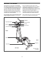
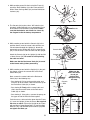
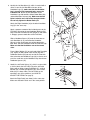
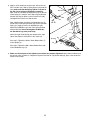
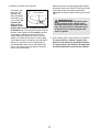
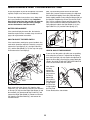
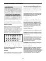
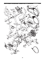
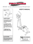
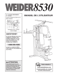
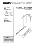
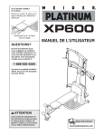
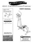
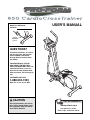
Model No. PFEL29222
Serial No.
USER’S MANUAL
Serial
Number
Decal
QUESTIONS?
If you have questions, or if there
are missing parts, we will guarantee complete satisfaction
through direct assistance from
our factory.
TO AVOID DELAYS, PLEASE
CALL DIRECT TO OUR TOLLFREE CUSTOMER HOT LINE. The
trained technicians on our customer hot line will provide immediate assistance, free of charge to
you.
CUSTOMER HOT LINE:
1-888-533-1333
Mon.–Fri., 6 a.m.–6 p.m. MST
CAUTION
Read all precautions and instructions in this manual before using
this equipment. Keep this manual for future reference.
Visit our website at
www.proform.com
new products, prizes,
fitness tips, and much more!
TABLE OF CONTENTS
IMPORTANT PRECAUTIONS . . . . . . . . . . . . . . . . . . . . . . . . . . . . . . . . . . . . . . . . . . . . . . . . . . . . . . . . . . . . . . . .3
BEFORE YOU BEGIN . . . . . . . . . . . . . . . . . . . . . . . . . . . . . . . . . . . . . . . . . . . . . . . . . . . . . . . . . . . . . . . . . . . . . .4
ASSEMBLY . . . . . . . . . . . . . . . . . . . . . . . . . . . . . . . . . . . . . . . . . . . . . . . . . . . . . . . . . . . . . . . . . . . . . . . . . . . . . . .5
HOW TO USE THE ELLIPTICAL CROSSTRAINER . . . . . . . . . . . . . . . . . . . . . . . . . . . . . . . . . . . . . . . . . . . . . . .9
MAINTENANCE AND TROUBLESHOOTING . . . . . . . . . . . . . . . . . . . . . . . . . . . . . . . . . . . . . . . . . . . . . . . . . . .12
CONDITIONING GUIDELINES . . . . . . . . . . . . . . . . . . . . . . . . . . . . . . . . . . . . . . . . . . . . . . . . . . . . . . . . . . . . . . .13
PART LIST . . . . . . . . . . . . . . . . . . . . . . . . . . . . . . . . . . . . . . . . . . . . . . . . . . . . . . . . . . . . . . . . . . . . . . . . . . . . . .14
EXPLODED DRAWING . . . . . . . . . . . . . . . . . . . . . . . . . . . . . . . . . . . . . . . . . . . . . . . . . . . . . . . . . . . . . . . . . . . .15
HOW TO ORDER REPLACEMENT PARTS . . . . . . . . . . . . . . . . . . . . . . . . . . . . . . . . . . . . . . . . . . . . .Back Cover
LIMITED WARRANTY . . . . . . . . . . . . . . . . . . . . . . . . . . . . . . . . . . . . . . . . . . . . . . . . . . . . . . . . . . . . . .Back Cover
PROFORM is a registered trademark of ICON IP, Inc.
2
IMPORTANT PRECAUTIONS
WARNING:
To reduce the risk of serious injury, read the following important precautions before using the elliptical crosstrainer.
1. Read all instructions in this manual before
using the elliptical crosstrainer.
8. Always hold the console handgrip or the handlebars when mounting, dismounting, or
using the elliptical crosstrainer.
2. It is the responsibility of the owner to ensure
that all users of the elliptical crosstrainer
are adequately informed of all precautions.
9. The pulse sensor is not a medical device.
Various factors may affect the accuracy of
heart rate readings. The pulse sensor is
intended only as an exercise aid in determining heart rate trends in general.
3. Place the elliptical crosstrainer on a level
surface, with a mat beneath it to protect the
floor or carpet. Keep the elliptical crosstrainer indoors, away from moisture and dust.
10. Keep your back straight when using the elliptical crosstrainer; do not arch your back.
4. Inspect and properly tighten all parts regularly. Replace any worn parts immediately.
11. If you feel pain or dizziness at any time
while exercising, stop immediately and
begin cooling down.
5. Keep children under 12 and pets away from
the elliptical crosstrainer at all times.
12. When you stop exercising, allow the pedals
to slowly come to a stop.
6. The elliptical crosstrainer should not be used
by persons weighing more than 250 pounds.
13. The elliptical crosstrainer is intended for
home use only. Do not use the elliptical
crosstrainer in a commercial, rental, or institutional setting.
7. Wear appropriate exercise clothing when
using the elliptical crosstrainer. Always wear
athletic shoes for foot protection.
WARNING:
Before beginning this or any exercise program, consult your physician.
This is especially important for persons over the age of 35 or persons with pre-existing health problems. Read all instructions before using. ICON assumes no responsibility for personal injury or
property damage sustained by or through the use of this product.
3
BEFORE YOU BEGIN
Congratulations for selecting the new PROFORM®
650 CARDIO CROSSTRAINER. The PROFORM 650
is an incredibly smooth exerciser that moves your feet
in a natural elliptical path, minimizing the impact on
your knees and ankles. And the unique PROFORM
650 features adjustable resistance and a simple-touse console to help you get the most from your exercise. Welcome to a whole new world of natural, elliptical-motion exercise from PROFORM.
tions after reading this manual, please call our
Customer Service Department toll-free at 1-888-5331333, Monday through Friday, 6 a.m. until 6 p.m.
Mountain Time (excluding holidays). To help us assist
you, please note the product model number and serial
number before calling. The model number is
PFEL29222. The serial number is found on a decal
attached to the elliptical crosstrainer (see the front
cover of this manual for the location of the decal).
For your benefit, read this manual carefully before
using the elliptical crosstrainer. If you have ques-
Before reading further, please familiarize yourself with
the parts that are labeled in the drawing below.
Handlebar
Water Bottle Holder*
Resistance Knob
Bookrack
Console
Pulse Sensor
Console Handgrip
FRONT
Pedal
BACK
Pedal Disk
Pedal Spring
LEFT SIDE
*No water bottle
is included
4
ASSEMBLY
Assembly requires two persons. Place all parts of the elliptical crosstrainer in a cleared area and remove the
packing materials. Do not dispose of the packing materials until assembly is completed. In addition to the
included allen wrenches, assembly requires a phillips screwdriver
, an adjustable
wrench
, and a rubber mallet
.
As you assemble the elliptical crosstrainer, use the drawings below to identify the small parts used in assembly.
The number in parenthesis below each drawing refers to the key number of the part, from the PART LIST on
page 14. The second number refers to the quantity used in assembly. Note: Some small parts may have been
pre-assembled for shipping. If a part is not in the parts bag, check to see if it has been pre-assembled.
M8 Nylon
Locknut (38)–4
M4 x 16mm
Screw (52)–5
M10 Nylon
Locknut (33)–6
M8 x 25mm Patch
Screw (56)–2
Wave Washer
M10 Split
(71)–2
Washer (45)–4
M10 x 27mm
Patch Screw (40)–2
Handlebar
Washer (55)–2
M10 x 29mm
Carriage Bolt (27)–2
M10
Washer (29)–2
Spring Bracket
Washer (35)–2
M10 Bolt Set (25)–2
M8 x 45mm Button Bolt (50)–4
M10 x 76mm Button Bolt (7)–2
M10 x 75mm Carriage Bolt (34)–4
1. Identify the Front Stabilizer (10), which has round
Endcaps (21). While another person lifts the front of
the Frame (1), attach the Front Stabilizer to the Frame
with two M10 x 75mm Carriage Bolts (34) and two
M10 Nylon Locknuts (33).
1
21
34
34
21
5
10
1
33
2. While another person lifts the back of the Frame (1),
attach the Rear Stabilizer (9) to the Frame with two
M10 x 75mm Carriage Bolts (34) and two M10 Nylon
Locknuts (33).
2
33
9
33
1
34
3. The Console (23) requires three “AA” batteries (not
included); alkaline batteries are recommended. Insert
three batteries into the battery compartment. Make
sure that the batteries are oriented as shown by
the diagram inside the battery compartment.
3
Batteries
23
4. While another person holds the Console (23) in the
position shown, insert the control cable and the console wire down through the Upright (2). Attach the
ground wire to the Upright with an M4 x 16mm Screw
(52). Insert the excess cable and wire into the Upright.
4
23
42
Console Wire
52
Attach the Console (23) to the Upright (2) with four M4
x 16mm Screws (52). Be careful to avoid pinching
the cable and wires.
52
Control Cable
Ground Wire
52
Make sure that the Resistance Knob (42) is turned
to the lowest setting before proceeding.
5. While another person holds the Upright (2) in the position shown, connect the console wire to the Reed
Switch Wire (53).
Next, connect the control cable to the Resistance
Cable (43) in the following way:
2
5
2
45
7
33
• See drawing A. Pull up on the metal bracket, and
insert the tip of the control cable into the wire clip on
the Resistance Cable (43) as shown.
Control
Cable
43
• See drawing B. Firmly pull the control cable and
slide it into the metal bracket on the Resistance
Cable (43) as shown.
Make sure the
wires and cables
do not get
pinched and
damaged during
this step.
Console
Wire
53
1
• See drawing C. Using pliers, squeeze the prongs on
the upper end of the metal bracket together.
Push the excess cable and wires down into the Frame
(1). Insert the Upright (2) into the Frame. Do not pinch
the wires or cables. Secure the Upright to the Frame
with two M10 x 76mm Button Bolts (7), two M10 Split
Washers (45), and two M10 Nylon Locknuts (33). Do
not tighten the Bolts yet.
A
Metal
Bracket
Control
Cable
43
6
B
C
Control
Cable
Control
Cable
43
43
6. Identify the Left Handlebar (6), which is marked with a
sticker. Insert the Left Handlebar into one of the
Handlebar Legs (5); make sure that the Handlebar
Leg is turned so the hexagonal holes are on the
indicated side. Attach the Left Handlebar to the
Handlebar Leg with two M8 x 45mm Button Bolts (50)
and two M8 Nylon Locknuts (38). Make sure that the
Nylon Locknuts are inside of the hexagonal holes.
Do not fully tighten the Button Bolts yet.
6
Grease
8
Attach the Right Handlebar (8) to the other Handlebar
Leg (5) in the same way.
46
Tube
6
47
Apply a generous amount of the included grease to the
Pivot Axle (70) and to the two Handlebar Washers (55).
Next, insert the Pivot Axle into the Upright (2) and center
it. Reapply grease to both sides of the Pivot Axle.
56
Arrow
71
Slide a Handlebar Spacer (47) onto the short tube on
each Handlebar (6, 8), and rotate the Handlebar
Spacers so the small arrows are pointing toward the
floor. Next, slide the Handlebars onto the Pivot Axle (70).
Make sure that the Handlebars are on the correct
sides.
38
46
5
50
Hexagonal
Holes
5
Place a Wave Washer (71) on each end of the Pivot Axle
(70). Tighten an M8 x 25mm Patch Screw (56) with a
Handlebar Washer (55) into each end of the Pivot Axle.
Next, orient the two Handlebar Caps (46) as shown, and
press the small tabs on the Handlebar Caps into the two
Handlebar Spacers (47).
7. Identify the left Pedal Spring (11), which is marked with
a sticker. Attach the Left Pedal (13) to the left Pedal
Spring with an M10 x 29mm Pedal Bolt (27), an M10
Washer (29), an M10 Split Washer (45), and a Pedal
Knob (28) as shown. Note: The Left Pedal can be
attached in any of five positions (see HOW TO
ADJUST THE PEDALS on page 9).
7
27
13
11
Attach the Right Pedal (not shown) in the same way.
Make sure that both Pedals are in the same position.
29
45
28
7
70
47
55
2
8. Apply a small amount of grease to the axle on the left
Disc Crossbar (16). Slide a Spring Spacer (63) onto the
axle; make sure that the Spring Spacer is turned so
the flat side is facing the elliptical crosstrainer.
Next, slide the Left Rear Spring Bracket (12) on the left
Pedal Spring (11) onto the axle. Slide a Spring Bracket
Washer (35) onto an M10 x 27mm Patch Screw (40),
and tighten the Patch Screw into the axle.
8
Grease
16
11
63
12
Next, hold the lower end of the left Handlebar Leg (5)
inside of the Front Spring Bracket (65) on the left Pedal
Spring (11). Apply grease to an M10 Bolt Set (25).
Attach the Handlebar Leg to the Front Spring Bracket
with the Bolt Set. Do not overtighten the Bolt Set;
the Handlebar Leg must pivot freely.
5
Attach the right Pedal Spring (not shown) to the right
side of the elliptical crosstrainer in the same way.
Grease
See step 5. Tighten the M10 x 76mm Button Bolts (7)
in the Upright (2).
2
40 35
25
25
65
11
See step 6. Tighten the M8 x 45mm Button Bolts (50)
in the Handlebar Legs (5).
9. Make sure that all parts of the elliptical crosstrainer are properly tightened. Note: Some hardware may
be left over after assembly is completed. To protect the floor or carpet from damage, place a mat under the
elliptical crosstrainer.
8
HOW TO USE THE ELLIPTICAL CROSSTRAINER
HOW TO ADJUST THE RESISTANCE OF THE
PEDALS
As you exercise,
you can adjust
the resistance of
the pedals with
the resistance
knob on the
right side of the
console. To
increase the
resistance,
turn the knob
clockwise; to
decrease the
resistance, turn
the knob counterclockwise. The
number in the
resistance window displays the
resistance level.
HOW TO USE THE HANDLEBARS
The handlebars are
designed to add
upper-body exercise to your workouts. As you exercise, push and pull
the handlebars to
work your arms,
shoulders, and
back.
Window
Knob
Handlebars
Console
Handgrip
To exercise only your lower body, hold the console
handgrip as you exercise.
HOW TO EXERCISE ON THE ELLIPTICAL
CROSSTRAINER
To mount the
elliptical crosstrainer, hold the
Console
console handHandgrip
grip and step
onto the pedal
that is in the
lowest position.
Then, step onto
Pedals
the other pedal.
Push the pedals
until they begin
to move with a
continuous
motion. Note:
The pedal
Pedal Disk
disks can turn
in either direction. It is recommended that you move the pedal disks in the
direction shown by the arrow; however, for variety,
you may turn the pedal disks in the opposite direction.
HOW TO ADJUST THE PEDALS
The motion of
the elliptical
crosstrainer is
determined by
the position of
the pedals.
Pedal
To adjust the
pedals, first
loosen the pedal
knobs beneath
the pedals. Slide
the pedals forward or backward to one of
Pedal
the five posiKnob
tions, and then
retighten the
knobs. Make
sure that both pedals are in the same position.
To dismount the elliptical crosstrainer, wait until the
pedals come to a complete stop. (Note: The elliptical
crosstrainer does not have a free wheel; the pedals will continue to move until the flywheel stops.)
When the pedals are stationary, step off the highest
pedal first. Then, step off the lowest pedal.
9
FEATURES OF THE CONSOLE
HOW TO OPERATE THE CONSOLE
Make sure that there are batteries in the console (see
assembly steps 3 and 4 on page 6). If there is a thin
sheet of clear plastic on the console, remove it.
Follow the steps below to operate the console.
1. To turn on the power, press the On/Reset button or
simply begin pedalling. When the power is turned
on, the entire display will appear for two seconds.
The console will then be ready for operation.
2. Select one of the seven modes:
Scan mode—
Mode Indicators
When the power is
turned on, the
scan mode will
automatically be
selected. The scan
indicator will
appear in the display to show that
the scan mode is selected, and a second mode
indicator will show which mode is currently displayed. Note: If a different mode is selected, you
can select the scan mode again by repeatedly
pressing the Display Mode button.
The easy-to-use console features seven modes that
provide instant exercise feedback during your workouts. The modes are described below.
Speed—This mode displays your pedalling speed.
Time—This mode displays the elapsed time. Note: If
you stop pedalling for ten seconds or longer, the time
mode will pause.
Distance—This mode displays the distance you have
pedalled.
Speed, time, distance, calories,
or fat calories
mode—To select
one of these
modes for continuous display, press
the Display Mode
button repeatedly
until only the MPH (or Km/H), Time, Miles (or Kms),
Cals., or Fat Cals. indicator appears in the display.
Make sure that the Scan indicator does not appear.
Calories—This mode displays the approximate number of calories you have burned.
Fat Calories—This mode displays the approximate
number of fat calories you have burned (see FAT
BURNING on page 13).
Scan—This mode displays the speed, time, distance,
calorie, and fat calorie modes, for a few seconds
each, in a repeating cycle.
Heart Rate—This mode shows your heart rate when
you use the pulse sensor.
To reset the display at any time, press the On/Reset
button.
Note: The console can display speed and distance in
either miles or kilometers. To change the unit of measurement, hold down the On/Reset button for a few
seconds. The mode indicators will show which unit of
measurement is selected. When the batteries are
replaced, it may be necessary to reselect the desired
unit of measurement.
10
3. Measure your heart rate, if desired.
Make sure that you are applying the proper amount
of pressure to the pulse sensor. Try the pulse sensor
several times until you become familiar with it.
Remember to stand still while measuring your heart
rate.
To measure your
heart rate, stop
Pulse Sensor
pedaling and
place your thumb
on the pulse sensor as shown. Do
not press too
hard, or the circulation in your
thumb will be restricted, and your pulse will not
be detected. After a few seconds, the heart-shaped
indicator in the display will flash steadily, two dashes will appear, and then your heart rate will be
shown. Hold your thumb on the pulse sensor for
another 15 seconds for the most accurate reading.
If the displayed heart rate appears to be too high or
too low, or if your heart rate is not displayed, lift
your thumb off the pulse sensor and allow the display to reset. Then, place your thumb on the pulse
sensor as described above.
WARNING:
The pulse sensor
is not a medical device. Various factors
may affect the accuracy of heart rate readings. The pulse sensor is intended only as
an exercise aid in determining heart rate
trends in general.
4. To turn off the power, simply wait for a few minutes.
The console has an “auto-off” feature. If the
pedals are not moved and the On/Reset button
is not pressed for a few minutes, the power will
turn off automatically to conserve the batteries.
11
MAINTENANCE AND TROUBLESHOOTING
Inspect and tighten all parts of the elliptical crosstrainer
regularly. Replace any worn parts immediately.
Next, see the drawing below and locate the Reed
Switch (53). Loosen, but do not remove, the indicated
M4 x 16mm Self-tapping Screw (52). Slide the Reed
Switch slightly toward or away from the Magnet (58) on
the flywheel. Retighten the Screw. Turn the left Pedal
Disc (15) for a moment. Repeat until the console displays correct feedback. When the Reed Switch is correctly adjusted, reattach the Side Shields (3, 4), the
right Pedal Disc (15), and the Pedal Springs (11).
To clean the elliptical crosstrainer, use a damp cloth
and a small amount of mild dish soap. Important:
Keep liquids away from the console and keep the
console out of direct sunlight. During storage,
remove the batteries from the console.
BATTERY REPLACEMENT
If the console display becomes dim, the batteries
should be replaced. See assembly steps 3 and 4 on
page 6 for replacement instructions.
58
HOW TO ADJUST THE REED SWITCH
53
15
If the console does not display correct feedback, the
reed switch should be adjusted. To do this, you must
remove the Pedal Springs (11), the right Pedal Disc
(15), and the Side Shields (3, 4). See step 8 on page
8 and remove the Pedal Springs.
3
4
52
HOW TO ADJUST THE DRIVE BELT
If you can feel the pedals slip while you are pedaling,
even when the resistance is adjusted to the highest
level, the Drive Belt (19) may need to be adjusted. To
adjust the Drive Belt, you must first remove both side
shields. See HOW TO ADJUST THE REED SWITCH
at the left and remove the side shields.
64
15
11
52
51
Next, loosen
the M8 x
22mm Flat
Head Screw
(68) and turn
the M10 x
60mm Bolt
68
(62) until the
Drive Belt (19)
is tight. When
62
the Drive Belt
19
is tight, tighten
the Flat Head
Screw. Reattach the side shields.
41
64
11
51
41
64
52
51
Next, remove the four Screws (51) from the right
Pedal Disc (15), and slide the Pedal Disc off. Remove
all Screws (52, 64) from the Right Side Shield (4) and
the two Bolts (41) from beneath the Pedal Disc, and
remove the Right Side Shield (4). Remove all Screws
(52) from the Left Side Shield (3), and remove the
Left Side Shield.
12
CONDITIONING GUIDELINES
During the first few minutes of exercise, your body
uses easily accessible carbohydrate calories for energy. Only after the first few minutes of exercise does
your body begin to use stored fat calories for energy.
If your goal is to burn fat, adjust the intensity of your
exercise until your heart rate is near the lowest number in your training zone as you exercise.
WARNING:
• Before beginning this or any exercise program, consult your physician. This is especially important for persons over the age of
35 or persons with pre-existing health problems.
For maximum fat burning, adjust the intensity of your
exercise until your heart rate is near the middle number in your training zone as you exercise.
• The pulse sensor is not a medical device.
Various factors may affect the accuracy of
heart rate readings. The pulse sensor is
intended only as an exercise aid in determining heart rate trends in general.
Aerobic Exercise
If your goal is to strengthen your cardiovascular system, your exercise must be “aerobic.” Aerobic exercise is activity that requires large amounts of oxygen
for prolonged periods of time. This increases the
demand on the heart to pump blood to the muscles,
and on the lungs to oxygenate the blood. For aerobic
exercise, adjust the intensity of your exercise until
your heart rate is near the highest number in your
training zone as you exercise.
The following guidelines will help you to plan your
exercise program. Remember that proper nutrition
and adequate rest are essential for successful results.
EXERCISE INTENSITY
Whether your goal is to burn fat or to strengthen your
cardiovascular system, the key to achieving the
desired results is to exercise with the proper intensity.
The proper intensity level can be found by using your
heart rate as a guide. The chart below shows recommended heart rates for fat burning, maximum fat
burning, and cardiovascular (aerobic) exercise.
WORKOUT GUIDELINES
Each workout should include the following three parts:
A warm-up, consisting of 5 to 10 minutes of stretching
and light exercise. A proper warm-up increases your
body temperature, heart rate, and circulation in preparation for exercise.
Training zone exercise, consisting of 20 to 30 minutes of exercising with your heart rate in your training
zone. (During the first few weeks of your exercise
program, do not keep your heart rate in your training
zone for longer than 20 minutes.)
A cool-down, with 5 to 10 minutes of stretching. This
will increase the flexibility of your muscles and will
help to prevent post-exercise problems.
To find the proper heart rate for you, first find your age
at the bottom of the chart (ages are rounded off to the
nearest ten years). Next, find the three numbers above
your age. The three numbers are your “training zone.”
The lower two numbers are recommended heart rates
for fat burning; the highest number is the recommended heart rate for aerobic exercise.
EXERCISE FREQUENCY
To maintain or improve your condition, complete three
workouts each week, with at least one day of rest
between workouts. After a few months of regular exercise, you may complete up to five workouts each week
if desired. The key to success is to make exercise a
regular and enjoyable part of your everyday life.
Fat Burning
To burn fat effectively, you must exercise at a relatively low intensity level for a sustained period of time.
13
PART LIST—Model No. PFEL29222
Key No. Qty.
1
2
3
4
5
6
7
8
9
10
11
12
13
14
15
16
17
18
19
20
21
22
23
24
25
26
27
28
29
30
31
32
33
34
35
36
37
1
1
1
1
2
1
2
1
1
1
2
1
1
1
2
2
1
1
1
2
2
1
1
2
2
12
2
2
3
2
2
1
7
4
2
12
4
Description
R1204A
Key No. Qty.
Frame
Upright
Left Side Shield
Right Side Shield
Handlebar Leg
Left Handlebar
M10 x 76mm Button Bolt
Right Handlebar
Rear Stabilizer
Front Stabilizer
Pedal Spring
Left Rear Spring Bracket
Left Pedal
Right Pedal
Pedal Disc
Disc Crossbar
Flywheel
Side Shield Bracket
Drive Belt
Rear Endcap
Front Endcap
Belt Idler
Console
Handgrip
M10 Bolt Set
M6 Washer
M10 x 29mm Carriage Bolt
Pedal Knob
M10 Washer
Large Snap Ring
Large Bearing
Pedal Axle
M10 Nylon Locknut
M10 x 75mm Carriage Bolt
Spring Bracket Washer
M6 x 33.5mm Flat Head Bolt
Pedal Arm Bushing
38
39
40
41
42
43
44
45
46
47
48
49
50
51
52
53
54
55
56
57
58
59
60
61
62
63
64
65
66
67
68
69
70
71
#
#
#
5
1
2
2
1
1
1
4
2
2
2
6
4
8
14
1
1
2
2
1
1
2
4
2
1
2
4
2
14
2
1
2
1
2
1
1
1
Description
M8 Nylon Locknut
Flywheel Washer
M10 x 27mm Patch Screw
M6 x 18mm Bolt
Resistance Knob
Resistance Cable
Right Rear Spring Bracket
M10 Split Washer
Handlebar Cap
Handlebar Spacer
Frame Spacer
Small Handlebar Arm Bushing
M8 x 45mm Button Bolt
M6 x 28mm Screw
M4 x 16mm Screw
Reed Switch/Wire
Cable Clamp
Handlebar Washer
M8 x 25mm Patch Screw
M10 Flat Head Bolt
Magnet
M3 x 12mm Screw
Large Handlebar Arm Bushing
5/16” x 25.4mm Hex Bolt
M10 x 60mm Bolt
Spring Spacer
M4 x 25mm Screw
Front Spring Bracket
M6 Nylon Locknut
M5 x 14mm Self-tapping Screw
M8 x 22mm Flat Head Screw
Handlebar Endcap
Pivot Axle
Wave Washer
Allen Wrench
Grease Packet
User’s Manual
Note: # indicates a non-illustrated part. Specifications are subject to change without notice.
14
EXPLODED DRAWING—Model No. PFEL29222
R1204A
64
52
41
42
23
52
52
24
4
52
52
52
69
70
48
49
59
48
6
49
46
59 49
55 49
49
47
49
5
33
52
27
50
38
45
36
65
26
52
7
45
60
66
29
25
43
58
57
25
60 25
60
25
29
45
28
53
15
38
67 31
15
32
54
16
27
66
33
62
61
1
33
66
20
13
29
66
45
36
28
12
11
37
40
35
52
20
34
26
18
9
51
65
19
37
63
26
66
15
51
30
31
30
51
26
66
61
22
67
33
40
44
51
68
35
37
37
51
16
34
21
63
39
33
52
36
11
17
21
10
14
33
60
5
36
64
55
38
50
3
46
71
2
71
56
56
47
41
8
HOW TO ORDER REPLACEMENT PARTS
To order replacement parts, simply call our Customer Service Department toll-free at 1-888-533-1333, Monday
through Friday, 6 a.m. until 6 p.m. Mountain Time (excluding holidays). To help us assist you, please be
prepared to give the following information when calling:
• fhe MODEL NUMBER of the product (PFEL29222)
• fhe NAME of the product (PROFORM 650 CARDIO CROSSTRAINER)
• fhe SERIAL NUMBER of the product (see the front cover of this manual)
• fhe KEY NUMBER and DESCRIPTION of the part(s) (see page 14)
LIMITED WARRANTY
ICON Health & Fitness, Inc. (ICON) warrants this product to be free from defects in workmanship and
material, under normal use and service conditions, for a period of ninety (90) days from the date of purchase. This warranty extends only to the original purchaser. ICON's obligation under this warranty is limited to replacing or repairing, at ICON's option, the product through one of its authorized service centers.
All repairs for which warranty claims are made must be pre-authorized by ICON. This warranty does not
extend to any product or damage to a product caused by or attributable to freight damage, abuse, misuse, improper or abnormal usage or repairs not provided by an ICON authorized service center; products
used for commercial or rental purposes; or products used as store display models. No other warranty
beyond that specifically set forth above is authorized by ICON.
ICON is not responsible or liable for indirect, special or consequential damages arising out of or in connection with the use or performance of the product or damages with respect to any economic loss, loss
of property, loss of revenues or profits, loss of enjoyment or use, costs of removal or installation or other
consequential damages of whatsoever nature. Some states do not allow the exclusion or limitation of incidental or consequential damages. Accordingly, the above limitation may not apply to you.
The warranty extended hereunder is in lieu of any and all other warranties and any implied warranties of
merchantability or fitness for a particular purpose is limited in its scope and duration to the terms set forth
herein. Some states do not allow limitations on how long an implied warranty lasts. Accordingly, the above
limitation may not apply to you.
This warranty gives you specific legal rights. You may also have other rights which vary from state to state.
ICON HEALTH & FITNESS, INC., 1500 S. 1000 W., LOGAN, UT 84321-9813
Part No. 213488 R1204A
Printed in China © 2004 ICON IP, Inc.