1
®
to the Expertg
1"1"1
Installation Instructions
SAFETY
CONSIDERATIONS
Improper installation, adjustment, alteration, service, maintenance,
or use can cause explosion, fire, electrical shock, or other
conditions which may cause death, personal injury, or property
damage. Consult a qualified installer, service agency, or your
distributor or branch for information or assistance. The qualified
installer or agency must use factory-authorized kits or accessories
when modifying this product. Refer to the individual instructions
packaged with the kits or accessories when installing.
Follow all safety codes. Wear safety glasses, protective clothing,
and work gloves. Use quenching cloth for brazing operations.
Have fire extinguisher
available. Read these instructions
thoroughly and follow all warnings or cautions included in
literature and attached to the unit. Consult local building codes and
current editions of the National Electrical Code ( NEC ) NFPA 70.
In Canada, refer to current editions of the Canadian electrical code
CSA 22.1.
40KMC, KMQ Unit
Recognize safety information. This is the safety-alert symbol/k
When you see this symbol on the unit and in instructions or
manuals, be alert to the potential for personal injury. Understand
these signal words; DANGER, WARNING, and CAUTION. These
words are used with the safety-alert symbol. DANGER identifies
the most serious hazards which will result in severe personal injury
or death. WARNING signifies hazards which could result in
personal injury or death. CAUTION is used to identify unsafe
practices which would result in minor personal injury or product
and property damage. NOTE is used to highlight suggestions
which will result in enhanced installation, reliability, or operation.
38HDF/QRF
NOTE:
Read
installation,
the entire
instruction
Unit
manual
before
starting
the
ELECTRICALSHOCK
HAZARD
Failure to follow this warning could result in personal
injury or death.
UNIT
OPERATION
AND SAFETY
HAZARD
Failure to follow this warning could result in personal injury or
equipment damage.
Puron refrigerant systems operate at higher pressures than
standard R-22 systems.
To avoid damage to the unit or
possible personal injury, do not use R-22 service equipment or
components on Puron refrigerant equipment.
Before installing, modifying, or servicing system, main
electrical disconnect switch must be in the OFF
position. There may be more than 1 disconnect switch.
Lock out and tag switch with a suitable warning label.
PERSONAL
HAZARD
INJURY AND EQUIPMENT
Failure to follow this caution
and / or equipment damage.
DAMAGE
may result in personal injury
DO NOT operate the unit without a filter or with grille
removed.
Parts List
These instructions
listed in Table 2.
Indoor Unit
The
following
items
are included
Table
Description
with
the indoor
1 - Installation
Materials
Qty
Baffle (size 18)
1
Template
1
NOTE:
unit.
The
Zone Manager
Outdoor
Table
unit:
Required for fresh air intake
Mark hangers, piping and wiring Iocations
a wireless
are not included
remote,
wired
or a
The following
items are included
with the outdoor
unit:
INDOOR UNIT
MODEL NUMBER
40KMC018-3
SIZE
018
38HDF018-3
Cooling
Only
024
030
036
018
024
030
38HDF024-3
38HDF030-3
38HDF036-3/5/6
38QRF018-3
38QRF024-3
38QRF030-3
40KMC024-3
40KMC03036-3
40KMC03036-3
40KMQ01824-3
40KMQ01824-3
40KMQ03036-3
036
38QRF035-3/5/6
40KMQ03036-3
018
024
030
036
38HDF018-3
38HDF024-3
38HDF030-3
38HDF036-3/5/6
40KMQ01824-3
40KMQ01824-3
40KMQ03036-3
40KMQ03036-3
Cooling
with
Electric
Heat
Unit
Systems
TYPE
Heat Pump
can be ordered.
2 - Matched
of the systems
SYSTEM
with
remote,
and start-up
SYSTEM
Usage
grille and the User Interface
For User Interface,
cover the installation
OUTDOOR
SYSTEM
UNIT
REQUIREMENTS
BODY
Clearances
Allow
proper
METERED
sufficient
space around the indoor
and outdoor unit for
airflow circulation and servicing.
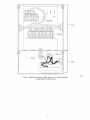
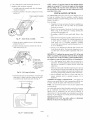
Refer to Fig. 1 and Fig. 3
FLOW
for minimum
C00L[NG
Piping:
required
Piping
clearances,
and insulation
is field supplied,
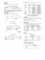
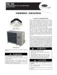
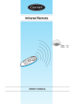
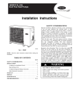
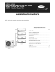
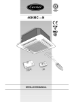
38HDF018-036
A09499
Fig.
4 - 38HDF018-036
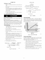
PiDinu Lenuths
The
minimum
(3 m).
length
Refer
to table
Table
BODY
between
the indoor
and outdoor
3 for the
maximum
lengths
3 - Maximum
Refrigerant
units
is 10 fl
allowed.
Line
Lengths
Unit
Size
Max Line
Length* ft(m)
Max Elevation
(ID over OD) ft(m)
Max Elevation
(OD over ID) ft (m)
18K
200 (61)
65 (19.8)
200 (61)
24K
30K
200 (61)
200 (61)
65 (19.8)
65 (19.8)
200 (61)
200 (61)
36K
200 (61)
65 (19.8)
200 (61)
Note:For lengths greater than 25 ft (7.6 m), refer to the Duct Free Long
Line Guide.
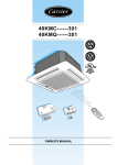
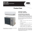
A09500
Fig.
Model
Filter Drier
38HDF
_*
38QRF
Multiple pistons.
Pipe
Sizes
Refer
to table
4 for
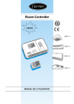
5 - 38QRF018-036
Piston
Cap
_*
_*
_* (qty 2)
Quantity varies with size.
pipe
sizes.
Table
Pistons*
_*
_*
Flare
Connector
_*
_* (qty 3)
4 - Pipe
Unit Size
18K
24K
30K
36K
3/8
3/8
Note:Both lines need to be insulated
insulation.
Condensate
Refer
Sizes
Pipe Sizes (in)
Mix Phase - in
3/8
3/8
to table
Vapor 5/8
5/8
3/4
3/4
using at least 1/2 inch closed foam
Drain Pipe Sizes
5 for
the required
Table
Unit Size
18K
in
sizes.
5 - Drain
Pipe
Inside
Sizes
Diameter
1
24K
30K
1
1
36K
1
- in
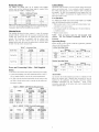
Refriuerant
Charge
Control Wiring
The 38HDF and 38QRF units can be matched with multiple
outdoor units and thus additional charge might be required when
matched with the 40KMC or 40KMQ units,
Table
6 - Additional
heat pumps.
Charge
Additional Charge Ib (kg)
Unit Size
38HDF
38QRF
018
0
0
024
1.2 (0.55)
0
030
3.0 (1.40)
1.8 (0.82)
036
0.8 (0.36)
0
Note:The above additional charge is required amount for line lengths up to
25 ft (7.6 m), For line lengths exceeding 25 ft (7.6 m), additional charge will
be required. Refer to the Duct Free SpfitsLong Line Guide.
Metering
The metering device(s) for these systems is a type B Accurator
installed with the outdoor unit. One Accurator
is required for the
cooling
only system and two are required
for the heat pump
The Accurators
are supplied
with
since the same outdoor
unit can
multiple indoor units, the correct Accurator
to Table 7 for the correct Accurator size.
the outdoor
be matched
unit.
with
must be selected.
Refer
Table 7 - Accurator
For 38HDF
Cooling
and 38QRF
units, the following
• Wall mounted
controlled
• Wireless
NOTE:
controls.
document.
control.
018
49
024
030
57
61
036
018
74
51
024
030
55
63
53
036
70
63
Only
Heat Pumps
• The indoor
• Consult
Connecting
and outdoor
local building
CEC (Canadian
• Use Table
Electric
codes,
a dedicated
NEC (National
requirements
and Table 9 for the indoor units to correctly
disconnect
Unit
Size
8 - 38HDF
Electric
that the system
for the outdoor
Operating
Electrical
Requirements
38HDF
38QRF
Min Ckt Amps/
Fuse HACR Bkr
Amps
12.1/20
16.8/25
030
035/36
208/230-1-60
208/230-1-60
18.4/30
23.8/40
18.4/30
23.3/35
035/36
035/36
208/230-3-60
460-3-60
18.0/30
8.3/15
14.5/20
8.7/15
Unit
Size
Voltage
within
the @plication
in
wired
this
guidelines
Range
Maximum
Minimum
WB°F (°C)
DB°F (°C)
Outdoor
Unit
125 (51.7)
--
55 (12.8)
Indoor
Unit
90 (32.2)
74 (23.3)
62 (17.0)
Operating
WB°F (°C)
-56 (13)
Range
Electrical
(°C)
Minimum
WB°F
(°C)
DB°F
(°C)
WB°F
Outdoor
Unit
75 (23.9)
67 (19.4)
17 (-8.3)
--
Indoor
Unit
81 (27.2)
--
62 (17.0)
--
(°C)
Accessories
list of field installed
Requirements
40KMC
40KMQ
Min Ckt Amps/
Fuse HACR Bkr
Amps
16.3/20
018
208/230-1-60
Min Ckt Amps/
Fuse HACR Bkr
Amps
0.8/15
024
030
208/230-1-60
208/230-1-60
0.7/15
1.3/15
16.3/20
16.9/20
036
208/230-1-60
1.3/15
16.9/20
accessories
is available
for both
indoor and outdoor units.
Identify what accessories,
if any, are
required
for the application
at hand and consult
the separate
installation
instructions
for the accessories.
Some
of the
accessories,
/ KMQ
operates
DB°F (°C)
An extensive
units
size the cables and
208/230-1-60
208/230-1-60
9 - 40KMC
mounted
section
tables,
Maximum
Code) or
018
024
Table
up
power supply.
Min Ckt Amps/
Fuse HACR Bkr
Amps
12.1/20
16.8/25
Voltage
up to 32 units divided
Range
especially
easier if planned
QRF
of controlling
are factory
ready
for wall
User
Interface
Installation
in the following
Heating
switches.
Table
and
control.
55
Code) for any special requirements.
8 for the electrical
and 40KMQ
46
Cables - Field Supplied
units require
with 40KMC
are available
Up to 6 units can be daisy chained
c@able
DB°F
Power and
Power:
50 and
zones.
Units
See
Heating
Accurator
Cooling
Accurator
units matched
accessories
remote
Operating
Cooling
Size
up to 50 ft
between
by one wired control.
• Zone manager
Ensure
Sizes
for any length
for lengths
the
for
on
User Interface
shown
System Type
18 AWG is recommended
(15.2 m). 16 AWG is recommended
200 ft (15.2 and 61.0 m).
to 8 different
Device
systems.
However,
Thermostat
wires should be used for control wiring between
indoor and outdoor units.
A two conductor
cable is required
the cooling only units and a seven conductor
cable is required
ahead.
on the indoor
units,
can be installed
much
INSTALLATION
Complete
Pre-installation
1. Unpack
original
NOTE:
Checks
exceed
Unit - Store the indoor and outdoor units in the
packaging
until it is moved to the final site for in-
stallation.
When unpacking
indoor unit, be careful not to
lift unit by condensate
drain discharge pipe or by refrigerant
connections.
2. Inspect
Shipment
- Upon
receipt
of shipment,
check
3. Inspect
Parts
is not responsible
Supplied
With
Units
-
Check
NOTE:
loss or damage,
Consider
System
1. Consult
leave all parts in original
codes
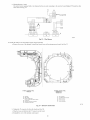
square
ceiling,
must
not
for the 40KMC018
units
for the 40KMC024-036
and
units.
The unit is in two sections:
a. Use the factory
supplied
The
unit and the grille.
cardboard
template as a guide
to mark the position of the hangers, refrigerant lines and
condensate
drain pipes, power supply cables and remote
control
cables.
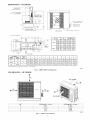
See Fig. 1 for dimensions.
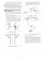
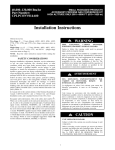
b. Depending
on the type of ceiling, fix the threaded
hangers as shown in Fig. 7 and Fig. 8.
in-
noti-
packages
until
--®
Requirements
local building
board
cutout
all items
against parts list (see page 4). If any items are missing,
fy your distributor or Carrier office.
To prevent
installation.
is in a plaster
of the unit housing
2 It, 2 in. (0.66 mm)
40KMQ018-036
the
for damage
location
dimensions
and 2 ft. 11 in. (0.66 mm) square
indoor and outdoor units for damage. If there is any damage, forward
claim papers directly
to the transportation
company.
Manufacturer
curred in transit.
If the mounting
the maximum
and NEC
for special
®
installa-
tion requirements.
2. When
deciding
the location
of the indoor and outdoor
ensure that the piping run does not exceed
tances listed in Table 3.
3. Make sure the indoor
to electrical power.
and outdoor
units,
the allowed
dis(T)
@
®
®
@
units are easily accessible
4. Allow sufficient
clearances
for airflow, wiring, refrigerant
piping, and servicing the unit. See Fig. 2 and Fig. 3.
5. Condensate
piping
to an approved
INSTALL
can be directed
drain or straight
INDOOR
Plan the installation
a. A location
NOTE:
Washer
Threaded
Washer
Nut
Nut
hangers
A07186
wall
Fig. 7 - Attaching
Hangers
to Ceiling
outside.
before
you begin.
unit location.
that can bear the weight
b. Install the unit a centrally
c. Choose
the inside
®
(_)
@
@
@
UNIT
carefully
1. Select indoor
through
Nut
Washers
Threaded hangers
Wooden frame
Nut
a location
A maximum
time. See Fig. 6. The Air Supply Outlet
kit can be used to obstruct
air outlets.
can
Threaded hangers
3:
in the room.
that does not obstruct
of two air outlets
_4._.___._/_
of the unit.
as possible
7=
be restricted
Obstruction
at one
(to be removed)
accessory
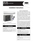
A07187
Fig. 8 - Threaded
m
c. Insert
¢-7='=-.--I
c-7=-=-c3
"T" ar
air circulation.
the washers
Hangers
as shown
and "T"Bar
in Fig. 7 and Fig. 8.
d. Remove the "T"bar in ceiling to facilitate installation.
See Fig. 8. If the "T" bar cannot be removed from the
{, )
ceiling,
9.
r------
Max.
2 louvers
the unit may have to be tilted as shown
in Fig.
closet
'l
T
T--7=--=-C3
_t
--"
T
1
_m,=_=_=_=___
T-Bar
T-Bar
A07184
Fig. 6 - Air Outlet
upenslon
• Brace
k s
Obstruction
Supension Brackets
A07188
d. Choose a location
and maintenance.
that is easily accessible
e. Do not install indoor
such as direct sunlight
units near a direct
or heating
Indoor
Unit
source of heat
appliance.
f. Do not install units too close to humid
2. Mounting
for service
conditions.
Fig. 9 - Positioning Unit in Ceiling
e. If Fresh Air Intake or Conditioning
is required, perform the modification
at this point. Refer to the Installation
for additional details.
an Adjacent
Room
required
Options
to the unit
section
£ Usea stacker
to lift the unit to the installation
INSTALL
location.
See Fig. 10.
OUTDOOR
UNIT
The outdoor units can be installed
mounted on a wall.
;k
NOTE:
Install
the unit
on the ground,
so that
the coil
on the roof,
does
not
or
face into
prevailing
winds. If this is not possible
and constant
wind
winds above 25 mph are expected, use accessory
wind baffle.
See installation
instructions
baffles
also
be used
temperature
control.
ambient
should
Mounting
Fig. 10 - Positioning
g. Carefully
[]nit
brackets
brackets
into the threaded
with
kit. Wind
accessory
low
is being
3. Position unit so water
onto unit.
installed,
pad.
use a field-
prolonged
provided
subfreezing
snow
temperatures
or ice from roof does not fall directly
4. On cooling only units, an accessory stacking kit can be used
when units are to be stacked. See installation
instructions
Spirit
False
Ceiling
unit on a solid level concrete
2. If a heat pump
stand or ice rack where
or heavy snow occurs.
lift the unit using the four suspension
and insert the four suspension
hanger as shown in Fig. 11.
with accessory
on all units
on Ground
1. Mount
A07185
provided
provided
Mounting
with the accessory
kit.
on Roof
to 1-3/16"
PERSONAL
INJURY
DAMAGE HAZARD
A07189
Fig. 11 - Align
h. Align
and Level
[]nit
and level the unit by adjusting
the nuts and lock-
3. Drill the hole for the piping (refrigerant
and control wiring in the external wall.
and condensate)
a. Drill a 2-3/4 in. (70 ram) hole in the wall with a 3/16
in. to 3/8 in. (4.8 - 9.5 ram) slope toward the outside.
Refer to Fig. 12.
_[
i/
EQUIPMENT
Failure to follow this caution
may result in personal injury
and / or equipment damage.
Be sure unit panels are securely in place prior to rigging.
1. Rig the unit.
nuts on the threaded hangers maintaining
a distance of 1
in. to 1-3/16 in. between the sheet metal body and the
underside of the false ceiling.
See Fig. 11.
AND/OR
Keep
the unit
upright
and lift using
a sling.
Use cardboard or padding under the sling, and spreader bars
to prevent sling damage to the unit. See Fig 13. See Fig. 2
for center of gravity
2. Mount
reference
unit on a solid concrete
pad or platform.
3. Isolate unit and piping
from structure
4. If a heat pump
installed,
is being
stand or ice rack where
or heavy snow occurs.
prolonged
use a fieldsubfreezing
provided
snow
temperatures
5. On cooling only units, an accessory stacking kit can be used
when units are to be stacked. See installation
instructions
•
provided
with accessory
kit.
SUNG
SLING PADDING
COMPRESSOR
END
A07190
Fig. 12 - Drilling
for Connections
4. Drill hole for Fresh Air Intake,
tion Options
NOTE:
In
insulated
using
rooms
section
with
self-adhesive
if required.
for additional
high
humidity,
Refer to InstallaCENTER OF
GRAVmTY
information.
brackets
should
be
insulation.
A07396
Fig. 13 - Lifting
[]nit with Sling
Mounting
Connection
Unit on Wall
at Outdoor
Unit
The units can also be mounted on the wall using the accessory
mounting kit.
Complete
tions
Outdoor
Refrigerant
Piping Connec-
Follow the following general guidelines:
1. Use refrigerant grade field - supplied tubing.
Refer to Table 4 for the correct line sizes.
2. Do not use less than 10 ft (93.05 m) of interconnecting
tubing.
[]NIT DAMAGE
HAZARD
Failure to follow this caution may result in equipment damage
or improper operation.
To prevent damage to unit or service valves observe
following:
• A brazing shield MUST be used.
the
• Wrap service valves with wet cloth or use a heat sink
material.
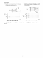
38HDF []nits:
[]NIT
DAMAGE
HAZARD
Failure to follow this caution may result in equipment
damage or improper operation.
If any section of pipe is buried, there nmst be a 6 in. (152.4
ram) vertical rise to the valve connections on the outdoor
unit. If more than the recommended length is buried,
refrigerant may nfigrate to cooler, buried section during
extended periods of system shutdown. This causes
refrigerant slugging and could possibly damage the
compressor at start-up.
1. Assemble the connector tube to the factory supplied filter
drier by:
a. Braze the field supplied connector to the inlet of the
filter drier (see Fig. 14)
b. Braze the factory supplied flare connector to the outlet
end of the filter drier (see Fig.14)
COOL[NG
FILTER
"/DRIER
PISTON
BODY
When more than 80 fl (24.4 m) of interconnecting tubing is used,
consult the Duct-Free Split System Long Line Application Guide
for required accessories.
3. Insulate both lines. A minimum of 1/2 inch foam pipe insulation is recommended.
4. Run the refrigerant tubes as directly as possible and avoid
unnecessary turns and bends.
5. Suspend refrigerant tubes to avoid damage to insulation or
tubes so they do not transnfit vibration to the structure.
A09499
Fig. 14 - 38HDF018-036
2, Assemble
factory
the Accurator
supplied
6. When passing refrigerant tubes through the wall, seal the
opening so rain and insects do not enter the structure. Leave
some slack in refrigerant tubes between structure and outdoor unit to absorb vibration.
NOTE: A fusible plug is located in unit suction line; do not cap
this plug. If local codes require additional safety devices, install
as directed.
Connector
body
Tube Assembly
(see Fig, 15) using the correct
piston (refer to Table 7),
TEFLON SEAL
\
_
_ _}__
TO INDOOR
_
COIL
PISTON
WITH ORIFICE
CAP
NOTE: Arrow on AccuRater
indoor coil.
_
\
BODY
body points in free flow direction, away from the
A09501
Fig. 15 - AccuRater
(bypass type) Metering Device
Components
3, Attach the complete Accurator
tion end of the filter drier
4, Braze the completed
liquid service valve.
filter
assembly
drier/Accurator
to the flare connec-
assembly
to the
5, Connect the field supplied line set to the filter drier/Accurator assembly and the suction valve. A sweat connection
is
required at the suction valve and flare connection
is required
for the nfixed phase
6. Insulate
any exposed
quid valve.
line,
areas between
the line set and the li-
38QRF
Units
1. Assemble the connector tubes to the factory supplied filter
drier by brazing the factory supplied flare connectors
to the
inlet and outlet
UNIT
for the filter drier (see Fig. 16)
DAMAGE
HAZARD
Failure to follow this caution
or improper operation.
A09507
2. Perform
Connector
Tube Assembly
step 2 and 3 from the 38HDF
cap supplied
with
section.
the outdoor
ELECTRICAL
SHOCK
HAZARD
Failure to follow
or death.
this warning
could
result in personal
iniury
Before performing
service or maintenance,
be sure indoor
unit main power switch is turned OFF and indoor blower has
stopped.
3. Remove the plastic cap from the liquid and suction service
valve on the 38QRF unit and assemble the heating piston
and piston
Fig. 17.
damage
Unit failure as a result of operation on improper line voltage or
excessive
phase imbalance
constitutes
abuse and may cause
damage to electrical components.
Such operation
could void
any applicable Carrier warranty.
BODY
Fig. 16 - 38QRF018-036
may result in equipment
unit as shown
in
Lock out and tag switch with a suitable
Power
warning
label.
Wiring
1. Mount outdoor power disconnect. The unit is factory wired
for the voltage shown on the unit nameplate. The fused disconnect switch nmst be provided within sight of the unit,
readily accessible, but out of reach of children. Provisions
for locking the disconnect switch on the OFF (open) position is advisable. The disconnect switch must comply with
NEC and local codes, Protect the unit and wiring using
only the recommended
fuse/circuit breaker size. See
Table 8.
--P ISTON
HEAT IN6
PISTON CAP
TOR
2. Run power wiring from main box to disconnect per NEC
and local codes.
L/
METEREDFLOW
"=HEATING
J]
3. Run power wiring from the disconnect switch to outdoor
unit. Use only minimum 60°C copper conductors between
the disconnect switch and the unit for field power connection,
A07407
Fig. 17 - AccuRater
Metering
Device
Heat Pump
NOTE:
The
Teflon
service
valve.
The
might
have to be adjusted
size
4. Route the field power wires through the conduit connection
opening in the unit side panel and connect in junction box
as shown in Fig 18. The unit and power wiring must be
grounded,
type)
Components
Systems
seal on the piston
liquid
of the
Only
should
point
factory
Free Long
Line
towards
supplied
for long line applications
/ 24.4 m). Refer to the Duct
for additional
information.
4. Attach
(bypass
TO--"
the
piston
(over
Application
80 ft
Guide
_-----
BLK
NGLE-PHAS7
the flare end of the filter drier assembly
to the piston
cap (see Fig. 17).
5. Connect
the field supplied line
sembly and to the suction valve.
6. Insulate
valve.
Complete
any exposed
Outdoor
set to the filter
areas between
Power
filter drier
and Control
drier
as-
and liquid
=d_
BLK
=_i
BLU --
=_::_-
YEL
THREE-PHASE
CONNTO
DISCONNECT
PER NEC
Wiring
=GROUND
LEAD,
._]
GROUNDING
THREE-PHASE
ELECTRICAL
SHOCK
Failure
death.
this warning
to follow
could result in personal
injury
or
Code
A08251
The unit cabinet must have an uninterrupted
or unbroken
ground to minimize personal injury if an electrical fault should
occur. The ground may consist of electrical
wire or metal
conduit
codes.
LEGEND
NEC -- National Electrical
-- Splice (field)
-- -- ' Field Wiring
Factory Wiring
HAZARD
LUG
UNIT
when
installed
in accordance
with
existing
electrical
Fig. 18 - Line
NOTE:
Operating
abuse
and
in
system
a
permissible
9
may affect
where
limits.
unit
on
Carrier
voltage
Power
Connections
improper
line
warranty.
may
voltage
DO NOT
fluctuate
above
constitutes
install
or
unit
below
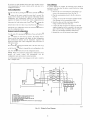
Control
Wiring
2, Route one end of the control wiring through the opening
provided in the unit side panel and connect to the control
terminal strip using either Fig. 19 for 38HDF units and Fig.
20 for 38QRF units,
The control circuit is 24 volts AC (naininmm 40VA) supplied from
the indoor unit,
1. Make sure you have enough control wires to cover the distance between the indoor and outdoor unit,
Indoor
Terminal
Board
Indoor_
Board
Indoor _
_4v
Board
COHPR
Terminal
Board
T
°v2°;
Outdoor
Board
...... _o i41_i_
_
.............
_o _LL
r_
I_ I
Board
A09509
A09508
Fig. 19 - 38HDF
NOTE:
Use No. 18 AWG
greater
than
voltage
drop.
100 ft. (30.5
Control
Terminal
color-coded,
Strip
insulated
m), as measured
Fig. 20 - 38QRF
along
(35°C
minimum)
the control
wire.
voltage
wires,
10
If the distance
Control
between
use No. 16 AWG
Terminal
the indoor
color-coded
Strip
and outdoor
wire to avoid
unit is
excessive
ELECTRICAL
DATA
Table
38HDF/38QRF
UNIT SIZE
10 - 38HDF/38QRF
VOLTAGE RANGE*
Electrical
COMPRESSOR
Data
OUTDOOR FAN MOTOR
V-PH-Hz
Min
Max
RLA
LRA
FLA
NEC Hp
kW Out
MIN CKT
AMPS
FUSE/
CKT
BKR
AMPS
018
208/230-1-60
187
253
9.0
48.0
0.80
0.125
0.09
12.1
2O
O24
208/230-1-60
187
253
12.8
58.3
0.80
0.125
0.09
16.8
25
36QRF030
208/230-1-60
187
253
14.1
73.0
1.50
0.25
0.19
18.4
3O
36HDF030
208/230-1-60
187
253
14.1
73.0
0.80
0.125
0.09
18.4
3O
208/230-1-60
187
253
16.7
79.0
1.50
0.25
0.19
22.3
35
208/230-3-60
187
253
10.4
73.0
1.50
0.25
0.19
14.5
2O
460-3-60
414
506
5.8
38.0
0.80
0.25
0.19
8.7
15
208/230-1-60
187
253
17.9
112.0
1.45
0.25
0.19
23.8
4O
208/230-3-60
187
253
13.2
88.0
1.45
0.25
0.19
18.0
3O
460-3-60
414
506
6.0
44.0
0.80
0.25
0.19
8.3
15
035
036
Table
11 - 40KMC
Fan coil Electrical
Voltage Range
40KMC
Unit Size
V-PH-Hz
018
024
Data
Power
FAN
Condensate
Louver
Motor
FLA
MIN CKT
AMPS
FUSE/
CKT
BKR
AMPS
Min.
Max
FLA
Wafts
Pump FLA
208/230-1-60
187
253
0.55
120
0.06
0.01
0.8
15
208/230-1-60
187
253
0.50
110
0.06
0.01
0.7
15
030
208/230-1-60
187
253
0.95
210
0.06
0.01
1.3
15
036
208/230-1-60
187
253
0.95
210
0.06
0.01
1.3
15
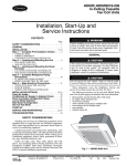
Table 12 - 40KMQ
Voltage
Range
40KMQ
Unit Size
Fan Coil Electrical
Data
Electric
Heaters
FAN
Pump FLA
kW
FLA
MIN
CKT
AMPS
Condensate
V-PH-Hz
Min.
Max
FLA
Motor
Power
(Wa_s)
Power
Louver
Motor
FLA
FUSE/
CKT
BKR
AMPS
018
208/230-1-60
187
253
0.50
110
0.06
0.01
3
12.5
16.3
2O
024
208/230-1-60
187
253
0.50
110
0.06
0.01
3
12.5
16.3
2O
030
208/230-1-60
187
253
0.95
210
0.06
0.01
3
12.5
16.9
2O
036
208/230-1-60
187
253
0.95
210
0.06
0.01
3
12.5
16.9
2O
*Permissible limits of the voltage
range at which unit will operate satisfactorily.
LEGEND
FLA
MCA
NEC
-
Full Load Amps
Minimum Circuit Amps per NEC Section 430-24
National Electrical Code
RLA
-
Rated Load Amps (Compressor)
NOTES:
1. In compliance with NEC requirements for multi-motor
and combination
load equipment (refer to NEC Articles 430 and 440), the over-current
protective device for the unit shall be fuse or equipped with a breaker.
2. Motor RLA values are established in accordance with UL (Underwriters
Laboratories) Standard 465.
@s
11
OISPLAY
P__
_pce
TH COIL
I
REO
RED
2
3PL4
/
___
TB2!_
TM AIR
ill
I
_
TB1
NODULAR
CONTROL
}
"D"
1PCB
F
GRA
_F
p•
...............
s ....
1_
1P
BLK__oR_HTwHT
1
.........
GRA_
1FC
40KNC
38HDF
GLOBAL CASSETTE
OUTDOOR CONDENSER
8LK _"
TO CASSETTE
Y
CASSETTE
R
_L--TO
NOTES
LEGEND
7
o
_;_aH_NA
US _
SHAH,
H_N_MUM
OR
SO"C
CARR
NRE
THERMISTOR
TEMPERATURE
rR
FOR
ROOH
THE
CONTROLLrR
FELD
{CRC}
pOIJER
CUkM'C_ON
*HR[NG
EQUIVALENCE
RESISTANCE
°F
°C
95
35
6,500
72
22
11,400
32
0
32,
SO0
ALL THERH[STORS ARE IDENTICAL
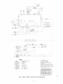
50057
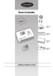
Fig. 21-
40KMC/38HDF
Cooling
Only
12
System
Wiring
Diagram
DISPLAY
COHM
TB3
RED_
i
_
_R_
_
_
.............
i
BARE COPPER
TO UNIT DISCONNECT/
(USE CABLE PRO/IDED}
6ND
DUIP.
PL
/FC
\
40KMO
_SH)F
(L(}I}A,L
L T)(L
H
(}A
<
ETTE
..... S /Es
C
£ED
E
I
o)
OTE
YEL
8LK
7_
_
_
_qEE
[IS_
*;LK_]]LT(
LK EO'!2:
......
........
NE}T
A :ETTE
2
[(
LEGEND
(AS
b
Y
ETTE
: )
2
.......
[_A_ED
+E
_C
7
i
_
T R_P_A
OU
TIE
ST,
_
_CTO
b*
OR
UN
*_LAC_
_]RE
80NCI
DN
0
0
_ST_[
F_R
C_RR]ER
_ 50_HR
TO E
S
2O,
THERH[STOR
BE
JNSE_
*rRC"
ON_TeR)
ROOH
AClO
CONTROl
O[
E,_
'_IRO
"
S"
OR
(CRC2
D_
q p
JR
CON
23@_
_C
OPTON
ECT[O_
OR
2O8,'
.O_E
A
EOU[VALENCE
TEMPERATURE
RESISTANCE
95
3S
B,SO0
/2
22
1/,400
32
0
32,500
ALL THERMISTORS ARE IDENTICAL
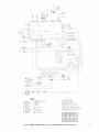
50058
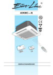
Fig. 22 - 40KMQ
/ 38HDF
Heat/Cool
System
Wiring
13
Diagram
with
Electric
Heaters
.............................................
THCILTHAIR
_OhJ
_0_
L8
_
1
_
)
K_
HODULSI: "D"
('ONT _OL 1P(
40KPO
180
GLOBAL
C#
!}ETTE
F OUTOOOR COS[}E",!E
....
S
TO
CASSETTE
TO
C_SE_ETTE
B
A
TO
CASSETTE
DT
G
_/I
i
TO
CASBETTE
EB
.......
TO
CASSETTE
133
.......
TO
{:ASSETTE
r_L_
Y
.....
//I
R
/
DS
TS_,
I.J[GEND
uiE;
El ICll
I
iCAl
lolIrllso_
COl
i rl
{O!PRIiBOR
IIERIIL
i
}NOO(R
IN}
PIE
PR]IARY
7
ERIINAL
}NNIIRiB
Pli
Ai
1
10
(H
f in
i
IIo_I
AN)
AN
O_ERLOAIS
i
{}I
At
iOR
MI!I!IU_
80+1
A
THERH[STOR
TEMPERATURE
+F
'C
SS
_D
@R
IY
2=
IIOH
{NIIAIIID
FIOTOI
AP
HII
ON
{R
if10l
"J} =
R)R
18R6
IIRE8 Ol
IE[D
olelldl
]IIIRIA{
ilRIAI
CONTROLLSR
18111O11,
FOR
130,
POIE_
[
RE j,_ !
R
OP
ION
80NXECT]OI
+I
OR
!IOR
2!1'_
0i0
IO,E
II_iNI
E U[VALENOE
RES [STANCE
6, O0
?
!
_II_IiI
I0
!RNA{
N 18 Ii
HIIIRiE;
1[!8
"CRO"
101111
HiASR 11
2111
RO?IC
IN
ClRRJER
II_E
COgll
b_ [rllnll
ARI
l_S
ION_q!C11
_II
I{;101
STRIP
I IC>i
I_otl_id
?RAISIORI_!R
51D£
CO!PRSIBOR
OUTDOOR
UNIT IRAHIIIAil
IANIFORME!
IPiE }[AOI
I}Ri
10
HI
8]E
A_l)
irl
!OiORl
, 400
0
3,
,00
ALL THER'¢I',TORIi ARE IDENTICAL
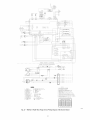
50059
Fig. 23 - 40KMQ
/ 38QRF
Heat Pump
System
Wiring
14
Diagram
with Electric
Heaters
Run Power
Wiring
for Indoor Unit
Be sure field wiring complies with local building codes and NEC,
and unit voltage is within linfits shown in Table 11 and Table 12.
Contact
voltage.
local
power
company
for correction
of improper
line
NOTE:
Use
and unit.
NOTE:
handle
within
440-14
copper
Failure to follow
or death.
this warning
could result in personal
with outdoor
2. Locate
codes.
Before
installing,
modifying,
or servicing
system,
main
electrical
disconnect
switch nmst be in the OFF position.
There nmy be more than 1 disconnect
switch. Lock out and
tag switch with a suitable warning label.
DAMAGE
may result in equipment
install
of adequate
size to
Locate
disconnect
from, unit, per section
indoor
unit to share
can be locked;
check
their own power supply.
supply.
disconnect
supply
wiring
4. Run power
wiring
from
switch
per NEC
to disconnect
disconnect
and local
switch.
switch
to control
box
area. Use copper wire only between the disconnect
switch
and unit. Use minimum
60°C wires for field power connection.
HAZARD
Failure to follow this caution
or improper operation.
and
power
3. Run power
5. Remove
[]NIT
disconnect
per NEC.
switch(es)
in this manner.
units require
1. Locate the indoor
disconnect
unit if disconnect
installing
The 40KMC/KMQ
injury
between
sight of, and readily accessible
of NEC. Some
codes allow
local code before
HAZARD
only
Install branch
circuit
unit starting
current
disconnect
ELECTRICALSHOCK
wire
the external
control
box cover.
6. Place wiring through the 7/8 in. or 1-1/8 in. knockouts
on
the bottom and on the right hand side of the external control
damage
box (high voltage
Unit failure as a result of operation on improper line voltage or
excessive
phase imbalance
constitutes
abuse and may cause
damage to electrical components.
Such operation
could void
any applicable Carrier warranty.
15
side).
See Fig. 24 and Fig. 25.
Room Controller
Connections
Outdoor
Unit
Connections
O
II
I
II
I
II
I
II
I
II
I_-
II
I
II
I
II
I
II
I
II
I
II
I
Low
Voltage
Con nection
_:
High
Voltage
A07208
Fig. 24 - 40KMC
Unit Matched
to 38HDF
(Cooling
Only
Outdoor
System)
16
Unit - Wiring
Connection
lOW
Voltage
_m
©
Voltage
A07209
Fig. 25 - 40KMQ
Unit Matched
(Cooling
to 38HDF
Outdoor
with Electric
Unit - Wiring
Heat System)
17
Connection
7. Connect
L1 to the black wire and L2 to the red wire using
wire nuts and fix the ground
The internal
and removing
control
wire between
panel can be accessed
the metal cover attached
NOTE:
The internal
during
the installation
control
panel
process
d. Lubricate
the two washers.
by opening
with refrigerant
then use two wrenches
nections fully applying
Table 13.
the grille
by four screws.
does not need to be accessed
unless
the end of the pipe and thread
connection
of the flare
oil. Tighten
by hand
and
(see Fig. 28) to tighten all conthe tightening torque shown in
there is a need for service.
8. If any accessories are being installed, refer to the individual
accessory instructions
for guidance on wire routing at this
time.
Install
Drain
All
Hose
Power_ Interconnecting
to Indoor
Unit.
1. Run control wiring
Wiring_ Piping
from the outdoor
and
unit through the access
hole in the wall and make sure you have enough wire to
reach the control box of the unit once hung on the mounting
plate.
2. Complete
refrigerant
piping
@ Outdoor end
n or _orque wrench
-_\
@ Indoor end
&...._
_
\
"-/
A07201
connections.
a. cut the extreme end of the tubes and remove
shavings with a de-burring
blade.
Fig. 28 - Tightening
any copper
b. Remove the flare nut from the "Flare" connection
of the indoor unit and insert them into the pipes.
Connections
Table 13 -TighteningTorque
body
TUBE DIAMETER (in.)
3/8 in.
c. make the flares to the pipe ends with the proper flaring
TORQUE fft.-Ib)
31
5/8 in.
3/4 in.
too. The flare end nmst not have any burrs or imperfections, the flared walls must be uniform.
See Fig. 26
and Fig. 27.
48
74
_)
(f)
@
Indoor unit piping
Connection
w_ring
@ Drain hose
_--_
A07199
Fig. 26 - Removing
r _f_
Burrs
J
I
I
A08364
Fig. 29 - Location
i
3,
I
I
I
I
Hose,
and Wiring
Connect
Observe
condensate
drain piping
all local sanitary codes when installing
drains.
The condensate
may be discharged
condensate
at a maximum
height of 7-1/8 in, (181 ram) above the unit as long as the
ascending tube is vertical and aligned with drainage flange.
If it is necessary
to discharge
the condensate
from
a level
above 7-1/8 in. (181 ram), install an auxiliary water discharge pump and a float valve. A float valve is recommended to stop the compressor
if there is a fault at the auxiliary
i
I
I
pump.
I
A07200
Fig. 27 - Flared
of Piping,
Walls are Equal
18
a.Usehard
polyvinyl
chloride
(PVC)
pipematerial
with
nominal
IDof1in.toconnect
atdrain
line.Toensure
correct
condensate
water
flow,thepipeshould
have
a
gradient
of2%without
obstruction.
See
Fig.30
b. A trap of at least 2 in. (51 mm) in depth should be made
to prevent unpleasant odors from reaching the room.
c. Insulate
4. Complete
PERSONAL
Failure
INJURY
to follow
The drain
condensate
this caution
water dripping
pipe with condensation
Control
propylene,
proof mater-
or neoprene
of 3/16
Wiring
a. Route the control wiring through the 7/8 in. knockouts
on the left or right hand side of the external control box
HAZARD
tube extension
drain. Failure
condensate
ial such as polyurethane,
in. to 3/8 in. thickness.
may result in personal
injury.
(low voltage
must be securely fastened
to the
to do so could result in condensate
b. Connect
side).
R and Y wires to the terminal
block for cooling
only units (40KMC) and heat pump units (40KMQ)
that
are matched with the 38HDF outdoor units. See Fig. 24.
on to the floor.
c. Connect
the R, Y, O, G, DT, A, and B wires to the
(PGB-1)
1 terminal
units. See Fig. 25.
on the 40KMQ
heat pump
indoor
5. Perform any modifications
required for the accessory user
interface. Three types of user interface can be used with the
unit: Wall mounted
and Zone Manager.
a. Wall Mounted
wired
Remote
control,
Wireless
remote
control
Control
The unit comes ready from the factory for use with a
wall mounted wired control. Refer to the installation
instructions
information.
of the wired remote control for additional
The wall mounted wired control connects
to terminals
P, G, and C located
in the external
control
box. See Fig. 24 and Fig. 25. If there is a desire to
control multiple units (up to 6) from one wired
remote
control,
the units should
be wired
as shown
in Fig. 31.
A07191
Fig. 30 - Condensate
UNIT1
Drain
Pipe
UNIT
UNIT
3 ---
UP TO 6 UNITS
__J5
5
(9
(9
®
(9
A
*@
J
- MAIN
BOARD
(9
" WIRING
(9
" BLACK
(9
" RED
(9
- WHITE
KIT 33MC9005
* 100 ohm Resistor
!
A09513
Fig. 31 - Multiple
Unit
Control
19
Wiring
b. Wireless
Remote
Control
The unit is factory equipped
end is loose. See Fig. 32.
with a wire harness
that has one end connecting
to the receiver
4----
5 4J_ 2 1
board
(Display
PCB)
and the other
End
Loose
1S
1_12131_151
1_12131_151
A
I
Jll
I
I
J8
I
I
Js
I
A09547
Fig. 32 - Wire
To modify
the unit for use with wireless
a. Remove
remote
the cover of the Internal
Harness
do the following:
Control
Panel to get access to the microprocessor
board.
See Fig. 33.
®
®
INTERNAL
CONTROL
40KMC018
PANEL
INTERNAL
CONTROL
40KMC024-036
PANEL
40KMQ018-036
@
Capacitor
[]
Fan
@
@
GMC board
Electric
heater
board
(only on modets
with
[]
LED/RECEIVER
[]
Float
[]
Pump
[]
Louver
@
Transformer
@
Holes
@
Emergency
for fixing
panel
etectdc
heater)
in position
connector
connector
connector
connector
connector
push-button
A07180
Fig. 33 - Internal
b. Unplug
(A) from the board
(see Fig. 32).
c. Plug the Loose end (B) into the J5 Connector
on the board
d. Reinstall
the J5 connector
the cover of the internal
control
Control
panel
20
Panel
If you have two units installed
in the same space and they need to
work independently,
the remote
configured as follows:
controls
and the units
need to be
Unit Configuration
Zone Manager
If a Zone Manager
is required,
the following
steps should be
performed
at the same time the indoor control and power wiring
are being connected:
A
Turn the unit off by pressing
=_/_/IIbuttons
display
of the remote
will be cleared
control
of both
for more
and the time segments
configuration
item (rAdr=remote
segments will display the default
(ab=control
indoor
and
a. Remove the cover of the Internal Control Panel to get
access to the microprocessor
board. See Fig. 33.
The
b. Plug the communication
the IQL). Press and hold the/_
than 5 seconds.
the first
Fig. 34.
address)
and the temperature
value of this configuration
item
c. Connect
units).
will display
Press A and V to change
d. Route
the ;'/_ button
,,..a.,,
to the unit. Press the 1_ button
to
transmit
to
the new configuration
leave the configuration
e. Connect
supplied
Remote Control Configuration
A
Turn the unit off by pressing
and
buttons
for more
the IQL) button.
than
control
Press and hold the
5 seconds.
The
display
will
f. Reinstall
v
with the
board.
along the
the other end of the wire harness
wiring
in
to the back of the unit.
that will be connected
ager as shown in Fig. 34 (shielded
Refer to Zone Manager Installation
menu.
supplied
to the communication
the other end of the wire harness
voltage
default value to the new value of (a) or (b). Press
to the J8 as shown
one end of the wire harness
Zone Manager
the
board
the cover of the internal
to the field
to the zone man-
cables are required.
Instructions).
control
panel.
be
cleared and the time segments will display the first configuration
item (CH=remote
address)
and the temperature
segments
will
display the default value of this configuration
both indoor units).
Press A and V to change
the default
or (b). Press the ;'/_
to transmit
unit. Press the 1_
NOTE:
When
pressed,
the
configuration
button
button
menu
and resume
A wall mounted control
unit or multiple units.
the new configuration
have elapsed
control
of
value to the new value of (a)
to leave the configuration
30 seconds
remote
item (Ab=control
menu.
and no buttons
will
automatically
its normal
operation.
or zone manager
to the
have been
exit
can be used to control
the
a
®
WHITE
@
GREY
®
,.-.\
-F-.
_
-- t---- ,1-i
®
;I
! ,,
"'
]
J8
®
6
/
ii i i i
I
®
(_)
0
0
@
0
(_)
O
Main board
Communication
board
5-cable wiring (supplied
Auxiliary terminal block
Wiring by the installer
Zone Manager terminal
Indoor unit
L,,I
I®
r
±
Zcx_
t.0
t.O
(suppl}ed with the kit)
with the kit)
(supplied with the kit)
block (mounted on the Zone Manager)
A09514
Fig. 34 - Wiring
for Zone
21
Manager
6. Carry
a final check to make sure that the unit is level
NOTE:
supply
7. Install the Grille and Frame Assembly
a. Carefully
sustained
unpack the assembly
in transport.
b. Attach the assembly
See Fig. 35.
and check for damage
to the unit by using the two hooks.
into
Gasket
"A"
prevents
air and gasket
the ceiling
return
"B" prevents
void.
Once
air from
and false
support
brackets
with the
air from leaking
the unit is mounted
the gap between
the unit frame
more than 3/16 in. wide.
INSTALLATION
Frame
mixing
the supply
in the ceiling,
ceiling
must
not be
OPTIONS
The 40KMC,KMQ
units can be used to cool an adjacent room or
for fresh-air
ventilation.
Plan the installation
carefully. Measure
carefully and follow acceptable building practices and the National
Electric
Code (NEC).
Fresh Air Intake
1. Using Fig. 38, locate and remove the factory-installed
insulation from the side of the unit where the pre-punched
knockouts are located.
2. Remove
the pre-punched
knockouts
for fresh air intake.
Refer to Fig. 38. Be careful not to damage internal parts
such as the heat exchanger coil.
3. If installing
38.
A09548
Fig. 35 - Attach
Frame
c. Tighten the factory supplied
position. See Fig. 36.
d. Link the electrical
cable clamp.
connectors
a 40KMC018
4. Install ductwork
Assembly
insulated
unit, install baffle.
using field-supplied,
sheet metal
suitable
Refer
insulated
for working
flex duct, or
temperatures
to 140°F (60°C).
Conduits
can be of flexible
(with spiral core) or corrugated
aluminum,
covered with anti-condensate
material (fiberglass
screws to fix the frame in
and insert the wires in
to Fig.
up
polyester
externally
from 1/4
in. to 1 in. thickness).
See Fig. 36.
5. Use Fig. 39 to determine
the allowable
static
pressure
loss
for the ductwork airflow. The ductwork design must not exceed this value or the job airflow requirements
will not be
met.
IMPORTANT:
airflow
@ Safety cord
@ Cable clamp
@ Power
cables
@ Power
cables
@ Frame
screws
10 % of the total airflow,
system
See Fig. 37.
fan if airflow
non-insulated
ducts
densate insulation
thickness).
does
not meet
job re-
port to prevent
must
(such
Air Supply
as
be covered
expanded
to Adjacent
Room
with
anti-con-
neoprene,
1/4
-- Air supply
in.
to an
adjacent room requires that the outlet corresponding
with the duct
is closed, using the air supply outlet obstruction accessory kit.
NOTE:
The accessory
an electric heater.
kit cannot
be used in units equipped
with
An air inlet grille must be fitted (if possible near the floor) between
the air conditioned
room (where the unit is situated)
and the
adjacent
room or, alternatively,
the door nmst be undercut,
as
shown in Fig. 38. The duct lengths can be calculated in accordance
'W'
with Fig. 39, also taking into account
diffusers and fresh air filters.
IMPORTANT:
DO
NOT
filter kits for ducts towards
A09550
Fig. 37 - Gasket
primary
is recommended.
dust and dirt from entering and fouling the indoor unit heat
exchanger. Filter installation
also makes the installation of a
duct closing damper during shutdown
periods unnecessary.
Conditioned
,G
A. Gasket
a field supplied
deflectors
7. Install an air inlet grille with filter inspection
8. All
////////////,/_///////
of the total
If the ventilated
quirements.
The field-supplied
fan motor for outside air intake nmst be controlled
by a bipolar ON/OFF switch with
safety fuses.
in Position
the air inlet and outlet.
with separate
6. Use a field-supplied
connection
from unit
connection
from frame
support
10%
will result.
air treatment
e. Ensure that the frame is not distorted by excessive tightening, that it is aligned with false ceiling and that there
is seal between
air must not exceed
with operation
air surpasses
A09549
Fig. 36 - Fix Frame
Ventilated
or problems
Location
22
use
the pressure
active
adjacent
carbon
rooms.
drop through
or electrostatic
air
®
®
®
®
0 Duct connection
flange
(_) Clip
® 1/4" (6 ram) neoprene gasket
®
Unit
5-29/32"(150
B
O C
NOTE: Dimensions
40KMC024, 03036
40KMQ01824, 03036
40KMC018
OA
mm)
5-29/32"(150
(_ Insulated flexible
(_) Fresh air intake
mm)
4-3/4"(120 ram)
4-3/4"(120 ram)
2-3/4"(70 mm)
3-15/16"(100 ram)
duct
(_) Conditioned
air supply to an
adjacent room
® Polystyrene
partition
® Baffle (40KMC018 Only)
in ( ) are in mm.
(_) Frame
Air intake grille
(_) Wall
® Undercut
@ Wall-fitted
(_) Door-fitted
door
grille
<
i
grille
@
@
A09551
Fig. 38 - Installation
Options
Supply
air duct
to adjacent
room
0.18
0.16
0.14
0.12
,¢
40KMC,KMQ
0.1
03036
/
0.08
\
\
0.06
/
40KMC018,024
40KMQ01824
0.04
x
uJ
\
.i
0.02
0
0
50
1O0
200
150
Airflow
250
(cfm)
NOTE: When two louvers are closed, the fresh airflow towards the adjacent room
is 50% higher than when one louver is closed (with equal static external pressure)
A07178a
Fig. 39 - Pressure
Drop
for Conditioned
Air Supply
23
to an Adjacent
Room
(one louver
closed)
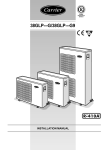
START-UP
Preliminary
Manifold Gage
Checks
1. Make
tight.
sure all wiring
2. Field electrical
plate rating.
power
connections
source
are correct
must
agree
and they are
with
unit
500 microns
side valve
name
3. Check that all barriers, covers, and panels are in place. Ensure that the filters and return-air
grilles on the indoor unit
have been installed
tioned correctly.
4. All service
valves
and that the discharge
louvers
_
low
Charge
..-'," _
L_
High side
hose--_
_,d
hose
are posi-
must be closed.
[_4
5. On units with crankcase heaters,
are tight around the compressor.
Evacuate
Charge
valve
and Dehydrate
ensure
belly-band
__//Vacuum
heaters
pump
//
\
Low side
the System
valve
A07361
Fig. 41 - Manifold
Deep
[]NIT DAMAGE HAZARD
Failure to follow this caution may result in equipment damage
or improper operation.
Never use the system compressor as a vacuum pump.
Refrigerant
tubes
and indoor
coil should
be evacuated
using
Vacuum
Method
The deep vacuum method
requires a vacuum
pump capable
pulling a vacuum of 500 nficrons and a vacuum gage capable
accurately measuring
is the most _ositive
the
liquid
water.
of
of
this vacuum depth. The deep vacuum method
way of assuring a system is free of air and
See Fig. 42)
recommended
deep vacuum method of 500 nficrons,
the alternate
triple evacuation
method may be used if the procedure
outlined
below is followed.
Always break a vacuum with dry nitrogen.
[]sing
Vacuum
Pump
valve.
2. Connect
(See Fig. 40.)
charge
hose to vacuum
pump.
3. Fully open the low side of manifold
4. Start vacuum
5. Evacuate
method.
LEAK IN
SYSTEM
if)
Z
O
ivO
m
1. Completely
tighten flare nuts A, B, C, D, connect manifold
gage charge hose to a charge port of the low side service
gage.
.VACUUM TIGHT
TOO WET
(See Fig. 41)
TIGHT
DRY SYSTEM
pump
using
either
deep
vacuum
or triple
evacuation
1
6. After evacuation
is complete,
fully close the low
manifold gage and stop operation of vacuum pump.
8. Disconnect
charge
side service valve.
hose from charge
9. Fully open service
valves
10. Securely
tighten
connection
up to
of the low
Triple
Evacuation
4. Close service
to 28 in. of mercury
for an additional
valves
a nitrogen
open until system
Low Side
and shut off vacuum
cylinder
pressure
and allow pump
to
15 nfinutes.
pump.
and regulator
to system
and
is 2 psig.
valve and allow system
to stand for 1 hr. Dur-
ing this time, dry nitrogen will be aMe to diffuse throughout
the system absorbing moisture.
Valve
5. Repeat this procedure
as indicated in Fig. 43. System
then be free of any contanfinants
and water vapor.
A07360
Fig. 40 - Service
down
operating
2. Close service
Indoor Unit
High Side
Service
Graph
Method
1. Pump system
3. Connect
_B
7
vacuum and system does not contain any liquid water.
Refer to Fig. 43 and proceed as follows:
valves.
Refrigerant
6
The triple evacuation
method should only be used when vacuum
pump is only capable of pumping
down to 28 in. of mercury
continue
Outdoor Unit
5
A95424
B and A.
caps of service
3
4
MINUTES
Fig. 42 - Deep Vacuum
7. The factory charge contained in the outdoor unit is good for
up to 25 ft. (8 m) of line length. For refrigerant lines longer
than 25 ft (8 m), add 0.3 oz. per foot of extra piping
the maximum
allowable length.
2
side of
Valve
24
will
Service Test mode automatically times out after 30 minutes and the
remote will operate normally.
IEVACUATE I
l BREAK VACUUM WITH DRY NITROGEN I
Test Mode
IEVACUATE
I
IEVACUATE
I
I CHECK
TIGHT,
SYSTEM
(IF IT FOR
HOLDS
DEEPDRY
VACUUM)
•
The unit Status (Green) and Timer (Yellow) LEDs will
blink every 2 seconds (see Fig. 45).
•
Indoor fan will operate according to user - selected
speed. If Auto fan is selected, the fan will run in High
speed
Cooling only system
I
•
INTO SYSTEM I
-- Unit will operate in cool mode with demand
-- Louver will operate according to user - selected
position or in cool position if louvers are set to
Auto
A95425
Fig. 43 - Triple
Evacuation
Method
To Start the Unit:
•
the system
12 hours before
starting
3. Set the wireless
low ambient
4. Refer
remote
control
temperature.
to Table
or wired
Operate
-- Unit will run in heat pump mode with demand for
2 minutes or until indoor coil temperature is
greater than 104°F (40°C). If coil temperature
reaches 104°F (40°C), the unit will run in cool
mode until test mode is exited.
the system.
2. Release charge into the system by opening
liquid and suction line service valves.
(back-seating)
remote
control
be-
the unit for 15 minutes.
6 to determine
if additional
charge
-- Louver will operate according to user - selected
position or in cool/heat position if louvers are set
to Auto.
is re-
quired. Also, if you have a long line application,
refer to the
Duct Free Long Line Application
Guide to determine the
additional
5. Calculate
charge
that is required
the total additional
beyond
in cooling and heating
demand or not.
charge required
test. In test mode
(on heat pumps)
Set Unit in Test Mode Using Wireless
Turn power
the A
and weigh
The
remote
control
display
the
transmit
the service
completed
will
Srcl=service
press the I_
NOTE:
When
pressed,
the remote
and resume
test
test signal
button
30 seconds
control
its normal
and
mode.
-- 30 minutes elapsed
-- Fail Mode
if there is
control.
control
8. Visually check that the condensate is being discharged from
the unit. If the unit is running in heating mode, the condensate needs to be checked and the following needs to be performed:
Press
the
Press
a. Remove grille and frame from the unit.
b. On the opposite side of the drain connection, insert a
water bottle up into the fan coil unit and fill drain pan.
See Fig. 44. Water must flow regularly with condensate
pump energized. If not, check the pipe slope or see f
there are any pipe restrictions.
NOTE: The unit is equipped with a safety float switch
to de-energize the compressor if the drain pan water
level gets too high.
for 5 seconds.
the time
to the unit.
segment
5"/_
After
will
button
to
test
has
the
to leave the test menu.
have elapsed
will
regardless
and no buttons
automatically
Following will cancel Test Mode:
-- Unit is turned off by controller
-- Power is cycled during Test Mode
and care-
the unit will run
in remote
on the remote
be cleared
in.
Remote
on to the unit. Insert batteries
and the =_/_/IIbuttons
•
25 ft (7.6 m).
6. Charge should be added as liquid (not gas) slowly
fully to low side to avoid liquid slugging.
7. Start unit with operation
Heat pump system
-- Unit will run in cooling mode with demand for 3
minutes
1. If the outdoor unit is equipped with a crankcase heater, turn
on the indoor and outdoor disconnect
switches to supply
power
of Operation
When in TEST MODE, the unit will operate as follows:
IBREAK VACUUM WITH DRY NITROGEN I
I RELEASE CHARGE
Sequence
Once unit is in TEST MODE, all remote control messages are
ignored except for a message to turn the unit OFF. Buzzer will
beep twice.
have been
exit the test menu
operation.
Set Unit in Test Mode Using Wired Control
There
is a hidden
service
test mode
that is initiated
through
a
combination
of button
presses when the remote
is off.
The
following combination
must be pressed within a 6 second period:
"DOWN-FAN-UP
Once
in service
-FAN-MODE"
test mode,
the service
sent and "Sr" will be displayed
"DOWN" button is pressed.
test mode
in the temperature
During Service Test mode, all the icons
that is active is the "DOWN"
button.
are off.
To cancel Service Test mode, press the "DOWN"
normal message with "OFF" mode.
message
icons
will be
until the
the only button
button
to send
a
A09552
Fig. 44 - Inserting
25
Water Into Drain
Pan
PERSONAL
HAZARD
INJURY
AND/OR
[]NIT
DAMAGE
Failure to follow this caution may result in personal
and/or equipment damage or improper operation.
Never operate
unit without
SERVICE
DAMAGE
HAZARD
Failure to follow this caution may result in personal injury
and/or equipment damage or improper operation.
injury
Do not use a screw driver to pry drain pan out of assembly.
a filter or with grille removed.
AND
ELECTRICALSHOCK
[]NIT
MAINTENANCE
3. Remove screws holding the drain pan. Carefully hold the
drain pan to remove it from the assembly.
4. Re-install the drain pan using the appropriate number of
screws. Center and align the metal fan inlet orifice with the
fan. Ensure the fan spins freely.
HAZARD
Failure to follow this warning could result in personal
injury or death.
Before installing, modifying, or servicing system, main
electrical disconnect switch must be in the OFF
position. There may be more than 1 disconnect switch.
Lock out and tag switch with a suitable warning label.
TROUBLESHOOTING
FAULT CODE -- Once a failure occurs with the indoor unit in
operation, the green LED on the indoor unit flashes at intervals of
0.5 seconds. The fault code is deduced from the number of times
the green LED flashes, blocking unit operation.
Table
Remove unit grille, filter, and condensate
lubricating, or replacing parts.
Minimum
Maintenance
CODE
pan for cleaning,
14 - Green
LED
(Indoor
[]nit
Fault)
DESCRIPTION
3
4
Room air sensor fault
Indoor unit coil sensor fault
14
Outdoor
unit air sensor fault
1. Check, clean, or replace air filter each month or as required.
2. Check cooling coil, drain pan, condensate trap, and condensate drain pan each cooling season for cleanliness. Clean
as necessary.
3. Check fan motor and wheel for cleanliness each heating and
cooling season.
[]SING THE EMERGENCY
BUTTON -- The Emergency
button is for use by a qualified service technician only. The
Emergency button is for use when the room controller is
inoperative. Use a screwdriver to press the emergency button
through the metal protection grille. See Fig. 45.
4. Check electrical connections for tightness and controls for
proper operation each heating and cooling season. Service
as necessary.
Service
Emergency Operation -- When the unit is in the OFF mode and
the Emergency button is pressed for 5 seconds, the unit will
operate as follows:
• Automatic mode
TO CLEAN OR REPLACE AIR FILTERS
1. Place a plastic sheet on the floor to catch any water that may
spill from drain pan.
2. Slide filter out.
3. Vacuum clean or wash filter with soapy water. Rinse and let
air dry. If filter needs replacing, filters are available from a
local dealer.
• Temperature preset to 72°F (22.2°C)
• Automatic fan speed
• Louvers set automatically according to the operating mode
• Timer flmction is cancelled
• Buzzer beeps
When the unit is ON and the Emergency button is pressed for 5
seconds, the unit will operate as follows:
• The unit is turned off
• Buzzer beeps
[]NIT
DAMAGE
HAZARD
Failure to follow this caution may result in equipment
damage or improper operation.
When a signal is received by the remote control, the unit operates
accordingly.
/
Operating the system with dirty air filters may damage the
indoor unit and can cause reduced cooling performance,
intermittent system operation, frost build-up on the indoor
coil, and blown fuses. Inspect and clean or replace the air
filters monthly.
/
/
TO CLEAN OR REPLACE DRAIN PAN
1. Place a plastic sheet on the floor to catch any water that may
spill from drain pan.
2. Remove the air intake and distribution assembly. Remove
the condensate water in the drain pan by pulling out the rubber drain plug and letting water drain into a 3-gallon bucket.
A09553
Fig. 45 - Warning
26
Lamps and Emergency Button
15 - Troubleshooting
Table
PROBLEM
POSSIBLE CAUSE
Compressor and Fan of the Outdoor
Unit Will Not Start
SOLUTION
Unit not energized
Check the main power connection.
Main switch is set to OFF
Check and put it to ON position.
Main switch fuses are blown
Compressor
cycling protection
Replace fuses.
Wait for 3 minutes.
is on
Main power voltage is too low
Compressor Will Not Start, But Outdoor Fan is Operating
are too loose or are wrong
Electrical connections
wrong
of compressor
Compressor
on
Compressor
perature
Stops Due to Over-tem-
burnt out; seized or protection
Check cause and resume operation
Wrong indoor unit thermistors
Replace thermistors.
Check and remove obstructions.
circuit clogged
Replace reversing
Expansion device clogged or covered with ice
Drain refrigerant, evacuate and recharge.
CAUTION: Do not vent refrigerant to the atmosphere;
refrigerant recovery equipment.
Unit selected is too small for application
ments
Contact a qualified service technician
ation.
Outdoor
setting too low or too high
unit fan faulty
Suction Pressure
Too High
Too Low
Outdoor Fan Cycling Due to OverTemperature Protection
gasses in the cir-
valve.
Check temperature
Replace outdoor
at air intake or dirty indoor unit filters
Drain refrigerant, evacuate and recharge.
CAUTION: Do not vent refrigerant to the atmosphere;
refrigerant recovery equipment.
Remove obstruction
Clean or remove obstructions.
Indoor temperature
setting too low or too high
Outdoor
gasses in the cir-
setting too high or too low
coil dirty or obstructed
Replace condenser
fan.
Check temperature
setting.
Drain refrigerant, evacuate and recharge.
CAUTION: Do not vent refrigerant to the atmosphere;
refrigerant recovery equipment.
Clean filter.
Indoor temperature
Check temperature
Reversing valve faulty or internal leak
Replace reversing
Indoor temperature
Check temperature
Evaporator
setting too high or too low
Air circulation
repair.
coil covered with ice
setting.
valve.
setting.
on the evaporator
not sufficient; check and
Expansion device or suction line clogged
Check and repair.
Outdoor fan does not stop during defrost periods
Electrical connection loose
Check electrical parts.
Check connections.
Fan motor burn out
Replace.
Fan bearing seized
Check and repair.
Expansion device clogged or covered with ice
Drain refrigerant, evacuate and replace.
CAUTION: Do not vent refrigerant to the atmosphere;
refrigerant recovery equipment.
27
use
Check temperature setting.
Clean or remove obstructions.
Indoor unit air filter dirty
setting too high or too low
use
and/or clean filter.
Check cause and repair.
fan faulty
for a system evalu-
setting.
Outdoor
coil dirty or obstructed
use
fan.
Outdoor fan is stopped
Indoor temperature
Suction Pressure
require-
use
or repair.
Reversing valve faulty on heat pump models
Air or other non-condensable
cuit
Discharge Pressure Too Low
if neces-
Outdoor fan off
Condenser
Discharge Pressure Too High
Check for the cause and replace compressor
sary.
Check voltage setting and adjust if necessary.
Remove obstruction.
Obstructions
on Outdoor
Check and tighten or repair compressor.
Main voltage is too high or too low
Condenser coil obstructed
Air or other non-condensable
cuit
Frequent Ice-Build-Up
Coil
device
Check and tighten or correct connections.
Drain refrigerant, evacuate and recharge.
CAUTION: Do not vent refrigerant to the atmosphere;
refrigerant recovery equipment.
Indoor temperature
Runs Continuously
are loose or
Wrong refrigerant charge in unit (excessive or low)
or air or other non-condensable
gasses in the
circuit
Refrigerant
Compressor
Check and set to the correct voltage.
Electrical connections
use
Copyright
2009 Carrier Corp. • 7310 W. Morris
Manufacturer
reserves
the right to change,
St. • Indianapolis,
IN 46231
at any time, specification8
and design8
Printed
without
in U.S.A.
Edition
notice and without
28
Date:
09/09
obligations,
Catalog No: 40KMC-Q-2SI
Replaces:
40KM-
1Sl