1
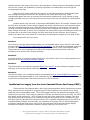
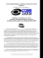
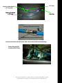
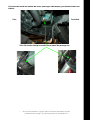
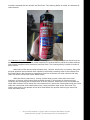
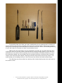
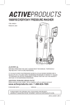
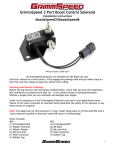
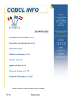
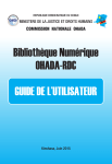
MAZDASPEED3/6 and MPS Service Bulletin
Table of Contents
Introduction................................................................................................................................................1
Suggested Servicing From the Factory......................................................................................................2
Factory Technical Service Bulletins (TSB)................................................................................................2
Which AccessPORT calibration do I install on my ECU?.........................................................................3
Which map (AKA calibration) do I choose for installation?.................................................................3
What is the difference between Stage1 and Stage2?.............................................................................3
What do all of the numbers in the map name mean?............................................................................3
What do all of these +SF, +TIH, and +IC acronyms stand for?............................................................4
What if I upgraded my turbo / air intake / Intercooler (IC) / etc?.........................................................4
Issues you will likely run into while modifying your vehicle....................................................................5
Rapidly wearing spark plugs.................................................................................................................5
Inability for the stock BOV to hold turbo boost pressure above 17-18psi............................................5
Excessive crankcase pressures due to poor Positive Crankcase Ventilation (PCV) design – Burning
oil at idle................................................................................................................................................5
Solution 1..........................................................................................................................................6
Solution 2..........................................................................................................................................6
Solution 3..........................................................................................................................................6
Solution 4..........................................................................................................................................6
Insufficient fuel supply from the stock Camshaft Driven Fuel Pump (CDFP).....................................6
Excessive carbon build up on your intake valves..................................................................................8
Failure of the stock DI fuel injector seals in high horsepower applications (350+WHP).....................9
Service Bulletin Update - Appropriate Spark Plugs.................................................................................10
Service Bulletin Update - Installing a Catch Can or Air/Oil Separator...................................................11
Service Bulletin Update - Intake Valve Cleaning....................................................................................18
What is the most beneficial upgrade path for my car?.............................................................................32
1) AccessPORT + free flowing intake system.....................................................................................32
2) CDFP upgrade + Turbo Inlet Hose (TIH).......................................................................................32
3) COBB DP or free flow exhaust system + upgraded BOV...............................................................32
4) IC upgrade + modified fueling system............................................................................................32
5) Upgraded turbo...............................................................................................................................33
6) Upgraded exhaust manifold (EXM)................................................................................................33
Introduction
This Service Bulletin has been created to help keep you informed about properly
maintaining your MAZDASPEED3/6 and MPS vehicle running the L3T DISI (Direct Injection Spark
Ignited) engines. This bulletin will also keep you informed of some engineering short-comings from
the factory that you may experience while modifying your vehicle and to keep you up-to-date with
some extended service techniques that can be used to make sure that your vehicle is performing
optimally at all times.
•
All service manual information is Copyright © 2008-2011 Information of Mazda Motor Corporation
All Other Information Copyright © 2011 Cobb Tuning Products, LLC All Rights Reserved.
Suggested Servicing From the Factory
In order for the AccessPORT to work properly on your vehicle, your vehicle must be in
proper mechanical order. The AccessPORT has been designed to allow you to reflash your factory
ECU for performance, driving quality, and fuel economy gains. Installing the AccessPORT on your
vehicle is not going to fix any mechanical problems that currently exist on your vehicle. All
scheduled maintenance procedures and some additional service recommendations must have
been performed in order for your vehicle to run properly with or without the AccessPORT installed.
We have hosted several pages from the 2008 factory Mazdaspeed3 service manual* in order to
inform you of the suggested maintenance schedule for your vehicle:
Suggested Maintenance Schedule for Normal Driving Conditions (Average or Normal Conditions)
Suggested Maintenance Schedule for Unique Driving Conditions (Severe, Extreme, or Adverse
Conditions)
General Diagnostic Information
Factory Technical Service Bulletins (TSB)
We have also hosted various documents (Technical Service Bulletins [TSB] & Recalls) that
Mazda has released in order to inform Mazdaspeed3/6 vehicle owners of various updates or
defective parts that need to be replaced. The list of the more critical documents is below:
TSB 01-002-08 – VARIABLE VALVE TIMING (VVT) NOISE WHEN STARTING ENGINE
TSB 01-002-11 – WHITE OR BLUE SMOKE FROM TAIL PIPE AFTER LONG IDLE PERIOD
TSB 01-010/07 - DTC P2006 (VARIABLE SWIRL CONTROL SYSTEM SHUTTER VALVE STUCK CLOSED)
TSB 01-022/06 – FRONT CRANKSHAFT BOLT SERVICE WARNING
TSB 01-022/08 - DTC P2177/P2187 (FUEL SYSTEM LEAN) Deficient Camshaft Driven Fuel Pump
(CDFP)
TSB 01-037/06 - MIL COMES ON WITH DTC P2407 (LDP SENSOR ERRATIC)
TSB 03-001-08 – MS6 OIL SEEPAGE FROM TRANSFER CASETSB 09-004/08 - TCS / DSC WARNING
LIGHT ON WITH DTC C1956
Recall 4607F (Owner Letter) - 2007 MAZDASPEED3 Engine Mount Safety Recall 4607F
Information concerning the vehicles affected, symptoms, diagnosis, and corrective
procedures is within these documents. If your vehicle falls within the boundaries of these
documents or is exhibiting abnormal behavior, we highly suggest you have your vehicle serviced
by a certified Mazda service center as soon as possible. These mechanical problems will need to
be properly repaired before you will be able to operate your vehicle with any AccessPORT
calibration. We suggest you do not modify your vehicle until you have the vehicle in proper
working order.
This document was not created to give our impressions of Mazda's build quality. We simply
put this together in order educate Mazdaspeed3/6 & MPS owners of various known issues that may
exist on their vehicle. Mazda is a very high quality manufacturer that produces excellent quality
vehicles.
•
All service manual information is Copyright © 2008-2011 Information of Mazda Motor Corporation
All Other Information Copyright © 2011 Cobb Tuning Products, LLC All Rights Reserved.
Which AccessPORT calibration do I install on my ECU?
Brought to you by Braden Bergher of
If you have any difficulties installing your AccessPORTTM please contact the Cobb Tuning authorized
dealer you purchased the device from.
Which map (AKA calibration) do I choose for installation?
●
Map or calibration files are named according to the modifications they support and the type of
fuel being used. Some map or calibration files name examples are Stage1 91 v200, Stage1+SF
91 v200, or Stage1+SF+TIH+IC 93 v200.
What is the difference between Stage1 and Stage2?
●
●
Stage1 is for use on stock vehicles or vehicles with only a supported intake system and/or a
cat-back exhaust.
Stage2 is for use on vehicles with a full turbo-back exhaust (cat-back and turbo downpipe)
that has a high-flow catalytic converter installed.*
*Stage 2 can also be used on vehicles with an aftermarket downpipe or test pipe, and stock catback exhaust, but it will not perform as well as a full turbo-back vehicle.
●
The following modifications are compatible with both Stage1 and Stage2:
- Lightweight flywheel and performance clutch.
- Drop-in (stock replacement) high flow air filter
- One step colder spark plugs (Denso ITV22 gapped to 0.025 recommended)
What do all of the numbers in the map name mean?
●
●
●
●
These describe the fuel quality that the map is calibrated for. Calibrations for fuels other
than 91/93 octane are still under development.
91 = Can be used on 91 or 92 octane pump gas.
93 = Can be used on 93 or 94 octane pump gas.
ACN = Can be used on Arizona, California & Nevada 91 or 92 octane pump gas.
•
All service manual information is Copyright © 2008-2011 Information of Mazda Motor Corporation
All Other Information Copyright © 2011 Cobb Tuning Products, LLC All Rights Reserved.
●
●
The “v2XX” number is the revision of the calibration, the higher the number, the newer the
calibration. We recommend you install the most current calibration.
All calibrations are compatible with Ethanol mixtures up to 10% (E10) and are not
compatible with blends of E85.
What do all of these +SF, +TIH, and +IC acronyms stand for?
●
●
●
●
●
●
●
●
●
●
●
●
●
●
+SF = Specifies the calibration was designed for and requires the Cobb Tuning SF intake
system to be installed in order for the calibration to operate properly.
+cpCAI = Specifies the calibration was designed for and requires the cp-E Cold Air Intake
system to be installed in order for the calibration to operate properly.
+cpN = Specifies the calibration was designed and is required to be used with a cp-E Nano
intake system installed.
+CS = Specifies the calibration was designed and is required to be used with a Corksport
SRI intake system installed.
+FUCAI = Specifies the calibration was designed and is required to be used with a Fujita
Cold Air Intake system installed.
+HKS = Specifies the calibration was designed and is required to be used with a HKS intake
system installed.
+INCAI = Specifies the calibration was designed and is required to be used with an Injen
Cold Air Intake system installed.
+KNSRI = Specifies the calibration was designed and is required to be used with a K&N SRI
intake system installed.
+MSCAI = Specifies the calibration was designed and is required to be used with a
Mazdaspeed Cold Air Intake without air straighteners installed.
+MSCAI2 = Specifies the calibration was designed and is required to be used with a
Mazdaspeed Cold Air Intake with air straighteners installed.*
+SUR = Specifies the calibration was designed and is required to be used with a SURE
Aeros v1 intake system installed.
+SUR2 = Specifies the calibration was designed and is required to be used with a SURE
Aeros v2 intake system installed.
+TIH = Specifies the calibration was designed and is required to be used with an
aftermarket Turbo Inlet Hose installed.
+IC = Specifies the calibration was designed and is required to be used with an aftermarket
intercooler installed (TMIC or FMIC).
*Please note that the MSCAI2 calibration can also be used with an AEM Cold Air Intake system.
Some intake calibrations may not be available for your model or year of vehicle.
Please check the map notes for boost targets as these change per vehicle and map.
What if I upgraded my turbo / air intake / Intercooler (IC) / etc?
●
●
Please check the AccessPORT map download section to see if a calibration is available for
your specific configuration. We will have calibrations available for many common upgrades
beyond the standard staged maps.
If a map is not available for your specific configuration, you will want to consult with an
authorized AccessTUNER in your area for custom calibration for your vehicle.
•
All service manual information is Copyright © 2008-2011 Information of Mazda Motor Corporation
All Other Information Copyright © 2011 Cobb Tuning Products, LLC All Rights Reserved.
COBB TUNING
TM
Issues you will likely run into while modifying your vehicle.
This section has been put together to help explain what mechanical issues you may run
into as you continue to modify your vehicle from stock. The stock components were designed with
specific applications in mind. When you increase the power output, efficiency, and other functional
aspects of the engine several stock components will no longer be up to the job of supporting the
increased power output.
Rapidly wearing spark plugs.
Most DISI engines have special piston designs that direct the incoming air and fuel charge
towards the spark plug for a more complete combustion. We've found that this and other DISI
features wear spark plugs more rapidly than a normal port-injected engines would. Depending on
the level of performance modifications, the standard port-injection engine would be able to run the
same spark plug set for around 15,000-50,000 miles. Although, with the L3T DISI engine, we've
found that this engine wears spark plugs more rapidly. You should budget on changing the L3T
spark plugs at shorter intervals, something along the 5,000-15,000 mile rage.
A wearing spark plug initially exhibits higher boost miss-fires, poor power production, or
stumbles under WOT conditions. If you then run a calibration that runs lower boost and the missfires go away, this is an indication of wearing plugs. Some very worn plugs will also create idle and
part-throttle miss-fires on various cylinders which the ECU may detect and then report as a
recorded miss-fire. The first Service Bulletin Update will give you the information you need to order
the correct replacement spark plugs.
Inability for the stock BOV to hold turbo boost pressure above 17-18psi.
The L3T DISI engine has a turbocharger that is capable of safely generating more boost
pressure once the supporting Stage2+ modifications have been added to the car. Although, we've
found that the stock BOV cannot hold the increased turbo boost pressures above 17-18psi. Around
these pressure levels the stock BOV (or By-Pass Valve [BPV]) simply opens and allows the charged
air to recirculate back into the intake. This BOV leak pushes the turbo to work much harder to recompress the purging intake charge.
If you plan on running over 17psi of boost pressure on a Stage1 or Stage2+ hardware
combination or if you are running an after market turbo, we highly suggest that you replace the
stock BOV with an quality aftermarket one like the COBB XLE BPV.
Excessive crankcase pressures due to poor Positive Crankcase Ventilation
(PCV) design – Burning oil at idle.
Some L3T DISI engines (in completely stock form) burn oil through the engine and oil smoke
pours from the tailpipe while at idle. This is due to several issues that we've found with this
platform. First, the PCV source where the crankcase pressures are pulled (or sucked) comes from
the engine block itself, not from the head or valve cover as is on almost all other vehicles. Pulling
the crankcase ventilation from the top of the engine assembly, rather than the lower crankcase
assembly as is done on the Mazda L3T DISI engine, is done to avoid pulling in atomized, liquid oil,
or further contaminated crankcase gases from the crankcase housing. The crankshaft is spinning
through pressurized, hot engine oil at several hundred RPM while at idle and mixes combustion
•
All service manual information is Copyright © 2008-2011 Information of Mazda Motor Corporation
All Other Information Copyright © 2011 Cobb Tuning Products, LLC All Rights Reserved.
chamber blow-by and engine oil into the crankcase gases. If these gases are immediately sucked
into the PCV system, the probability of having significant oil contamination sent through the
running engine are high.
When the PCV system pulls from this source, it can then send these contaminated gases
back through the engine via the PCV exit located on the Turbo Inlet Hose (TIH). These
contaminated gases are then run through the combustion chamber and if oil is present in large
enough quantities, then you will visibly see the burned oil come out the tailpipe as a whitish/blue
smoke.
Another reason why the stock 1st Generation MS3/6/MPS (Gen1) PCV design is flawed is that
the PCV valve and rubber hoses can get clogged with these contaminants in the crankcase gases.
The valve and plumbing then won't allow the crankcase pressure to vent properly. This ends up
creating excessive crankcase pressures which blocks off or impedes the oil return line from the
turbo charger. Once this oil return line is impeded, the pressurized engine oil feeding the turbo has
no where else to go other than through the turbo shaft seal into the relatively lower pressure
intake tract when even more liquid oil is eventually sent through the engine to burn while at idle.
Four solutions for this issue exist:
Solution 1
You can have a service update performed by your local Mazda dealer if your vehicle is still under
warranty. With this TSB service update from the dealership, you will receive a new valve cover and
a newer TIH which match the current design on the 2nd Generation (Gen2) MAZDASPEED3/MPS.
These new pieces have implemented a better PCV design and pull the positive crankcase
ventilation from the top of the engine assembly.
Solution 2
A second solution is to install a better flowing PCV valve and oil catch can or air/oil separator as is
described in our second Service Bulletin Update.
Solution 3
The third solution is to install an upgraded Gen1 TIH or Gen2 TIH which allows the engine to more
efficiently suck out the positive crankcase pressures.
Solution 4
The fourth solution can be implemented by downloading the free AccessTUNER Race software and
increasing the idle speed targets on your calibration by approximately 100 RPM to allow the engine
to pull more of the positive crankcase pressure out of the crankcase.
Insufficient fuel supply from the stock Camshaft Driven Fuel Pump (CDFP).
These vehicles are equipped with a ultra high pressure gasoline direct injection fuel system.
Many components are involved in compressing your Direct Injection Fuel Pressure (DIFP) into a
superfine mist of combustible magic. The journey begins with the low pressure fuel pump (LPFP)
inside of your fuel tank. This pump runs between 53-61psi and delivers fuel to the CDFP. The CDFP
then steps up the pressure to ~1650-1700psi on the way to the combustion chamber. This ultra
high pressurized fuel is sprayed in an extremely fine mist and ignited by your combustion cycle
and spark ignition. We have found that the stock LPFP is capable of delivering fuel to the CDFP up
to approximately 330whp. Unfortunately, the capability of the stock CDFP is vehicle dependent.
Our testing has shown that nearly every Gen2 and most Gen1 MS3 vehicles running Stage2
hardware and Stage2 calibrations exceed the fueling capacity of the stock CDFP.
•
All service manual information is Copyright © 2008-2011 Information of Mazda Motor Corporation
All Other Information Copyright © 2011 Cobb Tuning Products, LLC All Rights Reserved.
We've created Safe Mode calibrations for Mazdaspeed3 vehicles that will limit the
achievable boost levels in order to keep the fueling demands within the fueling capacity of the
stock CDFP. For those with Stage2 hardware whom are not looking to push the power output of
your engine, these Safe Mode calibrations are your best choice in order to keep the fueling
demands within the capacity of the stock CDFP. Please note that we have not seen these types of
CDFP issues on the Mazdaspeed6 and as such have not created Safe Mode calibrations for this
vehicle.
Due to the nature of the inadequacies and inconsistencies of the factory CDFP we have
designed our OTS calibrations around the following observations; the Gen2 MAZDASPEED/MPS ECU
has logic implemented that will significantly increase fueling to the engine once the DI Fuel
Pressure drops below ~1600psi. This logic is intelligent by design, but also puts excessive
demands on the fueling system and further forces the DI Fuel Pressure to drop well below safe or
effective levels. This new logic combined with an inadequate factory Camshaft Driven Fuel Pump
(CDFP) results in the following.
•
•
ALL Stage1 OTS Calibrations have been designed to run within the limits of the factory
CDFP to remain safe. Even at this power level, some vehicles may exceed the capacity of
the factory CDFP. We recommend that you run a "Safe Mode" calibration on the vehicle until
a quality aftermarket CDFP can be installed.
ALL Stage2 OTS Calibrations REQUIRE a quality aftermarket CDFP to run properly. If you
have Stage2 hardware on your vehicle and have not installed a quality aftermarket CDFP, it
is highly recommended to run a "Safe Mode" calibration on the vehicle until a quality
aftermarket CDFP can be installed.
Below is an example of a datalog where one can see the stock CDFP failing during a Wide
Open Throttle (WOT) run in 3rd gear. If this see this behavior with your vehicle, please switch to a
Safe Mode calibration or cease running the vehicle hard until the CDFP can be upgraded.
As you can see, the driver is holding the throttle down during a WOT 3rd gear run and the
DIFP starts dropping off from its target of ~1650psi (at row 47) all the way down to ~700psi. This
is an indicator that your current CDFP is not capable of keeping up with fueling demands.
•
All service manual information is Copyright © 2008-2011 Information of Mazda Motor Corporation
All Other Information Copyright © 2011 Cobb Tuning Products, LLC All Rights Reserved.
2000
100
1800
90
1600
80
1400
70
1200
60
1000
50
800
40
600
30
400
20
200
10
0
17
50
18
39
20
47
23
00
25
73
29
40
33
33
38
11
42
25
45
81
49
57
Throttle/Boost
DIFP
Stock CDFP Failure
Throttle Position (%)
DI Fuel Press. (PSI)
Boost (PSI)
0
RPM
The above graph is from the same datalog. Boost builds and holds steady at around 17psi
across the RPM range, but starting at 3000 RPM, the DIFP starts to drop off, then continues to drop
off severely enough that the ECU steps in and closes the throttle (lowering boost) to help limit
torque production...and thus fueling demand. Once boost drops a few psi, the CDFP is capable of
building enough pressure to achieve the DIFP targets and the ECU then allows the throttle to open
fully once again.
Using AccessTUNER Race, you have a two strategies that can be employed (individually or
combined) in order to work around this issue until an upgraded CDFP is installed.
1) You can incrementally lean our your WOT fueling targets to reduce fueling demands. This
may not be possible with some lower fuel qualities since it may cause to lean (hot) of a
combustion and Knock Retard values can increase when this happens.
2) You can incrementally decrease your WOT boost (or load) targets until you have the engine
producing less torque, reducing fueling demands.
Excessive carbon build up on your intake valves.
DISI engines are unique in that the fuel injector sprays directly into the combustion
chamber and not on top of the intake valve from the intake port/runner (as is done with a portinjection engine). With a port-injection engine, the fuel injector actually keeps the intake valves
relatively clean by spraying fuel (a solvent) directly onto the intake valves. This constant spraying
constantly cleans carbon and other deposits from the valves.
Without fuel being sprayed directly onto the intake valves, excessive deposits are allowed
to form. These deposits can build to an inch or more in diameter near the head of the valve. This
excess build up can cause the following issues:
–
–
Poor or erratic idle
Cylinder or engine miss-fires
•
All service manual information is Copyright © 2008-2011 Information of Mazda Motor Corporation
All Other Information Copyright © 2011 Cobb Tuning Products, LLC All Rights Reserved.
–
–
–
Poor fuel economy
Excessive valve train wear &
Poor power production
We've documented a cleaning process that you can use to help keep your engine running
optimally. Depending on various factors including intake filter efficiency, quality of engine oil and
fuel used, duration of time/mileage between engine oil changes, cleanliness of the PCV and EGR
system, etc. the intake valves on the L3T DISI engines can generate excessive build up as soon as
10,000 miles. We suggest that you incrementally inspect and clean your intake valves at an
interval that allows your engine to continue to run properly.
Failure of the stock DI fuel injector seals in high horsepower applications
(350+WHP).
The L3T DISI engine employs direct injection fuel injectors that are mounted in the head
and spray fuel directly into the combustion chamber. These injectors are held in place by a bracket
and torx bolt (please be careful to not strip this bolt) so they do not pop out under the extreme
compression/combustion pressures. Each injector seats against an injector seal located at the
bottom of the injector, deep within the head.
With each combustion cycle, these injectors are pushed up or compressed against the
bracket and then seat back down on the seals and with time, the stock injector seals can become
compressed allowing the DI fuel injector to rattle within the injector hole. The extreme heat being
located so close to the combustion chamber also makes the stock injector seals brittle with time.
This rattle is some times picked up by the engine's knock sensor and can be calculated as a knock
event by the ECU. This is also known as false knock since the knock sensor is essentially a
microphone designed to listen for noises within the frequency range of engine detonation or
knock. The engine may not be detonating, but the DI fuel injector rattle can cause false knock
which disallows the engine from running properly.
If you notice that your ECU is suddenly picking up more Knock Retard (KR) than normal, and
you have ruled out all other common reasons for this (poor quality of fuel from your last fill up,
excessive ambient heat, heat soak, rattling heat shield, etc.), then you may need to remove your
DI fuel injectors in order to replace the DI injector seals located within the head. One good test for
•
All service manual information is Copyright © 2008-2011 Information of Mazda Motor Corporation
All Other Information Copyright © 2011 Cobb Tuning Products, LLC All Rights Reserved.
false knock is to fill your fuel tank with 2-4 gallons of higher octane unleaded race fuel, around 100
octane will suffice. If the KR is still present, it's likely that your current DI fuel injector seals are
failing or have failed. Several manufacturers offer after market alloy injector seals that are better
suited for the higher temperatures and cylinder pressures realized by higher horsepower
MAZDASPEEDs. If you plan on generating more than 350WHP or you notice a sudden change in
your Knock Retard response, you may need to replace the stock DI injector seals. You can simply
type “mazdaspeed injector seals” into your preferred web search engine and several options are
available to you.
Service Bulletin Update - Appropriate Spark Plugs
Our data has shown that the factory spark plug temperature range (6) and gap (~.034”)
are sufficient for stock boost levels and normal driving conditions. Although, operating the car with
higher than stock boost levels or with the calibrations that are loaded on the AccessPORT, require
that a spark plug gap of .026” - .028” (6.6 – 7.1mm) be used on a 1-step colder temperature plug.
Denso currently offers this spark plug as part # ITV22 (please be sure to verify each plug is
properly gaped before installing them). Our experience has shown that operating your turbocharged engine at higher than stock boost levels requires that your spark plugs be replaced at
around 12,000-15,000 mile intervals.
•
All service manual information is Copyright © 2008-2011 Information of Mazda Motor Corporation
All Other Information Copyright © 2011 Cobb Tuning Products, LLC All Rights Reserved.
Service Bulletin Update - Installing a Catch Can or Air/Oil
Separator
Brought to you by Tim Bailey of
Installing an oil catch can or air/oil
separator and upgraded Positive Crankcase
Ventilation (PCV) system in the Mazdaspeed3/6 & MPS
Turbocharged engines often develop positive pressure inside the crankcase because
combustion pressure escapes past the piston rings separating the combustion chamber from the
crankcase. This crankcase pressure has a detrimental effect on power production, turbo oil
drainage, and overall pumping efficiency of the engine. While vacuum is present in the intake
manifold, this crankcase pressure is relieved through a high strength tube that connects the
crankcase to the intake manifold. This high strength tube connects to the intake manifold at a ONE
way valve called a PCV or positive crankcase pressure ventilation valve. The function of this valve
it to prevent positive manifold pressure from entering the crankcase or to pull any positive
pressure out of the crankcase.
The Mazdaspeed3/6 engines contains a PCV valve. However, the stock PCV valve and
associated lines does a poor job of venting positive crankcase pressure without also contaminating
the intake manifold with oil and combustion gases from the crankcase, as well as slowing down the
oil draining from the turbo's center cartridge bearings. The contaminant oil and crankcase gases
lower the detonation threshold when ingested in the combustion cycle. This can lead to oil burning
through the exhaust stream, decreased engine efficiency, and eventual engine damage.
This document outlines the installation of an additional PCV valve and, importantly, an oil
catch can or air/oil separator system for a Mazdaspeed3/6. We first recommend that you inspect
and clean your stock PCV valve, or even replace it if it is full of carbon/crankcase deposits and no
longer functions properly. These instructions include information on a more durable PCV valve that
can be used to replace the stock PCV valve or that can work in conjunction with it (although, the
PCV system will only work properly if botch PCV valves are not jammed up with contaminants).
With a system similar to this in place, much less oil from the crank case contaminates the
intake tract. In fact, the installation of an additional PCV valve and oil catch can or air/oil separator
will often totally remedy Mazdaspeed3/6's persistent oil burning issues.
•
All service manual information is Copyright © 2008-2011 Information of Mazda Motor Corporation
All Other Information Copyright © 2011 Cobb Tuning Products, LLC All Rights Reserved.
The system consists of the following items:
1. Approximately 6 feet of vacuum resistant 5/8 inch ID tubing. This tubing must be reinforced
so as to resist high vacuum. Some forms of tubing will collapse under vacuum and will
make this system totally ineffective. Make sure to specify vacuum resistant tubing.
2. A secondary PCV valve. We used NAPA part number 2-9303.
3. A catch can and mounting bracket – Any manufacturer can be substituted with reasonable
results.
Installation:
1) Be sure to set your emergency brake, carefully lift the front of the vehicle onto jack
stands, and remove the plastic under tray to allow access to the front of the engine and
intake manifold.
Remove the plastic under tray
2) Locate the tube connecting the intake manifold to the crankcase. Carefully remove this
tube from the intake manifold.
Tubing to crankcase
3) Assemble the catch can and PCV system components:
•
All service manual information is Copyright © 2008-2011 Information of Mazda Motor Corporation
All Other Information Copyright © 2011 Cobb Tuning Products, LLC All Rights Reserved.
Fitting to intake
manifold
PCV Valve
Attach to Intake Manifold
(~39” long total)
Attach to Crankcase
(~36” long)
Catch Can
Close up of PCV valve from above
Closed
Closed under
under boost
boost and
and open
open under
under vacuum
vacuum
4) Attach the tube with the in-line PCV valve to the intake manifold fitting.
Attach tubing with PCV
to intake manifold fitting
•
All service manual information is Copyright © 2008-2011 Information of Mazda Motor Corporation
All Other Information Copyright © 2011 Cobb Tuning Products, LLC All Rights Reserved.
5) Using a hose clamp, secure the 5/8 barbed adapter to the stock tube which has been
removed from the intake manifold.
Attach 5/8 barb straight
fitting to the stock tubing
removed from the intake
manifold
6) Attach the longer section of tube, without the PCV valve, to the straight barb fitting.
Attach long end of tuning without
PCV to the barb fitting
•
All service manual information is Copyright © 2008-2011 Information of Mazda Motor Corporation
All Other Information Copyright © 2011 Cobb Tuning Products, LLC All Rights Reserved.
7) Locate the catch can behind the lower passenger side bumper, just ahead of the front
wheels.
Front
Front wheel
Catch Can location looking from under the car toward the passenger tire
•
All service manual information is Copyright © 2008-2011 Information of Mazda Motor Corporation
All Other Information Copyright © 2011 Cobb Tuning Products, LLC All Rights Reserved.
8) Secure lines between catch can, intake manifold, and crank case so they do not rub and
wear against any of the undercarriage.
Front wheel
Front
Catch Can location just in front of the passenger tire behind the bumper
9) Reinstall the plastic under tray.
The improved PCV system will help remove pressurized air from entering the crankcase and
help prevent oil contaminated air from entering the inlet air stream. The crankcase will now
properly ventilate only under vacuum. With a external oil catch can or air/oil separator in place,
less oil will enter the inlet air stream which will increase the detonation threshold of the engine,
improving engine performance. This simple PVC system improvement will allow a stock or tuned
Mazdaspeed3/6s to burn less oil under idle, full boost during WOT runs, and during prolonged
periods of vacuum.
•
All service manual information is Copyright © 2008-2011 Information of Mazda Motor Corporation
All Other Information Copyright © 2011 Cobb Tuning Products, LLC All Rights Reserved.
Service Bulletin Update - Intake Valve Cleaning
Brought to you by Evan Goldberg of
This update is a brief summary explaining how to clean the intake valves on a L3T Mazda
DISI engine. This particular engine has just over 30,000 miles on it and has used only premium
grade 93 octane fuel along with fully synthetic oil. The vehicle’s EGR was deleted at 24,000 miles.
The decision was made to clean the valves to get this motor into peak performing condition so we
could use the vehicle as a COBB Tuning test vehicle. We also wanted to test our theories to see
what role the condition of the intake valves have on the vehicle’s performance.
During initial dyno tuning, we noticed that we were unable to reach the timing levels that
are known to be attainable on other cars without seeing appreciable amounts of Knock Retard (KR)
in the datalogs. It was also noted that the car’s idle was rougher than it should be. The following
pictures were taken previous to the cleaning. These valves had not been cleaned at any point prior
to these pictures being taken.
Cylinder #4
These pictures represent cylinder #s 4-2, starting at driver's side of the car and working to
the passenger side, where the timing chain is located. Although, as you can see, the intake valves
•
All service manual information is Copyright © 2008-2011 Information of Mazda Motor Corporation
All Other Information Copyright © 2011 Cobb Tuning Products, LLC All Rights Reserved.
for the cylinder closest to the Exhaust Gas Recirculation (EGR) port, pictured above, have the
greatest amount of carbon build up. This carbon build up is more common with DISI engines since
a fuel injector is no longer located in the port, firing above the intake valves in order to help wash
the carbon off of the valves. It can be assumed that the closer in proximity to the return for the
EGR system, the greater carbon build up on the intake valves will occur.
The valves in this port were the only of the 8 individual ports on the vehicle that showed a
thick, gooey type of carbon build up as opposed to a dried/charred looking carbon build up
exhibited on the intake valves of the other three cylinders.
Cylinder #3
Less gooey carbon is present on the intake valves for this cylinder, but the carbon build up
is still significant and unexpected for such low mileage.
•
All service manual information is Copyright © 2008-2011 Information of Mazda Motor Corporation
All Other Information Copyright © 2011 Cobb Tuning Products, LLC All Rights Reserved.
Cylinder #2
Unfortunately, we managed to not capture a picture of the #1 cylinder before the cleaning.
As we mentioned, the carbon build up was less intense on the cylinders that are located further
away from the EGR return.
To clean the valves, a variety of solvents were tested. Each solvent was allowed to soak for
15 minutes inside the port before any brushing or physical cleaning took part. The following were
our impressions as to how each solvent interacted with the carbon buildup on the valves.
Ranked in Order of Effectiveness:
•
All service manual information is Copyright © 2008-2011 Information of Mazda Motor Corporation
All Other Information Copyright © 2011 Cobb Tuning Products, LLC All Rights Reserved.
I. Denatured Alcohol – Had the strongest effect on the buildup and did the best job in turning the
solution inside the port into a homogenous liquid saturated with the carbon build up. When
scrubbed and siphoned away, the alcohol performed the best at removing the most buildup each
subsequent “soak”.
•
All service manual information is Copyright © 2008-2011 Information of Mazda Motor Corporation
All Other Information Copyright © 2011 Cobb Tuning Products, LLC All Rights Reserved.
II. Sea Foam – Had a strong effect on the buildup but unlike the alcohol, did not dissolve the build
up as much as it broke it down into a removable “goop” that could be scraped away and removed
from the port. Unlike any other solution, the Sea Foam allowed me to scoop up material that would
stick to the tools.
III. Brake & Parts Cleaner – While after soaking and scrubbing, the siphoned liquid from the port
was obviously saturated with carbon material, the overall affect it had on the valve surfaces was
•
All service manual information is Copyright © 2008-2011 Information of Mazda Motor Corporation
All Other Information Copyright © 2011 Cobb Tuning Products, LLC All Rights Reserved.
minimal compared with the alcohol and Sea Foam. The cleaning ability is similar to carburetor &
choke cleaner.
IV. Carburetor & Choke Cleaner – While after soaking and scrubbing, the siphoned liquid from the
port was obviously saturated with carbon material, the overall affect it had on the valve surfaces
was minimal compared with the alcohol and Sea Foam. The cleaning ability is similar to brake &
parts cleaner.
While none of the above tested solvents were “miracle” workers by any means, along with
physical agitation these solvents were capable of eventually removing most of the buildup from
the intake valves. We are open to suggestions from the community on other solvents that may
clean the carbon on the DISI intake valves better.
While we did not capture any “during” photos taken of each valve after their initial
soakings; in the end, all the valve ports received at least 15-20 minutes of vigorous picking,
scraping, and scrubbing with a combination of all the solvents. Please be sure to not scratch the
valve shaft surfaces too far above the valve head as this is where the valves glide inside the valve
seals and a scratched valve shaft surface may cause premature wear of the valve seal. This
caution also goes for the bottom of the valve head where the precise machining to match the
valve seat takes place.
•
All service manual information is Copyright © 2008-2011 Information of Mazda Motor Corporation
All Other Information Copyright © 2011 Cobb Tuning Products, LLC All Rights Reserved.
To physically clean the valves, we used a combination of gun cleaning tools, consisting of
various picks and wire brushes to agitate and remove the carbon buildup. The pick tool comes in
handy when attempting to remove buildup on the back side of the valve. Some bending/flattening
of your tools may be necessary to better accommodate the job.
While in the end, the valves in no way resemble a new part, we can state that they were
sufficiently clean for the task at hand. We were able to remove a large majority of the hard and
soft build up on the valve surface, leaving only the most stubborn of buildup remaining. If more
time had been allotted, we are confident that the remaining buildup could have been removed.
Longer soak times and more diligent cleaning would also help remove the built up carbon. The
more soaking and scrubbing time you a lot to this job, the cleaner the intake valves will get.
The following are pictures after the cleaning, with a better lighting than what was used on
the “before” shots.
•
All service manual information is Copyright © 2008-2011 Information of Mazda Motor Corporation
All Other Information Copyright © 2011 Cobb Tuning Products, LLC All Rights Reserved.
Cylinder #1 After
Cylinder #2 After
•
All service manual information is Copyright © 2008-2011 Information of Mazda Motor Corporation
All Other Information Copyright © 2011 Cobb Tuning Products, LLC All Rights Reserved.
Cylinder #3 After
Cylinder #4 After
After the car was put back together and started, it was immediately noticeable that a
smoother idle was achieved. We also noticed that the engine was clearly breathing better due to
the +18% LTFTs that were present after the cleaning. The MAF calibration curve had already been
dialed in perfectly.
•
All service manual information is Copyright © 2008-2011 Information of Mazda Motor Corporation
All Other Information Copyright © 2011 Cobb Tuning Products, LLC All Rights Reserved.
The above dyno graph is the before and after intake valve cleaning comparisons on the
same vehicle running the exact same tuned calibration. The “before” runs (blue) were done in the
morning in approximately 90 degree temperatures. The “after” run (red) was done in the afternoon
with 100+ degree temperatures.
While the numbers may appear to be inconclusive, you can see that we’ve gained more
peak torque due to the ability for the car to reach boost targets at an earlier RPM range. The
power and torque curves appear very similar, however those levels were achieved even though
ambient air temperatures were 10-15 degrees warmer and boost levels tapered off more above
4000 RPM. The greater flowing intake valves actually run lower boost on the same Wastegate Duty
Cycle (WGDC) values. Remember, boost is a measurement of restriction, or how much air is NOT
getting into and out of the engine. The carbon build up on the intake valves was effectively
decreasing engine airflow and creating more flow restrictions on the intake side of the head.
In conclusion, we can say that the vehicle is running smoother than ever after the cleaning,
•
All service manual information is Copyright © 2008-2011 Information of Mazda Motor Corporation
All Other Information Copyright © 2011 Cobb Tuning Products, LLC All Rights Reserved.
even though these numbers cannot describe smoothness. We are now also able to run up to 18* of
timing up top where that was not possible before the cleaning. Mid and higher RPM knock events
have been clearly reduced as well.
We hope this latest service bulletin update has been helpful and we look forward to working
with the community to push these platforms even further.
What is the most beneficial upgrade path for my car?
When it comes to getting the biggest bang-for-the-buck with aftermarket performance
hardware, you need to look at the areas of flow restriction and where the MFG needed to
compromise in order to manufacture a vehicle within the allotted budget. For the MAZDASPEED,
we have found that the following steps are a safe and effective way to upgrade your vehicle in a
step-by-step process in order to build the ultimate performance sports car.
As far as the most beneficial (greatest bang-for-the-buck) upgrade path; the data is telling
us that the following is ideal for the MAZDASPEED and MPS platforms:
1) AccessPORT + free flowing intake system.
The stock ignition advance settings are a little aggressive (especially on the Gen2
platforms), the stock calibration tends to create boost spikes, runs a bit lean on spool up (a
bit lean for the DI Fuel Pressure this car runs), the throttle response is not very linear, etc.
All AccessPORT calibrations have taken into account common hardware packages and fuel
qualities that this community uses. One of our several hundred calibrations is bound to
perform well for you. We know the stock intake is very restrictive (too small of a filter and
air box for a FI application), relieving inlet restrictions helps the turbo/engine breath better
and respond quicker.
2) CDFP upgrade + Turbo Inlet Hose (TIH).
These upgrades allow slightly higher boost to be targeted (even with a Stage1 vehicle) and
allows for the fueling capacity to keep up with the fueling demands. The stock CDFP can
only keep up when 18psi, or even less boost, is targeted.
3) COBB DP or free flow exhaust system + upgraded BOV.
If replacing one stock catalytic converter with a race pipe is chosen, keeping the stock 3way catalyst is ideal and replacing only one catalyst with a test pipe and CBE will
sufficiently increase the engine's Volumetric Efficiency (VE). The increased exhaust flow will
move the detonation threshold up and creates enough VE to allow for even higher boost
targets. The stock BOV can hold well up to about 18.5psi, but not much above that and it
tends to bleed off air throughout the RPM range during pulls. You can also upgrade the CBE
exhaust when you do the downpipe installation for ideal exhaust gas pressure relief after
the turbocharger.
4) IC upgrade + modified fueling system.
The stock TMIC is the most effective top-mount configuration that we've seen to date. How
Mazda plumbs the TMIC ducting from the front of the car (high pressure area) through the
hood is very effective on the road, but the additional core size is very helpful at exchanging
heat at the higher boost levels. You can also install an upgraded FMIC, but this will slightly
increase turbo lag due to the increased volume and charge pipe length of the FMIC piping.
With a higher capacity fuel system, you will be able to further benefit from higher base DI
Fuel Pressure. With a fuel feed line that has a slightly larger orifice and with a safety relief
valve that releases above 2000psi, the fueling system capacity is increases by about 10%
(which is very helpful) and with the higher DI fuel pressure, the cooling effect of the fuel
injected is increased.
•
All service manual information is Copyright © 2008-2011 Information of Mazda Motor Corporation
All Other Information Copyright © 2011 Cobb Tuning Products, LLC All Rights Reserved.
5) Upgraded turbo.
At this point in time, the stock turbo is working at its maximum capacity and you can see
this through the WGDC values that you log through the AccessPORT. The WGDC values will
likely be at or above 90% from the mid RPM range to redline...letting you know that the
stock turbo is spinning its head off.
6) Upgraded exhaust manifold (EXM).
We suggest this after the turbo upgrade because the turbo is working it heart off and this
becomes one of the limiting flow variables at this point. This helps relieve additional
exhaust gas back pressure from the engine and rids the engine of the poor OEM EXM
design. You can upgrade the EXM before the turbo, but it will require a full re-tune of the
boost control system.
Enjoy your COBB Tuned Mazdaspeed3/6 or MPS!
V1.00
•
All service manual information is Copyright © 2008-2011 Information of Mazda Motor Corporation
All Other Information Copyright © 2011 Cobb Tuning Products, LLC All Rights Reserved.