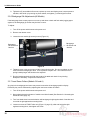
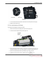
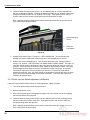
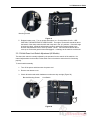
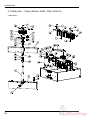
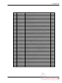
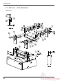
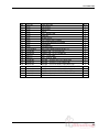
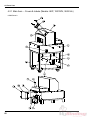
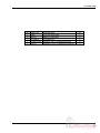
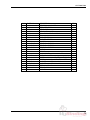
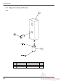
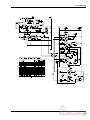
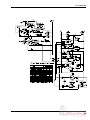
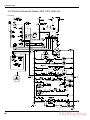
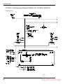
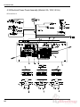
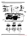
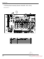
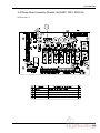
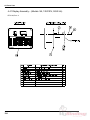
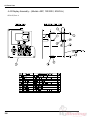
1
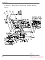
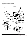
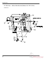
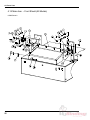
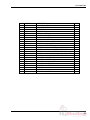
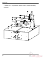
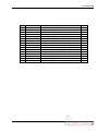
CHALLENGE
SPARTAN 185
SERVICE MANUAL
Provided By
http://www.MyBinding.com
http://www.MyBindingBlog.com
Serial Numbers 051001 & Up
TECHNICAL SERVICE
AND PARTS MANUAL
SPARTAN 185 SA/A/AEP
AUTOMATIC
PAPER CUTTER
Sold and Serviced by
The Challenge Machinery Company
6125 Norton Center Drive
Norton Shores, MI. 49441
www.challengemachinery.com
F.185-T
Jul. 2006
1.0 Introduction
NOTES
Challenge® is a registered trademark of The Challenge Machinery Company•
6125 Norton Center Drive • Norton Shores, MI 49441-6081
Copyright© 2006 by The Challenge Machinery Company. All rights reserved. Printed in the U.S.A
2
1.0 Introduction
1.0 Introduction
THIS MANUAL is designed to help you get the most from your Challenge equipment. Keep this
manual in a safe, convenient place for quick reference by operators and service personnel.
SAFETY ALERT! This symbol means CAUTION: Personal safety
instructions! Pay special attention to the instructions in bold type. Personal injury may result if the
precautions are not read and followed.
FOR PARTS AND SERVICE contact the Authorized Challenge Dealer from whom you purchased
your machine. Use the illustrations and parts lists at the back of this manual to identify the correct
parts needed. Always give the SERIAL NUMBER and MODEL of your machine to insure the correct
parts are sent as soon as possible.
3
1.0 Introduction
TABLE OF CONTENTS
1.0 Introduction ....................................................................................................................................... 3
2.0 Safety................................................................................................................................................ 6
2.1 Precautions .................................................................................................................................. 6
2.2 Power Lockout Procedure ............................................................................................................ 6
2.3 Warning Label Definitions ............................................................................................................ 7
3.0 Maintenance Guide........................................................................................................................... 9
3.1 Routine Maintenance (All Models) ............................................................................................. 10
3.1.1 Weekly ................................................................................................................................ 10
3.1.2 Monthly................................................................................................................................ 10
3.1.3 Yearly .................................................................................................................................. 10
3.2 Cleaning (All Models) ................................................................................................................. 10
3.2.1 Table ................................................................................................................................... 10
3.2.2 Display Panel ...................................................................................................................... 10
3.2.3 Machine Exterior ................................................................................................................. 11
3.3 Lubrication (All Models).............................................................................................................. 11
3.3.1 Clamp.................................................................................................................................. 11
3.3.2 Backgauge Lead Screw and Guide Shaft........................................................................... 11
3.4 Accessing the Electrical Panel (All Models) ............................................................................... 12
3.5 Adjustments................................................................................................................................ 13
3.5.1 Squaring the Backgauge (All Models) ................................................................................ 13
3.5.2 Backgauge Accuracy Adjustment (Models: SA and A)....................................................... 14
3.5.3 Backgauge Accuracy Adjustment (Models: AEP)............................................................... 16
3.5.4 Knife Bar Gib Adjustments (All Models).............................................................................. 16
3.5.5 Knife Leveling Adjustment (All Models) .............................................................................. 16
3.5.6 Backgauge Gib Adjustments (All Models) .......................................................................... 18
3.5.7 Lead Screw Collars (Models: SA and A) ............................................................................ 18
3.5.8 Line Light Adjustment (All Models) ..................................................................................... 19
3.5.9 Front Guard Switch Adjustment (All Models)...................................................................... 20
3.5.10 Knife/Clamp Sequence Adjustment (Models: A and AEP) ............................................... 20
3.5.11 Clamp-Up Limit Switch Adjustment (Models: A and AEP)................................................ 21
3.5.12 Knife-Up Limit Switch Adjustment (All Models) ................................................................ 22
3.5.13 Knife-Down Limit Switch Adjustment (All Models) ............................................................ 23
3.5.14 Re-engaging the Knife Pull-Down Gear (All Models) ....................................................... 24
3.6 Troubleshooting.......................................................................................................................... 26
4.0 Parts Lists ....................................................................................................................................... 28
4.1 Main Asm. – Backgauge Drive (Models: SA, 120/230V, 50/60 Hz) ........................................... 28
4.2 Main Asm. – Backgauge Drive (Models: A, 120/230V, 50/60 Hz) ............................................. 30
4.3 Main Asm. – Backgauge Drive (Models: AEP, 120/230V, 50/60 Hz) ........................................ 32
4.4 Main Asm. – Knife Drive (All Models)......................................................................................... 34
4.5 Main Asm. – Bottom Side Electrical (Models: SA, 120V, 60 Hz) ............................................... 36
4.6 Main Asm. – Bottom Side Electrical (Models: A/AEP, 120V, 60 Hz) ......................................... 38
4.7 Main Asm. – Bottom Side Electrical (Models: SA, 230V, 60 Hz) ............................................... 40
4.8 Main Asm. – Bottom Side Electrical (Models: A/AEP, 230V, 60 Hz) ......................................... 42
4.9 Main Asm. – Bottom Side Electrical (Models: SA, 230V, 50 Hz) ............................................... 44
4.10 Main Asm. – Bottom Side Electrical (Models: A/AEP, 230V, 50 Hz) ....................................... 46
4.11 Main Asm. – Clamp (Models: SA, 120/230V, 50/60 Hz) .......................................................... 48
4.12 Main Asm. – Clamp (Models: A/AEP, 120V, 60 Hz) ................................................................ 50
4.13 Main Asm. – Clamp (Models: A/AEP, 230V, 50/60 Hz) ........................................................... 52
4.14 Main Asm. – Knife (All Models) ................................................................................................ 54
4.15 Main Asm. – Front Shield (All Models)..................................................................................... 56
4.16 Main Asm. – Backgauge (All Models) ...................................................................................... 58
4.17 Main Asm. – Top Side Elec. (Models: SA, 120/230V, 50/60 Hz) ............................................. 60
4.18 Main Asm. – Top Side Elec. (Models: A/AEP, 120/230V, 50/60 Hz) ....................................... 62
4.19 Main Asm. – Covers and Labels (Models: SA, 120/230V, 50/60 Hz) ...................................... 64
4
1.0 Introduction
4.20 Main Asm. – Covers and Labels (Models: A, 120/230V, 50/60 Hz) .........................................66
4.21 Main Asm. – Covers & Labels (Models: AEP, 120/230V, 50/60 Hz) ........................................68
4.22 Main Asm. – Accessories (All Models) .....................................................................................70
4.23 Motor and Gearbox Assembly (All Models) ..............................................................................72
4.24 Magnet Assembly (All Models) .................................................................................................74
4.25 Floor Stand Assembly (All Models) ..........................................................................................75
4.26 Electrical Schematic (Models: SA, 120V, 60 Hz)......................................................................76
4.27 Electrical Schematic (Models: SA, 230V, 50/60 Hz) ................................................................78
4.28 Electrical Schematic (Models: A, 120V, 60 Hz) ........................................................................80
4.29 Electrical Schematic (Models: A, 230V, 50/60 Hz) ...................................................................82
Electrical Schematic (Models: AEP, 120V, 60 Hz) ...........................................................................84
4.30 Electrical Schematic (Models: AEP, 230V, 50/60 Hz) ..............................................................86
4.31 Elec. Interconnection Diagram (Models: SA, 120/230V, 50/60 Hz) .........................................88
4.32 Elec. Interconnection Diagram (Models: A, 120/230V, 50/60 Hz) ............................................90
4.33 Elec. Interconnection Diagram (Models: AEP, 120/230V, 50/60 Hz) .......................................92
4.34 Electrical Power Panel Assembly (Models: SA, 120V, 60 Hz) .................................................94
4.35 Electrical Power Panel Assembly (Models: SA, 230V, 50/60 Hz) ............................................96
4.36 Electrical Power Panel Assembly (Models: A/AEP, 120V, 60 Hz) ...........................................98
4.37 Electrical Power Panel Assembly (Models: A/AEP, 230V, 50/60 Hz) ....................................100
4.38 Relay Board Assembly (Models: SA/A/AEP, 120V, 60 Hz)....................................................102
4.39 Relay Board Assembly (Models: SA/A/AEP, 230V, 50/60 Hz)...............................................103
4.40 Display Assembly – (Models: SA, 120/230V, 50/60 Hz) ........................................................104
4.41 Display Assembly – (Models: A, 120/230V, 50/60 Hz)...........................................................105
4.42 Display Assembly – (Models: AEP, 120/230V, 50/60 Hz) ......................................................106
5
2.0 Safety
2.0 Safety
2.1 Precautions
•
•
•
•
•
•
•
•
•
•
•
•
•
•
•
•
This machine is designed for one-person operation. Never operate the machine with more than
one person.
Safe use of this machine is the responsibility of the operator. Use good judgment and common
sense when working with and around this machine.
Read and understand all instructions thoroughly before using the machine. If questions remain,
contact the dealer from which you purchased this machine. Failure to understand the operating
instructions may result in personal injury.
Only trained and authorized people should operate this machine.
DO NOT ALTER SAFETY GUARDS OR DEVICES. They are for your protection. Severe
personal injury may result.
Disconnect power before cleaning or performing maintenance. See Section 2.2 Power Lockout
Procedure.
Observe all caution labels on this machine.
Be sure the cutter is properly grounded.
Be sure there is sufficient power to operate the cutter properly.
Observe all caution plates mounted on this cutter.
Keep foreign objects off table and away from cutter blade.
BE EXTREMELY CAREFUL when handling and changing the cutter knife. Severe lacerations or
dismemberment could result from careless handling procedures.
Keep the floor around the cutter free of trim, debris, oil and grease.
When replacing hydraulic parts, loosen the connections slowly to release pressure. Never loosen
connections with the machine running.
If the cutter sounds or operates unusually, have it checked by a qualified service person.
CRUSH HAZARD, keep hand and fingers from under the clamp when clamping paper. Use
Jogging Aid to load paper, and use the backgauge to push paper out before unloading. DO NOT
REACH UNDER THE KNIFE AND CLAMP AREA!
2.2 Power Lockout Procedure
For maximum safety while making adjustments or repairs to your machine, be sure to disconnect
power to the machine. Disconnect the power plug from its socket
Figure 1 - Main Power Disconnect
6
2.0 Safety
2.3 Warning Label Definitions
The following warning labels are found at various locations on your machine. Read and understand
the meaning of each symbol. If a label is lost from the machine, it should be replaced.
HAZARDOUS AREA
Disconnect power before cleaning, servicing, or making adjustments not requiring
power. Do not alter safety guards or devices; they are for your protection. Replace
all guards. Do not operate with any guards removed.
SHOCK HAZARD
Disconnect power before removing cover. Replace cover before operation.
SHOCK HAZARD
Disconnect power before removing cover. Replace cover before operation.
SINGLE OPERATOR
Do not operate with more than one person.
7
2.0 Safety
!OJO!
This Este simbolo de alerta de seguridad significa ¡ OJO ! INSTRUCCIONES DE SEGURIDADPERSONAL. Lea las instrucciones porque se refieren a su
seguridad personal. Fall de obedecer las instrucciones que siguen podria resultar en lesiones
corporales.
•
•
•
•
•
•
•
•
•
•
•
•
•
•
•
•
•
•
•
•
Esta maquina, junto con sus mecanismos de seguridad, esta disenada para ser manejada por
UNA SOLA PERSONA a la vez. Jamas debe ser manejada por mas de una persona al mismo
tiempo.
La seguridad es la responsabilidad del operario que usa esta maquina.
LEA DETENIDAMENTE el manual de instrucciones y las PRECAUCIONES DE SEGURIDAD
antes de poner a funcionar la cortadora. Pidale a su supervisor una copia.
El manejo de la guillotina debe estar exclusivamente a cargo de personal entrenado y autorizado
para ello.
NO MODIFIQUE LOS MECANISMOS DE SEGURIDAD, estan ahi para su proteccion no deben
ni modificarse ni quitarse.
DESCONECTE LA CORRIENTE ELECTRICA antes de proceder a hacerle servicio de limpieza,
engrasar, o de hacer adjustes que no requieren corriente. Trabe el interruptor en la posicion
OFF (apagado); vea “Procedimiento para cortar la corriente electrica” al pie de esta pagina.
Eche llave a la guillotina y quite la llave cuando la maquina no esta en operacion; vea “Corriente
electrica”.
Asegurese de que la guillotina este debidamente a tierra. Vea “Conexion de la fuerza electrica”.
Verifique el voltaje y asegurese de que este sea suficiente para el debido funcionamiento de la
guillotina.
Preste atencion a todas las placas con advertencias instaladas en esta guillotina.
No permita que objetos estranos esten en la mesa o cerca de la cuchilla cortadora.
TENGA SUMO CUIDADO al tocar y cambiar la cuchilla. Heridas severas y hasta
desmembramiento pueden resultar del manejo sin cuidado o negligente.
El suelo alrededor de la guillotina debe mantenerse despejado y libre de recortes, desperdicios,
aceite y grasa.
Al haber la necesidad de reemplazar partes hidraulicas, afloje todas las conexiones poco a poco
para dejar escapar la presion. Jamas debe aflojarse conexiones mientras la maquina este
andando.
Si la guillotina empezara a sonar o trabajar diferentemente a lo acostumbrado, desconectela y
consulte la seccion “Troubleshooting” (Reparador) de este manual. Si no es posible corregir el
problema, llame a su servicio autorizado para que le examinen la maquina.
PELIGRO DE MACHUQUE - Mantenga manos y dedos fuera de la agarradera mientras sujeta el
papel. Use el calibrador trasero y su rueda de mano para empujar el papel cortado. NO PONGA
SUS MANOS BAJOLA CUCHILLA O AREA DE LA AGARRADERA.
NO OPERE SIN LAS GUARDAS PROTECTORAS!
¡ OJO ! PRECAUCION -
Como proceder para desconectar
la corriente electrica.
Para maxima seguridad durante ajustes y reparaciones de su maquina, verifique bien que el interruptor principal
de control de corriente al cual la maquina esta conectada, este desconectado. El interruptor deba ser puesto en
la posicion “OFF” (desconectado) y se debe poner un candado en la anilla. La llave del candado debe ser
guardada por la persona que estara efectuando los trabajos de servicio o de reparacion en la guillotina.
Desconecte la corriente electrica antes de proceder a hacer cualquier ajuste o reparacion o de efectuar el
engrase en cualquier maquina.
8
3.0 Maintenance Guide
3.0 Maintenance Guide
NOTICE
The instructions on the following
pages are for the use of trained
service personnel only!
Attempting to perform repair and
replacement procedures without
proper training may cause
machine damage or operator
injury!
PARTS CUSTOMERS: The Challenge Machinery Company provides parts with the express
understanding that they are to replace parts found missing or no longer serviceable on
equipment designed and/or manufactured by Challenge. The Challenge Machinery
Company assumes no liability for any modification or alteration to any Challenge products,
and any such modification or alteration to any Challenge product is not authorized by The
Challenge Machinery Company. Any modification or alteration of any Challenge product
will void any remaining warranty.
9
3.0 Maintenance Guide
3.1 Routine Maintenance (All Models)
DISCONNECT POWER before making any adjustments or lubricating.
See page 6, SAFETY PRECAUTIONS, for Power Lockout Procedure.
A clean, lubricated machine will run longer, smoother, cut more accurately, with less downtime and
fewer costly repairs. Schedule lubrication both early in the day and early in the week. This allows the
lubricants to work into the machine. Lubrication at the end of the day or week allows the lubricants to
run off without as much benefit to the machine. The following guidelines will help you set up a regular
maintenance schedule:
3.1.1 Weekly
•
Clean — Clean off old, dirty excess grease. Remove the top cover and clean accumulated
dust off knife bar and gib areas. Built-up dust can increase wear to components.
•
Hardware — Remove top cover and bottom cover to check all nuts and bolts for tightness.
Loose hardware is the cause of most component wear and in the electrical area could cause
short circuits and/or shock.
•
Lubrication — See section 3.3 page 11
3.1.2 Monthly
•
Backgauge Squaring — See section 3.5.1 page 13
3.1.3 Yearly
•
Knife Bar Gib Adjustment — See section 3.5.3 page 16
•
Backgauge Accuracy Adjustment — See Section 3.5.2 page 14
3.2 Cleaning (All Models)
Before cleaning inside machine, turn power off and disconnect power cord.
3.2.1 Table
•
The front table should be wiped down periodically. Use a non-abrasive cleaner along with a
protective wax.
•
The rear table cover and front shield may be cleaned with glass cleaner or a mild water
based detergent. Some petroleum-based solvents may damage the Plexiglas.
3.2.2 Display Panel
•
10
The display panel should be cleaned with a mild water based detergent applied to a damp
cloth or paper towel. Do not use petroleum-based solvents as they will damage the display.
3.0 Maintenance Guide
3.2.3 Machine Exterior
•
The machine’s exterior should be cleaned with a non-abrasive water based detergent applied
to a damp cloth.
•
Always be careful when cleaning around safety warning labels. Use limited amounts of
cleaners in those areas.
3.3 Lubrication (All Models)
3.3.1 Clamp
Send the clamp down, then turn off the power. Disconnect the power cord, remove and disconnect
the display panel, and remove the top cover. Wipe off any old or excess grease. Use any brandname type of grease and apply to the areas shown in Figure 2. It may be helpful to use a small brush
to apply grease.
Grease
Grease
Grease Leadscrew
Figure 2
3.3.2 Backgauge Lead Screw and Guide Shaft
Remove the rear bottom cover. Use any brand-name type of grease or light oil to lubricate
backgauge lead screw and guide shaft (Figure 3, page 12). It may be helpful to use a small brush to
apply grease. Note: the lead screw may be lubricated with grease or oil. Oil has a tendency to run
off and must be lubricated more frequently; grease tends to collect paper dust and must be cleaned
off periodically.
11
3.0 Maintenance Guide
Grease Guide Shaft
Grease Lead Screw
Figure 3
3.4 Accessing the Electrical Panel (All Models)
SHOCK HAZARD, CAN CAUSE SEVERE INJURY OR DEATH.
DISCONNECT POWER before accessing the electrical panel. See page 6, SAFETY
PRECAUTIONS, for Power Lockout Procedure.
To access the electrical panel for electrical troubleshooting, electrical adjustments, or for access to
the inside of the machine, open the panel as shown in Figure 4 below. First disconnect power cord.
Then remove the front two panel screws. The panel will pivot down. The panel can now slide
forward by tilting the panel up slightly and then pulling forward.
1. Remove front (2) screws.
2. Tilt panel down.
Figure 4
12
3. Slide panel forward.
3.0 Maintenance Guide
3.5 Adjustments
Some of the following tests require the machine to be operational for
checking and adjusting. Be very careful that tools and other people are clear of moving parts and that
the cutter is not accidentally operated while adjustments are being made. Whenever possible,
disconnect the power and lock it out (see SAFETY PRECAUTIONS, page 6) unless the directions
specifically require the machine to be powered.
3.5.1 Squaring the Backgauge (All Models)
To test if the backgauge is square, place a small lift of paper against the left side of the backgauge
(but not against the side guide) and make a cut. Now, leave the backgauge in the same position, flip
the lift over and push it against the right side of the backgauge (but not against the side guide). Make
another cut to see if any of the paper will trim off (Figure 5). Run two checks, one starting on the left
and moving to the right; the other, moving from the right to the left. If paper is trimmed in either
sequence, the backgauge is out of square.
Figure 5
To square the backgauge:
1. Make sure the backgauge gibs are set properly (see section 3.5.6 , page 18).
2. Remove the rear Plexiglas table cover.
3. Loosen the jam nuts on the backgauge adjusting screws (Figure 6, page 14).
13
3.0 Maintenance Guide
Backgauge
Adjusting
Screws and
Jam Nuts
Backgauge
Adjusting
Screws and
Jam Nuts
Figure 6
4. Back off the adjusting screw on the side that the trim occurred, then tighten the other screw.
5. Tighten jam nuts and make another test. Continue to adjust and test until no trim occurs
when testing either sequence.
6. Replace the rear Plexiglas table cover.
Note: Once the backgauge is square, check the backgauge accuracy (see Section 3.5.2 below) to
make sure it is accurate.
3.5.2 Backgauge Accuracy Adjustment (Models: SA and A)
If the backgauge position readout does not match the actual measurement between the knife and the
backgauge, the accuracy can be adjusted. The accuracy can be checked by the following procedure:
NOTE: The backgauge should be squared before attempting to adjust the accuracy. (See Section
3.5.1 , page 13).
1. Place a 1/4 to 1/2” lift of 8-1/2 x 11” paper against the center of the backgauge.
2. Using the backgauge position readout, bring the lift up to the 10.00” position and make a cut.
Then move the backgauge up to 5.00” and make another cut.
3. Take a sheet from the center of each lift and compare them to each other. The cutter will
always space accurately between cuts (in this case the 10” and 5” cuts) whether the overall
accuracy is correct of not (Figure 7, page 15). The front stack will be a true 5”, but the paper
left against the backgauge will not be if the backgauge position is inaccurate.
14
3.0 Maintenance Guide
Accurate
Questionable
Figure 7
4. The backgauge accuracy can be corrected by adjusting the preset screw attached to the
bottom of the backgauge nut assembly (Figure 8).
Preset
Screw
Figure 8
Turn off power and disconnect the power cord. Remove the rear bottom cover. Place a
3/16” Allen wrench in the preset screw and hold in position while loosening the jam nut. Now
adjust the screw as follows:
•
•
If rear pile is short (less than 5”), turn screw out (counterclockwise).
If rear pile is long (more than 5”), turn screw in (clockwise).
1/4 turn = .012” backgauge adjustment
1/3 turn = .016 (1/64”)
1/2 turn = .024”
2/3 turn = .032” (1/32”)
1 turn = .048”
5. Replace bottom cover and turn on power. Note: If power was not off, reset power now or
reading may be false. Bring the backgauge to the front to reset the display and make another
test. Repeat adjustment procedure if necessary.
15
3.0 Maintenance Guide
3.5.3 Backgauge Accuracy Adjustment (Models: AEP)
Refer to the Spartan 185 AEP Operator’s Manual.
3.5.4 Knife Bar Gib Adjustments (All Models)
1. Send the knife to the “down” position by making a cut and when the knife reaches the table,
continue to hold the left cut button while releasing the right cut button and switching off the
power. Then disconnect power cord.
2. Remove and disconnect the display panel, then remove the top cover.
3. Loosen the gib screw jam nuts on all gib screws EXCEPT THE TOP SCREW on each side
(Figure 9).
Gib Screws
Gib Screws
Gib Retaining
Screw
Figure 9
4. Tighten all gib screws EXCEPT THE TOP SCREW on each side (these should be done when
the knife is up). Tighten so that screws are just snug then add a 1/8 turn. Hold screws in
position with tool then tighten jam nuts.
5. Replace top cover and display panel, plug in power cord, and turn power on. Knife and
clamp will return to “up” position.
6. Disconnect power cord, remove display and top cover, and repeat gib screw adjustment
procedure for the TOP GIB SCREW on each side.
7. Replace top cover and display panel.
3.5.5 Knife Leveling Adjustment (All Models)
If knife cuts through one side of paper and not the other, the knife level may need adjustment. First
check to make sure the knife is installed in the correct position by looking through the viewing holes in
the knife bar (Figure 10, page 17). If the knife is not all the way up on both sides, loosen the knife
screws and use knife lifter assembly to raise knife up tight. Then tighten screws and recheck by
cutting through paper.
16
3.0 Maintenance Guide
Viewing Hole
Viewing Hole
Knife Adjusting
Screw
Figure 10
If knife is cutting deeper on one side than the other, use the following procedure to adjust:
1. Flip the cut stick to a new position and raise the knife depth by several turns of the knife
adjusting screw (Figure 10).
2. Slightly loosen the left-most knife screw only (but keep somewhat snug).
3. Place a few sheets of paper over the entire cut stick, and make a cut. Adjust the knife depth
and continue to make cuts until the knife begins to cut through the bottom sheet of paper on
either side.
4. Once the knife begins to cut through the bottom sheet on one side, leave the knife down by
holding in the left cut button while releasing the right cut button and turning off power.
5. Disconnect power cord, remove and disconnect the display panel, then remove the top cover.
6. Slightly loosen the remaining (5) knife screws, keeping them somewhat snug.
7. Adjust the knife leveling screw (Figure 11) that corresponds with the side of the knife which
does not cut all the way through. Tug on the paper while adjusting and stop when the bottom
sheet is cut all the way through.
Knife Leveling Screw
Knife Leveling Screw
Figure 11
17
3.0 Maintenance Guide
8. Tighten the (5) accessible knife screws, replace top cover and display panel, restore power to
machine, raise knife up by turning on power switch, and tighten (1) remaining knife screw.
3.5.6 Backgauge Gib Adjustments (All Models)
If the backgauge does not stay square or moves up and down or back and forth when jogging paper
against it, the backgauge gib screws may be loose or worn.
To Adjust:
1. Turn off the power and disconnect the power cord.
2. Remove rear bottom cover.
3. Loosen the two outside gib screw jam nuts (Figure 12).
Backgauge
Gib Screw and
Jam Nut
Backgauge
Gib Screw and
Jam Nut
Figure 12
4. Tighten the two nylon set screws until they just touch the guide. Do not over-tighten or they
could cause the backgauge to bind. Lock in position with jam nuts. The center screw is a
spring loaded plunger and should not be adjusted.
5. Run the backgauge back and forth the length of the table and check for any binding.
Readjust if necessary. Replace the bottom cover.
3.5.7 Lead Screw Collars (Models: SA and A)
Any play in the backgauge lead screw may cause inaccuracies in backgauge position display.
Excessive play can be eliminated by adjusting the lead screw collars as follows:
1. Turn off the power and disconnect the power cord.
2. Open electrical panel on bottom of machine and slide forward (See Section 3.4 Accessing the
Electrical Panel, page 12).
3. Turn front hand wheel counterclockwise until backgauge is tight against back of machine and
rear collar is tight against the mounting block.
4. Loosen set screw in FRONT collar only (Figure 13, page 19), slide and hold collar tight
against mounting block, then tighten set screw.
18
3.0 Maintenance Guide
Front Collar
Rear Collar
Figure 13
5. Turn front hand wheel back and forth to make sure it turns freely with no excess play.
6. Replace electrical panel cover.
3.5.8 Line Light Adjustment (All Models)
The line light can be adjusted if necessary as follows:
1. Remove and disconnect the display panel, then remove the top cover.
2. Loosen the three line light mounting screws (Figure 14).
Line Light
Mounting
Screws
Figure 14
3. Place a white sheet of paper or papers over the entire cut stick and turn the power on to
activate the line light. Note: 24V is being supplied to line light board while power is on.
4. Slide the line light assembly forward or backward to get a single, crisp line.
5. Tighten the screws and turn power off. Replace top cover and display panel.
19
3.0 Maintenance Guide
3.5.9 Front Guard Switch Adjustment (All Models)
The front guard interlock switches must be adjusted correctly in order for machine to function properly
and safely.
To adjust:
1. Turn off the power and disconnect the power cord.
2. Remove and disconnect the display panel, then remove the top cover.
3. Loosen (2) screws that mount the front guard switches (Figure 15) and slide the switches
forward or backward until the actuator lines up with the flat on the hinge rod (Figure 15).
Leave a very slight gap (about the thickness of a strip of paper) between the actuator and flat.
Hinge Rod
Mounting
Screws
Figure 15
4. Tighten screws, replace top cover and display panel.
5. Perform test found on the back page of the Operator’s Manual to make sure machine works
properly.
3.5.10 Knife/Clamp Sequence Adjustment (Models: A and AEP)
During a normal cut cycle, the clamp moves down until it reaches paper or the table. Once this
happens, the knife begins to come down, and the rest of the cycle is completed. However, if the
sequence adjustment screw is not set correctly, the cut sequence will not function properly. Use the
following chart to determine if adjustments need to be made.
Symptom
When the cut buttons are pressed, the
clamp starts to move but stops before
coming down, and then the knife comes
down.
When the cut buttons are pressed, the
clamp comes down all the way, but the
clamp motor does not shut off and the
knife does not come down.
20
Solution
Rotate the Sequence Adjustment
Screw CLOCKWISE.
Rotate the Sequence Adjustment
Screw COUNTER-CLOCKWISE.
3.0 Maintenance Guide
Make necessary adjustments by turning the Sequence Adjustment Screw (Figure 16) located on the
electrical panel (See Section 3.4 Accessing the Electrical Panel, page 12).
CCW
CW
Sequence Adjustment Screw
Figure 16
3.5.11 Clamp-Up Limit Switch Adjustment (Models: A and AEP)
The clamp-up limit switch determines where the clamp stops in the “up” position. If the clamp stops
too high or too low, adjust as follows:
1. Turn off the power and disconnect the power cord.
Attempting to adjust this limit switch or to move the clamp away
from the limit switch with out disconnecting power could cause the clamp motor to
inadvertently start up and cause severe injury. It is extremely important to disconnect power
while making this adjustment.
2. Remove and disconnect the display panel, then remove the top cover.
3. MAKE SURE POWER IS DISCONNECTED (see caution above) and manually move the
clamp down by first disengaging the motor brake (Figure 17), and then rotating the drive belt
or pulleys by hand.
Drive Belt
Disengage Brake
Engage Brake
Figure 17
21
3.0 Maintenance Guide
4. Loosen bracket mounting screws (Figure 18), and slide bracket up or down, depending on
the type of adjustment needed. Lowering the bracket will lower the “up” position of the clamp,
raising the bracket will raise the “up” position of the clamp. Then tighten screws, and also
check to make sure the screws mounting the switch to the bracket are tight.
Note: Applying temporary thread lock to bracket mounting screws will help prevent screws
from coming loose during operation.
Bracket Mounting
Screws
Clamp Up
Limit Switch
Figure 18
5. Engage motor brake (Figure 17, page 21). VERY IMPORTANT – do not skip this step.
Damage to machine could result if the motor brake is not engaged prior to running.
6. Replace top cover and display panel. Turn on power and make a cut. Check position of
clamp in “up” position – USE CAUTION, THE KNIFE EDGE IS VERY SHARP. The edge of a
new knife should be above the bottom of the clamp when the knife and clamp are in the “up”
positions. If the knife edge is below the clamp, repeat the adjustment procedure, moving the
bracket slightly down to allow the clamp to stop below the edge of the knife. Or it may be
necessary to adjust the knife-up limit switch (see Section 3.5.12 Knife-Up Limit Switch
Adjustment, page 22). Also, the clamp should not be allowed to travel all the way to its upper
stops, as this could cause damage to the clamp mechanism. This would also require the
bracket to be adjusted down.
3.5.12 Knife-Up Limit Switch Adjustment (All Models)
If the knife-up limit switch becomes loose or needs adjustment, adjust as follows:
1. Turn off the power and disconnect the power cord.
2. Remove rear bottom cover.
3. If the knife pull-down gear is disengaged, engage it now. See Section 3.5.14 Re-engaging
the Knife Pull-Down Gear, page 24.
4. Loosen bracket mounting screws (Figure 19), and slide bracket such that mounting screws
become located in the center of the slots. Then tighten screws, and check to make sure
screws mounting switch are tight also.
Note: Applying temporary thread lock to bracket mounting screws will help prevent screws
from coming loose during operation.
22
3.0 Maintenance Guide
Mounting Screws
Figure 19
5. Replace bottom cover. Turn on power and make a cut. Check position of knife – USE
CAUTION, THE KNIFE EDGE IS VERY SHARP. The edge of a new knife should be above
the bottom of the clamp when the knife and clamp are in the “up” positions. If the knife edge
is below the clamp, repeat the adjustment procedure, moving the bracket slightly in the
direction that allows the knife to come up further. NOTE: The knife should not be able to
come up so far that the gears become disengaged – or damage to the machine could result.
3.5.13 Knife-Down Limit Switch Adjustment (All Models)
The down limit switch is normally adjusted by the operator from the exterior of the machine. No
internal adjustments can be made, but the switch can be checked to ensure that it is functioning
properly.
To check switch assembly:
1. Turn off the power and disconnect the power cord.
2. Remove rear bottom cover.
3. Check all bracket and switch hardware to make sure they are tight (Figure 20).
Bracket Mounting Screws
Limit Switch
Figure 20
23
3.0 Maintenance Guide
4. Check to make sure the switch bracket slides freely on the mounting bracket.
5. Check condition of spring.
6. Replace bottom cover.
3.5.14 Re-engaging the Knife Pull-Down Gear (All Models)
If the knife pull-down gear becomes disengaged, the following procedure must be followed in order to
properly re-engage it:
1. Turn off the power and disconnect the power cord.
2. Remove rear bottom cover. It may be helpful to lower electrical panel and slide forward (see
Section 3.4 Accessing the Electrical Panel, page 12).
3. Disengage the motor brake by holding the brake lever either up or down (Figure 21).
Brake Lever
Figure 21
4. With the brake disengaged, move the gears in the directions shown in Figure 21. The
smaller gear has a small stub on it which can be used to turn the gear using a pair of pliers or
locking pliers if necessary. If the larger gear cannot be moved by hand, tap on it with a
rubber hammer or carefully pry it with a long bar. Be very careful not to damage the gear
teeth. Rotate the gears so that at least one whole tooth is engaged (Figure 22, page 25).
24
3.0 Maintenance Guide
Figure 22
5. Release the brake lever to its normal position.
6. Check to make sure the up and down limit switches are positioned correctly to prevent gears
from becoming disengaged again (See Section 3.5.12 page 22 and Section 3.5.13 page 23).
7. Replace bottom covers.
25
3.0 Maintenance Guide
3.6 Troubleshooting
Problem
1. The machine will not
power up – no display,
no line light, and
machine will not cycle.
Possible Cause
a) Power cord is disconnected.
b) Main power switch/circuit
breaker is off.
c) Blown fuse on main circuit
board.
d) Disconnected wires inside
machine.
e) No power at electrical outlet.
2. Display and line light are
on, but machine will not
cycle.
a) Front guard is open.
b) Front guard has not been
opened and closed since
previous cut cycle.
c) Front guard switch needs
adjustment.
d) Knife limit switches need
adjustment.
e) Clamp motor breaker switch
has tripped.
f) Knife/clamp sequence needs
adjustment
g) Disconnected wires inside
machine.
h) Faulty cut button.
3. Power is on, but
backgauge display is
blank.
i) Faulty main circuit board.
a) Disconnected wires inside
machine.
4. Backgauge display
shows: “----“.
b) Faulty display circuit board.
a) Backgauge has not been
preset.
5. Power is on, but line light
does not light up.
a) Disconnected wires inside
machine.
6. Backgauge display is
inaccurate.
b) Faulty line light circuit board.
a) Backgauge accuracy needs
adjustment.
b) Encoder malfunction.
c) Faulty display circuit board.
26
Solution
a) Plug in cord.
b) Turn power switch/circuit
breaker on.
c) Check fuse, replace if blown.
d) Check for wires that are
disconnected from main circuit
board, power cord, etc.
e) Check outlet. Repair or use
another outlet.
a) Close front guard.
b) Open and close front guard.
c) See Section 3.5.9 Front Guard
Switch Adjustment, page 20.
d) See 3.5.12 Knife-Up Limit
Switch Adjustment, page 22
and 3.5.13 Knife-Down Limit
Switch Adjustment, page 23.
e) Reset breaker switch located
on outside of electrical panel.
f) See 3.5.10 Knife/Clamp
Sequence Adjustment, page
20.
g) Check for wires that are
disconnected from main circuit
board, cut buttons, etc.
h) Check continuity of cut buttons
at circuit board connection.
Replace if necessary.
i) Replace main circuit board.
a) Check for wires that are
disconnected from main circuit
board, display circuit board,
etc.
b) Replace display circuit board.
a) Preset Backgauge by bringing
backgauge to front of machine
(refer to Operator’s Manual).
a) Check for wires that are
disconnected from main circuit
board, line light circuit board,
etc.
b) Replace line light circuit board.
a) See Section 3.5.2 Backgauge
Accuracy Adjustment, page 14.
b) Check connection between
encoder and backgauge lead
screw at rear of machine, or
replace encoder.
c) Replace display circuit board.
3.0 Maintenance Guide
Problem
7. Knife cuts deeper on one
side than the other.
Possible Cause
a) Knife is not seated all the way
up in knife bar.
b) Knife level is not set properly
8. The machine strains
through a cut.
a) Dull knife.
b) Inadequate power source.
9. Concave cutting – ends
wide, center narrow.
10. Concave cutting –
variation from top to
bottom.
a) Excessive moisture at edges
of paper.
a) Knife dull or incorrectly
ground.
11. Motor runs at start up
and does not stop
running.
12. Knife or Clamp coasts
after motor stops.
a) Knife up limit switch out of
adjustment.
13. During a cycle, the
clamp starts to move but
stops before coming
down, and then the knife
comes down. (SA/AEP)
14. During a cycle, the
clamp comes down all
the way, but the clamp
motor does not shut off
and the knife does not
come down. (SA/AEP)
a) Motor brake is malfunctioning
or worn out.
a) Knife/Clamp out of sequence
a) Knife/Clamp out of sequence
Solution
a) Loosen knife screws and use
knife lifter assembly to raise
knife up tight.
b) See Section 3.5.5 Knife
Leveling Adjustment, page 16.
a) Change the knife with a new or
sharpened one. See
Operator’s Manual for knife
changing information and
instructions.
b) The electrical outlet may not
have sufficient power if other
equipment is operating on the
same line. Check voltage
and/or try another outlet on a
different line.
a) Keep paper in dry location.
a) Change the knife with a new or
sharpened one. See
Operator’s Manual for knife
changing information and
instructions.
a) See 3.5.12 Knife Up Limit
Switch Adjustment, page 22.
a) Replace motor brake. See
Parts Lists in this manual for
part number. Replacement
instructions included with part.
a) See 3.5.10 Knife/Clamp
Sequence Adjustment
(Models: A and AEpage 20.
a) See 3.5.10 Knife/Clamp
Sequence Adjustment
(Models: A and AEpage 20.
27
4.0 Parts Lists
4.0 Parts Lists
4.1 Main Asm. – Backgauge Drive (Models: SA, 120/230V, 50/60 Hz)
63000 Sheet 1
28
4.0 Parts Lists
NO.
1
2
3
4
5
6
7
8
9
10
11
12
13
14
15
16
17
18
19
20
21
22
23
24
25
26
27
28
29
30
31
32
33
34
35
36
37
38
PART NO.
47053
56552
60115
63047
63100
63201
63202
63203
63208
63215
63216
63219
11288-5
47214-2
A-10081-4
E-2467
E-1152-104
EE-2534-3
H-21S-250-0750
H-6417-6
H-6424-4
H-6424-6
H-6890-606
H-6909-508
H-6910-406
H-6918-404
H-6918-410
H-6918-604
H-6918-606
H-6938-406
H-6940-412
H-7321-4
H-7321-6
H-7327-8
H-7327-12
S-1681-3
S-1781-135
S-2021-2
DESCRIPTION
COUPLING
BALL BEARING- 3/8 X .875
ADJUSTABLE PILLOW BLOCK
HAND WHEEL - 4 INCH
BASE WELDMENT
GUIDE ROD BRACKET- FRONT
GUIDE SHAFT
BACKGAUGE CARRIER
ENCODER PLATE
LEADSCREW- MANUAL BACKGAUGE
LEADSCREW NUT- MANUAL BACKGAUGE
PILLOW BLOCK BRACKET
NYLON WASHER
SHOULDER WASHER
SPLIT COLLAR
ENCODER
STANDOFF
ENCODER CABLE
ROLL PIN - 1/4 X 3/4
NUT - 3/8-16 HEX
NUT - 1/4-20 HEX JAM
NUT - 3/8-16 HEX JAM
SCREW - 3/8-16 X 3/4 NYLON SOC SET
SCREW - 5/16-18 X 1" FLAT HEAD CAP
SCREW - 1/4-20 X 3/4 BUTTON HEAD CAP
SCREW - 1/4-20 X 1/2 SOCKET HEAD CAP
SCREW - 1/4-20 X 1-1/4 SOCKET HEAD CAP
SCREW - 3/8-16 X 1/2 SOCKET HEAD CAP
SCREW - 3/8-16 X 3/4 SOCKET HEAD CAP
SCREW - 1/4-20 X 3/8 CUP SOC SET
SCREW - 1/4-20 X 3/4 FLAT SOC SET
WASHER - 1/4 SAE PLAIN
WASHER - 3/8 SAE PLAIN
WASHER - 1/4 MEDIUM LOCK
WASHER - 3/8 MEDIUM LOCK
WASHER- WAVE SPRING
FRONT LABEL - 185 SA
SPRING PLUNGER
QTY
1
1
1
1
1
1
1
1
1
1
1
1
2
2
2
1
2
1
2
2
5
3
2
1
2
2
2
4
2
1
2
5
4
4
4
1
1
1
29
4.0 Parts Lists
4.2 Main Asm. – Backgauge Drive (Models: A, 120/230V, 50/60 Hz)
63000 Sheet 1
30
4.0 Parts Lists
NO.
1
2
3
4
5
6
7
8
9
10
11
12
13
14
15
16
17
18
19
20
21
22
23
24
25
26
27
28
29
30
31
32
33
34
35
36
37
38
PART NO.
47053
56552
60115
63047
63100
63201
63202
63203
63208
63215
63216
63219
11288-5
47214-2
A-10081-4
E-2467
E-1152-104
EE-2534-3
H-21S-250-0750
H-6417-6
H-6424-4
H-6424-6
H-6890-606
H-6909-508
H-6910-406
H-6918-404
H-6918-410
H-6918-604
H-6918-606
H-6938-406
H-6940-412
H-7321-4
H-7321-6
H-7327-8
H-7327-12
S-1681-3
S-1781-141
S-2021-2
DESCRIPTION
COUPLING
BALL BEARING- 3/8 X .875
ADJUSTABLE PILLOW BLOCK
HAND WHEEL - 4 INCH
BASE WELDMENT
GUIDE ROD BRACKET- FRONT
GUIDE SHAFT
BACKGAUGE CARRIER
ENCODER PLATE
LEADSCREW- MANUAL BACKGAUGE
LEADSCREW NUT- MANUAL BACKGAUGE
PILLOW BLOCK BRACKET
NYLON WASHER
SHOULDER WASHER
SPLIT COLLAR
ENCODER
STANDOFF
ENCODER CABLE
ROLL PIN - 1/4 X 3/4
NUT - 3/8-16 HEX
NUT - 1/4-20 HEX JAM
NUT - 3/8-16 HEX JAM
SCREW - 3/8-16 X 3/4 NYLON SOC SET
SCREW - 5/16-18 X 1" FLAT HEAD CAP
SCREW - 1/4-20 X 3/4 BUTTON HEAD CAP
SCREW - 1/4-20 X 1/2 SOCKET HEAD CAP
SCREW - 1/4-20 X 1-1/4 SOCKET HEAD CAP
SCREW - 3/8-16 X 1/2 SOCKET HEAD CAP
SCREW - 3/8-16 X 3/4 SOCKET HEAD CAP
SCREW - 1/4-20 X 3/8 CUP SOC SET
SCREW - 1/4-20 X 3/4 FLAT SOC SET
WASHER - 1/4 SAE PLAIN
WASHER - 3/8 SAE PLAIN
WASHER - 1/4 MEDIUM LOCK
WASHER - 3/8 MEDIUM LOCK
WASHER- WAVE SPRING
FRONT LABEL - 185A/AEP
SPRING PLUNGER
QTY
1
1
1
1
1
1
1
1
1
1
1
1
2
2
2
1
2
1
2
2
5
3
2
1
2
2
2
4
2
1
2
5
4
4
4
1
1
1
31
4.0 Parts Lists
4.3 Main Asm. – Backgauge Drive (Models: AEP, 120/230V, 50/60 Hz)
63000 Sheet 1
32
4.0 Parts Lists
NO.
1
2
3
4
5
6
7
8
9
10
11
12
13
14
15
16
17
18
19
20
21
22
23
24
25
26
27
28
29
30
31
32
33
34
35
36
37
38
39
40
41
42
43
44
45
46
47
48
49
50
51
52
53
54
55
56
57
58
59
PART NO.
47053
56355
56552
56563
63100
63201
63202
63203
63205
63206
63207
63208
63211
63212
63213
63214
63218
63220
63221
47214-2
A-11202
A-10081-4
E-2467
E-1152-104
E-1600-167
E-1837-3
E-2204-1
EE-2534-3
H-21S-250-0750
H-21S-250-1500
H-6417-6
H-6417-N10
H-6423-N4
H-6424-4
H-6424-6
H-6890-606
H-6909-508
H-6910-610
H-6918-404
H-6918-410
H-6918-604
H-6918-606
H-6918-44006
H-6918-102403
H-6918-102404
H-6918-102424
H-6940-412
H-6940-102404
H-7321-4
H-7321-6
H-7321-N4
H-7321-N10
H-7322-8
H-7327-8
H-7327-12
H-7327-N10
S-1193-37
S-1781-141
S-2021-2
DESCRIPTION
COUPLING
PROXIMITY BKT
BALL BEARING- 3/8 X .875
TIMING PULLEY- 20 GROOVE
BASE WELDMENT
GUIDE ROD BRACKET- FRONT
GUIDE SHAFT
BACKGAUGE CARRIER
LEADSCREW - POWER BACKGAUGE
LEADSCREW NUT - POWER BACKGAUGE
TIMING PULLEY- 40 GROOVE, XL
ENCODER PLATE
FRONT PILLOW BLOCK ASSEMBLY
PROXIMITY ACTUATOR- BACKGAUGE
TORSION SPRING
ACTUATOR
KNOB
PILLOW BLOCK BRACKET
CONTROL KNOB SHAFT
SHOULDER WASHER
TIMING BELT- 160XL038
SPLIT COLLAR
ENCODER
STANDOFF
MOTOR- 1/15 HP, 90 VDC
POTENTIOMETER
PROXIMITY SWITCH
ENCODER CABLE
ROLL PIN - 1/4 X 3/4
ROLL PIN - 1/4 X 1-1/2
NUT - 3/8-16 HEX
NUT - #10-24 HEX
NUT - #4-40 HEX KEP
NUT - 1/4-20 HEX JAM
NUT - 3/8-16 HEX JAM
SCREW - 3/8-16 X 3/4 NYLON SOC SET
SCREW - 5/16-18 X 1" FLAT HEAD CAP
SCREW - 3/8-16 X 1-1/4 BUTTON HEAD CAP
SCREW - 1/4-20 X 1/2 SOCKET HEAD CAP
SCREW - 1/4-20 X 1-1/4 SOCKET HEAD CAP
SCREW - 3/8-16 X 1/2 SOCKET HEAD CAP
SCREW - 3/8-16 X 3/4 SOCKET HEAD CAP
SCREW - #4-40 X 3/4 SOCKET HEAD CAP
SCREW - #10-24 X 3/8 SOCKET HEAD CAP
SCREW - #10-24 X 1/2 SOCKET HEAD CAP
SCREW - #10-24 X 3 SOCKET HEAD CAP
SCREW - 1/4-20 X 3/4 FLAT SOC SET
SCREW - #10-24 X 1/4 FLAT SOC SET
WASHER - 1/4 SAE PLAIN
WASHER - 3/8 SAE PLAIN
WASHER - #4 SAE PLAIN
WASHER - #10 SAE PLAIN
WASHER - 1/2 POLISHED
WASHER - 1/4 MEDIUM LOCK
WASHER - 3/8 MEDIUM LOCK
WASHER - #10 MEDIUM LOCK
E-RING - 3/8"
FRONT LABEL - 185A/AEP
SPRING PLUNGER
QTY
2
1
1
1
1
1
1
1
1
1
1
1
2
1
1
1
1
1
1
2
1
2
1
2
1
1
1
1
2
1
2
2
2
5
3
2
1
4
6
2
4
2
2
2
2
1
2
1
7
8
2
6
2
6
8
4
1
1
1
33
4.0 Parts Lists
4.4 Main Asm. – Knife Drive (All Models)
63000 Sheet 2
34
4.0 Parts Lists
NO.
1
2
3
4
5
6
7
8
9
10
11
12
13
14
15
16
17
18
19
20
21
22
23
24
25
26
PART NO.
63002
63018
63062
63063
63064
63066
63067
63086
35048-22
47136-11
E-1152-107
E-3112-1
E-3112-2
H-6910-404
H-6910-405
H-6910-404SS
H-6913-610
H-6918-428
H-6918-63208
H-7321-4
H-7322-4
H-7324-N6
H-7327-8
H-7327-12
S-1694
S-1073-75
DESCRIPTION
GEARBOX ASSEMBLY
PULL-DOWN LINK
LOWER LIMIT SWITCH BRACKET
SWITCH ADJUSTMENT BRACKET
UPPER LIMIT SWITCH BRACKET
SLIDER BRACKET
PIN - LOWER PULL DOWN
ACTUATOR
SPRING
SPRING
STANDOFF
MICROSWITCH
MICROSWITCH
SCREW - 1/4-20 X 1/2 BUTTON HEAD CAP
SCREW - 1/4-20 X 5/8 BUTTON HEAD CAP
SCREW - 1/4-20 X 1/2 BUT. HEAD CAP STAINLESS
SCREW - 3/8-16 X 1-1/4 HEX HEAD CAP
SCREW - 1/4-20 X 3-1/2 SOCKET HEAD CAP
SCREW - #6-32 X 1 SOCKET HEAD CAP
WASHER - 1/4 SAE PLAIN
WASHER - 1/4 POLISHED
WASHER - #6 INT TOOTH
WASHER - 1/4 MEDIUM LOCK
WASHER - 3/8 MEDIUM LOCK
TYRAP
RETAINING RING
QTY
1
1
1
1
1
1
1
1
1
1
3
1
1
4
1
2
4
1
4
2
1
4
2
4
2
2
35
4.0 Parts Lists
4.5 Main Asm. – Bottom Side Electrical (Models: SA, 120V, 60 Hz)
63000 Sheet 3
36
4.0 Parts Lists
NO.
1
2
3
4
5
6
7
8
9
10
11
12
13
14
15
16
17
18
PART NO.
63084
63085
47214-1
E-3073
E-1736-2
E-3073-3
E-3074-3
EE-3154
EE-3163
H-6424-4
H-6424-6
H-6910-404
H-6910-408
H-6940-632
H-7324-8
H-7327-8
S-1350-16
S-1694-1
DESCRIPTION
SLIDER BRACKET - RH
SLIDER BRACKET - LH
SHOULDER WASHER
PUSHBUTTON SWITCH
QUENCHARC
PUSHBUTTON SWITCH
CIRCUIT BREAKER AND ON/OFF SWITCH, 20A
ELEC. PANEL - 185 SA - 120V - 60HZ
POWER CORD - 120V
NUT - 1/4-20 HEX JAM
NUT - 3/8-16 HEX JAM
SCREW - 1/4-20 X 1/2 BUTTON HEAD CAP
SCREW - 1/4-20 X 1 BUTTON HEAD CAP
SCREW - 3/8-16 X 2 FLAT SOC SET
WASHER - 1/4 INT TOOTH
WASHER - 1/4 MEDIUM LOCK
STRAIN RELIEF BUSHING
TYRAP
QTY
1
1
1
1
2
1
1
1
1
2
1
6
1
1
2
6
1
4
37
4.0 Parts Lists
4.6 Main Asm. – Bottom Side Electrical (Models: A/AEP, 120V, 60 Hz)
63000 Sheet 3
38
4.0 Parts Lists
NO.
1
2
3
4
5
6
7
8
9
10
11
12
13
14
15
16
17
18
19
20
21
22
23
24
PART NO.
63084
63085
47214-1
E-3073
E-3117
E-1736-2
E-2416-5
E-2709-3
E-3073-1
E-3073-3
E-3074-3
EE-3133
EE-3163
H-6424-4
H-6424-6
H-6910-404
H-6910-408
H-6918-102404
H-6940-632
H-7324-8
H-7327-8
H-7327-N10
S-1350-16
S-1694-1
DESCRIPTION
SLIDER BRACKET - RH
SLIDER BRACKET - LH
SHOULDER WASHER
PUSHBUTTON SWITCH
BOOT - RUBBER, MOTOR CAPACITOR
QUENCHARC
CAPACITOR - 80 MFD
BRACKET - CAPACITOR
PUSHBUTTON SWITCH
PUSHBUTTON SWITCH
CIRCUIT BREAKER AND ON/OFF SWITCH, 20A
ELEC. PANEL - 185 A/AEP - 120V - 60HZ
POWER CORD - 120V
NUT - 1/4-20 HEX JAM
NUT - 3/8-16 HEX JAM
SCREW - 1/4-20 X 1/2 BUTTON HEAD CAP
SCREW - 1/4-20 X 1 BUTTON HEAD CAP
SCREW - #10-24 X 1/2 SOCKET HEAD CAP
SCREW - 3/8-16 X 2 FLAT SOC SET
WASHER - 1/4 INT TOOTH
WASHER - 1/4 MEDIUM LOCK
WASHER - #10 MEDIUM LOCK
STRAIN RELIEF BUSHING
TYRAP
QTY
1
1
1
1
1
2
1
1
1
1
1
1
1
2
1
6
1
2
1
2
6
2
1
4
39
4.0 Parts Lists
4.7 Main Asm. – Bottom Side Electrical (Models: SA, 230V, 60 Hz)
63000 Sheet 3
40
4.0 Parts Lists
NO.
1
2
3
4
5
6
7
8
9
10
11
12
13
14
15
16
17
18
PART NO.
63084
63085
47214-1
E-3073
E-1736-2
E-3073-3
E-3074-4
EE-2778
EE-3154-1
H-6424-4
H-6424-6
H-6910-404
H-6910-408
H-6940-632
H-7324-8
H-7327-8
S-1350-16
S-1694-1
DESCRIPTION
SLIDER BRACKET - RH
SLIDER BRACKET - LH
SHOULDER WASHER
PUSHBUTTON SWITCH
QUENCHARC
PUSHBUTTON SWITCH
CIRCUIT BREAKER AND ON/OFF SWITCH, 12A
POWER CORD - 120V
ELEC. PANEL - 185 SA - 230V - 50/60
NUT - 1/4-20 HEX JAM
NUT - 3/8-16 HEX JAM
SCREW - 1/4-20 X 1/2 BUTTON HEAD CAP
SCREW - 1/4-20 X 1 BUTTON HEAD CAP
SCREW - 3/8-16 X 2 FLAT SOC SET
WASHER - 1/4 INT TOOTH
WASHER - 1/4 MEDIUM LOCK
STRAIN RELIEF BUSHING
TYRAP
QTY
1
1
1
1
2
1
1
1
1
2
1
6
1
1
2
6
1
4
41
4.0 Parts Lists
4.8 Main Asm. – Bottom Side Electrical (Models: A/AEP, 230V, 60 Hz)
63000 Sheet 3
42
4.0 Parts Lists
NO.
1
2
3
4
5
6
7
8
9
10
11
12
13
14
15
16
17
18
19
20
21
22
23
24
PART NO.
63084
63085
47214-1
E-3073
E-3117
E-1736-2
E-2416-5
E-2709-3
E-3073-1
E-3073-3
E-3074-4
EE-2778
EE-3133-1
H-6424-4
H-6424-6
H-6910-404
H-6910-408
H-6918-102404
H-6940-632
H-7324-8
H-7327-8
H-7327-N10
S-1350-16
S-1694-1
DESCRIPTION
SLIDER BRACKET - RH
SLIDER BRACKET - LH
SHOULDER WASHER
PUSHBUTTON SWITCH
BOOT - RUBBER, MOTOR CAPACITOR
QUENCHARC
CAPACITOR - 80 MFD
BRACKET - CAPACITOR
PUSHBUTTON SWITCH
PUSHBUTTON SWITCH
CIRCUIT BREAKER AND ON/OFF SWITCH, 12A
POWER CORD - 120V
ELEC. PANEL - 185 A/AEP - 230V - 50/60
NUT - 1/4-20 HEX JAM
NUT - 3/8-16 HEX JAM
SCREW - 1/4-20 X 1/2 BUTTON HEAD CAP
SCREW - 1/4-20 X 1 BUTTON HEAD CAP
SCREW - #10-24 X 1/2 SOCKET HEAD CAP
SCREW - 3/8-16 X 2 FLAT SOC SET
WASHER - 1/4 INT TOOTH
WASHER - 1/4 MEDIUM LOCK
WASHER - #10 MEDIUM LOCK
STRAIN RELIEF BUSHING
TYRAP
QTY
1
1
1
1
1
2
1
1
1
1
1
1
1
2
1
6
1
2
1
2
6
2
1
4
43
4.0 Parts Lists
4.9 Main Asm. – Bottom Side Electrical (Models: SA, 230V, 50 Hz)
63000 Sheet 3
44
4.0 Parts Lists
NO.
1
2
3
4
5
6
7
8
9
10
11
12
13
14
15
16
17
18
PART NO.
63084
63085
47214-1
E-3073
E-1736-2
E-3073-3
E-3074-4
EE-2778-1
EE-3154-1
H-6424-4
H-6424-6
H-6910-404
H-6910-408
H-6940-632
H-7324-8
H-7327-8
S-1350-16
S-1694-1
DESCRIPTION
SLIDER BRACKET - RH
SLIDER BRACKET - LH
SHOULDER WASHER
PUSHBUTTON SWITCH
QUENCHARC
PUSHBUTTON SWITCH
CIRCUIT BREAKER AND ON/OFF SWITCH, 12A
POWER CORD - 230V EURO
ELEC. PANEL - 185 SA - 230V - 50/60
NUT - 1/4-20 HEX JAM
NUT - 3/8-16 HEX JAM
SCREW - 1/4-20 X 1/2 BUTTON HEAD CAP
SCREW - 1/4-20 X 1 BUTTON HEAD CAP
SCREW - 3/8-16 X 2 FLAT SOC SET
WASHER - 1/4 INT TOOTH
WASHER - 1/4 MEDIUM LOCK
STRAIN RELIEF BUSHING
TYRAP
QTY
1
1
1
1
2
1
1
1
1
2
1
6
1
1
2
6
1
4
45
4.0 Parts Lists
4.10 Main Asm. – Bottom Side Electrical (Models: A/AEP, 230V, 50 Hz)
63000 Sheet 3
46
4.0 Parts Lists
NO.
1
2
3
4
5
6
7
8
9
10
11
12
13
14
15
16
17
18
19
20
21
22
23
24
PART NO.
63084
63085
47214-1
E-3073
E-3117
E-1736-2
E-2416-5
E-2709-3
E-3073-1
E-3073-3
E-3074-4
EE-2778-1
EE-3133-1
H-6424-4
H-6424-6
H-6910-404
H-6910-408
H-6918-102404
H-6940-632
H-7324-8
H-7327-8
H-7327-N10
S-1350-16
S-1694-1
DESCRIPTION
SLIDER BRACKET - RH
SLIDER BRACKET - LH
SHOULDER WASHER
PUSHBUTTON SWITCH
BOOT - RUBBER, MOTOR CAPACITOR
QUENCHARC
CAPACITOR - 80 MFD
BRACKET - CAPACITOR
PUSHBUTTON SWITCH
PUSHBUTTON SWITCH
CIRCUIT BREAKER AND ON/OFF SWITCH, 12A
POWER CORD - 230V EURO
ELEC. PANEL - 185 A/AEP - 230V - 50/60
NUT - 1/4-20 HEX JAM
NUT - 3/8-16 HEX JAM
SCREW - 1/4-20 X 1/2 BUTTON HEAD CAP
SCREW - 1/4-20 X 1 BUTTON HEAD CAP
SCREW - #10-24 X 1/2 SOCKET HEAD CAP
SCREW - 3/8-16 X 2 FLAT SOC SET
WASHER - 1/4 INT TOOTH
WASHER - 1/4 MEDIUM LOCK
WASHER - #10 MEDIUM LOCK
STRAIN RELIEF BUSHING
TYRAP
QTY
1
1
1
1
1
2
1
1
1
1
1
1
1
2
1
6
1
2
1
2
6
2
1
4
47
4.0 Parts Lists
4.11 Main Asm. – Clamp (Models: SA, 120/230V, 50/60 Hz)
63000 Sheet 4
48
4.0 Parts Lists
NO.
1
2
3
4
5
6
7
8
9
10
11
12
13
14
15
16
17
18
19
20
21
22
23
24
25
26
27
28
29
30
31
32
33
34
35
36
37
38
PART NO.
60053
63019
63021
63022
63024
63036
63045
63075
63076
63081
63083
63029-1
63038-2
63078-1
A-10081-7
A-10257-19
E-1600-41
H-5246-618
H-5254-606
H-5254-608
H-6123-30304
H-6123-30312
H-6417-4
H-6913-405
H-6918-406
H-6918-408
H-6918-508
H-6918-510
H-6938-404
H-7321-4
H-7321-5
H-7322-8
H-7327-8
H-7327-10
S-1073-50
S-1193-62
S-1295-8
S-1300-4
DESCRIPTION
MAGNET - RARE EARTH
CLAMP
TORSION BAR
TORSION LINK
ARCH WELDMENT
ACTUATOR
HAND WHEEL
CLAMP LEADSCREW
MOTOR BRACKET
CLAMP PULLEY ASSEMBLY - 80 GROOVE
COUNTERWEIGHT
NUT - CLAMP LEADSCREW, 185A
MOTOR PULLEY - 5MM GT2, 25MM X 22 GROOVE
TIMING BELT - 5MM GT2, 25MM X 195T
SPLIT COLLAR
FLANGE BEARING
1/2 HP 230V 50/60HZ MOTOR W/ BRAKE
DOWEL PIN - 3/8 X 2-1/4 HD GD
SCREW - 3/8 X 3/4 SHSS
SCREW - 3/8 X 1 SHSS
MACHINE KEY - .188 X .188 X .500
MACHINE KEY - .188 X .188 X 1.500
NUT - 1/4-20 HEX
SCREW - 1/4-20 X 5/8 HEX HEAD CAP
SCREW - 1/4-20 X 3/4 SOCKET HEAD CAP
SCREW - 1/4-20 X 1 SOCKET HEAD CAP
SCREW - 5/16-18 X 1 SOCKET HEAD CAP
SCREW - 5/16-18 X 1-1/4 SOCKET HEAD CAP
SCREW - 1/4-20 X 1/4 CUP SOC SET
WASHER - 1/4 SAE PLAIN
WASHER - 5/16 SAE PLAIN
WASHER - 1/2 POLISHED
WASHER - 1/4 MEDIUM LOCK
WASHER - 5/16 MEDIUM LOCK
RETAINING RING
E-RING - 5/8"
THRUST WASHER
THRUST BEARING
QTY
2
1
1
2
1
1
1
1
1
1
1
1
1
2
2
1
2
2
2
2
1
2
4
3
1
4
4
2
4
4
2
4
8
1
1
3
1
49
4.0 Parts Lists
4.12 Main Asm. – Clamp (Models: A/AEP, 120V, 60 Hz)
63000 Sheet 4
50
4.0 Parts Lists
NO.
1
2
3
4
5
6
7
8
9
10
11
12
13
14
15
16
17
18
19
20
21
22
23
24
25
26
27
28
29
30
31
32
33
34
35
36
37
38
PART NO.
60053
63019
63021
63022
63024
63036
63037
63075
63076
63081
63083
63029-1
63038-2
63078-1
A-10081-7
A-10257-19
E-1600-40
H-5246-618
H-5254-606
H-5254-608
H-6123-30304
H-6123-30312
H-6417-4
H-6913-405
H-6918-406
H-6918-408
H-6918-508
H-6918-510
H-6938-404
H-7321-4
H-7321-5
H-7322-8
H-7327-8
H-7327-10
S-1073-50
S-1193-62
S-1295-8
S-1300-4
DESCRIPTION
MAGNET - RARE EARTH
CLAMP
TORSION BAR
TORSION LINK
ARCH WELDMENT
ACTUATOR
BUMPER
CLAMP LEADSCREW
MOTOR BRACKET
CLAMP PULLEY ASSEMBLY - 80 GROOVE
COUNTERWEIGHT
NUT - CLAMP LEADSCREW, 185A
MOTOR PULLEY - 5MM GT2, 25MM X 22 GROOVE
TIMING BELT - 5MM GT2, 25MM X 195T
SPLIT COLLAR
FLANGE BEARING
1/2 HP 115V 60HZ MOTOR W/ BRAKE
DOWEL PIN - 3/8 X 2-1/4 HD GD
SCREW - 3/8 X 3/4 SHSS
SCREW - 3/8 X 1 SHSS
MACHINE KEY - .188 X .188 X .500
MACHINE KEY - .188 X .188 X 1.500
NUT - 1/4-20 HEX
SCREW - 1/4-20 X 5/8 HEX HEAD CAP
SCREW - 1/4-20 X 3/4 SOCKET HEAD CAP
SCREW - 1/4-20 X 1 SOCKET HEAD CAP
SCREW - 5/16-18 X 1 SOCKET HEAD CAP
SCREW - 5/16-18 X 1-1/4 SOCKET HEAD CAP
SCREW - 1/4-20 X 1/4 CUP SOC SET
WASHER - 1/4 SAE PLAIN
WASHER - 5/16 SAE PLAIN
WASHER - 1/2 POLISHED
WASHER - 1/4 MEDIUM LOCK
WASHER - 5/16 MEDIUM LOCK
RETAINING RING
E-RING - 5/8"
THRUST WASHER
THRUST BEARING
QTY
2
1
1
2
1
1
1
1
1
1
1
1
1
1
2
2
1
2
2
2
2
1
2
4
3
1
4
4
2
4
4
2
4
8
1
1
3
1
51
4.0 Parts Lists
4.13 Main Asm. – Clamp (Models: A/AEP, 230V, 50/60 Hz)
63000 Sheet 4
52
4.0 Parts Lists
NO.
1
2
3
4
5
6
7
8
9
10
11
12
13
14
15
16
17
18
19
20
21
22
23
24
25
26
27
28
29
30
31
32
33
34
35
36
37
38
PART NO.
60053
63019
63021
63022
63024
63036
63037
63075
63076
63081
63083
63029-1
63038-2
63078-1
A-10081-7
A-10257-19
E-1600-41
H-5246-618
H-5254-606
H-5254-608
H-6123-30304
H-6123-30312
H-6417-4
H-6913-405
H-6918-406
H-6918-408
H-6918-508
H-6918-510
H-6938-404
H-7321-4
H-7321-5
H-7322-8
H-7327-8
H-7327-10
S-1073-50
S-1193-62
S-1295-8
S-1300-4
DESCRIPTION
MAGNET - RARE EARTH
CLAMP
TORSION BAR
TORSION LINK
ARCH WELDMENT
ACTUATOR
BUMPER
CLAMP LEADSCREW
MOTOR BRACKET
CLAMP PULLEY ASSEMBLY - 80 GROOVE
COUNTERWEIGHT
NUT - CLAMP LEADSCREW, 185A
MOTOR PULLEY - 5MM GT2, 25MM X 22 GROOVE
TIMING BELT - 5MM GT2, 25MM X 195T
SPLIT COLLAR
FLANGE BEARING
1/2 HP 230V 50/60HZ MOTOR W/ BRAKE
DOWEL PIN - 3/8 X 2-1/4 HD GD
SCREW - 3/8 X 3/4 SHSS
SCREW - 3/8 X 1 SHSS
MACHINE KEY - .188 X .188 X .500
MACHINE KEY - .188 X .188 X 1.500
NUT - 1/4-20 HEX
SCREW - 1/4-20 X 5/8 HEX HEAD CAP
SCREW - 1/4-20 X 3/4 SOCKET HEAD CAP
SCREW - 1/4-20 X 1 SOCKET HEAD CAP
SCREW - 5/16-18 X 1 SOCKET HEAD CAP
SCREW - 5/16-18 X 1-1/4 SOCKET HEAD CAP
SCREW - 1/4-20 X 1/4 CUP SOC SET
WASHER - 1/4 SAE PLAIN
WASHER - 5/16 SAE PLAIN
WASHER - 1/2 POLISHED
WASHER - 1/4 MEDIUM LOCK
WASHER - 5/16 MEDIUM LOCK
RETAINING RING
E-RING - 5/8"
THRUST WASHER
THRUST BEARING
QTY
2
1
1
2
1
1
1
1
1
1
1
1
1
1
2
2
1
2
2
2
2
1
2
4
3
1
4
4
2
4
4
2
4
8
1
1
3
1
53
4.0 Parts Lists
4.14 Main Asm. – Knife (All Models)
63000 Sheet 5
54
4.0 Parts Lists
NO.
1
2
3
4
5
6
7
8
9
10
11
12
13
14
15
16
17
18
19
20
21
22
23
PART NO.
63015
63016
63017
63018
63030
63031
63068
63069
63087
63088
61065-500032
H-5246-406
H-5246-814
H-6417-4
H-6417-5
H-6909-403
H-6909-416
H-6910-505
H-6910-102403SS
H-6918-428
H-6940-528
H-6992-536
S-1073-50
DESCRIPTION
CUT STICK
KNIFE BAR
KNIFE
PULL-DOWN LINK
ROLLER
SLIDE PLATE
PIN - UPPER PULL DOWN
KNIFE BAR MOUNTED GUARD
GIB INSERT
GIB SUPPORT
SHLD SCR SHORTENING SHIM- 1/2
DOWEL PIN - 1/4 X 3/4 HD GD
DOWEL PIN - 1/2 X 1-3/4 HD GD
NUT - 1/4-20 HEX
NUT - 5/16-18 HEX
SCREW - 1/4-20 X 3/8" FLAT HEAD CAP
SCREW - 1/4-20 X 2" FLAT HEAD CAP
SCREW - 5/16-18 X 5/8 BUTTON HEAD CAP
SCREW - #10-24 X 3/8 BUT. HEAD CAP STAINLESS
SCREW - 1/4-20 X 3-1/2 SOCKET HEAD CAP
SCREW - 5/16-18 X 1-3/4 FLAT SOC SET
SCREW - 5/16-18 X 4-1/2 FULL THD HEX HD
RETAINING RING
QTY
1
1
1
1
2
2
1
1
2
2
2
2
2
2
16
5
1
6
3
2
8
4
2
55
4.0 Parts Lists
4.15 Main Asm. – Front Shield (All Models)
63000 Sheet 6
56
4.0 Parts Lists
NO.
1
2
3
4
5
6
7
8
9
10
11
12
13
14
15
16
17
18
19
20
21
22
23
24
PART NO.
60047
60052
63040
63041
63042
63043
63060
63061
E-866-9
H-5254-502
H-6423-N4
H-6910-404
H-6910-410
H-6910-102404
H-6910-405SS
H-6918-44010
H-7321-4
H-7321-N4
H-7322-5
H-7324-N4
H-7327-8
S-1694
S-1244-1
SU-30-106
DESCRIPTION
HANDLE - SHIELD
MAGNET ASSEMBLY
TILT SHIELD
HINGE ROD
TORSION SPRING
DAMPENING TUBE
SHIELD BRACKET - LH
SHIELD BRACKET - RH
POSITIVE ACTION MICROSWITCH
SCREW - 5/16 X 1/4 SHSS
NUT - #4-40 HEX KEP
SCREW - 1/4-20 X 1/2 BUTTON HEAD CAP
SCREW - 1/4-20 X 1-1/4 BUTTON HEAD CAP
SCREW - #10-24 X 1/2 BUTTON HEAD CAP
SCREW - 1/4-20 X 5/8 BUT. HEAD CAP STAINLESS
SCREW - #4-40 X 1-1/4 SOCKET HEAD CAP
WASHER - 1/4 SAE PLAIN
WASHER - #4 SAE PLAIN
WASHER - 5/16 POLISHED
WASHER - #4 INT TOOTH
WASHER - 1/4 MEDIUM LOCK
TYRAP
LOCK PIN
GREASE - DAMPENING
QTY
1
1
1
1
1
1
1
1
2
1
2
4
1
1
4
2
5
4
2
2
4
1
1
1
57
4.0 Parts Lists
4.16 Main Asm. – Backgauge (All Models)
63000 Sheet 7
58
4.0 Parts Lists
NO.
1
2
3
4
5
6
7
8
9
10
PART NO.
60204
63020
63204
H-5246-406
H-6417-4
H-6910-406
H-6918-610
H-6938-416
H-7321-4
H-7327-8
DESCRIPTION
FLOATING FINGER
SIDE GUIDE
BACKGAUGE- MACHINED
DOWEL PIN - 1/4 X 3/4 HD GD
NUT - 1/4-20 HEX
SCREW - 1/4-20 X 3/4 BUTTON HEAD CAP
SCREW - 3/8-16 X 1-1/4 SOCKET HEAD CAP
SCREW - 1/4-20 X 1 CUP SOC SET
WASHER - 1/4 SAE PLAIN
WASHER - 1/4 MEDIUM LOCK
QTY
10
2
1
1
2
6
1
2
6
6
59
4.0 Parts Lists
4.17 Main Asm. – Top Side Elec. (Models: SA, 120/230V, 50/60 Hz)
63000 Sheet 8
60
4.0 Parts Lists
NO.
1
2
3
4
5
6
7
8
9
PART NO.
63070
EE-3162
H-6918-83203
H-6918-102403
H-7321-N8
H-7324-N6
H-7327-N8
H-7327-N10
S-1694
DESCRIPTION
LINE LIGHT BRACKET
BOARD
SCREW - #8-32 X 3/8 SOCKET HEAD CAP
SCREW - #10-24 X 3/8 SOCKET HEAD CAP
WASHER - #8 SAE PLAIN
WASHER - #6 INT TOOTH
WASHER - #8 MEDIUM LOCK
WASHER - #10 MEDIUM LOCK
TYRAP
QTY
3
1
3
3
3
2
3
3
1
61
4.0 Parts Lists
4.18 Main Asm. – Top Side Elec. (Models: A/AEP, 120/230V, 50/60 Hz)
63000 Sheet 8
62
4.0 Parts Lists
NO.
1
2
3
4
5
6
7
8
9
10
11
12
13
14
15
PART NO.
63070
63080
E-3112
EE-3162
H-6910-404
H-6918-63208
H-6918-83203
H-6918-102403
H-7321-4
H-7321-N8
H-7324-N6
H-7327-8
H-7327-N8
H-7327-N10
S-1694
DESCRIPTION
LINE LIGHT BRACKET
BRACKET - CLAMP UP LIMIT SWITCH
MICROSWITCH
BOARD
SCREW - 1/4-20 X 1/2 BUTTON HEAD CAP
SCREW - #6-32 X 1 SOCKET HEAD CAP
SCREW - #8-32 X 3/8 SOCKET HEAD CAP
SCREW - #10-24 X 3/8 SOCKET HEAD CAP
WASHER - 1/4 SAE PLAIN
WASHER - #8 SAE PLAIN
WASHER - #6 INT TOOTH
WASHER - 1/4 MEDIUM LOCK
WASHER - #8 MEDIUM LOCK
WASHER - #10 MEDIUM LOCK
TYRAP
QTY
3
1
1
1
2
2
3
3
2
3
2
2
3
3
3
63
4.0 Parts Lists
4.19 Main Asm. – Covers and Labels (Models: SA, 120/230V, 50/60 Hz)
63000 Sheet 9
64
4.0 Parts Lists
NO.
1
2
3
4
5
6
7
8
9
10
11
12
13
14
15
16
PART NO.
41130
63034
63048
63050
63209
63217
EE-3164
H-6910-404
H-6910-404SS
H-6910-63203SS
H-6918-604
H-6924-004
S-1781-50
S-1781-125
S-1781-131
S-1781-149
DESCRIPTION
PLATE - SERIAL NUMBER
TOP COVER - 185SA
BOTTOM COVER
STAND
ENCODER COVER
REAR TABLE COVER
DISPLAY ASM - DIGITAL
SCREW - 1/4-20 X 1/2 BUTTON HEAD CAP
SCREW - 1/4-20 X 1/2 BUT. HEAD CAP STAINLESS
SCREW - #6-32 X 3/8 BUT. HEAD CAP STAINLESS
SCREW - 3/8-16 X 1/2 SOCKET HEAD CAP
SCREW - #0 X 1/4 DRIVE SCREW
LABEL - ELECTRIC SHOCK
LABEL - KNIFE ADJUST
LABEL - TOP COVER
FRONT LABEL
QTY
1
1
1
1
1
1
1
5
9
4
4
2
2
1
1
1
65
4.0 Parts Lists
4.20 Main Asm. – Covers and Labels (Models: A, 120/230V, 50/60 Hz)
63000 Sheet 9
66
4.0 Parts Lists
NO.
1
2
3
4
5
6
7
8
9
10
11
12
13
14
15
PART NO.
41130
63048
63050
63077
63209
63217
EE-3158
H-6910-404
H-6910-404SS
H-6910-63203SS
H-6918-604
H-6924-004
S-1781-50
S-1781-125
S-1781-149
DESCRIPTION
PLATE - SERIAL NUMBER
BOTTOM COVER
STAND
TOP COVER - 185A/185AEP
ENCODER COVER
REAR TABLE COVER
DISPLAY ASM - DIGITAL
SCREW - 1/4-20 X 1/2 BUTTON HEAD CAP
SCREW - 1/4-20 X 1/2 BUT. HEAD CAP STAINLESS
SCREW - #6-32 X 3/8 BUT. HEAD CAP STAINLESS
SCREW - 3/8-16 X 1/2 SOCKET HEAD CAP
SCREW - #0 X 1/4 DRIVE SCREW
LABEL - ELECTRIC SHOCK
LABEL - KNIFE ADJUST
FRONT LABEL
QTY
1
1
1
1
1
1
1
5
9
4
4
2
2
1
1
67
4.0 Parts Lists
4.21 Main Asm. – Covers & Labels (Models: AEP, 120/230V, 50/60 Hz)
63000 Sheet 9
68
4.0 Parts Lists
NO.
1
2
3
4
5
6
7
8
9
10
11
12
13
14
15
16
17
PART NO.
41130
63048
63050
63077
63217
63209-1
E-1152-92
EE-3157
EE-3158
H-6910-404
H-6910-404SS
H-6910-63203SS
H-6918-604
H-6924-004
S-1781-50
S-1781-125
S-1781-149
DESCRIPTION
PLATE - SERIAL NUMBER
BOTTOM COVER
STAND
TOP COVER - 185A/185AEP
REAR TABLE COVER
ENCODER COVER, 185AEP
STANDOFF
DISPLAY ASM - PROGRAMMABLE
DISPLAY ASM - DIGITAL
SCREW - 1/4-20 X 1/2 BUTTON HEAD CAP
SCREW - 1/4-20 X 1/2 BUT. HEAD CAP STAINLESS
SCREW - #6-32 X 3/8 BUT. HEAD CAP STAINLESS
SCREW - 3/8-16 X 1/2 SOCKET HEAD CAP
SCREW - #0 X 1/4 DRIVE SCREW
LABEL - ELECTRIC SHOCK
LABEL - KNIFE ADJUST
FRONT LABEL
QTY
1
1
1
1
1
1
2
1
1
5
9
4
4
2
2
1
1
69
4.0 Parts Lists
4.22 Main Asm. – Accessories (All Models)
63000 Sheet 10
70
4.0 Parts Lists
NO.
1
2
3
4
5
PART NO.
5064
63073
A-12608-2
H-6913-1048
W-191
DESCRIPTION
CUT STICK PULLER
KNIFE LIFTER ASM
JOGGING AID
SCREW - 5/8-11 X 6 HEX HEAD CAP
WRENCH - 3/16" T-HANDLE HEX ALLEN
QTY
1
1
1
4
1
71
4.0 Parts Lists
4.23 Motor and Gearbox Assembly (All Models)
63002 Rev. A
72
4.0 Parts Lists
NO.
1
2
3
4
5
6
7
8
9
10
11
12
13
14
15
16
17
18
19
20
21
22
23
PART NO.
63001
63003
63004
63005
63009
63012
63013
63014
63065
A-10172-47
A-10172-52
A-10172-54
E-1600-104
E-3128-1
H-6123-30306
H-6417-6
H-6910-102404
H-6940-624
H-7327-12
H-7327-N10
S-1073-100
S-1193-62
S-1244-1
DESCRIPTION
GEARBOX - MACHINED
REDUCER GEAR
GEAR - 54T
GEAR WITH SHAFT
PULL-DOWN GEAR ASSEMBLY
PIN
CAP - GEARBOX
GASKET - GEARBOX
OIL SEAL
BEARING - SLEEVE
BEARING - SLEEVE
BEARING - SLEEVE
MOTOR
BRAKE
MACHINE KEY - .188 X .188 X .750
NUT - 3/8-16 HEX
SCREW - #10-24 X 1/2 BUTTON HEAD CAP
SCREW - 3/8-16 X 1-1/2 FLAT SOC SET
WASHER - 3/8 MEDIUM LOCK
WASHER - #10 MEDIUM LOCK
RETAINING RING
E-RING - 5/8"
LOCK PIN
QTY
1
1
1
1
1
1
1
1
1
2
2
2
1
1
1
4
8
4
4
6
1
1
1
73
4.0 Parts Lists
4.24 Magnet Assembly (All Models)
60052
NO.
1
2
3
74
PART NO.
60046
60053
H-21S-187-0500
DESCRIPTION
BLOCK - HOOD HANDLE
MAGNET - RARE EARTH
ROLL PIN - 3/16 X 1/2
QTY
1
1
1
4.0 Parts Lists
4.25 Floor Stand Assembly (All Models)
63050, Rev. A
NO.
1
2
3
4
PART NO.
41014
63051
H-6431-5
H-6913-505
DESCRIPTION
SWIVEL CASTER WITH BRAKE
STAND WELDMENT
NUT - 5/16-18 ACORN CAP
SCREW - 5/16-18 X 5/8 HEX HEAD CAP
QTY
4
1
16
16
75
4.0 Parts Lists
4.26 Electrical Schematic (Models: SA, 120V, 60 Hz)
E-3148-1
76
4.0 Parts Lists
77
4.0 Parts Lists
4.27 Electrical Schematic (Models: SA, 230V, 50/60 Hz)
E-3148-2
78
4.0 Parts Lists
79
4.0 Parts Lists
4.28 Electrical Schematic (Models: A, 120V, 60 Hz)
E-3147-1
80
4.0 Parts Lists
81
4.0 Parts Lists
4.29 Electrical Schematic (Models: A, 230V, 50/60 Hz)
E-3147-2
82
4.0 Parts Lists
83
4.0 Parts Lists
4.30 Electrical Schematic (Models: AEP, 120V, 60 Hz)
E-3156-1
84
4.0 Parts Lists
85
4.0 Parts Lists
4.31 Electrical Schematic (Models: AEP, 230V, 50/60 Hz)
E-3156-2
86
4.0 Parts Lists
87
4.0 Parts Lists
4.32 Elec. Interconnection Diagram (Models: SA, 120/230V, 50/60 Hz)
E-3150-2, Rev. A
88
4.0 Parts Lists
89
4.0 Parts Lists
4.33 Elec. Interconnection Diagram (Models: A, 120/230V, 50/60 Hz)
E-3150-4, Rev. A
90
4.0 Parts Lists
91
4.0 Parts Lists
4.34 Elec. Interconnection Diagram (Models: AEP, 120/230V, 50/60 Hz)
E-3150-3, Rev. A
92
4.0 Parts Lists
93
4.0 Parts Lists
4.35 Electrical Power Panel Assembly (Models: SA, 120V, 60 Hz)
EE-3154, Rev. D
94
4.0 Parts Lists
95
4.0 Parts Lists
4.36 Electrical Power Panel Assembly (Models: SA, 230V, 50/60 Hz)
EE-3154-1, Rev. A
96
4.0 Parts Lists
97
4.0 Parts Lists
4.37 Electrical Power Panel Assembly (Models: A/AEP, 120V, 60 Hz)
EE-3133, Rev. E
98
4.0 Parts Lists
99
4.0 Parts Lists
4.38 Electrical Power Panel Assembly (Models: A/AEP, 230V, 50/60 Hz)
EE-3133-1, Rev. B
100
4.0 Parts Lists
101
4.0 Parts Lists
4.39 Relay Board Assembly (Models: SA/A/AEP, 120V, 60 Hz)
EE-3132, Rev. C
102
4.0 Parts Lists
4.40 Relay Board Assembly (Models: SA/A/AEP, 230V, 50/60 Hz)
EE-3165, Rev. A
103
4.0 Parts Lists
4.41 Display Assembly – (Models: SA, 120/230V, 50/60 Hz)
EE-3164, Rev. A
104
4.0 Parts Lists
4.42 Display Assembly – (Models: A, 120/230V, 50/60 Hz)
EE-3158, Rev. A
105
4.0 Parts Lists
4.43 Display Assembly – (Models: AEP, 120/230V, 50/60 Hz)
EE-3157, Rev. A
106
4.0 Parts Lists
NOTES
107