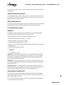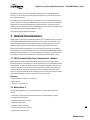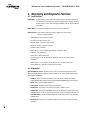
1
TECHNICAL BULLETIN Limitorque MX Actuators Protection, Control and Monitoring Features FCD LMENTB2300-01 – 08/08 Experience In Motion MX Protection, Control and Monitoring Features FCD LMENTB2300-01 – 07/08 Table of Contents Section 1. Standard Control Features 1.1 Basic Specifications 1.2 Local Control 1.3 Remote Control Modes of Operation 1.4 Emergency Shutdown (ESD) 1.5 Remote External Interlocks/Inhibits 1.6 Absolute Position Encoder 2. Protection Features 2.3 Optional Control Features 3. Network Communications 3.1 DDC (Distributed Digital Control) Communication – Modbus™ 3.2 Master Station II 3.3 Foundation Fieldbus Communication 3.4 PROFIBUS DP V1 Communication 3.5 PROFIBUS PA Communication 3.6 Device Type Manager (DTM) for Profibus DP & PA 3.7 DeviceNet 4. Monitoring and Diagnostic Facilities 4.1 Local Facilities 4.2 Diagnostics 4.3 Frequency Domain Analysis 5. Remote Facilities 5.1 Actuator Status Contacts (S1a, S1b, S2a, S2b) 5.2 Monitor Relay (SM) 5.3 Optional Alarm Status Contacts (R1, R2, R3, R4, R5, R6, R7, R8) 5.4 Exact End Position Indication 6. Auxiliary Power Supply 7. Isolated Commons 8. Bluetooth® Wireless Communications and MX Dashboard™ Software 9. Actuator Configuration 9.1 Non-Intrusive Local Configuration 9.2 Default Configuration 10. MX Specifications 11. Wiring Configurations for the MX 11.1 MX Terminal Block 11.2 Wiring Diagram Matrices 12. MX Wiring Diagrams 13. Network Protocol Connections 13.1 Network Wiring – DDC-Modbus 13.2 Network Wiring – Foundation Fieldbus H1 13.3 Network Wiring – Profibus DP and PA 13.4 Network Wiring – DeviceNet 2 Page 5 5 5 6 7 7 7 8 9 11 11 11 12 12 12 13 13 14 14 14 15 18 18 18 19 19 19 19 20 21 21 21 22 25 25 25 29 34 34 36 37 39 MX Protection, Control and Monitoring Features FCD LMENTB2300-01 – 07/08 Figures and Tables Section Figure 1.1 – MX Control Panel Figure 1.2 – Absolute Position Encoder Figure 4.1 – FFT of a sound, efficient worm gear set Figure 4.2 – FFT of an actuator exhibiting a specific component that is out of tolerance due to excessive wear. Figure 4.3 – FDA analysis can be performed at the actuator and is included in its View Diagnostics menus. Figure 4.4 – Normal and Diagnostic Displays Figure 9.1 – Default Configuration Guidelines Figure 9.2 – Configuring the MX Actuator Figure 11.1 – MX terminal block Figure 11.2 – MX wiring diagram matrix Figure 12.1 – Standard Wiring Diagram for MX Actuators Figure 12.2 – Optional Features Wiring Diagrams Figure 12.3 – DDC, Foundation Fieldbus, Profibus DP V1, and Profibus PA, and DeviceNet Network Wiring Diagrams Figure 12.4 – DDC, Foundation Fieldbus and Profibus Optional Features Wiring Diagrams Figure 12.5 – Remote Wiring Connections Figure 13.1 – Typical Modbus Network Wiring Diagrams – Single Loop Figure 13.2 – Typical Foundation Fieldbus System with a DCS Host (Daisy Chain Shown) Table 13.1 – Specifications for the Profibus cable Table 13.2 – Maximum Segment Length Figure 13.3 – Typical Profibus System with a DCS Host (Daisy Chain Shown) Table 13.3 – Belden Cable Specifications Table 13.4 – Total cable length between repeaters or nodes: Page 5 7 15 16 16 17 21 22 25 27 29 30 31 32 33 35 36 37 38 38 39 39 3 flowserve.com MX Protection, Control and Monitoring Features FCD LMENTB2300-01 – 07/08 Introduction This document details the protection, control and monitoring capabilities of the MX range of electronic actuators. The Flowserve Limitorque MX non-intrusive actuator consists of a mechanical gearbox powered by an electric motor. It is controlled by an integral electromechanical starter and state-of-the-art SMT (surface mount technology) controls. Each MX is double-sealed and weatherproof to IP68 (15 m - 96 hours), NEMA 4, 4X, and 6, with hazardous location versions available. Please refer to LMENIM2306 for detailed menu configurations. Standard Application Voltages with +/- 10% Nominal Range Design Voltage Application Voltage 24 VDC* 24-48 VDC* 115 VAC, 60 Hz, 1 ph* 110/115/120 VAC, 60 Hz, 1 ph* 230 VAC, 60 Hz, 1 ph* 230 VAC, 60 Hz, 1 ph* 230 VAC, 50 Hz, 1 ph* 4 230 VAC, 60 Hz, 3 ph 208/220/230/240 VAC, 60 Hz, 3 ph 460 VAC, 60 Hz, 3 ph 380/400/415/440 VAC, 50 Hz, 3 ph 380/440/460/480 VAC, 60 Hz, 3 ph 525 VAC, 50 Hz, 3 ph 525 VAC, 50 Hz 575 VAC, 60 Hz, 3 ph 550/575/600 VAC, 60 Hz, 3 ph Please contact Flowserve Limitorque for other voltage requirements. *Future Implementatioin MX Protection, Control and Monitoring Features FCD LMENTB2300-01 – 07/08 1. Standard Control Features 4 5 1 2 3 1.1 Basic Specifications A matrix of all MX wiring diagrams is shown in Figure 11.2. The standard wiring diagram is shown in Figure 11.1. Optional wiring diagrams are on subsequent pages. The most current wiring diagram is located within the terminal compartment. The following control features are included in the basic specification. For Optional Features, please refer to Section 2.3 Optional Control Features. 1.2 Local Control The Control Panel includes a red Local/Stop/Remote selector switch (padlockable in all three positions; a ¼” (6 mm) hasp is recommended) and a black Open/Close rotary switch (spring-return to center). The Open and Close switches may be configured to allow either push-to-run (inching) control or maintained control. Figure 1.1 – MX Control Panel OTE REM STOP LOC AL OP (YE EN S) ) (NO E OS CL Local Indication The Control Panel includes the following: • 32-character graphical LCD Displays valve position as “PERCENT OPEN” and the current actuator status. • Red/Green LED Indicators – the color assignment for the red and green LEDs is reversible as standard. Red ON = Valve fully open Red “BLINKING” = Valve opening Green “BLINKING” = Valve closing Green ON = Valve fully closed 5 • Yellow LED Yellow ON = Actuator available for remote operation, = Valve stopped in Intermediate position. UNLESS OTHERWISE SPECIFIED: DIMENSIONS ARE IN INCHES TOLERANCES: FRACTIONAL± ANGULAR: MACH± BEND ± TWO PLACE DECIMAL ± NAME DRAWN CHECKED ENG APPR. DATE flowserve.com TITLE: MX Protection, Control and Monitoring Features FCD LMENTB2300-01 – 07/08 Yellow “BLINKING” = Monitor Relay de-energized, actuator not available for remote operation. • Blue LED Bluetooth option enabled and link established 1.3 Remote Control Modes of Operation The actuator may be controlled remotely by two, three or four wires. • Four-Wire Control – Three momentary contacts. Valve can be opened, closed or stopped. • Two-Wire Control – Single open or closed contact. Valve can be opened or closed, but not stopped in mid-travel. • Three-Wire Maintained – Two momentary contacts for self-maintained control. Valve can be opened or closed but not stopped in mid-travel. • Three-Wire Inching – Two “push-to-run” contacts. Valve can be opened, closed and stopped in mid-travel. Refer to Figure 12.5 for remote wiring connections. Remote Control Type The actuator may be placed in digital only, modulation only, network only, or multi-command types. • Digital Only Control Type – Only digital input commands are recognized and acted upon. All other types of remote control commands are ignored. • Modulation Only Control Type – Only Modutronic 4-20 mA (optionally 0-20 mA) commands are recognized and acted upon. All other types of remote control commands are ignored. • Network Only Control Type – Only network (DDC, Fieldbus, Profibus, Device Net) commands are recognized and acted upon. All other types of remote control commands are ignored. • Multi-command Type – All remote control command types are recognized and acted upon, on a “last command in” basis. • MX Multi-control Mode Operation - there are three modes of remote control when remote mode is configured for multi control: digital control, analog control, and network control. Digital and network control operation is based on the last command received. Analog operation is initiated by either toggling user input 2 (configure for CSE input) or breaking & reapplying the analog control. Remote Control Signal Power Power for remote control signals may be derived internally from the actuator or provided externally by the user. Signals can range from 24 to 125 VAC or VDC. External Power Supply An external power supply in the range of 12 to 24 VDC may be provided by the user. Standard Internal Power Supply 6 The standard internal signal supply is 24 VDC. The 24 VDC supply offers a maximum loading of 5 W. The 24 VDC supply, in conjunction with the opto-isolated digital inputs, allows control from remote volt-free contacts over long distances and simplifies the user’s control scheme. An optional 120 VAC, 15 VA internal power supply is available (consult factory). Standard control employs a negative earth. Positive earth (negative switching) is available by wiring to the (+) positive common as shown on the wiring diagrams. MX Protection, Control and Monitoring Features FCD LMENTB2300-01 – 07/08 1.4 Emergency Shutdown (ESD) Up to three independent ESD signals may be applied, prioritized and configured for different actions for the ESD event associated with each. Either of these ESD signals may be applied to the actuator to override any existing command signal and send the valve to its preselected shutdown position, providing the actuator is in Remote mode (default configuration for ESD is “Ignore, take no action”). Any new command signal will be ignored until the ESD signal is removed. During setup, the actuator may be configured to close, open, stop, take no action, or “move to a previously configured position” on receipt of the ESD signal. The ESD action may also be configured to override any inhibit signal, the local selector switch, the local stop switch, an overtorque condition, lost phase, or jammed valve protection. Motor thermal protection may be bypassed for critical ESD applications in non-hazardous or special service locations. Disabling the motor thermostat voids all third-party certifications, including Factory Mutual, CSA, ANZex, and ATEX. 1.5 Remote External Interlocks/Inhibits Three user-defined inputs are provided for the connection of remote contacts that will prevent motorized operation of the actuator. These are effective in both Remote and Local modes and may only be overridden by a maintained ESD signal, if so configured (refer to Figure 12.5 for wiring connections). For ESD connections, the user may select either a single common or isolated commons. 1.6 Absolute Position Encoder An absolute position encoder (patent pending), incorporated into MX actuators, includes 18 phototransistors which are switched on and off by a gear/wheel mechanism. Valve position is sensed by an 18-bit, optical, absolute position encoder with redundant position sensing circuits designed for Built-In Self-Test (BIST). Each of the position sensing circuits is redundant, facilitating BIST. The BIST feature discerns which failures will signal a warning only and require a warning plus safe shutdown of the actuator. Open and closed positions are stored in permanent, nonvolatile memory. The encoder measures valve position at all times, including both motor and handwheel operation, with or without power present, and without the use of a battery. The absolute encoder is capable of resolving ±7° of output shaft position and over 10,000 output drive rotations. This design permits continuous monitoring of valve position during motor and handwheel operation. The encoder is 100% repeatable and requires no backup power source for operation. The output is used to control the open and closed valve position and measure and report valve position, as well as provide local and remote position feedback. The positioning accuracy is better than 99% for valves requiring 50 or more turns. • Maximum actuator turns = 10,000 • Resolution = ± 7 degrees Figure 1.2 – Absolute Position Encoder 18-bit optical, redundant position encoder provides continuous valve position monitoring without battery backup with Built-In Self-Test (BIST) capabilities. 7 flowserve.com MX Protection, Control and Monitoring Features FCD LMENTB2300-01 – 07/08 2. Protection Features LimiGard™ Circuit Protection MX actuators include LimiGard™ (US Patent 5,719,559 dated February 17, 1998) circuit protection. LimiGard™ consists of dedicated circuitry that continually monitors the motor contactor, control relays, internal logic circuits, and external command signals. When the recommended wiring connections are made, it virtually eliminates unexpected erroneous actuation caused by internal electronic failures and erratic external command signals. Additionally, in the event of malfunction, LimiGard™ supervises the actuator response, detects the source of the failure, and signals an alarm. The voltage across the control solid-state output drivers is monitored by LimiGard™. If the voltage level remains valid and no motor movement is sensed or motor contractor feedback is detected, then a motor contactor failure is diagnosed. Motor control solid-state output drivers and series-redundant solid-state output drivers are controlled by signals that must have the proper form to permit turn-on. If either the direction driver or the safety driver is damaged, or if the drive signals do not have the proper form, then the motor contactor will not be able to turn on. Any open circuit, short circuit, or component failure will alter the waveform, disabling the output and setting a monitor relay alarm. This unique protection feature prevents inadvertent, unexpected or dangerous valve movement that could otherwise occur when other circuit components fail. Additionally, LimiGard™ uses dual seriesredundant solid-state drivers for motor contactor control. These consist of an open or close driver and an operation enable driver. Both drivers must be on for the motor to run, but only one needs to be off to stop the valve. The use of two drivers prevents an inability to stop the actuator due to a relay failure. All LimiGard™ alarms are signalled by de-energizing the monitor relay and communicated via the diagnostic screens. Valve operation is inhibited until the failure is corrected; referred to as “Fail No Action.” LimiGard™ requires that external control signals (Open-Stop-Close-ESD-Inhibit) have a minimum pulse width of 250–350 ms to be considered valid. This minimum pulse width ensures that brief, noisy signals will not cause the valve to move. The signal must have a level of 17–22 V to turn on the input, and the input will not turn off until the level drops below 5–10 VDC. This “signal hysteresis” (> 8 VDC) prevents weak and erratic signals from stopping or initiating valve operation. Additionally, LimiGard™ incorporates optical couplers to protect the input circuits from high voltage transients on the remote control signals. The LimiGard™ feature may also be extended to external wiring (customer supplied). One method of securing the external wiring is shown in Figure 12.5. Proper function depends upon setting Remote Input mode to “LimiGard,” which configures redundant inputs for the OPEN, CLOSE, and STOP inputs. Both OPEN or CLOSE signals must be present to allow motor motion, while loss of either STOP signal will stop the actuator and prevent further operation in REMOTE mode. The customer is responsible for external wiring system safety. LimiGard has been enhanced with the addition of the 18-bit encoder with BIST and redundant sensing circuits. Autophase Protection and Correction 8 The phase rotation of the incoming three-phase supply is continuously monitored. In the event that field wiring is reversed, MX controls automatically correct to ensure the valve operates in the commanded direction. In addition, the detector circuit monitors the presence of all three phases. If a phase is lost, valve starting will be prevented and the user alerted via an LCD error message and Monitor Relay Alarm. Jammed Valve Protection If the actuator cannot overcome the required valve starting torque, a jammed valve condition occurs. Jammed valve protection senses the lack of valve movement and initiates a brief reverse/forward MX Protection, Control and Monitoring Features FCD LMENTB2300-01 – 07/08 cycle to free the valve. If this is unsuccessful, further electrical operation is prevented and the monitor relay is signaled. Instantaneous Reversal Protection The control logic incorporates a brief time delay (from 0.5 to 1.0 seconds) between motor reversals. This reduces motor current surges and prolongs the life of the contactor. Note: It is not necessary to switch to STOP before reversing the actuator. Motor Thermal Protection The motor is protected against overheating by a thermistor embedded in the motor windings. Standard thermistor threshold is set for 120˚C (Class B). Options are available for other classifications. 2.3 Optional Control Features Modutronic The Modutronic controller will alter valve position in proportion to an analog command signal. It includes an automatic pulsing mode to reduce overshoot at the set point. The following parameters may be easily set during the configuration of the unit: • Proportional Band range from 0.1% to 100% (15% = default) • Dead Band range from ± 0.1% to 50% (2% = default) • Polarity 20 mA = OPEN (default) or 20 mA = CLOSE • Action on loss of command signal OPEN, CLOSE, STOP (CLOSE = default), or Move-to a previously configured position • Delay after stop 0–60 seconds (0 = default) • Command Signal • 4–20 mA • Input impedance - 150 ohms Repeatability – The Modutronic is repeatable to within ±0.5%. Repeatability is defined as encoder feedback position versus position command. Overall valve and actuator system accuracy depends on many factors, including actuator gearing backlash and valve/actuator coupling tolerance, and therefore cannot be defined by this document. Extrema Mode – If the command signal represents a position of 0–2% OPEN (nominal 4.00–4.32 mA) or 98–100% OPEN (nominal 19.68–20.00 mA), then the MX will move the valve directly to that position, without pulsing. Positioning Frequency – The standard frequency is suitable for a rate of 600 starts/hour for short periods, typical of process start-up. Typical process control of ≤ 100 starts/hour. An optional solidstate motor reverser (SSMR) is available for process rates > 600–1200 starts/hour. Analog Position Transmitter (APT) The APT is an internally powered, non-contacting valve position transmitter. The isolated output signal is proportional to the position of the valve and is available as 4–20 mA and/or 0-20 mA, 0-10 VDC, 2-10 VDC, 0-5 VDC, or 1-5 VDC. 9 The user may select the minimum signal to represent either the fully OPEN or the fully CLOSE position of the valve during the setup procedure. flowserve.com MX Protection, Control and Monitoring Features FCD LMENTB2300-01 – 07/08 • Accuracy = 99% of full scale value (for Drive Sleeve Turns > 50) • Non-Linearity = ± 1% of full scale value • Impedance = 0–600 ohms (4–20 mA signal) • Minimum external load = 1000 ohms (0–10 VDC signal) Analog Torque Transmitter (ATT) The ATT is internally powered and provides an electrically isolated output signal of 4–20 mA and/ or 0-20 mA, 0-10 VDC, 2-10 VDC, 0-5 VDC, or 1-5 VDC, which is proportional to actuator rated output torque. • Accuracy = 99% of full scale value • Non-Linearity = ± 1% of full scale value • Impedance= 0–600 ohms (4–20 mA signal) • Minimum external load = 1000 ohms (0–10 VDC signal) Two-Speed Timer A two-speed pulsing timer can be enabled to extend the operating time in the close and/or the open directions. Pulsing may be applied from 0.5 (if precision is set to xxx.x%) to 99% of full valve travel or to a small portion. The ON pulsing cycle is configurable from 0.5 to 20 seconds in 0.5 second increments, and the OFF pulsing cycle is configurable from 1.0 to 200 seconds in 1 second increments. The two-speed timer is especially effective where concerns of hydraulic shock exist. Control Station (CSE) The CSE is a separate control station designed for the operation of inaccessible actuators. It is available with LEDs, Remote/Local and Open/Close selector switches. The CSE may be powered by the actuator internal supply, provided wire resistance and other external loads do not limit the available signal power presented to the MX. Isolation and Load Break Switches Isolation and Load Break Switches can be supplied for the incoming three-phase supply to the actuator. These may be coupled directly to the actuator for weatherproof (WP) applications only or supplied separately for mounting by user. The enclosure is suitable for weatherproof or temporary submersion service. An explosion-proof (XP) isolation switch is also available for user mounting. It is suitable for mounting with all MX actuators. Please contact factory for availability. Lost Power Buffer – MX Quik™ After the actuator has been powered by line power for one hour, it can automatically withstand most power outages while maintaining the correct state of the S or R status contacts, even if the user repositions the actuator manually with the handwheel. To maximize its self-power time while the line power is lost, the actuator places itself in its lowest possible power usage mode. The LCD will darken (sleep mode) until it is needed to be viewed. The LCD can be activated by moving the black knob to OPEN (YES) or by moving the actuator with the handwheel. After the programmable period of inactivity, the LCD returns to sleep mode. The use of batteries to perform this function is not required. 10 Custom Software – Momentary Contact ESD and Partial Stroke ESD An optional, custom software has been developed which, when combined with the unique safety features of the MX actuator, permits a unique scope of performance for Partial stroke and Emergency Shutdown installations. MX Protection, Control and Monitoring Features FCD LMENTB2300-01 – 07/08 When enabled, a User may set up the partial stroke and ESD signals as redundant digital inputs for safety. There are two signal inputs for either selection, and both must be in the active state in order for the specific function to occur. If the partial stroke enable inputs are not active, in a fault state, or are released by the control logic and a signal is detected on the momentary ESD/PSESD input, then the actuator will perform the configured ESD operation. The momentary ESD/PSESD input will be ignored if there is a signal present for less than 100 msec, and is guaranteed to latch in the ESD/PSESD if the signal is present for greater than 800 msec. ESD is active until the control logic ESD Release is given. Please contact factory for application and purchase. 3. Network Communications The MX provides a comprehensive network option portfolio to the user. Network solutions are improved with the addition of DeviceNet to complement Modbus, Foundation Fieldbus H1, Profibus DP_V1 and Profibus PA. MX provides the user with predictable, reliable, and safe operation for years to come, in applications which are subject to the most rigorous requirements and environmental extremes. With each of the provided network protocols a user may configure the unit to move to a predefined fail-safe position on loss of communication. Action on loss of command signal OPEN, CLOSE, STOP, or MOVE-TO preconfigured position. The user may also configure the length of time communication must be lost before the unit indicates communication loss and performs the communication loss action. 3.1 DDC (Distributed Digital Control) Communication – Modbus™ DDC is Flowserve Limitorque’s digital communication control system that provides the ability to control and monitor up to 250 actuators over a single twisted-pair cable. The communication network employs Modbus™ protocol on an RS-485 network and is redundant. Redundancy assures that any single break or short in the communication cable will not disable any actuators. Each actuator has included an addressable field unit that communicates over the twisted pair network and executes open, close, stop, ESD, and GO TO position commands. The field unit also communicates all actuator status and alarm diagnostic messages over the same communication network. DDC Network • Single-ended loop (as standard – See Figure 13.1) • Modbus protocol • High speed – up to 38.4K baud 3.2 Master Station II MX units equipped with DDC can be controlled via Flowserve Limitorque’s Master Station II. It includes: • Host interface – RS-232 or RS-485 with TCP-IP (Ethernet) as standard (Modbus™ protocol) • LED indicator for network status • Configurable polling sequence priority • Configurable bitmap to host • Redundant RS-485 network ports 11 • High-level surge protection on network • Logging port for maintenance PC flowserve.com MX Protection, Control and Monitoring Features FCD LMENTB2300-01 – 07/08 3.3 Foundation Fieldbus Communication MX can be fitted with Foundation Fieldbus protocol that complies with the IEC 61158-2 Fieldbus H1 standard. The field unit device is able to support several topologies, such as, point-to-point, bus with spurs, daisy chain, tree, or a combination of these. The FF device has network features that include: • Link Active Scheduler that controls the system • High-speed communications up to 31.25 kbits/sec • Publisher - subscriber communication • One analog input block, one analog output block, two discrete output function blocks, Transducer block, Resource block, and four discrete input function blocks • PID (proportional integral derivative) loop control (future) • Device descriptions • Configurable by user Link Active Scheduler communication: Fieldbus segments have one active Link Active Scheduler (LAS) at a given time, which is the bus arbiter, and does the following: • Recognizes and adds new devices to the link • Removes non-responsive devices from the link • Schedules control activity in, and communication activity between, devices • Regularly polls devices for process data • Distributes a priority-driven token to devices for unscheduled transmissions 3.4 PROFIBUS DP V1 Communication MX can be fitted with Profibus DP_V1 protocol field units that comply with EN50170 Fieldbus Standard for RS-485 communications. The device supports several topologies, such as, pointto-point, bus with spurs, daisy chain, tree, or a combination of these. The PB device has network features that include: • High-speed communications up to 1.5 m/bits/s • Master-to-slave communication • Slave redundancy (optional) • One analog input block, one analog output block, two discrete output function blocks, Transducer block, Physical block, and four discrete input function blocks • Device descriptions configurable by user High-Speed Data Exchange – Startup Sequence • Power ON / Reset – Power On / Reset of master or slave • Parameterization – download of parameters into field device (selected during configuration by the user) • I/O Configuration – download of I/O configuration into the field device (selected during configuration by the user) • Data Exchange – cyclic data exchange (I/O Data) and field device reports diagnostics 12 3.5 PROFIBUS PA Communication A Profibus PA protocol is available and complies with EN50170 Fieldbus Standard and Fieldbus physical layer per IEC 61158-2 for communications. The device supports several topologies, such MX Protection, Control and Monitoring Features FCD LMENTB2300-01 – 07/08 as point-to-point, bus with spurs, daisy chain, tree, or a combination of these. The PB device has network features that include: • High-speed communications up to 31.25 kbits/s with Manchester coding • Master-to-slave communication • Bus powered for 9-32 VDC and 15 mA per actuator • Stand-by communication channel • One analog in and one analog out, four digital input and up to eight digital output function blocks • Device descriptions configurable by user 3.6 Device Type Manager (DTM) for Profibus DP & PA A software component which can be downloaded from www.limitorque.com and integrated into Field Device Tool (FDT) frames for: • offline/online parameterization • configuration • status updates • diagnostic retrieval 3.7 DeviceNet DeviceNet complies with CAN based protocol and provides the following features: • DeviceNet Group 2 Server implementation. • Bus Powered Network Interface allows power alarm information to be communicated when actuator loses main power. The actuator does NOT drop off the network when 3-phase power is lost. • Standard Polled I/O Connection • Standard Bit Strobed I/O Connection • Standard Change of State / Cyclic I/O Connection • Standard explicit connections defined as: • Various Assembly Objects and sizes that allow the network user to determine how much data to transfer to accommodate network installation data throughput requirements. • Automatic BAUD rate detection. • Node Address configurable via local setup menu, or via the remote network user. • Broadcast or group network originated ESD support. The following commands and information may be transmitted over the DeviceNet network: • “OPEN,” “STOP,” and “CLOSE” commands • “ESD” and “MOVE–TO” position commands • Actuator status and alarm messages • Six digital inputs and one analog input and output for user • A surge-protected and isolated communication channels 13 • MX control panel configuration • Torque output (for reference only) and position feedback • Four digital outputs (standard) with four additional digital outputs (optional) Please see Section 13 for network connection topologies and cabling recommendations. flowserve.com MX Protection, Control and Monitoring Features FCD LMENTB2300-01 – 07/08 4. Monitoring and Diagnostic Facilities 4.1 Local Facilities LCD Displays – The LCD displays an array of data concerning the status of actuator components in clear, graphical or textual language. The MX is available with ten languages: English, Spanish, German, French, Italian, Portuguese, Mandarin, Russian, Bahasa Indonesia and Katakana. Normal Display – The normal display illustrates current valve position and status. Alarm Functions – A larm functions (active alarms will be toggled every four seconds) that may be displayed include: • Valve Jammed - Valve cannot start moving • Lost Phase - One of three phases lost • Motor Overtemp - Thermistor range exceeded • Overtorque - Torque exceeded in mid-travel • Hardware Failure - Indication • DDC, Profibus, Foundation Fieldbus, DeviceNet off - Enabled, but “OFF” • ESD Active - ESD signal active • Inhibit Active - Inhibit signal present • No analog signal - 4–20 mA signal absent (Modutronic enabled, red selector switch in “REMOTE”) • DDC, Profibus, Foundation Fieldbus, DeviceNet comm loss - Enabled, signal absent • Analog Output Loss - Enabled, but output current loop open 4.2 Diagnostics Standard Diagnostic Screens – Diagnostic screens may be accessed quickly through the Setup dialogue or the MX Dashboard Software solutions package. These screens provide detailed data of actuator status. Included are: • Hardware – status of electronic components such as thermistor, encoder, power board, DDC/FF/PB/DeviceNet network board, analog board, DIGIN and ANIN (digital in and analog in) • Motor – Phase rotation, winding temperature • Power Supply – Maximum and minimum voltage, frequency • Identification – Tag number, serial number, order number, software revision • Torque Profile – Record of the REFERENCE and the LAST reading of the breakout, peak running and ending torques, in both the open and close directions. Torque is displayed for reference only. • View DNET Status – Checks for Standby, Recoverable Fault, Nonrecoverable Fault, and View Network Status • Operation Log – Actuator turns, contactor operations, motor run-time, stroke time, manual operations 14 MX Protection, Control and Monitoring Features FCD LMENTB2300-01 – 07/08 • View Control Compartment Temperature (View Power Supply Menus) • View FDA (Frequency Domain Analysis) 4.3 Frequency Domain Analysis (patent pending) The Frequency Domain Analysis (FDA) methodology for the MX is based upon capturing torque, position, or speed values at regular time intervals while the actuator is motoring, and then calculating the resulting data set with a Fast Fourier Transform (FFT). This converts the actuator’s torque, position, or speed signature from the time to the frequency domain. The resulting information is very useful for pinpointing any components in the mechanical drive train that have failed or are about to fail. For example, if some part of the mechanical system has been fabricated with a physical defect, has been exposed to severe operational levels, or is nearing the end of its normal life, the FDA will be able to detect and report a frequency variation in a chart or plot that can be correlated to the damaged part when compared to the baseline. MX FDA is established during the End of Line test analysis of the actuator after assembly and prior to shipping. This is “FDA Baseline” and is unique for each MX that ships to a customer. Once the MX has been assembled to a valve, the OEM or end user can record “FDA #2”, the signature for that unique MX and valve combination. Both of these traces are stored in non-volatile memory, which protects the data from spurious events. Each time the MX and valve combination is cycled in the field, FDA #3 is recorded. This data is refreshed with each cycle, ensuring that the very latest FDA is retained for analysis. Only the Flowserve Limitorque MX has the FDA feature in its View Diagnostics menus. FDA can also be downloaded to the Dashboard software tool for viewing and analysis. Figure 4.1 – FFT of a sound, efficient worm gear set 100% 90% 80% Magnitude (Normalized) 70% 60% 50% 40% 30% 20% 10% 0% 0 1000 2000 3000 4000 5000 6000 7000 8000 9000 10000 RPM 15 flowserve.com MX Protection, Control and Monitoring Features FCD LMENTB2300-01 – 07/08 Figure 4.2 – FFT of an actuator exhibiting a specific component that is out of tolerance due to excessive wear. 100% 90% 80% Magnitude (Normalized) 70% FFT indications of worn or out-of-tolerance components. When compared with the baseline (Figure 4.1), each peak can be associated with a particular suspect part, e.g. worm, encoder, motor, etc. 60% 50% 40% 30% 20% 10% 0% 0 1000 2000 3000 4000 5000 6000 7000 8000 9000 10000 RPM Figure 4.3 – FDA analysis can be performed at the actuator and is included in its View Diagnostics menus. 16 MX Protection, Control and Monitoring Features FCD LMENTB2300-01 – 07/08 Figure 4.4 – Normal and Diagnostic Displays Normal Display – STATUS OK confirms that the actuator is suitable for remote operation. Normal Display/Alarm Condition – If the actuator is not suitable for remote operation, the appropriate alarm will be shown. Diagnostic Display informs user of failed hardware. Typical Display 17 flowserve.com MX Protection, Control and Monitoring Features FCD LMENTB2300-01 – 07/08 5. Remote Facilities 5.1 Actuator Status Contacts (S1a, S1b, S2a, S2b) Four latched contacts provide remote feedback of actuator status. Two (S1a, S2a) contacts may be individually configured for normally open, normally closed, or blinker (continuous opening and closing of the valve) operation and provide feedback of one of the functions listed below. Two other relays are complementary. • Closed • Motor overtemp • Closing • Overtorque • Mid-travel • Open torque switch • Opening • Close torque switch • Open • ESD signal • Stopped • Open inhibit • Valve moving • Close inhibit • Local selected • Lost phase • Local STOP/OFF • No analog signal • Manual operation • Hardware failure • Valve jammed • Network controlled • Remote selected • CSE controlled Default settings are: • S1a – Normally closed contact at valve fully CLOSE • S1b – Normally closed contact at valve fully OPEN • S2a – Normally open contact at valve fully CLOSE • S2b – Normally open contact at valve fully OPEN The standard contacts are rated for 2.0 A at 30 VDC and 0.5 A at 125 VAC. 5.2 Monitor Relay (SM) The monitor relay provides immediate indication of problems that prevent remote valve operation. It has a normally open contact and a normally closed contact (1 x SPDT contact) and is energized when the three-phase supply is present and the actuator is in a normal/healthy state. The relay will de-energize if any of the following events occur: • Loss of one or more phases of the three-phase power supply • Loss of internal control supply • Jammed valve detected • Motor overtemp is active (unless thermostat is configured to OFF) • Selector switch is in “Local” mode • Selector switch is in “Stop” position 18 MX Protection, Control and Monitoring Features FCD LMENTB2300-01 – 07/08 During configuration, the following parameters may be added to the monitor relay function: • Overtorque • Inhibit signal active • ESD signal active (The user can enable or disable “local” mode and “stop” position. Default is enabled.) The monitor relay resets when the faulty state is rectified. The standard contacts are rated for 2.0 A at 30 VDC and 0.5 A at 125 VAC. An optional monitor relay (RM) is available with contacts rated for 5.0 A at 250 VAC, 30 VDC. The monitor relay can be disabled if the user chooses. 5.3 Optional Alarm Status Contacts (R1, R2, R3, R4, R5, R6, R7, R8) As an option, up to eight additional latched status contacts may be included. These may be configured in an identical manner to the S contacts. Default configuration is: • R1 – Normally closed contact at valve fully CLOSE • R2 – Normally closed contact at valve fully OPEN • R3 – Normally open contact at valve fully CLOSE • R4 – Normally open contact at valve fully OPEN • R5 – Closed contact when motor over temperature • R6 – Closed contact when remote selected • R7 – Closed contact when overtorque • R8 – Normally open contact when analog I/P (input) lost The contacts are rated 5.0 A at 250 VAC, 30 VDC. 5.4 Exact End Position Indication On torque-seated valves, the end-of-travel indication switch trips when the required torque is achieved at the end of travel—not at the calibrated position limit. This ensures that remote, selflatched signals will not be disconnected prematurely, and that the valve will be tightly seated. 6. Auxiliary Power Supply - Uninterruptible Power Supply (UPS) Connection If the main three-phase power supply is not available during the configuration of the actuator, an optional module contains provisions for connecting a 24 VDC, 1 A power source to the auxiliary input terminals shown in the wiring diagram on the following pages. Power supply will draw up to 0.5 A. 7. Isolated Commons The MX is provided with isolated commons for control functions. Please refer to wiring diagram on page 29 for locations. 19 flowserve.com MX Protection, Control and Monitoring Features FCD LMENTB2300-01 – 07/08 8. Bluetooth® Wireless Communications and MX Dashboard™ Software A Bluetooth option is available that permits a user to download or upload configuration routines via a standard low power wireless communication path to an actuator. The MX actuator can communicate via Bluetooth with a Bluetooth-equipped PC, PDA, or cell phone compatible with the Microsoft Windows® Mobile platform and the MX Dashboard actuator diagnostics GUI (Graphical User Interface) software. The Bluetooth option contains a FHSS (Frequency Hopping Spread Spectrum), which enables a reliable communication link, even in a “noisy” environment. The Bluetooth option also contains 128-bit data encryption to protect the privacy of the link. Bluetooth communication is accessible up to 10 meters from the actuator in all directions and the ability to enable the Bluetooth communication link is password protected. A visible blue LED in the controls LCD window signifies that an active Bluetooth link to the actuator is established. The Dashboard actuator software program permits a user to easily access the diagnostics capability of the MX actuator using a Bluetooth-equipped PC or PDA with the Windows Mobile 5 (or greater) platform. Dashboard is driven by GUI and parallels the menu selections of the MX. It can be used to change or view configurations up to 10 meters from the actuator when a Bluetooth link is established. A secure Bluetooth link must be established before configurations can be altered, ensuring security and safety. Once the link is established, Dashboard can be used to change or view the default configuration in either active on-line mode or background mode. On-line mode permits a user to make unit configuration changes in real time by simply answering “Yes” or “No” to the menu prompts. Exiting the program saves the changes to the MX. These changes can be subsequently downloaded into a Bluetooth-equipped PC or PDA and uploaded to other MX actuators that require identical configurations, speeding setup of the remaining actuators. When background mode is used, a unit configuration can be programmed, saved to a PC or PDA, and uploaded into an MX once the Bluetooth link is established. This feature enables the user to assign a unique configuration for any number of actuators in a non-volatile environment, save it to the computer device, and schedule the upload to the actuators when planned maintenance is performed. Diagnostics can also be downloaded from the actuator into a PC or PDA via Dashboard and saved for further evaluation. Dashboard can be used to analyze this data or e-mail it to Flowserve Limitorque for evaluation. When the MX software is revised, Dashboard can be used to implement newly released software and upload it to the MX. These features are available up to 10 meters from the MX actuator equipped with the Bluetooth option. Dashboard can also be used with the IrDA port supplied with each MX unit. It also requires a link to be established, but the effective communication distance is typically less than one meter to avoid cross-communication with neighboring devices. Please refer to LMENIM2338 for the MX Dashboard Installation, Operation, and Maintenance Manual (IOM). 20 MX Protection, Control and Monitoring Features FCD LMENTB2300-01 – 07/08 9. Actuator Configuration 9.1 Non-Intrusive Local Configuration MX actuators may be configured without removing any covers, or using special tools. Configuration is accomplished through the use of the LCD, Dashboard and the local control switches mounted on the Control Panel. Settings that can be initiated or changed include: • Limit switch trip positions • Torque output levels • Direction of rotation • Action on ESD • External inhibits • Remote control operating mode • Motor thermostat action • Stop valve on torque or position • All optional features (Modutronic, DDC, FF H1, PB-DPV1, PB-PA, DeviceNet, Timers, APT, etc.) 9.2 Default Configuration Unless otherwise specified, MX actuators will be shipped with the following configuration, which becomes effective after limits are set: • Open stop by limit • Close stop by limit • Maintained local controls • Clockwise to close • ESD is “off” and set to “IGNORE.” • Inhibits enabled, turned “OFF” • Remote control – three-wire maintained and Multi-mode • Password – 100 • Modutronic Option (if installed) Figure 9.1 – Default Configuration Guidelines Modutronic Option Proportional band – 15% Deadband – 2% Polarity – 20 mA = Open Action on loss of signal = Close FF Option, DeviceNet and PB Option Analog scale = 0-100 Proportional band – 15% Deadband – 2% Modbus RTU protocol 9600 baud Analog scale = 0-100 Proportional band – 15% Deadband – 2% Offset – 0 mA 21 flowserve.com MX Protection, Control and Monitoring Features FCD LMENTB2300-01 – 07/08 Figure 9.2 – Configuring the MX Actuator 1 Place selector switch in “STOP.” The LCD display will read “% OPEN” and “STATUS OK.” Operate the selector switch to the (YES) (NO) (YES) positions. The message “SETUP?” will be displayed for 10 seconds. Answer “YES” to enter setup routine. 2 All parameters may be configured by answering “YES”/ “NO” questions. For example, entering a “NO” response to the displayed screen will change the displayed torque value. Select “YES” when the desired value is displayed. Configuration screens are displayed in English. Languages such as Spanish, French, German, Italian, Portuguese, Mandarin, Russian, Bahasa Indonesia, and Katakana are also available and can be configured via the actuator control panel. A three-digit numeric password is included as part of the initial setup procedure to prevent unauthorized changing of the configured parameters. If the password is entered incorrectly, settings may be viewed, but not changed. The default value for the password is 100. 10. MX Specifications The MX is the most rigorously tested non-intrusive actuator in the industry and complies with all pertinent global requirements. Please contact the factory should your requirements exceed the listed parameters. Global certifications Standard Non-hazardous certifications - The normal operating temperature range for weatherproof applications is from -30°C to +70°C (-22°F to +158°F). Options are available to -60°C (-76°F). • FM – NEMA 3, 4, 4X and 6. • CSA – Type 3, 4, and 6. • IEC – IP 68 to 15 m for 96 hours. • Submersion – NEMA 6 (6 ft–30 min), IEC529, IP68 (15 m–96 h), Limitorque specification (20 ft–24 h) 22 • Saliferous (Salt) spray – 1500-hour test per ASTM B117-1985. Standard Explosionproof certifications - The normal operating temperature range for explosionproof applications is from -30°C to +65°C (-22°F to +149°F). Options are available to -50°C (-57°F) for FM and CSA. MX Protection, Control and Monitoring Features FCD LMENTB2300-01 – 07/08 • FM – Class 1, Division 1, Group B, C, and D. Class II/III, Division 1, Group E, F, and G – T4 • CSA – Class 1, Division 1, Group C and D. Class II/III, Division 1, Group E, F, and G – T4 • ATEX – EEx d IIB T4 ATEX II 2 G, CENELEC Norm EN50014 and EN50018 • EEx d IIC T4 ATEX II 2 G, CENELEC Norm EN50014 and EN50018 • EEx de IIB T4 ATEX II 2 G, Increased Safety, CENELEC Norm EN50014, EN50018, EN50019 • EEx de IIC T4 ATEX II 2 G, Increased Safety, CENELEC Norm EN50014, EN50018, EN50019 • ANZex – Ex d IIB T4 & Ex de IIB T4 and Ex d IIC T4 & Ex de IIC T4 Wiring • All internal wiring is flame resistant, rated -40°C to 105°C (-40°F to 221°F), and is UL listed. Valve interface • Mounting base conforms to MSS SP-102 or ISO 5210 as required. Steel torque bushings (type B) and bronze thrust nuts (type A) are removable for machining. Design life & endurance • Design Life - One million drive sleeve turns is considered typical life expectancy under normal operating conditions in approved ambient working environments. • Endurance – 50 million collective drive sleeve turns of endurance testing were performed on the MX for proof of design. • AWWA C540-02 – “Standard For Power Actuating Devices For Valves and Sluice Gates” – 5,000 cycles with confirmation of specified torque and position repeatability. Diagnostic features Diagnostic facilities are displayed on the LCD by accessing the diagnostic menu or the MX Dashboard™. It includes: motor data (voltage, current, phase rotation, and temperature), hardware status, and identification (tag, serial order, and software revision), torque profile (comparison of last torque to baseline), and operations log (total turns, contactor operations, valve stroke time, and handwheel operations). Diagnostics also includes a restricted Frequency Domain Analysis (FDA) feature. The FDA methodology captures torque, position or speed values at regular time intervals while the actuator is motoring, and calculates the resulting data set with a Fast Fourier Transform (FFT). The resulting information can be used to isolate any components in the mechanical drive train that may exhibit excessive wear or may effect normal actuator operation. FDA and resultant fault indications can be displayed via the graphical LCD. The actuator also contains the ability for diagnostics information to be downloaded to a PC or PDA via both IRDA and optional Bluetooth ports utilizing MX Dashboard. Factory test Factory testing verifies rated output torque, output speed, motor performance, handwheel operation, local control, control power supply, control features, and baseline FDA. A report confirming successful completion of testing is included within the actuator. Conduit entries 23 Three threaded conduit entries are provided tapped: 1 x 1½" and 2 x 11/4" NPT. The actuator is available with 1 x M40 and 2 x M25 metric to BS3643, and PG adapters are available upon request. flowserve.com MX Protection, Control and Monitoring Features FCD LMENTB2300-01 – 07/08 European Directives All MX actuator designs have been tested to comply with pertinent EU Directives and shipped with the Declaration of Conformity listed in the Regulatory Section of LMENIM2306 and LMENIM2314. The actuator is also tagged with the CE mark to demonstrate compatibility with the following European Directives: Directives 98/38/EC- Machinery, 89/336/EC- EMC – Electromagnetic Compatibility, 73/23/EC & 93/68/ EC – Low Voltage, and 2003/10/EC Airborne Noise. Directives 89/336/EC- Machinery and 73/23/EC & 93/68/EC – LVD; EN 60204 EMC • Vibration and seismic capability in accordance with MILSTD-167, IEEE-344-1975, and IEC682-6. Vibration consists of 5-200-5 Hz sweeps at 0.75 g acceleration in three axes and 2-35 Hz at 1.0 g acceleration in three axes. Seismic is 5.0 g acceleration from 3.5-35 Hz in three axes. • Drop test – ASTM D3332-88, method A as guideline only. • Temperature extremes with humidity – Confirm function of motor, controls, and output torque at -30°C (-22°F) for 72 hours continuous, 70°C (158°F) dry heat for 16 hours continuous and 70°C (158°F) damp heat for 72 hours continuous. The MX has also been subjected to arctic extremes down to -60°C (76°F) and maximum temperatures to 40°C (+104°F). The maximum temperature is limited by the lubrication viscosity. • Di-electric – Motor per NEMA MG1-12.02 and .03 with leakage of less than 10 mA. Control terminals per IEC-1131-2 and CSA C22.2 with check against physical breakdown. Directives 98/37/EC- EMC & 73/23/EC & 93/68/EC – LVD; EN 50081-1 & 2 • Applicable Emissions Standards; EN 50011:1998 • Radiated emissions; EN 55011:1998 & FCC Part 15, subpart J • Conducted emissions; EN 55011:1998 & FCC Part 15, subpart J • Applicable Immunity Standards; IEC EN 61000-6-1:2001 • ESD; IEC 61000-4-1:1995 • Radiated RF Immunity; IEC 61000-4-3:1995 • Fast Transients and Bursts; IEC 61000-4-4:1995 • Voltage Surges; IEC 61000-4-5:1995 • Conducted RF Immunity; IEC 61000-4-6:1996 • Magnetic Field Immunity; IEC 61000-4-8:1993 • Voltage Dips and Interrupts; IEC 61000-4-11:1994 Directive 2003/10/EC Airborne Noise to EN 60204-1 • Airborne sound – 74 dB (at 200 RPM) per grade A noise requirement of MIL-STD-740 and ANSI/ISA-S82.01-1994 (Harmonized std. to IEC 1010-1). 24 MX Protection, Control and Monitoring Features FCD LMENTB2300-01 – 07/08 11. Wiring Configurations for the MX Figure – 11.1 MX terminal block NETWORK GROUNDING LUGS GROUNDING LUG 11.1 MX Terminal Block The standard terminal block for the MX now has 54 points and can sustain all of the options for the MX. Grounding (earth) lugs are provided for both power leads and network control. It is recommended that the machined areas adjacent to the terminal block be used to properly ground any network applications. 11.2 Wiring Diagram Matrices The MX now features a number of flexible options that permit a user to customize the electronic actuator for very specific field applications. The wiring diagram matrix is configured using letters that correspond to options supplied with the ordered actuator. The code is assembled (e.g., MXOXX) where: • MX = family of actuators • OX = relay configuration • X = control configurations 25 flowserve.com MX Protection, Control and Monitoring Features FCD LMENTB2300-01 – 07/08 The relay options can be ordered for a new actuator or added to an existing MX and are listed as follows: • OS = Standard S relays (4 total, 2 configurable, 2 complementary) and (1) Monitor, rated for 2 A/30VDC, 0.5 A/125 VAC • OA = Digital output R option (4), including Monitor, rated for 5 A/30 VDC, 250 VAC • OB = Standard S relays (2), including Monitor, rated for 2 A/30 VDC, 0.5 A/125 VAC and Digital output R option (4), rated for 5 A/30 VDC, 250 VAC • OC = Digital output R2 option (8), including Monitor, rated for 5 A/30 VDC, 250 VAC A standard, no option MX code would be: MXOS. In addition, the following options can be ordered for a new actuator or added to an existing MX: • M = Modulating • I = Analog output (I/O), configurable as APT or ATT • D = DDC Modbus network control • F = FOUNDATION Fieldbus H1 • PV = Profibus DP_V1, RS-485 • PA = Profibus PA • N = DeviceNet • Z = SSMR (Solid State Motor Reverser) • E = Negative switching/positive earth These other options can be supplied with the relay option boards; e.g. OA can be added to the I/O analog output option. When ordered as such, a wiring diagram code can be supplied as “MXOAI.” An MX supplied with an OB, Profibus DP_V1 network board, and SSMR can be ordered as “MXOBPVZ.” The MX wiring diagram matrix is shown on the following page. Please contact Flowserve Limitorque if the option you require is not listed. 26 MX Protection, Control and Monitoring Features FCD LMENTB2300-01 – 07/08 Figure 11.2 – MX wiring diagram matrix Standard-S R S&R 2R APT/ATT Modulating DDC FF PB_DPV1 PB_PA D’Net SSMR* Code OS OA OB OC I M D F PV PA N Z MX+ Wiring Diagram 18-499- OS**** OA OB OC OSI OAI OBI OCI OSM OAM OBM OCM OSMI OAMI OBMI OCMI OSZ OAZ OBZ OCZ OSIZ OAIZ OBIZ OCIZ OSMZ OAMZ OBMZ OCMZ OSMIZ OAMIZ OBMIZ OSD OAD OBD OCD OSDI OADI OBDI OCDI OSDZ OADZ OBDZ OSDZI OSF OAF OBF OCF OSFI OAFI OBFI 0101-3 0112-3 0113-3 0114-3 0115-3 0107-3 0116-3 0117-3 0105-3 0118-3 0119-3 0120-3 0121-3 0108-3 0122-3 0123-3 0124-3 0125-3 0126-3 0127-3 0128-3 0129-3 0130-3 0131-3 0132-3 0133-3 0134-3 0135-3 0136-3 0137-3 0138-3 0139-3 0140-3 0141-3 0142-3 0143-3 0144-3 0145-3 0146-3 0147-3 0148-3 0149-3 0150-3 0111-3 0151-3 0152-3 0153-3 0153-3 0155-3 0156-3 x x x x x x x x x x x x x x x x x x x x x x x x x x x x x x x x x x x x x x x x x x x x x x x x x x x x x x x x x x x x x x x x x x x x x x x x x x x x x x x x x x x x x x x x x x x x x x x x x x x x x x x x x x x x x x x x x x x x x x x x x x x x x 27 MX Protection, Control and Monitoring Features FCD LMENTB2300-01 – 07/08 Standard-S R S&R 2R APT/ATT Modulating DDC FF PB_DPV1 PB_PA D’Net SSMR* Code OS OA OB OC I M D F PV PA N Z MX+ Wiring Diagram 18-499- x x OCFI OSFZ OAFZ OBFZ OSPV OCFZ OSFZI OAPV OBPV OCPV OSPVI OAPVI OBPVI OCPVI OSPVZ OSPVZI OAPVZ OBPVZ OSPA OAPA OBPA OCPA OSPAI OAPAI OBPAI OCPAI OSPAZ OAPAZ OSPAZI OSN OAN OBN OCN OSNI OANI OBNI OCNI OSDZ OADZ OBDZ OSDZI 0157-3 0110-3 0158-3 0159-3 0109-3 0201-3 0197-3 0160-3 0161-3 0162-3 0163-3 0164-3 0165-3 0166-3 0167-3 0169-3 0168-3 0198-3 0170-3 0171-3 0172-3 0173-3 0174-3 0175-3 0176-3 0177-3 0178-3 0179-3 0180-3 0181-3 0106-3 0182-3 0183-3 0184-3 0102-3 0185-3 0186-3 0187-3 0188-3 0200-3 0189-3 x x x x x x x x x x x x x x x x x x x x x x x x x x x x x x x x x x x x x x x x x x x x x x x x x x x x x x x x x x x x x x x x x x x x x x x x x x x *The addition of the SSMR permits only three option boards Note: Positive earth (negative switching) available for all options – consult wiring diagram or factory 28 x x x x x x x x x x x x x x x x x x x x x x x x x MX Protection, Control and Monitoring Features FCD LMENTB2300-01 – 07/08 12. MX Wiring Diagrams Transformer Tapping Options Figure 12.1 – Standard Wiring Diagram for MX Actuators TYPE Circuit shown with valve in fully closed position and power off 3 PHASE SUPPLY 1 GROUP 1 CLOSE 27 STOP 26 OPEN 25 GROUP 2 SEE TABLE 1 INPUT 1 212 V 220 V 380 V 505 V 525 V 200 V 208 V 392 V 400 V, 415 V 220 V 220 V 450 V 440 V, 460 V, 480 V 2 TYPE 3 530 V 550 V 572 V 575 V, 600 V GROUP 3 DIG COM #2A CONTROL SUPPLY INPUT 0 DIG COM #3-Ve DIG COM #3A BACK-UP 24 VDC UPS POWER MAY BE CONNECTED TO TERMINAL'S 6 AND 7. MAXIMUM CURRENT DRAW IS 1 AMP. THIS POWERS ALL CONTROLS FOR LOCAL INDICATION AND CONFIGURATION., INCLUDING ANALOG OUT AND NETWORK COMMUNICATION. REVERSING CONTACTOR WILL NOT BE POWERED. 35 AUXILIARY INPUT SEE NOTE 2 &10 (OPTIONAL) 34 SEE NOTE 5 CUSTOMER MUST SUPPLY EXTERNAL FUSE AS REQUIRED 30 110 VAC 24 22 24 VDC +Ve 0 VDC 3. MAXIMUM EXTERNAL LOAD TERMINALS 21 AND 22 (24 VDC) - 5 W MAX. EXT. LOAD TERMINALS 23 AND 24 (OPT. 110 VAC) - 20 W MAX EXT. LOAD, 15 VA 32 33 23 24 VDC +Ve BY LOCAL ELECTRICAL CODES. 31 0 VAC 21 6 7 STATUS FEEDBACK OUTPUT SWITCHES SEE NOTES 6,7,8 & 9 DEFAULT SETTING 44 S1a 600 VAC, 1 A, 200 kA Int RATING, FAST ACTING 10.3 x 38.1 mm TUBE. FS3 (SECONDARY) - 0.1 A, 250 V, TIME DELAY, 5 x 20 mm, GLASS TUBE 29 DIG COM #2-Ve 0 VDC LIMIGARD TYPE 2. AUXILIARY INPUT (OPTIONAL W/ BACKUP POWER BOARD) 28 INPUT 2 SEE TABLE 1 APPL. VOLTAGES 226 V, 260 V, 240 V 366 V FSI (PRIMARY) FS2 FS3 TAPS 226 V 115 V, 120 V FS2 (PRIMARY) DIG COM #1-Ve (OPTIONAL) APPL. VOLTAGES 1. FUSES REMOTE INPUTS SEE NOTE 4 L3 FS1 TAPS PE L1 REVERSING CONTACTOR APPL. VOLTAGES 110 V 115 V NOTES: (SEE INSTALLATION & OPERATION MANUAL FOR DETAILS – LMENIM2306) L2 MOTOR TAPS 106 V 4. REMOTE INPUTS } OPT. SIGNAL THRESHOLD - MINIMUM "ON" 19.2 VAC/VDC MAXIMUM "OFF" 5.0 VAC/VDC MAX LOAD - 10 mA / 110 VAC 2 mA / 24 VDC REQUIRED CONTROL SIGNAL DURATION = 350 ms MIN. INPUTS 0,1,2 ARE FIELD CONFIGURABLE FOR CLOSE/OPEN INHIBIT, REDUNDANT OPEN, CLOSE, STOP [LIMIGARD] USER INPUT, OR ESD. IN ADDITION, INPUT 0 MAY BE CONFIGURED FOR CLOSE; INPUT 1 MAY BE CONFIGURED FOR STOP; INPUT 2 MAY BE CONFIGURED FOR CSE REMOTE SELETION INDICATION: DEFAULT INPUT CONFIGURATION: INPUT 0 - ESD, INPUT 1 - OPEN INHIBIT, INPUT 2 - CLOSE INHIBIT 45 "CLOSE" POSITION 48 S1b TORQUE SENSOR 49 46 S2a 47 "OPEN" POSITION 50 POSITION SENSOR S2b 51 MONITOR RELAY CONTROL PANEL SHOWN WITH POWER SUPPLY OFF 54 53 52 5. REMOTE INPUT JUMPERS JUMPERS ARE USER WIRED TO CONNECT DIG COMMONS #1, 2 & 3 (AS NEEDED). 6. STATUS FEEDBACK OUTPUT SWITCHES THE ACTUATOR STATUS CONTACTS (S1 & S2) MAY BE INDIVIDUALLY CONFIGURED AS NORMALLY OPEN OR NORMALLY CLOSED LATCHED CONTACTS, OR AS BLINKER CONTACTS, TO INDICATE ONE OF THE FUNCTIONS LISTED BELOW: VALVE JAMMED CLOSE MOTOR OVERTEMP CLOSING OVERTORQUE MID-TRAVEL OPEN TORQUE SW OPENING CLOSE TORQUE SW OPEN CLOSE INHIBIT STOPPED VALVE MOVING OPEN INHIBIT LOCAL SELECTED ESD SIGNAL LOCAL STOP/OFF ANALOG IP LOST LOST PHASE MANUAL OVERRIDE LIMIGARD ACTIVE REMOTE SELECTED CSE CONTROL HARDWARE FAILURE NETWORK CONTROLLED 7. CONTACT RATINGS S1, S2 - 0.5 A @ 125 VAC, 2 A @ 30 VDC (RESISTIVE) MONITOR - 0.5 A @ 125 VAC, 2 A @ 30 VDC (RESISTIVE) DIGITAL OUTPUTS THE DIGITAL OUTPUTS (S) MAY BE INDIVIDUALLY CONFIGURED AS OPEN OR CLOSE LATCHED, OR AS BLINKER CONTACTS. S1a, S1b, S2a, S2b, MAY ALSO BE “DDC CONTROLLED” FROM MASTER STATION. 8. EXACT END POSITION INDICATION ON TORQUE-SEATED VALVES THE LCD AND "S" CONTACTS, CONFIGURED AS END OF TRAVEL LIMITS, AUTOMATICALLY PROVIDE EXACT END OF POSITION INDICATION. 9. DEFAULT [S] SETTING THE DEFAULT OPERATING CONFIGURATION FOR THE "S" OUTPUTS ARE SHOWN IN THE TABLE BELOW. THE CONTACT STATES SHOWN IN THE SCHEMATIC REPRESENT A FULLY CLOSED VALVE. OUTPUT SWITCH CONTACT DEVELOPMENT OUTPUT SWITCH S1a S1b S2a S2b VALVE POSITION FULL FULL CLOSE OPEN LEGEND OPEN CONTACT CLOSED CONTACT FUNCTION CLOSE LIMIT S1a & S1b HAVE COMPLEMENTARY LOGIC OPEN LIMIT S2a & S2b HAVE COMPLEMENTARY LOGIC flowserve.com 29 MX Protection, Control and Monitoring Features FCD LMENTB2300-01 – 07/08 Figure 12.2 – Optional Features Wiring Diagrams ALARM RELAYS – R1 DEFAULT SETTING – SAME AS “S” VALVE CLOSED VALVE OPEN 44 R1 45 46 R2 47 VALVE CLOSED R3 VALVE OPEN R4 48 49 50 51 MODUTRONIC 20 19 +ve ANALOG INPUT -ve ANALOG INPUT ANALOG POSITION OR TORQUE TRANSMITTER 4-20mA OUTPUT 4-20 mA OROUTPUT 0-50 Vdc INPUT 0-10VDC COMMON -Ve 18 15 12 17 Optional voltages or currents; 0-20 mA, 4-20 ANALOG TORQUE mA, 0-10 VDC, 2-10 VDC, 0-5 VDC, 1-5 VDC TRANSMITTER ATT 4-20mA OUTPUT 0-10VDC OUTPUT ALARM RELAYS COMMON -Ve – R2 16 2 1 DEFAULT SETTING 36 MOTOR OVERTEMP R5 REMOTE SELECTED R6 OVERTORQUE R7 37 38 39 40 41 ANALOG I/P 30 R8 CONTACT RATINGS: R1, 2, 3, 4, 5, 6, 7, 8 – 5.0 AMPS AT 250 VAC, 30 VDC EXTERNAL LOAD – APT & ATT 4-20 mA SIGNAL - 470 ohms MAXIMUM for 99.9% accuracy/750 ohms MAXIMUM for 99% accuracy 0-10 VDC SIGNAL - 2700 ohms MINIMUM for 99% accuracy and 1000 ohms for 99.9% accuracy. MODUTRONIC COMMAND SIGNAL = 4-20 mA INPUT IMPEDANCE = 150 ohms INPUT CAPACITANCE = 0.1 µF ±30% NOTE: ACTUATORS SUPPLIED WITH “R” DEVICES ARE SHIPPED WITH DEFAULT SETTINGS AS SHOWN ON THE DIAGRAM, UNLESS OTHERWISE SPECIFIED. EXACT END POSITION INDICATION ON TORQUE-SEATED VALVES, THE LCD AND “S” CONTACTS CONFIGURED AS END-OF-TRAVEL LIMITS AUTOMATICALLY PROVIDE EXACT END POSITION INDICATION. STANDARD SIGNAL 4-20mA APT or ATT ALARM FEEDBACK THE ALARM CONTACTS (R) MAY BE CONFIGURED FOR ANY FUNCTION SHOWN IN FIGURE 12.1, AND MAY BE INDIVIDUALLY CONFIGURED AS NORMALLY OPEN, NORMALLY CLOSED OR BLINKER LATCHED CONTACTS. 42 43 ANALOG INPUT STANDARD SIGNAL 4-20 mA INPUT IMPEDANCE = 350 ohms INPUT CAPACITANCE = 0.1 MF 30% 99% ACCURACY CONFIGURABLE SCALING MX Protection, Control and Monitoring Features FCD LMENTB2300-01 – 07/08 Figure 12.3 – DDC, Foundation Fieldbus, Profibus DP V1, and Profibus PA, and DeviceNet Network Wiring Diagrams DDC – Modbus Profibus DP_V1 DDC BOARD EARTH/GROUND SURGE PROTECTION 3 NETWORK DATA-A1* A 4 NETWORK DATA-A1 REG 9.0x0400 5 NETWORK DATA-A2* B 14 NETWORK DATA-A2 PROFIBUS DPV1 IEC 61158–2 REG 9.0x0800 SURGE 3 PBDP1 (–) 4 PBDP1 (+) 5 PBDP1 (–) 14 PBDP1 (+) 13 13 LOSS OF COMMUNICATION ON A1 => REGISTER 9 CHANNEL A (BIT 0x0400) SET TO 1 PREFERRED NETWORK WIRING IS TO CONNECT ONLY ONE SHIELD TO EARTH/GROUND. REFER TO DDC INSTALLATION DOCUMENTATION. CUSTOMER IS REQUIRED TO CONNECT WIRE BETWEEN TERMINAL 3 AND CHASIS GROUND FOR SURGE PROTECTION. PREFERRED NETWORK WIRING IS TO CONNECT SHIELD TO EARTH/GROUND AT BOTH ENDS OF THE SEGMENT. ATTACH SHIELD TO TERMINAL 3 ONLY IF DEVICE IS LOCATED AT THE ENDS OF THE SEGMENT. CUSTOMER MUST CONNECT REMAINING INDIVIDUAL NETWORK CABLE SHIELDS TOGETHER TO ENSURE PROPER SHIELDING OF THE ENTIRE NETWORK. FOUNDATION Fieldbus_H1 Profibus_PA LOSS OF COMMUNICATION ON A2 => REGISTER 9 CHANNEL B (BIT 0x0800) SET TO 1 FOUNDATION FIELDBUS IEC 61158–2 SURGE 3 SURGE 3 FF1 (–) 4 PBPA1 (–) 4 FF1 (+) 5 PBPA1 (+) 5 FF1 (–) 14 PBPA1 (–) 14 FF1 (+) 13 PBPA1 (+) 13 PROFIBUS PA IEC 61158–2 CUSTOMER IS REQUIRED TO CONNECT WIRE BETWEEN TERMINAL 3 AND CHASIS GROUND FOR SURGE PROTECTION. PREFERRED NETWORK WIRING IS TO CONNECT SEGMENT SHIELD TO EARTH/GROUND AT ONE POINT ONLY. ATTACH SHIELD TO TERMINAL 3 ONLY IF SEGMENT IS NOT GROUNDED. ELSEWHERE, CUSTOMER MUST CONNECT INDIVIDUAL NETWORK CABLE SHIELDS TOGETHER TO ENSURE PROPER SHIELDING OF THE ENTIRE NETWORK. CUSTOMER IS REQUIRED TO CONNECT WIRE BETWEEN TERMINAL 3 AND CHASIS GROUND FOR SURGE PROTECTION. PREFERRED NETWORK WIRING IS TO CONNECT SEGMENT SHIELD TO EARTH/GROUND AT ONE POINT ONLY. ATTACH SHIELD TO TERMINAL 3 ONY IF SEGMENT IS NOT GROUNDED. ELSEWHERE, CUSTOMER MUST CONNECT INDIVIDUAL NETWORK CABLE SHIELDS TOGETHER TO ENSURE PROPER SHIELDING OF THE ENTIRE NETWORK. DeviceNet NOTES: J8.5 SHIELD 3 J8.1 NETWORK DATA (–) 14 J8.3 NETWORK DATA (+) 13 J8.4 NETWORK 0V 4 J8.2 NETWORK +24V 5 EGND BLU WHT BLK 13 &14 FOR FOUNDATION FIELDBUS, PROFIBUS PA, PROFIBUS DP_V1 FTERMINALS OUNDATION FIELDBUS ARE USED FOR B ONREDUNDANT OPTIONAL REDUNDENT NETWORK BOARD. TERMINALS 29CHANNEL AND 41 ARE AND MAY BE USED FOR DAISY CHAIN CONFIGURATION. RED N/C BLU WHT BLK RED DEVICENET BOARD VIA STANDOFF RECOMMENDED DEVICENET CABLE IS BELDEN 3084A OR EQUAL. 120 OHM, 1/4W TERMINATION RESISTORS MUST BE CONNECTED AT EACH SEGMENT END. PREFERRED NETWORK WIRING IS TO CONNECT SHIELD TO TERMINAL 3 FOR EVERY UNIT ON SEGMENT. SHIELD SHOULD BE CONNECTED TO POWER SUPPLY GROUND AT THE CLOSEST POINT IN THE CENTER OF THE NETWORK. 31 flowserve.com 1-4 DIGITAL INPUTS 24 VDC MX Protection, Control and Monitoring Features FCD LMENTB2300-01 – 07/08 Figure 12.4 – DDC, Foundation Fieldbus and Profibus Optional Features Wiring Diagrams DIGITAL OUTPUTS 1 44 45 46 47 48 R1, 2, 3, 4, 5, 6, 7, 8 - RATED 5.0 A AT 250 VAC OR 30 VDC 49 R4 50 51 ANALOG OUTPUT 12 4-20mA or 0-5 Vdc INPUT DIGITAL OUTPUTS 2 R5 R6 R7 R8 32 36 37 38 39 40 41 42 43 4-20 mA SIGNAL - 470 ohms MAXIMUM for 99.9% accuracy/750 ohms MAXIMUM for 99% accuracy 0-10 VDC SIGNAL - 2700 ohms MINIMUM for 99% accuracy and 1000 ohms for 99.9% accuracy. MX Protection, Control and Monitoring Features FCD LMENTB2300-01 – 07/08 Figure 12.5 – Remote Wiring Connections REMOTE WIRING CONNECTIONS (-) NEGATIVE COMMON 3-WIRE Configurable SET-UP to give; Either -OPEN/CLOSE push-to-run (inching) mode OR -OPEN/CLOSE push and release (maintained) mode with midtravel reversal (Stop before reverse) OPEN/STOP/CLOSE Push-and-release (maintained) MODE with mid-travel reversal and mid-travel stop ESD Configurable during SET-UP to give; interlock/inhibit on maintained open or close contacts SEE NOTE 4 SEE NOTE 4 28 SEE NOTE 5 34 25 28 Remote inputs configured as positive common [Open,Stop,Close Only] SEE NOTE 4 35 26 25 Configurable during SET-UP to give following modes of ACTIONS on receipt of a maintained ESD signal: CLOSED/OPEN/STOP/IGNORED OPEN 27 27 EXTERNAL SUPPLY 24 TO 110 VAC/VDC (+) POS. COMMON INHIBIT 4-WIRE 28 29 31 25 STOP 34 29 30 31 32 33 32 30 CLOSE 24-110 V AC/DC 33 0V AC/DC 24-110 V AC/DC 0V AC/DC 24-110 V AC/DC 0V AC/DC 24-110 V AC/DC 0V AC/DC 24-110 V AC/DC 0V AC/DC OPEN 27 INTERNAL SUPPLY 110 VAC (OPTIONAL) NOTES: 26 34 SEE NOTE 5 28 25 30 31 24 24 24 32 28 29 31 32 33 23 23 23 27 35 26 34 28 CLOSE 30 24 33 110 VAC 23 28 SEE NOTE 5 STOP 22 22 28 28 29 31 32 33 21 21 21 21 31 CLOSE 32 22 24 VDC 21 27 0 VAC 23 OPEN INHIBIT 34 DIG COM #2(A) 29 31 STOP 26 110 VAC 24 CLOSE INHIBIT 35 DIG COM #3(A) 32 33 OPEN 25 +24 VDC 22 ESD 30 DIG COM #1 28 0 VDC 21 EXTERNAL SUPPLY LIMIGARD CONFIG WIRING OPEN 25 34 CLOSE 27 22 35 2. ONLY A SINGLE POWER SOURCE MAY POWER ANY ONE GROUP. STOP 26 3. COMMONS MAY BE CONNECTED TOGETHER AS NEEDED. 30 33 CLOSE 1. THE 3 REMOTE WIRING GROUPS ARE ELECTRICALLY ISOLATED INTERNALLY. SINGLE OR MULTIPLE POWER SOURCES MAY BE SELECTED TO INDIVIDUALLY POWER EACH GROUP. IF MULTIPLE SOURCES ARE USED, ENSURE THAT POLARITIES ARE CORRECT. 25 34 29 30 22 22 25 34 OPEN 25 25 STOP 29 25 27 TERMINAL POINT FUNCTION 35 24 23 INTERNAL SUPPLY 24 VDC 27 } 24 VDC TO 120 VAC 30 4. REMOTE INPUTS SIGNAL THRESHOLD MINIMUM “ON” 19.2 VAC/DC MAXIMUM “OFF” 5.0 VAC/DC MAX LOAD - 10 mA / 110 VAC /Vdc 2 mA / 24 VDC Vdc 5. COMMAND PRIORITY MODUTRONIC COMMAND WILL OVERRIDE 3 AND 4 WIRE COMMANDS. INHIBIT AND ESD SIGNALS WILL OVERRIDE MODUTRONIC COMMANDS. 33 flowserve.com MX Protection, Control and Monitoring Features FCD LMENTB2300-01 – 07/08 13. Network Protocol Connections 13.1 Network Wiring – DDC-Modbus Please consult LMENIM2329 for detailed installation instructions. • Belden 3105A Specifications Total cable length between repeaters or nodes with repeaters: • @ 9.6 kbps: 11500 ft. (3.5 km) • @ 19.2 kbps: 5750 ft. (1.7 km) • @ 38.4 kbps: 2875 ft. (875 m) Key Specifications • Resistance/1000 ft = 22 AWG (7 x 30) 14.7 ohms each conductor (29.4 ohms for the pair) • Capacitance/ft. = 11.0 pF (conductor-to-conductor) • Capacitance/ft. = 20.0 pF (conductor-to-shield) • Belden 3074F specifications Total cable length between repeaters or nodes with repeaters: • @ 9.6 kbps: 15000 ft. (4.5 km) • @ 19.2 kbps: 7500 ft. (2.2 km) • @ 38.4 kbps: 3750 ft. (1.1 km) Key Specifications • Resistance/1000 ft = 18 AWG (7x26) 6.92 ohms each conductor (13.84 ohms for the pair) • Capacitance/ft. = 14 pF (conductor-to-conductor) • Capacitance/ft. = 14 pF (conductor-to-shield) • Belden 9841 specifications Total cable length between repeaters or nodes with repeaters: • @ 9.6 kbps: 6560 ft (2 km) • @ 19.2 kbps: 3300 ft. (1 km) • @ 38.4 kbps: 1640 ft. (500 m) Key Specifications • Resistance/1000 ft = 24 AWG (7 x 32) 24 ohms each conductor (48 ohms for the pair) • Capacitance/ft. = 12.8 pF (conductor-to-conductor) • Capacitance/ft. = 23 pF (conductor-to-shield) 34 MX Protection, Control and Monitoring Features FCD LMENTB2300-01 – 07/08 Figure 13.1 – Typical Modbus Network Wiring Diagrams – Single Loop MOV-1 MOV-2 A2 16 A2* 15 Shield 30 41 A2 16 A2* 15 Shield 30 A1 29 A1* N/C 41 29 N/C A1 A1* • • • MOV-250 A1 41 16 29 15 N/C 30 Shield A1* A2 A2* Legend: Notes: MOV - Motor Operated Valve • A1 -Data Channel 1 connections is necessar y for proper operation. A1*-Data Channel 1* • A2 -Data Channel 2 MOVs will vary up to a maximum of 250. A2*-Data Channel 2* • N/C-No Connection ground grid. Correct polarity for field unit and master station The connections shown are typical. The number of The ground connection should be a ground rod or -Shielded cable 35 flowserve.com MX Protection, Control and Monitoring Features FCD LMENTB2300-01 – 07/08 13.2 Network Wiring – Foundation Fieldbus H1 Please refer to LMENIM2330 for detailed installation instructions. Limitorque’s Foundation Fieldbus field unit conforms to open Fieldbus standard IEC 61158. It is suitable for use on the H1 highway and uses a twisted-pair cable for connection to the highway. The MX FF field unit fits in the actuator in the sealed electrical housing. All adjustments to the MX FF settings may be made over the Foundation Fieldbus data highway using a network configuration tool. The MX FF unit may command its actuator to open, stop, close, move to a set position, or perform an emergency shutdown operation. Commands to the unit come over the network from the host system, which may be a PC, Distributed Control System (DCS), Programmable Logic Controller (PLC), or some other microprocessor-based device. Commands may also be generated in another network actuator or device and transmitted over fieldbus using peer-to-peer, publisher/subscriber communication. A fieldbus device is an intelligent device within the actuator that can send multiple variables to the control system over a high-resolution and distortion-free digital communication network. The device provides control and self-test capabilities, which allow abnormal conditions to be easily and immediately identified before an unplanned shutdown. Additional features and benefits are: • Reduces cost of wiring and installation – existing wiring and multi-drop connections can be used. • Interoperable devices – devices from different suppliers can communicate with one another on the same network. A typical MX FF system is shown in Figure 13.2. Figure 13.2 – Typical Foundation Fieldbus System with a DCS Host (Daisy Chain Shown) Distributed Control System (Host) Control Highway Fieldbus Interface Fieldbus Power Supply 36 Terminator Fieldbus Network Terminator 9-32 V MXFF MXFF MXFF MXFF Actuator Actuator Actuator Actuator MX Protection, Control and Monitoring Features FCD LMENTB2300-01 – 07/08 For fieldbus technology and cabling information, refer to the following documents: • Foundation Fieldbus Wiring and Installation 31.25 kbits/s, Voltage Mode, Wire Medium AG-140 • Foundation Fieldbus Technical Overview, FD-043 • Relcom Inc. Fieldbus Wiring Design and Installation Guide • ANSI/ISA-S50.02, Part 2-1992, Fieldbus Standard for Use in Industrial Control Systems Part 2: Physical Layer Specification and Service Definition • Foundation Fieldbus FF-890 and FF-891, Foundation Specification, Function Block Application Process, Part 1 and 2. Reference can be made to the following books: • Fieldbuses for Process Control: Engineering, Operation, and Maintenance. ISBN 1-55617-760-7. Network Wiring – Foundation Fieldbus • Belden 3076F Specifications Key Specifications – 18 AWG • Nominal Capacitance 80 pF/m • Nominal DC Resistance 24 ohm/km max • Characteristic Impedance 100 ohms • Nominal Impedance – 100.0 13.3 Network Wiring – Profibus DP and PA Please refer to LMENIM2336 for detailed installation instructions. Profibus is based on RS 485 communication. The standard EN 50170 specifies the cable for use with Profibus DP and PA. Table 13.1 shows specifications that need to be fulfilled by the Profibus cable. Table 13.1 – Specifications for the Profibus cable Parameter Type – Profibus DP Impedance 135 to 165 ohm/3 to 20 MHz Capacity < 30 pF/m Resistance < 110 ohm/km Wire gauge > 0.64 mm Conductor area > 0.34 mm2 The Profibus DP cable is a shielded twisted pair cable. In general, there are two different types of cables available. The most commonly used cable has solid wire for the Profibus line. 37 flowserve.com MX Protection, Control and Monitoring Features FCD LMENTB2300-01 – 07/08 When there is a need for more flexiblity (bending) and higher environmental resistance, a cable with stranded wire for the Profibus line and special jackets shall be used. Limitorque recommends the use of: • Belden 3079A Specifications, 22 AWG, shielded, solid two conductor Key Specifications • Capacitance/ft = 8.5 pF • Nominal Impedance (ohms) – 150.0 Network Wiring – Profibus PA – Belden 3076F Please refer to IEC 61158 and ANSI/ISA S.50.02 Part 2-1992 for network wiring guidelines. Maximum number of devices on a segment = 32 (including repeaters) Table 13.2 – Maximum Segment Length Data transfer rate in kbit/s Maximum segment length in m 9.6 19.2 45.45 93.75 187.5 500 1500 3000 6000 12000 1200 1200 1200 1200 1000 400 200 100 100 100 Figure 13.3 – Typical Profibus System with a DCS Host (Daisy Chain Shown) Distributed Control System (Host) Control Highway Profibus DP Interface Segment coupler Power supply PA Segment coupler (PA only network) Terminator 38 Profibus DP or PA Network Terminator PB PB PB PB Actuator Actuator Actuator Actuator MX Protection, Control and Monitoring Features FCD LMENTB2300-01 – 07/08 13.4 Network Wiring – DeviceNet Please refer to LMENIM2328 for detailed installation instructions. DeviceNet is a CAN - based protocol that uses 5 wires including a shield. Two of the conductors are used for 24V DC power & up to 8 amps (4 amps for NEC Class 2) may be passed along the hi-way from a suitable power source. Two conductors are used for the CAN bus signals, CAN_H and CAN_L, which are usually smaller in diameter. Limitorque recommends Belden cable for connecting to a DeviceNet network. The specifications for thick and thin cable (per site requirements) are as follows: Table 13.3 – Belden Cable Specifications AWG (Stranding) dia. Inches Nom. DCR Insulation material (color code) 2 – 15 AWG (19 x 28) 3.6 ohm/1000 ft 11.8 ohm/km Power pair (Black/Red) Belden Part No. Nom Test Nominal Nominal Impedance Frequency O.D. Capacitance (ohms) (MHz) 12.2 mm 3082A 120 12.0 pF/ft 2 – 18 AWG (19 x 30) Data pair 6.9 ohm/1000 ft (Blue/White) 22.7 ohm/km 3084A 2 – 22 AWG (19 x 34) 17.5 ohm/1000 ft 57.4 ohm/km 2 – 18 AWG (19 x 36) 28.0 ohm/1000 ft 91.9 ohm/km Power pair (Black/Red) 7.2 mm 120 12.0 pF/ft Maximum Attenuation dB/100ft 0.125 0.5 1 0.13 0.25 1.36 0.125 0.5 1 0.29 0.50 1.70 Data pair (Blue/White) Table 13.4 – Total cable length between repeaters or nodes: Network Size 125 KBPS 250 KBPS Thick Trunk Length 500 m (1,640 ft) 250 m (1,640 ft) Thin Trunk Length 100 m (328 ft) 100 m (328 ft) Flat Trunk Length 380 m (1,250 ft) 200 m (656 ft) Maximum Drop Length 6 m (20 ft) 6 m (20 ft) Cumulative Drop Length 156 m (512 ft) 78 m (256 ft) Note: Each actuator includes 0.60 meters of internal drop length. 500 KBPS 100 m (1,640 ft) 100 m (328 ft) 75 m (246 ft) 6 m (20 ft) 39 m (128 ft) 39 flowserve.com Flowserve Corporation Flow Control United States Flowserve Limitorque 5114 Woodall Road, P.O. Box 11318 Lynchburg, VA 24506-1318 Phone: 434-528-4400 Facsimile: 434-845-9736 England Flowserve Limitorque Euro House Abex Road Newbury Berkshire, RG14 5EY United Kingdom Phone: 44-1-635-46999 Facsimile: 44-1-635-36034 Japan Limitorque – Nippon Gear Co., Ltd. Asahi-Seimei Bldg. 4th Floor 1-11-11 Kita-Saiwai, Nishi-Ku Yokohama-Shi, (220-0004) Japan Phone: 81-45-326-2065 Facsimile: 81-45-320-5962 To find your local Flowserve representative, visit www.flowserve.com or call USA 1 800 225 6989 To find your local Flowserve Limitorque representative, visit www.limitorque.com. FCD LMENTB2300-02 08/08 Printed in USA. Flowserve Corporation has established industry leadership in the design and manufacture of its products. When properly selected, this Flowserve product is designed to perform its intended function safely during its useful life. However, the purchaser or user of Flowserve products should be aware that Flowserve products might be used in numerous applications under a wide variety of industrial service conditions. Although Flowserve can (and often does) provide general guidelines, it cannot provide specific data and warnings for all possible applications. The purchaser/user must therefore assume the ultimate responsibility for the proper sizing and selection, installation, operation, and maintenance of Flowserve products. The purchaser/user should read and understand the Installation Operation Maintenance (IOM) instructions included with the product, and train its employees and contractors in the safe use of Flowserve products in connection with the specific application. While the information and specifications contained in this literature are believed to be accurate, they are supplied for informative purposes only and should not be considered certified or as a guarantee of satisfactory results by reliance thereon. Nothing contained herein is to be construed as a warranty or guarantee, express or implied, regarding any matter with respect to this product. Because Flowserve is continually improving and upgrading its product design, the specifications, dimensions and information contained herein are subject to change without notice. Should any question arise concerning these provisions, the purchaser/user should contact Flowserve Corporation at any one of its worldwide operations or offices. © 2008 Flowserve Corporation, Irving, Texas, USA. Flowserve is a registered trademark of Flowserve Corporation. Windows is a registered trademark of Microsoft Corporation in the United States and other countries. The Bluetooth word mark and logo are registered trademarks and are owned by the Bluetooth SIG, Inc. flowserve.com Canada Flowserve Limitorque 120 Vinyl Court Woodbridge, Ontario L4L 4A3 Canada Phone 905-856-4565 Fax 905-856-7905 Singapore Limitorque Asia, Pte., Ltd. 12, Tuas Avenue 20 Singapore 638824 Phone: 65-6868-4628 Facsimile: 65-6862-4940 India Flowserve Limitorque 423 Jaina Towers II District Centre, Janakpuri New Delhi, India 110058 Phone: 91-11-2561-4486 China Limitorque Beijing PTE LTD RM A1/A2 22/F, East Area, Hanwei Plaza No. 7 Guanghua Road Chaoyang District Beijing 100004 People’s Republic of China Phone: 86-10-5921-0606 Facsimile: 86-10-6561-2702