1
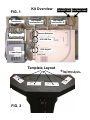
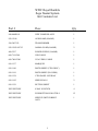
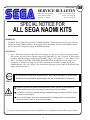
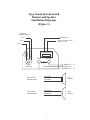
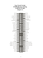
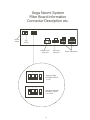
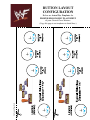
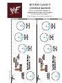
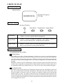
1ST PRINTING DEC. 00
Universal Kit
Kit Installation Instructions
& Service Manual
Switchable FROM High Resolution 31K
TO Standard (Low) Resolution 15.75K.
2 - 4 PLAYER GAME
Kit come with two (2) JVS/JAMMA Interface
Boards for four (4) Player Action.
SEGA ENTERPRISES, INC. USA
MANUAL NO. 999-1117
Warranty
Your new Sega Product is covered for a period of 90 days from the date of shipment. This certifies
that the Printed Circuit Boards, Power Supplies and Monitor are to be free of defects in workmanship or materials under normal operating conditions. This also certifies that all Interactive Control
Assemblies are to be free from defects in workmanship and materials under normal operating conditions. No other product in this machine is hereby covered.
Sellers sole liability in the event a warranted part described above fails shall be, at its option, to
replace or repair the defective part during the warranty period. For Warranty claims, contact your
Sega Distributor.
Should the Seller determine, by inspection that the product was caused by Accident, Misuse, Neglect, Alteration, Improper Repair, Installation or Testing, the warranty offered will be null and void.
Under no circumstances is the Seller responsible for any loss of profits, loss of use, or other damages.
This shall be the exclusive written Warranty of the original purchaser expressed in lieu of all other
warranties expressed or implied. Under no circumstance shall it extend beyond the period of time
listed above.
FIG. 1
Transformer
Audio Board
Kit Overview
JVS/JAMMA
Interface Bd. #1
AC Power Cable Volume/Speaker/
(GRN/WHT/BLK) Coin Meter Cable
JVS/JAMMA
Interface Bd. #2
Service Switches
JVS USB Port
VGA Output
Power Supply
Template Layout
*
*
See Pages v & vii to
copy & cut templates.
FIG. 2
1
WWF Royal Rumble
Sega Naomi System
Kit Contains List
Part #
Desc
840-0040D-01
WWF GAME BD ASSY
1
838-13616
AUDIO AMP (NAOMI)
1
560-5407-UL
TRANSFORMER
1
838-13683-93CV1
JAMMA I/O BD (NAOMI)
2
400-5397
POWER SUPPLY (NAOMI)
1
600-7141-200
USB CABLE
1
600-7009-2500
VGA VIDEO CABLE
1
999-1137
MARQUEE
1
999-1140
INSTR SHEET (CTRL DESC)
1
999-1141
INSTR SHEET (PLAYERS)
1
999-1138
CTRL PANEL OVERLAY
1
999-1142
SIDE DECALS
2
999-1139
BUTTON SHEET
1
XXXXXXXXX
8 WAY JOYSTICK
4
XXXXXXXXX
PUSHBUTTONS FOR CTRLS
12
XXXXXXXXX
SERVICE SWITCH BRKT
ASSY
1
Qty
2
3
Feb 9. 2000
SERVICE BULLETIN
SEGA Service Department
45133 Industrial Drive
Fremont, Ca. 94538
120
http://www.seuservice.com
Phone: 415.701.6580
Fax: 415.701.6594
SPECIAL NOTICE FOR
ALL SEGA NAOMI KITS
PROBLEM:
The SEGA Naomi Game kits are actually ‘JAMMA Dependent’. What this means exactly is they will only
install into existing JAMMA Cabinets. If an operator tries to install these kits into a Non-JAMMA cabinet,
they will first have to bring the wiring up to JAMMA Standards.
SOLUTION:
°
°
Step 1 Disconnect the games original DC Power Supply. You may only use the power supply provided
with your kit. Be sure to set the voltages going to your Game BD to 5.1 and 3.3 volts DC to assure proper
operation ( Measure on Square Connector at Game BD. Yellow = 5vdc / Brown = 3.3vdc / White = Gnd )
Step 2 You MUST USE THE COIN METER SUPPLIED WITH YOUR KIT to assure proper Coin
acceptance. A minimum 18 Gauge wire should be used from the Coin Meter 1 output line on your
JAMMA Harness. The 5vdc ( Yellow ) wire found in the wiring bag of your kit MUST BE USED for the
supply voltage to the meter.
Not following the directions provided herein may cause your game to malfunction.
All electrical work should be performed by the site’s Serviceman or Technician.
In order to prevent an electric shock and short circuit, be sure to turn power off
before performing work or touching the interior parts of the product.
Be careful so as not to damage wirings. Damaged wiring can cause an electric shock
or short circuit accident.
Do not touch places other than those specified. Touching places not specified can
cause an electric shock or short circuit accident.
If you have any questions please contact the SEGA Service Department at the numbers given above.
4
INSTALLATION INSTRUCTIONS
1) First. Remove all access panels from the game. Locate the original game Logic PCB’s & Power
Supply and remove from the Cabinet by first disconnecting all harnesses from the boards. (You need
only to splice in the Main Power (110v AC) into the 3-Pin Connector (GRN/WHT/BLK).)
2) Remove all existing game harnesses (we suggest using New Jamma Harnesses (NOT contained in the
kit) to ensure reliability).
3) Locate the most convenient and open area of the cabinet to mount the WWF Naomi System
Assembly. Make sure this area is free and clear of all cable harnesses and grounds, cable clamps, etc.
(See FIG. 1, inside cover).
Vacuum out or clean bottom of cabinet of dirt & miscellaneous parts (e.g.
screws, loose coins / tokens, etc.).
Remove all exterior decals and repair any cabinet damage. Repaint
cabinet if necessary. Remove the Monitor Plexi or if your game plexi has
Silk-screened artwork, you will need to strip it off.
4) Connect the JAMMA Harnesses to the JVS-JAMMA Interface Boards. Separate the wires from each
other (i.e. Control Panel, Video, Speaker, Power Supply). Run the various harnesses to the part of the
cabinet they go to ensuring they are dressed properly & secured to the cabinet. (See FIG. 4 Pg. iv).
Locate the Volume/Speaker/Coin Meter Cable and connect to your existing Diag. Switch Bracket or
use the new one included with the kit. (See FIG. 3, Pg. iii). Note: If you are using a VGA
Compatible Monitor you can run your VGA Cable directly to the monitor or connect it to your JVS
JAMMA Interface for RGB Conversion to your JAMMA Cables.
5) Remove Marquee from cabinet and cut to fit the new WWF Marquee in place.
WWF uses 1 Lever (Joystick) with 3 Multi-Function Switches (Buttons)
for controls and a Start Button per player. REPLACE old Joysticks &
Buttons with the NEW ones supplied in Kit.
6) First remove all Joystick and Button assemblies from the Control Panel. Remove Lexan and Control
Panel Overlay. Proceed to clean surface of the Control Panel by removing all adhesive and dirt. Fill
in or plug up existing button holes to set up a blank work area for your (1 - 4) templates (See Pages v
& vii, COPY & CUT).
7) Carefully tape template on the Control Panel in configuration of 2 - 4 player; using a Center Punch,
mark your hole centers. With a 1 1/8” Hole - Saw, proceed to drill out holes for the new Control
Panel configuration. Once drilling is complete, clean surface once again eliminating all wood chips
and dust. (See FIG. 2, inside cover).
8) Install the new Control Panel Overlay by carefully peeling off the paper backing and laying down on
the panel. Smooth it out, starting in the center and working your way to the edges (removing all of
the trapped air pockets). If necessary, cut the edges of the overlay excess and fold under panel.
9) Cut out the button and Joystick Holes. Install Joystick and buttons from kit into the Control Panel
and tighten down. Connect all game harness wires to switches and buttons.
5
INSTALLATION INSTRUCTIONS
10) Proceed to place new decals on the sides of the cabinet. Locate a new monitor bezel, if needed, and
replace glass, if required (due scratches). Install Instruction Placard to the back of the Monitor Glass.
NOTE: As a precaution, disconnect the JAMMA Harness from the I/O Boards and turn power on. With a
Multi-Meter, measure the 5v and adjust if necessary to 5.15v DC. Measure the +12, -12 and -5 to ensure the
wires and voltages are in the correct position. Turn power off. Plug in the JAMMA Harness once again to
the I/O Boards. The Attract Mode should appear on the screen.
Adjust the SIZE, CONTRAST, BRIGHTNESS, and COLORS on the
Monitor for optimum appearance. Adjust VERTICAL/HORIZONTAL
Hold to get a stable picture, if required.
Enter DIAGNOSTICS and adjust the Volume Level, test all Buttons &
Joystick for proper operation & wiring. Adjust Pricing. Coin-Up and
test out a game to ensure proper play functions are as they should be.
6
Sega Naomi System Switch
Bracket and Speaker
Installation Diagrams
(Figure 3)
To CN1 of
Amplifier Board
JAMMA Pin 8
Pin 1
Yellow Wire from Extra
Harness (+5v)
Pin 4
Pin 5
WHT/RED
YEL/RED
GRN/RED
_
+
Coin Meter
Test
Service
JAMMA Pin
JAMMA Pin
JAMMA Pin
Volume
GRY/RED
From CN2 of
Amplifier Board
From CN4 of
Amplifier Board
ORG/RED
GRY/BLUE
ORG/BLUE
7
R
1
15
Left
Speaker
Right
Speaker
Sega Naomi System
JAMMA Harness Wiring
(JAMMA I/O BD)
(Figure 4)
Ground
1
A
Ground
Ground
2
B
Ground
+5v (Not Used)
3
C
+5v (Not Used)
+5v (Not Used)
4
D
+5v (Not Used)
(Not Used)
5
E
(Not Used)
+12v (Not Used)
6
F
+12v (Not Used)
Key
7
H
Key
Coin Meter 1
8
J
Coin Meter 2
(Not Used)
9
K
(Not Used)
(Not Used)
10
L
(Not Used)
(Not Used)
11
M
(Not Used)
Video Red
12
N
Video Green
Video Blue
13
P
Video Sync
Video Ground
14
R
Service
Test
15
S
(Not Used)
Coin 1
16
T
Coin 2
1P Start
17
U
2P Start
1P UP
V
2P UP
1P Down
1
8
19
W
2P Down
1P Left
20
X
2P Left
21
Y
2P Right
Attack 1P (1P SW1)
22
Z
Attack 2P (2P SW1)
Grapple 1P (1P SW2)
23
a
Grapple 2P (2P SW2)
Support 1P (1P SW3)
24
b
Support 2P (2P SW3)
(Not Used)
25
c
(Not Used)
(Not Used)
26
d
(Not Used)
Ground
27
e
Ground
Ground
4
28
f
Ground
1P Right
8
Sega Naomi System
Filter Board Information
Connector Description etc.
PSW2 PSW1
Service
Switch
DIPSW1
CN4
CN3
CN2
CN1
Test
Switch
Preamp Level
Audio Out
1
2
3
VGA Level
Video Out
4
Setting for High
Resolution 31KHZ
1 -4 off
1
2
3
Setting for Standard
Resolution 15KHZ
1 on 2-4 off.
9
Power Connectors
10
BUTTON LAYOUT
CONFIGURATION
Below are Actual Size Templates for
PROPER ERGONOMIC PLACEMENT
of your Control Panel Buttons.
Cut Copied Page Only
(Copy this page to cut templates at dotted lines.)
11
THIS PAGE INTENTIONALLY BLANK
12
BUTTON LAYOUT
CONFIGURATION
Below are Actual Size Templates for
PROPER ERGONOMIC PLACEMENT
of your Control Panel Buttons.
Cut Copied Page Only
(Copy this page to cut templates at dotted lines.)
13
THIS PAGE INTENTIONALLY BLANK
14
2. HOW TO PLAY
ON-SCREEN DISPLAY
Monitor Position
HORIZONTAL
Synchronous Frequency
15/31 kHz
CONTROL PANEL
Moving of Wrestlers
Attack Button
A
Grapple Button Support Button
G
S
Attack Button
Enables a wrestler to punch and kick an opponent.
Grapple Button
Enables a wrestler to grapple an opponent. Also enables a wrestler to
throw, or swing onto the ropes, an opponent after grappling.
Support Button
Enables a wrestler to take an action other than attacking and grappling;
that is, to run, mount to a corner, guard, and block.
Available Playing Modes
Two playing modes are available.
Exhibition Mode
This enables you to play a 10-game tournament. You choose a wrestler as yourself and a partner
wrestler, and specify the attacks allowed for the partner; thus you may use your own vital techniques as
well as the various partner attacks in the game. Additional wrestler (from the CPU) may unexpectedly
burst into the ring or you may happen to move to a variety of stages; thus several game effects are
prepared.
Maximum 4 wrestlers can play simultaneously. In this case all the wrestlers other than yourself (as a
wrestler) may be opponents; you may attack one of them together with the rest of them; or any one of
the supporting wrestlers may suddenly betray you. Thus you can enjoy a heated and thrilling game.
Royal Ramble Mode
This enables you to join in a battle royal of maximum 9 persons on the ring. Maximum 4 wrestlers can
play. Any wrestlers fallen from the ring is disqualified. The bottom center part of the monitor screen
shows the number of persons to clear; new wrestlers will continue to appear on the ring until the
number becomes 0 (zero). The number counts down only if the playing wrestlers make the CPU
wrestler fallen from the ring. Winning wrestlers are those who still remain on the ring when the number
is 0 (zero). Furthermore, the high-level S wrestlers may burst into the ring when the number of persons
to clear approaches to 0 (zero).
15
Basic Operations
Attack Button
This button enables you to punch and kick an opponent. Press the button repeatedly to attack
without a break.
Grapple Button
This button enables you to grapple an opponent and then make him staggered or groggy,
throw him or swing him onto the ropes. The button also enables you to throw down or squeeze
a downed opponent. Furthermore, the button enables you to pick up a weapon on the stage
other than the ring.
Support Button
This button enables you to run into the directions set by the lever; and then you may use the
attack and/or grapple buttons to battle. If you are nearby the corner, you may set the lever into
the direction of the post, press the button to mount to the corner, and use the attack and/or
grapple button to battle. Also, you may hold down the button to guard yourself against an
opponent’s offences. In addition, you may press the button in a timely manner against an
opponent’s offence thereby to counterattack. Finally the button enables you to pinfall a downed
opponent.
Button Operations after Grappling
Pressing the Attack Button after Grappling
This action enables you to make an opponent groggy (defenseless). This action, if taken
while setting the lever into any desired direction, enables you to make an opponent staggered
(also, defenseless) into the set direction. Press the attack button again to punch or kick the
groggy or staggered opponent while the grapple button to throw. In these cases, the opponent
cannot counterattack.
Pressing the Grapple Button after Grappling
This action, if taken while setting the lever into any of the neutral/upper/lower/left/right
directions, enables you to throw a grappled opponent even if grappled in the rear.
Pressing the Support Button after Grappling
This action enables you to swing or hammer-throw an opponent onto the ropes. After swinging,
press the attack or grapple button to battle. Alternately set the lever into any desired directions
to swing the opponent into the set direction. Set it into a slant direction to swing the opponent
to the corner in the set direction and thus make the opponent corner-down. Grapple, and then
punch, kick, or throw the corner-downed opponent.
NOTE: When grappled you can counterattack by pressing the button same as the one
opponent is pressing.
16
Partner Attacks (in Exhibition Mode)
According to a WWF rule, you specify your own wrestler and its partner. Attacks by the
partner are called partner attacks. You also specify any one out of the three partner attacks;
Type A, Type B, and Type C. You can use a partner attack by pressing any two buttons
simultaneously.
Independent Partner Attacks
Only a partner wrestler attacks an opponent. These attacks include a dashing punch/kick,
continuous attack, weapon attack, dived attack from a corner, and vital technique.
Two-Platoon Attacks
You (as a wrestler) may try to grapple (or punch or kick) an opponent. After successfully
grappling, you and the partner cooperate to do the two-platoon attacks.
Supporting Partner Attacks
The partner does not attack but provides various supporting actions. Such actions include
giving of a weapon, increasing of your special gauge number, decreasing of an opponent’s
special gauge number, making an opponent groggy, escaping from a pitfall, etc.
NOTE: The Partner Attack are not usable in a wire-netting stage.
“S” Special Gauge Icon
Special gauge icon is located below a power gauge icon and indicates a “S” number. Saving
and increasing of the “S” number enables you to use high-grade (HG) attacks, vital techniques,
etc. You can use these features by pressing the three buttons simultaneously.
HG Attacks (decreasing of “S” number: 1 each)
HG attack is more powerful than a usual one. Such powerful attacks include a dashing attack,
attack from a corner, downward attack, etc. and thus are usable in various situations.
Vital Technique (decreasing of “S” number: 3 each)
Every wrestler is given one vital technique (and two lock techniques). Applicable situation
of these techniques varies from wrestler to wrestler. One technique is only applicable in a
standing position, another for a downed opponent, and the other from a corner. Each vital
technique can seriously damage an opponent and even KO a powerless opponent.
Escaping from a Pinch (decreasing of “S” number: 1 each)
You can escape from a pinch such as a pinfall, groggy state, downed state, grappled state, etc.
17
Special Operations with Royal Ramble Mode
The royal ramble mode has a rule of making an opponent fallen from the ring. This needs to
specify special operations that an exhibition mode does not support.
How to make an opponent fallen from the ring
To grapple an opponent nearby the ropes and hammer-throw him into outside the ring:
Grapple an opponent nearby the ropes, set the lever into outside the ring, and press the support
button.
NOTE: In an exhibition mode this is to hammer-throw into inside the ring.
To make an opponent stagger into outside the ring:
Grapple an opponent nearby the ropes, set the lever into outside the ring, and press the attack
button.
NOTE: In an exhibition mode this is to make an opponent bound against the ropes and stagger.
To punch or kick an opponent leaning against the ropes:
If attacked nearby the ropes, an opponent may lean against them and be in a downed state.
Punch or kick such an opponent and then you can make him fallen from the ring.
To raise up and stagger a downed opponent:
Press the grapple button for a downed opponent to raise up and stagger. You can stagger him
into any desired directions; if you set the lever into the direction outside the ring, therefore,
you can make him fallen from the ring.
NOTE:
An opponent having the power may grasp the ropes and thus resist against falling. If this is
the case, press the attack button to stomp the opponent. Grasping the ropes to resist against
falling for a prolonged time and loosing the power will result in falling from the ring. Get
back to the ring by operating the lever. Also, you can return to the ring immediately when
pressing the three buttons simultaneously with decreasing “S” number by 1.
Referee Knockout
You can attack a referee only with a weapon. State of the Referee Knocked Out occurs when
you have knocked out the referee twice. In this state the partner attacks can be repeated
without a break while usually they can be repeated only with a break. Also in this state you
are not counted down even in a pinfall.
Win and Loss Rule (in Exhibition Mode)
Pinfall
Press the support button for a downed opponent, which starts counting for a pinfall. Alternately,
throw down an opponent and press the support button, which also starts counting for a pinfall.
In either case you will be a winner if the opponent is counted out to 3. The pinned wrestler
may cancel a pinfall by operating the lever. (Turn the lever for an easier cancellation.) Also,
you can quickly cancel a pinfall by pressing the three buttons simultaneously with decreasing
“S” number by 1.
KO
Exercise a vital technique for a low-power opponent to reduce its power to zero. Then you
will be a winner.
Judgment
When the game is ended in a tie, a winner is decided by judging the remaining power etc.
18
3. TEST MODE
A. SYSTEM MENU
When you have changed the settings of the SYSTEM ASSIGNMENTS, COIN
ASSIGNMENTS, and GAME ASSIGNMENTS (on the GAME TEST
MODE screen), be sure to select the EXIT from the SYSTEM MENU screen
and press the test button to exit from a test mode. This action can store the
new settings in the IC on the board. Disconnecting the power when in a test
mode may fail to store the new settings and eventually the present settings
may remain effective.
This game allows you to set the number of players to 2 or 4. Correctly set it
according to the number of the input cables connected to the cabinet. Failure
to do so may malfunction the game.
This test mode mainly allows the IC Board to be checked for accurate functioning, monitor
color to be adjusted as well as COIN ASSIGNMENTS and GAME ASSIGNMENTS to be
adjusted.
1) After turning power on, press the TEST Button to have the following SYSTEM MENU
displayed.
SYSTEM MENU
RAM TEST
JVS TEST
SOUND TEST
C.R.T. TEST
SYSTEM ASSIGNMENTS
COIN ASSIGNMENTS
BOOKKEEPING
BACKUP DATA CLEAR
CLOCK SETTING
ROM BOARD TEST
GAME TEST MODE
[XXXXXXX
]
-> EXIT
SELECT WITH SERVICE BUTTON
AND
PRESS TEST BUTTON
In the SYSTEM ASSIGNMENTS.
CABINET TYPE is set to 2 PLAYER(S) or 4 PLAYER(S),
and MONITOR TYPE is set to HORIZONTAL.
The other items are initially set to as follows:
ADVERTISE SOUND ON
SERVICE TYPE
COMMON
COIN ASSIGNMENTS initial settings as follows:
COIN CHUTE TYPE: COMMON
COIN/CREDIT SETTING: #1
COIN CHUTE #1 (#2): 1 COIN 1 CREDIT
SEQUENCE SETTING of COIN ASSIGNMENTS functions as follows:
SEQUENCE 1: Number of credits required for game start
(initial value = 1 CREDIT).
SEQUENCE 2: Number of credits required for CONTINUE
(initial value = 1 CREDIT).
SEQUENCE 3~8: NOT USED.
MEANING OF DISPLAY IN BOOKKEEPING 2/2
P1 (~P4) SEQ 1: Play frequency of Player 1
(~Player 4).
P1 (~P4) SEQ 2: Frequency CONTINUE by Player 1
(~Player 4).
P1 (~P4) SEQ 3~8: NO USE.
CAUTION FOR SETTING
When you have set the SERVICE TYPE and the COIN CHUTE TYPE to INDIVIDUAL,
the players 1 and 2 share the credit of COIN 1 and SERVICE 1 while the players 3 and 4
share the credit of COIN 3 and SERVICE 3.
If you want to use the coin chute for COIN 2 (4) and the service button for SERVICE 2 (4),
therefore, set the SERVICE TYPE and the COIN CHUTE TYPE to COMMON.
19
2) Press the SERVICE Button to move the arrow. Bring the arrow to the desired item and
press the TEST Button.
3) Press the TEST Button in the GAME TEST MODE to display the GAME TEST MODE
peculiar to this game. See the next page onward.
4) Upon finishing the test, bring the arrow to EXIT and press the TEST Button to return
to the Game mode.
For detailed explanations as regards the SYSTEM TEST MODE, refer to NAOMI
SERVICE MANUAL (420-6455-01).
B. GAME TEST MODE
Move the -> mark to GAME TEST MODE item on the SYSTEM MENU screen, and
press the TEST Button. The game-specific GAME TEST MODE screen appears.
<<GAME TEST MODE>>
INPUT TEST
GAME ASSIGNMENTS
BOOKKEEPING
BACKUP DATA CLEAR
1
2
3
4
-> EXIT
SELECT WITH SERVICE BUTTON
AND
PRESS TEST BUTTON
GAME TEST MODE screen
Pressing the SERVICE Button can move the -> mark. Move the -> mark to a desired
item, and press the TEST Button.
After testing, select the EXIT and press the TEST Button. The SYSTEM MENU screen
reappears.
20
1 INPUT TEST
This screen tests the input devices.
Press each button and make sure that the corresponding OFF
disappears and the ON appears.
<<INPUT TEST>>
TEST BUTTON
[OFF]
SERVICE BUTTON [OFF]
1P
[OFF]
[OFF]
[OFF]
[OFF]
[0][0][0]
[0] [0]
[0][0][0]
START
ATTACK
GRAPPLE
SUPPORT
STICK
TEST ............... Changes to ON when pressing the TEST
BUTTON.
2P
[OFF]
[OFF]
[OFF]
[OFF]
[0][0][0]
[0] [0]
[0][0][0]
PRESS SERVICE BUTTON
AND
TEST BUTTON TO EXIT
SERVICE ........ Changes to ON when pressing the SERVICE
BUTTON.
START ............ Changes to ON when pressing the START
BUTTON.
ATTACK ......... Changes to ON when pressing the ATTACK
BUTTON.
GRAPPLE ..... Changes to ON when pressing the
GRAPPLE BUTTON.
SUPPORT ..... Changes to ON when pressing the
SUPPORT BUTTON.
LEVER ........... From 0 to 1 on the set direction.
000
0 0
000
If set to the upper
right direction.
001
0 0
000
If the CABINET TYPE is set to 4 PLAYER(S) on the SYSTEM ASSIGNMENTS screen,
the 3P and 4P columns, are displayed.
2 GAME ASSIGNMENTS
This screen sets the difficulty level and playing time. Press the SERVICE Button to
move to a desired item, and press the TEST Button to select a new setting.
DIFFICULTY ......... 5 levels are selectable.
<< GAME ASSIGNMENTS >>
DIFFICULTY
TIME LIMIT
RESET
[NORMAL]
[180]
EXIT
TIME LIMIT .......... Playing time in minute for a game.
60, 120, or 180 is selectable.
RESET .................... Initial settings are recovered.
Initial settings are:
SELECT WITH SERVICE BUTTON
AND
PRESS TEST BUTTON
DIFFICULTY ...... NORMAL
TIME LIMIT ...... 180
21
3 BOOKKEEPING
This screen displays the playing time data.
<< BOOKKEEPING >> PAGE 1/2
PLAY TIME
AVERAGE TIME
LONGEST TIME
SHORTEST TIME
-D-H-M-S
-M-S
-M-S
-M-S
PLAY TIME ................. Actual playing time data (For 2P
game, playing time periods are not
overlapped.)
Press the TEST Button to open the next PAGE 2/2
screen.
PRESS TEST BUTTON TO CONTINUE
<< BOOKKEEPING >> PAGE 2/2
0M00S ~ 0M29S
0M30S ~ 0M59S
1M00S ~ 1M29S
1M30S ~ 1M59S
2M00S ~ 2M29S
2M30S ~ 2M59S
3M00S ~ 3M29S
3M30S ~ 3M59S
4M00S ~ 4M29S
4M30S ~ 4M59S
5M00S ~ 5M29S
5M30S ~ 5M59S
6M00S ~ 6M29S
6M30S ~ 6M59S
7M00S ~ 7M29S
7M30S ~ 7M59S
8M00S ~ 8M29S
8M30S ~ 8M59S
9M00S ~ 9M29S
9M30S ~ 9M59S
OVER 10M00S
-
This screen indicates the by-playtime play frequency.
Press the TEST Button to return to the GAME TEST MODE
screen.
PRESS TEST BUTTON TO EXIT
4 BACKUP DATA CLEAR
This screen clears the high scores and the bookkeeping data.
<< BACKUP DATA CLEAR >>
YES (CLEAR)
-> NO (CANCEL)
SELECT WITH SERVICE BUTTON
AND PRESS TEST BUTTON
Press the SERVICE Button to move the -> mark to YES
item, and press the TEST Button. When the system
completes clearing, the COMPLETED message appears on
the screen. Press the TEST Button to return to the GAME
TEST MODE screen. Press the SERVICE Button to move
the -> mark to NO item, and press the TEST Button. The
system does not execute clearing, but returns to the GAME
TEST MODE screen.
22
0V
50
120V
838-13616
17V
0V
0V
17V
560-5407
AUDIO POWER AMP 2CH
JST VH 4P
P C
1 2 3 4 5 6
31
50
50
41
51
50
5k pot
71
50
30
10
50
50
10
30
[Extra] [GD ROM DRIVE]
72
92
120 Vac Input
TRANSFORMER
80
91
1
2
3
WHITE(U/P)
P C
3
1
Phono
plugs
2
JST VL
IN
1
6
838-13683-91
To PIN 8
of Jamma
CN6
50 50 10 10 30 30
GND
GND
P C
+3.3V
+5V
GND
GND
GND
P C
+3.3V
+5V
+12V
OUT
To Extra
Yellow Wire
MUST BE SET TO "IN"
TO USE INPUTS ON CN3
COIN COUNTER
JP1
SW REGU FOR JVS
VCC
VCC
NC
1P SW6
1P SW7
1P SW8
NC
2P SW6
2P SW7
2P SW8
NC
NC
GND
GND
400-5397
1
2
3
4
5
6
7
8
9
10
11
12
13
14
JST VL
SPEAKER OUTPUTS
600-7141-050
10
20
30
40
50
60
70
80
A
B
C
D
E
JAMMA CONNECTIONS USED ARE:
° VIDEO OUT
° SWITCH INPUTS
° SWITCH GROUND RETURNS
° COIN COUNTER OUTPUT
600-7155
600-6743-050
NOTE: THERE ARE TO BE NO
CONNECTIONS MADE TO THE
JAMMA INTERFACE OTHER THAN
THE ABOVE FOREMENTIONED.
NAOMI KIT UNIVERSAL
WIRING DIAGRAM (1/1)