Download QSC ABX Comparator User manual


Transcript
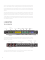
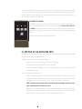
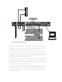
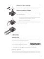
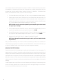
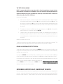
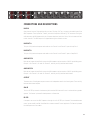
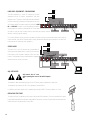
ABX Comparator
USER MANUAL
ON
POWER
D ATA
UNIT A
X
UNIT B
ENTER
C A L I B R AT E
TRIAL
REVIEW
SCROLL
ABX1
ABX COMPARATOR
RC
▼
ABX Comparator
Double-blind listening test switcher
1
2
ABX Listening Test Comparator
I. INTRODUCTION
The ABX Comparator is a signal routing and measuring device that permits simple and accurate comparative
listening tests of two or more power amplifiers or even line-level audio components. Using advanced
microcontrollers, the ABX Comparator’s features and functions allow you to quickly set up and conduct sessions
of critical listening test trials for performance evaluations.
Key features include:
•
A built-in test tone generator and digital AC voltmeter for fast calibration of amplifier levels.
•
High-speed relays for fast switching between amplifiers under test.
•
A single pair of speaker outputs, for true accuracy.
WHY USE AN ABX COMPARATOR?
Comparison tests between amplifiers are often plagued with these unintended but very real inconsistencies that
lead to inaccurate auditions:
Unequal input sensitivities This leads to one amplifier being louder than another. Even experienced
critical listeners often confuse differences in volume with differences in audio quality.
Different speakers used with each amplifier The difference in frequency response between two
loudspeakers, even of identical models, can often be several dB. This can easily mask differences in
amplifier audio quality.
Slow switching between amplifiers Your “audio memory” is short-lived. You won’t catch small sonic
differences between amplifiers unless switching between them is quiet and fast (under 50 ms).
Unconscious bias Even when you try to be truly unbiased, your unconscious mind often leads your
conscious mind subliminally to bad conclusions, as in a “This is a Brand A amp, and this is a Brand B—
which sounds better to you?” type of test. The solution is to have the listener completely unaware of
which amp is which, even in the inital audition. This is called double-blind testing, and it’s the only
way to get a truly unbiased result.
The ABX Comparator has been specifically designed to eliminate all these errors.
THE ABX TESTING PROCEDURE
The letters “ABX” describe the listening factors used in double-blind testing of two amps. One amp is “A” and
the other is “B,” and the two have been set up so that they put out precisely the same output levels. “X” designates
the unknown factor—is it A or is it B? Thus, every time the ABX Comparator randomly selects “X,” which could
be either A or B, the person judging the amps will compare it to amp A and amp B (all the while paying attention
to detect audible differences between the two). The challenge then is to identify X. And this is truly “doubleblind” testing, so the listening judge doesn’t even know which amp being tested is A and which is B, but must
nevertheless decide whether X is A or B.
3
One trial is not enough; even flipping a coin to decide which amp is X would yield the right result about half the
time. No, it takes repeated trials, with X randomly selected each time, to get a statistically significant test. If
the listening judge answers correctly in only about 50% of the trials, he or she didn’t hear any audible difference
between the amps. But if far more than 50% of the answers are correct, the listener clearly discerned some audible
difference.
Notice that the decision made in each trial isn’t “which amp sounds better?” Instead, the goal is to identify whether
the amps sound totally alike or different; deciding which is better sounding is a job best left for later. You can’t
judge whether one amp sounds better than another unless you determine that they actually sound different!
The ABX Comparator not only automatically and randomly selects the amplifiers, but also tracks the choices the
listening judge makes in each trial. After a sequence of trials, the ABX will report how many trials and how many
correct answers the judge made.
II. DESCRIPTION
THE ABX COMPARATOR
Calibration
voltmeter display
Power switch
LCD display
UNIT A button
ON
D ATA
POWER
CALIBRATE button
UNIT X button UNIT B button ENTER button
UNIT A
X
UNIT B
ENTER
C A L I B R AT E
TRIAL
REVIEW
SCROLL
TRIAL button
ABX1
RC
ABX COMPARATOR
REVIEW button SCROLL button
Infrared sensor
(for remote)
Front panel
The front panel features a power switch, a digital voltmeter display (for calibration), an alphanumeric LCD display,
eight input and control buttons, and a female 8-pin DIN connector. During operation, menus, instructions, and
data appear on the LCD display.
Binding post signal terminals
CH1
B
A
M
P
B
INPUT
CH1
OUTPUT
CH2
CH2—LINE OUT—CH1
B
A
INPUT
CH2
RS232 to optional
computer
“Combo”signal connectors
A
M
P
A
CH2—LINE IN—CH1
P 1=G
P 2=+
P 3=-
Rear panel
CH2—LINE OUT—CH1
A
RS232
QSC AUDIO
PRODUCTS INC.
SLAVE
AC power
connection
REPLACE
FUSE WITH
SAME TYPE.
SEE USER'S
MANUAL FOR
RATING.
MADE IN
U.S.A.
RS232 output
to slave ABX
The rear panel has input and output connectors, a 9-pin RS-232 port for connecting to an optional computer,
and an additional RS-232 port for slaving one or more additional ABX units.
4
To route the audio signals, the ABX Comparator uses passive circuitry comprising relay switches controlled by
the internal microcontroller. To avoid any possible coloration of the audio and to allow bidirectional signal flow
(because testing of line-level devices uses a different hookup configuration than testing amplifiers does), no
active circuitry is used in the test signal path.
THE REMOTE CONTROL
The handheld remote control, shown at left, communicates with the ABX via encoded infrared
light. The remote duplicates four of the ABX’s front panel buttons: UNIT A, UNIT X, UNIT B,
and ENTER. Although the listener could enter his or her choices for each trial using the front
A
X
B
panel buttons, it’s probably much more convenient to use the remote from a comfortable listening
position.
Enter
The ABX can also operate without the remote control.
III. SETTING UP AN AMPLIFIER TEST
The diagram on the following page shows how to wire the ABX Comparator and the other components needed
for a listening test of two 2-channel amplifiers.
In addition to the ABX unit, you will need the following:
•
A high-quality line-level stereo signal source, such as a CD player.
•
Two 2-channel amplifiers, designated A and B, to be tested.
•
One pair of high-quality speakers, with a power handling capacity suitable for the amplifiers and
intended listening level.
You will also need the following cables:
•
A pair of shielded audio cables for connecting the signal source outputs to the ABX line-level inputs.
One end of each cable must have a connector suitable for the source device, and the other end must
have either a male 3-pin XLR or a male ¼-inch (6.3 mm) TRS connector for the ABX unit.
NOTE: For best results, the signal source should have balanced outputs, and all line-level
signal cabling should be balanced as well.
•
Another pair of shielded audio cables for connecting the ABX to Amplifier A’s inputs. One end of each
cable must have a connector suitable for the amplifier’s inputs, and the other end must have either
a male 3-pin XLR or a male ¼-inch (6.3 mm) TRS connector for the ABX unit.
5
Speakers
Speakers
CD PLAYER
CH1
B
A
M
P
B
INPUT
CH1
OUTPUT
CH2
CH2
CH2—LINE OUT—CH1
A
M
P
A
CH2—LINE IN—CH1
B
A
INPUT
CH2—LINE OUT—CH1
A
RS232
QSC AUDIO
PRODUCTS INC.
SLAVE
P 1=G
P 2=+
P 3=-
REPLACE
FUSE WITH
SAME TYPE.
SEE USER'S
MANUAL FOR
RATING.
MADE IN
U.S.A.
2
RS
32
k
lin
(o p
n
tio
al)
CH1 out
CH2 out
AMP A
CH 2 in CH 1 in
CH1 out
CH2 out
AMP B
CH 2 in CH 1 in
Computer (optional)
ABX cabling setup for testing amplifiers
•
Another pair of shielded audio cables for connecting the ABX to Amplifier B’s inputs. One end of each
cable must have a connector suitable for the amplifier’s inputs, and the other end must have either
a male 3-pin XLR or a male ¼-inch (6.3 mm) TRS connector for the ABX unit.
•
A pair of two-conductor speaker cables for connecting Amplifier A’s outputs to the ABX. Prepare one
end of each cable so it is suitable for the amplifier’s outputs, with either a connector or stripped wire
ends, as required. The other end must have either a dual banana plug or stripped wire ends, suitable
for connecting to the ABX’s binding posts labeled “AMP A.”
•
Another pair of two-conductor speaker cables for connecting Amplifier B’s outputs to the ABX. Prepare
one end of each cable so it is suitable for the amplifier’s outputs, with either a connector or stripped
wire ends, as required. The other end must have either a dual banana plug or stripped wire ends, suitable
for connecting to the ABX’s binding posts labeled “AMP B.”
•
One pair of two-conductor speaker cables for connecting the ABX’s binding post outputs, labeled “AMP
X,” to the speakers. One end must have either a dual banana plug or stripped wire ends, suitable for
connecting to the ABX’s binding posts, and the other end must be suitable for connecting to the
speakers’ input connection.
6
CONNECTING TO “COMBO” CONNECTORS
The six Neutrik “Combo™” connectors accept either 3-pin male XLR or ¼-inch (6.3 mm) male
TRS connectors. Pin 2 and tip are +; pin 3 and ring are -; pin 1 and sleeve are shield.
CONNECTING TO BINDING POST TERMINALS
When setting up the ABX for amp testing, it is vitally important for safety reasons that you
connect the cabling between the amplifier outputs, the ABX, and the speakers correctly. Use
only fully insulated stranded wire.
1.
First, strip back the insulation no more than ½ inch (13 mm).
2.
Insert the wire fully into the opening so that no part of the conductor is exposed,
then tighten the barrel. Use a coin to tighten it, if necessary.
3.
Alternately, you can use dual banana plugs.
When setting up a test between two line-level devices, these binding post connectors serve
as the return from the devices under test and the send to the amplifier. See the appendix for
more details on testing line-level devices.
IV. OPERATION
TURNING THE ABX ON
Connect the ABX to AC power: 100, 120, or 220–240 volts. The internal power supply automatically adjusts to
the AC line voltage. Turn on the unit using the front panel switch.
In the first few seconds after being turned on, the ABX’s LCD display
will first display the unit model and then its firmware version information. Then it will ask you for the type of test you wish to do.
For a power amp test, press the A button, then proceed to the calibration procedure below.
For a test of line-level devices, press the B button and see the appendix for the test procedure.
PRE-SESSION: CALIBRATION
The ABX will automatically enter calibration mode after you select a power amp test from the “Select Test Type”
screen. You can also force the ABX into calibration mode by pressing the CALIBRATE button on the front panel.
7
In the calibration mode, the ABX Comparator will produce a 1 volt RMS, 1 kHz tone and send it to both channels
of both amplifiers in place of the audio signal input. At the same time, the digital voltmeter display will show
the output level from each amplifier channel, starting with Channel 1 of Amplifier A. In Calibration Mode,
however, the loudspeakers are muted, so you won’t hear the test signal.
1.
Turn off the audio source—the CD player, DAT, et al—until you complete the calibration process.
2.
Adjust the gain control of Channel 1 of Amplifier A until the voltmeter reads a reasonable voltage. The
ideal voltage will depend on the amps under test and the loudspeakers used for the listening test. For
example, a more efficient pair of speakers won’t require as much gain or power as a less efficient pair
will. For most systems a good starting point would be 20.0 to 40.0 volts.
NOTE: For better accuracy and easier adjustability, set the amplifier gain controls toward
the upper range of settings.
3.
Once you have the gain set for Amplifier A, Channel 1, take note of the voltmeter reading. You’ll want
to match this voltage with the three other amplifier channels. Press ENTER.
4.
Now the ABX prompts you to set the gain for Amplifier A, Channel 2. Adjust the channel’s gain control
until you get the same voltmeter reading as with Channel 1, within 0.1 volt. Press ENTER.
5.
Repeat step 3 for Amplifier B, Channel 1, and again for Amplifier B, Channel 2.
NOTE: If one of the amplifiers under test has no gain controls, you’ll have to match the other
amp to that one.
After you complete calibrating all four channels, the ABX will automatically proceed to the trial mode, which
is the session of actual listening trials. (However, if you are unsatisfied with or unsure about the calibration, you
can press the CALIBRATE button on the front panel to go back and repeat the procedure.)
READYING THE TEST SESSION
Start the test session with the listening judge in a comfortable listening position in front of the speakers. For
program material, use a familiar, high-quality recording, although there are many preferences and schools of
thought on what constitutes suitable music for audio performance evaluations. Acoustic music is often good for
revealing distortions in an amplifier, while heavy metal might tend to mask them. Synthesized bass might highlight
differences in the low end. Clean, up-front vocals that sound harsh through one amp indicate probable midrange
problems, particularly if they don’t sound harsh through the other amp. Use your own judgment in selecting the
recording.
The ABX Comparator can run up to 25 trials in a session. Afterwards, the LCD display will show how many correct
answers the listening judge entered, out of how many trials, and the resulting percentage of correct answers.
You can also review the results of each trial in the session.
8
THE TEST SESSION BEGINS
NOTE: To preserve objectivity in the test, don’t tell the listening judge before or during the trials
which amplifier is A and which is B. Otherwise, if he or she has even a slight prejudice toward or
against one amp, they may try to pay attention to “does Amp X sound like Brand Z” instead of to
whether the amps sound alike or different.
Instruct the listening judge:
1.
Each trial starts with the X, or unknown, amplifier, which could be either Amp A or Amp B. Compare
its sound with that of Amp A, by pressing the A button, and to Amp B, by pressing the B button. You
can switch to X by pressing the X button. You may freely switch back and forth among Amp A, Amp
B, and Amp X as much as you’d like before you enter your choice. Listen carefully. Does X sound like
A, or like B?
2.
To register your choice with the ABX Comparator, press the button—either A or B—of the amplifier
that you believe is X, the unknown. Then press ENTER.
3.
The ABX will not tell you if you were right or wrong; instead, it will immediately go on to the next trial,
randomly selecting which amp will now be X. In the this new trial, X might be the same ampilfier as
in the preceding trial, or it might be the other amp. Don’t let your previous evaluations influence your
current one.
Repeat this procedure for each trial.
The ABX unit switches only the amplifier outputs to the speakers, and not the audio signal to the amps. This
prevents the listener from getting visual cues from the amplifiers’ front panel LEDs or meters.
ENDING AND REVIEWING THE TEST SESSION
You can end the test session at any time by pressing the REVIEW button on the front panel of the ABX, or you
can just have the evaluator perform all 25 trials. Remember, the more trials you conduct, the more statistically
significant your results will be.
If you press the REVIEW button, the ABX will ask you whether you want to enter review mode. Press A if you
do, but if you want to continue with more listening trials, press B, then go ahead and do some more trials.
In review mode, the LCD display will show how many times the listening evaluator identified X correctly, out
of how many trials, and the percentage. To view the result of each trial,
press the SCROLL button. Each time you press the SCROLL button, the
display will step to the result of the next trial.
OBTAINING STATISTICALLY SIGNIFICANT RESULTS
Given only two possibilities in each trial, a random selection of A and B, such as each selection being based on
coin toss—or even just selecting the same one every time—would tend to yield correct results about 50% of
the time. In a small sample, i.e., a small number of trials, the actual results may be wildly different from 50%,
9
but over an increasing number of trials will almost certainly tend to approach 50%. For example, the chances
of a coin coming up heads on two successive tosses is 1 in 4; on three successive tosses, 1 in 8; on four successive
tosses, 1 in 16. Getting tosses of heads ten times in a row is likely only one time in 1024. In other words, large
samples tend to smooth out the aberrations of randomness that occur.
Therefore, not only do you need to conduct a fair number of trials in a session, but the results have to be
substantially better than 50% to mean that there is an audible difference between the units under test.
The very minimum number of trials you should do in a session is ten. Out of ten trials, if the listener chose the
correct amplifier seven times, he or she might have heard some difference between the two, but it’s really too
inconclusive. Eight correct choices would indicate a probable audible difference between the amplifiers, with
about a 95% level of confidence. Nine out of ten would be an even stronger indication. Ten out of ten would
almost certainly indicate the listener heard some sonic differences between the amps, since there’s only a 1 in
1024 chance it could randomly.
What we’re really after in these statistics is a high degree of confidence that the results show real conditions
and not random occurrences. For example, a series of 25 trials has 33,554,432 possible combinations of right/
wrong answers, ranging from 0 correct/25 wrong, up to 25 correct/0 wrong. There are 5,200,300 possible
combinations of 12 correct/13 wrong, and an identical number of possible 13 correct/12 wrong. There is only
one combination of 25 correct/0 wrong, and while it is possible that a random sequence of responses could be
right 25 out of 25 times, there is only a 1 in 33,554,432 chance of it happening. Therefore, we can say that there
is a 33,554,431/33,554,432 (99.999997%) chance of it not happening; that would also be our level of confidence
in the results: 99.999997%.
We won’t be quite as picky with the listening tests; a 95% minimum level of confidence will be good enough.
That is, there should be less than a 5% chance that the results can be attributable to chance.
# of trials
10
11
12
13
14
15
16
17
18
19
20
21
22
23
24
25
Minimum #
correct
8
8
9
9
10
11
11
12
12
13
14
14
15
15
16
17
The table on this page lists a recommended range of trials, and the minimum number of correct responses
necessary to reach a 95% or better level of confidence.
As you increase the number of trials, your data becomes more dependable. Notice that you need 8 of 10 but only
17 of 25 to get the same degree of confidence.
So, if your listener correctly “guesses” the identity of “X” at least the minimum number of times in the session
of trials, you can confidently estimate that there is an audible difference between the amplifiers under test. Of
course, that may mean that one amp sounds worse than the other—maybe even the amp you favor, if you do
have an interest in one brand or model over the other. On the other hand, if the listener gets fewer than the
minimum number correct, it doesn’t necessarily mean that the amps are audibly indistinguishable, although they
may be. It more accurately means only that you can’t confidently say there’s an audible difference.
It’s not a good idea to try more than 25 trials in the same sitting with the same listener. After a while, listener
fatigue sets in and it gets harder for him or her to concentrate and judge the sound quality.
10
CH1
B
A
M
P
B
INPUT
CH1
OUTPUT
CH2
CH2—LINE OUT—CH1
B
A
INPUT
CH2
A
M
P
A
CH2—LINE IN—CH1
CH2—LINE OUT—CH1
A
P 1=G
P 2=+
P 3=-
RS232
QSC AUDIO
PRODUCTS INC.
SLAVE
REPLACE
FUSE WITH
SAME TYPE.
SEE USER'S
MANUAL FOR
RATING.
MADE IN
U.S.A.
CONNECTORS AND DESCRIPTIONS
LINE IN
A two-channel source of high-quality audio, such as a CD player, DAT etc., connects to the audio inputs of the
ABX Comparator. These inputs use “Combo” jacks which accept both XLR and ¼" TRS connectors. During the
calibration step, the ABX bypasses this pair of inputs and replaces it with the 1 Vrms, 1 kHz sine wave oscillator
to both channels. The ABX output is also bypassed during the calibration routine.
LINE OUT A
This pair of fully-balanced outputs sends audio to the Channel 1 and Channel 2 inputs of amplifier A.
LINE OUT B
This pair of fully-balanced outputs sends audio to the Channel 1 and Channel 2 inputs of amplifier B.
AMP INPUT A
Both channel outputs of amplifier A return to the ABX comparator at the two pairs of AMP A input binding posts.
One pair is for Channel 1, the other for Channel 2, and they are fully balanced and isolated.
AMP INPUT A
Both channel outputs of amplifier A return to the ABX comparator at the two pairs of AMP A input binding posts.
One pair is for Channel 1, the other for Channel 2, and they are fully balanced and isolated.
OUTPUT
These two pairs of binding post outputs connect to the loudspeakers used in the listening tests. These are fully
balanced and isolated outputs.
SLAVE
This is an RS-232 port used to simultaneously drive another ABX slave unit for use in active multi-way speaker
systems. This feature is planned for development at a future date.
RS-232
A computer can control the ABX Comparator through the unit’s RS-232 port. Instead of the standard remote
control, you can use Microsoft® Visual Basic® to create a custom PC control application. This feature is planned
for development at a future date.
11
Speakers
LINE-LEVEL EQUIPMENT COMPARISONS
The ABX Comparator is useful for comparing line-level
Speakers
equipment such as CD players, preamplifiers, and other
equipment, too. The setup is a little different and varied with
CH1 out
CH2 out
CH 2 in CH 1 in
this form of testing. For example, testing signal sources such
as CD players and DAT recorders requires only the ABX’s LINE
IN and LINE OUT connectors, but connected with the device
AMP
CH1
B
A
M
P
INPUT
CH1
CH2—LINE OUT—CH1
B
A
OUTPUT
CH2
B
INPUT
CH2
A
M
P
A
CH2—LINE IN—CH1
CH2—LINE OUT—CH1
A
RS232
QSC AUDIO
PRODUCTS INC.
SLAVE
P 1=G
P 2=+
P 3=-
REPLACE
FUSE WITH
SAME TYPE.
SEE USER'S
MANUAL FOR
RATING.
MADE IN
U.S.A.
2
RS
32
inputs going to the connectors labeled LINE OUT. Use a setup
lin
k(
A
na
tio
CD PLAYER, DAT, ETC.
l)
CD PLAYER, DAT, ETC.
op
B
as shown at right. Be sure to match levels as accurately as possible, and use
identical listening program material.
For line-level devices such as processors, preamps, and other units having inputs and outputs, use a setup as
shown at below right. While Calibrate mode is largely intended for amplifier gain alignment, it can serve as a
Computer (optional)
tone generator for matching other equipment.
Speakers
SLEEP MODE
Speakers
The useful life of the LCD display may be extended by
enabling the sleep mode function. Jumper J103 on the main
CH1 out
CH2 out
PCB enables (J103 shorted) or disables (J103 open) this
function. Sleep mode is factory enabled and will engage 60
minutes after the last key is pressed.
CH1
B
A
M
P
B
AMP
INPUT
CH1
OUTPUT
CH2
CH 2 in CH 1 in
CH2—LINE OUT—CH1
B
A
INPUT
CH2
A
M
P
A
CD PLAYER, DAT, ETC.
CH2—LINE IN—CH1
CH2—LINE OUT—CH1
A
RS232
QSC AUDIO
PRODUCTS INC.
SLAVE
P 1=G
P 2=+
P 3=-
REPLACE
FUSE WITH
SAME TYPE.
SEE USER'S
MANUAL FOR
RATING.
MADE IN
U.S.A.
2
RS
32
lin
CH1
A
CH2
IN
CH1
OUT
l)
LINE-LEVEL DEVICE
OUT
na
tio
IN
LINE-LEVEL DEVICE
op
CH2
k(
B
ADJUSTMENTS
Disconnect the AC cord
before opening the cover of the ABX Comparator.
The upward or downward viewing angle of the LCD display may be adjusted by trimpot XXX.
The backdrop light intensity of the LCD is adjusted by trimpot VR101.
If a different calibration signal level is needed, adjust trimpot VR201. The factory default is 1 Vrms.
REPLACING THE FUSE
To replace the fuse, first detach the AC power cord from the ABX Comparator. Then use a screwdriver to gently
pry the fuseholder out of the combination fuseholder/IEC connector, as shown. The fuseholder contains two fuses;
replace them with the same type: 2 amp, 250V.
12
Computer (optional)
SPECIFICATIONS
SPECIFICATIONS
Functionality:
Calibration Mode
Amplifier A selectable; Channels 1 and 2 individually selectable
Amplifier B selectable; Channels 1 and 2 individually selectable
Calibrating Signal selected automatically
Trim control: 100 mV per step. Up to 2 Vrms max.
Calibrating Signal Display Range: 00.0 to 99.9 Vrms ±0.1 Vrms tolerance
Trial Mode
Audio signal “X” in each trial is selected randomly and automatically.
Trials will begin with number “01” and go up to “25,” maximum.
Judgment selections are made by pressing buttons A or B, then ENTER.
The next trial will begin immediately when the ENTER button is pressed, up until trial number 25.
The LCD will display the results and percentage.
Review Mode
Trial review will start with number “01” and go up to last trial of the session, with the ABX Comparator recalling data from memory.
With each trial reviewed, the LCD will display the trial number and will identify both X and the
listener’s selection.
Audio Performance
Audio input and output
Input Stage: Mechanically balanced differential, electrically passive
Differential input impedance: 200 kilohms balanced and 100 kilohms unbalanced
Output stage type: Single-ended
THD+N (20 Hz –20 kHz): Less than 0.05%
Frequency response (20 Hz–20 kHz): +0, -0.1dB
Calibrating Signal
1 kHz, 1 Vrms sine wave (level externally adjustable)
Switching Relay Performance
Small signal relay: Contacts rated at 1.0 A and expected electrical life at rated load approximately
100,000 contacts.
Heavy duty relay: Contacts rated at 30 A and expected electrical life at rated load approximately
100,000 contacts.
Controls
Front: AC Switch, 8 function keys
IR remote control with 4 function keys
Indicators
Operational / mode status: LCD display
Calibration level readout: 7-segment LEDs
Remote status indicators: Miniature LEDs
13
Connectors
Line-level audio inputs and outputs: Neutrik “Combo” XLR female and ¼” TRS connectors
Speaker-level audio inputs and outputs: “Touchproof” binding posts
Control port for slave unit: HD15 female RS-232
RS-232 port for remote computer control: HD15 male
Power Requirements
Voltage line: 80-260 VAC (autosensing), 50–60Hz
Power consumption: 40 W
Physical
Dimensions: 19" (48.26 cm) W × 1.75" (4.44 cm) H × 12" (30.48 cm) D
© Copyright 1998 QSC Audio Products, Inc. All rights reserved.
“QSC” and the QSC logo are registered with the U.S. Patent and Trademark Office.
QSC Audio Products, Inc.,
14
1675 MacArthur Boulevard Costa Mesa, California 92626 USA
PH: (714) 754-6175 FAX: (714) 754-6174