1
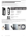
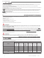
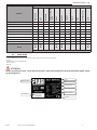
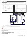
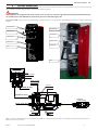
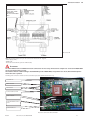
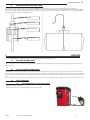
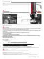
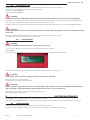
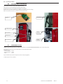
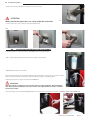
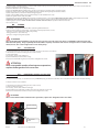
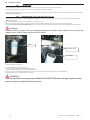
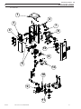
M0194A EN rev1 K44 MC INSTALLATION, USE AND MAINTENANCE MANUAL FM EN EN Translated from Italian DECLARATION OF CONFORMITY The undersigned: PIUSI S.p.A Via Pacinotti c.m. z.i.Rangavino 46029 Suzzara - Mantova - Italy HEREBY STATES under its own responsibility, that the equipment described below: Description : Diesel fuel dispenser Model : SELF SERVICE 100 FM SELF SERVICE 100 K44 SELF SERVICE 100 MC SELF SERVICE 70 FM SELF SERVICE 70 K44 SELF SERVICE 70 MC SELF SERVICE TANK 100 FM SELF SERVICE TANK 100 K44 SELF SERVICE TANK 100 MC SELF SERVICE TANK 70 FM SELF SERVICE TANK 70 K44 SELF SERVICE TANK 70 MC Serial number: refer to Lot Number shown on CE plate affixed to product Year of manufacture: refer to the year of production shown on the CE plate affixed to the product is in conformity with the legal provisions indicated in the directives : - Machine Directive 2006/42/EC - Low-Voltage Directive 2006/95/EC - Electromagnetic Compatibility Directive 2004/108/EC The documentation is at the disposal of the competent authority following motivated request at Piusi S.p.A. or following request sent to the email address: doc_tec@piusi.com The person authorised to compile the technical file and draw up the declaration is Otto Varini as legal representative. Suzzara, 29/12/2009 2 legal representative. Self Service 70/100 MC-FM-K44 M0194 Translated from Italian A A INDEX B GENERAL INFORMATION C GENERAL WARNINGS D SAFETY INSTRUCTION D1 FIRST AID RULES D2 GENERAL SAFETY RULES D3 TRANSPORT, HANDLING AND UNPACKING D4 DISPOSAL E USE AND AVAILABILITY OF MANUALS F IDENTIFICATION OF UNIT AND MANIFACTURER F1 MODELS F2 DATA PLATE G DESCRIPTION OF MAIN COMPONENTS G1 BODY G2 PUMPING UNIT G3 FUEL METER G3.1 MECHANICAL METERS G3.2 ELECTRONIC METERS G4 NOZZLE (for versions FM e MC G5 LEVEL INDICATOR (for versions FM e MC) G6 NOZZLE G7 DISPLAY COVER (for versions FM e MC) H TECHNICAL FEATURES H1 PROPER USE / FLUIDS PERMITTED H2 IMPROPER USE / FLUIDS NOT PERMITTED H3 POWER CONSUMPTION H4 HYDRAULIC PERFORMANCES H5 METERING ACCURACY I INSTALLATION I1 GENERAL INFORMATION I3 FIXING I4 HYDRAULIC CONNECTIONS I5 ELECTRIC CONNECTIONS I5.1 CONNECTION OF SINGLE-PHASE SELF SERVICE I6 PROBE OF LEVEL INDICATOR “OCIO” L STARTING L1 ELECTRIC CONNECTIONS L2 INITIAL STARTING CONDITIONS L3 INITIAL PRIMING L3.1 FIRST PRIMING ON SELF SERVICE K44 VERSION L3.2 FIRST PRIMING ON SELF SERVICE FM AND MC VERSION L3.2.1 CUT-OUT SYSTEM OF THE ELECTRONIC CONTROL SYSTEM FOR FIRST PRIMING ON SELF SERVICE FM AND MC VERSION L3.2.2 INITIAL PRIMING L3.2.3 STATION CONFIGURATION L4 FUEL METER CALIBRATION L4.1 K44 FUEL METER CALIBRATION L4.2 FUEL METER CALIBRATION SELF SERVICE FM/MC M DAILY USE M1 SELF SERVICE K44 M2 SELF SERVICE FM e MC M2.1 FUEL DISPENSING N ROUTINE MAINTENANCE N1 PUMP AND PIPES N2 DELIVERY HOSE AND NOZZLE N3 MANAGEMENT SYSTEM N4 OPERATIONS PRECEDING FILTER DISASSEMBLY N5 FILTERS N5.1 SUCTION FILTER N5.2 PUMP FILTER (available on models with PANTHER 72 only) N5.3 PULSER FILTER N5.4 DELIVERY FILTER (only for high Self Service versions) N5.5 FITTING INSTRUCTIONS FOR EXTERNAL FILTER ( Tank versions only) N6 TROUBLESHOOTING O SPECIAL MAINTENANCE P EXPLODED VIEWS M0194 INDEX 3 4 4 4 4 4 5 6 6 6 6 7 8 8 8 8 8 8 8 8 8 8 9 9 9 9 9 9 9 9 10 10 11 14 15 15 15 15 15 15 16 16 17 17 17 17 18 18 18 19 19 19 19 20 20 22 23 23 23 24 24 25 26 26 27 Self Service 70/100 MC-FM-K44 EN 3 EN Translated from Italian B GENERAL INFORMATION SELFSERVICE distributors have been developed for private distribution of Diesel fuel. All models show common features, such as a solid metal structure and self-priming pumps, but they differ in fuel meter type (mechanical or electronic); besides, some models are equipped with Electronic Delivery Control System. Additional options (anti-water filter, integrated level indicator, printer/ticket distributor) make this model range even wider. Reliability of pumping units, accurate measurement of product delivered and high performances of Control Systems are the strong point of SELFSERVICE. C GENERAL WARNINGS Warnings To ensure operator safety and to protect the dispensing system from potential damage, workers must be fully acquainted with this instruction manual before attempting to operate the dispensing system. Symbols used in the manual The following symbols will be used throughout the manual to highlight safety information and precautions of particular importance: WARNING This symbol indicates safe working practices for operators and/or potentially exposed persons. WARNING This symbol indicates that there is risk of damage to the equipment and/or its components. NOTE This symbol indicates useful information. Manual preservation This manual should be complete and legible throughout. It should remain available to end users and specialist installation and maintenance technicians for consultation at any time. Reproduction rights All reproduction rights are reserved by Piusi S.p.A. The text cannot be reprinted without the written permission of Piusi S.p.A. © Piusi S.p.A. THIS MANUAL IS THE PROPERTY OF PIUSI inc. ANY REPRODUCTION, EVEN PARTIAL, IS FORBIDDEN. D SAFETY INSTRUCTION All SELFSERVICE models have been developed and built according to the applicable EC rules concerning fundamental safety and health requirements. A copy of the manufacturer’s DECLARATION OF COMPLIANCE is supplied at the beginning of this manual. D1 FIRST AID RULES Contact with the product In the event of problems developing following EYE/SKIN CONTACT, INHALATION or INGESTION of the treated product, please refer to the SAFETY DATA SHEET of the fluid handled. Ingestion of toxic liquids by people Electrocution should fuel be ingested, do not induce vomiting, but let the person involved drink large quantities of milk or water disconnect the unit from the mains, or use a dry insulator as protection while moving the electrocuted person far from any conductor. Do not touch the electrocuted person with bare hands until he/she is far from any conductor. Ask qualified and trained people for help immediately Please refer to the safety data sheet for the product NOTE SMOKING PROHIBITED When operating the dispensing system and in particular during IN ALL CASES ASK FOR A DOCTOR IMMEDIATELY. D2 GENERAL SAFETY RULES Essential protective Wear protective equipment that is: equipment • suited to the operations that need to be performed; characteristics • resistant to cleaning products Personal protective equipment that must be wor Wear the following personal protective equipment during handling and installation: safety shoes; close-fitting clothing; protective gloves; safety goggles; instruction manual Never touch the electrical parts with wet hands. DANGER Do not switch the dispensing system on if the network connection cable or important parts of the apparatus are damaged, such as the inlet/outlet pipe, nozzle or safety devices. Replace the damaged pipe immediately. 4 Self Service 70/100 MC-FM-K44 M0194 Translated from Italian D3 EN TRANSPORT, HANDLING AND UNPACKING SELF SERVICE is supplied in non-stackable cardboard packing. Store and handle the unit paying attention to the indications supplied graphically on the packing. In case of lifting make sure that capacity of lifting means and accessories (bands, for example) are suitable. Handling and lifting equipment shall be used by authorized and properly trained personnel only. During standstill periods the unit , either in packed or unpacked conditions, shall be kept in a place sheltered from dust and weather (rain, humidity, sun, etc..). Remove the cardboard packing using scissors or a cutter. Operate carefully, to avoid damaging the unit. DIMENSIONS SELF SERVICE A SELF SERVICE 1391 290 365 990 280 359 A PACKING DIMENSIONS height = 1478 mm length = 488 mm depth = 400 mm B C SELF SERVICE TANK TOTAL WEIGHT: SELF SERVICE 100 FM SELF SERVICE 100 K44 SELF SERVICE 100 MC SELF SERVICE 70 FM SELF SERVICE 70 K44 SELF SERVICE 70 MC C B SELF SERVICE TANK 100 FM SELF SERVICE TANK 100 K44 SELF SERVICE TANK 100 MC SELF SERVICE TANK 70 FM SELF SERVICE TANK 70 K44 SELF SERVICE TANK 70 MC PACKING WEIGHT: Kg 5,5 PACKING DIMENSIONS OF SELF SERVICE TANK height = 1080 mm length = 480 mm depth = 400 mm Have the packing opened completely, two people must move the SELFSERVICE unit to a vertical position to facilitate reaching its final site. Once unpacked, the unit should always be kept in a vertical position. Put all packing elements (cardboard, wood, cellophane,polystyrene etc.) into the corresponding containers. Do not leave them in the environment or within children’s reach as they are potentially dangerous. They should be disposed of according to the regulations in force in the country where the unit will be used. Check the conditions of the unit making sure that no part shows such damages as compromise safety and functionality. In case of doubt, do not install the machine and contact the manufacturer’s Technical Service. Make sure that all accessories are available (see enclosure). After unpacking, assemble the unit as follows: - Fit the hose support (PICTURE 1 AND 2) - Tighten the screws and fix the hook in the desired position (picture 2) - Before mounting nozzle and hose, apply a sealant paste on the threads as indicated in picture 3. PICTURE 1 M0194 PICTURE 2 PICTURE 3 Self Service 70/100 MC-FM-K44 5 EN Translated from Italian D4 DISPOSAL The components must be given to companies that specialise in the disposal and recycling of industrial waste and, in particular: the DISPOSAL OF PACKAGING: the packaging consists of biodegradable cardboard which can be delivered to companies for normal recycling of cellulose. DISPOSAL OF METAL COMPONENTS The metal components, both painted and stainless steel, are usually recycled by companies that are specialised in the metal-scrapping industry. DISPOSAL OF ELECTRIC AND ELECTRONIC COMPONENTS: these have to be disposed by companies that are specialised in the disposal of electronic components, in accordance with the instructions of 2002/96/EC (see text of Directive below). ENVIRONMENTAL INFORMATION FOR CUSTOMERS IN THE EUROPEAN UNION European Directive 2002/96/EC requires that the equipement bearing this symbol on the product and/or its packaging must not be disposed of with unsorted municipal waste. The symbol indicates that this product should be disposed of separately from regular household waste streams. It is your responsibility to dispose of this and other electric and electronic equipment via designated collection facilities appointed by the government or local authorities. DISPOSAL OF OTHER PARTS: The disposal of other parts such as pipes, rubber seals, plastic components and cables should be entrusted to companies that special in the disposal of industrial waste. E USE AND AVAILABILITY OF MANUALS This manual describes the main features of all SELF SERVICE models and gives instructions concerning: - electrical and mechanical installations, - initial starting operations, - daily use. This manual does NOT cover subjects such as - calibration of fuel meters - configuration and operation of management system, - configuration and operation of level indicator. which are dealt with in a specific manual, supplied with each model station. ATTENTION Manual numbers and corresponding components (pump, fuel meter, etc.) are indicated for each model station in paragraph E1 (Table). All manuals are contained in an envelope supplied with a detailed list of same. This collection of manuals is an integral part of the product and shall be handed to the use and maintenance personnel according to EEC directive 98/37, in order to meet the training and information requirements set forth in EEC directive 98/37. Read the instructions carefully: they contain important information on safety during installation, use and maintenance. The manufacturer is not responsible for damages to people, things or to the unit when it is not used as indicated. Keep this manual in a safe place protected from humidity, heat, dust, oil, grease, etc: it will be needed for future reference and consultation. Do not remove, tear or modify any part of this manual for any reason. Should it be lost or damaged, ask the manufacturer for another copy, indicating manual number.This manual shall always follow the unit; should the unit be sold, the manual will be handed to the new user. ATTENTION The manufacturer reserves the right to modify any features of the SELF SERVICE unit at any time. F F1 IDENTIFICATION OF UNIT AND MANIFACTURER MODELS The table below shows the main components of each model of SELF SERVICE (shown in the following tables). The voltages and frequencies of all stations that are indicated in the table are 230 Volt and 50 Hz X X SELF SERVICE TANK 100 K44 M0042 M0194 X X X * X * X PA80 X PA120 K 44 X X X X X M0033 SELF SERVICE 100 K44 SELF SERVICE TANK 70 K44 E120 X WATER SEPARATOR FILTER SELF SERVICE 70 K44 M0064 MODELS PANTHER 72 COMPONENTS MANUALS (*) can be fitted externally 6 Self Service 70/100 MC-FM-K44 M0194 Translated from Italian EN X X X X X X X X FM BOX X X X X X X X X X X X X X X X X X X X X X X X M0147 X OCIO X BY-PASS FILTER X PA80 X PA120 X MC BOX X X X X X X X M0073 X M0042 M0194 X M0087 X SELF SERVICE TANK 100 MC 230V/50Hz SELF SERVICE TANK 70 MC 230V/50Hz X X SELF SERVICE TANK 100 FM 230V/50Hz SELF SERVICE TANK 70 MC 230V/50Hz X X SELF SERVICE 100 MC 230V/50Hz SELF SERVICE TANK 70 FM 230V/50Hz K600/3 X WATER SEPARATOR FILTER SELF SERVICE 100 FM 230V/50Hz SELF SERVICE 70 MC 230V/50Hz E120 X IMPRESORA SELF SERVICE 70 FM 230V/50Hz M0064 MODELS PANTHER 72 COMPONENTS MANUALS F2 DATA PLATE The SELF SERVICE stations feature an identification plate that is attached to the shell showing - Model - Serial number / Year of manufacture - Technical data - EC mark ATTENTION Before installing the unit, check that the model is right and suitable for currently available supply voltage and frequency. MANUFACTURER MODEL CODE TECHNICAL DATA TEAR OF MANIFACTURE PRODUCT MANUAL LOT NUMBER EC MARK M0194 Self Service 70/100 MC-FM-K44 7 EN Translated from Italian G G1 DESCRIPTION OF MAIN COMPONENTS BODY The SELF SERVICE body - all versions - consists of a strong treated-steel shell, closed on top by a plastic cap and a sturdy base for attaching it to the ground. - The front panel is entirely hinged to provide easy access to the internal components of the station (pump, filter, meter) and closed by a lock . Moreover, depending on the version, it may house the control panel The right side panel can be easily detached to allow installation or maintenance operations. ROOF NOZZLE SEAT HOSE HOOK LOCK AND KEY CONTROL PANEL DETACHABLE PANEL FRONT PANEL G2 PUMPING UNIT G3 FUEL METER Self-priming motor-driven vane pump, equipped with by-pass valve which allows the pump to continue operating for short periods of time when the delivery nozzle is closed. Single-phase self-ventilated induction motor, enclosed type (1P 55, as per EN 60034-5-86 laws), directly flanged on the pump. An ANGULAR MESH FILTER is connected to the pump intake for easy cleaning. For useful information on the units available on the Self Service stations, please refer to relevant handbooks specified on the summary table of paragraph E1. G3.1 MECHANICAL METERS G3.2 ELECTRONIC METERS G4 NOZZLE (for versions FM e MC) G5 LEVEL INDICATOR (for versions FM e MC) G6 NOZZLE G7 DISPLAY COVER (for versions FM e MC) Nutating-disk fuel meter with mechanical readout device, with wheels, indicating subtotals (which can be set to zero) and total (which can not be set to zero). Strong and reliable, the fuel meter can be set on site to achieve maximum precision levels. Further information is supplied by the manual indicated in table 2 - paragraph E1. The meter features a measurement system with high-precision oval gears designed for accurate fuel metering. It includes a strong drawn aluminium structure, a suction filter, and offers both easy maintenance and high reliability. Further information is supplied by the manual indicated in paragraph E1 (Table). SELF SERVICE is supplied with automatic nozzle, with delivery shutoff device operating when the tank is full. The efficient electronic indicator “OCIO” is integrated in the management system to check and measure fuel level in tanks. Further information can be found in the corresponding manual, specified in paragraph E1 (Table), supplied with the FM SELF SERVICE units. SELF SERVICE is supplied with automatic nozzle, with delivery shutoff device operating when the tank is full. In order to guarantee a suitable protection and a proper display visibility to Self Service units, even in extremely lit conditions, a special extractable protection has been fitted under the top which can be lowered in case of need. We recommend to keep it always down when the sunlight is very strong and when the Self Service door has to be opened 8 Self Service 70/100 MC-FM-K44 M0194 Translated from Italian H H1 EN TECHNICAL FEATURES PROPER USE / FLUIDS PERMITTED Transfer of Diesel fuel, viscosity from 2 to 5,35 cSt at 37,8 °C, flash point PM ≥ 55 °C. H2 IMPROPER USE / FLUIDS NOT PERMITTED Transfer of fluids having features different from those indicated above. In particular transfer of the following liquids: - petrol, solvents and inflammable liquids with PM < 55 °C (explosion/fire danger), - alimentary liquids (contamination of the same), - water (pump oxidation), - corrosive chemicals (pump corrosion), - liquids with viscosity >20 cSt (motor overload). H3 POWER CONSUMPTION SELF SERVICE stations shall be supplied with electric power having the same RATED VOLTAGE / FREQUENCY as shown on the DATA PLATE. The following max. variations can be accepted: - VOLTAGE +/- 5% - FREQUENCY +/- 2% The DATA PLATE also shows the MAX. POWER CONSUMPTION (in Ampere) to be taken into consideration when installing the electric safety devices required by the regulations in force and not supplied with the unit. Max. power consumption refers to operation corresponding to the proper use of the unit – i.e. DIESEL FUEL TRANSFER – and to power consumption parameters falling within the above-indicated limits. H4 HYDRAULIC PERFORMANCES Provided that installation, power consumption and use are correct and proper (proper use = TRANSFER OF FUEL OIL), SELF SERVICE stations supply the following performances: - Modelli SELF SERVICE 100 K44 F: PORTATA MAX 85 litri/minuto - Modelli SELF SERVICE 70 K44 F: PORTATA MAX 68 litri/minuto - Modelli SELF SERVICE 100 K44 TANK : PORTATA MAX 90 litri/minuto - Modelli SELF SERVICE 70 K44 TANK: PORTATA MAX 70 litri/minuto - Modelli SELF SERVICE 70 FM/MC: PORTATA MAX 68 litri/minuto - Modelli SELF SERVICE 100 FM/MC: PORTATA MAX 85 litri/minuto - Modelli SELF SERVICE tank 70 FM/MC: PORTATA MAX 70 litri/minuto - Modelli SELF SERVICE tank 100 FM/MC: PORTATA MAX 90 litri/minuto Pumps allow CONTINUOUS operation of the stations. H5 METERING ACCURACY After correct calibration on site, the fuel meter K44 ensures the following performances: ACCURACY: +/- 1% (after calibration, for flow rates over 10 l / min.). Thanks to the PULSER K600 METER and to the FM/MC control system which ensures precise CALIBRATION, the SELF SERVICE stations provide the following performance: ACCURACY: +/- 0.5% (after calibration, for flow rates above 5 litres/minute). For further details, see the handbook indicated on the summary table of paragraph E1 I I1 INSTALLATION GENERAL INFORMATION Even if SELF SERVICE stations are suitable for outdoor installation, longer life of the same and increased comfort for the operator during refuelling can be obtained by placing the units under a protective roof. Installation should be carried out by specialized personnel, following the instructions supplied in this chapter. ATTENTION Motors are not explosion-proof. DO NOT install SELF SERVICE in places with danger of explosion. SELF SERVICE stations can be connected both to underground and above-ground tanks. I2 POSITIONING GENERAL INFORMATION SELF SERVICE should be so positioned as to ensure - an easy removal of detachable panels when access to internal components is required; - compliance with max. distances and difference in height between station and tank; - correct and safe fixing of the body to the ground on a horizontal plane. Unit position results in the following parameters, characterizing each installation: Hp: priming height Ls: total length of suction piping – from foot valve to station (in meters) Correct operation of the units requires full respect of the following limits: Hp max: not exceeding 3 meters LS max: not exceeding 15 meters M0194 Self Service 70/100 MC-FM-K44 9 EN Translated from Italian I3 FIXING The station should be attached to the ground with screw anchors suitable for M12 screws, to be placed as indicated in the following pictures. Before fixing the unit, make sure that the bearing area for station frame is flat and strong. To facilitate SUCTION line connection, SELF SERVICE units are equipped both with rear and bottom inlets. Above-ground tank Underground tank 35 200 I4 13 59.5 140 13 37 138 24 118 48 48 95 70.6 95.6 70.5 59 78 155 60 R Diagram: fixing the unit to the ground. HYDRAULIC CONNECTIONS SUCTION LINE The diameter of the suction line in the Self Service and Self Service Tank stations should not be lower than 1” 1/2 Gas. The connector is 1” 1/2 female Gas. ATTENTION Always follow the below-listed instructions: - Use pipes and joints suitable for operation in vacuum conditions. - Use pipes and accessories suitable for Diesel fuel. Unsuitable materials can result in serious damage to the pump or to people; they can also cause pollution. - Do not use conical threaded connectors that could cause damage to the threaded connector on the pump filter if tightened excessively - Use wide-radius bends so that pressure losses are reduced to minimum levels. - Check that suction pipe is perfectly clean and free from scales. - Install a FOOT VALVE equipped with FILTER at suction pipe end. Place the foot valve on tank bottom. Foot valve and pipe must have the SAME DIAMETER. - Before starting installation, make sure that no packing material has been left in the pipes. 10 Self Service 70/100 MC-FM-K44 M0194 Translated from Italian I5 EN ELECTRIC CONNECTIONS Electric connections shall be carried out by specialized personnel in a professional way. Full compliance with the regulations in force in the country where the unit is installed and with the wiring diagrams contained in this manual is required. ATTENTION: SELF SERVICE is not equipped with safety switches. As a consequence, a power supply panel fitted with ground fault interrupter (suitable for the SELF SERVICE model involved) must be installed at supply side. For Self Service K44 : The electric panel can be reached by opening the front panel. It is pre-wired for SELF SERVICE components, according to the following diagram. FUEL METER K44 FUEL METER K44 JUNCTION BOX JUNCTION BOX NOZZLE SWITCH NOZZLE SWITCH PUMP FILTER WATER FILTER PUMP PUMP BLUE GREEN/YELLOW BROWN GREEN/YELLOW BLUE BROWN FUSE 10 A POWER IN 230V FUSE 10mA POWER IN 230V PG11 NOZZLE CONTACT NC Power 230V OUT PG11 BROWN BLUE GREEN/YELLOW PG9 BLUE/BLACK BLUE BROWN NOTE 1: should a tank level alarm be connected, replace the jumper on J1 with the alarm contact. This contact must be of “normally closed” type, that is it will be open in case of level alarm. M0194 Self Service 70/100 MC-FM-K44 11 EN Translated from Italian For Self Service FM e MC : SELF SERVICE is provided with JUNCTION BOXES containing terminals for connection of: - electric supply line, - data line RS 485 for PC connection (optional), - level indicator contact (FM versions). FM-BOX MC-BOX ELECTRICAL BOX NOZZLE SWITCH PULSER K600/3 NOZZLE SWITCH WATER SEPARATOR FILTER PULSER K600/3 PUMP FILTER WATER SEPARATOR FILTER PUMP FILTER PUMP PUMP The junction boxes, which can be reached by opening the front panel, are pre-wired to SELF SERVICE components according to the model involved and on the basis of the wiring diagram supplied here below. JP1 Self Service MC 12 Self Service 70/100 MC-FM-K44 M0194 Translated from Italian EN VERSIONE MCFP: INPUT LEVEL ALARM VERSIONE FM: OUT PUT ALARM OCIO NR.2 JP1 Self Service FM NOTE: The customer will just carry out the connections indicated in the diagram: - Power supply (230V) - RS485 to PC - Connection to Ocio Alarm (optional on MC models) ATTENTION For SELF SERVICE units no additional electric connections are necessary. All electronic components enclosed in FM/MC BOX are pre-wired and factory-tested. The installer and the station manager should NEVER open the FM/MC BOX, except when fuses in I/O, Ocio and Ocio printer cards have to be replaced. Following main connections shall be carried out and fuses replaced by qualified technicians only. RS485 DATA LINE POWER + GROUND FUSE MOTOR 8A FUSE 230 POWER 100 mA RIT POWER + GROUND FUSE POWER PRINTER CARD 100 mA RIT FUSIBLE TARJETA OCIO M0194 Electrónica Self Service FM con FM Box Self Service 70/100 MC-FM-K44 13 EN Translated from Italian RS485 DATA LINE POWER + GROUND FUSE MOTOR 8A FUSE 230 POWER 100 mA RIT POWER + GROUND FUSE POWER PRINTER CARD 100 mA RIT Electrónica Self Service MC con FM Box FUSE MOTOR 8A POWER + GROUND FUSE MOTOR 8A FUSE 230 POWER100 mA RIT I5.1 Electrónica Self Service MC con MC Box CONNECTION OF SINGLE-PHASE SELF SERVICE Connect the 230V-50/60Hz supply line to the box terminals JP1 in the junction boxes of FM and MCFP SELF SERVICE units. For MC version: in junction box “1” in MC box. No polarity requirements shall be met for Phase and Neutral wires. Connect the ground wire to an earth plate perfectly complying with the standards in force. 14 Self Service 70/100 MC-FM-K44 M0194 Translated from Italian I6 EN PROBE OF LEVEL INDICATOR “OCIO” FM Self Service units are equipped with a special level indicator (OCIO) in their standard version; this accessory is available as an optional for MC units. Probe of level indicator “Ocio” can follow the same path to the tank as station suction pipe. If possible, introduce OCIO probe into a tank coupling different from the one used for the intake pipe. Make sure that the probe is correctly placed on tank bottom (for further details, please refer to the handbook OCIO M0073 supplied with the Self Service FM-MC stations) CABLE CABLE CLAMP COUPLING PLUG TANK COUPLING L STARTING To have SELF SERVICE correctly started, carry out the following operations in the indicated order. L1 ELECTRIC CONNECTIONS After connecting the unit as described in paragraph H5, SELF SERVICE can be energized by means of the general switch placed by the installer on the line, before the unit. L2 INITIAL STARTING CONDITIONS SELF SERVICE is equipped with self-priming pump, which makes initial starting easier: in fact the suction pipe does not need to be filled completely with Diesel fuel. However quick priming can only be achieved if the pump is wet, that is if a minimum quantity of Diesel fuel is available inside the rotor chamber (this is particularly true when the difference in height between station and tank is remarkable). The pump is supplied with this minimum quantity, ready for use. If the installer believes the pump to be completely dry for any reason (long storage, for example), he shall wet the pump following a procedure at his choice. L3 INITIAL PRIMING L3.1 FIRST PRIMING ON SELF SERVICE K44 VERSION To prime the pump act as follows: • Extract the nozzle from its seat.The pump does not start automatically. M0194 Self Service 70/100 MC-FM-K44 15 EN Translated from Italian • Start the pump manually by moving the switch to ON (the switch can be operated only after extracting the nozzle). The pump starts immediately and keeps operating until the switch is moved to OFF (manually or by putting the nozzle back in its seat. ATTENTION: Should the pump not start, check that the switch on pump junction box is ON ON/OFF SWITCH SWITCH POSITION Operate the nozzle lever keeping the spout in a suitable container or in the suction container. At first air will come out of the nozzle; then, after a certain time, Diesel oil will start flowing out. ATTENTION Initial priming shall be carried out by qualified personnel, who will be present at all operations involved. If air comes out for over 2 minutes, STOP THE PUMP and make sure that: • pump is not operating in dry conditions, but that a minimum quantity of Diesel fuel is available (“wet conditions”); • suction pipe does not let any air in and that it is completely submersed; • filters are unclogged; • suction and/or delivery lines are unclogged; • installation has been carried out respecting the limits set forth in paragraph H2 (difference in height, pipe diameter and length). • The release valve is closed. Continue dispensing fuel until a steady air-free flow is obtained. Release the nozzle lever. Put the nozzle back in its seat. The pump stops. L3.2 FIRST PRIMING ON SELF SERVICE FM AND MC VERSION L3.2.1 CUT-OUT SYSTEM OF THE ELECTRONIC CONTROL SYSTEM FOR FIRST PRIMING ON SELF SERVICE FM AND MC VERSION All SELF SERVICE functions are managed by a management system. This system, however, can be overridden during start up or maintenance operations requiring repeated pump starting. In these cases simplified starting procedures (no request for pin code and no record of delivery data) may be useful. To this purpose both FM and MC boxes are supplied with an AUTO/MAN system, to change from AUTOMATIC mode (request for pin code to access the delivery function) to MANUAL mode (no request for pin code). ATTENTION In manual mode the FM/MC management system does not record any delivery data. Before operating the AUTO/MAN switch, put the general switch in OFF position. In MANUAL mode: - LCD’s can be off or continue showing the information displayed on changing mode (from AUTO to MAN); - no PIN CODE is required to activate the pump; it will start as soon as the nozzle is extracted from its seat and stop when the nozzle is put back; - no indication of fuel quantity delivered by SELF SERVICE can be obtained. 16 Self Service 70/100 MC-FM-K44 M0194 Translated from Italian EN By the side: the override system of the electronic management system in FM Box, triggered by operating the AUTO/MAN switch. Below: the override system of the electronic management system in MC Box, triggered by moving a small jumper. WITHOUT JUMPER L3.2.2 JUMPER IN AUTO POSITION INITIAL PRIMING To prime the pump act as follows: • Extract the nozzle from its seat. • The pump will start immediately and will continue operating until the nozzle is put back in its seat. Operate the nozzle lever keeping the spout in a suitable container or in the suction container. At first air will come out of the nozzle; then, after a certain time, Diesel oil will start flowing out. ATTENTION Initial priming shall be carried out by qualified personnel, who will be present at all operations involved. If air comes out for over 2 minutes, STOP THE PUMP and make sure that: •pump is not operating in dry conditions, but that a minimum quantity of Diesel fuel is available (“wet conditions”); • suction pipe does not let any air in and that it is completely submersed; • filters are unclogged; • suction and/or delivery lines are unclogged; • installation has been carried out respecting the limits set forth in paragraph H4 (difference in height, pipe diameter and length). • The release valve is closed. Continue dispensing fuel until a steady air-free flow is obtained. Release the nozzle lever. Put the nozzle back in its seat. The pump stops. Move AUTO/MAN switch to AUTO. The management system changes to “normal operation” mode (see Management System Software manual). L3.2.3 STATION CONFIGURATION Each SELF SERVICE station can be adjusted to the Manager’s specific requirements by CONFIGURING the management system. ATTENTION Configuration of the management system is extremely important and should be carried out by specialised personnel. Read the specific manual carefully and thoroughly before carrying out any configuration activities. After configuration, USER PINS shall be assigned to SELF SERVICE users so that they can use the pump as described in the System Management manual. L4 FUEL METER CALIBRATION L4.1 K44 FUEL METER CALIBRATION Before using SELF SERVICE station, METERING ACCURACY should be checked. Act as follows: • Extract the nozzle and start the pump as described in the preceding paragraph. • Use a graduated container. M0194 Self Service 70/100 MC-FM-K44 17 EN Translated from Italian ATTENTION: To carry out a correct accuracy test follow the below-listed instructions: • Use a graduated precision container with a minimum capacity of 20 liters. • Before starting the test, make sure that no air is left in the system: let fuel flow out until a full regular flow is obtained. • Dispense fuel uninterruptedly at max. flow rate. • Stop dispensing by closing the nozzle quickly. • Fill the container up to the graduated area. Do not dispense at low flow rate for long times, but at max. flow rate for short periods of time. • Wait for possible foam to disappear, then compare the indication on the container with the value shown by SELF SERVICE. Should accuracy NOT be satisfactory, CALIBRATE the FUEL METER following the instructions supplied in manual M0033. ATTENTION: Differences up to 0,2 liters in 20-liter deliveries fall within the accuracy ensured (+/- 1%). L4.2 FUEL METER CALIBRATION SELF SERVICE FM/MC Before using SELF SERVICE station, METERING ACCURACY should be checked. Act as follows: • Enter an enabled USER PIN. • Use a graduated container. ATTENTION To carry out a correct accuracy test follow the below-listed instructions: • Use a graduated precision container with a minimum capacity of 20 litres. • Before starting the test, make sure that no air is left in the system: let fuel flow out until a full regular flow is obtained. • Dispense fuel uninterruptedly at max. flow rate. • Stop dispensing by closing the nozzle quickly. • Fill the container up to the graduated area. Do not dispense at low flow rate for long times, but at max. flow rate for short periods of time. • Wait for possible foam to disappear, then compare the indication on the container with the value shown by SELF SERVICE. Should accuracy NOT be satisfactory, CALIBRATE the FUEL METER following the instructions supplied in the specific manual. ATTENTION Differences up to 1/10th of a litre on deliveries amounting to 20 litres fall within the ensured accuracy limits (+/- 0.5%). M M1 DAILY USE SELF SERVICE K44 ATTENTION Fuel must be supplied EXCLUSIVELY in the user’s presence and under his strict supervision. 1 Uncoil the hose on the hook and extract the nozzle from its seat. 2 Check that readout is set to zero or set it to zero by turning the corresponding knob. 3 Start the pump manually by moving the switch to ON (the switch can only be operated after extracting the nozzle). The pump will start immediately. ATTENTION Never operate the nozzle lever before introducing the nozzle into the container to be filled. 4 Start delivery by operating the nozzle lever. SELF SERVICE shows the quantity supplied. ATTENTION: Delivery can be interrupted when desired. When delivery is interrupted by releasing the nozzle lever, the pump goes on operating and the fuel circulates inside the pump thanks to the by-pass valve. This operating condition shall not exceed some minutes. Should delivery be interrupted for longer times, stop the pump by operating the switch on the nozzle holder. 5 After delivery release the nozzle lever, coil the hose on the hook and put the nozzle back in its seat.When the nozzle reaches its seat, the switch in the nozzle-holder is moved to OFF and the pump stops. 18 Self Service 70/100 MC-FM-K44 M0194 Translated from Italian M2 EN SELF SERVICE FM e MC FM/MC management system ensures that access to all SELF SERVICE models is limited to enabled users exclusively. Enabled users can be identified by the management system in two ways: - by entering a 4-figure PIN CODE, or - by introducing an ELECTRONIC KEY. ATTENTION All USERS provided with a PIN CODE should be suitably trained and at least informed on the contents of this paragraph. Configuration of the management system can also include the request for optional data to be entered by the user (vehicle registration number, odometer value, quantity to be supplied). Further details can be found in the management system manual. Should these options not be selected, the management system will enable the pump and fuel dispensing as soon as an enabled PIN CODE is identified. ATTENTION The pump does not start as soon as enabled. Pump starting is controlled by a switch placed in nozzle seat and operated by the nozzle itself. After being enabled the pump starts after being extracted from its seat; it will stop when it is put back correctly. No additional manual operation is required to start or stop the pump. M2.1 FUEL DISPENSING ATTENTION Fuel shall be ABSOLUTELY dispensed under the User’s strict supervision. In case of simple configuration (no optional data to be entered), dispensing takes place as follows: 1 Enter PIN CODE If the management system identifies an enabled pin code, the following messages are displayed and the pump is enabled. 2 Uncoil the hose from the hook and take the nozzle out of its seat.The management system starts the pump. ATTENTION Never operate nozzle lever before putting the nozzle in the container to be filled. 3 Operate nozzle lever to start dispensing fuel. The management system displays quantity supplied. ATTENTION Dispensing can be stopped when desired. In case of prolonged break (break time can be set by the Manager at Configuration stage), the pump is stopped and disabled. Repeat operations from point 1. to resume dispensing. 4 After dispensing, coil the hose on the hook and put the nozzle back in its seat. The management system stops the pump. N ROUTINE MAINTENANCE SELF SERVICE has been so designed and built as to require minimum maintenance. However the following ORDINARY inspections and maintenance operations shall be carried out regularly to ensure safety and efficiency of the station, N1 PUMP AND PIPES Inspect pump, pipes and the other internal components (filter and pulser). Keep them clean. Check that no leakage is available on flanged or threaded connections and that flexible hoses do not show any damage. M0194 Self Service 70/100 MC-FM-K44 19 EN Translated from Italian N2 DELIVERY HOSE AND NOZZLE Keep delivery hose and nozzle clean. Make sure that: 1 Hose does not show any damage caused by vehicle transit. 2 Threaded connections are tightened and without any leakage. 3 Banjo unions (at station outlet and on nozzle) turn smoothly and show no leakage. 4 Hole of automatic stop sensor at nozzle hose end (spout) is clean. HOSE SUPPORT AUTOMATIC STOP PROBE HOLE AUTOMATIC NOZZLE FLANGED CONNECTION BANJO UNIONS DELIVERY HOSE FLANGED CONNECTION BANJO UNIONS 90° N3 MANAGEMENT SYSTEM FM/MC management system does not require any maintenance except REPLACING PRINTER PAPER (only on models with printer) . The printer, integrated in the system with FM box, operates with thermal paper. Roll dimensions: - external diameter: 50 mm - internal diameter: 13 mm - width: 57 mm Paper should be replaced when the printer shows a red stripe lengthwise. To replace paper roll act as follows: 20 Self Service 70/100 MC-FM-K44 M0194 Translated from Italian EN 1 Open SELF SERVICE front panel to reach FM BOX back and extract the movable protective shield as indicated by the arrow. 1 2 Unscrew the knobs and open the printer door. 3 Open the door. 2 3 4 Lift the paper dragger acting on the lever indicated by the arrow, until position “4a” is reached. 4 4/a 5 6 5 Using your left hand, seize the paper roll support pin and unscrew the knob to the right. 6 Remove the paper roll, place a new one, introduce the support pin and screw the knob on it. 7/a 7/b 8 7. Introduce the paper into the printing head having aligned it correctly. Close the retaining lever and act on the knurled wheel to let some paper go out of the cutter (on FM BOX front). 8. Introduce the paper into the guide. 9. Close the printer door and turn the knobs. M0194 Self Service 70/100 MC-FM-K44 21 EN Translated from Italian 10. Close Self Service door. Check that the paper has come out correctly. ATTENTION Make sure that the paper does not roll up under the cutter door. 10 11. Lift the cutter door, exert a certain pressure and pull off the ticket. 11/a N4 OPERATIONS PRECEDING FILTER DISASSEMBLY To facilitate operations on filters (see below), SELF SERVICE stations are equipped with: • PAN to collect possibly spilled liquids, placed under the delivery cartridge filter. • RELEASE VALVE, installed on suction filter The procedures described in this paragraph should always be followed before carrying out any operations on filters. They are absolutely required to ensure safety when working and to prevent any polluting effects. 1) Close the valve placed on suction line before SELF SERVICE inlet. ATTENZIONE This valve, which is usually not present in tank under ground installations, MUST BE USED in tank above ground installations. The valve, which is not supplied with the station, should be fitted by the installer 2) Put the small pipe connected with the RELEASE VALVE in a vessel and open the valve with a screwdriver. BE CAREFUL: DIESEL FUEL LEAKING OUT! 22 Self Service 70/100 MC-FM-K44 M0194 Translated from Italian EN 3) Start the pump and deliver fuel into a container with suitable capacity. The nozzle will start supplying fuel, but thanks to the release valve the flow will decrease progressively and finally stop. 4) Put the nozzle back in its seat; the pump will stop. 5) Close the RELEASE VALVE carefully moving the pipe (connected to it) and move back to a higher position. 6) Move the general switch of the station to OFF to prevent accidental starting during maintenance of filters. 7) Clean /replace filters as described in the following paragraphs. 8) Clean collecting PAN carefully, so that possible leakages can be identified more easily. 9) Move the general switch of the unit to ON. 10) Keeping the unit front door OPEN, start the pump and deliver fuel into a vessel until a CONTINUOUS AIR-FREE FLOW is obtained. Close the nozzle WITHOUT PUTTING IT BACK IN ITS SEAT: the pump will operate in bypass mode, producing the maximum delivery pressure. 11) During bypass operation CHECK THE ABSENCE OF LEAKAGES ARE AVAILABLE, then put the nozzle back in its seat. 12) Lock station door. N5 FILTERS SELF SERVICE is equipped with different filters performing different functions. Inspection and cleaning (or replacement) of each filter is extremely important to ensure: - protection of station components (K44, pump, nozzle); - lasting performance (max. flow rate); - protection of engines using fuel supplied. ATTENZIONE Dirty or partially obstructed filters can increase pressure losses in such a way as to cause a remarkable reduction of the max. flow rate of the pump . Dirty or partially obstructed filters in pump suction line can cause a strong increase in suction vacuum which, in turn, can result in higher noise levels of the pump. N5.1 SUCTION FILTER It is placed just before the suction mouth of the pump. To inspect and clean it act as follows: 1 remove filter cover after unscrewing the two screws on same; 2 extract basket filter; 3 if necessary, clean it: wash and blow it; 4 put the basket filter back in the filter casing; 5 inspect and clean the O-ring. Put cover in position and tighten the screws. ATTENTION: After a reasonable number of maintenance operations, replace the flat gasket of the cover filter. N5.2 PANTHER 72 only) PUMP FILTER (available on models with It is installed in pump body, as a standard accessory of PANTHER pump, just after the suction filter. As a consequence it will not require frequent cleaning. To inspect and clean it act as follows: 1 remove filter cover after unscrewing the two screws on same; 2 extract net filter using pliers; 3 if necessary, clean it: wash and blow it through; 4 put the filter back in pump body making sure it does not stand out of cover seat; 5 inspect and clean the flat seal. Put cover in position and tighten the screws. ATTENTION: After a reasonable number of maintenance operations, replace the flat gasket of the cover filter. FILTER COVER FILTER COVER SCREW M0194 PUMP FILTER Self Service 70/100 MC-FM-K44 23 EN Translated from Italian N5.3 PULSER FILTER The pulser filter is an additional protection which prevents foreign bodies from entering the oval gear pulser. As it is installed after the suction filters, it does not require any regular checking and cleaning. However, should the filter be cleaned for any reasons and/or in case of special maintenance operations, remove the pulser (if necessary) and proceed as described in PULSER MANUAL. N5.4 DELIVERY FILTER (only for high Self Service versions) The delivery filter is provided with a WATER-ABSORBING CARTRIDGE. It represents a fundamental element for the protection of the engines using fuel delivered by the station. This kind of filter separates and absorbs possible water available in fuel oil. When water is absorbed, the filtering capacity is progressively reduced with a resulting increase in pressure loss (caused by the filter). The filter CAN NOT BE CLEANED OR REGENERATED; after a certain operating time it must be replaced to restore station performances (max. flow rate). ATTENTION: Filter life is usually very long but it can vary remarkably depending on the quantity of water available in fuel. In case of a large quantity of water, the filter could get obstructed in a few minutes. FILTER END PLATE FILTER MALE BORDER To replace the filter act as follows: 1 loosen head filter by means of chain tongs; 2 unscrew and remove the filter from the head manually; 3 inspect and, if necessary, clean head thread and filter seal seat; 4 place a new filter (complete with seal) manually in position and screw as tightly as possible (wet the seal with Diesel fuel); 5 tighten the filter (not too much) using the chain tongs ATTENTION Some station models are equipped with DOUBLE-CARTRIDGE FILTER. Both cartridges operate simultaneously and must be replaced at the same time. 24 Self Service 70/100 MC-FM-K44 M0194 Translated from Italian N5.5 FITTING INSTRUCTIONS FOR EXTERNAL FILTER ( Tank versions only) Self Service Tank versions are fitted only with an external filter. A few operations are necessary for fitting: they are hereafter illustrated, both for the mechanical version (K44) and electronic versions (MC, FM). SELF SERVICE TANK K44 SELF SERVICE TANK MC - FM 1 1 2 2 3 3 4 4 5 5 Kit with screws, nuts, seal for filter fitting is supplied with each Self Service Station. M0194 6 Self Service 70/100 MC-FM-K44 25 EN EN Translated from Italian N6 TROUBLESHOOTING PROBLEM MOTOR NOT TURNING MOTOR WIN’T START WITH NOZZLE CLOSED LOW OR NO FLOW METER NOT ACCURATE ENOUGH THE NOZZLE SHUT OFF TOO OFTEN POSSIBLE CAUSES POSSIBLE SOLUTIONS No electric power Turn the pump ON/OFF switch to the ON position. Recock the external residual current circuit breaker. Check the electrical connections. Fuses burned out Replace the fuses in the electric panel Nozzle Lever control micro switch brocken. Replace the microswitch Problems with the motor If the rotor is jammed, dismount and check for damage and obstructions then ermount. Contact the service Department Electric Voltage too low Check the voltage is not more than 5% below the nominal voltage. Excessive suction pressure Lower the Self Service with rispect to the tank or increase the diameter of the tubing. High loss of head Use shorting tubing or odf greater diameter Suction tube resting on the bottom of the tank Raise the suction tube Lowlevel in the suction tank Fill the tank Air entering the suction tube or in the pump Check the seals connection in the tubing and the leevl of diesel fuel in the tank Low rotation speed Check the voltage at the motor Regulate the voltage of the motor and/or use the larger diameter cables. Check valve blocked Clean or replace Tank filter clogged Clean the filter Pump filter clogged Clean the filter Cim-tek filter plogged Replace the filter Fluid Leaking Check the connection seals and the condition of the rubber tubes Meter chamberv obstructed Clean the Meter chamber Air in the suction line Clean the meter measuring chamber Insufficient calibration Calibrate the meter (see M0033) Probe hole automatic stop is obstructed Clean probe hole of automatic stop spout O SPECIAL MAINTENANCE All maintenance operations not described in this manual should be regarded as SPECIAL MAINTENANCE. As such they must by carried out by our specialized SERVICE technicians exclusively. AUTHORIZED DEALER: 26 Self Service 70/100 MC-FM-K44 M0194 Translated from Italian P SELF SERVICE K44 - SELF SERVICE TANK K44 SELF SERVICE K44 EXPLODED VIEWS LR_A00035 SELF SERVICE TANK K44 PULSER 1 2 3 7 4 8 12 6 5 14 10 9 11 M0194 EN Self Service 70/100 MC-FM-K44 27 EN Translated from Italian SELF SERVICE MC-FM - SELF SERVICE TANK MC-FM SELF SERVICE MC - FM LR_A00036 13 1 2 14 3 4 6 7 5 8 15 12 9 10 11 28 Self Service 70/100 MC-FM-K44 M0194 Translated from Italian Q MANIFACTURER’S DATA - SERVICE MANUFACTURER: PIUSI S.p.A. DOCUMENT TYPE: General description and installation, starting, use and maintenance instructions ISSUE: Bulletin M0194A Rev. 1 PRODUCT: Fuel distributor with fuel meter, for private use MODEL: All models belonging to SELF SERVICE range, single or three phase, with different voltages/frequencies, fitted with mechanical/electronic fuel meter. COMPLIANCE: EC Mark (see Declaration of Conformity, page 33) SERVICE: supplied by Service Centers of Authorized Dealers The data contained in this manual was supplied by the Manufacturer, who reserves the right to modify them at any time without notice. M0194 EN Self Service 70/100 MC-FM-K44 29 Bulletin M0194AEN REV1


![121290 CR-4000 Controller User Manual [English].pub](http://vs1.manualzilla.com/store/data/005770288_1-ff1b31ed544f6d88740c7f5db9da46b2-150x150.png)