1
MOD
E
R460
L
Limited lifetime consumer warranty
Directed Electronics ("Directed") promises to the original purchaser to repair or replace
with a comparable reconditioned model any Directed unit (hereafter the "unit"), excluding without limitation the siren, the remote transmitters, the associated sensors and accessories, which proves to be defective in workmanship or material under reasonable use during the lifetime of the vehicle provided the following conditions are met: the unit was professionally installed and serviced by an authorized Directed dealer; the unit will be professionally reinstalled in the vehicle in which it was originally installed by an authorized
Directed dealer; and the unit is returned to Directed, shipping prepaid with a legible copy
of the bill of sale or other dated proof of purchase bearing the following information: consumer's name, telephone number and address; the authorized dealers name, telephone
number and address; complete product description, including accessories; the year, make
and model of the vehicle; vehicle license number and vehicle identification number. All
components other than the unit, including without limitation the siren, the remote transmitters and the associated sensors and accessories, carry a one-year warranty from the date
of purchase of the same. This warranty is non-transferable and is automatically void if: the
original purchaser has not completed the warranty card and mailed it within ten (10) days
of the date of purchase to the address listed on the card; the unit's date code or serial number is defaced, missing or altered; the unit has been modified or used in a manner contrary to its intended purpose; the unit has been damaged by accident, unreasonable use,
neglect, improper service, installation or other causes not arising out of defects in materials or construction. The warranty does not cover damage to the unit caused by installation or removal of the unit. Directed, in its sole discretion, will determine what constitutes excessive damage and may refuse the return of any unit with excessive damage. TO
THE MAXIMUM EXTENT ALLOWED BY LAW, ALL WARRANTIES, INCLUDING BUT NOT LIMITED TO EXPRESS WARRANTY, IMPLIED WARRANTY,
WARRANTY OF MERCHANTABILITY, FITNESS FOR PARTICULAR PURPOSE
AND WARRANTY OF NON-INFRINGEMENT OF INTELLECTUAL PROPERTY,
ARE EXPRESSLY EXCLUDED; AND DIRECTED NEITHER ASSUMES NOR
AUTHORIZES ANY PERSON OR ENTITY TO ASSUME FOR IT ANY DUTY,
OBLIGATION OR LIABILITY IN CONNECTION WITH ITS PRODUCTS.
DIRECTED DISCLAIMS AND HAS ABSOLUTELY NO LIABILITY FOR ANY
AND ALL ACTS OF THIRD PARTIES INCLUDING ITS AUTHORIZED DEALERS OR INSTALLERS. DIRECTED SECURITY SYSTEMS, INCLUDING THIS
UNIT, ARE DETERRENTS AGAINST POSSIBLE THEFT. DIRECTED IS NOT
OFFERING A GUARANTEE OR INSURANCE AGAINST VANDALISM, DAMAGE OR THEFT OF THE AUTOMOBILE, ITS PARTS OR CONTENTS; AND
HEREBY EXPRESSLY DISCLAIMS ANY LIABILITY WHATSOEVER, INCLUDING WITHOUT LIMITATION, LIABILITY FOR THEFT, DAMAGE AND/OR
VANDALISM. THIS WARRANTY DOES NOT COVER LABOR COSTS FOR
MAINTENANCE, REMOVAL OR REINSTALLATION OF THE UNIT OR ANY
© 2008 directed electronics
i
CONSEQUENTIAL DAMAGES OF ANY KIND. IN THE EVENT OF A CLAIM
OR A DISPUTE INVOLVING DIRECTED OR ITS SUBSIDIARY, THE PROPER
VENUE SHALL BE SAN DIEGO COUNTY IN THE STATE OF CALIFORNIA.
CALIFORNIA STATE LAWS AND APPLICABLE FEDERAL LAWS SHALL APPLY
AND GOVERN THE DISPUTE. THE MAXIMUM RECOVERY UNDER ANY
CLAIM AGAINST DIRECTED SHALL BE STRICTLY LIMITED TO THE
AUTHORIZED DIRECTED DEALER'S PURCHASE PRICE OF THE UNIT.
DIRECTED SHALL NOT BE RESPONSIBLE FOR ANY DAMAGES WHATSOEVER, INCLUDING BUT NOT LIMITED TO, ANY CONSEQUENTIAL DAMAGES,
INCIDENTAL DAMAGES, DAMAGES FOR THE LOSS OF TIME, LOSS OF
EARNINGS, COMMERCIAL LOSS, LOSS OF ECONOMIC OPPORTUNITY
AND THE LIKE. NOTWITHSTANDING THE ABOVE, THE MANUFACTURER
DOES OFFER A LIMITED WARRANTY TO REPLACE OR REPAIR THE CONTROL MODULE AS DESCRIBED ABOVE. Some states do not allow limitations on
how long an implied warranty will last or the exclusion or limitation of incidental or consequential damages. This warranty gives you specific legal rights and you may also have
other rights that vary from State to State.
This product may be covered by a Guaranteed Protection Plan ("GPP"). See your authorized Directed dealer for details of the plan or call Directed Customer Service at 1-800876-0800. Directed security systems, including this unit, are deterrents against possible
theft. Directed is not offering a guarantee or insurance against vandalism, damage or theft
of the automobile, its parts or contents; and hereby expressly disclaims any liability whatsoever, including without limitation, liability for theft, damage and/or vandalism.
Directed does not and has not authorized any person or entity to create for it any other
obligation, promise, duty or obligation in connection with this security system.
Make sure you have all of the following information from your dealer:
A clear copy of the sales receipt, showing the following:
➤
➤
➤
➤
➤
➤
➤
➤
➤
ii
Date of purchase
Your full name and address
Authorized dealer's company name and address
Type of alarm installed
Year, make, model and color of the automobile
Automobile license number
Vehicle identification number
All security options installed on automobile
Installation receipts
© 2008 directed electronics
Table of contents
Limited lifetime consumer warranty . . . . . . . . . . . . . . . . . . . . . . . . . . . . . . . . . . . . . . . i
2-way LCD remote control . . . . . . . . . . . . . . . . . . . . . . . . . . . . . . . . . . . . . . . . . . . . . 1
LCD screen . . . . . . . . . . . . . . . . . . . . . . . . . . . . . . . . . . . . . . . . . . . . . . . . . . . . . . . . . 2
Standard remote configuration . . . . . . . . . . . . . . . . . . . . . . . . . . . . . . . . . . . . . . . . . . 3
What is included . . . . . . . . . . . . . . . . . . . . . . . . . . . . . . . . . . . . . . . . . . . . . . . . . . . . . 4
Importtant information. . . . . . . . . . . . . . . . . . . . . . . . . . . . . . . . . . . . . . . . . . . . . . . . . 4
System maintenance . . . . . . . . . . . . . . . . . . . . . . . . . . . . . . . . . . . . . . . . . . . . . . 5
FCC/ID notice . . . . . . . . . . . . . . . . . . . . . . . . . . . . . . . . . . . . . . . . . . . . . . . . . . 6
Replacement remote controls . . . . . . . . . . . . . . . . . . . . . . . . . . . . . . . . . . . . . . . . . . . . 7
2-way LCD remote control functions . . . . . . . . . . . . . . . . . . . . . . . . . . . . . . . . . . . . . 7
Standard configurations (1-way and 2-way remote controls). . . . . . . . . . . . . . . . 7
Standard LCD icon configurations (2-way only). . . . . . . . . . . . . . . . . . . . . . . . . 9
Remote operation . . . . . . . . . . . . . . . . . . . . . . . . . . . . . . . . . . . . . . . . . . . . . . . . . . . 12
System signal paging features . . . . . . . . . . . . . . . . . . . . . . . . . . . . . . . . . . . . . . 12
Out of range notification . . . . . . . . . . . . . . . . . . . . . . . . . . . . . . . . . . . . . . . . . 13
Programming LCD remote . . . . . . . . . . . . . . . . . . . . . . . . . . . . . . . . . . . . . . . . . . . . 14
To enter programming mode . . . . . . . . . . . . . . . . . . . . . . . . . . . . . . . . . . . . . . 14
Beeps/Vibration On/Off . . . . . . . . . . . . . . . . . . . . . . . . . . . . . . . . . . . . . . . . . . 14
Illumination On/Off. . . . . . . . . . . . . . . . . . . . . . . . . . . . . . . . . . . . . . . . . . . . . 15
Page notification . . . . . . . . . . . . . . . . . . . . . . . . . . . . . . . . . . . . . . . . . . . . . . . . 15
To exit programming mode. . . . . . . . . . . . . . . . . . . . . . . . . . . . . . . . . . . . . . . . 15
Using your systtem . . . . . . . . . . . . . . . . . . . . . . . . . . . . . . . . . . . . . . . . . . . . . . . . . . . 16
Active arming . . . . . . . . . . . . . . . . . . . . . . . . . . . . . . . . . . . . . . . . . . . . . . . . . . 16
Passive arming . . . . . . . . . . . . . . . . . . . . . . . . . . . . . . . . . . . . . . . . . . . . . . . . . . 17
Multi-level security arming . . . . . . . . . . . . . . . . . . . . . . . . . . . . . . . . . . . . . . . . 18
Disarming . . . . . . . . . . . . . . . . . . . . . . . . . . . . . . . . . . . . . . . . . . . . . . . . . . . . . 19
Disarming without a transmitter. . . . . . . . . . . . . . . . . . . . . . . . . . . . . . . . . . . . 21
Dome light control (optional). . . . . . . . . . . . . . . . . . . . . . . . . . . . . . . . . . . . . . 22
Silent mode. . . . . . . . . . . . . . . . . . . . . . . . . . . . . . . . . . . . . . . . . . . . . . . . . . . . 22
Panic mode . . . . . . . . . . . . . . . . . . . . . . . . . . . . . . . . . . . . . . . . . . . . . . . . . . . . 23
Valet mode . . . . . . . . . . . . . . . . . . . . . . . . . . . . . . . . . . . . . . . . . . . . . . . . . . . . 24
Nuisance prevention® circuitry . . . . . . . . . . . . . . . . . . . . . . . . . . . . . . . . . . . . 25
Auxiliary outputs (options) . . . . . . . . . . . . . . . . . . . . . . . . . . . . . . . . . . . . . . . . . . . . 26
Diagnostics . . . . . . . . . . . . . . . . . . . . . . . . . . . . . . . . . . . . . . . . . . . . . . . . . . . . . . . . 27
Arming diagnostics . . . . . . . . . . . . . . . . . . . . . . . . . . . . . . . . . . . . . . . . . . . . . . 27
Disarming diagnostics . . . . . . . . . . . . . . . . . . . . . . . . . . . . . . . . . . . . . . . . . . . . 28
Table of zones . . . . . . . . . . . . . . . . . . . . . . . . . . . . . . . . . . . . . . . . . . . . . . . . . . 29
Interpreting zone diagnostics. . . . . . . . . . . . . . . . . . . . . . . . . . . . . . . . . . . . . . . 30
© 2008 directed electronics
iii
Owner recognition. . . . . . . . . . . . . . . . . . . . . . . . . . . . . . . . . . . . . . . . . . . . . . . . . . . 31
Rapid resume logic . . . . . . . . . . . . . . . . . . . . . . . . . . . . . . . . . . . . . . . . . . . . . . . . . . 32
Power saver mode . . . . . . . . . . . . . . . . . . . . . . . . . . . . . . . . . . . . . . . . . . . . . . . . . . . 32
Programming . . . . . . . . . . . . . . . . . . . . . . . . . . . . . . . . . . . . . . . . . . . . . . . . . . . . . . . 33
Installation
n options . . . . . . . . . . . . . . . . . . . . . . . . . . . . . . . . . . . . . . . . . . . . . . . . . . 37
Vehicle recovery system (VRS®) . . . . . . . . . . . . . . . . . . . . . . . . . . . . . . . . . . . . . . . . 37
Arming the VRS . . . . . . . . . . . . . . . . . . . . . . . . . . . . . . . . . . . . . . . . . . . . . . . . 38
Triggered sequence, VRS . . . . . . . . . . . . . . . . . . . . . . . . . . . . . . . . . . . . . . . . . . 39
Disarming the VRS. . . . . . . . . . . . . . . . . . . . . . . . . . . . . . . . . . . . . . . . . . . . . . 40
Security & convenience expansions . . . . . . . . . . . . . . . . . . . . . . . . . . . . . . . . . . . . . . 41
Glossary of terms . . . . . . . . . . . . . . . . . . . . . . . . . . . . . . . . . . . . . . . . . . . . . . . . . . . . 43
Quick reference guide . . . . . . . . . . . . . . . . . . . . . . . . . . . . . . . . . . . . . . . . . . . . . . . . 45
iv
© 2008 directed electronics
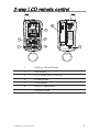
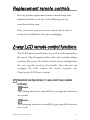
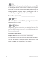
2-way LCD remote control
6
3
1
5
1.
Auxiliary Channel Button
2.
Arm Button
3.
LCD Screen (see LCD Screen)
4.
Disarm Button
5.
Panic Button
6.
Battery Compartment
7.
Program Button
© 2008 directed electronics
1-800-274-0200
RPN 7341V/P/X
2(66) CODES
4
FCC ID:EZSDEI489
2
7
1
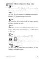
LCD screen
1
2
3
4
5
6
7
17
16
15
14
8
13
9
12
10
11
1. Transmit
10. Battery level indicator
2. Out of range
11. Remote sending
3. Receive
12. Vibrate mode
4. Aux Output 2 or 3
13. Ignition
5. Garage door (519H2 option)
14. Vehicle number
6. Warn Away®
15. Door
7. Alarm
16. Arm
8. Trunk or Hood
17. Disarm
9.
2
Sensor
© 2008 directed electronics
Standard remote configuration
controls the Lock–Arm/Panic On/Panic Off function.
controls the Unlock–Disarm/Panic Off function.
controls Silent Mode™ and an Auxiliary Output (2).
or
controls the Panicc On/Off function (hold for 2-
seconds).
and
P
pressed together control an Auxiliary Output (3).
(located on back of the remote) selects the vehicle to control
and also provides user selection of LCD remote response .
© 2008 directed electronics
3
What is included
➤
Control module
➤
1 four-button 2-way LCD transmitter
1 four-button transmitter
➤
note: On both remotes the panic button is the same color.
➤
➤
➤
➤
➤
➤
➤
Wire harnesses
The 514N six-tone programmable siren
In-vehicle status LED indicator light
A push-button Valet switch
Your warranty registration
Failsafe® Starter Kill ready circuitry
(may require additional labor)
548T receiver/antenna
Important information
Congratulations on the purchase of your state-of-the-art vehicle
security system. This system has been designed to provide years
of trouble-free operation. Due to the complexity of this system,
it must be installed by an authorized dealer only. Installation of
this product by anyone other than an authorized dealer voids the
warranty. All dealers are provided with preprinted dealer certificates to verify that they are authorized.
This owner’s guide should help you to get the most out of your
system. Please take the time to read it prior to using the system.
4
© 2008 directed electronics
➜ System maintenance
This system needs no specific maintenance beyond remote
control battery replacement. The 2-way remote is powered by a
1.5V AAA battery. The 1-way remote is powered by a pair of 3V,
CR2016 batteries.
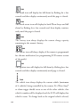
Battery Level Indicator (2-way remote)
The Battery Level indicator has four level indicators that serve as
a visual indication of battery charge. When the battery reaches a
low charge level that requires replacement, the remote control
will generate a single notification chirp, and the Battery Level
indicator will flash continuously.
FULL
REPLACE
EMPTY
Battery Replacement (2-way remote)
Gently pull the end of the battery door away from the top of the
remote control then slide the door up to expose the battery and
remove the expired battery. Place the new battery into the remote
control observing the correct polarity. When power is returned
the remote control will display all icons in the LCD and generate
all beeper tones once. Press any button on the remote to terminate the beeper tone review.
➜ your warranty
Your warranty registration must be returned and the bar code
serial number must not be removed. If the warranty registration
is not returned, you do not have a warranty. It is also necessary to
© 2008 directed electronics
5
keep your proof of purchase, which reflects that the product was
installed by an authorized dealer. Make sure that you receive the
warranty registration from your dealer.
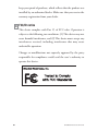
➜ FCC/ID notice
This device complies with Part 15 of FCC rules. Operation is
subject to the following two conditions: (1) This device may not
cause harmful interference, and (2) This device must accept any
interference received, including interference that may cause
undesirable operation.
Changes or modifications not expressly approved by the party
responsible for compliance could void the user's authority to
operate this device.
6
© 2008 directed electronics
Replacement remote controls
You can purchase replacement remote controls from your
Authorized Dealer or on-line at the following web site:
www.directedstore.com
Once you receive your new remote control, please refer to
instructions included on the remote packaging.
2-way LCD remote control functions
The LCD remote control buttons are used to send commands to
the system. The descriptions below reflect the standard configuration for this system. The buttons can be custom configured for
the user’s specific needs by the installer. Also, the user can
configure the LCD remote for certain responses (see
Programming LCD Remote section).
➜ Standard configurations (1-way and 2-way remote
controls)
Button
The arming function is controlled by pressing this button for
one second.
Button
The disarming function is controlled by pressing this button for
one second.
© 2008 directed electronics
7
Button
Silent Mode™ and an optional auxiliary function are controlled
by pressing this button. (Silent Mode™ works by pressing this
button for less than one second before arming or disarming. An
optional auxiliary function, such as trunk release, can be
controlled by pressing this button for 1.5 seconds.)
The auxiliary output controls __________________________.
or
Button
The panic feature is controlled by pressing this button for
approximately two seconds.
and
Buttons
An optional auxiliary convenience or expansion function that
you have added to your system can be activated by pressing these
buttons simultaneously.
The auxiliary output controls_________________________.
Program Button (on
rear of 2-way LCD remote only)
Use this button to select the vehicle to control from the remote.
Also use this button to configure response characteristics from
the LCD remote (see Programming 2-Way Remote).
8
© 2008 directed electronics
➜ Standard LCD icon configurations (2-way only)
Icon
The transmit icon will be displayed while the remote control is
transmitting a command to the vehicle.
Icon
The signal icon will be displayed if a command is transmitted to
the vehicle but the command page is not received.
Icon
The receive icon will be displayed while the remote control is
receiving a page from the vehicle.
Icon
The auxiliary and sensor icons will display which auxiliary is operating, or which security sensor (zone 2,4 or 7) is in Warn Away®
or alarm state.
Icon
The garage door icon—for use with optional 519H2.
and
Icons
The above Warn Away® displays when a security feature has been
tripped, but not to full alarm.
and
Icons
The above icons will display when a security feature has been
tripped to a full alarm condition.
© 2008 directed electronics
9
Icon
The trunk icon will display for full alarm by flashing for a few
seconds and then display continuously until the page is cleared.
Icon
The shock sensor icon will display for both Warn Away® and full
alarm by flashing for a few seconds and then display continuously until the page is cleared.
Icon
The battery icon always displays the current charge capacity
remaining in the remote’s battery.
Icon
The vibrate icon will always display if the remote is programmed
for vibrator notification (see programming LCD remote section
of the guide).
Icon
The ignition icon will display for full alarm by flashing for a few
seconds and then display continuously until page is cleared.
Icon
The vehicle icon always displays the current vehicle (maximum
of 4 vehicles) being controlled by the remote. If a Warn Away®
or alarm trigger should occur at one of the other vehicles, that
vehicle’s number will be displayed and the LCD will display that
vehicle’s status. To change back to the original vehicle selected,
10
© 2008 directed electronics
press and release the program button until the vehicle number is
shown.
For example, If the remote was originally on vehicle number 1 and
a trigger page was received for vehicle number 2, the remote will
show the trigger alarm and show number 2 on the display. After
clearing the page, press and release the program button until number
1 is displayed. Now you can operate the alarm system on vehicle
number 1.
Icon
The door icon will display for full alarm by flashing for a few
seconds and then display continuously until the page is cleared.
Icon
The arm icon will flash when the system is locking the doors and
display continuously until the system is armed.
Icon
The disarm icon will flash when the system is unlocking the
doors and display continuously until the system is disarmed.
© 2008 directed electronics
11
Transmitter functions
This system uses a computer-based learn routine to learn the
transmitter buttons. This makes it possible to assign any transmitter button to any system function. The transmitter initially
comes programmed with Standard Configuration, but may also
be customized by an authorized dealer. The buttons described in
this manual correspond to a Standard Configuration transmitter.
Remote operation
The system operates at 434 MHz and incorporates Directed’s proprietary out-board technology transceiver. The high frequency combined
with Binary Data communication achieves superior range with twoway communication.
➜ System signal paging features
A page is the signal the control module sends to the remote control
as confirmation of receipt of a command or alarm system status.
When the remote control receives a page it will generate a page
notification to the user (notifications are audible beeps and-or
vibration) and the LCD Icons will display the current system status.
Command Page
When a command (arm/disarm, or auxiliary channel) from the
remote control is sent and received, the system will send a
command page back to confirm receipt.
12
© 2008 directed electronics
Alarm Page
If the alarm system is triggered while armed, an Alarm Page will be
sent to the remote control. When the remote receives an Alarm
Page, the LCD icons will display the alarm system status information and the remote control will generate beeps and-or vibration.
An Alarm Page alert is a series of 5 groups of 4 rapid beeps
(shock, trunk, door, ignition, or hood trigger) and the LCD icon
that caused the alarm will display. The remote will beep and or
vibrate every 60 seconds to alert the user that the alarm system
was triggered and will continue until the alarm page is cleared.
Page Recognition (Acknowledgement)
To clear a page alert/notification, quickly press any button on
the remote control. This can be performed at any time during or
after the page notification has occurred.
The remote control will not send a command to the system at
this time; it will only clear future repeats of the page notification.
The next time a button is pressed on the remote control it will
send a command to the system.
➜ Out of range notification
If a command is issued from the remote, but the remote is set to
the incorrect vehicle or is beyond the range of the vehicle to
receive the command, the remote responds with 3 set of 2 quick
beeps and the
© 2008 directed electronics
icon will flash 3-times.
13
Programming LCD remote
➜ To enter programming mode
Press and hold the
P
button until one long beep is heard.
Programming mode to customize the remote’s response is now
entered.
note: If no buttons are pressed within 5-seconds, programming mode will exit with 2-beeps.
➜ Beeps/Vibration On/Off
Press
to select beeps/vibration On/Off. Beeps alone, vibra-
tion alone, beeps and vibration, or no beeps and vibration can be
selected. Refer to the table below for these settings.
Beep/Vibrate settings
Programming response Icon display*
Beeps only (default)
1-beep
Siren icon On
Vibrate only
1-vibrate
Vibrate icon On
Beep & Vibrate
1-beep and 1-vibrate
No Beep and No Vibrate 1 long beep
Vibrate and siren icon
On
Vibrate and siren
icons Off
*Note: This is icon display during programming.
14
© 2008 directed electronics
➜ Illumination On/Off
Press
to select LCD backlight illumination On/Off. The
LCD backlight will illuminate when a remote button is pressed,
or an alarm status page is received.
LCD Backlight settings Programming response
ON
1-beep, backlight ON
OFF
2-beeps, backlight OFF
➜ Page notification
The remote control can be programmed to notify the user of a
page (audibly beeping if the vehicle’s status changes, e.g. door
unlocked, engine started, vehicle violation, etc.). On the LCD
remote press
to select page On/Off. One beep is page On,
Two beeps is page Off. When programmed off the remote will not
give any notification that a page was received from the vehicle.
Note: If programmed Off, no alarms will be notified to the
remote. Command information (armed/disarmed) will be notified to the remote.
➜ To exit programming mode
The LCD remote control will exit programming mode after 5seconds of inactivity and will emit 2 long beep.
© 2008 directed electronics
15
Using your system
The buttons described in this manual correspond to the standard
configuration. Remember, this is not the only way your transmitter may be set up. It can be custom configured to meet your
needs. See your installer for additional details.
➜ Active arming
You can arm the system by pressing
of your remote for one
second. When the system arms, from the vehicle you will hear a
short siren sound, or chirp, and see the parking lights flash once.
If the power door locks are controlled by the system, the doors
will also lock. While the system is armed, the in-vehicle’s status
LED will flash approximately once per second, indicating that
the system is actively protecting your vehicle. If you hear a
second chirp after arming and note that the in-vehicle’s status
LED is flashing in groups, see the Diagnostics Section of this
guide. This extra chirp is called Bypass Notification.
The LCD remote responds to active arming with one beep and
the
icon will flash 5-times to indicate successful arming of
the system.
If the LCD remote beeps twice after arming, the system has detected
an active sensor that should be checked. For example, a door open
icon will be displayed flashing 5-times on the LCD screen.
16
© 2008 directed electronics
Passive arming
The system can be programmed to arm itself automatically (called
passive arming). If the system is programmed for passive arming, it
will automatically arm 30 seconds after the ignition is turned off
and the system detects that you have left the vehicle by opening and
closing a door. Whenever the system is in its 30-second passive
arming countdown, the in-vehicle status LED will flash twice as
fast as it does when the system is armed. At the 20-second point of
the countdown, the siren will chirp to indicate that the system is
about to arm. At the 30-second point, the parking lights will flash
to indicate that the system is armed.
The LCD remote responds to passive arming with one beep and
the
icon will flash 3times to indicate successful arming of
the system.
note: If any protected entry point (such as a door or a
switch-protected trunk or hood) is open, the system will
not passively arm (unless forced passive arming is programmed on. See Programming Options section.) Additionally, if a door, hood or trunk is triggered during the
arming countdown, the 30-second countdown starts over.
When armed your vehicle is protected as follows:
➤
➤
➤
Light impacts trigger the Warn Away® signal. When triggered,
the siren chirps and the parking lights flash for a few seconds.
Heavy impacts trip a Triggered Sequence. The sequence
consists of the siren sounding continuously and the parking
lights flashing for a pre-programmed period, which can
range in duration from 1 to 180 seconds.
If a door is opened, the system will immediately start
© 2008 directed electronics
17
➤
➤
➤
chirping the siren and flashing the parking lights. Three
seconds later, the siren output changes to a continuous blast.
This progressive response gives you time to disarm the system with your LCD remote if you inadvertently open the
door while the system is armed, while still providing instant
response (even if the door is immediately closed).
Turning on the ignition key will trip the same progressive response as opening a door.
The optional starter kill prevents the vehicle’s starter from
cranking.
Any full trigger of the alarm system will immediately send an
alarm page to your remote informing you that your vehicle
should be checked.
➜ Multi-level security arming
Multi-Level Security Arming allows you to select which of the
security system's inputs or sensors will be active and which will
be bypassed at the time that the system is armed. (See the Table
of Zones section of this guide.) Pressing
again within five
seconds of arming the security system will activate the MultiLevel Security Arming feature. Each time
is pressed again, a
different security level is selected. The different security levels
can be selected as follows:
➤
Press
once: The siren chirps once. The system is armed.
➤
Press
a second time within five seconds: The siren
chirps twice followed by a long chirp. Zone 2 is now
bypassed.
18
© 2008 directed electronics
➤
Press
a third time witihin 5 seconds, the siren chirps 3
times then followed by a long chirp. Zone 4 is now bypassed.
➤
Press
a fourth time within five seconds: The siren cirps
four times follwed by a long chirp. Zone 2 and 4 are now
bypassed.
➤
Press
a fifth time within five seconds: The siren chirps
five times followed by a long chirp. All input zones, except the
ignition are now bypassed.
➤
Hold down the
to begin the Multi-Level-Security Arming
cycle over again.
note: Multi-Level Security Arming only applies to a single arming cycle. Once the system is disarmed and then
re-armed, all the zones will be active again.
After each press of the
to reach the next level of security, the
remote will emit normal arm notification (1 beep and 5 flashes
of the
icon). For easiest operation in reaching each level of
security, press
immediately after each notification.
➜ Disarming
To disarm the system, press
. You will hear two chirps, and
the parking lights will flash twice. If the power locks are
connected to the system, the doors will unlock. If the siren chirps
either four or five times when disarming, refer to the Diagnostics
section of this guide. This is called Tamper Alert.
© 2008 directed electronics
19
The remote will indicate disarm notification with 2 beeps and 5
flashes of the
icon. If disarming after the system has been
triggered, the remote control will send a diagnostic notification
as a reminder. These diagnostic notifications are:
1. If a sensor triggered the system, the remote will emit 4 quick
beeps and the LCD screen will indicate which sensor (5flashes) tripped the alarm.
2. If a switch (Zone 1, 3, or 5) triggered the system, the remote
will emit 4 quick beeps and the LCD screen will indicate
which switch (5 flashes) tripped the alarm.
3. If the system was triggered so many times that NPC is active
the remote will emit the above notifications with 5 beeps
instead of 4.
20
© 2008 directed electronics
➜ Disarming without a transmitter
This feature allows you to disarm the security system without the
remote transmitter should it be lost, damaged, or disabled. In order
to disarm the system without a remote transmitter, you must have
the vehicle’s ignition key and know where the Valet button is
located. Be sure to check with the installer for the location and the
number of presses of the Valet button required to disarm the system.
To disarm the security system,
turn the ignition to the ON position. Press the Valet button the
preset number of times (one to
DRW-35
five times) within 15 seconds. After five seconds the system will
disarm. If the system does not disarm, you may have waited too long;
turn the ignition off and on and try again.
Location of Valet Button_________________________________
Number of Pulses______________________________________
important! The unit can be programmed to respond to
one to five pulses of the Valet button for the disarm function. Be sure to check with the installer for the desired
programming.
The LCD remote will indicate disarm notification with 4 quick
beeps and 5 flashes of the
© 2008 directed electronics
and triggered zone icons.
21
➜ Dome light control (optional)
security only
The dome light activates for 30 seconds after the system is
disarmed.
Ignition controlled
The dome light activates for 30 seconds after the ignition is
turned Off.
door controlled
The dome light activates for 30 seconds after the system sees a
door has closed. (If door was held open for longer than 3
minutes the dome light will not illuminate.)
full
The dome light activates for 30 seconds after seeing door closure,
ignition, or security disarm. (This is the factory setting.)
➜ Silent mode
To temporarily turn off the arm or disarm chirps, use Silent
Mode™. Press
for less than one second before arming or
disarming, and the confirmation chirp(s) will be eliminated for
that one operation only. If you want the arm/disarm chirps
turned off permanently, your dealer can do this for you.
note: The Warn Away® response to lighter impacts is
bypassed if the system is armed using Silent Mode. This
ensures that no chirps will be emitted by the siren in an
area you want chirp-free. The system is still fully capable
of triggering. Only the Warn Away® response is bypassed.
22
© 2008 directed electronics
The LCD remote responds with the normal arm/disarm notifications in silent mode. (If the remote has beeps programmed
On, the remote will beep.)
➜ Panic mode
note: On both remotes the panic button is the same color.
LCD remote
If you are threatened in or near your vehicle, you can attract
attention by triggering the system with your LCD remote. Just
press
or
button for approximately two seconds, and
you will enter Panic Mode. The siren will sound and the parking
lights will flash for the programmed siren duration. To stop
Panic Mode at any time, press
or
button on the LCD
remote again.
The LCD remote responds with one beep and display of the
icon upon entering Panic Mode.
4-button remote
If you are threatened in or near your vehicle, you can attract
attention by triggering the system with your transmitter. Just
press
or
for approximately two seconds, and you will
enter Panic Mode. The siren will sound and the parking lights
will flash for the programmed siren duration. To stop Panic Mode
at any time, press
© 2008 directed electronics
, or
on the remote transmitter again.
23
➜ Valet mode
You can prevent your security system from automatically arming
and triggering by using Valet Mode. This is very useful when
washing the vehicle or having it serviced. In Valet Mode, the
security system will not arm, even with the remote transmitter,
but all convenience functions (door locks, trunk release, etc.)
will continue to work normally.
To enter or exit Valet Mode:
1. Turn the ignition on.
2. Turn the ignition off.
3. Press and release the Valet
DRW-35
button within 10 seconds.
The status LED will light solidly if you are entering Valet Mode,
and it will go out if you are exiting Valet Mode.
The remote will respond with 5 flashes of the
icon and 2
beeps on entering or exiting Valet® Mode.
To enter or exit Valet Mode using the transmitter:
1. Open any vehicle door.
Quickly press the following buttons in the sequence indicated.
2. Press
.
3. Press
.
4. Press
again.
The in-vehicle status LED will light solidly if you are entering
Valet® Mode, and it will go out if you are exiting Valet® Mode.
24
© 2008 directed electronics
➜ Nuisance prevention® circuitry
Your system has Directed’s Nuisance Prevention® Circuitry
(NPC®). It prevents annoying repetitive trigger sequences due to
faulty door pin switches or environmental conditions such as
thunder, jackhammers, airport noise, etc.
Example
If the alarm triggers three times within a 60-minute period and
each time the same sensor or switch triggers the alarm, NPC® will
interpret those triggers as false alarms. After the third trigger,
NPC® ignores, or bypasses, that sensor or switch (along with any
other sensors or switches sharing the same zone) for 60 minutes.
If the bypassed sensor tries to trigger the system while it is being
bypassed, the 60-minute bypass period will start over. This ensures
that a sensor that continually triggers will remain bypassed.
Doors are covered by NPC® differently; if the alarm is triggered
by an open door for three full cycles, the doors will be bypassed
until the trigger ceases.
note: Arming and disarming the system does not reset this
function. In order to reset a bypassed zone, the same zone
must not trigger for 60 minutes, or ignition is turned on.
If testing your system, it is important to remember that the
NPC® programming can cause zones to be bypassed and
appear to stop working. If five chirps are heard when disarming, NPC® has been engaged. If you wish to clear the
NPC® memory, turn the ignition key on.
NPC® is On/Off programmable. See your dealer and the
Programming section of this guide for more information.
© 2008 directed electronics
25
Auxiliary outputs (options)
This system also supplies outputs that can control convenience
options such as remote control trunk release and window automation. Consult your dealer for available options for your system.
Channel 2 Trunk release: When connected, pressing
for 1.5
seconds will remotely release the vehicle trunk lid.
Channel 3 auxiliary output: When connected, pressing
and
will immediately activate this output to control an
additional convenience option.
The remote will respond with a page notification consisting of
one long beep and for 4 seconds displays the channel number on
the LCD screen. This occurs at the remote after the system has
received the command to activate any of the Auxiliary outputs.
26
© 2008 directed electronics
Diagnostics
The microprocessor at the heart of your security system is
constantly monitoring all of the switches and sensors that are
connected to it. It detects any faulty switches and sensors and
prevents them from disabling the entire system. The microprocessor will also record and report any triggers that occurred
during your absence. Refer to the System Status Chirps and Table
of Zones charts for diagnostic information.
➜ Arming diagnostics
If the system is armed while an input is active (door open, sensor
triggering, etc.) the unit will chirp once when arming and then
one more time a few seconds later. This is called Bypass
Notification.
note: Bypass Notification will not occur when using
Silent Mode™ or if chirps have been programmed OFF.
The security system will ignore the input that was active when
the system was armed, until the input goes away. Three seconds
later the system will monitor that input normally. For example,
if your vehicle has interior light exit delay, and you arm the
system before the interior light goes out, you may hear Bypass
Notification chirps. Once the light shuts off, however, the doors
are monitored normally.
© 2008 directed electronics
27
➜ Disarming diagnostics
Extra disarm chirps are the Tamper Alert. If four chirps are heard
when disarming, the system was triggered in your absence. If five
chirps are heard, a zone was triggered so many times that Nuisance
Prevention® Circuitry has bypassed that zone (see NPC section of
this guide). The in-vehicle status LED will indicate which zone was
involved. (See Table of Zones section of this guide.) The system will
retain this information in its memory, and continue to chirp four
or five times each time it is disarmed, until the next time the ignition key is turned on.
➜ System status chirps
The siren will chirp when arming/disarming the system. The
pattern of chirps will audibly report the system’s status as
described below.
Action
28
Number of Chirps
Description
Arm
1
System armed
Arm
1 (3-second delay), 1
System armed with
Bypass Notification
Disarm
2
System disarmed
Disarm
4
System disarmed with
Tamper Alert
Disarm
5
System disarmed NPC®
active
© 2008 directed electronics
➜ Table of zones
The zone number is the number of LED flashes used by the
system to identify that input. The standard input assignments
are listed below, along with spaces to write in any optional
sensors or switches you have had installed.
Zone - Number
of LED Flashes
Description
1
Instant trigger - often used
for trunk pinswitches
2
Shock sensor input - a light
impact activates warn away
and a heavier impact activates
full alarm.
3
Door switch trigger
4
Optional sensor inputs for
warn away and full
alarm notification.
5
Ignition trigger
© 2008 directed electronics
Dealer-Installed
Options
29
➜ Interpreting zone diagnostics
Warn Away responses are not reported by arming or disarming
diagnostics. If you receive a Bypass notification when arming or
a Tamper Alert notification when disarming, look at the invehicle status LED. Active or triggered zones will be indicated by
a pattern of blinks by this LED.
Example
If Zone 3 was active or triggered, the in-vehicle LED will blink
three times with a two-second pause. Then it will blink three
times again, and repeat until the ignition is turned on.
note: Your system stores the last six triggered zones in
memory. If your system has been triggered but the LED
has been reset by turning on the ignition, your dealer can
still recall the last six zones that were triggered. Contact
your dealer for details.
Code hopping
The receiver and transmitters each use mathematical formulas
called algorithms to change their codes each time the transmitter
is used. This technology has been developed to increase the security of the unit. The control unit knows what the next codes
should be. This helps to keep the transmitter "in sync" with the
control unit even if you use the remote control out of range of
the vehicle. However, if the transmitter has been pressed many
times out of range of the vehicle, or if the battery has been
removed, it may get out of sync with the control unit and fail to
operate the system. To re-sync the remote control press
30
of
© 2008 directed electronics
the transmitter several times within range of the vehicle. The
alarm will automatically re-sync and respond to the transmitters
normally.
Owner recognition
Owner Recognition is a feature available exclusively from Directed.
Using the Directed Bitwriter®, a hand-held programming tool,
your dealer can program many of the system settings. The
programmer makes it possible to program different settings for
each transmitter that is used with the system. Then, whenever a
specific transmitter is used, the system will recall the settings
assigned to that transmitter. Owner Recognition lets up to four
users of the system have different settings that meet their specific
needs. It is almost like having four separate alarms in your vehicle,
one for each user.
note: Owner Recognition cannot be programmed without a Directed Bitwriter® and the necessary software.
Check with your dealer for more information.
© 2008 directed electronics
31
Rapid resume logic
This Directed system will store its current state to non-volatile
memory. If power is lost and then reconnected, the system will
recall the stored state from memory. This means if the unit is in
Valet Mode and the battery is disconnected for any reason, such
as servicing the car, when the battery is reconnected the unit will
still be in Valet Mode. This applies to all states of the system
including arm, disarm, VRS®, and Valet Mode.
Power saver mode
Your system will automatically enter Power Saver Mode while
armed or in Valet® Mode, after a period of time in which no
operation has been performed. This lowers the current draw to
the vehicle’s battery. Power Saver Mode takes over under the
following conditions:
➤
Power Saver when the system is armed: After the system has
been armed for 24 hours, the in-vehicle LED will flash at
half its normal rate, decreasing the system's current draw.
➤
Power Saver in Valet® Mode: When the system enters Valet®
Mode the in-vehicle LED illuminates steadily. If the vehicle
is not used (ignition is not turned on) for a period of one
hour while the system is in Valet® Mode, the LED will shut
off. If the system remains in Valet® Mode, the LED will
come back on the next time the ignition is turned on and
then back off.
32
© 2008 directed electronics
Programming
Programming options control what your system does during
normal operation, and require few or no additional parts.
However, some may require additional installation labor.
The following is a list of the program settings, with the factory
settings in Bold:
➤
➤
➤
➤
Active arming (only with the remote) or passive arming (automatic arming 30-seconds after the last door has been
closed).
Arming/disarming confirmation siren chirps on or off.
The ignition controlled door lock feature on or off: With
this feature on, the doors will lock three seconds after the
ignition is turned on, and the doors are closed, and unlock
when the ignition is turned off. The system will not lock the
doors when the ignition is turned on with any door open.
The bitwriter is not needed to program theses separately, it
should be in the programming grid to do these 2 independently. Ignition lock and unlock are independent features
and can be programmed separately.
Passive door locking (with passive arming) or active door
locking (only when arming with the remote). Passive locking
allows the vehicle's doors to lock when the security system
passively arms (after the 30 second countdown). This feature
only works if passive arming has been programmed.
© 2008 directed electronics
33
note: When programmed for passive arming and active
lock, if the system is disarmed without a door being
opened, the system will relock the doors when it passively rearms.
➤
Panic mode enabled/disabled with the ignition on: Some
states have laws against siren capability in a moving vehicle.
➤
Forced passive arming on or off: If your system is
programmed for passive arming and the forced passive
arming feature has been programmed on, the system will
passively arm after one hour, even if a protected entry has
been left open. This feature is useful if a door has been left
ajar when leaving the vehicle. Forced passive arming ensures
that the security system will be armed in every situation.
note: When the system passively arms after one hour, the
entry point that has been left open, and anything connected to the same zone, is bypassed and cannot trigger
the system. However, the remaining inputs to the system
are fully operational.
➤
Automatic Engine Disable (AED) on or off: The purpose of
this feature is to protect the vehicle from being stolen at all
times, regardless of whether or not the alarm is armed. If
AED is programmed on, the starter of the vehicle will be disabled 30 seconds after the ignition is turned off. Once the
key is turned off, the in-vehicle LED will flash slowly (onehalf its normal armed rate) to indicate the AED arming
cycle. Thirty seconds later, the starter of the vehicle will be
disabled. To start the car, it will be necessary to disarm the
system with the remote. It is also possible to disarm the AED
34
© 2008 directed electronics
feature by turning the ignition key to the RUN position and
pressing the Valet® button the programmed number of
times. AED is disabled when the system is in Valet® Mode.
note: This feature will only function if the Failsafe®
Starter Kill relay has been installed.
➤
Full trigger response 30 or 60 seconds: This determines how
long the full triggered sequence lasts. Some states have laws
regulating how long a security system can sound before it is
considered a nuisance. If your installer is programming the
security system with the Directed Bitwriter, the full triggered
response can be programmed for any duration ranging from
1 to 180 seconds.
➤
Nuisance Prevention® Circuitry on or off: Please refer to the
NPC® section of this manual for a complete explanation of
how NPC® operates. If NPC® is programmed off, the security system will respond to inputs from any sensor indefinitely.
note: Because many states have laws regulating security
systems, programming NPC® off may cause your system
to violate state laws.
➤
Comfort Closure Off: Windows will close upon locking the
vehicle.
➤
Forced Passive Arming Off: If passive arming is on and a door
is left open the system will be armed after 30-seconds.
➤
Panic with Ignition Off: Prevents the Panic button on the remotes
from activating panic with ignition On (not allowed in some
states).
© 2008 directed electronics
35
➤
Progressive door trigger on or off: When the system is armed
and a door is opened, the system responds with ten chirps
prior to beginning the full triggered sequence. If an instant
trigger is desired, the progressive door trigger can be programmed off.
➤
Valet® pulse count: The number of presses of the Valet®
button required to disarm the security system, AED, or the
VRS® system can be programmed from one to five presses. The
default setting is one press.
➤
Siren tones and chirp volume: The output of the Revenger®
Soft Chirp® siren consists of six different tones in sequence.
Any of these tones can be eliminated by your dealer, resulting in a unique, easily identifiable siren sound. The siren
chirps can be either full volume or six decibels quieter than
the full alarm blast.
36
© 2008 directed electronics
Installation options
The system has many options that may require extra parts and
labor. Some of the possibilities are listed here.
➤
Progressive unlocking: In most cars with electric power door
locks, the system can be configured so that when the system is
disarmed, only the driver’s door unlocks. A second press of the
button unlocks the other doors.
➤
Vehicle Recovery System (VRS®): VRS is an anti-carjacking
device designed to help in the safe recovery of your vehicle
in case of a carjacking. Please refer to the Vehicle Recovery
System section of this guide for a complete explanation of
how the Vehicle Recovery System operates.
®
Vehicle recovery system (VRS )
The optional VRS feature is designed to ensure that any unauthorized user of your vehicle (even if using your keys and remote control)
will not be able to permanently separate you from your vehicle.
The VRS cannot prevent a carjacking attempt; however, it does
ensure that if your vehicle is taken by an unauthorized user, it will
be disabled (after several progressive warnings) as safely as
possible. Should a carjacking occur, the VRS allows you to
concern yourself with your personal safety without worrying
about your property.
© 2008 directed electronics
37
Directed has engineered this vehicle security system, the Failsafe®
Starter Kill, and the VRS feature to provide the best combination of personal safety and property protection available. When
properly installed, the system can never inadvertently stop your
vehicle in traffic or on railroad tracks while the vehicle is in operation. It is unlike other systems that shut down your engine
while it is running. This system is designed to perform starter interrupt, or starter kill. The Failsafe® Starter Kill cannot shut
down an already-running engine – it can only prevent an engine
from starting in the first place.
important! Any installation that allows this product to
shut down a vehicle's engine when it is running is contrary to the product’s design and intended usage, and
Directed hereby expressly disclaims any liability resulting
therefrom.
➜ Arming the VRS
To arm the VRS, turn the ignition to the ON position and press
the arm button on the remote transmitter for one second. The
parking lights will flash and the siren will chirp once. This can be
done before driving or while driving the vehicle. Once the system
is armed, it will initiate its triggered sequence (see below) if any
door is opened and closed. If you are forced from the vehicle, the
system will trigger as the door is opened and closed. This is how
the system works to combat intersection carjacking. To protect
against parking lot carjacking, arm the VRS before leaving the vehicle. The system will now trigger automatically the next time
you or anyone drives the vehicle. This helps to protect the vehicle
38
© 2008 directed electronics
if someone takes your keys and remote transmitter by force in a
parking lot.
note: If the VRS® system is armed while operating the vehicle and not disarmed prior to leaving the vehicle, it is still
armed and will trigger the next time the vehicle is driven.
➜ Triggered sequence, VRS
Fifteen seconds after the last door has closed, the in-vehicle LED
will begin flashing. This delay is intended to allow you time to
distance yourself from your vehicle in the event of a carjacking.
Forty-five seconds later, the siren begins chirping and the park-
ing lights begin flashing. This time could be used to notify authorities that your vehicle has been hijacked, and tell them what
the VRS will do next.
Fifteen seconds after the siren chirps begin, the siren’s output will
change to a continuous blast.
From this point on, when the ignition key is turned off, the VRS
will immediately turn on the starter kill. This will prevent the
vehicle from being restarted, thus immobilizing it at that spot.
Three minutes after the constant siren output begins, the flashing
parking lights and the siren will stop. The starter kill will remain
active until the system is disarmed. If the door is opened or the
ignition is turned off and on in an attempt to restart the car, the
siren and light flashing will begin again.
© 2008 directed electronics
39
➜ Disarming the VRS
Take the time to familiarize yourself with the VRS triggering sequence and the disarm procedure. It is important to recognize
and identify the VRS trigger sequence and know how to disarm
it in case of accidental activation.
Once the VRS is armed, it does not disarm automatically. You
must disarm it the next time you operate the vehicle. You must
disarm it with one of the following procedures:
If the system has not entered the triggered sequence (siren has
not started chirping):
1. Turn the ignition on.
2. Press
on the transmitter for one second. The
lights will flash and the siren will chirp twice.
If the system has entered the triggered sequence (siren has begun
chirping), pressing the disarm button of the transmitter will not
disarm VRS. To disarm the VRS during a VRS trigger sequence:
1. Turn the ignition on.
2. Press the Valet button the preprogrammed number of times to
DRW-35
disarm the VRS system.
note: If the VRS® system has begun its chirping sequence,
the ignition must be turned off, then on to disarm. If you
are driving the vehicle at the time, pull to a safe place
away from traffic and follow the triggered sequence disarm procedure.
40
© 2008 directed electronics
Security & convenience expansions
Here we have listed only some of the many expansion options
available. Please contact your dealer for a complete explanation
of all the options available to you.
Audio Sensor: Metal on glass, glass cracking, and breaking glass
each produce distinctive acoustic signatures. The 506T audio
sensor uses a microphone to pick up sounds, and then analyzes
them with proprietary acoustic software to determine if the glass
has been struck.
Backup Battery: The 520T keeps the system armed, triggers the
alarm and keeps the starter kill active if main battery power is
disconnected.
Field Disturbance Sensor: An invisible dome of coverage is estab-
lished by installing the 508D "radar" sensor. Your security
system can then react to any intrusions into this field with the
triggered sequence.
Garage Door: Remote control of your system can go beyond
your vehicle. You can also control your automatic garage door
using the 519H2 garage door opener with your remote control.
Ask you dealer for details. Additional parts and labor required.
Headlight and Parking Light Automation: The 545T Nite-Lite®
will automatically turn on your parking and headlights when it
gets dark. In addition, the 545T will turn your headlights on
whenever the windshield wipers are used. A transmitter function
© 2008 directed electronics
41
can also be used to turn on your parking and headlights for a
programmed time.
Power Trunk Release: The channel two output of the system can
operate a factory power release for the vehicle’s trunk or hatch.
(An additional relay may be required.) If the factory release is not
power activated, then Directed's 522T trunk release solenoid can
often be added.
Power Window Control: Automatic power window control is pro-
vided with the 529T and 530T systems.
Tilt Sensor: The 507M tilt sensor can be added to your system
to protect your car when its parked. It can protect your vehicle
from being lifted to protect your expensive rims.
Valet Start System: For the ultimate in convenience, the Valet
start system can start your vehicle, monitor engine functions,
and power your climate control system with a push of a button.
Over-rev protection, open-hood lockout, brake pedal shutoff,
and automatic timer shutoff are all included. (This feature is
only for automatic transmission, fuel-injected vehicles.)
Ultrasonic Sensor: Providing a field of protection inside your car
using the 509U Ultrasonic sensor to protect your belongings.
42
© 2008 directed electronics
Glossary of terms
ASK Amplitude Shift Keying—a method of transmitting data.
Control Unit: The "brain" of your system. Usually hidden under
the dash area of the vehicle. It houses the microprocessor which
monitors your vehicle and controls all of the system's functions.
Fail Safe Starter Kill: An automatic switch controlled by the secu-
rity system which prevents the vehicle’s starter from cranking
whenever the system is armed. The vehicle is never prevented
from cranking when the system is disarmed, in Valet mode, or
should the starter interrupt switch itself fail. Your system is ready
for this feature, however installation may require additional labor.
Input: A physical connection to the system. An input can be
provided by a sensor, pinswitch or through an existing system in
the vehicle, such as ignition or courtesy lights.
In-vehicle status LED: A light mounted somewhere in the vehicle.
It is used to indicate the status of your system. It is also used to
report triggers and faults in the system or sensors.
LCD: This is a Liquid Crystal Display used on your remote trans-
mitter to display your vehicles status/alarm information.
Shock Sensor: This is a sensor mounted in the vehicle that is
designed to pick up impacts to the vehicle or glass.
Siren: Noise generating device usually installed in the engine
compartment of the vehicle. It is responsible for generating the
© 2008 directed electronics
43
"chirps" you hear, as well as the six tones you hear while the
alarm is triggered.
Transmitter: Hand-held, remote control which operates the
various functions of your system.
Trigger or Triggered Sequence: This is what happens when the
alarm "goes off" or "trips". The triggered response of your
system consists of the siren sounding and parking light flashing
for the programmed duration.
Valet Button: A small push-button switch mounted somewhere
inside the vehicle. It is used to override the alarm when a transmitter is lost or damaged, or to enter or exit Valet mode.
Warn Away® Response: Lighter impacts to the vehicle will generate
the Warning Zone response. It consists of several seconds of siren
chirps and parking light flashes.
Zone: A zone is a separate input that the alarm can recognize as
unique. Each input to the system is connected to a particular
zone. Two or more inputs often share the same zone.
44
© 2008 directed electronics
✂
QUICK REFERENCE GUIDE
To arm using your LCD remote
Cut along dotted line and fold for a quick and easy reference to keep in your purse or wallet.
➤
You can activate, or arm, the system by pressing
on your remote for one second.
When the system arms, you will hear a short siren sound, or chirp, and the parking
lights will flash once. If the vehicle’s power door locks have been connected to the
system, the doors will lock.
To disarm using your LCD remote
➤
To disarm the system, press
. You will hear two chirps, and the parking lights will
flash twice. If power locks are connected to the system, the doors will unlock. If the
siren chirps either four or five times when disarming, see Diagnostics section. This
is called Tamper Alert.
Arming while driving
➤
Press
on your remote for two second while the vehicle is running. The system
will chirp once and then once more to indicate that the ignition is on.
Disarming without a LCD remote
➤
Turn on the ignition. Press and release the Valet® button the programmed number
of times within 15 seconds. After five seconds, the system will disarm. If it does not,
you may have waited too long. Turn the ignition off and on and try again.
To enter or exit Valet® Mode
➤
Turn ignition to RUN position, then turn to OFF position. Press and release the
Valet® button within 10 seconds. The in-vehicle status LED will light solid if you are
entering Valet® Mode, and it will go out if you are exiting Valet® Mode.
To activate Panic Mode
➤
Press and hold
or
down for approximately two seconds.
To exit Panic Mode
➤
Press
or
on the remote.
To activate Silent Mode™
➤
Press
briefly before arming or disarming, and the confirmation chirp(s) will be
eliminated for that one operation only.
Location of Valet® Button_______________________________
✂
Number of Valet® Button pulses for disarming_____________
© 2008 directed electronics
45
The company behind Python® Auto Security Systems
ELECTRONICS
Vista, CA 92081
www.directed.com
is Directed Electronics.
Since its inception, Directed Electronics has had one
purpose, to provide consumers with the finest vehicle
security and car stereo products and accessories
available. The recipient of nearly 100 patents
and
Innovations Awards in the field of advanced electronic
technology, Directed Electronics is ISO 9001 registered.
Quality Directed Electronics products are sold and
serviced throughout North America and around
the world.
Call (800) 876-0800 for more information about our
products and services.
© 2008 Directed Bectronlcs, All nghts reserved
Directed Electronics is an
ISO 9001 registered company.
G330SP 2008-12
-
I
®
Responder 460
Installation Guide
NOTE: This product is intended for installation by a professional
installer only! Any attempt to install this product by any person other
than a trained professional may result in severe damage to a vehicle's
electrical system and components.
E L E (
T RON I (
S
©2008 Directed Electronics, Vista, Ca.
N3305P- 2008- 12
The Bitwriter® (pin 998T)
requires chip version 2.4 or
newer to program this unit.
Bitwriter™, Code Hopping™, DEI®, Doubleguard®, ESPTM,
FailSafe®, Ghost Switch™, Learn Routine™, Nite-Lite®, Nuisance
Prevention® Circuitry, NPC®, Revenger®, Silent Mode™, Soft
Chirp®, Stinger®, Valet®, Vehicle Recovery System®, VRS®, and
Warn Away® are all Trademarks or Registered Trademarks of Directed
Electronics, Inc.
Contents
Primary Harness (H 1) Wire Connection Guide
Primary Harness Wiring Diagram
Primary Harness Wiring Instructions
Door Lock Harness (H2), 3-PIN Connector
Plug-In LED and valet/program switch
Programmer Interface, 3-Pin BLACK Plug
Mounting the Antenna Receiver
On-Board Dual-Stage Shock Sensor
Optional Sensor Harness, 4-pin Connector
Programming Jumper
Light Flash Jumper
Bypassing Sensor Inputs
System Features Learn Routine
System Features Menus
Menu #1 - Basic Features
Menu #2 - Advanced Features
Feature Descriptions
Menu #1 - Basic Features
Menu #2 - Advanced Features
TransmitteriReceiver Learn Routine
Transmitter Configurations
Standard Configuration
Three-button configuration - Optional not included
Diagnostics
Arm/Disarm Diagnostics
System Status Chirps
Table of Zones
Long Term Event History
Multi-Level Security Arming
Optional Vehicle Recovery System (VRS)
Nuisance Prevention® Circuitry
Rapid Resume Logic
Troubleshooting
3
4
4
4
11
12
13
13
14
15
16
16
17
18
21
21
22
22
22
24
27
30
30
30
31
31
31
32
32
33
34
34
34
35
© 2008 Directed Electronics- All rights reserved.
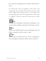
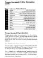
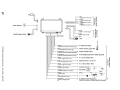
Primary Harness (H1) Wire Connection
Guide
Primary Harness Wiring Diagram
(-) 500 rnA Armed Output
I
(+)1(-) Selectable Light Flash Output
I
IORANGE
IWHITE
(-) Door Trigger Input, Zone 3
I
I
I
(-) Instant Trigger Input, Zone 1
I
IVIOLET
(+) Door Trigger Input, Zone 3
I
IBLACK
(-) Chassis Ground Input
I
(+) Switched Ignition Input, Zone 5
I
(+) Siren Output
I
IWHITE/BLUE
IBLACKIWHITE
(-) 200 rnA Channel 3 Programmable Output
(-) 200 rnA Domelight Supervision Output
IGREEN
IBLUE
IYELLOW
IBROWN
(+) Constant Power Input
IRED
IREDIWHITE
(-) 200 rnA Channel 2 Output
I
I
Primary Harness Wiring Instructions
This guide describes in detail the connection of each wire. Also included are
possible applications of each wire. This system was designed with the ultimate
in flexibility and security in mind. Many of the wires have more than one
possible function. Please read carefully to ensure a thorough understanding
of this unit.
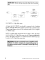
HIll ORANGE (-) ground-when-armed output
This wire supplies a (-) ground as long as the system is armed. This output
ceases as soon as the system is disarmed. The orange wire is pre-wired to control
the 8618 starter kill relay. It can supply up to 500 rnA of current.
NOTE: If using the HIll Orange wire to activate an add-on accessory such
as window automation, or voice module a lAmp diode must be installed to
ensure proper operation. Insert the diode as shown in the following diagram.
© 2008 Directed Electronics- All rights reserved.
4
IMPORTANT! Never interrupt any wireofher thafl the starter
wire.'
PRE-WIRED
STARTER Kill
RELAY
TO OPTIONAL SENSORS,
529T, 530T, ETC,
TO STARTER MOTOR
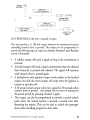
Hl/2 WHITE (+1-) light flash output
As shipped, the HI 12 WHITE wire should be connected to the (+) parking
light wire. If the light flash polarity jumper is moved to the (-) position (see the
Programming Jumper section of this installation guide), this wire supplies
a (-) 200 rnA output.
NOTE: For parking light systems that draw 10 amps or more, the jumper
must be switched to a (-) light flash output (see the Programming Jumpers
section of this guide). PIN 8617 or a standard automotive SPDT relay must
be used on the H1/2 light flash output wire.
IMPORTANT! DO NOT connect this wire to a negative venicle
light flash wire'before ehangillg theprog,ra,mmitlg Jumper to
the negative po'larity .position or,damage to vehicle'ligh.t circuit
may occur.
,
5
© 2008 Directed Electronics- All rights reserved.
PARKING
LIGHT BULB
WHITE H1/2
(+) LIGHT FLASH OUTPUT
~~~~---~~~~C==-=H
....l....-
(+) 12V
I
PARKING LIGHT
RELAY OR SWITCH
DIA-l
WHITE H1/2
(-) LIGHT FLASH OUTPUT
FACTORY PARKING
LIGHT RELAY
PARKING LIGHT
SWITCH
Hl/3 WHITE/BLUE 200 rnA (-) channel 3 output
This wire provides a (-) 200 rnA output whenever the transmitter button(s)
controlling channel three is pressed. This output can be programmed to
provide the following types of output (see System Features Learn Routine
section of this guide):
• A validity output will send a signal as long as the transmission is
received.
• A latched output will send a signal continuously when the channel
three button(s) is pressed and released. The signal will continue
until channel three is pressed again.
• A latched/reset with ignition output works similar to the latched
output, but will also reset (output will stop) when the ignition is
turned on and then off.
• A 30 second timed output will send a signal for 30 seconds when
channel three is pressed. This output can be shut off during the
30-second period by pressing Channel 3 again.
• This output can also be programmed to provide a second unlock
pulse when the unlock button is pressed a second time after
disarming the system. This can be used to unlock the passenger
doors when installing progressive door locks.
© 2008 Directed Electronics- All rights reserved.
6
IMPORTANT! Never use this wire to drive anything but a
relay or a low-current input! This transistorized output can
only supply 200 mA, and connecting directly to a solenoid,
motor, or other high-current device will cause the module to
fail.
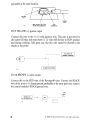
Hl/4 BLACK/WHITE (-) 200 rnA domelight supervision output
Connect the HI /4 wire to the optional domelight supervision relay as shown
in the following diagram:
IMPORTANTl This output is only intended to drive a relay. It cannot be connected
directly to the domelight circuit, as the output cannot support the current draw of one
or more bulbs.
H1/4 BLACKJWHITE
DOMELIGHT SUPERVISION
POLARITY (+) OR (-)
II
86
[!+)
I
11-----------l
i
I
12V CONSTANTFUSED
30
,
1
,--I- - - - - - - - - 1
DOMELIGHT WIRE
Hl/5 GREEN (-) door trigger input
Most vehicles use negative door trigger circuits. Connect the green wire to a
wire showing ground when any door is opened. When connecting to newer
model vehicles there is generally a need to use individual door triggers. See
DirectFax document 1076 for wiring instructions. This wire will report Zone
3.
NOTE: If using a door trigger wire that has a delay, Advanced Menu 2, feature
6 or the 998T Bitwriter can be used to turn Bypass Notification off.
7
© 2008 Directed Electronics- All rights reserved.
DOMELIGHT
~
M~)
I
(-j DOOR SWITCH
_
(\
0-l-----------'------
-'1
DfA_2741r---(+-)1-2-V
Hl/6 BLUE (-) instant trigger input
This input will respond to a negative input with an instant trigger. It is ideal for
hood and trunk pins and will report on Zone 1. It can also be used with Directed
single-stage sensors. The Hl/6 blue instant trigger wire can also be used to shunt
sensors during operation of auxiliary channels or remote start. (See Bypassing
Sensor Inputs section of this guide.)
H1/7 VIOLET (+) door trigger input
This type of dome circuit is used in many Ford products. Connect the violet
wire to a wire that shows (+) 12V when any door is opened. This wire will report
Zone 3.
NOTE: If using a door trigger wire that has a delay, Advanced Menu 2, feature
6 or the 998T Bitwriter can be used to turn Bypass Notification off.
DOMELIGHT
(+) DOOR SWITCH
01A·272
I
(+) 12V
~
bl
• •
lIJ A
I
I
l
H1/8 BLACK (-) chassis ground connection
Connect this wire to a clean, paint-free sheet metal location (driver kick
panel) using a factory bolt that DOES NOT have any vehicle component
grounds attached to it. A screw should only be used when in conjunction with
a two-sided lock washer. Under dash brackets and door sheet metal are not
acceptable ground points. It is recommended that all security components be
© 2008 Directed Electronics- All rights reserved.
8
grounded at the same location.
\
GROUND
WIRE
OIA..a.4
NOTE: REMOVE ANY PAINT
BELOW RING CONNECTOR
RING
CONNECTOR
Hl/9 YELLOW (+) ignition input
Connect this wire to the (+) 12 volts ignition wire. This wire is pre-wired to
the starter kill relay and must show (+) 12 volts with the key in RUN position
and during cranking. Take great care that this wire cannot be shorted to the
chassis at any point.
YELLOW H1/9
PRIMARY HARNESS
TO IGNITION SYSTEM
DlA,37
H1/10 BROWN (+) siren output
Connect this to the RED wire of the Revenger® siren. Connect the BLACK
wire of the siren to (-) chassis ground, preferably at the same point you connect
the control module's BLACK ground wire.
..~
._~~
~~
....
BROWN HMO
(+) 12V SIREN OUTPUT
9
•
RED
I
~
~II
-=1r---......,Ir-B-LA-CK-I----'
© 2008 Directed Electronics- All rights reserved.
HI/II RED (+)12V constant power input
Before connecting this wire, remove the supplied fuse. Connect to the battery
positive terminal or the constant 12V supply to the ignition switch.
NOTE: Always use a fuse within 12 inches of the point you obtain (+)12V.
Do not use the 15 amp fuse in the harness for this purpose. This fuse protects
the module itself.
HU12 RED/WHITE 200 rnA (-) channel 2 output
When the system receives the code controlling channel 2 for longer than 1.5
seconds, the RED/WHITE will supply an output as long as the transmission
continues. This is often used to operate a trunk/hatch release or other relay/
driven function.
IMPORTANT! Never uS9.this wire to drive. anything but a relay
or.alow"currentinputf The transistorized output.can only supply
200mA of current-Connecting directly to a solenoid, motor, or
other high-current deVice will cause it to fan.
I
H1/12 REDIWHITE
(+) 12V IF (+l SWITCHED
(0) GROUND IF (0) SWITCHED
(+) 12V CONSTANT FUSED
SWITCHED TRUNK
RELEASE WIRE
DIA-4
© 2008 Directed Electronics- All rights reserved.
10
Door Lock Harness (H2), 3-PIN Connector
IGreen
IEmpty
IBlue
(-) Lock, (+) Unlock Output
I
Unless Using 451 M
I
(-) Unlock, (+) Lock Output
I
IMPORTANTI The door lock outputs· are .low current and should not
be attached directly to any high current device; they are only to be
used to activate relays.
For detailed instructions about connecting to the vehicle's power door lock
systems, refer to the Door Lock Wiring guide (Document No. 1041) available
to authorized dealers only from the technical resources listed at the front of
this guide.
11
© 2008 Directed Electronics- All rights reserved.
Peripheral Plug-in Harness
Super Bright LED, 2-Pin WHITE Plug
The super bright LED operates at (+) 2 volt DC and plugs into the
two-pin WHITE port. Make sure the LED wires are not shorted to
ground as the LED will be damaged. Multiple LED's can be used, but
they must be wired in series. The LED fits into a 9/32-inch mounting
hole. Be sure to check for clearance prior to drilling the mounting
hole.
NOTE: Never use a BLUE LED in combination with a RED LED.
CONTROL
BLUE
MODULE
RED
L-_------I
DIA-41
© 2008 Directed Electronics- All rights reserved.
12
Valet/Program Switch, 2-Pin BLUE Plug
The Valet/Program button should be accessible from the driver's seat. It plugs
into the BLUE port on the side of the unit. Since the system features Valet®
by using the remote transmitter, the button can be well hidden. Consider how
the button will be used before choosing a mounting location. Check for rear
clearance before drilling a 9/32-inch hole and mounting the button.The GRAY
wire in the two-pin plug may also be used as a (+) ghost switch input and can
be connected to any (+) switch in the vehicle. (See Feature Descriptions
section of this guide.)
VALt I
CONTROL
MODULE
~WlllJH
GRAY
BLACK
~_ _--I
DIA-453
Programmer Interface, 3-Pin BLACK Plug
I!I
~wn--:
13
The BLACK three-pin port connection is for programming the unit.
When using the 998T Bitwritet®, it is possible to configure any and
all of the programmable functions. For more information please refer
to the guide packaged with the programmer.
© 2008 Directed Electronics- All rights reserved.
Mounting the Antenna/Receiver
The antenna/receiver's position should be discussed with the vehicle owner
prior to installation, since it will be visible to to the vehicle's operator.
The best location for the Antenna/receiver is centered high on either the front
or rear windshield. For optimal range, the antenna should be mounted vertically. It can be mounted horizontally in relation to the windshield or under the
dashboard away from metal, but range will be diminished. Metallic window
tint can also affect range, so this should be a consideration when determining
the mounting location.
After determining the best mounting location, follow these steps:
1. Clean the mounting area with a quality glass cleaner or alcohol to remove
any dirt or residue.
2. Plug the Antennalreceiver cable into the Antennalreceiver.
3. Mount the Antennalreceiver using the supplied double-sided tape.
4. Route the Antenna/receiver cable to the control module and plug it into
the four-pin antenna connector.
© 2008 Directed Electronics- All rights reserved.
14
Imj:J~irlt • . r~.~~.i~ye(#l~;,.~$t~$l~I~>5r~~fr~.~~r;t~~ve·.t~~·
ant~tl~f·~~'.;'~f1;/~~Adt~u,,~r.··tf:1e><~~~';'<.4._,~;~~end.t he
cabl~fUU··tEJ,flgth;dltdnQ;jl'l$t8J1ation;;
l0c4tiOrl.·'// ',." ,..'. . " ' . , ......' rega(~I$$$~()ftheanten"aDlOunting
' . ........" .' '.'" ' ' ..'
Antenna receiver cable
On-Board Dual-Stage Shock Sensor
Less Sensitive
More Sensitive
DRW·52
There is a dual-stage shock sensor inside the control unit. Adjustments are
made via the rotary control as indicated in the diagram. Since the shock sensor
does not work well when mounted firmly to metal, we do not recommend
screwing down the control module. The full trigger of the on-board shock
sensor reports Zone 2. (See Table of Zones section of this guide.)
Note: When adjusting the sensor, it must be in the same mounting location
that it will be after the installation is completed. Adjusting the sensor and then
relocating the module requires readjustment.
15
© 2008 Directed Electronics- All rights reserved.
Optional Sensor Harness, 4-pinConnector
The four-pin sensor harness is optional, and is not included with this unit.
RED (+) 12V Constant and BLACK (-) Ground
These wires supply constant (+) 12 volts and ground to the optional sensor.
BLUE/GREEN (-) Multiplex Input
These wires are multiplex inputs. If a (-) input of less than 0.8 seconds is
supplied to either wire, the Warn-Away response will occur. A (-) input of
longer than 0.8 seconds to either wire will initiate the triggered sequence and
report Zone 4.
Programming Jumper
o
o
t"tfl,
®
'l
o
+
TO CHANGE
JUMPER
SETIINGS
LIGHT FLASH JUMPER
(-) LIGHT FLASH OUTPUT _/ __ , (+) LIGHT FLASH OUTPUT (DEFAULT)
Light Flash Jumper
This jumper is used to determine the light flash output. In the (+) position,
the on-board relay is enabled and the unit will output (+)12V on the WHITE
wire, HIll. In the (-) position, the on-board relay is disabled. The WHITE
wire, HII2, will supply a 200 rnA (-) output suitable for driving factory
parking light relays.
© 2008 Directed Electronics- All rights reserved.
16
NOTE: For parking light circuits that draw 10 amps or more, the jumper must
be switched to a (-) light flash output. PIN 8617 or a standard automotive
SPDT relay must be used on the H 1/2 light flash output harness wire.
..
Important! DO. NOT connect .' the H112 ,Hghtflashwire to
a.. . ne~~ti'/e . . . yehiclelight··.·fla$h•.·.··wirEl•.• ··bef~r~ .changing.• the
progrS11'lrning jumper to.theneg~tivepol~ritypos·itionor
damage to vehicle light circuit may occur.
.
'
Bypassing Sensor Inputs
There are times when you need to temporarily bypass all sensor inputs to
the unit, such as when remote starting the vehicle. Anytime an auxiliary
channel output is used, all inputs are bypassed for 5 seconds. During the 5
second bypass period, ground can be supplied to the Hl/6 Blue wire without
triggering the unit.
When the 5 second bypass period ends, if the unit sees ground on the Hl/6
Blue wire, all trigger inputs except the door trigger input will remain bypassed
until 5 seconds after ground is removed from the BLUE wire. The ignition
input needs to be bypassed during remote start also. This can be done using
the status and ignition output of a Directed Electronics remote engine starting
unit as shown in the following diagram:
I
TO OPTIONAL HOODI
TRUNK PINS OR SENSORS
~~_BL_UE_W_IRE_H_'/6_Z_0N_E
'_IN_PU_T---;
REMOTE START UNIT 1----4--{""!-i"Dt~~;--1
(-J During remote
Alarm system
Yellow Hl/9
ignition input
start output
Yellow ignition output
from DEI remote start
17
Starter kill
relay
© 2008 Directed Electronics- All rights reserved,
System Features Learn Routine
The System Features Learn Routine dictates how the unit operates. Due to
the number of steps, they have been broken up into two menus. It is possible
to access and change any of the feature settings using the Valet/Program
switch. However, this process can be greatly simplified by using the 998T
Bitwriter. Any of the settings can be changed and then assigned to a particular
transmitter, up to four, a feature called Owner Recognition. Each time that
particular transmitter is used to disarm the system, the assigned feature settings
will be recalled. Owner Recognition is only possible when programming the
unit via the 998T Bitwriter.
If the system was previously programmed using the 998T Bitwriter, the learn
routine may be locked. If the siren generates one long chirp when attempting
to program the unit, the learn routine is locked and must be unlocked using
the 998T Bitwriter.
1.
Open a door. (The Hl/5 GREEN wire or the HI/?
VIOLET wire must be
connected.)
2.
Ignition. Turn the ignition on, then back off: (The
Hl/9 YELLOW wire must be connected.)
Select a Menu. Press and HOLD the Valet/Program
switch: (The Valet/Program switch must be plugged
into the blue port.) After three seconds the siren will
chirp once indicating entry to the Basic Features Menu
#1. If this is the menu you wish to access, release the
button and go on to Step 4. If the button is not
released, you will jump to the Advanced Features Menu
#2 and the siren will chirp twice. Once you have
selected the desired menu, release the Valet/Program
button and then proceed to Step 4.
© 2008 Directed Electronics- All rights reserved,
18
4.
Select a Feature. Press and release the Valet/Program
switch the number of times corresponding to the feature
you wish to change. For example, to access the third
feature, press and release the switch three times. Then
press the switch once more and HOLD it. The siren
will chirp the number of times equal to the step you
have accessed.
1I1~~0~
\. '
v.
\
DRW·35 /
'~
I
!
I
Jj
5.
Program the Feature. While holding the Valetl
Program switch, you can toggle the feature on and off
using the remote transmitter. Pr~~,sing l-~I:: will select
the one chirp setting. Pressing ~sr: will
select the two chirp setting.
(See Systems Features menus)
NOTE: The Valet pulse count feature (2-5) and the
Channel three timed o.l!~put (2-9) have five possible
settings each. Pressing lrf: will toggle through all the
two-chirp settings.
6.
•
•
•
•
19
Release the Valet/Program Switch.
Once a feature is programmed:
Other features can be programmed within the same menu.
Another menu can be selected.
The learn routine can be exited if programming is complete.
© 2008 Directed Electronics- All rights reserved.
To access another feature in the same menu:
•
•
Press and release the Valet/Program switch the number of times necessary
to advance from the feature you just programmed to the next one you
want to program.
Then press the Valet/Program switch once more and HOLD it.
For example, if you just programmed the third feature in the menu and you
would like to program the seventh feature in the menu, you would press and
release the Valet/Program switch four times and then press it once more and
hold it. The siren would chirp seven times to confirm access to the seventh
feature.
To select another menu:
•
•
Press and hold the Valet/Program switch.
After three seconds, the unit will advance to the next menu and the siren
will chirp, indicating which menu has been accessed.
For instance, ifyou just programmed some features in Menu #1 (Basic Features)
and you wish to program a feature in Menu #2, you press and HOLD the
Valet/Program button. After three seconds, the siren chirps twice indicating
access to Menu #2.
To exit the learn routine do one of the following:
•
•
•
•
Close the open door.
Turn the ignition on.
No activity for longer than 15 seconds.
Press the Valet/Program switch too many times.
© 2008 Directed Electronics- All rights reserved.
20
System Features Menus
Menu #1 - Basic Features
Items in bold text have been programmed to the default setting at the factory.
One Chirp
Setting
Two-Chirp
Setting
1-1
Active arming
Passive arming
1-2
Chirps ON
Chirps OFF
1-3
Ignition controlled door locks ON
Ignition controlled door locks OFF
1-4
Active locking only
Passive locking
1-5
Panic with ignition on
No panic with ignition on
1-6
0.8 second door lock pulses
3.5 second door lock pulses
1-7
Forced passive arming ON
Forced passive arming OFF
1-8
Automatic Engine Disable ON
Automatic Engine Disable OFF
1-9
Armed When Driving (AWD)
Vehicle Recovery System (VRS)
1-10
Code Hopping'" on
Code
Feature
Number
21
HoppingT~
off
© 2008 Directed Electronics- All rights reserved.
Menu #2 - Advanced Features
One Chirp
Setting
Two-Chirp
Setting
2-1
Siren
Horn honk
2-2
3O-second siren duration
60-second siren duration*
2-3
Nuisance Prevention- Circuitry ON
Nuisance Prevention- Circuitry OFF
2-4
Progressive door trigger
Instant door trigger
2-5
Valet switch Input: 1 pulse
Valet switch input: 2-5 pulses
2-6
Bypass Notification ON
Bypass Notification OFF
2-7
Ignition-controlled domelight ON
Ignition-controlled domelight OFF
2-8
Single unlock pulse
Double unlock pulse
2-9
Single lock pulse
Double lock pulse
2-10
Channel 3: Validity
Channel 3: latchedllatched, reset
with ignition/3D-second timed!
second unlock output·
2-11
Comfort Closure (On) (20 sec.)
Comfort Closure (Off)
Feature
Number
*The Bitwriter allows programming from 1-180 seconds.
*Second unlock is only available if Feature 2-8 is programmed to single pulse.
Feature Descriptions
The features of the system are described below. Features that have additional
settings that can be selected only when programming with the 998T Bitwriter
are indicated by the following icon:
II
Menu #1 - Basic Features
1-1 ACTIVE/PASSIVE ARMING: When active arming is selected, the
system will only arm when the transmitter is used. When set to passive, the
system will arm automatically 30 seconds after the last door is dosed. To alert
the consumer of passive arming, the siren will chirp 20 seconds after the door is
dosed. This provides the consumer with an audible prior to the system actually
arming. At the 30 second mark, the system will arm but the siren will not
chirp.
1-2 Chirps ON/OFF: This feature controls the chirps that confirm the
arming and disarming of the system.
© 2008 Directed Electronics- All rights reserved.
22
·.. 1-3 IGNITION CONTROLLED DOOR LOCKS ON/OFF:
•
When turned on, the doors will lock three seconds after the ignition is
turned on and unlock when the ignition is turned off. The 998T
Bitwriter will display separate steps for ignition lock and ignition unlock. They
can be programmed on or off independently.
1-4 ACTIVE/PASSIVE LOCKING: If passive arming is selected in
step 1-1, then the system can be programmed to either lock the doors when
passive arming occurs, or only lock the doors when the system is armed via the
transmitter. Active locking means the system will not lock the doors when it
passively arms. Passive locking means that the system will lock the doors when
it passively arms.
NOTE: Remember, when passive arming is selected, the unit will chirp 20
seconds after the last door is closed. The system does not actually arm or lock
the doors until 30 seconds after the door has been closed.
1-5 PANIC WITH IGNITION ON: This step controls whether or not
the Panic Mode is available with the ignition on. In some states, there are laws
prohibiting a siren from sounding in a moving vehicle. This feature makes the
system compliant with these regulations.
1-6 DOOR LOCK PULSE DURATION: Some European vehicles,
such as Mercedes-Benz and Audi, require longer lock and unlock pulses to
operate the vacuum pump. Programming the system to provide 3.5 second
pulses, will accommodate the door lock interface in these vehicles. The default
setting is 0.8 second door lock pulses.
1-7 FORCED PASSIVE ARMING ON/OFF: To use this feature,
passive arming must be selected in step 1-1. When turned on, forced passive
arming will ensure that the system will passively arm, even if a zone is left
open or invalid. Forced passive arming occurs one hour after the ignition is
turned off.
23
© 2008 Directed Electronics- All rights reserved.
1-8 AUTOMATIC ENGINE DISABLE (AED) ON/OFF: AED is
a full-time, passive starter disable that works independently of the security
system. When turned on, the orange, ground-when-armed output (H 1/1) will
go active 30 seconds after the ignition is turned off. The LED will flash at half
its normal rate when the ignition is turned off to indicate that AED is active
and will interrupt the starter in 30 seconds. AED does not occur in Valet mode
and can be bypassed using the emergency override procedure. The transmitter
can also be used to disarm AED.
1-9 ARMED WHILE DRIVING/VEHICLE RECOVERY SYSTEM:
In the default setting (Armed While Driving), the system can be armed with
the ignition on. When armed, the ground-when-armed is not active and the
sensors are bypassed. The door triggers will remain active. If programmed to
the Vehicle Recovery System (VRS®) setting, VRS® will be activated.
1-10 CODE-HOPPINGTM ON/OFF: The system uses a mathematical
formula to change its code each time the transmitter and receiver communicate.
This makes the group of bits or "word" from the transmitter very long. The
longer the word is, the easier it is to block its transmission to the unit. Disabling
the Code-Hopping™ feature lets the receiver ignore the Code-Hopping™
part of the transmitted word. As a result, the unit may have better range with
Code-HoppingTM off.
Menu #2 - Advanced Features
2-1 SIREN/HORN HONK: The system can be programmed to output
pulses instead of a continuous output when the system is triggered. This is
useful to honk the factory horn in applications where a siren is undesirable.
Remember that the unit is only capable of supplying 1 amp of current. A relay
will be required to interface with most factory horn systems.
2-2 SIREN DURATION 30/60 SECONDS: It is possible to
.program the unit to sound for 30 or 60 seconds during the triggered
sequence. Some states have laws regulating how long a security system can
sound. When using the 998T Bitwriter, the siren can be programmed to sound
for any length of time ranging from 1 to 180 seconds. Using the SELECT
button of the 998T Bitwriter will adjust the siren duration in one second increments.
© 2008 Directed Electronics- All rights reserved.
24
2-3 NUISANCE PREVENTION® CIRCUITRY (NPC®) ON/
OFF: NPC® stops repeated triggering of the same zone. If one zone is
triggered three times in one hour, that zone is bypassed for one hour, starting
from the time of the third trigger. During that hour, if the system detects a
trigger on that zone again, the system resets the one hour timer. If one hour
passes and the zone has not triggered again, the zone is activated and can trigger
the system again. NPC® monitors sensor inputs and the door trigger, but does
not bypass the ignition trigger at any time. If NPC® is turned off, the system
will respond to repeated triggers on the sensor inputs and will do so indefinitely. Some states have laws regulating how many times a security system can
trigger before it is considered a nuisance and the vehicle is towed away.
2-4 PROGRESSIVE DOOR TRIGGER ON/OFF: The system responds
to a door trigger input with a progressive response. When the door is opened
with the system armed, the siren will chirp 10 times prior to the full triggered
sequence. The door trigger is still treated as an instant trigger and closing the
door quickly will not prevent a full triggered sequence from occurring. If the
progressive door trigger is programmed off, the full siren output will occur the
moment the door is opened.
2- 5VALET PULSE COUNT ONE TO FIVE PULSES: The system can
be programmed to count the number presses ofthe valet button before disarming
the security system or VRS®. The factory default setting is one pulse. The unit can
be set for two to five pulses using the two-chirp setting to select the pulse count.
Ghost Switch Option: For added security, the GRAY wire on the two-pin
Valet/Program can be connected to any switch in the vehicle that provides a
positive (+) momentary pulse.
2-6 Bypass Notification ON/OFF: when programmed on, any active zone
input to the system during arming will generate a bypass notification chirp.
When programmed OFF, no bypass notification chirps will be generated if any
zone is active during arming.
2-7 Ignition-controlled DOMELIGHT SUPERVISION ON/OFF:
If turned on, the system will turn on the domelight for 30 seconds when the
ignition is turned off. The optional domelight supervision feature must be
installed.
25
© 2008 Directed Electronics- All rights reserved.
2-8 DOUBLE PULSE UNLOCK ON/OFF: Some vehicles require two
pulses on a single wire to unlock the doors. When the double pulse unlock
feature is turned on, the BLUE H2/C wire will supply two negative pulses
instead of a single pulse. At the same time, the GREEN H2/A wire will supply
two positive pulses instead of a single pulse. This makes it possible to directly
interface with double pulse vehicles without any extra parts.
2-9 Double/Single Pulse Lock: Some vehicles require two pulses on a single
wire to lock the doors. When the double pulse lock feature is turned on, the
BLUE H2/C wire will supply two positive pulses instead of a single pulse. At
the same time the GREEN H2/A wire will supply two negative pulses instead
of a single pulse. This makes it possible to directly interface with double pulse
vehicles without any extra parts.
2-10 CHANNEL 3 VALIDITY/LATCHED/LATCHED RESET WITH
IGNITION/3D SECOND TIMED/SECOND UNLOCK OUTPUT:
Channel 3 can be programmed for these output configurations. The unit is set
to the default validity output. To change the configuration use the two-chirp
setting to toggle to the different configurations.
2-11 COMFORT CLOSURE: The system can be programmed to close the
windows when the system is armed. A 20-second output starts 200mS after th~
last J~_: button pulse. The comfort closure output will be cancelled if the 1£:
button is pressed. If programmed ON, the lock output wire will provide this
function.
NOTE: Comfort closure is deleted if one-time bypass is activated.
© 2008 Directed Electronics- All rights reserved.
26
Transmitter/Receiver Learn Routine
The system comes with two transmitters that have been taught to it. The
system can store up to four different transmitter codes in memory. Use the
following learn routine to add transmitters to the system or to change button
assignments if desired.
If the system was previously programmed using the 998T Bitwriter, the learn
routine may be locked. If the siren generates one long chirp when attempting
to program the unit, the learn routine is locked and must be unlocked using
the 998T Bitwriter before proceeding.
Open a door. (The GREEN wire, Hl/5, or the
VIOLET, HI/? must be connected.)
2.
Turn the ignition on. (The YELLOW wire, HI/9 must
be connected.)
Select the receiver channel: Press and release the
Valet/Program button the number of times necessary
to access the desired channel.
NOTE: If adding a remote, a button must be taught to the unit in the Channel
1 or Channel 5 position prior to programming other channels.
Press and hold the Valet/Program button once more. The siren will chirp
and the LED will blink the number of times corresponding to the channel
accessed.
27
© 2008 Directed Electronics- All rights reserved.
Channel Number
1
2
3
Function
Arm/Disarm
Panic only
Silent Mode/Remote ValetlTrunk Release
Remote Start or other accessories
Arm only
Disarm only
Auto-learn standard configuration*
(four-button transmitter)
Auto-learn three-button configuration*
Delete all transmitters
4
5
6
7
8
9
Wire Color
RED/WHITE
WHITE/BLUE
*NOTE: For Auto Learn Configurations, see Transmitter Configurations section of this
guide.
IIi~i:~'1
~x)
/
..'
~
4. Press the transmitter button: While holding th,e Valetl
Program button, press the button from the transmItter that
you wish to assign to the selected channel. The unit will chirp
indicating successful programming, It is not possible to teach
a transmitter button to the system more than once.
Channels #2, 5, 6: Channels 2, 5, and 6 are used to assign the arm, disarm
and panic functions to separate buttons on the remote control. Teaching a
button to Channel 5 or Channel 1 erases some information about that remote
from memory, and auxiliary functions that are desired may have to be reprogrammed.
Channel #9: If any button from a known transmitter is programmed to
Channel 9, all transmitters will be erased from memory and the system
features will revert to the default settings. This is useful in cases where the
one of the customer's transmitters is lost or stolen. This will erase any lost or
stolen transmitters from the system's memory. It can also be used to start from
scratch if the transmitter buttons were programmed incorrectly.
© 2008 Directed Electronics- All rights reserved.
28
~
5. Release. Once the code is learned, the Valet/Program button
can be released.
To exit the learn routine:
One long chirp indicates that Learn Routine has been exited. Learn Routine
will be exited if any of the following occurs:
•
•
•
•
29
Ignition is turned off.
Door is dosed.
Valet/Program button is pressed too many times.
More than 15 seconds elapse between steps.
© 2008 Directed Electronics- All rights reserved.
Transmitter Configurations
The transmitters can be programmed with the standard or three-button
configurations by using the Auto Learn functions in the TransmitteriReceiver
Learn Routine.
Standard Configuration
When programmed for standard configuration, the transmitter buttons are
assigned to th~Jollowing functions:
'
''.
.',.·8.·
,.,:-
",
I
'."i
operates
Arm only
operates
Disarm only
operates
Channel 2 and Silent Mode
'Af
...n'. '.
Panic
operate
Channel 3
Three-button configuration - Optional not included
'SAIr··' operates
i·
"
I'r.,
-,
,
..•
,
,._--_._._-----------_._--- __ .._',
ilUI:
,L
..
'•
Arm/Disarm
operates Channel 2 and Silent Mode
NOTE: Multi Level Security Arming feature is not available with the threebutton.
© 2008 Directed Electronics- All rights reserved.
30
Diagnostics
The system's microprocessor monitors and reports all active and violated zones
when arming and disarming. LED flashes indicate the active or violated zone;
siren chirps indicate system status.
Arm/Disarm Diagnostics
The number of siren chirps will indicate the status of the alarm when arming
and disarming. For information on which zone is active or has been violated
refer to the Table of Zones.
System Status Chirps
Number of Chirps
Description
Arm
1
System armed
Arm
1 (3 second delay), 1
System armed with Bypass Notification
Disarm
2
System disarmed
Disarm
4
System disarmed with Tamper Alert
Disarm
5
System disarmed NPC® active
Action
31
© 2008 Directed Electronics- All rights reserved.
Table of Zones
Zone No. Trigger type
Input description
1
Instant
H1/6 BLUE - Connect to optional hood/trunk
pins.
2
On-board shock sensor
Heavy impact detected by the on-board shock
sensor.
3
Two-stage, progresses from
Door switch circuit. H1/5 GREEN or H1/7
VIOLET warning to full alarm
4
Multiplexed Input
BLUE and GREEN wires of optional sensor
plug. Inputs shorter than 0.8 seconds will trigger
a Warn Away response, while inputs longerthan
0.8 seconds will instantly trigger a full alarm
sequence and report Zone 4.
5
Two-stage (similar to doors)
Ignition input. H1/9 YELLOW.
NOTE: The Warn Away® response does not report on the LED.
Long Term Event History
The system stores the last two full triggers in memory. These are not erasable.
Each time the unit sees a full trigger, the older of the two triggers in memory
will be replaced by the new trigger. To access long term event history:
1. With the ignition off, press and HOLD the Valet/Program
switch.
2. Turn on the ignition.
3. Release the Valet/Program switch.
© 2008 Directed Electronics- All rights reserved.
32
4. Press and release the Valet/Program switch within 5 seconds.
The LED will flash in groups indicating the last two zones that
triggered the unit. The LED will flash for one minute or until
the ignition is turned off.
NOTE: The Warning Zone triggers are not stored to memory and will not be
reponed.
Multi-Level Security Arming
Multi-Level Security arming allows the operator to select which inputs and
sensors are active during a particular arming cycle. For a full description of
Multi-Level Security Arming operation for testing purposes refer to the owner's
manual.
33
© 2008 Directed Electronics- All rights reserved.
Optional Vehicle Recovery System (VRS)
VRS is an optional feature designed to disable a vehicle during a carjacking
event. It must be programmed in the features menu and the Failsafe Starter
Kill must be installed for it to work properly. For operational instructions when
testing VRS refer to the owner's manual.
Nuisance Prevention® Circuitry
Nuisance Prevention Circuitry bypasses any zone that triggers the system more
than three times within a one hour period. For a full description ofNPC operations refer to the owner's manual.
IMP()RTANT:•.Wilen. testing', tt\e·.s~Stern$ ··setlsor .•a[1d ··;ttiggerinpUts
resetNPC,tiywtnif'lg ()ntbe·ignjtionaf!erevef!Ythh'd:,~y.stenltrigger.
.
Rapid Resume Logic
Rapid Resume Logic ensures that the when the system is powered up it will
return to the same state it was in when power is disconnected. For a full
description of Rapid Resume Logic refer to the owner's manual.
© 2008 Directed Electronics- All rights reserved.
34
Troubleshooting
Starter kill doesn't work.
•
•
Is the correct starter wire being interrupted? If the car starts when the
starter kill relay is completely disconnected, the wrong starter wire has been
cut and interrupted.
YELLOW wire is not connected to true ignition. It is connected to an
accessory CIrCUIt.
Shock sensor doesn't trigger the alarm.
•
Has the NPC@ system been triggered? If so, you will hear five chirps when
disarming. To check this, turn the ignition key on and off to clear the NPC®
from memory, and then retest the shock sensor. For a detailed description of
NPC@, see Owner's Guide.
Door input does not immediately trigger full alarm. Instead, I hear
chirps for the first three seconds.
•
That's how the progressive two-stage door input works! This is the instant
response feature of this system. Even if the door is closed immediately, the
system provides an instant trigger by chirping, and the progressing to a
constant SIren.
Closing the door triggers the system, but opening the door does not.
•
35
Have you correctly identified the type ofdoor switch system? This happens
often when the wrong door input has been used.
© 2008 Directed Electronics- All rights reserved.
System will not passively arm until it is remotely armed and then
disarmed.
•
Are the door inputs connected? Is a blue wire connected to the door trigger
wire in the vehicle? Either the green HI /5 or the violet HI /7 should be
used instead.
Door input does not respond with the progressive trigger, but with
immediate full alarm.
•
What zone does the LED indicate? If the LED indicates that the impact
sensor caused the trigger, the sensor may be detecting the door opening.
Reducing the sensitivity or relocating the sensor can often solve this
problem. If the LED indicates that the door caused the trigger, you may
have programmed the progressive door trigger off. (See Feature 2-4 in the
Feature Descriptions section of this guide.)
The Valet button doesn't work.
•
Is it plugged into the correct socket? Check the System Features Learn
Routine for the programmed Valet pulse count.
Status LED doesn't work.
•
Make sure that it is plugged in. (See Plug-In Harnesses section of this
guide.) Is the LED plugged into the correct socket?
© 2008 Directed Electronics- All rights reserved.
36
(,,)
...-..
99BT Bitwriter-
~-
o
o
... D
~ -------10-.
VslerJProg""" S.,'ch
J-
'I
I
V)
(+) Constant Power Input
RED
]
BLACK
H Chassis Ground Input
BLUE
(-) Multiplex input, Zone 2
GREEN
(-) Multiplex input, Zone 4
~~
gE;
c55~
e:: .....
.- 0
Q..V)
'e::
"l'Q)
U)
...
.....
C§~
GREEN
(-) Lock, (+) Unlock Output ]
o
+
@E;
,J::
~qs
Empty
(Unless Using a 451 M)
+
Light Flash
Jumper
~13
BLUE
(-) Unlock, (+) Lock Output
'- 0
~-J
LED
~
~
~
(-) 500 mA Ground-When-Armed Output
@
N
o
o
~
o
.....
C'D
n
<t>
..-+
0-
m
<t>
n
l...--
WHITE
(+)/(-) Selectable Light Flash Output
•
' - - - - WHITE/BLUE
•
(-) 200 mA Channel 3 Programmable Output
L..--
:::)
n
en,
»
Vehicle Parking Light Wire
(j)
Programmable Output
BLACKIWHITE
•
(-) 200 mA Domelight Supervision Output
To Oomelight Supervision Relay (Optional)
GREEN
(-) Door Trigger Input, Zone 3
To (-) Door Switch Wire
•
~
...... E;
BLUE
::;:-:;:::::-----=-- 1- - - (_) Instant
Trigger Input, Zone
•
Optional Hood or Trunk Pin
:::r:qs
VIOLET
(+) Door Trigger Input, Zone 3
•
To (+) Door Switch Wire
~E
BLACK
(-) Chassis Ground Input
•
Chassis Ground
YELLOW
(+) Switched Ignition Input, Zone 5
•
Key Switch
BROWN
(+)SirenOutput
RED
(+) Constant Power Input
•
Siren 0
Red
~
..-+
.....
o
~
To Starter Kiff Relay
L.- ORANGE
®
0
0
=t=
-
co
:::T
..-+
en
.....
<t>
en
•
<t>
<:
<t>
0-
REDIWHITE
Channel 2 Validity Output
(M
i
I)
•
~~
'qs
&:
I
Black
~\
~"....
~.••• ~)
>.'.'q.,
. .[).b",,_ .
.
'-.~
To Vehicle Trunk Release or
Optional Accessory (Relay May Be ReqUired)
~
Designed and Engineered in the USA
E LEe T RON I
C 5
N3305P 2008- 12
Vista, CA 92081
www.directed.com
© 2008 Directed Electronics. - All rights reserved.
LID305PO
This product is covered by one or more of the following U.S. patents:
303,223
340,000
352,685
4,383,242
4,897,630
5,193,141
5,534,845
5,798,71 I
5,952,933
333,633
344,905
383,689
4,438,426
4,922,224
5,245,694
5,572,185
5,872,519
5,990,786
333,634
345,317
383,690
4,553,127
4,987,402
5,285,186
5,646,591
5,900,806
6,093,979
333,635
345,711
390,830
4,584,569
5, I03,.2.2.1
5,315,285
5,656,.997
5,907,195
333,636
347,190
392,944
4,794,368
5,117.,217
5,357,560
5,1.12,638
5,914,667
333,795
348,622
4,327,444
4,887,064
5,132,660
5,532,670
5,783,989
5,945,936
International Patents:
Australia:
694,925
Canada:
I,3 15,859 and 2,067,099
Taiwan:
91817
Other patents pending
MKG-I
7/00
LADDEIN7
_~·.7*mftf$W;fllIJ!."'ll,l~!!W'1·mJ.·tJl!t·II).J•. £1.}21,1 J.! ..IUIlJIL••. tWJ,.J •....•JHL.,JS'· . '. IIIJ.11FWI.·!I!IllijJLJJJ...JIIJ.. EJJI.... mJJJJu.rr>'ilo/SWWi/$ ..J;!!.•JU.Il!.J'.)·U:\!i!!$A···J1vi·WW~•.. .
IMPORTANT!
1.1.0
Mr.
3. ~ Ms.
2.0 Mrs.
IMPORTANT!
Ple8se complete and return within the next 10 days
or register online at www.prodregister.com/directed
ELECTRONICS, INC.
4.0 Miss
Firsl Name
Initial
...
XFG01-01
laslName
Streel
Apt. No.
City
Stale
liP Code
E'mail
2.
13.
/
Your dale 01 birth:
Y."
Month
3.
Marital status: 1.::::::i Married
4.
Dale 01 purchase:
/
Month
2. C Single
=
/
Day
Yea,
5.
Model number:
6.
Name of store where purchased:
7.
Price paid (excluding sales tax):
8.
Which Directed Eleclronlcs product did you purchase?
01. C AuloCommand Security System with Remote Start
02 CJ AutoCommand Remote Start System
03. r Avital Security System
04.
Avital Security System with Remote Start
05. :J Avital Remote Start Syslem
06.
Boa Security System
07. :J Boa Remote Start System
08.
Boa Keyless EntrySyslem
09. C Boa Garage Parking Sensor System
10. C Clifford GPS Tracking System
11. C Clifford Security System
12. C Clifford Security Syslem with Remote Start
13. C Clifford Remote Start System
14. C Clifford Keyless Enlry System
15.
Directed Electronics Inc.. Security Accessory
16. :J Directed Electronics Inc., Parking Sensor System
17.
First Defense Security System
18.
Hornet Security System
19.
Hornet Security System with Remote Start
20.
Merlin Security System
21.
Python GPS Tracking System
22.
Python Security System
23.
Python Security System with Remote Start
24.
Python Remote Start System
25.
Python Keyless Entry System
26.
Ready Remote Start System
27.
Valel Remote Start System
28.
Valet Keyless Entry System
Viper GPS Tracking System
29.
Viper Security System
30.
31.
Viper Security System with Remote Start
32.
Viper Remote Start System
33.
Viper Keyless Entry System
34. :J Wasp Securily System
$
14.
What ofher brands did you seriously consider before making
this purchase?
1. 0 None, only this brand 5. 0 Bulldog
2. 0 Other Directed Brands 6. 0 Ungo
only
7.0 Alpine
3. 0 Code Alarm
8. 0 Crime Stopper
4 0 BlackWidow
15.
Which 01 the lollowing publicafions doyou read regulatly
(three oul 01 fhe last lour issues)? (check aN thaI apply)
01 0 Car and Driver
11.0 Road & Track
02.0 Car Audio and
12. :J RollingStone
Electronics
13. ::J SKATEboarding
03. 0 Car Sound and
14. ::J Ski
Performance
15. 0 Snowboard
04. 0 Hal Boat
16.0 Spin
05. 0 Import Tuner
17. C2 Sport Compact Car
06. C Import Racer
18. 0 Sport Truck
07.
lowrider
19 0 Street Trucks
08. :::J Mini Truckin'
20. C SuperStreel
Truckin'
09. 0 Motor Trend
21.
10. C Pertormarx:eAuto 22. 0 Working Woman
& Sound
23. 0 Other
.00
~.
-~
-
-c::
9.
Whaltype 01 vehicle will this produclbe used In1
1. C C"
6 C Motorcycle
2 :J Truck
7 CJ Boat
3.
SUV
8 CJ Molorhome
4
9. 0 Other
V"
5.
MiniVan
16. Not including yourse", what is the GENDER and AGE lin years)
01 children and olheradults living in your household?
1,:::J No one else in household
2. 0 Child under 1year
Male Female
17.
18.
-
1D.
In whal vehicle will lhls produci be used?
Make 01 vehicle:
Model name:
12,
Whallactors most influenced the purchase? (cfled( up 10 three)
01. LJ Directed's reputation 10. 0 Rebate/Promotion
02. ,"J Brand'sreputalion
11. 0 Style/Design/Color
03. !:J Experiencewith
12 [] Dealerproximily
Directed product
13.0 Friend's
04. 0 Experience with dealer
recommendation
05. C Value/Price
14. 0 Salesperson
06. [j Warranty
recommendation
07. _ Special features
15.0 Easeolinstallation
08
Quality/Durability
16. 0 Compatibility with
09. ,-, Sound boardlin'vehicle
vehicle
demo
17. [j Dlher
Age
1.0 2. .::::J
yrs.
1.0 2.0
yrs
1.02.0
yrs.
Occupation: (check alllhal apply)
ProfessionallTechnical...
Upper ManagemenVExecutive ...
Middle Management..
SalesJMarketing.
Clerical/Service Worker ...
Tradesman/Machine Operator/laborer ...
You
Are you or your spouse:
A Homemaker? ..
Retired? ..
AStudent? ..
Self EmployedlBusiness Owner? ..
Working from a Home Office? ...
In the Military? ..
AVeleran? ...
You
Spouse
0
1
0
2.
0
0
0
0
0
0
3.
0
4.
0
5
0
6.
0
Spouse
o
,. 0
2.
0
030
o 4. 0
o
o
o
o
5.
6.
0
0
7.
0
20.
level 01 education: (check highest level completed)
1. 0 Completed High School
2. C Completed College
3. 0 Completed Graduate School
21.
Which credll cards do you use regularly?
1. 0 American Express, Dlnets Club
2. 0 MasterCard, Visa. Discover
3. 0 Department Store, Oil Company, etc.
4.0 Donolusecreditcards
22.
For your primary residence, do you:
1. 0 Own?
2. 0
23.
Please tell us how many magazines your household:
A.
B. Purchasesal
Subscribes 10
Slores/Newsslands
1. 0 1-3 per month
1.0 1-3permonth
2.0 4+permonth
2
4+ per month
Pc C Bought New
8.
Bought Used
C. C leased
o. :J leased Used
How did you fil1l become aware ollhis product? (checkone)
01.
local newspaper
07. C Radio commercial
02.
Yellow pages
08.
Salesperson's
Magazine
03.
recommendation
advertisement
09 C Motorsports
04.
TV commercial
sponsorship
05.
Magazine article/
10. 0 Internet
review
11. '! Other
06. w Friend/Relative's
recommendation
Male Female
yrs.
Which group describes your annuallamlly income?
01. 0 Under 515,000
08. C 575,000-$99,999
02. 0 S15,OOO~S19,999
09. C 5100,000-5124,999
03. ::::; S20.000-$29,999
10. 0 $125.000-S149,999
04. 0 $30,000-$39,999
11. 0 S15O,000-5174.999
OS. 0 $40,000-$49,999
12. 0 5175,OOO-S199,999
06. 0 $50.000-559.999
13. 0 S200.000-5249.999
07. 0 $60,000-574,999
14. 0 $250,000 & over
=
11.
Age
1.0 2.0
19.
VINI:
Year:
What benelits of this producl mosl inlluenced your decision 10
purchase? (check l.Jl to three)
01. 0 ImprOVed security
12 0 Functionality
02. 0 Improved convenience 13. 0 Warranty
03. 0 Improved performaoce 14. C PriceNalue
04. :::J Ability to watch video 15.
RebafeIPromotion
in vehicle
16.
Immediate
availability
05.
Used by autosound
competitors
17.0 Friend's
06. 0 Compatibility with
recommendation
vehicle
18.0 Salesperson
07.0 Ease of installation
recommendation
08. 0 Style/Design/Color
19 0 Dealerproximily
09. 0 Special Features
20 0 Other
10. 0 Quality/Durability
11.0 Increase vehicle vatue
Rent?
o
PLEASE CONTINUE ON BACK
~ ~ ~
24.
Which of the following do you plan to do wilhin Ihe next
6 or 12 months?
1.6
7.12
Months
Months
Buy/Lease a New Vehicle
0
1.
0
Buy/Lease a Used Vehicle
0
2.
0
25.
Please check all that apply to your household.
01. 0
02. 0
03. 0
04. 0
05. 0
06. 0
26.
Shop by Catalog/Mail
Shop via the Internet
Member of Frequent Flyer Program
Donate to Charitable Causes
Own a Compact Disc Player
Have a Dog
Have a Cat
Own aWireless/Cellular Phone
Subscribe to an Online/Internet Service
Speak Spanish
Home Workshop/Do-It-Yourself
To help us understand our customers' lifestyles, please indicate the interests and activities in which you or your spouse
enjoy participating on a regular basis.
Home life
01. 0 Grandchildren
02. 0 Needlework/Knitting
03. 0 Sewing
04. 0 Flower Gardening
05. 0 Vegetable Gardening
06. 0 Crafts
07. 0 Automotive Work
08. 0 Photography
09. 0 Home Video Recording
10. 0 Pay Bills Online
Good Life
11. 0 Cultural/Arts Events
12. 0 Fashion Clothing
13. 0 Foreign Travel
14. 0 Cruise Ship Vacations
15. 0 Travel in USA
16. 0 Gourmet Cooking/Fine Foods
17. 0 Wines
27.
07. 0
08. 0
09. 0
10. 0
11. 0
18. 0 Self-Improvement
19. 0 Watching Sports on TV
20. 0 NASCAR
Investing & Money
21. 0 Real Estate Investments
22. 0 Stocks/Bond Investments
23. 0 Contests/Sweepstakes
24. 0 Casino Gambling
25. 0 Moneymaking Opportunities
Sports, Fitness & Health
26. 0 Bicycling
27. 0 Golf
28. 0 Physical Fitness/Exercise
29. 0 Running/Jogging
30. 0 Snow Skiing
31. 0 Tennis
32. 0 Health/Natural Foods
33. 0 Dieting/Weight Control
34. 0 Walking for Health
Great Outdoors
35. 0 Camping/Hiking
36. 0 Fishing
37. 0 Hunting/Shooting
38. 0 Power Boating
39. 0 Sailing
40. 0 Recreational Vehicles (RVs)
41. 0 Wildlife/Environmental Issues
Hobbies &Inleresls
42. 0 Buy Prerecorded Videos/DVDs
43. 0 Listen to RecordslTapes/CDs
44. 0 Avid Book Reading
45. 0 Bible/Devotional Reading
46. 0 Art/Antique Collecting
47. 0 Stamp/Coin Collecting
48. 0 Collectibles
49. 0 Our Nation's Heritage
50. 0 Electronics
51. 0 Science Fiction
52. 0 Science/ New Technology
Using Ihe numbers in the above list, please indicate your 3 most important activities:
Thanks for taking the time to fill out this questionnaire. Your answers will be used for market research studies and reports. They will also allow you to receive
important mailings and special offers from a number of fine companies whose products and services relate directly to the specific interests, hobbies, and other
information indicated above. Through this selective program, you will be able to obtain more information about activities in which you are involved and less about
those in which you are not. Please check here if, for some reason, you would prefer notto participate in this opportunity. 0
Failure to return this card will not diminish your warranty rights.
Copyright © 2005 All Rights Reserved
540-0070 (A)
Please seal with tape. Do not staple.
LRDEI005
Please send products and other
correspondence to:
First-Class
Postage
Required
Post Office will
not deliver
without proper
postage.
Directed Electronics Inc.
1 Viper Way
Vista, CA 92081
XFG01-01
®
E L E C T RON I C 5, I N
c.
PO BOX 174391
DENVER CO 80217-4391
IIIIIIIIIIIIIIIIIIIIIIII IIIIIIIIIIIIIIIIIIIIIIIIIIIII IIIIIIIII
PRODUCT REGISTRATION
E L E C T RON I C S,
INC.
Security
RETURN THIS CARD NOW FOR:
• Product Protection
With the information you provide we can confirm the date of purchase of your product.
This confirmation is of benefit to you, especially if your original proof of purchase is lost.
• Proof of Ownership
Your model number, serial number, and other information will be kept in our files
for up to ten years.