1
Ridgeline Concepts and Solutions Guide
Software Version 3.0
Extreme Networks, Inc.
3585 Monroe Street
Santa Clara, California 95051
(888) 257-3000
(408) 579-2800
http://www.extremenetworks.com
Published: February 2011
Part Number: 100396-00 Rev. 01
AccessAdapt, Alpine, Altitude, BlackDiamond, EPICenter, Essentials, Ethernet Everywhere, Extreme Enabled,
Extreme Ethernet Everywhere, Extreme Networks, Extreme Standby Router Protocol, Extreme Turbodrive, Extreme
Velocity, ExtremeWare, ExtremeWorks, ExtremeXOS, Go Purple Extreme Solution, Ridgeline, ScreenPlay, Sentriant,
ServiceWatch, Summit, SummitStack, Triumph, Unified Access Architecture, Unified Access RF Manager, UniStack,
the Extreme Networks logo, the Alpine logo, the BlackDiamond logo, the Extreme Turbodrive logo, the Summit
logos, and the Powered by ExtremeXOS logo are trademarks or registered trademarks of Extreme Networks, Inc. or
its subsidiaries in the United States and/or other countries.
Active Directory is a registered tradement of Microsoft.
sFlow is a registered trademark of InMon Corporation.
XenServer is a trademark of Citrix.
vCenter is trademark of VMware.
Specifications are subject to change without notice.
All other registered trademarks, trademarks, and service marks are property of their respective owners.
© 2011 Extreme Networks, Inc. All Rights Reserved.
Ridgeline Concepts and Solutions Guide
2
Table of Contents
Preface.........................................................................................................................................................9
Introduction...............................................................................................................................................................9
Terminology ......................................................................................................................................................9
Conventions ...........................................................................................................................................................10
Related Publications...............................................................................................................................................11
Chapter 1: Ridgeline Overview................................................................................................................ 13
Introduction.............................................................................................................................................................13
Ridgeline Features .................................................................................................................................................13
Inventory Management ...................................................................................................................................16
Network Views ................................................................................................................................................17
Device Groups and Port Groups .....................................................................................................................17
Map Views.......................................................................................................................................................17
Ridgeline Scripts .............................................................................................................................................17
The Alarm Manager ........................................................................................................................................17
The Configuration Manager and the Firmware Manager ................................................................................18
The IP/MAC Address Finder ...........................................................................................................................18
Real-Time Statistics ........................................................................................................................................18
Ridgeline Reports............................................................................................................................................19
Role-based Access Management ...................................................................................................................19
Distributed Server Mode .................................................................................................................................19
EAPS Monitoring and Configuration Verification.............................................................................................20
Ridgeline Software Architecture .............................................................................................................................20
Extreme Networks Switch Management.................................................................................................................21
SNMP and MIBs..............................................................................................................................................21
The Remote Monitoring (RMON) MIB......................................................................................................22
Traps and Smart Traps ...................................................................................................................................22
Device Status Polling ......................................................................................................................................22
Telnet Polling ...........................................................................................................................................22
Edge Port Polling Using the MAC Address Poller....................................................................................23
Updating Device Status with the Ridgeline Database..............................................................................23
Extreme Networks Device Support .................................................................................................................23
Third-Party Device Support .............................................................................................................................23
Chapter 2: Getting Started with Ridgeline ............................................................................................. 25
Starting Ridgeline ...................................................................................................................................................25
Starting the Ridgeline Server ........................................................................................................................26
Starting the Ridgeline Server in a Linux or Solaris Environment .............................................................26
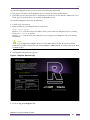
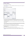
Launching the Ridgeline Client .......................................................................................................................26
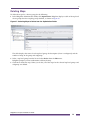
Getting Help ...........................................................................................................................................................29
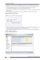
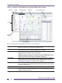
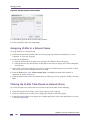
Working with Ridgeline Windows ...........................................................................................................................29
Modifying Table Views ....................................................................................................................................31
Sorting Table Rows..................................................................................................................................31
Resizing Table Columns ..........................................................................................................................31
Moving Table Columns ............................................................................................................................31
Removing Columns From a Table ...........................................................................................................31
Moving Tabbed Windows in Ridgeline ............................................................................................................32
Ridgeline User Roles..............................................................................................................................................32
Ridgeline Concepts and Solutions Guide
1
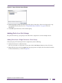
Creating the Device Inventory ................................................................................................................................32
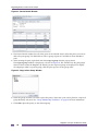
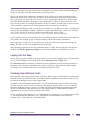
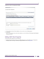
Using Discovery ..............................................................................................................................................33
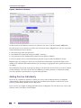
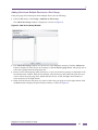
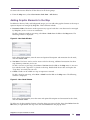
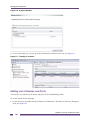
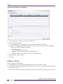
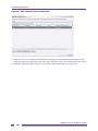
Adding Devices Individually ............................................................................................................................34
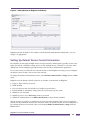
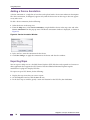
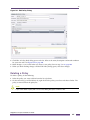
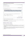
Setting Up Default Device Contact Information...............................................................................................35
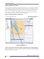
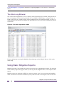
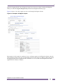
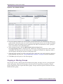
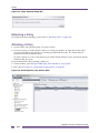
Using Network Views..............................................................................................................................................36
Device Groups and Port Groups .....................................................................................................................38
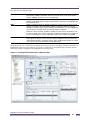
Map Views.......................................................................................................................................................38
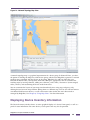
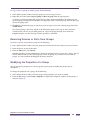
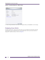
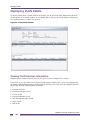
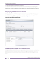
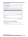
Displaying Device Inventory Information ................................................................................................................39
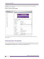
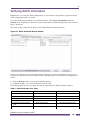
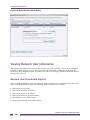
Viewing Device Properties......................................................................................................................................40
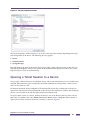
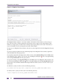
Opening a Telnet Session to a Device ...................................................................................................................41
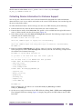
Collecting Device Information for Extreme Support ........................................................................................43
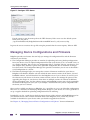
Managing Device Configurations and Firmware.....................................................................................................44
Using the Ridgeline Alarm Manager.......................................................................................................................45
Predefined Alarms...........................................................................................................................................45
The Alarm Log Browser ..................................................................................................................................46
Using Basic Ridgeline Reports ...............................................................................................................................46
Chapter 3: Organizing Devices and Ports Into Groups ........................................................................ 51
About Ridgeline Groups .........................................................................................................................................51
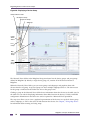
Displaying Groups in the Network Views Folder .............................................................................................51
Group Membership Guidelines .......................................................................................................................53
Managing Device Groups and Port Groups............................................................................................................53
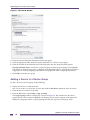
Creating a Group.............................................................................................................................................53
Adding a Device to a Device Group ................................................................................................................54
Adding Ports to a Port Group ..........................................................................................................................55
Adding Ports from a Single Device to a Port Group.................................................................................55
Adding Ports from Multiple Devices to a Port Group................................................................................57
Copying or Moving Groups .............................................................................................................................58
Removing Devices or Ports from Groups........................................................................................................59
Modifying the Properties of a Group ...............................................................................................................59
Displaying Group Details.................................................................................................................................60
Exporting Group Information ...........................................................................................................................61
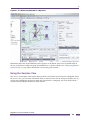
Chapter 4: Using Map Views ................................................................................................................... 63
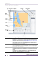
About Network Topology Maps ..............................................................................................................................63
Map Elements .................................................................................................................................................65
Device Nodes ...................................................................................................................................65
Subgroup Nodes...............................................................................................................................66
Hyper Nodes .....................................................................................................................................66
Decorative Nodes .............................................................................................................................66
Text Nodes .......................................................................................................................................66
Clouds...............................................................................................................................................66
Links .................................................................................................................................................66
Navigating Maps .............................................................................................................................................68
Zooming In and Out on a Map .................................................................................................................68
Using the Navigation Box.........................................................................................................................68
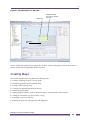
Creating Maps ........................................................................................................................................................69
Creating a Map for a Device Group ................................................................................................................70
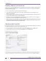
Specifying Map Properties ..............................................................................................................................70
Laying Out the Map .........................................................................................................................................71
Creating User-Defined Links ...........................................................................................................................71
Removing Inactive Links from the Map ...........................................................................................................72
Adding Graphic Elements to the Map .............................................................................................................73
Adding a Device Annotation ............................................................................................................................74
Exporting Maps ...............................................................................................................................................74
Deleting Maps .................................................................................................................................................75
Ridgeline Concepts and Solutions Guide
2
Chapter 5: Provisioning Network Resources ........................................................................................ 77
Provisioning Example .............................................................................................................................................77
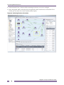
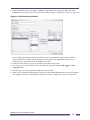
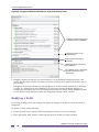
Creating a VLAN .............................................................................................................................................77
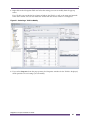
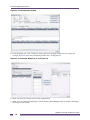
Modifying a VLAN ...........................................................................................................................................80
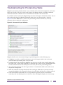
Troubleshooting for Provisioning Tasks .................................................................................................................83
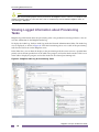
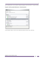
Viewing Logged Information about Provisioning Tasks..........................................................................................84
Chapter 6: Managing Ethernet Services................................................................................................. 87
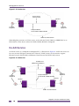
E-Line Service ........................................................................................................................................................87
E-LAN Service ........................................................................................................................................................88
Bandwidth Profiles ..........................................................................................................................................89
Configuring Ethernet Services................................................................................................................................89
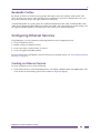
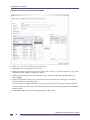
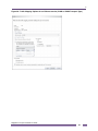
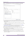
Creating an Ethernet Service ..........................................................................................................................89
Modifying an Ethernet Service ........................................................................................................................94
Creating a Customer Profile ............................................................................................................................95
Creating a Bandwidth Profile...........................................................................................................................96
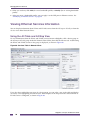
Viewing Ethernet Services Information...................................................................................................................98
Using the All Table and All Map View .............................................................................................................98
Using the Services View .................................................................................................................................99
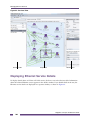
Displaying Ethernet Service Details .....................................................................................................................100
Chapter 7: Importing Services ..............................................................................................................103
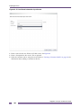
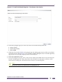
Importing E-Line and E-L AN Services.................................................................................................................103
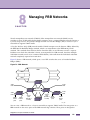
Chapter 8: Managing PBB Networks ....................................................................................................113
SVLANs, BVLANs, CVLANs and ISIDs................................................................................................................114
Configuring BVLANs ............................................................................................................................................114
Creating a BVLAN .........................................................................................................................................115
Modifying a BVLAN .......................................................................................................................................116
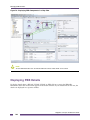
Viewing PBB Information......................................................................................................................................118
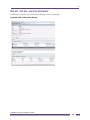
Displaying PBB Details.........................................................................................................................................120
BVLAN, CVLAN, and SVLAN Details............................................................................................................121
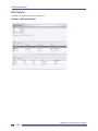
ISID Details ...................................................................................................................................................122
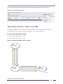
Chapter 9: Managing and Monitoring VPLS Domains ........................................................................123
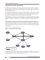
Hierarchical VPLS (H-VPLS) ................................................................................................................................124
VPLS Support in Ridgeline ...................................................................................................................................125
Viewing VPLS Information....................................................................................................................................125
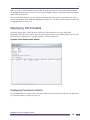
Displaying VPLS Details.......................................................................................................................................127
Displaying Pseudowire Details ......................................................................................................................127
Configuring VPLS .................................................................................................................................................128
Running VPLS Configuration Scripts ............................................................................................................128
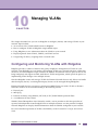
Chapter 10: Managing VLANs ...............................................................................................................131
Configuring and Monitoring VLANs with Ridgeline...............................................................................................131
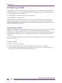
Configuring VLANs ...............................................................................................................................................132
Provisioning VLANs ......................................................................................................................................132
Creating a VLAN ....................................................................................................................................132
Modifying a VLAN ..................................................................................................................................136
Running VLAN Configuration Scripts ............................................................................................................138
Viewing VLAN Information ...................................................................................................................................139
Displaying VLAN Details.......................................................................................................................................140
Viewing VLAN Services Information..............................................................................................................140
Displaying VLAN Details for an Individual Device .........................................................................................141
Ridgeline Concepts and Solutions Guide
3
Displaying VMAN Details ..............................................................................................................................141
Categorizing VLANs With Network Names ..........................................................................................................141
Creating a Network Name .............................................................................................................................141
Assigning VLANs to a Network Name...........................................................................................................142
Filtering the VLANs Table Based on Network Name ....................................................................................142
Chapter 11: Managing Virtual Machines ..............................................................................................145
Overview ..............................................................................................................................................................145
Introduction to the XNV Feature....................................................................................................................145
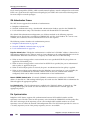
VM Port Configuration............................................................................................................................145
VM Authentication Process ....................................................................................................................146
Ridgeline Authentication .................................................................................................................146
Network (VMMAP) Authentication ..................................................................................................146
Local Authentication .......................................................................................................................146
File Synchronization...............................................................................................................................146
Network Management and Inventory .....................................................................................................147
Example XNV Configuration .........................................................................................................................147
Managing the XNV Feature, VM Tracking............................................................................................................148
Limitations .....................................................................................................................................................148
Identifying VMMs and VMs ...........................................................................................................................149
Virtual Machine Manager Table .............................................................................................................149
Adding and Importing VMs ............................................................................................................................150
Editing VM Manager Settings........................................................................................................................151
Deleting a VM Manager ................................................................................................................................152
Enabling VM Tracking On a Switch...............................................................................................................152
Editing List of Devices and Ports ..................................................................................................................156
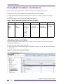
Policy Match Condition Combinations ..................................................................................................................159
Creating a Virtual-Port Profile...............................................................................................................................159
Attaching Policies, VPPs, and VMs ......................................................................................................................161
Attaching a VPP to a VM...............................................................................................................................162
Attaching a Policy to a VPP ..........................................................................................................................165
Detaching VPPs ...................................................................................................................................................167
Detaching a VPP from a VM .........................................................................................................................167
Detaching a VPP from a Policy .....................................................................................................................168
Viewing Information on the VMs Tab....................................................................................................................169
All Table and All Map Views..........................................................................................................................169
Device Group/Subgroup Views .....................................................................................................................171
VM Details View ............................................................................................................................................172
VM Properties view ................................................................................................................................172
NIC Tab..................................................................................................................................................173
History Tab-VM Movement History ........................................................................................................173
Device Details with VM Monitoring................................................................................................................174
VM Monitoring Audit Log ...............................................................................................................................175
Chapter 12: Managing Your EAPS Configuration ...............................................................................177
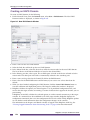
Configuring EAPS ................................................................................................................................................177
Creating an EAPS Domain............................................................................................................................178
Modifying an EAPS Domain ..........................................................................................................................179
Creating a Shared Link ..........................................................................................................................180
Deleting an EAPS Domain ............................................................................................................................180
Viewing EAPS Information ...................................................................................................................................181
The EAPS Map View.....................................................................................................................................182
EAPS Node Icons ..................................................................................................................................182
Link Status .............................................................................................................................................183
Displaying EAPS Domain Details .........................................................................................................................184
Displaying EAPS Details for a Selected Device ............................................................................................184
Ridgeline Concepts and Solutions Guide
4
Verifying EAPS Information ..................................................................................................................................185
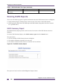
Running EAPS Reports ........................................................................................................................................186
EAPS Summary Report ................................................................................................................................186
EAPS Log Reports ........................................................................................................................................187
Chapter 13: Managing Network Security..............................................................................................189
Security Overview ................................................................................................................................................189
Management Access Security ..............................................................................................................................189
Using RADIUS for Ridgeline User Authentication .........................................................................................190
Configuring a RADIUS Server for Ridgeline User Authentication ..........................................................190
Example: Setting up a VSA to Return Ridgeline Role Information.........................................................191
Example: Setting the Service Type for a Built-in Ridgeline Role ...........................................................192
Securing Management Traffic .......................................................................................................................192
Using SNMPv3 for Secure Management ...............................................................................................192
Using SSHv2 to Access Network Devices. ............................................................................................193
Securing Ridgeline Client-Server Traffic .......................................................................................................194
Monitoring Switch Configuration Changes ...........................................................................................................195
Using the MAC Address Finder ............................................................................................................................196
Using Alarms to Monitor Potential Security Issues...............................................................................................196
Device Syslog History...........................................................................................................................................197
Network Access Security with VLANs ..................................................................................................................198
Chapter 14: Policies ...............................................................................................................................201
Overview ..............................................................................................................................................................201
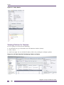
Viewing Policies for Devices .........................................................................................................................202
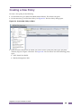
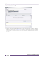
Creating a New Policy ..........................................................................................................................................203
Copying a Policy to Create a New Policy ......................................................................................................209
Editing a Policy..............................................................................................................................................210
Deleting a Policy ...........................................................................................................................................211
Detaching a Policy ........................................................................................................................................212
Attaching a Policy..........................................................................................................................................212
Categorizing Policies ............................................................................................................................................213
Categorizing Policy Rules .............................................................................................................................214
Creating and Managing Roles ..............................................................................................................................214
Viewing Active Policies for Devices...............................................................................................................214
Chapter 15: Tuning and Debugging Ridgeline ....................................................................................215
Monitoring and Tuning Ridgeline Performance ....................................................................................................215
Disabling Ridgeline Management for a Device ......................................................................................215
Polling Types and Frequencies .....................................................................................................................216
SNMP Polling .........................................................................................................................................216
MAC Address Polling .............................................................................................................................216
Telnet Polling .........................................................................................................................................217
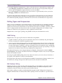
Performance of the Ridgeline Server ............................................................................................................217
Tuning the Alarm System .....................................................................................................................................217
Disabling Unnecessary Alarms .....................................................................................................................218
Limiting the Scope of Alarms ........................................................................................................................219
Using Device Groups and Port Groups for Alarm Scopes .....................................................................221
The Alarm and Event Log Archives...............................................................................................................221
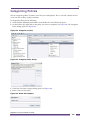
Using the MIB Poller Tools ...................................................................................................................................221
Defining a MIB Collection ..............................................................................................................................222
The MIB Poller Summary ..............................................................................................................................223
Loading, Starting and Stopping a Collection ..........................................................................................224
The MIB Collection Detail Report...........................................................................................................224
The MIB Poller Detail Report .................................................................................................................225
Viewing the XML Collection Definition ...................................................................................................226
Ridgeline Concepts and Solutions Guide
5
Exporting the Collected Data .................................................................................................................226
The MIB Query Tool ......................................................................................................................................226
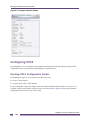
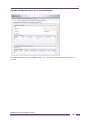
Reconfiguring Ridgeline Ports ..............................................................................................................................227
Using the Ridgeline Debugging Tools ..................................................................................................................228
Reconfiguring the FreeRadius Server ..................................................................................................................228
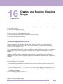
Chapter 16: Creating and Running Ridgeline Scripts.........................................................................229
About Ridgeline Scripts ........................................................................................................................................229
Bundled Ridgeline Scripts .............................................................................................................................230
The Ridgeline Script Interface ..............................................................................................................................230
Managing Ridgeline Scripts..................................................................................................................................232
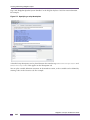
Creating a New Ridgeline Script ...................................................................................................................233
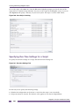
Specifying Run-Time Settings for a Script.....................................................................................................236
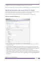
Specifying Permissions and Launch Points for a Script ................................................................................237
Running a Script............................................................................................................................................238
Importing Scripts into Ridgeline ....................................................................................................................242
Categorizing Scripts ......................................................................................................................................243
Specifying an Ridgeline Script as an Alarm Action .......................................................................................244
Configuring Script Tasks ...............................................................................................................................244
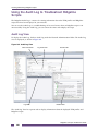
Using the Audit Log to Troubleshoot Ridgeline Scripts ........................................................................................246
Audit Log View ..............................................................................................................................................246
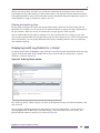
Filtering the Audit Log View ...................................................................................................................247
Displaying Audit Log Details for a Script .......................................................................................................247
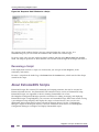
Rerunning a Script ........................................................................................................................................248
About ExtremeXOS Scripts ..................................................................................................................................248
Chapter 17: Using Identity Management ..............................................................................................249
Identity Management Software License ...............................................................................................................249
Overview ..............................................................................................................................................................249
Role-Based Access Control..................................................................................................................................250
Roles, Policies, and Rules ............................................................................................................................250
Roles ......................................................................................................................................................250
Policies...................................................................................................................................................251
Role Hierarchy ..............................................................................................................................................251
Role Inheritance ............................................................................................................................................253
LDAP Attributes and Server Selection ..........................................................................................................254
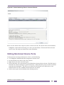
Enabling Monitoring on Switches and Ports .........................................................................................................254
Editing Monitored Device Ports ............................................................................................................................259
Disabling Monitoring......................................................................................................................................260
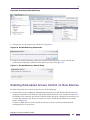
Enabling Role-based Access Control on New Devices ........................................................................................261
Disabling Role-based Access Control ...........................................................................................................265
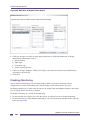
Creating Roles......................................................................................................................................................265
Defining a New Role .....................................................................................................................................266
Creating a Child Role with Conditions Inherited from Its Parent ............................................................268
Creating a Child Role with Conditions Inherited from a Different Role ..................................................271
Viewing Roles ...............................................................................................................................................272
Viewing Role Details ..............................................................................................................................273
Editing Roles .................................................................................................................................................274
Deleting Roles ...............................................................................................................................................275
Policy Match Condition Combinations ..................................................................................................................276
Attaching Policies to Roles............................................................................................................................276
Deleting a Policy Attached to a Role .............................................................................................................278
Error and Results Handling ...........................................................................................................................279
Configuring Directory Servers ..............................................................................................................................279
Viewing the Server Directory.........................................................................................................................280
Managing Global Directory Servers ..............................................................................................................280
Ridgeline Concepts and Solutions Guide
6
Configuring a New Directory Server..............................................................................................................280
Editing LDAP Client Properties .....................................................................................................................283
Deleting a Directory Server ...........................................................................................................................285
Viewing Network User Information .......................................................................................................................286
Network User Dashboard Reports ................................................................................................................286
Users Table ...................................................................................................................................................287
Active Users Tab....................................................................................................................................288
Inactive and Active Users Tab ...............................................................................................................289
Displaying Network User Details ..........................................................................................................................290
Displaying Identity Management Reports.............................................................................................................292
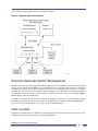
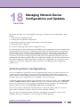
Chapter 18: Managing Network Device Configurations and Updates ...............................................293
Archiving Device Configurations...........................................................................................................................293
Baseline Configurations .......................................................................................................................................294
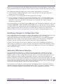
Identifying Changes in Configuration Files....................................................................................................295
Automatic Differences Detection ...................................................................................................................295
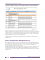
Device Configuration Management Log ...............................................................................................................296
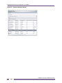
Managing Firmware Upgrades .............................................................................................................................297
Automated Retrieval of Firmware Updates from Extreme.............................................................................297
Detection of Firmware Obsolescence for Network Components...................................................................297
Appendix A: Troubleshooting ...............................................................................................................299
Troubleshooting Aids............................................................................................................................................299
About Ridgeline Window ...............................................................................................................................299
Enabling the Java Console ...........................................................................................................................300
Ridgeline Client Issues .........................................................................................................................................300
Ridgeline Database ..............................................................................................................................................301
Ridgeline Server Issues .......................................................................................................................................302
VLAN Management ..............................................................................................................................................305
Alarm System .......................................................................................................................................................305
Ridgeline Inventory...............................................................................................................................................307
Printing .................................................................................................................................................................307
Reports .................................................................................................................................................................308
Configuration Manager .........................................................................................................................................308
Appendix B: Configuring Devices for Use With Ridgeline .................................................................309
Configuring Ridgeline as a Syslog Receiver ........................................................................................................309
Setting Ridgeline as a Trap Receiver ...................................................................................................................310
The Ridgeline Third-party Device Integration Framework ....................................................................................310
Ridgeline Inventory Integration .....................................................................................................................311
The Abstract Type Library XML file........................................................................................................311
The OID folder .......................................................................................................................................314
The dpsimages.zip File ..........................................................................................................................314
Telnet Integration ..........................................................................................................................................315
Alarm Integration ...........................................................................................................................................316
Editing the Events.xml file ......................................................................................................................316
Adding the MIB(s) to Ridgeline ..............................................................................................................317
Launching Third Party Applications...............................................................................................................317
Appendix C: Using SSH for Secure Communication ..........................................................................319
Overview of Tunneling Setup ...............................................................................................................................319
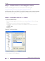
Step 1: Install PuTTY on the Ridgeline Client ......................................................................................................320
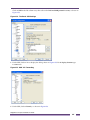
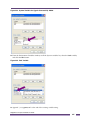
Step 2: Configure the PuTTY Client .....................................................................................................................320
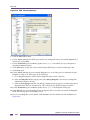
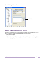
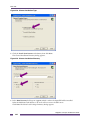
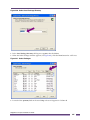
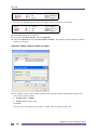
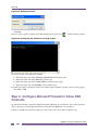
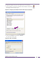
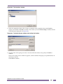
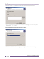
Step 3: Installing OpenSSH Server ......................................................................................................................323
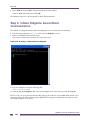
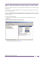
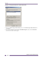
Step 4: Configure Microsoft Firewall to Allow SSH Connects ..............................................................................328
Step 5: Initiate Ridgeline Server/Client Communication.......................................................................................330
Ridgeline Concepts and Solutions Guide
7
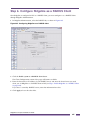
Appendix D: Configuring RADIUS for Ridgeline Authentication .......................................................331
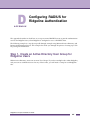
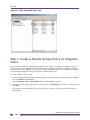
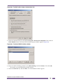
Step 1. Create an Active Directory User Group for Ridgeline Users ....................................................................331
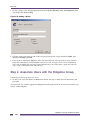
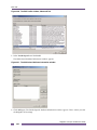
Step 2. Associate Users with the Ridgeline Group...............................................................................................332
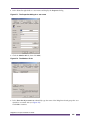
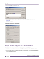
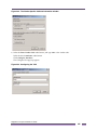
Step 3. Enable Ridgeline as a RADIUS Client .....................................................................................................334
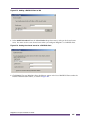
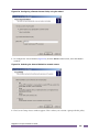
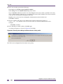
Step 4. Create a Remote Access Policy for Ridgeline Users ...............................................................................336
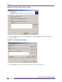
Step 5. Edit the Remote Access Policy to add a VSA ..........................................................................................341
Step 6. Configure Ridgeline as a RADIUS Client .................................................................................................347
Appendix E: Ridgeline Utilities .............................................................................................................349
Package Debug Info Utility ...................................................................................................................................349
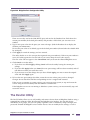
Port Configuration Utility.......................................................................................................................................350
The DevCLI Utility ................................................................................................................................................351
Using the DevCLI Commands.......................................................................................................................352
DevCLI Examples .........................................................................................................................................353
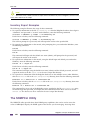
Inventory Export Scripts .......................................................................................................................................354
Using the Inventory Export Scripts ................................................................................................................354
Inventory Export Examples ...........................................................................................................................356
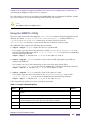
The SNMPCLI Utility.............................................................................................................................................356
Using the SNMPCLI Utility ............................................................................................................................357
SNMPCLI Examples .....................................................................................................................................358
The AlarmMgr Utility .............................................................................................................................................358
Using the AlarmMgr Command .....................................................................................................................358
AlarmMgr Output ...........................................................................................................................................360
AlarmMgr Examples ......................................................................................................................................360
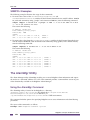
The FindAddr Utility ..............................................................................................................................................361
Using the FindAddr Command ......................................................................................................................361
FindAddr Output ............................................................................................................................................363
FindAddr Examples .......................................................................................................................................363
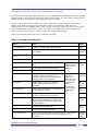
The TransferMgr Utility .........................................................................................................................................363
Using the TransferMgr Command .................................................................................................................364
TransferMgr Examples ..................................................................................................................................366
The ImportResources Utility .................................................................................................................................366
Using the ImportResources Command .........................................................................................................366
Importing from a File .......................................................................................................................367
Importing from an LDAP Directory ..................................................................................................367
Importing from an Windows Domain Controller or NIS Server .......................................................367
ImportResources Examples ..........................................................................................................................368
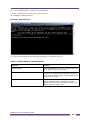
FreeRadius Server Configuration Commands......................................................................................................368
Ridgeline Concepts and Solutions Guide
8
Preface
This preface provides an overview of this guide, describes guide conventions, and lists other useful
publications.
Introduction
This guide provides the required information to use the Ridgeline software. It is intended for use by
network managers who are responsible for monitoring and managing Local Area Networks, and
assumes a basic working knowledge of:
●
Local Area Networks (LANs)
●
Ethernet concepts
●
Ethernet switching and bridging concepts
●
Routing concepts
●
The Simple Network Management Protocol (SNMP)
NOTE
If the information in the Release Notes shipped with your software differs from the information in this
guide, follow the Release Note.
Terminology
When features, functionality, or operation is specific to the Summit, Alpine, or BlackDiamond switch
family, the family name is used. Explanations about features and operations that are the same across all
Extreme switch product families simply refer to the product as the “Extreme device” or “Extreme
switch.” Explanations about features that are the same for all devices managed by Ridgeline (both
Extreme devices and others) are simply refer to “devices.”
Ridgeline Concepts and Solutions Guide
9
Conventions
Conventions
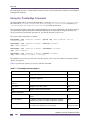
Table 1 and Table 2 list conventions that are used throughout this guide.
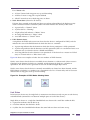
Table 1: Notice Icons
Icon
Notice Type
Alerts you to...
Note
Important features or instructions.
Caution
Risk of unintended consequences or loss of data.
Warning
Risk of permanent loss of data.
.
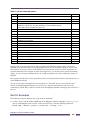
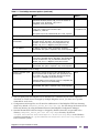
Table 2: Text Conventions
Convention
Description
Screen displays
This typeface represents information as it appears on the screen.
Screen displays bold
This typeface indicates how you would type a particular command.
The words “enter”
and “type”
When you see the word “enter” in this guide, you must type something, and then
press the Return or Enter key. Do not press the Return or Enter key when an
instruction simply says “type.”
[Key] names
Key names appear in text in one of two ways. They may be
•
referred to by their labels, such as “the Return key” or “the Escape key.”
•
written with brackets, such as [Return] or [Esc].
If you must press two or more keys simultaneously, the key names are linked with a
plus sign (+). For example:
Press [Ctrl]+[Alt]+[Del].
Words in bold type
Bold text indicates a button or field name.
Words in italicized type
Italics emphasize a point or denote new terms at the place where they are defined in
the text.
Ridgeline Concepts and Solutions Guide
10
Related Publications
The Ridgeline documentation set includes the following:
●
Ridgeline Reference Guide
●
Ridgeline Concepts and Solutions Guide (this guide)
●
Ridgeline Installation and Upgrade Guide
●
Ridgeline Release Notes
●
Ridgeline License Agreement
Both the Ridgeline Reference Guide and the Ridgeline Concepts and Solutions Guide can be found online in
Adobe Acrobat PDF format in the docs subdirectory of the Ridgeline installation directory.
You must have Adobe Acrobat Reader version 5.0 or later (available from http://www.adobe.com free of
charge) to view these manuals.
The Ridgeline software also includes context-sensitive online Help, available from the Help menu in
each Ridgeline window.
Other manuals that you will find useful are:
●
ExtremeWare Software User Guide
●
ExtremeWare Command Reference Guide
●
ExtremeXOS Concepts Guide
●
ExtremeXOS Command Reference Guide
For documentation on Extreme Networks products, and for general information about Extreme
Networks, see the Extreme Networks home page:
●
http://www.extremenetworks.com
Customers with a support contract can access the Technical Support pages at:
●
http://www.extremenetworks.com/services/eSupport.asp
The technical support pages provide the latest information on Extreme Networks software products,
including the latest Release Notes, information on known problems, downloadable updates or
patches as appropriate, and other useful information and resources.
Customers without contracts can access manuals at:
●
http://www.extremenetworks.com/services/documentation/
Ridgeline Concepts and Solutions Guide
11
Related Publications
Ridgeline Concepts and Solutions Guide
12
1
Ridgeline Overview
CHAPTER
This chapter describes:
●
The features of the Ridgeline™ software
●
The Ridgeline software architecture and components
●
Overview of Ridgeline switch management
Introduction
Today's corporate networks commonly encompass hundreds or thousands of systems, including
individual end user systems, servers, network devices such as printers, and internetworking systems.
Extreme Networks™ recognizes that network managers have different needs, and delivers a suite of
management tools to meet those needs.
The Ridgeline (Ridgeline) Management Suite is a scalable full-featured network management tool that
simplifies configuration, troubleshooting, and status monitoring of IP-based networks. Offering a
comprehensive set of network management applications providing the ability to configure, monitor,
troubleshoot, and manage the network and its elements, Ridgeline delivers on both the basic
requirements of network management while adding valuable and intuitive features that help save time
by streamlining common tasks.
Ridgeline offers a comprehensive set of network management applications that are easy to use from a
workstation configured with a web browser and the Java plug-in. The Ridgeline application and
database support three of the most popular operating environments in the marketplace, Microsoft
Windows, Red Hat Enterprise Linux, and Sun Microsystems’ Solaris.
Ridgeline Features
In large corporate networks, network managers need to manage systems “end to end.”
Ridgeline is a powerful, flexible and easy-to-use application for centralizing configuration,
troubleshooting, and status monitoring of IP-based networks of Extreme Networks switches and
selected third-party devices, regardless of the network size.
Ridgeline establishes a new benchmark for accommodating convergence applications by offering
intuitive user interfaces and by reducing the complexity of managing converged networking
Ridgeline Concepts and Solutions Guide
13
Ridgeline Overview
environments. Ridgeline’s open architecture accommodates a multi-vendor, service-rich environment
that enables voice-class availability and the enforcement of robust security policies.
●
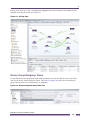
Operational Simplicity. Simplicity begins with a detailed real-time view of the entire network.
Ridgeline’s maps provide users with an overview of every element of the network and how they all
connect at Layer 2 and Layer 3. Centralized configuration management and firmware management
simplifies the configuration and maintenance of your network elements. These functions can be
performed simultaneously on groups of devices anywhere on the network as well as on devices
individually.
●
Voice-Class Availability. Ridgeline’s availability is greatly enhanced by granular health and status
monitoring of the network. Ethernet Automatic Protection Switching (EAPS) protocol support within
Ridgeline enhances a highly available Extreme Networks switching environment. The Real Time
Statistics feature provides a graphical representation of utilization and error statistics for multiple
ports on a device, device slot, or within a port group.
●
Point-and-click network provisioning. Ridgeline’s provisioning features simplify network
configuration tasks with selectable options in dialog boxes. Ridgeline automatically validates the
options you’ve selected prior to deploying the configuration to managed devices, ensuring that the
configuration is correct before it goes into production.
●
Comprehensive Security. Ridgeline provides multiple features that control and monitor the security
features on Extreme Networks’ products, including creation and management of VLANs easily
throughout the network. The IP/MAC Address Finder tool can locate any MAC address on your
network.
●
Hierarchical grouping for devices and ports. Ridgeline allows you to assemble the devices and
ports in your network into groups and subgroups, and view information about them or manage
them at a group level. You can organize your network into a hierarchy of groups, with subgroups
for campuses, buildings, and individual rooms.
●
Integrated network topology maps. Ridgeline’s network topology map feature is integrated with the
device group functionality, so that when you create a device group, you have the option of selecting
the Map view of the group, which causes Ridgeline to generate a network topology map, populated
with the devices in the group. Ridgeline automatically adds any links that exist between the device
nodes, and organizes them into submaps as appropriate. You can further customize your maps with
background images, decorative nodes and clouds, and user-specified links.
●
Overlay views of VLANs in network maps. Information about the VLANs configured on the
devices in your network is readily accessible from Network View windows. VLAN services
information (VMAN, VLAN aggregation, VLAN translation, and Private VLAN) is incorporated into
network topology maps.
●
Advanced scripting capabilities. Ridgeline includes an interface for creating and executing scripts
on your managed devices. Scripts created in Ridgeline can include ExtremeXOS CLI commands, as
well as commands and constructs in the Tcl scripting language. Scripts bundled with Ridgeline ease
common network configuration tasks. Ridgeline scripts can also be configured as script tasks, which
can run automatically at designated times.
●
Multi-platform capability. The Ridgeline server supports Sun SPARC and Intel platforms, and the
Microsoft Windows, Red Hat Enterprise Linux and Solaris operating environments. Clients on any of
these platforms can connect to servers on any platform.
●
Support for multiple users with security. Users must log in to the Ridgeline application, and can be
granted different levels of access to the application features based on their assigned role. Three basic
predefined roles are provided, and additional user roles can be created. Telnet and SSH access to
Extreme switches can also be controlled based on the user identity. To protect sensitive data from
being intercepted or altered by unauthorized access, Secure Shell 2 (SSHv2) protocol and HTTPS
protocols are provided. These protocols encrypt traffic between the switch management port and the
Ridgeline.
Ridgeline Concepts and Solutions Guide
14
1
●
Support for third-party devices. Any device running a MIB-2 compatible SNMP agent can be
discovered by Ridgeline and monitored at a basic level. These devices can appear on a topology
map, with basic status and alarm handling based on MIB-2 functionality. Based on Ridgeline’s Third
Party Integration Framework, selected appliances from Extreme Networks partners can be integrated
into Ridgeline in a robust fashion that allows reporting, alarm management, and monitoring with
graphical front and back panel views.
Ridgeline Concepts and Solutions Guide
15
Ridgeline Overview
●
Manage large numbers of devices. Ridgeline server can manage up to 2000 devices with a single
installation of the Ridgeline software. For even larger networks, you can split the management task
among several Ridgeline servers in a distributed server mode that lets you monitor the status of
those servers from a single client.
●
VPLS discovery and visualization. Ridgeline can discover the Virtual Private LAN Service (VPLS)
configuration on the managed devices in your network, and display an overlay view of selected
VPLS instances, including information about specific pseudo wires. Ridgeline scripts can create
VPLS instances and configure devices as VPLS peers.
●
PBB discovery, visualization, and provisioning. Ridgeline identifies the Service VLANs (SVLANs),
Backbone VLANs (BVLANs), Customer VLANs (CVLANs), and Extended Service ID (ISID)
instances in your Provider Backbone Bridge (PBB) networks. You can display an overlay view of a
selected PBB network, along with detailed information about PBB components in Ridgeline tables.
Ridgeline’s PBB provisioning feature allows you to create BVLANs on selected devices, ports, or
links, as well as modify and delete existing BVLANs.
●
Ethernet service provisioning. Using the service provisioning wizard, you can create E-Line (pointto-point) and E-LAN (multipoint-to-multipoint) services. You can select the devices and ports that
make up the service, specify the transport method (VLAN, VMAN, or PBB), create and apply
bandwidth profiles, then validate the configuration and deploy it on your network.
The Ridgeline features are described in more detail in the following sections. The rest of this manual
describes how to best use these features to manage various aspects of your network. For detailed
instructions on using specific features of Ridgeline see the context-sensitive online Help available from
the Help menu at the top of Ridgeline windows. The Ridgeline Reference Guide also provides a detailed
description of the functionality of each Ridgeline feature.
Inventory Management
Ridgeline keeps a database of all devices managed by the software. Any Ridgeline user with read-only
access to this feature can view status information about the switches currently known to Ridgeline.
Ridgeline provides a discovery function to discover the components of your network. Users with the
appropriate access (roles with read/write access) can use this feature to discover Extreme devices as
well as any third-party devices running a MIB-2 compatible SNMP agent. Devices may be discovered
by specific IP address or within a range of IP addresses. Third-party devices that support SNMP version
3 (SNMPv3) are discovered as SNMP version 1 (SNMPv1) and are added to the Ridgeline database as
SNMPv1 devices. Network devices can also be added to the Ridgeline database manually.
Once a network device is known to the Ridgeline database, you can copy it to a specific device group,
and configure it using a Device Manager (ExtremeWare Vista for Extreme devices). Ridgeline also
allows you to set a device to unmanaged status so that Ridgeline will not poll and can ignore traps
when a device is scheduled for maintenance.
Ridgeline also provides a command-line utility that lets you create device groups and import large
numbers of devices into the database through scripts, to streamline the process of adding and
organizing devices for management purposes. These utilities are described in Appendix E “Ridgeline
Utilities”.
Ridgeline displays detailed information about individual devices through a front panel image that
provides a visual device representation, with associated detailed configuration and status information.
Any Ridgeline user can view status information about the network devices known to Ridgeline. Users
with the appropriate access permissions can also view and modify configuration information for those
switches.
Ridgeline Concepts and Solutions Guide
16
1
Network Views
Ridgeline’s Network Views provide at-a-glance information about the devices, device groups, and port
groups in your network. You can display summary information about the devices or ports, links
between devices, VLANs, and EAPS domains, and you can select individual devices in tables or maps
to view detailed information about them.
Device Groups and Port Groups
Ridgeline has a powerful grouping feature that allows you to assemble groups of devices and ports, and
view information about them or manage them at a group level. You can organize your devices and
ports in a logical group structure, and administer and view status of components within the individual
groups. Graphical representations of device groups can appear in Network Views
Map Views
Ridgeline’s maps allow you to view Ridgeline-managed devices and the links between devices
graphically, as a set of maps. These maps can be organized into sets of submaps that allow you to
represent your network as a hierarchical system of campuses, buildings, floors, closets, or whatever
logical groupings you want.
A Ridgeline map is a graphical representation of a device group. When you create a device group, you
have the option of selecting the Map view of the group, which causes Ridgeline to generate a network
topology map, populated with the devices in the group.
Ridgeline also adds any links that exist between the device nodes. You can customize the resulting
maps by moving elements, adding new elements, such as links, “decorative” (non-managed) nodes, and
text, and customizing the device nodes themselves. Information about the links and devices in maps is
displayed graphically, with colored icons indicating device alarm level and state of the links between
devices.
Ridgeline Scripts
Ridgeline scripts are files containing CLI commands, control structures, and data manipulation
functions that can be executed on managed devices. Ridgeline scripts support syntax and constructs
from ExtremeXOS 12.1 (and higher) CLI scripts and the Tcl scripting language. Ridgeline includes a
number of bundled scripts that can perform such tasks as downloading firmware, uploading/
downloading configuration files, and configuring VLANs.
Ridgeline scripts can be run manually from the Ridgeline client, or you can configure them as script
tasks, which can run automatically at designated times.
The Alarm Manager
The Ridgeline Alarm System provides fault detection and alarm handling for the network devices
monitored by the Ridgeline software. This includes Extreme devices and some third-party devices—
those that the Ridgeline software can include in its database. The Alarm Manager also lets you define
your own alarms that will report errors under conditions you specify, such as repeated occurrences or
exceeding threshold values. You can specify the actions that should be taken when an alarm occurs, and
you can enable and disable individual alarms.
Ridgeline Concepts and Solutions Guide
17
Ridgeline Overview
Fault detection is based on SNMP traps, RMON traps, Syslog messages, and some limited polling. The
Alarm Manager supports SNMP MIB-2 and the Extreme Networks private MIB. You can also configure
alarms based on certain event thresholds, or on the content of Syslog messages. When an alarm occurs
you can specify actions such as sending e-mail, forwarding a trap, running a program, running a script,
sending a page, or sounding an audible alert.
The Configuration Manager and the Firmware Manager
The Ridgeline Configuration Manager provides a mechanism and a graphical interface for uploading
and downloading configuration files to and from managed devices. The Ridgeline Firmware Manager
can download ExtremeWare software images and BootROM images to Extreme Networks devices, or to
Extreme modules that include software.
The Configuration Manager provides a framework for storing the configuration files, to allow tracking
of multiple versions. Configuration file uploads can be performed on demand, or can be scheduled to
occur at regular times—once a day, once a week, or at whatever interval is appropriate.
The Configuration Manager also includes a facility to create and edit ExtremeXOS scripts, then deploy
them to managed devices.
The Firmware Manger can be configured to automatically track the firmware versions in Extreme
devices, will indicate whether newer versions are available, and can automatically retrieve those
versions from Extreme if desired.
The IP/MAC Address Finder
The IP/MAC Address Finder lets you search for specific network addresses (MAC or IP addresses) and
identify the Extreme Networks switch and port on which the address resides. You can also use the IP/
MAC Finder to find all addresses on a specific port or set of ports. If you have enabled Ridgeline’s
periodic MAC Address polling, which does polls for edge port address information, you can perform a
fast address search by just searching the Ridgeline database for this information. Alternatively you can
direct Ridgeline to search the FDBs of specific Extreme switches. You can export the results of your
search to a file, either on the server or on your local (client) system.
Real-Time Statistics
The Statistics feature of the Ridgeline software provides a graphical presentation of utilization and error
statistics for Extreme switches in real time. The data is taken from Management Information Base (MIB)
objects in the etherHistory table of the Remote Monitoring (RMON) MIB. You can choose from a variety
of styles of charts and graphs as well as a tabular display.
You can view data for multiple ports on a device, device slot, or within a port group, optionally
limiting the display to the “top N” ports (where N is a number you can configure). You can also view
limited historical statistics for an individual port. If you choose to view a single port, the display shows
the value of the selected variable(s) over time, and can show utilization history, total errors history, or a
breakdown of individual errors.
In addition, the Statistics feature lets you “snapshot” a graph or table as a separate browser page. You
can then save, print, or e-mail the page.
Ridgeline Concepts and Solutions Guide
18
1
Ridgeline Reports
Ridgeline Reports are HTML pages that can be accessed separately from the main Ridgeline user
interface, without logging on to Ridgeline. Ridgeline reports do not require Java, so reports can be
loaded quickly, even over a dial-up connection, and can be viewed on systems that cannot run the
Ridgeline client. Reports can be printed using your browser’s Print function.
The Reports capability provides a large number of predefined HTML reports that present a variety of
types of information from the Ridgeline database. You can also create your own reports by writing Tcl
scripts. Further, within the Reports Module are several useful tools such as a MIB Browser and other
tools that can provide Ridgeline system information.
Reports can also be accessed from within Ridgeline. A Summary report is displayed on the Ridgeline
Home page, which provides basic information on the status of Ridgeline devices and alarms. From this
report you can access other more detailed reports.
Role-based Access Management
All Ridgeline users must log on with a user name and password in order to access Ridgeline features.
Ridgeline initially provides four user roles:
●
Monitor role: users who can view status information only.
●
Manager role: users who can modify device parameters as well as view status information.
●
Administrator role: users who can create, modify and delete Ridgeline user accounts as well as
perform all the functions of a user with Manager access.
●
Disabled role: users whose account information is maintained, but who have no access to any
features of the product.
An Administrator user can create additional roles, can modify the capabilities available under each role,
and can add and delete Ridgeline users, as well as enable or disable access for individual users.
By default, Ridgeline provides its own authentication and authorization for Ridgeline users. However,
through Ridgeline Administration, Ridgeline can be configured to act as a Remote Authentication Dial
In User Service (RADIUS) client, allowing it to use an external RADIUS server to authenticate Ridgeline
users. As an option, the external RADIUS server can be configured to return user role information as
well as the user authentication.
As an alternative, Ridgeline can be configured to act as a RADIUS server, providing authentication for
Ridgeline users as well as for other devices such as Extreme switches. However, the RADIUS server
built into Ridgeline should only be used for demonstration or testing purposes, and should not be used
to provide primary authentication services in a production environment. The Ridgeline RADIUS server
is not sufficiently robust to perform as the authentication server in a production environment.
Distributed Server Mode
To manage very large numbers of network devices, or devices that are geographically distributed, the
management task can be divided up between multiple Ridgeline servers. Each server in the server
group is updated at regular intervals with network summary and status information from the other
servers in the group. From the Ridgeline home page, a client attached to any one of the servers in the
server group can view summary status information from the other servers in the group in addition to
the standard Network Summary report. The Ridgeline client also lets the user easily navigate between
the different servers in the group to see detailed management information about the devices managed
by those servers.
Ridgeline Concepts and Solutions Guide
19
Ridgeline Overview
EAPS Monitoring and Configuration Verification
Ethernet Automatic Protection Switching (EAPS) provides “carrier-class” network resiliency and
availability for enterprise networks. Ridgeline monitors EAPS rings from Network Views. You can
identify and display the status of EAPS rings, including Master and Transit nodes, link status, and a
variety of status information. Detailed status information is provided in multiple tables for domains,
devices and links.
You can also run a configuration verification which produces a report that details any configuration
errors detected among your EAPS nodes or domains.
Ridgeline Software Architecture
The Ridgeline software is made up of three major functional components:
●
The Ridgeline Server. The server is responsible for managing security and communicating with the
managed objects, database, and client systems.
●
The Ridgeline Database. The database is a Relational Database Management System (RDBMS),
which is used as both a persistent data store and a data cache.
●
The Ridgeline Client. The client is a Java application downloaded on demand from the server to a
workstation running a supported browser and the Java plug-in. To start the client, a user points his
or her browser to the Ridgeline server and clicks the Log on to Ridgeline link. The client application
is then automatically downloaded to the user’s workstation and started.
Ridgeline Concepts and Solutions Guide
20
1
Figure 1 illustrates the architecture of the Ridgeline software.
Figure 1: Ridgeline Software Architecture
Extreme Networks Switch Management
Ridgeline primarily uses the Simple Network Management Protocol (SNMP) to monitor and manage the
devices in the network. The Ridgeline server periodically does a status poll of the devices it is managing
to determine if the devices are still accessible. It also does a full detailed poll of each device at longer
intervals. This interval for this less frequent detailed polling can be adjusted on each individual device.
The Ridgeline software also gives you the ability to gather device status at any time using the Update
devices option under the View menu.
To avoid the overhead of frequent device polling, the Ridgeline software also uses a mechanism called
SmartTraps to identify changes in Extreme device configuration. In addition, standard SNMP MIB-2
traps can be used to define alarms for a large variety of other conditions.
SNMP and MIBs
Ridgeline uses SNMP whenever possible to obtain information about the devices it is managing, and to
implement the configuration changes made through Ridgeline.
Ridgeline Concepts and Solutions Guide
21
Ridgeline Overview
The Remote Monitoring (RMON) MIB
Ridgeline can use statistics gathered from the Remote Monitoring (RMON) MIB to provide utilization
statistics on a port-by-port basis, if RMON is supported and enabled on the Extreme devices Ridgeline
is managing. Utilization and error statistics can be displayed within the Real-Time Statistics application,
which provides a number of chart, graph, and tabular display formats. The Ridgeline Alarm Manager
also provides the ability to define threshold-based RMON rules for generating trap events that can be
used in Ridgeline alarm definitions.
Traps and Smart Traps
Fault detection is based on Simple Network Management Protocol (SNMP) traps, syslog messages, and
some limited polling. The Alarm System supports SNMP Management Information Base-2 (MIB-2), the
Extreme Networks private MIB, Remote Monitoring (RMON) traps, and selected traps from other MIBs.
The Ridgeline software uses a mechanism called SmartTraps to identify changes in Extreme device
configuration.
When an Extreme switch is added to the Ridgeline database, the Ridgeline software creates a set of
SmartTraps rules that define the configuration change events that the Ridgeline server needs to know
about. These rules are downloaded into the Extreme switch, and the Ridgeline server is automatically
registered as a trap receiver on the switch. Subsequently, whenever a status or configuration change
takes place, the ExtremeWare software on the switch uses the SmartTraps rules to determine if the
Ridgeline server should be notified. These changes can be changes in device status, such as fan failure
or overheating, or configuration changes made on the switch through the ExtremeWare CLI or
ExtremeWare Vista.
For non-Extreme devices, Ridgeline does not automatically register itself as a trap receiver; you must
manually configure those devices to send traps to Ridgeline. See “Configuring Devices for Use With
Ridgeline” on page 309 for information on configuring devices to send traps to Ridgeline.
Device Status Polling
Ridgeline uses several types of polling to monitor the status of the devices it manages. Since device
polling adds a certain amount of traffic load to the network, Ridgeline tries to minimize the amount of
polling that it does, and many aspects of its polling algorithms are configurable.
Ridgeline polls for basic device status approximately every five minutes using SNMP. This poll interval
can be changed in Ridgeline Administration under the Server Properties for SNMP. Ridgeline also polls
periodically for detailed device status information. By default, this interval is 30 minutes for Extreme
modular chassis switches, and 90 minutes for Extreme stackable chassis switches. The detailed polling
interval can be set for individual devices. The detailed polling gets more complete information, still
only polls for information that has changed; a manual Update Devices action is required to retrieve all
information about the device. An Update Devices action is performed automatically whenever the
Ridgeline client application is started.
Telnet Polling
When it is not possible to use SNMP to obtain information from Extreme devices, Ridgeline uses Telnet
polling instead. Ridgeline uses Telnet polling to obtain MAC address information for edge ports from a
device Forwarding Database (FDB) and to obtain netlogin information. Telnet polling is also used to
obtain power supply IDs for Alpine devices.
Ridgeline Concepts and Solutions Guide
22
1
Optionally, you can use SSH2 instead of Telnet to communicate with Extreme Networks devices. This
requires that you run a version of ExtremeWare or ExtremeXOS that supports SSH.
You can disable Telnet polling if necessary through the Server Properties for Devices in Ridgeline
Administration. However, you will lose the ability to collect edge port information via FDB polling, as
well as netlogin information.
Edge Port Polling Using the MAC Address Poller
Ridgeline can maintain information about the MAC and IP addresses detected on Extreme switch edge
ports by polling the FDB tables of the Extreme switches it is managing. If MAC address polling is
enabled, Ridgeline uses Telnet polling to retrieve FDB information at regular intervals based on the
settings of server properties in the Ridgeline Administration.
MAC address polling can be enabled or disabled globally. If enabled, it can then be disabled for
individual devices or for specific ports on devices.
Ridgeline distinguishes edge ports from trunk ports based on whether the port is running the Extreme
Discovery Protocol (EDP) or the Link layer Discovery Protocol (LLDP). Ridgeline assumes that ports
that run EDP or LLDP are trunk ports, and ports that do not run EDP or LLDP are edge ports.
However, trunk ports on non-Extreme devices that do not support EDP or LLDP may be identified
incorrectly as edge ports. You can disable MAC address polling on individual ports to prevent Ridgeline
from polling these trunk ports for MAC addresses.
Updating Device Status with the Ridgeline Database
A user with an appropriate role (a role with read/write access) can use the Update devices option
under the View menu to update the device status in the Ridgeline database when the user believes that
the device configuration or status is not correctly reported by Ridgeline. The Update Devices action
causes Ridgeline to poll the switch and update all configuration and status information except for
uploaded configuration files. The SmartTraps rules are also reset in case the user has accidentally
deleted the trap receiver or any SmartTrap rules.
Extreme Networks Device Support
Extreme Networks devices running the ExtremeXOS or ExtremeWare software (version 6.2 or later) are
supported by most features in Ridgeline. Some features, such as the EAPS monitoring function, require
more recent versions of the software. See the Ridgeline Release Notes for specific information about the
hardware and software versions supported by this release of the Ridgeline software.
Third-Party Device Support
Any device running a MIB-2 compatible SNMP agent can be discovered by Ridgeline, and saved in the
database. All devices in the database can also appear on a topology map. The Alarm Manager can
handle basic MIB-2 SNMP traps from any device in the database, including RMON traps from devices
with RMON enabled. The Statistics feature can display statistics for any device with RMON enabled.
Ridgeline’s third-party integration framework allows selected devices to be integrated into Ridgeline
with a higher level of functionality. Devices integrated through this framework may include devicespecific front and rear panel views, additional SNMP trap support, and the ability to launch external
applications from within Ridgeline, if appropriate.
Ridgeline Concepts and Solutions Guide
23
Ridgeline Overview
Ridgeline Concepts and Solutions Guide
24
2
Getting Started with Ridgeline
CHAPTER
This chapter covers how to use some of the basic features of the Ridgeline system:
●
Starting Ridgeline
●
How to get help
●
Working with Ridgeline windows
●
Ridgeline user roles
●
Adding devices to Ridgeline
●
Using Network Views
●
Displaying device inventory information
●
Viewing device properties
●
Opening a Telnet session to a device from Ridgeline
●
Managing device configurations and firmware
●
Using the Ridgeline Alarm Manager
●
Using Basic Reports
Starting Ridgeline
The Ridgeline software consists of a server component that runs on a Windows, Solaris or Red Hat
Enterprise Linux server, and a client component, which can be launched from a Web browser.
Once the Ridgeline server is running, multiple clients can connect to it. The Ridgeline software supports
multiple administrator users, with different roles that determine the Ridgeline functions each user can
perform.
This chapter assumes you have successfully installed (or upgraded to) the current Ridgeline software
version—version 3.0 or later—and that the Ridgeline server is running.
If you have not yet installed version 3.0, see the Ridgeline Installation and Upgrade Guide for instructions.
The Ridgeline Installation and Upgrade Guide is included in the Ridgeline product package along with the
Ridgeline software CD, and is also available in Adobe PDF format on the CD, and from the Extreme
Networks web site.
Ridgeline Concepts and Solutions Guide
25
Getting Started with Ridgeline
Starting the Ridgeline Server
The Ridgeline Server consists of two components:
●
The Ridgeline Database Server
●
The Ridgeline Server
Both components must be running in order to run the Ridgeline client.
In a Windows environment, the Ridgeline server components are installed as services. By default, the
two Ridgeline Server components will start automatically when you boot the server. At installation, you
can optionally specify that the components be started manually. If you chose this option, see the
Ridgeline Installation and Upgrade Guide for to instructions for starting the Ridgeline server components
manually.
Starting the Ridgeline Server in a Linux or Solaris Environment
To start the Ridgeline server, enter the following commands in the order shown:
/etc/init.d/RidgelineDB20 start
/etc/init.d/RidgelineServer20 start
You must have administrative rights to access init.d files.
Launching the Ridgeline Client
The Ridgeline Client initialization process makes use of Java Web Start technology. Java Web Start allows
you to obtain files necessary to run the Ridgeline Client directly from the Ridgeline Server by pointing a
browser to the Ridgeline Server and clicking on a hyperlink. The download and installation of the
Ridgeline software on the client system takes place automatically.
Each time you launch the Client, Ridgeline checks whether you have the most current version. If you do
not, Ridgeline automatically updates the client files on your system.
Client initialization using Java Web Start requires that the client system have a certain version of the
Java plug-in installed. If the client system does not have this required Java version, then you are
directed to a location where you can download the correct version.
The Ridgeline Client application can be launched on systems running one of the following operating
environments:
●
Microsoft Windows Vista, Windows XP Professional with SP1 or later, or Windows 2003/2008
Server running on an Intel Pentium-compatible CPU
or
●
Solaris 10
or
●
Red Hat Enterprise Linux Version 5
A Ridgeline Client requires a monitor that supports 1024 x 768 resolution, and at least 16-bit color. Your
system display settings must be set for at least 65536 colors. See the Ridgeline Installation and Upgrade
Guide for memory, CPU, disk and other requirements.
Ridgeline Concepts and Solutions Guide
26
2
To launch the Ridgeline Client, you need to have the following information:
●
The name or IP address of the Ridgeline Server to which the Client should connect
●
The HTTP port that the Client uses to communicate with the server (the default is 8080). This is the
HTTP port you entered when you installed the Ridgeline Server.
To launch the Ridgeline Client, do the following:
1 Launch your web browser.
2 Enter the URL for your Ridgeline Server, in the form:
http://<host>:<port>/
Replace <host> with the name or IP address of the system where the Ridgeline Server is running.
Do not use localhost as the host.
Replace <port> with the TCP port number that you assigned to the Ridgeline web server during
installation.
NOTE
If you configured your Ridgeline Server to use the default web server port 80, you do not need to
include the port number. However, the port used by Ridgeline is 8080 by default, so in most cases you do need
to include the port.
3 The Ridgeline Welcome page appears.
Figure 2: Ridgeline Welcome Page
4 Click the Log on to Ridgeline link.
Ridgeline Concepts and Solutions Guide
27
Getting Started with Ridgeline
5 Ridgeline checks if your system is running the correct version of the Java plug-in. If you are not
running the correct version, you are directed to a page where you can download the correct version.
If you are running the correct version of the Java plug-in, the Ridgeline Client software is
downloaded from the Ridgeline Server and installed on the local system.
6 After the software is downloaded, you are prompted whether you want to run the application. Click
Run to continue.
7 The Ridgeline Log On screen appears, and you are prompted for a username and password.
Figure 3: Ridgeline Log On Screen
8 If this is the first time you are logging in to Ridgeline, enter admin in both the Username field and
the Password field. Click Log on to connect to the Ridgeline server.
9 After a successful login, the Ridgeline 3.0 Home screen appears displaying the Network Summary
Report, as shown in Figure 4.
Figure 4: Ridgeline Home Screen
See “Ridgeline Reports” in the Ridgeline Reference Guide for an explanation of this report.
Ridgeline Concepts and Solutions Guide
28
2
Getting Help
This guide provides an overview of the Ridgeline software features with the goal of showing how you
can use Ridgeline to simplify your network management tasks and help you solve problems with your
network or its devices. It does not provide a detailed explanation of how to use the features of the
software.
For detailed help on specific features, Ridgeline provides context-sensitive online Help, accessible
through the Help menu located in the Ridgeline menu bar. From the Help menu, you can view HTMLbased help on the feature you are using, presented in a browser window.
In the Reports feature, there is a Help link in the introductory paragraph on the Main reports page.
From the Help menu, the Ridgeline Help selection displays the table of contents for the complete Help
system.
Ridgeline also provides the Ridgeline Reference Guide, which also describes how to use the Ridgeline
features. This guide can be accessed from the doc subdirectory under the Ridgeline installation
directory. In the Windows environment this is \Program Files\Extreme Networks\Ridgeline
3.0\extreme.war\helptext\docs. In a Linux or Solaris environment this is /opt/ExtremeNetworks/
Ridgeline3.0/extreme.war/helptext/docs. It can also be downloaded from the Extreme web site at
http://www.extremenetworks.com, under the Support area.
You must have a version of Adobe Acrobat Reader installed (version 4 or later) to view the PDF file.
(Acrobat Reader is available for download from Adobe Systems at http://www.adobe.com.
Working with Ridgeline Windows
Windows in the Ridgeline user interface are made up of a number of frames. Figure 5 shows the
components that comprise a typical window in Ridgeline.
Ridgeline Concepts and Solutions Guide
29
Getting Started with Ridgeline
Figure 5: Components of the Ridgeline User Interface (Network Views Window)
Menu Bar
Icon Bar
Tabbed Windows
Map View
Device Details Frame
Folders
Navigation
Frame
Navigation Table
The main components of the Ridgeline user interface are the following:
Menu Bar
Options and commands available in Ridgeline. The items shown in the menu bar vary
based on the folder that is selected in the Navigation Frame.
Icon Bar
Icons for functions available in Ridgeline, based on the selected item. You can move
your mouse over an icon to view text describing what the icon does.
Navigation Frame
Tree view of the of folders and subfolders in Ridgeline. You can click on items in the
Navigation Frame to show items lower in the hierarchy.
Ridgeline has four main folders: Home, Network Views, Network Administration, and
Administering Ridgeline. Clicking on a main folder reveals the subfolders below it. The
subfolders contain links to device groups and Ridgeline applications.
Tabbed Windows
When you click one of the main folders or a device group folder, it opens a tabbed
window for that folder above the Navigation Table. Tabbed windows are dockable,
meaning that they can be moved around in the main Ridgeline window. See “Moving
Tabbed Windows in Ridgeline” on page 32 for more information.
Navigation Table
Table of information about the objects displayed in the selected folder. Selecting a
device in the Navigation Table displays detailed information about the selected device
in the Device Details Frame.
Details Frame
Detailed information about the object selected in the Navigation Table.
Map View
For a selected device group, the graphical representation of the devices and links in
the group. Selecting a device in the Map View causes the corresponding row in the
Navigation Table to be selected.
Ridgeline Concepts and Solutions Guide
30
2
Modifying Table Views
Much of the information displayed in Ridgeline is in tabular format. You can sort the rows in a table,
modify the table column size, move columns around in a table, and remove columns from a table.
Sorting Table Rows
You can sort the rows of a columnar display according to the contents of any individual column. To
sort the rows, click on the column heading you want to use as the sort criteria. Click once to sort in
ascending order; click a second time to reverse the sort order.
The column that is currently being used as the sort criteria is indicated with a small triangle in the
column heading cell. The direction of the triangle (facing up or facing down) indicates whether the sort
is ascending or descending.
Resizing Table Columns
You can resize the widths of each column. To do this, follow these steps:
1 Place the cursor over the line separating the column you want to resize from the column to its right.
2 Click and hold the left mouse button to “grab” the column separator.
3 Drag the separator until the column is are the desired width.
Moving Table Columns
To move a column in a table, click and hold the left mouse button to “grab” the column heading, then
drag the column to where you want it to be in the table.
Removing Columns From a Table
To remove one or more columns from a table, follow these steps:
1 Click on the
icon in the upper right corner of the table you want to modify. A window such as
the following appears:
Figure 6: Selecting Columns to Display in a Table
2 Uncheck the columns you want to remove from the table and click OK. Columns that cannot be
removed from the table are greyed out.
Ridgeline Concepts and Solutions Guide
31
Getting Started with Ridgeline
Moving Tabbed Windows in Ridgeline
Tabbed windows in Ridgeline are dockable, which means that you can move them to new locations in the
main Ridgeline window. To move a window to a new location, do the following:
1 Place the cursor over the tab of the window you want to move.
2 Click and hold the left mouse button to “grab” the window.
3 Drag the window to a new location.
4 Release the left mouse button.
5 At the prompt, indicate whether you want the window to be displayed horizontally or vertically.
Ridgeline User Roles
Ridgeline provides four pre-defined roles for levels of user access to the features of the product:
●
The Administrator role provides full read/write access to all features of the product, including to
Ridgeline Administration, where the features of Ridgeline itself can be configured, and where users
can be added or deleted, and their roles modified.
●
The Manager role provides full read/write access to all features of the product except for Ridgeline
Administration.
●
The Monitor role provides read-only access to the features of the product—a user with a Monitor role
can view status and configuration information, but cannot do any configuration tasks.
●
The Disabled role provides no access to any features of the product.
Every user created in Ridgeline is assigned a role which determines the access that user has to the
features of the product.
In Ridgeline, the administrator can also create additional roles with any combination of read-only, readwrite, or disabled access to different Ridgeline product features. In addition, for the Administrator,
Manager, and Monitor roles, access can be disabled on a feature-by-feature basis (except that access to
Ridgeline Administration is never disabled for the Administrator role).
A user’s role determines which features the user can access. A user whose role provides read-write
access to a feature can perform all the functions within that feature–both those that show status
information, and those that perform configuration operations, for example. A user whose role provides
read-only access will be able to view status and configuration information, but will not be able to
perform configuration operations or store information in the Ridgeline database.
Creating the Device Inventory
The first step in using Ridgeline is to collect information about the devices in the network to populate
the Ridgeline database. Ridgeline provides a discovery function that can automatically find and retrieve
information about the devices on your network. You can also add devices individually.
Ridgeline Concepts and Solutions Guide
32
2
Using Discovery
When you first install Ridgeline, the device inventory is empty. The easiest way to populate the
inventory database is to use the Discovery feature (select New > Discover device from the File menu)
to automatically detect the devices on your network. With Discovery you can:
●
Search for devices by specific IP addresses or ranges of IP address, including using wildcard search
parameters to specify the IP address sets you want to query.
●
Limit your search to Extreme devices only, or include all discovered MIB-2 devices regardless of
manufacturer
●
Specify a search range using CIDR format
●
Enable the discovery to use SNMPv3 in its search
Figure 7 shows an example of a discovery specification. You can add multiple address range
specifications to be executed in a single discovery operation.
Figure 7: Discovering devices to add to the Ridgeline inventory database
Note that you must provide the SNMP read community string to enable Ridgeline to get information
from the devices it finds. If your devices do not all use the same read community string, you will need
to add each set of devices as a separate specification, as shown in the example.
When you run the discovery, Ridgeline returns a list of all the devices it has found within the
parameters you provided, as shown in Figure 8.
It does not automatically add these devices to the Ridgeline inventory; you must select and add the
devices either individually or in groups.
Ridgeline Concepts and Solutions Guide
33
Getting Started with Ridgeline
Figure 8: Results of a discovery
To add devices to the database, select the set of devices you want to add and click the Add button.
For each device or set of devices you add to the inventory database, Ridgeline first asks you to provide
contact information for those devices:
●
The device login name and password
●
The SNMP write community string (for SNMP v1 devices)
●
The protocol used for communicating with the device (HTTP or HTTPS)
●
The User Name, Privacy and Authentication protocols and passwords for SNMP V3 devices
Ridgeline pops up a dialog box where you can provide this information. It pre-fills the fields with a
default set of communication information that you can change as appropriate to the specific devices you
are adding.
The information you provide in the pop-up dialog is used for all the devices in the set you have selected
to add. Therefore, if you have devices that use different passwords, protocols, or community strings,
you must add them to the database in separate Add operations.
Adding Devices Individually
There may be a number of situations in which you want to add an individual device to Ridgeline
without doing a discovery. In this case you can use the Add Device function to add a device to the
inventory. Select New > Device from the File menu.
Figure 7 shows an example of adding individual devices to Ridgeline. For each device you want to add,
enter the device’s IP address and click New.
Ridgeline Concepts and Solutions Guide
34
2
Figure 9: Adding Devices to Ridgeline Individually
Ridgeline pre-fills the fields in the window with the default communication information—you can
change it as appropriate.
Setting Up Default Device Contact Information
For simplicity in managing multiple devices in large networks, administrators typically use the same
logins, passwords, community strings and so on, for multiple devices. Therefore, to save time when
adding new devices, Ridgeline provides default values for these communication parameters.
To save time when you add your own network devices to the Ridgeline inventory, you can configure
the default values to those used in your own network.
To change the default communication values, select Default communications settings from the Tools
menu.
Ridgeline uses the Extreme default values for its switches as the defaults in Ridgeline:
●
Login as admin with no password
●
SSH2 disabled
●
For Cisco devices only, the default Cisco enable password (none)
●
Default SNMP v1 community strings public (for read) and private (for write)
●
SNMP V3 user initialmd5
●
SNMP V3 privacy set to No Privacy, with no password
●
SNMP V3 authentication set to MD5 Authentication, with password initialmd5
You can change any of these as appropriate for your network installation. You can also override the
defaults for any individual device or set of devices when you initially add the devices to Ridgeline, or
by selecting the device in Network Views and selecting Modify communications settings from the
Device menu.
Ridgeline Concepts and Solutions Guide
35
Getting Started with Ridgeline
Using Network Views
After you add devices to Ridgeline, they appear in Ridgeline Network Views. Network Views provide ata-glance displays of the devices, device groups, ports, and port groups in your network. You can view
summary information about the devices or ports, links between devices, VLANs, and EAPS domains,
and you can select individual devices in tables or maps to view detailed information about them.
Figure 10 shows an example of a Ridgeline Network Views display. Click the tabs to show separate
tables of information about devices, links, VLANs, and EAPS domains.
Figure 10: Displaying Information in Network Views
Click a row in the Navigation Table
Information about the selected object
appears in the Details window
The devices where the object is
configured are highlighted on the map
The table in a Network View window lists information about the device, port, or group selected in the
navigation frame. You can select one or more objects within the table to display additional information
about the selected object(s) in the details frame. If you double-click on the object in the table, Ridgeline
displays the details in a new window.
Ridgeline Concepts and Solutions Guide
36
2
The table has the following tabs:
Devices
Displays information about the devices in the device group. Clicking on a device in the
table displays additional information about the selected device in the details window,
and also highlights the device’s icon in the Map View.
Links
Displays information about all of the links between the devices in the device group,
including automatically detected and user-defined links. Clicking on a link highlights the
link in the Map View.
VLANs
Displays information about the VLANs configured on the devices in the device group.
Clicking on a VLAN in the table displays additional information about the selected
VLAN in the details window, and also displays in the Map View an overlay highlighting
all of the devices and links where the selected VLAN is configured.
Enable the “Show Full Path” checkbox to display the path a packet would take across
the various VLANs in the network, taking into consideration VLAN services configured
on the managed devices, such as subscriber VLANs, Private VLANs, and VMANs.
EAPS
Displays information about all of the EAPS domains configured on the devices in the
device group. Clicking on a row in the table displays additional information about the
selected EAPS domain in the details window, and in the Map View provides an overlay
of the status of the devices and links in the EAPS domain.
In the Map View for a selected device group, the devices relevant to the object selected in the table are
highlighted in the map. For example, if you select a VLAN in the navigation table, all of the devices
where that VLAN is configured are highlighted in the Map View.
Figure 11: Viewing VLAN Information in Network Views
Ridgeline Concepts and Solutions Guide
37
Getting Started with Ridgeline
The status of items in Network Views is displayed graphically, with icons indicating the operational
condition of devices or ports, and lines indicating the state and traffic level of links between devices. A
bell icon shows the level of the highest alarm level for devices or groups.
Device Groups and Port Groups
Ridgeline’s grouping feature allows you to assemble your devices and ports into groups and subgroups
and view information about them or manage them at a group level.
For example, you can create a device group, “Main Campus”, consisting of devices in that location.
Within the “Main Campus” device group, you can create subgroups such as “Building 1”, “Building 2”,
and so on, and administer and view status of devices within the individual groups. You can create a
port group consisting of the voice-over-IP (VoIP) ports on all switches in your network, and monitor
status of the ports in the group.
In Network Views, device groups and port groups are represented with folder icons. If a group has
subgroups below it, you can click on the plus sign next to the group in the navigation frame to show
the group hierarchy, as shown in Figure 12.
Figure 12: Expanding a Device Group to Show the Hierarchy
The severity of highest level alarm for a group and its subgroups is indicated by the color of the bell on
the group’s folder icon.
See Chapter 3, “Organizing Devices and Ports Into Groups” for more information.
Map Views
Ridgeline’s network topology map feature allows you to view your network (Ridgeline-managed
devices and the links between devices) graphically, as a set of maps. These maps can be organized into
sets of submaps that allow you to represent your network as a hierarchical system of campuses,
buildings, floors, closets, or whatever logical groupings you want.
Ridgeline Concepts and Solutions Guide
38
2
Figure 13: Network Topology Map View
A network topology map is a graphical representation of a device group. In Network Views, you have
the option of selecting the Map View of the device group, which causes Ridgeline to generate a network
topology map, populated with the devices in the group. Ridgeline also adds any links that exist
between the device nodes, and organizes them into submaps as appropriate. You can customize the
resulting maps by moving elements, adding new elements, such as links, “decorative” (non-managed)
nodes, and text, and customizing the device nodes themselves.
You can customize the layouts of your maps into hierarchical views using copy and paste, or by
deleting devices from one map and then adding them to a different map. You can also add and remove
user-defined links between devices, as well as decorative nodes (nodes that aren’t discovered or
managed by Ridgeline). See Chapter 4, “Using Map Views” for more information
Displaying Device Inventory Information
The Device Inventory window shows an active graphical display of a device’s front panel, as well as a
panel of status information. For some devices, a back panel view may also be provided.
Ridgeline Concepts and Solutions Guide
39
Getting Started with Ridgeline
To display the Device Inventory for a device, click on the device’s row in the Devices table, then select
Inventory from the Device menu. This display shows additional information that Ridgeline has
gathered from the switch agent.
Figure 14: Device Inventory Window
You can click on the slots and ports in the Panel View to display additional information about the
selected item.
Viewing Device Properties
You can view the properties of a device in Ridgeline. The Device Properties window shows several tabs
of information about the selected device (see Figure 15). To display this window, select a device, then
select Properties from the File menu, or from the right-click pop-up menu.
Ridgeline Concepts and Solutions Guide
40
2
Figure 15: Device Properties window
The Device Properties window displays a set of tabs at the top of the window, depending on the type
and configuration of the device. The following tabs may appear:
●
Device
●
Network Clients
●
Syslog Messages
Each tab displays the name of the device and a status “light” which shows the status of the device as
detected by the Ridgeline software. For details about the information displayed on these tabs, see the
Ridgeline Reference Guide or the online Help.
Opening a Telnet Session to a Device
You can open a Telnet session on an individual device, and execute commands just as you would from a
standard Telnet interface. You can optionally record the commands and output from a Telnet session
and save the results to a file.
For Extreme Networks devices, Ridgeline will automatically log into the switch based on the device
login name and contact password configured for the device in the Add Device window. For third-party
devices, you will need to provide the login and password interactively.
To open a Telnet session to a device, click on the device’s row in the Devices table (or select it in the
Map View, if available), then select Telnet into from the Device menu. A Ridgeline Telnet window is
opened, and a Telnet session to the device is started, as shown in Figure 16.
Ridgeline Concepts and Solutions Guide
41
Getting Started with Ridgeline
Figure 16: Ridgeline Telnet Window
The Ridgeline Telnet window is a two-tone window—the bottom of the window is white, the top is
gray. The last 25 lines of Telnet commands and responses always appear in the white portion of the
window. As output grows, the older lines scroll up into the gray portion of the screen. This makes it
easy to tell whether you are viewing the most recent Telnet output.
To copy text in a Ridgeline Telnet window, select the text, then right-click and select Copy from the popup menu.
To paste text from the clipboard to the command prompt in the Ridgeline Telnet window, right-click
and select Paste from the pop-up menu.
To record the commands and output from a Telnet session, select Start Recording from the Tools menu
in the Ridgeline Telnet window. You can also start recording by clicking the
icon, or by right-clicking
and selecting Start Record from the pop-up menu.
To stop the recording, select Stop Recording from the Tools menu in the Ridgeline Telnet window. You
can also start recording by clicking the
icon, or by right-clicking and selecting Stop Record from the
pop-up menu. The recorded commands and output from the Telnet session are saved to a file on your
local system.
On Windows systems, the file saved in the following directory:
C:\Documents and Settings\<user>\.ridgeline\3.0\<server_ipaddr>\data\admin\telnet
On Solaris/Linux systems, the file saved in the following directory:
~<user>/.ridgeline/3.0/<server_ipaddr>/data/admin/telnet
Ridgeline Concepts and Solutions Guide
42
2
The file name is in the format <device_ipaddr>-<date>-<time>.txt; for example:
10_210_12_4-20090113-120302.txt
Collecting Device Information for Extreme Support
You can log into a device from the server and run ExtremeXOS commands that collect information
about the device, save it to an archive and send it to the server’s TFTP directory. You can then log into
the server and get the archive.
To collect information about a device and copy it to the server TFTP directory, do the following:
1 From the Devices tab, select the device from which you want to collect data.
2 From the Device menu, select Telnet into. This option is also available from the right-click context
menu. A Telnet window into the device opens (Figure 16).
3 In the Telnet window, enter the show tech all logto file command. The following example shows the
command and the command messages:
BD-12804.1 # show tech all logto file
show tech command output is logging into internal-memory
...................................................
show tech command output file show_tech.log.gz is saved into internal-memory
BD-12804.2 #
4 Enter the command upload debug <IP_address> where <IP_address> is the address of the server.
When prompted to run the show tech logto file command, enter N. The following example shows
the command and command messages.
BD-12804.2 # upload debug 10.210.16.74
Do you want to run show tech logto file first? (y/N) No
..........................
The following files on the MASTER have been uploaded:
Tarball Name: BD-12804_AI_09081505.tgz
./show_tech.log.gz
./trace.devmgr.27844
./trace.nodemgr.27845
Tarball Name: BD-12804_AC_09081505.tgz
./epicenter.cfg
./mullai_torino.cfg
./primary.cfg
./secondary.cfg
./snapshot.cfg
./torino-0404.cfg
BD-12804.3 #
In this example, two .tgz archives are created: BD-12804_AI_09081505.tgz and BD12804_AC_09081505.tgz
5 On the server, verify the location of the TFTP folder by clicking Tools > TFTP server configuration.
The Configure TFTP Server dialog (Figure 17) displays the path to the TFTP folder in the Set TFTP
Root field.
Ridgeline Concepts and Solutions Guide
43
Getting Started with Ridgeline
Figure 17: Configure TFTP Server
Use the cursor to scan the entire path to the TFTP directory. If the server uses the default system
TFTP server, the path is
/opt/ExtremeNetworks/RidgelineServiceAdvisor2.0EPICenter7.1_web/user.war/tftp.
Log into the server to retrieve the .tgz files using the protocol that the server requires, Telnet or SSH.
Managing Device Configurations and Firmware
Ridgeline provides two features that can help you manage the configuration files and the firmware
versions on your devices.
●
The Configuration Manager provides an interface for uploading and saving backup configurations
from your devices. You can upload configuration files from your devices on an “as needed” basis, or
on a regular schedule. You can also save configuration files as “baseline” files for your devices, and
then compare those baselines against newly uploaded configuration files to determine if changes
have been made. The Configuration Manager also provides an interface you can use to download a
saved configuration to a device.
●
The Firmware Manager helps you manage the versions of firmware installed on your devices.
Ridgeline will check the Extreme web site to find the most current versions of the device, slot and
bootROM software, and will download it to the Ridgeline server if you so choose. It can tell you if
the software on your devices is the most current versions, and can also manage the process of the
upgrading the images on your devices. Since there are multiple versions of software for different
device and module types, and the software images and BootROM versions must also be compatible,
the Firmware Manager can warn you if you attempt a download that may not be compatible with
the device you have selected.
Once you have added your devices to Ridgeline, it is a good idea to save a set of baseline configuration
files to use as a reference for identifying configuration changes to your devices. It is also a good idea to
set up a regular schedule for uploading configuration files for archiving.
Periodically it is also a good idea to check for newer releases of the software and BootROM images for
your Extreme devices. You can then download them to the Ridgeline server, where they will be
available for download to your devices when you decide to upgrade those devices.
See Chapter 18, “Managing Network Device Configurations and Updates” for more information.
Ridgeline Concepts and Solutions Guide
44
2
Using the Ridgeline Alarm Manager
The Ridgeline Alarm Manager provides fault detection and alarm handling for the network devices
monitored by Ridgeline. This includes Extreme devices as well as some third-party devices—those that
Ridgeline can include in its database.
The Alarm Manager provides a set of predefined, enabled alarms that will immediately report
conditions such as authentication or login failures, device problems such as power supply or fan
failures, reachability problems, or device reboots. You can also define your own alarms that will report
errors under conditions you specify, such as repeated occurrences or exceeding threshold values. You
can specify the actions that should be taken when an alarm occurs, and you can enable and disable
individual alarms.
Fault detection is based on SNMP traps, syslog messages, and some limited polling. The Alarm
Manager supports SNMP MIB-2, the Extreme Networks private MIBs, RMON traps, and selected traps
from other MIBs. When an alarm occurs you can specify actions such as sending e-mail, running a
program, running a script, sending a page or sounding an audible alert. You can also forward the trap
to another trap receiver.
To view alarms in Ridgeline, expand the list of folders under Network Administration, and click Alarm
Manager.
Predefined Alarms
For convenience, the Ridgeline Alarm Manager provides a number of predefined alarms. These alarms
are enabled by default and are active as soon as the Ridgeline server starts up. These include the
following alarms:
●
Authentication failure (SNMP MIB-2 trap)
●
Config Upload Failed (Ridgeline event, indicates failure in an upload initiated by Ridgeline)
●
Device reboot (Ridgeline event)
●
Device Warning from Ridgeline (Ridgeline event)
●
ESRP State Changed (Extreme proprietary trap)
●
Fan failure (Ridgeline event)
●
Health Check Failed (Extreme proprietary trap)
●
Invalid login (Extreme proprietary trap)
●
Overheat (Ridgeline event)
●
Power Supply Failed (Ridgeline event)
●
Rogue Access Point Found (Ridgeline event)
●
Redundant Power Supply (RPS) alarm condition (Extreme proprietary trap)
●
SNMP unreachable (Ridgeline event)
NOTE
When Extreme Networks devices are added to the Ridgeline, they are automatically configured to send
traps to the Ridgeline server (unless you are running in non-intrusive Mode). To receive traps from non-Extreme
devices, you must manually configure those devices to send traps to the Ridgeline server. See “Configuring Devices
Ridgeline Concepts and Solutions Guide
45
Getting Started with Ridgeline
for Use With Ridgeline” on page 309 for information on registering Ridgeline as a trap receiver on non-Extreme
devices.
The Alarm Log Browser
You use the Alarm Log Browser to view a summary of the alarms that have occurred among the devices
you are managing. An alarm can be generated due to an SNMP or RMON trap, a syslog message, or
based on the results of a poll. By default, all the predefined alarms are enabled; therefore, you may see
alarm log entries the first time you display the Alarm Browser, even if you have not defined any alarms
of your own.
Figure 18: The Alarm Log Browser window
For more information on using the Ridgeline Alarm Manager, see the Ridgeline Reference Guide or the
online Help.
Using Basic Ridgeline Reports
Ridgeline provides a large number of reports based on the data in the Ridgeline database. The Network
Status Summary Report that appears when you first log into the Ridgeline client is one example of these
reports.
Ridgeline reports are displayed in HTML in a browser window, even if you are running the Ridgeline
client. You must have a browser installed on your system to be able to view reports. You can also view
Ridgeline Concepts and Solutions Guide
46
2
reports by logging directly into the Reports feature from a browser, without running the Ridgeline
client: just select the Log on to Reports only link from the Ridgeline Welcome page.
Figure 19 shows a few of the reports you can view through the Reports feature.
Figure 19: Examples of Ridgeline reports
Most reports can be sorted in a number of ways, and many reports can be filtered to display only the
data of interest, based on the types of information shown in the report. In addition, from some reports
the displayed data can be exported to files in formats (csv or xml) that can be imported into other
applications for analysis or display.
Ridgeline Concepts and Solutions Guide
47
Getting Started with Ridgeline
In addition to the Network Summary Report, Ridgeline provides the following reports and tools:
Table 3: Ridgeline Reports
Report
Category
Report Name
Description
Main
•
Extreme eSupport Export
Exports Ridgeline data for use by Extreme
technical support. Accessible from the Main reports
page.
Network
Summary
Report
•
Network Summary Report
Summary status of the network, as well as version
and patch information about the Ridgeline server.
Shows status of distributed servers if Gold upgrade
is installed.
Devices
•
Device Inventory Report
by Device Group and Device Type
By Device
Device Details
Power Over Ethernet
Power Over Ethernet Details
Wireless Ports
Overview of devices known to Ridgeline, by Device
Group. From this report you can access the Device
Details report, and additional subreports such as
PoE information and Wireless port information for
devices that support those features.
•
ReachNXT Devices
Status of ReachNXT devices connected to
switches known to Ridgeline.
•
Device Status Report
by Device Group
By Device
Alarm Details
Status of devices by device group. From here you
can access status of individual devices (alarms, not
responding, for example) and can drill down to
Alarm Details
•
Slot Inventory, by Card Type
Card Summary (by Card or All
Cards)
Device Details
Slot Details
Empty Slots Report
Inventory of cards (by type) installed in devices in
the Ridgeline database. The Card Summary Report
shows details about cards of a given type. From
there you can view details about the device hosting
the card. The Empty Slots report shows empty
slots by device.
•
Stack Inventory
Stack Summary
Device Details
Stack Details
Inventory of stacking devices. From this report you
can access Device Details for the stacking device,
or Stack Details.
•
Interface Report
Inventory of all ports on devices in the database
•
Unused Port Report
By Device
Summary of inactive ports by device including
location, with subreports (by device) showing
length of inactivity, VLAN membership etc.
•
EAPS Summary
Summary of EAPS domains known to Ridgeline
•
EAPS Log
EAPS-related Trap and Syslog entries for devices
configured for EAPS
•
Alarm
Ridgeline alarm log (more information available
through Alarm Log Browser feature)
•
Event
Ridgeline event log entries
•
Syslog
Syslog entries
•
Config Mgmt
Log of configuration management actions (config
file uploads/downloads) and results
Slots, Stacks
and Ports
EAPS
Logs
Ridgeline Concepts and Solutions Guide
48
2
Table 3: Ridgeline Reports (continued)
Report
Category
Report Name
Description
Client
Reports
•
Network Login
List of network login activity by device
•
Current Clients
Wireless Client History Report
List of all current wireless clients detected,
regardless of client state.
•
Client History
Historical presentation of activity by wireless client
•
Spoofed Clients
Device Details
Wireless Port Details
List of clients with the same MAC address detected
on different wireless interfaces. From here you can
view details on the device or interface reporting the
client.
•
Unconnected Clients
List of wireless clients not in the data forwarding
state
•
MIB Poller Summary
Displays data in a MIB collection. Users with an
Administrator role can start or stop a collection.
•
MIB Query
Provides an interface to query for the value of
specific MIB variables. This is available only to
users with an Administrator role.
MIB Poller
Tools
See “Tuning and Debugging Ridgeline” on
page 215 for more information.
Ridgeline
Server
•
Server State Summary
Shows a variety of status information about the
Ridgeline server.
•
Debug Ridgeline
Tools to aid in analyzing Ridgeline performance.
These are available only to users with an
Administrator role.
See “Tuning and Debugging Ridgeline” on
page 215 for more information.
See the Ridgeline online Help or the “Ridgeline Reports” chapter of the Ridgeline Reference Guide for
detailed information on what each of these reports shows.
Ridgeline Concepts and Solutions Guide
49
Getting Started with Ridgeline
Ridgeline Concepts and Solutions Guide
50
3
Organizing Devices and Ports
Into Groups
CHAPTER
This chapter describes how you can use the Ridgeline grouping feature to place devices and ports into
hierarchical groups.
About Ridgeline Groups
Ridgeline has a powerful grouping feature that allows you to assemble groups of devices and ports, and
view information about them or manage them at a group level.
The Ridgeline grouping feature allows you to do the following:
●
Organize your devices and ports in a logical group structure
For example, you can create a device group, “Main Campus”, consisting of devices in that location.
Within the “Main Campus” device group, you can create subgroups such as “Building 1”, “Building
2”, and so on, and administer and view status of devices within the individual groups.
You can create a port group consisting of the voice-over-IP (VoIP) ports on all switches in your
network, and monitor status of the ports in the group.
●
Establish the scope for performing operations in Ridgeline
Device and port groups are used in conjunction with other Ridgeline features, such as the Firmware
Manager and Profile Manager, to limit the display to just those devices in a specific group. For
example, if you want to use the Firmware Manager to upgrade the software images for just the
devices in the “Building 1” device group, you can display the contents of the Building 1 device
group in the Firmware Manager window, and select only the devices in the group for upgrade.
●
View graphical representations of device groups
Ridgeline’s topology maps allow you to create diagrams of device groups in your network and
display information about them graphically.
See Chapter , “Using Map Views” for more information.
Displaying Groups in the Network Views Folder
To display the device groups and port groups in Ridgeline, expand the list of items in the Network
Views folder. Figure 20 shows the display for a device group.
Ridgeline Concepts and Solutions Guide
51
Organizing Devices and Ports Into Groups
Figure 20: Displaying a Device Group
Network Views Folder
“All” Device Group
Top-level Group
Subgroup
Group
Alarm
Status
Port
Group
Map
View of
Group
Table
View of
Group
The Network Views folder in the Ridgeline Navigation frame lists the device groups and port groups
defined in Ridgeline. By default, a single device group, All, contains all of the devices known to
Ridgeline.
Within the Network Views folder, you can create groups and subgroups and populate them with
devices from the All group. A top-level group can have multiple subgroups below it. The alarm status
for the group is indicated on the folder icon next to the group name.
Clicking a group in the Network Views folder shows information about the devices in the table view. In
the table view are tabs for displaying information about links between the devices, VLANs, and EAPS
configuration. Information in the table view can be exported to a Microsoft Excel spreadsheet.
The map view allows you to view a graphical representation of the devices in a top-level device group
and its subgroups, as well as the status of links between the devices. See Chapter , “Using Map Views”
for information about creating and using maps.
Ridgeline Concepts and Solutions Guide
52
3
Group Membership Guidelines
Groups can contain only one kind of object: ports cannot be members of device groups, and devices
cannot be members of port groups.
A given device or port can reside in multiple groups in the Network Views folder, but not within the
same top-level group hierarchy.
For example, you can create a top-level device group called “North America,” with a subgroup “Bay
Area” that has a subgroup “Santa Clara Campus”. If you place a given switch in the “Santa Clara
Campus” subgroup, you cannot also place the same switch in either of the “North America” or “Bay
Area” groups.
However, if you create a second top-level group called “EXOS Switches”, which is not a subgroup of
the “North America” group, you can place the switch in the “EXOS Switches” group, even though the
switch also resides in the “Santa Clara Campus” subgroup of the “North America” group.
Managing Device Groups and Port Groups
This section describes how to perform the following tasks:
●
Create a group
●
Add a device to a device group
●
Add a port to a port group
●
Copy or move groups
●
Remove devices or ports from groups
●
Modify the properties of a group
●
Display detailed group information
●
Export group information to a Microsoft Excel spreadsheet
Creating a Group
To create a group, do the following:
1 From the Ridgeline File menu, select New > Group. The New Group window is displayed, as
shown in Figure 21.
Ridgeline Concepts and Solutions Guide
53
Organizing Devices and Ports Into Groups
Figure 21: New Group Window
2 Enter the name and optional description for the new group
3 Click the appropriate radio button to specify whether this is a device or port group
4 Select the location in the Network Views hierarchy where the new group should be placed.
Highlight Network Views to make this a top-level group. If other top-level groups exist, highlight
one of them to make the new group a subgroup of the highlighted group. To make the new group a
subgroup of an existing subgroup, expand the list of groups and select a subgroup from the list.
5 Click OK to create the new group.
Adding a Device to a Device Group
To add a device to a device group, do the following:
1 Display the device in a table of devices.
One way to do this is to select the All view, then click the All devices button to show all devices.
2 Click the device to select it in the table
3 From the File menu, select Group > Copy to Group.
The Copy to group window is displayed, as shown in Figure 22. This window lists the device
groups that have been created in Ridgeline. By default, just the top-level groups are displayed. To
display the subgroups within a top-level group, click the plus sign next to the group name.
Ridgeline Concepts and Solutions Guide
54
3
Figure 22: Copy to Device Group Window
4 Select the group in which you want to place the device. Note that a device can be placed in a toplevel group hierarchy only once. See “Group Membership Guidelines” on page 53 for more
information.
5 Click OK to place the device in the selected group.
Adding Ports to a Port Group
The ports that make up a port group can be either from a single device or from multiple devices.
Adding Ports from a Single Device to a Port Group
If the port group will contain ports from a single device, do the following:
1 Display the device in a table of devices.
One way to do this is to select the All view, then click the All devices button to show all devices.
2 Right-click the device and select Open from the pop-up menu to display the device details window
for the selected device, as shown in Figure 23.
Ridgeline Concepts and Solutions Guide
55
Organizing Devices and Ports Into Groups
Figure 23: Device Details Window
3 The Device Details window lists all of the ports on the selected device. Select the ports you want to
add to the port group. Use Shift-Click to select a group of ports or Ctrl-Click to select individual
ports.
4 After selecting the ports, right-click and select Copy to group from the pop-up menu.
The Copy to group window is displayed, as shown in Figure 24. This window lists the port groups
that have been created in Ridgeline. By default, just the top-level groups are displayed. To display
the subgroups within a top-level group, click the plus sign next to the group name.
Figure 24: Copy to Port Group Window
5 Select the group in which you want to place the port(s). Note that a port can be placed in a top-level
group hierarchy only once. See “Group Membership Guidelines” on page 53 for more information.
6 Click OK to place the port(s) in the selected group.
Ridgeline Concepts and Solutions Guide
56
3
Adding Ports from Multiple Devices to a Port Group
If the port group will contain ports from multiple devices, do the following:
1 From the File menu, select Group > Add Ports to Port Group
The Add to Port Group window is displayed, as shown in Figure 25.
Figure 25: Add to Port Group Window
2 The Add to Port Group window lists the devices in the Ridgeline inventory. Click the All Devices
button to display all of the devices in inventory, or click the Device group button and specify one or
more device groups from the drop-down list.
3 Devices in the selected group (either all devices, or one or more device groups) are displayed in the
left column of the window. From the left column, select the devices that contain the ports that you
want to add to the port group, then double-click the device, or click the Right Arrow button, to
move the device to the right column
4 When all of the devices with ports you want to add to the port group are in the right column, click
the Next button to display the port selection window, as shown in Figure 26.
Ridgeline Concepts and Solutions Guide
57
Organizing Devices and Ports Into Groups
Figure 26: Port Selection Window
5 The port selection window lists all of the ports on all of the devices you selected in the Add to port
group window. Select the ports you want to add to the port group. You can use the Filter and Quick
Filter boxes to limit the number of ports displayed in the table. Use Shift-Click to select a group of
ports or Ctrl-Click to select individual ports.
6 After selecting the ports, click the Add Selected Port(s) to Group button.
The Copy to group window is displayed. This window lists the port groups that have been created
in Ridgeline. By default, just the top-level groups are displayed. To display the subgroups within a
top-level group, click the plus sign next to the group name.
7 Select the group in which you want to place the port(s). Note that a port can be placed in a top-level
group hierarchy only once. See “Group Membership Guidelines” on page 53 for more information.
8 Click OK to place the port(s) in the selected group.
Copying or Moving Groups
You can copy or move a device group into another device group, and copy or move a port group into
another port group. Note that device groups cannot be moved or copied into port groups, and port
groups cannot be moved or copied into device groups. Groups cannot be copied or moved to the root
(Network Views) group.
Ridgeline Concepts and Solutions Guide
58
3
To copy or move a group to another group, do the following:
1 In the Network Views folder, select the group you want to copy or move.
2 Right-click and select either Copy to group or Move to group from the pop-up menu.
A window is displayed listing the groups that have been created in Ridgeline. By default, just the
top-level groups are displayed. To display the subgroups within a top-level group, click the plus sign
next to the group name.
3 Highlight the destination group in which you want to copy or move the selected group, then click
the OK button.
The selected group is moved or copied to the destination group. If the copy or move operation
would result in a device or port being placed in a top-level group hierarchy more than once,
Ridgeline displays an error message, and the operation is cancelled.
Removing Devices or Ports from Groups
To remove a device or port from a group, do the following:
1 In the Network Views folder, select the group that contains the device or port you want to remove.
2 Select the device or port in the table.
3 From the Edit menu, select Delete.
Ridgeline prompts you for confirmation to delete the selected devices or ports. For a device, you can
elect to delete it from just the selected group or from all groups. If you delete a device from all
groups, it is removed from the Ridgeline inventory database.
Modifying the Properties of a Group
You can change the properties for a device group or port group, including the group name or
description.
To change the properties for a group, do the following:
1 In the Network Views folder, select the group whose properties you want to modify.
2 From the File menu, select Group > Properties to display the Properties window for the group, as
shown in Figure 27.
Ridgeline Concepts and Solutions Guide
59
Organizing Devices and Ports Into Groups
Figure 27: Properties Window for a Device Group
3 Add or change information in the Name or Description fields, and click OK to save the changes.
Displaying Group Details
To display details about a group, click on the group’s row in the Table View. Information about the
selected group appears in the details frame. If you double-click on the row, the device details are
displayed in a separate window, as shown in Figure 28.
Ridgeline Concepts and Solutions Guide
60
3
Figure 28: Group Details Window
Groups and subgroups within the hierarchy are indicated by a vertical bar (|) character between device
group names. For example, “North America | Bay Area” indicates a top-level group “North America”
with a subgroup “Bay Area”.
In addition, the display lists information the contents of the group, either ports or devices. You can use
the Filter and Quick Filter boxes to limit the contents of the table.
Exporting Group Information
You can export a Microsoft Excel spreadsheet containing information about the contents of a device
group or port group.
1 In the Network Views folder, select the group you want to export.
If necessary, use the Filter box to filter the list of devices or ports in the table.
2 Select Save as from the File menu.
Ridgeline Concepts and Solutions Guide
61
Organizing Devices and Ports Into Groups
Figure 29: Save As Window
3 Select whether to save the only the viewable data (that is, just the filtered data currently shown in
the table), or all data for all devices/ports in the group.
4 Click Browse and specify the location and name for the exported file.
5 Click Save to export the group information to the specified location.
Ridgeline Concepts and Solutions Guide
62
4
Using Map Views
CHAPTER
This chapter describes Ridgeline’s Map View feature and how you can use it to create graphical
representations of device groups in your network. It contains the following sections:
●
“About Network Topology Maps” on page 63
●
“Creating Maps” on page 69
About Network Topology Maps
In Ridgeline, a map view is a graphical representation of a specific device group or the All group. When
you create a device group, you have the option of selecting the Map view of the group, which causes
Ridgeline to generate a network topology map, populated with the devices in the group. Ridgeline also
adds any links that exist between the device nodes, and organizes them into submaps as appropriate.
You can customize the resulting maps by moving elements, adding new elements, such as links,
“decorative” (non-managed) nodes, and text, and customizing the device nodes themselves.
NOTE
Links can only be discovered and auto-populated between Extreme Networks devices that have the
Extreme Discovery Protocol (EDP) or the Link Layer Discovery Protocol (LLDP) enabled, or on third-party devices
with LLDP enabled. Links cannot be discovered on non-Extreme Networks devices that do not run LLDP, or on
Extreme Networks devices with EDP and LLDP disabled.
In addition, from a managed device node on a map, you can invoke other Ridgeline functions such as
the alarm browser, Telnet, real-time statistics, or view the device details window.
You can customize the layouts of your maps into hierarchical views using copy and paste, or by
deleting devices from one map and then adding them to a different map. You can also add and remove
user-defined links between devices, as well as decorative nodes (nodes that aren’t discovered or
managed by Ridgeline).
To display the topology map for a device group, select the device group in the Network Views folder
and click the Map tab. (Topology maps are not available for port groups.) If a topology map exists for
the group, then it appears in the Map view, as shown in Figure 30.
Ridgeline Concepts and Solutions Guide
63
Using Map Views
Figure 30: Map View of a Device Group
Network Views Folder
Device Group
Map View
Zoom Bar
Device Details
Group
Alarm
Status
Device
Node
Link
Submap
Node
Navigation
Table
Navigation Box
The main components of an Ridgeline Map View are the following:
Device Group
A set of devices that have been placed in an Ridgeline group hierarchy
In Ridgeline, you can create groups of ports and devices, although topology maps are
supported for device groups only. See Chapter 3, “Organizing Devices and Ports Into
Groups” for information about creating device groups.
A device group hierarchy has one top-level group and can have multiple levels of
subgroups below it. When a map is created, Ridgeline creates separate maps for the
top-level group, as well as for any subgroups.
Map View
The graphical representation of the devices and links in the currently selected device
group or subgroup. Selecting a device in the Map View causes the corresponding row
in the Navigation Table to be selected.
Navigation Table
Table of information about the objects displayed in the Map View. Selecting a device in
the Navigation Table causes the corresponding icon in the Map View to be selected,
and detailed information about the selected device to be displayed in the device details
window.
You can click on the tabs in the Navigation Table to display information about the
devices, links, VLANs, and EAPS rings in the device group.
Ridgeline Concepts and Solutions Guide
64
4
Alarm Status
The highest level alarm currently unacknowledged among the devices in the current
map or any of its submaps. Devices and submaps within this map that have alarm
propagation disabled do not contribute to this status.
If the alarm icon has an “X” through it, this means alarm propagation has been
disabled for this map, and will not contribute to the alarm status of the next higher-level
map.
Device Node
Within the map view, an icon that represents a managed device in the device group.
Subgroup Node
Within the map view, an icon that represents a subgroup of the currently displayed
group.
Links
Colored lines that represent connectivity between nodes in the map.
Navigation Box
A box in the lower corner of the Map View that provides a thumbnail view of the
topology map. Use the smaller box within the Navigation Box to move around a large
map. Click the arrow icon to display or hide the Navigation Box in the Map View.
Zoom Bar
Specifies the magnification level for the map. You can move the slider to zoom to one
of six magnification levels.
Device Details
Detailed information about the selected object.
You can click on the tabs to display information about the ports, operational status,
links, VLANs, and EAPS rings for the selected device.
Map Elements
The following elements can appear on a map:
Device Nodes. Device nodes represent the managed devices found in the device group.
A device node shows the following information:
●
The name of the device as it is kept in the Inventory database.
●
An optional, user-supplied annotation for the node.
●
A small icon representing the specific device or device product line. If the device is of an
“unknown” type, an unknown device icon (a circle with a question mark) is displayed.
●
The device’s IP address.
●
The device alarm status, indicated by the presence of an alarm icon (small bell). The alarm status
shows the highest level alarm currently unacknowledged for the device. The color of the bell
indicates the severity of the alarm.
If no icon appears, then either there are no unacknowledged alarms for the device, or the alarm
status is below the alarm status threshold for the view. The alarm status threshold is set in the
properties window for the map, and specifies the lowest severity level at which an alarm status icon
should be displayed for a device node on the map.
If the alarm icon has an “X” through it, this means alarm propagation has been disabled for this
device; the alarm status of this device does not influence the aggregate alarm status displayed for the
map in which this node is located.
●
The device status, indicated by the icon.
-
A red slash through the icon indicates that the device is down.
-
A gray icon indicates that the device is offline.
-
An icon without a red slash or gray color indicates that the device is up.
Ridgeline Concepts and Solutions Guide
65
Using Map Views
Subgroup Nodes. A subgroup node represents a child map of the current map. It resembles a folder
icon.
The subgroup node icon shows the following information:
●
The name of the node (submap), which can be edited.
●
The subgroup alarm status, indicated by the presence of an alarm icon (small bell). The alarm status
shows the highest level alarm currently unacknowledged for any device within the subgroup. If
multiple devices within the subgroup have unacknowledged alarms, the icon indicates the most
severe alarm among all those devices. The color of the bell indicates the severity of the alarm.
If the alarm icon has an “X” through it, this means alarm propagation has been disabled for this
subgroup; the alarm status of this subgroup does not influence the aggregate alarm status displayed
for higher level maps.
A subgroup node does not provide any additional status information.
Hyper Nodes. A hyper node represents a link termination where the terminating node is present in a
higher-level map or device group. A hyper node shows the same information as the device group it
represents. A hyper node can have links only between itself and other devices on the displayed map. A
hyper node does not link to other hyper nodes.
You can double-click on a hyper node icon to navigate directly to the map and the device group
represented by the hyper node.
A hyper node icon shows the following information:
●
The name of the device group that this hyper node represents.
●
An optional, user-supplied annotation for the hyper node.
●
The alarm status, indicated by the presence of an alarm icon (small bell). The alarm status shows the
highest level alarm currently unacknowledged for the devices in the group. The color of the bell
indicates the severity of the alarm.
If no icon appears, then either there are no unacknowledged alarms for the device group, or the
alarm status is below the alarm status threshold for the view.
NOTE
You cannot add, cut, or delete hyper nodes; they are placed and removed automatically by Ridgeline as
required by device connectivity.
Decorative Nodes. A decorative map node can be created by the user to represent any other type of
node that is not discovered or managed by Ridgeline, such as a server or workstation. A decorative
node shows the name, description, and optional annotation of the node, which can be edited.
Text Nodes. A text map node is a single-line text field that can be placed anywhere in a network map.
It can be used to create a title for the map, additional annotations for other map elements, comments,
and so on.
Clouds. A cloud can be added to a map to represent a network. As with decorative nodes, you can
add name, description, and optional annotation to a cloud.
Links. A link represents connectivity between nodes in the map. Links are automatically detected on
Extreme Networks devices when EDP or LLDP is enabled on either device. Links can also be detected
on third-party devices that support LLDP. Links can also be user-created.
Ridgeline Concepts and Solutions Guide
66
4
NOTE
For devices with EDP and/or LLDP disabled or not supported, you can manually add user-defined links to
the map to represent connectivity between devices. They are not updated when the map topology changes. The
behavior of the system-discovered links described in the following paragraphs does not apply to user-defined links.
When a discovered link connects two devices on the same map, the link will be annotated with the port
number, or slot and port number for each of the endpoints.
When one of the endpoints is within a higher-level device group, a hyper node is used to represent the
higher-level device group that contains the endpoint.
If there are multiple links running between two devices, each link is shown individually as long as
there are 24 links or fewer. If 25 or more links connect two devices, they are represented as a composite
link. For a composite link, the link annotation provides the total number of links in the composite and
the number of links in each applicable status category (up, down, partially up, or unknown).
The appearance of a link shows a variety of information about the link.
The width of the link line indicates the link type:
●
A thin line indicates a 10/100 link.
●
A medium line indicates a gigabit link.
●
A thick line indicates a 10 gigabit link.
●
A very thick line indicates a composite link.
The color of the link line indicates the link status:
●
A green line indicates that the link is up (both device ports are up).
●
A red line indicates that the link is down (both device ports are down).
●
A yellow line may be displayed for composite or load-shared links:
-
For a composite link, yellow indicates that some of the links in the composite are up, and some
are down or unknown.
-
For links that are members of a load shared group, yellow indicates that one or more load-shared
links are down. All links in the group will be displayed as yellow if one or more of the links in
the group is down.
●
A blue line indicates a user-created link.
●
A broken line indicates a down link.
The format of the link annotation indicates whether the link was created (discovered) automatically by
Ridgeline, or is a user-created link:
●
If the endpoints in the link annotation are separated by a dash (p1:2 - p24) the link was created
automatically.
●
If the endpoints in the annotation are separated by an “x” (p1:2 x p24) the link is a user-created
link. A user-created link may also have a “?” as the port, indicating an unknown port.
●
If the ports on a device running ExtremeWare are load-shared, the endpoint is followed by an “s”
(p17s - p24s) in the annotation.
●
The management port is indicated by an “m” (p17 - p2m).
Ridgeline Concepts and Solutions Guide
67
Using Map Views
NOTE
Ridgeline does not support load sharing on devices running ExtremeXOS.
Navigating Maps
To move around in the map, you can do the following:
●
Use the Zoom bar to zoom in or out of an area of the map
●
Use the Navigation box to move to a section of a map
●
Click in the Map view and drag so that the section appears in the display
Zooming In and Out on a Map
To zoom in the current map, do one of the following:
●
Select Zoom in from the Map menu.
●
Click the icon at the top of the zoom bar.
●
Move the slider on the zoom bar upward.
To zoom out the current map, do one of the following:
●
Select Zoom out from the Map menu.
●
Click the icon at the bottom of the zoom bar.
●
Move the slider on the zoom bar downward.
Using the Navigation Box
The navigation box is in the lower corner of the Map View, and provides a thumbnail view of the entire
map.
Ridgeline Concepts and Solutions Guide
68
4
Figure 31: Navigation Box in a Map View
Arrow Icon
Drag the smaller
box to move around
the map
Navigation
Box
Use the smaller box within the Navigation Box to move around a large map. Click the arrow icon to
display or hide the Navigation Box in the Map View.
Creating Maps
This section describes how to perform the following tasks:
●
Creating a topology map for a device group
●
Specifying properties for the topology map
●
Laying out the topology map
●
Creating user-defined links between devices
●
Removing inactive links
●
Adding graphic elements, such as decorative nodes, network clouds, and text boxes
●
Adding an annotation to a device icon in a map
●
Exporting a map to an SVG file
●
Deleting the maps for a device group and subgroups
Ridgeline Concepts and Solutions Guide
69
Using Map Views
Creating a Map for a Device Group
Since a map is a graphical representation of a device group, the first step in creating a topology map is
to create a device group. See Chapter 3, “Organizing Devices and Ports Into Groups” for information
about creating device groups.
To create a topology map for a device group, do the following:
1 In the Network Views folder, select a device group. (Topology maps are not available for port
groups or the All group.)
2 Click the Map tab below the Table View of the device group. Ridgeline displays a blank map with a
prompt asking whether to create a map for the group.
3 Click Yes to create the map. Depending on the number of devices and links in the device group, it
may take a few minutes for Ridgeline to generate the map.
When generating the map, Ridgeline creates an icon for each device, and automatically detects links
between Extreme Networks devices when EDP or LLDP is enabled on either device. Links can also
be detected on third-party devices that support LLDP.
Specifying Map Properties
Map properties include the alarm status that is displayed on the map, background image, the content of
the labels describing links, and the sizing of objects on the map.
●
To specify properties for the currently displayed map, select Properties from the Map menu.
●
To specify global properties for all maps, select Options from the Tools menu.
The following window is displayed:
Figure 32: Map Properties Window
In the Information section of the window, you can specify the lowest severity level at which an alarm
status icon is displayed for a device node. In the map, the device’s alarm status is represented by an
Ridgeline Concepts and Solutions Guide
70
4
alarm icon (small bell). The alarm status shows the highest level alarm currently unacknowledged for
the device. The color of the bell indicates the severity of the alarm.
You can also specify how information is displayed for the devices on the map. Each kind of device
information (alarm status, device name, IP address, device annotation) can be shown with the device
icon at all zoom levels, not at all, or at relevant zoom levels. Showing the information at relevant zoom
levels (the default) means that each type of device information is shown at some zoom levels of the
map, and not at others. For example, by default a device’s IP address or alarm status is shown at zoom
level 4 and below; a device’s name and annotation is shown at zoom level 3 or below.
In the Background Image section, you can specify the filename of a graphic to be used as a background
image on the map. Ridgeline includes a number of sample background images, and you can add your
own. To add an image to the list of available background images, place it in the
<Ridgeline_install_dir>/extreme.war/gifs/topologyBackgroundImages directory.
In the Link Label section, you can indicate the text caption that appears on links. This can be either the
port numbers (for example, p1-p2), or the port number with the port name in parentheses.
In the Appearance section, you can specify the size of the text used in the captions for the map title,
objects, and links, as well as the background color of the map.
After specifying properties for the map, click Save changes to apply the new properties and close the
window. Click Restore global map settings to reset the map properties to the globally set values.
Laying Out the Map
You can drag map nodes around on the map yourself, or you can have Ridgeline lay out the map nodes
for you. To have Ridgeline do the map layout, select Auto layout from the Map menu.
The Auto layout function calculates a default map layout, optimizing for node and link placement to
minimize overlap. If necessary, Ridgeline may create a layout that is larger than the visible window
area. In this case, scroll bars allow you to view different parts of the map.
Creating User-Defined Links
Links represent connectivity between nodes in the map. When a map is created, links are automatically
detected on Extreme Networks devices when EDP or LLDP is enabled on either device. Links can also
be detected on third-party devices that support LLDP.
In addition to the automatically detected links, you can manually define your own links. This can be
useful in situations where you want to represent a link between devices when a “real” link cannot be
detected by Ridgeline. This may be the case if EDP and LLDP are disabled on an Extreme Networks
device, if a non-Extreme Networks device does not support LLDP, or if neither EDP or LLDP are
supported by the version of software running on the device.
On the map display, the endpoints of a user-defined link are separated by an “x” rather than by a dash
“-”. For example, the link annotation “p1:1 - p24“indicates an automatically detected link; the
annotation “p1:1 x p24” indicates a user-defined link.
Ridgeline Concepts and Solutions Guide
71
Using Map Views
To create a user-defined link, do the following:
1 Display the map for the device group by clicking on the Map tab at the bottom of the Ridgeline
window.
2 From the File or the Map menu, select New > Link, or select two devices and right-click in the map
view and select New > Link from the pop-up menu. The New Link window is displayed, as shown
in Figure 33.
Figure 33: New Link Window
3 The New Link window is divided into two sections, Side A and Side B, representing a device on
either end of the link. For each side of the link, do the following:
a From the Name list, select the device for this side of the link. The Name list contains the name
and IP address of each object in the device group.
b Optionally, from the Port number list, select a port on the device for the endpoint of the link. If
you enable the Show VLANs box, the VLANs that the selected port is a member of are displayed.
c
As an alternative to selecting a port, you can specify a text annotation to describe this side of the
link on the map. To do this, click the Annotation button, and enter the text in the box.
4 When you have finished specifying both ends of the link, click OK to create the link on the map.
Removing Inactive Links from the Map
On a topology map, the color of the link line indicates the link status. A red line indicates that the link
is inactive (at least one of the ports that make up the link is down). You can remove the inactive links
from the map.
To remove the inactive links between two devices:
1 Select the two devices in the map view.
2 From the Map menu, select Clear inactive links from > Selected two devices.
Removing inactive links clears links that exist between the selected two devices in the currently
displayed map, as well as in any other device maps with inactive links between the two devices.
To remove the inactive links in the top-level group and subgroups of a device group:
1 Display the map view of the device group.
2 From the Map menu, select Clear inactive links from > Selected primary group and its subgroups.
Ridgeline Concepts and Solutions Guide
72
4
To remove the inactive links for all the devices in all device groups:
●
From the Map menu, select Clear inactive links from > All devices.
Adding Graphic Elements to the Map
In addition to devices, links, and background images, you can add other graphic elements to the map to
represent objects not managed by Ridgeline. These elements include:
●
Decorative Nodes. Decorative nodes represent any type of node that is not discovered or managed
by Ridgeline, such as a server or workstation.
To add a decorative node to your map, select New > Node from the File or the Map menu. The
following window is displayed:
Figure 34: New Node Window
In the New Node window, enter the name and optional description and annotation for the node,
and click Create node.
●
Text Boxes. Text boxes can be used to create a title for the map, additional annotations for other
map elements, comments, and so on.
To add a text box to your map, select New > Text box from the File or the Map menu. A new text
box with the words “Type here” is placed on the map. Double-click the text box and replace the
“Type here” text with your own text.
●
Clouds. Clouds can be added to a map to represent a network.
To add a cloud to your map, select New > Cloud from the File or the Map menu. The following
window is displayed:
Figure 35: New Cloud Window
In the New Cloud window, enter the name and optional description and annotation for the cloud,
and click Create cloud.
To delete any of these graphic elements, select the object you want to delete, then select Delete from the
Edit menu, or right-click in the map view and select Delete from the pop-up menu.
Ridgeline Concepts and Solutions Guide
73
Using Map Views
Adding a Device Annotation
A device annotation is a single line of text that can be placed with a device icon enhance its description.
The device annotation, if configured, appears only with the device icon on the map; it does not appear
in any other view.
To add a device annotation, do the following:
1 Select the device in the map view.
2 From the Map menu, select Device annotation, or right-click the device in the map view and select
Device annotation from the pop-up menu. The Device annotation window is displayed, as shown in
Figure 33.
Figure 36: Device Annotation Window
3 In the text box, enter the annotation for the device.
4 Click Save changes to apply the annotation to the device and close the window.
Exporting Maps
You can export a Map view to a Scalable Vector Graphics (SVG) file that can be opened in a browser or
other application that supports the SVG format. Note that Microsoft Internet Explorer requires
installation of a plug-in to display SVG files.
To export a map to SVG format, do the following:
1 Display the map view that you want to export.
2 On the Ridgeline icon bar, click the Save as icon.
3 In the Save map as window, specify a name and location for the SVG file, then click Save.
Ridgeline Concepts and Solutions Guide
74
4
Deleting Maps
To delete the maps for a device group, do the following:
1 In the Ridgeline Administration folder, click Optimization. Ridgeline displays a table of the top-level
device groups that have topology maps defined, as shown in Figure 37.
Figure 37: Selecting Maps to Delete from the Optimization Folder
The table displays the name of each top-level group, the description (if one is configured), and the
number of maps in the group and subgroups.
2 Select a top-level group from the list and select Delete from the Edit menu.
Ridgeline prompts you for confirmation to delete the map.
3 Click Yes to delete the map. When you do this, all of the maps for the selected top-level groups and
subgroups are deleted.
Ridgeline Concepts and Solutions Guide
75
Using Map Views
Ridgeline Concepts and Solutions Guide
76
5
Provisioning Network
Resources
CHAPTER
Ridgeline’s network resource provisioning feature simplifies network configuration tasks by allowing
you to specify devices, ports, and parameters using options in lists in dialog boxes. Ridgeline
automatically validates the options you’ve selected prior to deploying the configuration to managed
devices, ensuring that the configuration is correct before it goes into production.
Using Ridgeline provisioning windows, you can create a VLAN simply by selecting the devices, ports,
and tagging options you want, then validate and deploy the VLAN configuration by clicking a button.
You can provision the following kinds of network resources in Ridgeline:
●
VLANs and vMANs. Using Ridgeline provisioning windows, you can create a VLAN or vMAN
simply by selecting the devices, ports, and tagging options you want, then validate and deploy the
VLAN or vMAN configuration by clicking a button.
●
Backbone VLANs (BVLANs) for Provider Backbone Bridge (PBB) networks. Ridgeline’s
provisioning interface helps you configure a PBB network by facilitating the creation of BVLANs on
selected devices, ports, or links.
●
E-Line and E-LAN services. Using the service provisioning wizard, you can create and modify ELine (point-to-point) and E-LAN (multipoint-to-multipoint) services. You can select the devices and
ports that make up the service, specify traffic mapping options, create and apply bandwidth profiles,
then validate the configuration and deploy it on your network.
●
EAPS domains. You can use the EAPS provisioning feature to configure EAPS domains, including
specifying member links, the EAPS master node, primary and secondary ports, control VLAN, hello
timer, and fail timer parameters. Your configuration is validated by the software before it is
deployed to managed devices.
Provisioning Example
The following section illustrates how to use network resource provisioning to create a VLAN on devices
managed by Ridgeline. The procedure is generally similar for the other kinds of resources that Ridgeline
can provision. See the links above for specific information about provisioning each type of resource.
Creating a VLAN
To create a VLAN, do the following:
Ridgeline Concepts and Solutions Guide
77
Provisioning Network Resources
1 Under Network Views, select the folder containing the devices you want to configure.
2 In the Navigation Table, or the Map View (if displayed), click on the devices to select them. For a
VLAN, you can select one or more switches, links, or ports.
Figure 38: Selecting Devices to Provision
Ridgeline Concepts and Solutions Guide
78
5
3 From the Services menu, select New > VLAN, or right-click in the Navigation Table and select
VLAN from the pop-up menu. The VLAN Provisioning window is displayed, as shown in Figure 39.
Figure 39: VLAN Provisioning Window
In the VLAN provisioning window, the selected devices automatically appear in the Available
devices table. If the switch software running on a device does not support the feature you are
configuring, it is greyed-out in the Available devices table.
4 Click one of the devices to view the Available ports table for the device.
5 For each port you want to add to the VLAN, select the port and click the Add tagged or Add
untagged button.
6 Edit the values in the Tag and Name fields for the new VLAN.
7 When you have finished configuring the VLAN, click the Create VLAN button to start the validation
and deployment process. The Progress and Results window is displayed, as shown in Figure 40.
Ridgeline Concepts and Solutions Guide
79
Provisioning Network Resources
Figure 40: Progress and Results Window for VLAN Provisioning Tasks
Validating command syntax and
checking software compatibility
Verifying connectivity to the
selected devices
Deploying the commands on
the devices
Updating the device information
in the database
The validation rules or commands
entered on the device for the
selected task
8 Ridgeline validates the options you selected against a set of predefined configuration rules, and
ensures that the target switches are running a version of software that supports the features you are
provisioning.
If Ridgeline successfully validates the selected options, it verifies network connectivity to the target
switches. If a connection can be established to all of the target switches, Ridgeline deploys the
configuration commands, then saves the configuration file on each switch. Finally, Ridgeline updates
its own database with information about the configuration changes on the switches.
Modifying a VLAN
For existing VLANs, you can edit settings and deploy the changes to the devices where the VLAN is
configured.
To modify a VLAN, do the following:
1 Under Network Views, select the folder containing the devices you want to configure.
2 In the Navigation Table, click the VLAN tab, and select the VLAN you want to modify.
Ridgeline Concepts and Solutions Guide
80
5
3 Right-click in the Navigation Table and select the setting you want to modify from the pop-up
menu.
For a VLAN, you can edit the list of ports or links in the VLAN, as well as the name and network
name of the VLAN. You can also delete the VLAN from the devices where it is configured.
Figure 41: Selecting a VLAN to Modify
4 If you select Properties from the pop-up menu, the Properties window for the VLAN is displayed,
which provides a list of settings you can modify.
Ridgeline Concepts and Solutions Guide
81
Provisioning Network Resources
Figure 42: VLAN Properties Window
5 Click the setting you want to modify to bring up the provisioning window for that setting. For
example, Figure 43 shows the provisioning window for a VLAN port list.
Figure 43: Provisioning Window for a VLAN Port List
6 Make any necessary changes to the VLAN configuration.
7 When you have finished modifying the VLAN, click the Save changes button to validate and deploy
the changes to the VLAN.
Ridgeline Concepts and Solutions Guide
82
5
Troubleshooting for Provisioning Tasks
Ridgeline’s provisioning interface makes it easy to identify errors in network configuration and correct
them. You can click on any of the tasks in the Progress and Results window and display additional
information about the validation rules or CLI commands executed for the selected task.
If a validation task is unsuccessful, Ridgeline flags the task in the Progress and Results window. You can
click on the task to display additional information about why it was unsuccessful, as shown in
Figure 44. Click the Back button to return to the provisioning window and make any necessary
corrections, then re-deploy the configuration.
Figure 44: Unsuccessful Input Validation
Ridgeline handles errors encountered during the provisioning process in the following ways:
●
If Ridgeline is not able to establish connectivity to one of the target switches, then it does not
proceed with the provisioning tasks on any of them.
●
If commands that were validated by Ridgeline turn out not to be valid when actually deployed on
the switch, such as if the switch responds to a command with an error message, then Ridgeline rolls
back the commands that it had entered prior to the error, and halts the provisioning process.
●
Any commands entered on the other target switches are automatically rolled back to what was in
the previous configuration.
●
While the commands are being rolled back, if the switch goes offline (that is, becomes no longer
managed by Ridgeline), the commands continue to be rolled back until they have all been removed.
●
If the device becomes unreachable, or it is not possible to log into the device to roll back the
commands, then the rollback process for the device fails, and Ridgeline displays an error message.
Ridgeline Concepts and Solutions Guide
83
Provisioning Network Resources
NOTE
Only one provisioning request can be processed on the Ridgeline server at a time. If you attempt to make
multiple provisioning requests at the same time, such as simultaneously from two different Ridgeline clients, an
error message is displayed.
Viewing Logged Information about Provisioning
Tasks
Ridgeline logs information about the provisioning tasks it has performed on managed devices. You can
view this information in the Ridgeline Audit Log.
To display the Audit Log, click on Audit Log under the Network Administration folder. The Audit Log
view is displayed, as shown in Figure 45. Click the Provisioning tab to view a table of the provisioning
tasks that have been run on the Ridgeline server.
In the Filters box, you can limit the display to the provisioning tasks that were run over a specified time
period, or that contain specified text in the table or the progress and results details window. Click a row
in the table to display the progress and results details for the selected provisioning task.
Figure 45: Ridgeline Audit Log for Provisioning Tasks
Ridgeline Concepts and Solutions Guide
84
5
You can double-click a row in the table to display the progress and results details in a separate window.
Figure 46: Audit Log Details Window for a Provisioning Task
See the Ridgeline Reference Guide for more information about the features of the Audit Log.
Ridgeline Concepts and Solutions Guide
85
Provisioning Network Resources
Ridgeline Concepts and Solutions Guide
86
6
Managing Ethernet Services
CHAPTER
An Ethernet service is a method for provisioning Ethernet connectivity over a wide-area or Metro
Ethernet network. Ethernet services can provide customers point-to-point or multipoint-to-multipoint
Ethernet connectivity across a service provider’s network.
Service providers set up Ethernet services for their customers at User Network Interface (UNI) ports
connecting customer equipment to their network. The actual means of transporting the customer traffic
across the service provider’s network is at the discretion of the service provider. A service provider can
configure an Ethernet service to use a specified VLAN, VMAN, or PBB BVLAN as the transport method
between the UNI ports to the customer network.
Using Ridgeline, you can create E-Line (point-to-point) and E-LAN (multipoint-to-multipoint) Ethernet
services. You can select the devices and ports that make up the service, specify traffic mapping options,
create and apply bandwidth profiles, then validate the configuration and deploy it on your network.
For Ethernet services using VLAN or VMAN transport methods, Ridgeline adds the UNI ports to the
transport VLAN/VMAN on the devices where it is configured. For Ethernet services using a PBB
BVLAN as the transport method, Ridgeline creates the SVLANs or CVLANs, maps an ISID to an
SVLAN, adds the UNI ports to the SVLAN, then adds the ISID to the BVLAN. Bandwidth profiles, if
specified in the Ethernet service configuration, are applied to the UNI ports.
Information about the Ethernet services known to Ridgeline is available in Network Views displays. The
Services view provides at-a-glance information about the Ethernet services, the devices and ports where
they are configured, and details about the transport method specified for each service.
E-Line Service
An E-Line service is a point-to-point Ethernet Virtual Connection (EVC) that can be implemented in a
service provider network, as illustrated in Figure 47. E-Line services can be created to support Ethernet
Private Line (EPL) and Ethernet Virtual Private Line (EVPL) services.
In an E-Line service, two UNI ports connected to customer equipment (CE) devices form the endpoints
for the service. Customer traffic entering the service provider network at one UNI port is associated
with the EVC. The UNI ports are associated with each other so that customer traffic in the E-Line
service is exchanged only between the two UNI ports.
Ridgeline Concepts and Solutions Guide
87
Managing Ethernet Services
Figure 47: E-Line Service
E-Line Service
(Point-to-Point)
UNI Port
UNI Port
Customer
Equipment
Customer
Equipment
Transport Method
Can be VLAN / VMAN / BVLAN
Service Provider Network
When Ridgeline provisions an E-Line service, it also adds the VLAN, VMAN, or PBB BVLAN to an
EAPS domain on the devices where the VLAN/VMAN/BVLAN is configured.
E-LAN Service
An E-LAN service is a multipoint-to-multipoint EVC, as illustrated in Figure 48. An E-LAN service can
have two or more UNI ports connected to CE devices. E-LAN services can be created to support
Ethernet Private LAN (EP-LAN) and Ethernet Virtual Private LAN (EVP-LAN) services.
Figure 48: E-LAN Service
E-LAN Service
(Multipoint-to-Multipoint)
UNI Port
UNI Port
Transport Method
Can be VLAN / VMAN / BVLAN
Customer
Equipment
UNI Port
Customer
Equipment
UNI Port
Service Provider Network
Ridgeline Concepts and Solutions Guide
88
6
Bandwidth Profiles
By default, an E-Line or E-LAN service provides best-effort service for customer traffic on the UNI
ports. In some cases, such as when the UNI ports in an Ethernet service have different line rates, you
can specify bandwidth profiles and apply them to the UNI ports.
A bandwidth profile can specify values for Committed Information Rate (CIR), Committed Burst Size
(CBS), Excess Information Rate (EIR), Excess Burst Size (EBS), and single/dual-rate profile settings. You
can apply bandwidth profiles to all UNI ports in the service, or to selected UNI ports.
Configuring Ethernet Services
Using Ridgeline, you can perform the following Ethernet service configuration tasks:
●
Create an Ethernet service
●
Modify settings for Ethernet services
●
Create and assign customer names to services
●
Create and apply bandwidth profiles
For more information on Ridgeline’s network resource provisioning feature, see “Provisioning Network
Resources” on page 77.
Creating an Ethernet Service
To create an Ethernet service, do the following:
1 Under Network Views, from the Services menu, select New > E-Line service or E-LAN service. This
starts the Service Provisioning wizard. The window in Figure 49 displays.
Ridgeline Concepts and Solutions Guide
89
Managing Ethernet Services
Figure 49: E-Line Service Provisioning Window
2 Enter a name for the new E-Line or E-LAN service.
3 Optionally, enter a description for the service.
4 Select the customer who will be using this service. See “Creating a Customer Profile” on page 95 for
information about adding a customer to this list.
5 Select the transport type to be used with this service: 802.1Q (VLAN), 802.1ad (PB/VMAN), or
802.1ah (PBB).
6 Select the UNI ports for this service. An E-Line service must consist of 2 UNI ports. An E-LAN
service can have 2 or more UNI ports.
Devices that do not support Ethernet services are greyed-out in the service provisioning window.
You can expand the list of items in the Available devices table by selecting a group from the Show
devices in box.
7 Click Next to display the traffic mapping options for the service.
Ridgeline Concepts and Solutions Guide
90
6
Figure 50: Traffic Mapping Options for an Ethernet service (VLAN or VMAN Transport Type)
Ridgeline Concepts and Solutions Guide
91
Managing Ethernet Services
Figure 51: Traffic Mapping Options for an Ethernet service (PBB BVLAN Transport Type)
8 In the Traffic Mapping box, select the VLAN, VMAN, or BVLAN that will be used as the transport
method for the service. Ridgeline automatically populates the list box with the available VLANs,
VMANs, or BVLANs.
●
For VLANs, specify whether traffic is tagged or untagged for both UNI ports, or for a selected
UNI port.
●
For BVLANs, specify the ISID and ISID name, and the name and tag of the VLAN (for port-based
services), SVLAN, or CVLAN.
9 Optionally specify a bandwidth profile to use one or more ports in the service. See “Creating a
Bandwidth Profile” on page 96 for information on setting up bandwidth profiles. (If the transport
method is a BVLAN, bandwidth profile selection is on the following screen.)
10 Indicate whether to enable the service after it has been provisioned on the target devices.
11 By default, Ridgeline validates the settings you selected for the Ethernet service, then gives you the
option to deploy the service on the target devices.
If you want to deploy the service immediately after successful validation, without a separate
deployment step, check the box next to “If validation has no errors, continue automatically to
creating the new service.”
12 When you have finished configuring the Ethernet service, click the Validate button to start the
validation process. (If the transport method is a BVLAN, click Next to specify bandwidth profile
settings, then click Validate.)
Ridgeline Concepts and Solutions Guide
92
6
Figure 52: Validation Window for an Ethernet Service
13 If the validation is successful, click Create Ethernet Service to deploy the service to the target
devices. Otherwise, click Back to go back to the previous screen and modify the settings.
Ridgeline Concepts and Solutions Guide
93
Managing Ethernet Services
Figure 53: Provisioning Window for an Ethernet Service
14 After Ridgeline successfully validates the selected options, it verifies network connectivity to the
target switches. If a connection can be established to all of the target switches, Ridgeline deploys the
configuration commands, then saves the configuration file on each switch. Finally, Ridgeline updates
its own database with information about the configuration changes on the switches.
The information in the Provisioning window is logged in the Ridgeline Audit Log. See “Viewing
Logged Information about Provisioning Tasks” on page 84 for more information.
Modifying an Ethernet Service
For existing E-Line and E-LAN services, you can edit settings and deploy the changes to the devices
where the service is configured.
To modify an Ethernet service, do the following:
1 Under Network Views, select the Services view.
2 In the Services table, select the Ethernet service you want to modify, right-click, and select the setting
you want to modify from the pop-up menu.
For an Ethernet service, you can edit the name and description of the service, the customer the
service is assigned to, bandwidth profile settings, and the UNI ports specified for the service.
Ridgeline Concepts and Solutions Guide
94
6
3 If you select Properties from the pop-up menu, the Properties window for the Ethernet service is
displayed, which provides a list of settings you can modify.
Figure 54: Ethernet Service Properties Window
4 Click the setting you want to modify to bring up the provisioning box for that setting. For example,
Figure 55 shows the provisioning box for the Ethernet service name and description.
Figure 55: Provisioning Window for Ethernet Service Name and Description
5 Make any necessary changes to the settings, then click the Save button to validate and deploy the
changes.
Creating a Customer Profile
When configuring an Ethernet service in Ridgeline, you can associate the service with a specific
customer profile. The name of the customer associated with an Ethernet service appears in Network
Views tables and in the Services view.
To create a customer profile and associate it with an Ethernet service, do the following:
1 Open the Customer Profile configuration window. You can do this when creating the service by
selecting New Customer from the Customer list in the Ethernet service provisioning window.
You can also right-click an existing service in a Network Views table, and select Edit customer from
the pop-up menu, or open the Properties page for a service and click the Edit customer button, or
select Customer Name from the Tools menu.
Ridgeline Concepts and Solutions Guide
95
Managing Ethernet Services
Figure 56: Customer Profile Configuration Window
2 Click New to create a new customer profile, or select an existing profile and click Edit.
Figure 57: Customer Settings Window
3 In the Customer Settings window, enter a name for the customer, and optionally specify a
description, address, contact, and fax number. When you are done, click Add (for a new customer
profile) or Modify (for an existing customer profile).
4 After you create a customer profile, you can apply it to an Ethernet service. See “Modifying an
Ethernet Service” on page 94.
Creating a Bandwidth Profile
A bandwidth profile compares traffic received on a UNI port with a series of thresholds, and specifies
how the traffic should be forwarded based on those thresholds. A bandwidth profile can specify perport thresholds for Committed Information Rate (CIR), Committed Burst Size (CBS), Excess Information
Rate (EIR), and Excess Burst Size (EBS), as well as single/dual-rate profile settings. You can apply
bandwidth profiles to all UNI ports in an Ethernet service, or to selected UNI ports.
To create a bandwidth profile, do the following:
1 Open the Bandwidth Profile configuration window. You can do this when creating the service by
selecting New profile from the Bandwidth profile list in the Traffic mapping options window.
You can also right-click an existing service in a Network Views table, and select Edit bandwidth
profile from the pop-up menu, or open the Properties page for a service and click the Edit customer
button, then select New profile from the Bandwidth profile list, or select Bandwidth Profile from
the Tools menu.
Ridgeline Concepts and Solutions Guide
96
6
Figure 58: Bandwidth Profile Configuration Window
2 Click New to create a new bandwidth profile, or select an existing profile and click Edit.
Figure 59: Bandwidth Profile Settings Window
3 In the Bandwidth Profile Settings window, enter a name for the bandwidth profile, and specify
settings for the following parameters:
Quality Profile (QP)
Single/Dual Rate
Committed Information Rate (CIR)
The average rate for service traffic up to which the network delivers the
service traffic and is committed to meeting the performance objectives
defined by the CoS Service Attribute.
You can specify the CIR in Kbps, Mbps, or Gbps.
Committed Burst Size (CBS)
The maximum allowed size for a burst of service traffic sent at the UNI
speed to remain CIR-conformant.
You can specify the CBS in Kb, Mb, or Gb.
Excess Information Rate (EIR)
The average rate of service traffic up to which the network may deliver
service traffic but without any performance objectives.
You can specify the EIR in Kbps, Mbps, or Gbps.
Excess Burst Size (EBS)
The maximum size of a burst of service traffic sent at the UNI speed to
remain EIR-conformant.
You can specify the EBS in Kb, Mb, or Gb.
Ridgeline Concepts and Solutions Guide
97
Managing Ethernet Services
4 When you are done, click Add (for a new bandwidth profile) or Modify (for an existing bandwidth
profile).
5 After you create a bandwidth profile, you can apply it to the UNI ports in Ethernet services. See
“Modifying an Ethernet Service” on page 94.
Viewing Ethernet Services Information
You can display information about E-Line and E-LAN services from the All map or All table, or from the
Services view under Network Views.
Using the All Table and All Map View
To view information about the E-Line and E-LAN services known to Ridgeline, click a device group or
the All map or All table group under the Network Views folder, then click the Services tab. A table listing
the E-Line and E-LAN services in the group is displayed, as shown in Figure 60.
Figure 60: Services Table in Network Views
If you also have enabled the map view of a device group, you can select a row in the table and display
an overlay view highlighting all of the devices and UNI ports in the map where the selected E-Line or
E-LAN service is configured, as shown in Figure 60.
Ridgeline Concepts and Solutions Guide
98
6
Figure 61: E-LAN Service Selected in a Map View
Information about the selected Ethernet service appears in the Details panel. You can double-click on
the row in the Services table to display the information in a separate window. See “Displaying Ethernet
Service Details” on page 100 for information on what this panel contains.
Using the Services View
The Services view displays information about the E-Line and E-LAN services known to Ridgeline. From
the Services view, you can show information about a selected service and its transport method, view an
overlay map highlighting the devices where the selected item is configured, and view details about a
selected service, transport method, or EAPS domain.
Ridgeline Concepts and Solutions Guide
99
Managing Ethernet Services
Figure 62: Services View
Services Table
Map Panel
Details Panel
Displaying Ethernet Service Details
To display details about an E-Line or E-LAN service, click on a row in the Services table. Information
about the selected Ethernet service appears in the details window. If you double-click on the row, the
Ethernet service details are displayed in a separate window, as shown in Figure 63.
Ridgeline Concepts and Solutions Guide
100
6
Figure 63: E-Line Service Details Window
Ridgeline Concepts and Solutions Guide
101
Managing Ethernet Services
Ridgeline Concepts and Solutions Guide
102
7
Importing Services
CHAPTER
This chapter describes using Ridgeline service reconciliation to import the following services:
●
Import E-Line Services
●
Import E-LAN Services
Importing E-Line and E-L AN Services
NOTE
It is best not to perform provisioning related operations on Ridgeline when you are importing services.
To import an E-line or ELAN service, do the following:
1 On the menu bar, go to Services>Import>E-Line. The E-Line wizard opens and asks: What is the
name and transport type of your service? See Figure 64.
Or, select a VLAN, VMAN, or BVLAN on the list and right click on your choice. A menu opens.
Select Import>E-line. When the E-line Wizard Information Input Screen launches, the transport type
is shown according to your choice (for example, if you choose a VLAN it is VLAN) You cannot edit
the information.
The UNI port selection page has the VLAN information automatically populated in the combo-box
and cannot be edited.
NOTE
The procedure to import an E-Line or E-LAN service is the same.
Ridgeline Concepts and Solutions Guide
103
Importing Services
Figure 64: E-Line Wizard Information Input Screen
2 Enter a name for the new E-Line or E-LAN service. See Figure 64.
3 Enter a description for the service. This is optional.
4 Select the customer who is using the service. Refer to “Creating a Customer Profile” on page 118 for
information about adding a customer to this list.
Ridgeline Concepts and Solutions Guide
104
7
Figure 65: E-Line/E-LAN Wizard Dialog Box - Enter Name of New Service
5 Choose the Transport type you want to use in this service from the drop down list:
●
802.1Q (VLAN)
●
802.1ah (PB/VMAN)
●
802.1ad(PBB)
6 Click Next. If you select VLAN as the transport type, the dialog opens and asks: What is the VLAN
used in the service? See Figure 66. A list of VLANs available in Ridgeline show in the 802.1Q(VLAN)
drop down list in the Traffic mapping section of the dialog box
7 Choose the appropriate VLAN.
8 Choose the UNI ports for this service; select a device from the Available devices list and select ports
from the Available ports list. Then move them to the Selected list on the right. An E-Line service
must consist of 2 UNI ports. An E-LAN service can have 2 or more UNI ports.
NOTE
Only the ports present in the VLAN show in the Available ports list.
Ridgeline Concepts and Solutions Guide
105
Importing Services
Figure 66: UNI Port Selection Dialog (Transport Type - VLAN)
9 Click Validate if you chose VLANs as the transport type; then go to step 14.
10 If you select PBB as the transport type, the dialog opens asking: What are the BVLANs, ISIDs, and
SVLANs/CVLANs used in the service? See Figure 67.
Ridgeline shows a list of Available BVLANs in the 802.1ah(PBB) drop down list in the Traffic
mapping section of the dialog box.
When you choose the BVLAN, Ridgeline lists all the ISIDs associated with the BVLAN.
When you choose ISID, all the CVLANs or SVLANs associated with the ISIDs show in the Available
VLANs list in the Traffic mapping section of the dialog box. See Figure 68.
11 Choose the CVLAN/SVLAN from the available VLANs list.
12 Choose the UNI ports for this service from the Available ports list. Then move them to the Selected
list on the right. An E-Line service must consist of 2 UNI ports. An E-LAN service can have 2 or UNI
ports.
For additional information, refer to “Creating an Ethernet Service” on page 111.
Ridgeline Concepts and Solutions Guide
106
7
Figure 67: UNI Port Selection Dialog Box (Transport Type - PB/VMAN)
Figure 68: UNI Port Selection Dialog Box (Transport Type - PBB
13 When you finish adding UNI ports, click Validate to start the validation process.
You have two validation options:
●
The default (that is, the check box is not selected), Ridgeline validates the settings you select for
the Ethernet service, then gives you the option to import the service to the database.
●
The check box is selected for “If validation has no errors, continue automatically to creating the
new service.” If you want to import the service immediately after successful validation, without a
separate import step.
NOTE
Bandwidth profiles associated with UNI ports are not imported (reconciled). For more information about
Bandwidth profiles, refer to “Bandwidth Profiles” on page 111.
Ridgeline Concepts and Solutions Guide
107
Importing Services
14 If the validation is successful, click Import E-Line or E-LAN Service to import the service to the
database. Otherwise, click Back to go back to the previous screens and modify the settings. See
Figure 69.
15 After Ridgeline successfully validates the selected options, it imports the service into its database. To
view the newly created services, Refer to “Viewing Ethernet Services Information” on page 98.
Figure 69: Successful Validation Results Dialog Box
16 Click Import E-Line Service or ELAN Service, if no validation errors occurred. The validation process
repeats. The final results dialog opens. See Figure 70. If the validation fails, the dialog box lists the
errors.
Ridgeline Concepts and Solutions Guide
108
7
Figure 70: Successful Results Dialog After Clicking Import E-Line or ELAN Service
17 Click Close. The Services list shows the new entry and the map shows the newly imported service.
See Figure 71.
Ridgeline Concepts and Solutions Guide
109
Importing Services
Figure 71: Services List and Map with Newly Imported Service
18 To validate and import services at the same time, click the check box: If validation has no errors,
continue automatically to creating the new E-Line service. If the validation is successful, you save a
step in this procedure. The dialog box opens showing the results.
19 With a successful validation, click Close. Ridgeline shows the Services list with the newly imported
service and the map showing the service. See Figure 71.
20 If the validation fails, the errors are listed. See Figure 72. Based on the validation errors, take the
appropriate actions.
Ridgeline Concepts and Solutions Guide
110
7
Figure 72: Importing E-Line Service Dialog with Validation Errors
Ridgeline Concepts and Solutions Guide
111
Importing Services
Ridgeline Concepts and Solutions Guide
112
8
Managing PBB Networks
CHAPTER
Virtual metropolitan area networks (VMANs) allow metropolitan area network (MAN) service
providers to carry VLAN traffic from multiple customers across a common Ethernet network, known as
a provider bridge network. The provider bridge network uses Provider Bridges (PBs) to create a Layer 2
network that supports VMAN traffic.
A Provider Backbone Bridge (PBB) network enables VMAN transport over the Internet. PBB is defined by
the IEEE 802.1ah Backbone Bridge standard, which is an amendment to the IEEE 802.1Q VLAN
standard. This standard allows Internet Service Providers (ISPs) to use Ethernet to create a separate
backbone over which the subscriber’s frames are transported. In a PBB network, data from multiple
subscriber networks travels over a common ISP backbone, with traffic from the individual subscriber
networks completely separate from each other.
Figure 73 shows a PBB network, which spans a set of ISP switches that serve as Provider Backbone
Bridges (PBBs).
Figure 73: PBB Network
PBBN
vMAN
vMAN
VLAN
traffic
VLAN
traffic
Network
ports
(BVLAN)
VLAN
traffic
vMAN
access
ports
vMAN
network
ports
Access
ports
(SVLAN or
CVLAN)
Access
ports
vMAN
(SVLAN or
network
CVLAN)
ports
VLAN
traffic
vMAN
access
ports
vman_0002
You can view a PBB network as a Layer 2 network that supports VMAN traffic. The entry points to a
PBB network are the access ports on the PBB network edge switches. These ports are designed to
Ridgeline Concepts and Solutions Guide
113
Managing PBB Networks
receive and transmit VMAN traffic. VMAN traffic that is addressed to locations at other PBB network
access points enters a PBB network access port, is switched through the PBB network, and exits at a PBB
network access port. If you do not configure any frame manipulation options, the frames that exit the
PBB network are identical to the frames that entered the PBB network.
SVLANs, BVLANs, CVLANs and ISIDs
Figure 73 shows two terms that are used during the configuration of a PBB network: Service VLAN
(SVLAN) and Backbone VLAN (BVLAN). In a PBB network, an SVLAN is configured on each PBB
network access port, and a BVLAN is configured on each network port. The SVLAN is bound to the
BVLAN, establishing the connection between the PBB network access ports and the PBB network ports
that establish the BVLAN.
Traffic from Customer VLANs (CVLANs) is encapsulated with an SVLAN tag and travels through the
PBB network, and the SVLAN tag is removed as it exits the service provider’s network.
An Extended Service ID (ISID) is a method for binding one or more SVLANs to a BVLAN. When
configuring a PBB network, you can create an ISID and an SVLAN, then associate the SVLAN with the
ISID, then bind the ISID to the BVLAN. A given BVLAN can have one or more ISIDs bound to it; an
ISID can be bound to only one BVLAN. A given SVLAN can be associated with multiple ISID/BVLAN
combinations. On a given device, an SVLAN or CVLAN can be associated with one ISID.
Typically, each SVLAN supports VMANs for a different service provider or service instance, with the
different VMANs completely separate from each other. Within a PBB network, the VMANs remain
untouched. The PBB network functions as a pure Layer 2 network that is transparent to users.
VMAN frames (802.1ad format) enter the PBB network through a PBB network access port. The PBB
network access port also accepts VLAN frames. To switch the frame through the PBB network, the
switch encapsulates the VMAN frame in an 802.1ah frame.
Ridgeline can do the following to manage and monitor PBB networks:
●
Configure BVLANs on managed Extreme Networks devices
●
Discover information about a PBB network, including which devices are part of BVLANs and
SVLANs, the relationship between the BVLANs and SVLANs, and I-tag and S-tag mapping
●
Display the components of a PBB network (ISIDs, BVLANs, SVLANs, and CVLANs) in Ridgeline
Network Views
Configuring BVLANs
Ridgeline’s PBB provisioning feature allows you to create BVLANs on selected devices, ports, or links,
as well as modify and delete existing BVLANs.
Ridgeline Concepts and Solutions Guide
114
8
Creating a BVLAN
To create a BVLAN, do the following:
1 From the Services menu, select New > BVLAN. The BVLAN Provisioning window is displayed, as
shown in Figure 74.
Figure 74: BVLAN Provisioning Window
In the BVLAN provisioning window, the selected devices automatically appear in the Available
devices table. You can provision BVLANs only on BlackDiamond 20K series switches running
ExtremeXOS 12.4 or higher. Devices that do not support BVLANs are greyed-out in the BVLAN
Provisioning window.
You can expand the list of items in the Available devices table by selecting a group from the Show
devices in box.
If you have selected one or more links to add to the BVLAN, the links appear in the Selected links
table. A link represents the two ports on the devices on either side of the link. Note that user-defined
links to nodes or clouds are not displayed in the table of available links.
2 Click one of the devices to view the Available ports table for the device.
3 For each port or link you want to add to the BVLAN, select the port and click the Add tagged or
Add untagged button.
4 Edit the values in the Tag and Name fields for the new BVLAN.
5 When you have finished configuring the BVLAN, click the Create BVLAN button to start the
validation and deployment process. The Progress and Results window is displayed, as shown in
Figure 75.
Ridgeline Concepts and Solutions Guide
115
Managing PBB Networks
Figure 75: Progress and Results Window for VMAN Provisioning Tasks
Validating command syntax and
checking software compatibility
Verifying connectivity to the
selected devices
Deploying the commands on
the devices
The validation rules or commands
entered on the device for the
selected task
6 Ridgeline validates the options you selected against a set of predefined configuration rules, and
ensures that the target switches are running a version of software that supports the features you are
provisioning.
If Ridgeline successfully validates the selected options, it verifies network connectivity to the target
switches. If a connection can be established to all of the target switches, Ridgeline deploys the
configuration commands, then saves the configuration file on each switch. Finally, Ridgeline updates
its own database with information about the configuration changes on the switches.
The information in the Progress and Results window is logged in the Ridgeline Audit Log. See
“Viewing Logged Information about Provisioning Tasks” on page 84 for more information.
Modifying a BVLAN
For existing BVLANs, you can edit settings and deploy the changes to the devices where the BVLAN is
configured.
To modify a BVLAN, do the following:
1 Under Network Views, select the folder containing the devices you want to configure.
2 In the Navigation Table, click the PBB tab, and select the BVLAN you want to modify.
Ridgeline Concepts and Solutions Guide
116
8
3 Right-click, and select Properties from the pop-up menu. The Properties window for the BVLAN is
displayed, which provides a list of settings you can modify.
For a BVLAN, you can edit the list of ports or links in the BVLAN, as well as the name and network
name of the BVLAN (although not the tag value). You can also delete the BVLAN from the devices
where it is configured.
Figure 76: BVLAN Properties Window
4 Click the setting you want to modify to bring up the provisioning window for that setting. For
example, Figure 77 shows the provisioning window for a BVLAN port list.
Ridgeline Concepts and Solutions Guide
117
Managing PBB Networks
Figure 77: Provisioning Window for a BVLAN Port List
5 Make any necessary changes to the BVLAN configuration.
6 When you have finished modifying the BVLAN, click the Save changes button to validate and
deploy the changes to the BVLAN.
Viewing PBB Information
To view information about PBB networks known to Ridgeline, click a device group or the All map or All
table group under the Network Views folder, then click the PBB tab. A table listing the ISIDs, BVLANs,
CVLANs, and SVLANs in the group is displayed, as shown in Figure 78.
Ridgeline Concepts and Solutions Guide
118
8
Figure 78: PBB Table in Network Views
If you also have enabled the map view of a device group, you can select a row in the table and display
an overlay view highlighting all of the devices and links in the map where the selected BVLAN,
CVLAN, or SVLAN is configured, as shown in Figure 78.
Ridgeline Concepts and Solutions Guide
119
Managing PBB Networks
Figure 79: Displaying PBB Components in a Map View
NOTE
To view PBB information from an Extreme Networks switch, enable HTTP on the switch.
Displaying PBB Details
To display details about a BVLAN, CVLAN, SVLAN, or ISID, click on a row in the PBB table.
Information about the selected item appears in the details window. If you double-click on the row, the
details are displayed in a separate window.
Ridgeline Concepts and Solutions Guide
120
8
BVLAN, CVLAN, and SVLAN Details
For BVLANs, CVLANs, and SVLANs, the following window is displayed:
Figure 80: PBB VLAN Details Window
Ridgeline Concepts and Solutions Guide
121
Managing PBB Networks
ISID Details
For ISIDs, the following window is displayed:
Figure 81: ISID Details Window
Ridgeline Concepts and Solutions Guide
122
9
Managing and Monitoring VPLS
Domains
CHAPTER
A Virtual Private LAN Service (VPLS) domain is a Layer 2 multipoint VPN that allows multiple sites to
be connected in a single bridged domain over a provider-managed IP/MPLS network. VPLS enables
service providers to offer Ethernet private line services that use a simple Layer 2 interface at the
customer edge, and benefit from the resilience and scalability of an MPLS/IP core.
All customer sites in a VPLS domain appear to be on the same LAN, regardless of their locations. A
VPLS-capable network consists of Customer Edge (CE) switches, Provider Edge (PE) switches, and a
core MPLS network.
MPLS pseudo wire (PW) tunnels are logical connections between two LERs over an LSP. Layer 2 VPN
domains are created by adding PWs to each peer LSR to build a fully meshed interconnected VPLS
domain, as shown in Figure 82.
Figure 82: Fully meshed VPLS domain
PE
PE
PE
VPLS Core
PE
Core Pseudo Wires
In a fully meshed VPLS domain, pseudo wires must be established between all VPLS peers across the
core. For each peer added to a VPLS domain, a PW is signaled that is used to carry traffic from the local
LSR to the remote peer LSR. Flood traffic from the local service (broadcast, multicast, and unknown
unicast packets) is replicated and forwarded across all PWs in the VPLS domain. Each peer receives one
copy of the packet for delivery to its locally attached service. As MAC learning occurs on PWs, unicast
packets to a known destination MAC address are forwarded to the peer over the PW from which the
MAC address was learned.
Ridgeline Concepts and Solutions Guide
123
Managing and Monitoring VPLS Domains
Hierarchical VPLS (H-VPLS)
When MPLS is used at the edge of the network, a fully meshed VPLS domain becomes less practical,
due to the number of PWs that must be configured between a large number of peers. A hierarchical
VPLS (H-VPLS) network can improve network scalability by reducing the number of PWs that need to
be configured between peers.
In an H-VPLS domain, VPLS domains can be constructed hierarchically in a partial-mesh or hub-andspoke configuration. Within the context of H-VPLS, a spoke is a VPLS connection between two VPLS
peers. Typically, one spoke node provides connectivity to the customer VLAN or customer service
while its peer, a core node, provides repeater connectivity to other VPLS peers.
H-VPLS introduces the concept of core and spoke PW types. In an interconnected fully meshed VPLS
domain, all of the PWs are of the type core. In an H-VPLS domain, PWs at the fully meshed core of the
network are of the type core, and PWs that connect peers at the edge of the network are of the type
spoke.
The forwarding rules for spoke and core pseudo wires are different. Flood traffic received on a core
pseudo wire from another full-mesh core PE must not be transmitted over other core pseudo wires to
other PEs. However, flood traffic received on a core pseudo wire is transmitted on all spoke pseudo
wires in the VPLS domain. Unlike core pseudo wires in a fully meshed VPLS, flood traffic received on a
spoke pseudo wire must be transmitted on all other pseudo wires in the VPLS, including pseudo wires
to other core PEs.
Figure 83 shows an example H-VPLS domain.
Figure 83: H-VPLS (Hub-and-Spoke) network
MTU
PE
PE
PE
VPLS Core
MTU
PE
MTU
Spoke Pseudo Wire
MTU
MTU
Core Pseudo Wire
In a hierarchical VPLS domain, a spoke node (often a Multi-Tenant Unit, or MTU) is only required to
establish a pseudo wire to a single core PE. A VPLS core node that has multiple spoke pseudo wires but
no configured core pseudo wires is informally referred to as a hub.
Ridgeline Concepts and Solutions Guide
124
9
This results in a significant reduction in the number of pseudo wires that need to be established and
maintained. For example, a 10 core PE network with 50 MTU devices per core PE requires almost
260,000 pseudo wires using a fully meshed VPLS design. A hierarchical VPLS design requires only 590
pseudo wires.
VPLS Support in Ridgeline
Using Ridgeline, you can configure and monitor both fully meshed and hierarchical VPLS domains.
Ridgeline queries managed devices, discovering their roles (if any) in VPLS domains. Information about
discovered VPLS domains can be displayed in Network Views, along with a visual representation of the
role of each device in the network.
In Ridgeline maps, you can display overlay views of LSPs, pseudo wires, and VPLS domains. Using
Ridgeline scripts, you can configure VPLS domains and add peer devices to them.
Ridgeline provides detailed information about the status of the VPLS domain, its component services,
peer devices, and pseudo wires. You can show the outer transport path of a pseudo wire in a VPLS
domain, as well as the LSP in use by a pseudo wires in a VPLS domain. You can select a device and
show information about its peers in a given VPLS domain.
NOTE
For additional details about VPLS, see the ExtremeXOS Concepts Guide.
Viewing VPLS Information
To view information about VPLS domains discovered in Ridgeline, click a device group or the All map
or All table group under the Network Views folder, then click the VPLS tab. A table listing the VPLS
domains in the group is displayed, as shown in Figure 84.
Ridgeline Concepts and Solutions Guide
125
Managing and Monitoring VPLS Domains
Figure 84: VPLS Table in Network Views
From the All map view, or if you also have enabled the map view of the device group, you can select a
VPLS domain and display an overlay view highlighting all of the devices and links in the map where
the selected VPLS domain is configured, as shown in Figure 84.
Figure 85: VPLS domain in a Map View
Ridgeline Concepts and Solutions Guide
126
9
When you select a VPLS domain from the table, all of the peer devices for the selected VPLS domain
are highlighted in the map view. In the Details panel, Ridgeline displays information about the pseudo
wires in the VPLS domain.
For a selected VPLS domain, you can display information about the pseudo wires. When you select a
pseudo wire from the table, Ridgeline highlights the LSP in use. The links and the end nodes of the LSP
are highlighted in the map view.
Displaying VPLS Details
To display details about a VPLS domain, click on the VPLS domain’s row in the VPLS table.
Information about the VPLS domain appears in the details window. If you double-click on the row, the
VPLS details are displayed in a separate window, as shown in Figure 86.
Figure 86: VPLS Domain Details Window
Displaying Pseudowire Details
If you double-click on a pseudo wire in the table, details about the selected pseudo wire are displayed
in a separate window, as shown in Figure 86.
Ridgeline Concepts and Solutions Guide
127
Managing and Monitoring VPLS Domains
Figure 87: Pseudowire Details Window
Configuring VPLS
Using Ridgeline, you can configure fully meshed and hierarchical (hub-and-spoke) networks. VPLS
configuration tasks are performed using Ridgeline’s scripting feature.
Running VPLS Configuration Scripts
Using Ridgeline scripts, you can perform the following tasks:
●
Create a VPLS domain
●
Associate peers with a VPLS domain
To run an Ridgeline script, click Scripts under the Network Administration folder to view the list of
available scripts, then select the script you want to run from the list. Figure 88 shows the parameter
configuration screen for the Create VPLS script.
Ridgeline Concepts and Solutions Guide
128
9
Figure 88: Configuration Screen for the Create VPLS Script
For information on how to use Ridgeline scripts, see “Creating and Running Ridgeline Scripts” on
page 229.
Ridgeline Concepts and Solutions Guide
129
Managing and Monitoring VPLS Domains
Ridgeline Concepts and Solutions Guide
130
10
Managing VLANs
CHAPTER
This chapter describes how you can use Ridgeline to configure, monitor, and manage VLANs in your
network. Topics include:
●
An overview of the VLAN-related features in Ridgeline
●
How to configure VLANs in Ridgeline using bundled scripts
●
Using Ridgeline to view information about the VLANs in your network
●
Displaying details about VLANs, VMANs, and VLAN services
●
Categorizing VLANs by assigning them a network name
Configuring and Monitoring VLANs with Ridgeline
Ridgeline provides a number of features that greatly simplify the management of VLANs on your
network. Using Ridgeline you can monitor and configure VLANs on a network-wide basis, rather than
one device at a time. Ridgeline scripts automate the addition and deletion of device ports for the VLAN
being configured, and support scalable, multi-device VLAN configuration, which speeds the process of
implementing VLAN changes across multiple devices.
Note that Ridgeline creates and manages VLANs for Extreme Networks devices only. It does not handle
other third-party devices, even though third-party devices can be managed through Ridgeline.
Extreme Networks devices can support a maximum of 4095 VLANs per switch. VLANs on Extreme
Networks switches can be created according to the following criteria:
●
Physical port
●
802.1Q tag
●
Protocol sensitivity using Ethernet, LLC SAP, or LLC/SNAP Ethernet protocol filters
●
A combination of these criteria
VMANs (Virtual Metropolitan Area Networks) enable a service provider to offer the equivalent of
separate and independent virtual bridged LANs to multiple customers over the provider’s bridged
network. Ridgeline can display detailed information about the VMANs configured in your network.
For a more detailed explanation of VLANs and VMANs, see the ExtremeXOS Concepts and Solutions
Guide.
Ridgeline Concepts and Solutions Guide
131
Managing VLANs
Configuring VLANs
With Ridgeline, you can perform common VLAN configuration tasks, including creating, modifying,
and deleting VLANs, as well as configuring VLAN protocol settings. There are two methods you can
use for configuring VLANs in Ridgeline:
●
Using Ridgeline’s network resource provisioning feature
●
Using Ridgeline’s scripting feature.
Additionally, you can optionally assign VLANs a network name, which is a means for categorizing
VLANs into logical groups. After assigning one or more VLANs a network name, you can filter the
information displayed in the VLAN table based on the network name. This can be useful if you have a
large number of VLANs to manage.
Provisioning VLANs
Ridgeline’s network resource provisioning feature allows you to create new VLANs simply by selecting
the devices, ports, links, and tagging options you want, then validate and deploy the VLAN
configuration by clicking a button. You can modify existing VLANs by selecting the VLAN in Network
Views windows, changing parameters, and deploying the changes to the devices where the VLAN is
configured.
For more information on Ridgeline’s network resource provisioning feature, see “Provisioning Network
Resources” on page 77.
Creating a VLAN
To create a VLAN, do the following:
1 Under Network Views, select the folder containing the devices you want to configure.
2 In the Navigation Table, or the Map View (if displayed), click on the devices to select them. For a
VLAN, you can select one or more switches, links, or ports.
Ridgeline Concepts and Solutions Guide
132
10
Figure 89: Selecting Devices to Provision
3 From the Services menu, select New > VLAN, or right-click in the Navigation Table and select
VLAN from the pop-up menu. The VLAN Provisioning window is displayed, as shown in Figure 90.
Ridgeline Concepts and Solutions Guide
133
Managing VLANs
Figure 90: VLAN Provisioning Window for Selected Devices
In the VLAN provisioning window, the selected devices automatically appear in the Available
devices table. If the switch software running on a device does not support the feature you are
configuring, it is greyed-out in the Available devices table.
You can expand the list of items in the Available devices table by selecting a group from the Show
devices in box.
If you have selected one or more links to add to the VLAN, the links appear in the Selected links
table. A link represents the two ports on the devices on either side of the link. Note that user-defined
links to nodes or clouds are not displayed in the table of available links.
Figure 91: VLAN Provisioning Window for Selected Links
Ridgeline Concepts and Solutions Guide
134
10
4 Click one of the devices to view the Available ports table for the device.
5 For each port or link you want to add to the VLAN, select the port and click the Add tagged or Add
untagged button. When the VLAN is created, the port is removed from the default VLAN and
added to the new VLAN.
6 Edit the values in the Tag and Name fields for the new VLAN.
7 When you have finished configuring the VLAN, click the Create VLAN button to start the validation
and deployment process. The Progress and Results window is displayed, as shown in Figure 92.
Figure 92: Progress and Results Window for VLAN Provisioning Tasks
Validating command syntax and
checking software compatibility
Verifying connectivity to the
selected devices
Deploying the commands on
the devices
Updating the device information
in the database
The validation rules or commands
entered on the device for the
selected task
8 Ridgeline validates the options you selected against a set of predefined configuration rules, and
ensures that the target switches are running a version of software that supports the features you are
provisioning.
If Ridgeline successfully validates the selected options, it verifies network connectivity to the target
switches. If a connection can be established to all of the target switches, Ridgeline deploys the
configuration commands, then saves the configuration file on each switch. Finally, Ridgeline updates
its own database with information about the configuration changes on the switches.
The information in the Progress and Results window is logged in the Ridgeline Audit Log. See
“Viewing Logged Information about Provisioning Tasks” on page 84 for more information.
Ridgeline Concepts and Solutions Guide
135
Managing VLANs
Modifying a VLAN
For existing VLANs, you can edit settings and deploy the changes to the devices where the VLAN is
configured.
To modify a VLAN, do the following:
1 Under Network Views, select the folder containing the devices you want to configure.
2 In the Navigation Table, click the VLAN tab, and select the VLAN you want to modify.
3 Right-click in the Navigation Table and select the setting you want to modify from the pop-up
menu.
For a VLAN, you can edit the list of ports or links in the VLAN, as well as the name and network
name of the VLAN (although not the tag value). You can also delete the VLAN from the devices
where it is configured.
Figure 93: Selecting a VLAN to Modify
4 If you select Properties from the pop-up menu, the Properties window for the VLAN is displayed,
which provides a list of settings you can modify.
Ridgeline Concepts and Solutions Guide
136
10
Figure 94: VLAN Properties Window
5 Click the setting you want to modify to bring up the provisioning window for that setting. For
example, Figure 95 shows the provisioning window for a VLAN port list.
Figure 95: Provisioning Window for a VLAN Port List
6 Make any necessary changes to the VLAN configuration.
7 When you have finished modifying the VLAN, click the Save changes button to validate and deploy
the changes to the VLAN. When a port is added to a VLAN, the port is removed from the default
VLAN and added to the new VLAN.
Ridgeline Concepts and Solutions Guide
137
Managing VLANs
Running VLAN Configuration Scripts
Ridgeline includes a number of bundled scripts that allow you to specify VLAN configuration settings
and deploy them on managed Extreme devices. Using Ridgeline scripts, you can perform the following
tasks:
●
Create and configure a new VLAN
●
Modify an existing VLAN
●
Configure protocol settings for a VLAN
●
Delete a VLAN and related configuration settings
●
Assign a VLAN to an EAPS domain
To run an Ridgeline script, go to the Services menu and select a script from the VLAN menu. Figure 96
shows the parameter configuration screen for the Create VLAN script.
Figure 96: Configuration Screen for the Create VLAN Script
For information on how to use Ridgeline scripts, see “Creating and Running Ridgeline Scripts” on
page 229.
NOTE
After a VLAN is created, it may take between 1 and 5 minutes for the new VLAN to appear in Ridgeline
displays.
Ridgeline Concepts and Solutions Guide
138
10
Viewing VLAN Information
To view information about VLANs in Ridgeline, click a device group or the All group under the
Network Views folder, then click the VLANs tab. A table listing the VLANs in the group is displayed.
If you also have enabled the map view of the device group, you can select a VLAN and display an
overlay view highlighting all of the devices and links in the map where the selected VLAN is
configured, as shown in Figure 97.
Figure 97: VLANs in a Map View
You can filter the contents of the table by expanding the Filter box, and entering text and search criteria,
or by expanding the Quick Filter box and selecting an available quick filter. The status of the VLAN is
indicated with an icon in the table.
You can enable the “Show Full Path” checkbox to display the path a packet would take across the
various VLANs in the network, taking into consideration VLAN services configured on the managed
devices, such as subscriber VLANs, Private VLANs, and VMANs.
Ridgeline Concepts and Solutions Guide
139
Managing VLANs
Displaying VLAN Details
To display details about a VLAN, click on the VLAN’s row in the VLAN table. Information about the
VLAN appears in the details window. If you double-click on the row, the VLAN details are displayed
in a separate window, as shown in Figure 98.
Figure 98: VLAN Details Window
Viewing VLAN Services Information
Ridgeline shows additional details based on the type of services configured on a VLAN.
If the VLAN service type column in the VLAN details window indicates that a service is configured for
the VLAN, additional information is displayed in the window, next to the Ports tab. Ridgeline provides
information about the following kinds of VLANs:
●
Translation VLAN
●
Translation-Member VLAN
●
Private VLAN
●
Isolated-Subscriber VLAN
●
Non-Isolated Subscriber VLAN
●
Super VLAN
●
Sub VLAN
Ridgeline Concepts and Solutions Guide
140
10
See the Ridgeline Reference Guide or the online help for information about the VLAN service details
displayed by Ridgeline.
Displaying VLAN Details for an Individual Device
To display details about the VLANs configured on a specific device, click on the device’s row in the
Devices table in Network Views. Information about the selected device appears in the details window.
The VLAN tab in the details window contains information about the VLANs configured on the device.
Displaying VMAN Details
To display details about a VMAN, click on its row in the VLAN table. VMANs are indicated by
“VMAN” in the Type column in the VLAN table. When you do this, information about the VMAN
appears in the details window. If you double-click on the row, the VMAN details are displayed in a
separate window.
Categorizing VLANs With Network Names
A network name is a means for categorizing VLANs into logical groups, which can aid in filtering the
information displayed in the VLAN table. This can be useful if you have a large number of VLANs to
manage.
For example, you can assign VLANs to a category (a network name), such as “Building 1”, then use the
quick filter function on the VLAN tab to limit the information displayed in the VLAN table to VLANs
with the network name “Building 1”.
Creating a Network Name
To create a network name, do the following:
1 Under the Network Views folder, select a device group or the All group.
2 From the Tools menu, select VLAN network name. The Modify Network Name window is
displayed, as shown in Figure 99.
Ridgeline Concepts and Solutions Guide
141
Managing VLANs
Figure 99: Modify Network Name Window
3 Click New to open the New network name window.
4 Enter the network name and click create.
Assigning VLANs to a Network Name
To assign VLANs to a network name:
1 Under the Network Views folder, select the device group that contains the VLANs you want to
categorize, or select the All group.
2 Do one of the following:
●
Click the VLANs tab in the table view to display the VLANs in the device group.
●
Click the Devices tab, then click the VLANs tab for the device to display the VLANs configured
on the device.
3 In the table, select the VLANs that you want to assign to the network name. Use Ctrl-click or Shiftclick if you want to select multiple entries in the table.
4 From the Tools menu, select VLAN network name. The Modify Network Name window is
displayed, as shown in Figure 99.
5 Click the radio button next to the network name to which you want to assign the VLANs, and click
Save.
Filtering the VLANs Table Based on Network Name
To use the network name to filter the list of VLANs in the VLAN table, do the following:
1 Under the Network Views folder, select a device group or the All group.
2 Click the VLANs tab in the table view to display the VLANs in the device group.
3 Expand the Quick Filter box to display the available quick filters. One of the quick filters is Network,
as shown in Figure 100.
Ridgeline Concepts and Solutions Guide
142
10
Figure 100: Filtering the VLAN Table Using the Network Name Quick Filter
Network Name
Quick Filter
Ridgeline Concepts and Solutions Guide
143
Managing VLANs
Ridgeline Concepts and Solutions Guide
144
11
Managing Virtual Machines
CHAPTER
This chapter describes Ridgeline’s Extreme Network Virtualization (XNV).
Overview
Typical data centers support multiple Virtual Machines (VMs) on a single server. These VMs usually
require network connectivity to provide their services to network users and to other VMs. The
following sections introduce ExtremeXOS software features that support VM network connectivity:
Introduction to the XNV Feature
The Extreme Network Virtualization (XNV) feature, which is also known as Virtual Machine (VM)
tracking, enables the ExtremeXOS software to support VM port movement, port configuration, and
inventory on network switches. VM movement and operation on one or more VM servers is managed
by a virtual machine manager (VMM) application. (Refer to “Identifying VMMs and VMs” on page 149)
Ridgeline’s XNV feature enables a network switch to respond to VM movement and report VM activity
to network management software.
Ridgeline’s XNV feature enables VM port movement from one switch to another, no matter where the
switches are located. When a VM is moved from one switch to another, the port configuration from the
switch is “copied” to the other switch. The port configuration remains the same. The configured VM
continues to function as it had on the initial switch without interrupting any switch or network
functions. The network does not detect the move.
VM Port Configuration
An important part of the XNV feature is the ability to configure a switch port to support a particular
VM. Ridgeline uses virtual port profiles (VPPs) which are also known as network virtual port profiles
(NVPPs). A network virtual port profile (NVPP) identifies a policy file or ACL rule to associate with a
VM entry in the authentication database. You can define ingress and egress VPPs to configure a port
separately for each direction. When the ingress or egress VPP is configured for a VM entry and the VM
is detected on a port, any associated policy or rule is applied to the port in the specified direction.
NVPPs are stored on an FTP server called a repository server. The XNV feature supports file
synchronization between XNV-enabled switches and the repository server. One of the advantages of the
repository server is centralized storage for NVPPs. Without the repository server, NVPPs would need to
be manually created or copied to each XNV-enabled switch.
Ridgeline Concepts and Solutions Guide
145
Managing Virtual Machines
Local virtual port profiles (LVPPs), which override network policies, must be configured on each switch.
LVPPs are a good choice for simple network topologies, but NVPPs offer easier network management
for more complex network topologies.
VM Authentication Process
The XNV feature supports three methods of authentication:
●
Ridgeline authentication.
●
Network authentication using a downloaded authentication database stored in the VMMAP file.
●
Local authentication using a local database created with ExtremeXOS CLI commands.
The default VM authentication configuration uses all three methods in the following sequence:
Ridgeline server (first choice), network based VMMAP file, and last, local database. If a service is not
available, the switch tries the next authentication service in the sequence.
The following sections describe each authentication process:
●
Ridgeline Authentication on page 146
●
Network (VMMAP) Authentication on page 146
●
Local Authentication on page 146
Ridgeline Authentication. If Ridgeline authentication is enabled and a VM MAC address is detected on a
VM-tracking enabled port, the software sends an Access-Request to the configured Ridgeline server for
authentication. When the switch receives a response, the switch does one of the following:
●
When an Access-Accept packet is received with one or two specified NVPP files, the policies are
applied on VM enabled port.
●
When an Access-Accept packet is received and no NVPP file is specified, the port is authenticated
and no policy is applied to the port.
●
When an Access-Reject packet is received, the port is unauthenticated and no policy is applied.
●
When an Access-Reject packet indicates that the Ridgeline server timed-out or is not reachable, the
switch tries to authenticate the VM MAC address based on the next authentication method
configured, which can be either network authentication or local authentication.
Network (VMMAP) Authentication. If network (VMMAP) authentication is enabled and a VM MAC
address is detected on a VM-tracking enabled port, the switch uses the VMMAP file to authenticate the
VM and applies the appropriate policies.
Local Authentication. If local authentication is enabled and a VM MAC address is detected on a VMtracking enabled port, the switch uses the local database to authenticate the VM and apply the
appropriate policies.
File Synchronization
Ridgeline’s XNV feature supports file synchronization between XNV-enabled switches and the
repository server. The files stored on the repository server include the VMMAP file and the policy files.
One of the advantages of the repository server is that multiple XNV-enabled switches can use the
repository server to collect the network VM configuration files. The XNV feature provides for access to
a secondary repository server if the primary repository server is unavailable.
Ridgeline Concepts and Solutions Guide
146
11
Through file synchronization, the VM configuration and policy files are periodically downloaded to the
XNV-enabled switches, which allows these switches to continue to support VM connections when the
Ridgeline server or the repository server is unavailable. You can also initiate a file synchronization from
the XNV-enabled switch.
Network Management and Inventory
Ridgeline’s XNV feature is designed to support network management programs such as Ridgeline. The
ExtremeXOS software contains SNMP MIBs, which allow network management programs to view VM
network configuration data, discover the VM inventory, and make configuration changes. Ridgeline
manages VM network connectivity and provides an interface to VMMs that perform most VM network
configuration tasks.
Example XNV Configuration
Figure is a diagram shows an XNV topology. It illustrates the following:
●
A VM moves from the server connected to address 11.1.1.1/21 to the server connected to 11.1.1.2/21
●
The switches automatically move the VPP from 11.1.1.1/21 to 11.1.1.2/21
●
The policies that were attached to port 11.1.1.1/21 are automatically attached to 11.1.1.2/21 when the
VM moves
●
The VM is not affected by the change from one switch to another and continues to function as if it
were still 11.1.1.1/21.
The diagram also indicates:
●
VM authentication using Ridgeline server, network, or local authentication
●
Ingress and egress port configuration for each VM
Ridgeline Concepts and Solutions Guide
147
Managing Virtual Machines
Figure 101: Topology of XNV Configuration
Network
Ridgeline repository
server
Ridgeline server
Data Center
core switch
Vlan V1
23
Top of rack
Switch1
1:22
11.1.1.50/24
11.1.1.1/24
Vlan V1
11.1.1.2/24
Top of rack
Switch2
22
21
21
VM Movement
VMWare
server
VM1
VM1
22
Layer 2 network
1:23
Layer 3 network
Client 2
Client 1
VM2
VMWare
server
VM2
VM Movement
VM1
VM2
EX_dctr_0001
Managing the XNV Feature, VM Tracking
The following sections describe how to manage the XNV feature:
●
Limitations on page 148
●
Adding and Importing VMs on page 150
●
Enabling VM Tracking On a Switch on page 152
●
Editing List of Devices and Ports on page 156
Limitations
The following limitations apply to this release of the VM tracking feature:
●
VM tracking authentication cannot be used simultaneously with Network Login authentication on
the same port.
●
When VM tracking is configured on a port, all existing learned MAC addresses are flushed. MAC
addresses will be relearned by the switch and the appropriate VPP (if any) for each VM will be
applied.
●
If a VM changes MAC addresses while moving between ports on a switch, the VM remains
authenticated on the original port until the original MAC address ages out of the FDB.
Ridgeline Concepts and Solutions Guide
148
11
●
VM counters are cleared when a VM moves between ports on the same switch (because the ACLs
are deleted and recreated).
Identifying VMMs and VMs
The Virtual Machine Manager lists all virtual machine managers added to and used by Ridgeline. These
include:
●
VMware - vCenter Server Virtualization Management
●
Citrix - XenServer
Virtual Machine Manager Table
To open the Machine Manager Table, do the following:
1 On the Folder list, go to Ridgeline Administration>Virtualization management. The Virtualization
management tab opens showing the Device/Ports tab and the VM managers tab.
The Virtual Machine Manager table automatically updates and supports the following operations:
●
Importing virtual machines from a selected VM
●
Deleting selected VMMs
●
Editing selected VMMs
●
Updating VMMs (Use this to manually update Ridgeline with the current status of the discovered
VMMs.)
These options are available under the File and Edit menus. The contents in All table view automatically
refreshes when you leave it open.
NOTE
When using VM Ware, one view per VMM opens. When using Citrix individual entries for each Resource
pool or cluster show.
The Virtual Machine Manager Table (Figure 102) provides the following information:
●
●
●
Table properties
-
Column filter (when enabled)
-
Quick filter
-
Refresh Semantics
-
Row Selection criteria
-
Paging
Table Columns
-
Name of VMM
-
Type of VMM
-
IP Address of VMM
-
VMM user name
-
Current state of a VMM. If an error occurs an error message dialog box opens
Launch Points for VM managers
Ridgeline Concepts and Solutions Guide
149
Managing Virtual Machines
Figure 102: VM Manager Table
Adding and Importing VMs
When you want to add a VM to your network, Ridgeline identifies a VMM and any associated VMs and
imports them. After you add a VM, Ridgeline automatically tracks its movement and configuration
information.
Before you use the Import Wizard you need the following information:
●
IP address of the VM Manager
●
Type of VM manager
●
User name
●
Password
In addition, depending on the switch vendor, you will need the following:
●
For VMWare: You need to specify the parameters for the VMM.
●
For Citrix: You need to specify the parameters for each resource pool or cluster.
To add/import VMs, do the following:
Ridgeline Concepts and Solutions Guide
150
11
1 With the Virtualization management tab open, go to File>New>VM manager. The Import VMs
Wizard launches. See Figure 103.
Figure 103: Import VMs Wizard
2 Click Next. Ridgeline discovers VMs or resource pools and shows the information in the next dialog
box. See Figure 104.
Figure 104: Discovered VMs
3 Click Import VMs.
4 If Ridgeline cannot discover any VMMs, the dialog box indicates it was unable to find any VMs. You
can click Back to return to the initial page where you entered the parameters or you click Cancel to
exit the wizard.
Editing VM Manager Settings
You can change the following VM manager settings:
●
User name
Ridgeline Concepts and Solutions Guide
151
Managing Virtual Machines
●
Password
To edit these VM manager settings, do the following:
1 On the Virtualization management tab, click the VM managers tab.
2 Right click on the VM manager you want to edit.
3 On the menu that opens, select Properties. The Edit VM Manager setting dialog box opens. See
Figure 105.
Figure 105: Edit VM Manager
4 Enter the new User name and/or Password for the VM manager.
5 Click Update. Update performs the following operations:
●
Synchronizes with VM manager
●
Imports a new VM that has been discovered.
●
Updates existing VM information for updated VMM settings
●
Updates the Ridgeline database with the latest VM information
Deleting a VM Manager
To delete a VM manager.
1 Go to Virtualization tab>VM Mangers tab> VMM Table and right click on the selected VMM.
2 When the menu opens, click Delete. You are asked: Do you want to delete the virtual machine
manager?
3 Click Yes to complete the process.
Enabling VM Tracking On a Switch
You must enable the VM tracking feature before you can configure it. The VM Tracking wizard lets you
specify ports and enable or disable VM tracking on a switch.
NOTE
You must turn on VM tracking on ports as well as devices.
Ridgeline Concepts and Solutions Guide
152
11
To use the wizard, do the following:
1 On the menu bar, open Edit and choose Edit List of VM Devices. The Edit List of Devices dialog box
opens. See Figure 106.
Figure 106: Select Device or Device Group
2 Select Devices or Device groups. If you select Devices, a window opens and asks “Monitor VMs on
which devices?” See Figure 107. It shows the switch names and their IP addresses. If you select
Device groups a window opens showing ports, device names and IP addresses. See Figure 108. The
following conditions show disabled devices when:
●
You deselect a previously selected device, VM Tracking is disabled.
●
The device is grayed out, it does not support VM Monitoring
●
The device has Identity Management enabled.
●
All the devices in the group belong to all the cases described, the group is disabled.
NOTE
Removing all ports on a switch disables tracking for the switch.
Ridgeline Concepts and Solutions Guide
153
Managing Virtual Machines
Figure 107: Select Devices to Monitor
Figure 108: Select Device Group to Monitor
3 Click Next. The Select the ports window shown in Figure 109 opens.
Ridgeline Concepts and Solutions Guide
154
11
4 Select the ports you want monitored from the Available Ports column in the dialog box. A port is
grayed out if it is an up link port or if it has Netlogin enabled.
Figure 109: Select Ports
5 Click Next. The Configuring devices for virtual machines monitoring dialog box shown in Figure 110
opens to show the progress of the operation.
Ridgeline Concepts and Solutions Guide
155
Managing Virtual Machines
Figure 110: Progress Window
6 To view VM tracking on a device go to the Virtualization tab>Device Ports tab. See Figure 111.
Figure 111: Tracking On a Device
Editing List of Devices and Ports
A wizard lets you edit the list of devices and ports on the VM Monitoring Table.
To use the wizard, do the following:
1 On the menu bar, open Edit and choose Edit List of VM Devices. The Edit List of Devices dialog box
opens. See Figure 112.
Ridgeline Concepts and Solutions Guide
156
11
Figure 112: Edit List of Devices
2 Choose Device or Device groups.
3 Click Next. The dialog that opens asks “Monitor VMs on which devices?” See Figure 113. If a device
is grayed out it, means that the device does not support VM monitoring or the device has Identity
Management enabled. If all the devices in a group apply one of these categories, the group is
disabled.
Figure 113: Choose Devices
4 Click the switches or ports you want to change.
5 To disable a device, clear the check box.
6 To enable a device, select the check box.
7 Click Next. The Select the ports window opens. See Figure 114.
Ridgeline Concepts and Solutions Guide
157
Managing Virtual Machines
Figure 114: Select the Ports
8 To choose a device, click the device row in the left window. The center window shows the number
assigned to the device by Ridgeline. The window on the right shows the port number. Port
descriptions and numbers are grayed out if an up link port will be disabled, or if a Netlogin port is
enabled.
9 The progress of the configuration is shown in the Configuring Devices for virtual machine
monitoring window. See Figure 115.
Figure 115: Configuring Devices for Virtual Machine Monitoring
Ridgeline Concepts and Solutions Guide
158
11
Policy Match Condition Combinations
Table 4 lists the ingress and policy match condition combinations for Extreme Network Virtualization.
The following items provide additional information about the match conditions:
●
EXOS dynamically inserts the Source MAC in the ingress policy. It does not allow you to add a
source MAC in the ingress policy.
●
EXOS dynamically inserts the Destination MAC in the egress policy It does not allow you to add a
Destination MAC in an egress policy.
Table 4: XNV Policy with Wide-key Mode (Default XNV Policy)
Ingress
Source IP
Source MAC
DMAC
Dest IP
protocol
source-port
dest-port
tcp-flags
vlan-ID
dot1p
ip-tos
Ethertype
Egress
SourceMAC
DestMAC
ethernet-type
vlan-id
dot1p
Creating a Virtual-Port Profile
To associate a VM with a policy, you first need to create a VPP.
To create a VPP, do the following:
Ridgeline Concepts and Solutions Guide
159
Managing Virtual Machines
1 Select XNV: Virtual-port profiles on the Folder List then go to File>New>Virtual-port profile. The
New Virtual-Port Profile dialog box opens. See Figure 117.
Figure 116: Create a New VPP Menu
2 Enter the name of the new VPP.
3 Choose ingress or egress policy, both ingress and egress, or none.
4 Choose a policy from the Policies list.
Figure 117: New Virtual-Port Profile Dialog Box
Ridgeline Concepts and Solutions Guide
160
11
5 Click Create profile. The new VPP shows on the Virtual-port profile list. See Figure 118.
Figure 118: Virtual-Port Profile list
Attaching Policies, VPPs, and VMs
The following diagram shows the flow for attaching policies, VPPs, and VMs. You can achieve
attachment results by creating and performing (Figure 119) any of the following:
●
Create a policy and attach it to a VPP
●
Create a VPP and attach it to a Policy
●
Create a VPP and attach it to a VM
●
Create a VM and attach it to a VPP
Figure 119: Attaching Policies, VPPs, and VMs
Create a VPP and attach it to a Policy
Create a Policy and attach it to a VPP
Policy
Create a VM and attach it to a VPP
VPP
VM
Create a VPP and attach it to a VM
EX
0004
Ridgeline Concepts and Solutions Guide
161
Managing Virtual Machines
Attaching a VPP to a VM
To attach a VPP to a VM, do the following:
1 On the menu bar, go to File>Edit>Attach, or right click on the VPP in the list to which you want to
attach a policy. The menu opens. See Figure 120.
Figure 120: Menus to Attach a VPP to a VM
2 Choose Attach>Virtual-port profiles to VMs from the menu bar or Attach to VMs when you right
click on the Virtual-port profile list. The Attach Virtual-Port Profile to VMs dialog box opens.
Ridgeline Concepts and Solutions Guide
162
11
Figure 121: Attach Virtual-Port Profile to VMs Dialog Box
3 Choose a VM from the Available Virtual machines list, then add it to the Selected virtual machines
list.
4 Click Attach.
If the VPP is already attached to another VM, the results show in the dialog box. See Figure 122.
Click Close to close the dialog box and return to the Virtual-port profile list.
Ridgeline Concepts and Solutions Guide
163
Managing Virtual Machines
Figure 122: Attach Virtual-Port Profile to VMs Results
5 The Virtual-port profile list that shows the VPP attached. See Figure 123.
Figure 123: Attached VPP to VM
Ridgeline Concepts and Solutions Guide
164
11
Attaching a Policy to a VPP
To attach a policy to a VPP, do the following:
1 On the menu bar go to File>Attach>Policies to virtual port profiles.
You can also access the menu by right clicking on the profile
The virtual port profile dialog box opens. It shows the policy name. See Figure 125.
Figure 124: Attach Policies to Virtual-Port Profiles Menu
Ridgeline Concepts and Solutions Guide
165
Managing Virtual Machines
Figure 125: Attach a Policy to a VPP
2 Choose a policy from the list and click Attach.
If the policy is already attached to a VPP, click Save changes. The dialog box opens and shows the
results of the operation. See Figure 126.
Figure 126: Results for Attaching an Existing Policy to a VPP
Ridgeline Concepts and Solutions Guide
166
11
Detaching VPPs
To begin the detach VPP operation, do the following:
1 On the menu bar, go to File>Edit>Detach, or right click on the VPP in the list to which you want to
Detach from a VPP. The menu opens.
Figure 127: Detach a VPP
Detaching a VPP from a VM
To detach a VPP from a VM, do the following:
1 Select a VPP on the list.
2 On the menu bar, go to File>Edit>Detach, or right click on the VPP in the list from which you want
to detach a VM. The menu opens. See Figure 127.
3 Select Detach Virtual-port profiles from VMs. The Detach Virtual-Port Profiles from Virtual Machines
dialog box opens. See Figure 128.
Ridgeline Concepts and Solutions Guide
167
Managing Virtual Machines
Figure 128: Detach Virtual-Port Profiles from VMs
4 Select the VM you want to detach from the Available virtual-port profile list.
5 Click Add to move it to the Selected virtual machines list.
6 Click Detach. The dialog box opens and shows the successful results of the operation.
7 Click Close to return to the list of VPPs.
Detaching a VPP from a Policy
To detach a VPP from a Policy, do the following:
1 Select a VPP on the list.
2 On the menu bar, go to File>Edit>Detach, or right click on the VPP in the list from which you want
to detach a Policy. The menu opens. See Figure 129.
3 Select Detach Policies from Virtual-port profiles. The Virtual-Port Profiles dialog box opens.
Ridgeline Concepts and Solutions Guide
168
11
Figure 129: Detach a VPP from a Policy
4 Deselect the policies you want to detach from the VPP.
5 Click Save changes. The dialog box opens and shows the successful results of the operation.
6 Click Close to return to the list of VPPs.
Viewing Information on the VMs Tab
After successfully discovering VMs and enabling VM Tracking on the switches, Ridgeline shows the
mapping between the VMs and the devices they access. All associated policies are listed.
This section describes the various views you can use to see a VM and the associated policies and
devices.
All Table and All Map Views
In All table and All map views, the VMs Tab lists all VMs that are part of the discovered VMMs and
Resource Pools. These do not need to be accessing a device. This is the only view in which you can see
all the VMs.
You can filter the contents in Table view by expanding the Filter box and entering text and search
criteria, or by expanding the Quick Filter box and selecting an available quick filter. Table view has the
following columns to describe a VM:
Ridgeline Concepts and Solutions Guide
169
Managing Virtual Machines
Power Status
Current power status of the VM. One of the following values:
•
poweredOn
•
poweredOff
•
Unknown
Host IP Address
IP Address of the Physical Host to which the VM belongs
Host Name
Physical Host Name
Host DNS
Physical host DNS name
Device IP Address
IP Address of the device that the VM is connecting to
Port
Port number of the device
Policy
Current policy attached to the VM
Figure 130: All Table View
Ridgeline Concepts and Solutions Guide
170
11
In Map view, when you select a VM, Ridgeline highlights the device and shows the number of VMs
currently accessing the switch. See Figure 131.
Figure 131: All Map View
Server
Switch
Device Group/Subgroup Views
On the VM tab>Device Group/Sub Group Table and Map View, only the VMs that access the device
and are part of the selected group are shown. See Figure 132. Figure 133 shows the selected device
group, circled, and its access, dotted lines, to subgroups..
Figure 132: Device Group/Sub Group Table View
Ridgeline Concepts and Solutions Guide
171
Managing Virtual Machines
VM Details View
The VMs tab, Table view shows he VM Details on the right side of the Ridgeline window. See
Figure 133. It includes
●
VM properties view
●
NIC tab
●
History tab
VM Properties view
●
●
●
VM name
-
Power status
-
Ingress or Egress policy name
-
Policy results
VMM details
-
Vendor
-
VMM name
-
Host IP address
-
VMM IP address
-
Data center
Current host
-
Host IP address
-
Host name
-
Host connection status
-
Host vendor name
Ridgeline Concepts and Solutions Guide
172
11
Figure 133: VM Properties View and NIC Tab
NIC Tab
The NIC tab (Figure 133) lists all the network interface cards (NIC) associated to a VM and includes the
following details:
●
VM MAC address
●
Device name
●
NIC port number
●
Port
●
Port name
History Tab-VM Movement History
The History tab (Figure 134) shows VM movement history of all discover VMs across devices and hosts.
The information includes:
Device IP Address
Device IP where the VM was present
Port
Port on the device
Host IP Address
IP Address of the current physical host
Host Name
Name of the current physical host machine
Date Appeared
Time when the VM first appeared on the device
Date Left
Time when the VM left the device
Ingress Policy result
Ridgeline Concepts and Solutions Guide
173
Managing Virtual Machines
Egress Policy result
State
Figure 134: History Tab
Device Details with VM Monitoring
The Devices tab on Table view shows VM Monitoring is enabled. See Figure 135.
The Device Details window on the right shows the VM tab and contains the same information as the
VM details view. See “VM Details View” on page 172.
The VM table shows the following information:
Port
Port on device
Host IP address
IP address of the current physical host
Host name
Name of the current physical host machine
Host DNS name
Physical host DNS name
Policy
Current policy attached to the VM
Ridgeline Concepts and Solutions Guide
174
11
Figure 135: VM Monitoring Device Details
VM Monitoring Audit Log
Information in the Audit Log for VM monitoring is listed under VM Monitoring tab>Audit Log node.
See Figure 136.
Ridgeline creates an Audit Log entry for the following reasons:
Ridgeline creates an Audit Log entry for the following reasons:
1 A virtual port profile has been modified (for example, an update of an ingress or egress policy.
2 A policy has been attached to a VPP
3 A policy has been detached from a VPP
4 To enable VM Tracking
5 To disable VM Tracking ports
6 To update VM Tracking ports
The VM Monitoring Audit Log table view lists the following attributes:
Action Time
Time when the VM policy was attached or detached
Action
Name of the action—Attachment of Detachment
User Name
Name of user who performed the attachment or detachment operation
Overall Status
The operation was a Success or it Failed
Ridgeline Concepts and Solutions Guide
175
Managing Virtual Machines
The Actions window lets you filter the log information by hour or date and search for log items or
details. It includes all the information listed in the Table view Audit Log and includes the following:
Virtual Machine
Name of the virtual machine
Virtual Port Profile
Name of the virtual port profile
Ingress Policy
Name of the ingress policy
Egress Policy
Name of the egress policy
Overall Status
Successful or unsuccessful validation
For more information about the Audit Log, refer to Chapter 20 “Using the Ridgeline Audit Log”.
Figure 136: VM Monitoring Audit Log
Ridgeline Concepts and Solutions Guide
176
12
Managing Your EAPS
Configuration
CHAPTER
This chapter describes how use Ridgeline to configure and monitor an Ethernet Automatic Protection
Switching (EAPS) configuration in your network. Topics include:
●
Configuring EAPS using Ridgeline’s network resource provisioning feature
●
Viewing table and map views of EAPS domain information
●
Displaying detailed information about individual EAPS domains
●
Verify the EAPS configurations in your network
●
Running reports about the EAPS domains in your network
The EAPS monitoring function in Ridgeline provides a visual way to view the status of your EAPS
configurations (EAPS domains) and to verify the configuration of your EAPS-enabled devices. With its
multiple status displays and the ability to focus on individual EAPS domains, it can also help you
debug EAPS problems on your network.
NOTE
Your devices must be running ExtremeWare 7.7 or later, or ExtremeXOS 11.3 or later in order to be
recognized by Ridgeline as EAPS nodes. ExtremeXOS 11.6 is required for full EAPS functionality within Ridgeline.
Configuring EAPS
Using Ridgeline, you can perform the following EAPS configuration tasks:
●
Create an EAPS domain
●
Modify settings in an EAPS domain
●
Create a shared link
●
Specify protected VLANs, VMANs, and BVLANs
●
Delete an EAPS domain
For more information on Ridgeline’s network resource provisioning feature, see “Provisioning Network
Resources” on page 77.
Ridgeline Concepts and Solutions Guide
177
Managing Your EAPS Configuration
Creating an EAPS Domain
To create an EAPS domain, do the following:
1 Under Network Views, from the Protocol menu, select New > EAPS domain. The New EAPS
Domain window is displayed, as shown in Figure 137.
Figure 137: New EAPS Domain Window
2 Enter a name for the new EAPS domain
3 Select the links that will make up the new EAPS domain.
4 In the Master Node box, select the device that will be the master node for the new EAPS domain.
The list of devices in the Master Node box is based on the selected links.
5 In the Primary port box, select a port. The available ports is based on the device selected to be the
master node. The other port in the link is automatically selected as the secondary port.
6 Enter a name and tag value for the Control VLAN for the EAPS domain.
7 Enter values for the EAPS Hello timer and Fail timer, if you want to use values other than the
default.
8 When you have finished configuring the EAPS domain, click the Create EAPS domain button to
start the validation and deployment process. The Progress and Results window is displayed.
9 Ridgeline validates the options you selected against a set of predefined configuration rules, and
ensures that the target switches are running a version of software that supports the features you are
provisioning.
If Ridgeline successfully validates the selected options, it verifies network connectivity to the target
switches. If a connection can be established to all of the target switches, Ridgeline deploys the
configuration commands, then saves the configuration file on each switch. Finally, Ridgeline updates
its own database with information about the configuration changes on the switches.
The information in the Progress and Results window is logged in the Ridgeline Audit Log. See
“Viewing Logged Information about Provisioning Tasks” on page 84 for more information.
Ridgeline Concepts and Solutions Guide
178
12
Modifying an EAPS Domain
For existing EAPS domains, you can edit settings and deploy the changes to the devices where the
EAPS domain is configured.
To modify an EAPS domain, do the following:
1 Under Network Views, select the folder containing the EAPS domain you want to configure.
2 In the Navigation Table, click the EAPS tab, and select the EAPS domain you want to modify.
3 Right-click in the Navigation Table and select the setting you want to modify from the pop-up
menu.
For an EAPS domain, you can edit the device used as the master node, and the ports used as
primary and secondary ports, as well as the settings for the Hello and Fail timers.
4 If you select Properties from the pop-up menu, the Properties window for the EAPS domain is
displayed, which provides a list of settings you can modify.
Figure 138: EAPS Domain Properties Window
5 Click the setting you want to modify to bring up the provisioning box for that setting. For example,
Figure 139 shows the provisioning box for the EAPS Master node and port settings.
Figure 139: Provisioning Window for EAPS Master Node and Port
6 Make any necessary changes to the EAPS configuration, then click the Save changes button to
validate and deploy the changes.
Ridgeline Concepts and Solutions Guide
179
Managing Your EAPS Configuration
Creating a Shared Link
An EAPS shared link is a physical link that carries overlapping VLANs that are protected by more than
one EAPS domain. To create an EAPS shared link, do the following:
1 Under Network Views, from the Protocol menu, select New > Shared link. The New Shared Link
window is displayed, as shown in Figure 137.
Figure 140: New Shared Link Window
2 Select the link that will make up shared link. You can specify only one link to be used as a shared
link.
3 In the Controller Node box, select the device that will be the controller node for the shared link. The
list of devices in the Controller Node box is based on the selected link. The other device in the link is
automatically selected as the Partner Node.
4 In the Primary port box, select a port. The available ports is based on the device selected to be the
master node. The other port in the link is automatically selected as the secondary port.
5 Enter values for the EAPS timeout values and Expiry action, if you want to use values other than the
default.
6 When you have finished configuring shared link, click the Create shared link button to start the
validation and deployment process.
Deleting an EAPS Domain
To delete an EAPS domain, do the following:
1 Select a device group or the All table or All Map in the Network Views folder, then click the EAPS
tab. A table listing the EAPS domains in the group is displayed.
2 In the Domains table, select the EAPS domain you want to delete.
Ridgeline Concepts and Solutions Guide
180
12
3 From the File menu, select Delete. Ridgeline prompts you to confirm your action.
4 Click Yes to delete the EAPS domain. Note that the Control VLAN is deleted along with the EAPS
domain.
Viewing EAPS Information
To view information about your EAPS domains, select a device group or the All table or All Map in the
Network Views folder, then click the EAPS tab. A table listing the EAPS domains in the group is
displayed.
From the All map, or if you also have enabled the map view of a device group, you can select an EAPS
domain and display an overlay view highlighting all of the devices and links in the map where the
selected EAPS domain is configured, as shown in Figure 141.
Figure 141: EAPS Domain in a Map View
The EAPS domain table has the following columns. You can filter the contents of the table by
expanding the Filter box, and entering text and search criteria.
Ridgeline Concepts and Solutions Guide
181
Managing Your EAPS Configuration
The EAPS Map View
The EAPS map view shows the devices in a device group with respect to their EAPS implementation,
including the EAPS-related links between devices and a summary status for each device and for each
EAPS ring. Figure 141 above shows an example of the EAPS map view for a device group.
NOTE
If some of the devices in an EAPS domain are missing from Ridgeline’s inventory database, those devices
will not appear in the EAPS map view, and the EAPS domain status may not correctly reflect the status of the
entire domain Additionally, it may be difficult to troubleshoot domain operational problems that occur within nodes or
links that are not shown on the map.
Therefore, it is strongly recommended that you add all the nodes in your EAPS configuration to your Ridgeline
inventory database.
EAPS domains are identified by their Control VLAN tags: all EAPS-enabled devices that share the same
Control VLAN, as identified by the VLAN tag, are determined to be members of the same domain.
Thus, if two independent EAPS domains in your network use the same Control VLAN tag, Ridgeline
will consider them to be a single EAPS domain.
EAPS Node Icons
EAPS status is shown on the map through icons displayed for each device node. Figure 142 shows the
kinds of icons that can appear on an EAPS node.
Figure 142: Icons on an EAPS Node
EAPS Node Status
Node Alarm Status
EAPS Domain Status
An EAPS node on a map has the following icons:
●
EAPS Node Status:
For an EAPS node the status display shows whether the device is a Master node (M) or Transit node
(T) within the EAPS domain.
Note that if a node is unreachable, the EAPS node status will reflect the last known node status—
thus a node that is unreachable may still display Master or Transit node status as green.
For a Master node:
●
A Green M indicates the domain is complete (all links are up and forwarding).
●
A Yellow M indicates the domain is in a transient or startup state, or in an unknown state (as
when the device is SNMP unreachable).
●
A Red M indicates the status is failed.
Ridgeline Concepts and Solutions Guide
182
12
For a Transit node:
●
●
A Green T means both ring ports are up and forwarding
●
A Yellow T means a ring port is up but blocked
●
A Red T means that one or both ring ports are down.
Node Alarm Status (shown for all devices):
If alarms have occurred on the node and have not yet been acknowledged, the highest severity
alarm is indicated with the small bell symbol. The color indicates the severity of the alarm:
●
●
A green bell is a “Normal” alarm.
●
A yellow bell is a “Warning”
●
A light-yellow bell indicates a “Minor” alarm.
●
An orange bell indicates a “Major” alarm
●
A red bell indicates a “Critical” alarm.
EAPS Domain Status:
A ring below the EAPS node status icon shows that the device is configured for EAPS, and also
indicates the state of the EAPS domain of which the device is a member.
●
A green ring indicates that the domain in which this device participates is fully operational.
●
A yellow ring indicates that the domain is not fully operational, but is in a transitional state or an
unknown state (as when the device is SNMP unreachable).
●
A red ring indicates that the domain is not operational—if the device has a master in a Failed
state, or a Transit node in a “links down” state.
Figure 143 shows two examples of nodes that are members of EAPS domains:
Node 1 status shows that the device is reachable, that it functions as a Master node (whose status is
Complete) in the domain of which it is a member, and the domain of which it is a member is
operational. The device also has generated at least one unacknowledged Major alarm.
Node 2 status shows that the device is currently unreachable; no alarms have been detected, and the
EAPS domain of which it is a member is in a transitional state. It is a Transit node, and its last status
indicated that its ring ports were up and forwarding.
Figure 143: Examples of EAPS Nodes Showing Status
Node 1
Node 2
Link Status
Links between devices may be single links (a connection exists between only one port on each device)
or bundled links (connections exist between multiple ports on each of the devices.)
Single links are shown as a single line. Bundled links are shown with a small box within the link.
●
A green line indicates that the link is up.
●
A red line indicates that the link is down.
●
A yellow line for a bundled link indicates that some links are down and some are up.
Ridgeline Concepts and Solutions Guide
183
Managing Your EAPS Configuration
●
A grey line indicates that the link status is unknown.
●
A blue line indicates the link is user-created rather than automatically discovered by Ridgeline
When the map is zoomed in sufficiently, the port endpoints are automatically displayed for each link.
Displaying EAPS Domain Details
To display details about an EAPS domain, click on the domain’s row in the EAPS table. Information
about the EAPS domain appears in the details window. If you double-click on the row, the EAPS
domain details are displayed in a separate window, as shown in Figure 144.
Figure 144: EAPS Domain Details Window
Displaying EAPS Details for a Selected Device
To display details about the EAPS domains on a specific device, click on the device’s row in the Devices
table in Network Views. Information about the selected device appears in the details window. The
EAPS Domain tab in the details window contains information about the EAPS configuration on the
device.
Ridgeline Concepts and Solutions Guide
184
12
Verifying EAPS Information
Ridgeline lets you verify the EAPS configurations in your network, and provides a report that shows
where configuration errors are found.
To run the verification procedure on your EAPS domains, select Verify EAPS domains from the
Protocol menu. Depending on the size of your network and your EAPS configurations, this can take as
long as 15 minutes.
The results of the verification are shown in the EAPS Verification Results window.
Figure 145: EAPS Verification Results Window
If errors are reported, you can log into the affected device(s) to correct the problems. Once you have
corrected any reported errors, you should run the verification again to ensure that the configuration is
correct.
●
Click the Refresh button to re-run the verification process.
●
Click Save results... to save the verification results to a file.
The following table lists the error types that may be reported by the EAPS verification process:
Table 5: EAPS Verification Error Types
•
No Master Node
•
Inconsistent EAPS Node Naming
•
No Physical Link
•
Multiple Master Nodes
•
Control VLAN not in QP3
•
Domain List Mismatch
•
Disabled EAPS Node
•
Unprotected Shared Link
•
Link ID Not Configured
•
Missing Control VLAN
•
Duplicate Link ID
•
Control VLAN Misconfigured
•
Missing Primary Domain Port
•
Missing Link ID
•
Protected VLAN Misconfigured
•
Missing Secondary Domain
Port
•
Mismatched Link ID
•
Shared Port Misconfigured
•
Mismatched Domain Ports
•
Misconfigured Shared Port Mode
•
Controller Misconfigured
Ridgeline Concepts and Solutions Guide
185
Managing Your EAPS Configuration
Table 5: EAPS Verification Error Types (continued)
•
Incomplete VLAN Protection
•
Shared Port Not Created
•
Inconsistent Control VLAN
Naming
•
Shared Port Not Configured
Running EAPS Reports
You can run the following reports to produce information about the EAPS domains known to Ridgeline:
●
EAPS Summary Report, which provides a brief overview of the status of the EAPS domains
●
EAPS log report, which shows the EAPS traps and EAPS-related syslog entries that have occurred
for a specified device.
EAPS Summary Report
The EAPS Summary Report provides a brief overview of the status of the EAPS domains known to
Ridgeline.
To run the EAPS Summary Report, select EAPS summary report from the Protocol menu.
The report shows:
●
The total number of EAPS domains known to Ridgeline
●
The number of Domains currently in an error state
●
The number of domain failures that have occurred in the last 24 hours.
Figure 146: The EAPS Summary Report
The report can also be run from within Ridgeline’s Reports feature.
Ridgeline Concepts and Solutions Guide
186
12
EAPS Log Reports
The EAPS log report shows the EAPS traps and EAPS-related syslog entries that have occurred for the
selected device. This report can be very helpful in troubleshooting your EAPS device configurations.
Once you run the report, you can filter it further based on the following:
●
The IP address (must be exact, wildcards are not supported).
●
The type of event (trap or syslog entries): you can enter any keywords that may appear under the
Type column as part of the description of the trap or syslog entry.
●
Specific varbinds (enter a keyword that matches the varbind you want to find, such as
extremeEapsLastStatusChange.)
●
Events that occurred within a certain time frame.
The EAPS log report can be run from within Ridgeline’s Reports feature.
Figure 147: EAPS Log Report
Ridgeline Concepts and Solutions Guide
187
Managing Your EAPS Configuration
Ridgeline Concepts and Solutions Guide
188
13
Managing Network Security
CHAPTER
This chapter describes how you can use the features of Ridgeline to help you ensure the security of
your network. It covers the following topics:
●
Security Overview on page 189
●
Management Access Security on page 189
●
Using RADIUS for Ridgeline User Authentication on page 190
●
Securing Management Traffic on page 192
●
Securing Ridgeline Client-Server Traffic on page 194
●
Monitoring Switch Configuration Changes on page 195
●
Using the MAC Address Finder on page 196
●
Using Alarms to Monitor Potential Security Issues on page 196
●
Device Syslog History on page 197
●
Network Access Security with VLANs on page 198
Security Overview
Network security is one of the most important aspects of any enterprise-class network. Security
provides authentication and authorization for both access to the network and management access to the
network devices. Network administrators must protect their networks from unauthorized external
access as well as from internal access to sensitive company information. Extreme Networks products
incorporate multiple security features, such as IP access control lists (ACLs) and virtual LANs (VLANs),
to protect enterprise networks from unauthorized access.
Ridgeline provides multiple features that control and monitor the security features on Extreme
Networks products. Using Ridgeline, you can set up VLANs, and monitor security aspects of your
network.
Management Access Security
Along with securing the traffic on your network, you must set up your network switches to allow only
authorized access to the switch configuration and traffic monitoring capabilities. This requires securing
Ridgeline Concepts and Solutions Guide
189
Managing Network Security
the switch to allow only authenticated, authorized access, and securing the management traffic between
the switch and the administrator’s host to ensure confidentiality.
Ridgeline provides authentication and authorization for login to Ridgeline itself, so you can control who
can access Ridgeline and what functions they are allowed to perform. You can provide read-only access
to selected functions for some users, so they can monitor the network but not make any configuration
changes, while allowing other users to make changes to device configurations, policy settings, and so
on.
By default, Ridgeline communicates with devices for configuration changes using Telnet and TFTP. You
can optionally configure Ridgeline to use Secure Telnet (SSH) and Secure FTP to execute configuration
commands and to upload and download configuration files on your Extreme Networks switches.
Finally, you can secure the communication between Ridgeline clients and the Ridgeline server itself by
using SSH (HTTPS) instead of the standard HTTP protocol, which is the default.
Using RADIUS for Ridgeline User Authentication
Fundamental to the security of your network is controlling who has access to Ridgeline itself, and what
actions different Ridgeline users can perform. Ridgeline provides a built-in authentication and
authorization mechanism through the use of user IDs and passwords, and user roles.
By default, Ridgeline authenticates users using its own internal mechanism, based on the usernames
and passwords configured in Ridgeline Administration. However, for more robust authentication, or to
avoid maintaining multiple sets of authentication information, Ridgeline can function as a RADIUS
client, or, for demonstration purposes, Ridgeline can function as a RADIUS server.
Enabling Ridgeline as a RADIUS client lets Ridgeline use an external RADIUS server to authenticate users
attempting to login to the Ridgeline server. At a minimum, the RADIUS server’s “Service type” attribute
must be configured to specify the type of user to be authenticated. A more useful implementation is to
configure the external RADIUS server to return user role information along with the user authentication.
Enabling Ridgeline as a RADIUS server means that Ridgeline can act as an authentication service for
Extreme switches or other devices acting as RADIUS clients. This feature may be useful in demonstration
or test environments where a more robust authentication service is not needed. However, Ridgeline’s
RADIUS server is not sufficiently robust to serve as a primary RADIUS server in a production
environment. If RADIUS authentication is needed, an external RADIUS server should be used, and
Ridgeline should be configured as a RADIUS client.
Configuring a RADIUS Server for Ridgeline User Authentication
Ridgeline uses administrator roles to determine who can access and control your Extreme Networks
network equipment through Ridgeline. A user’s role determines what actions the administrative user is
allowed to perform, through Ridgeline or directly on the switch. When users are authenticated through
Ridgeline’s built-in login process, Ridgeline knows what role each user is assigned, and grant access
accordingly.
If users are going to be authenticated by an outside RADIUS authentication service, then that service
needs to provide role information along with the user’s authentication status. In the simplest case,
which is that users will always use one of the pre-defined roles that are built into Ridgeline, you can
configure the RADIUS server with a Service Type attribute to specify one of the built-in administrator
roles.
Ridgeline Concepts and Solutions Guide
190
13
If you have created your own custom roles, you can set a Vendor-Specific Attribute (VSA) to send the
appropriate role information along with the authentication status of the user.
There are a number of steps required to set up your RADIUS server to provide authentication and
authorization for Ridgeline users. The following provides an overview of the process. A detailed
example can be found in Appendix D, “Configuring RADIUS for Ridgeline Authentication”.
●
Configure Ridgeline (using Ridgeline Administration) to act as a RADIUS client.
●
In your authentication database, create a Group for each administrative role you plan to use in
Ridgeline, and then configure the appropriate users with the appropriate group membership. For
example, if you want to authenticate both Ridgeline admin and manager users, you must create a
group for each one.
●
Within the RADIUS server, do the following:
-
Add Ridgeline as a RADIUS client
-
Create Remote Access Policies for each Ridgeline role, and associate each policy with the
appropriate Active Directory group. For example, if you plan to have both Ridgeline admin
and manager users, you must create a Remote Access Policy for each one, then associate each
policy with the appropriate group.
-
Edit each Remote Access Policy to configure it with the appropriate Service Type attribute
value or VSA for the appropriate Ridgeline role.
The following examples briefly explain how to configure a remote access policy so that the RADIUS
server will pass role information to Ridgeline. If you have created custom roles for Ridgeline users, you
must use a VSA to handle that role information. If you are just using the predefined (built-in) roles in
Ridgeline, you can use either a Service Type setting, or a VSA. Examples of both are provided here.
See Appendix D, “Configuring RADIUS for Ridgeline Authentication” for a detailed example of
configuring Ridgeline and your RADIUS server to accomplish user authentication.
Example: Setting up a VSA to Return Ridgeline Role Information
The following is an example of how to set up the VSA in Windows 2000 for a custom (user-defined)
role named “AlarmsOnly”. Note that you must have an Administrator Role in Ridgeline to perform
these steps.
This assumes that Ridgeline has been configured as a RADIUS client in Ridgeline Administration, and
on the RADIUS server. (See Appendix D, “Configuring RADIUS for Ridgeline Authentication” for a
detailed walk-through example of how to configure and external RADIUS server for Ridgeline
authentication.)
1 In Ridgeline Administration, create a role named “AlarmsOnly”.
2 From the Internet Authentication Service (IAS), add or edit a Remote Access Policy.
Setup the policy conditions as appropriate.
Remote access policies are a set of conditions and connection parameters that are used to grant users
remote access permissions and connection usage.
3 Click “Edit Profile” to edit the remote access policy. Go to the “Advanced” tab and add a “VendorSpecific” attribute.
Setup the attribute with the following values:
Vendor code: 1916
Vendor-assigned attribute number: 210
Ridgeline Concepts and Solutions Guide
191
Managing Network Security
Attribute format: String
Attribute value: AlarmsOnly
Once this has been set up, for all users logging into Ridgeline who match the conditions defined in the
remote access policy, a VSA with value “AlarmsOnly” will be passed to Ridgeline. Ridgeline then will
apply the user role “AlarmsOnly” to those users to provide feature access as defined by that role.
Example: Setting the Service Type for a Built-in Ridgeline Role
If you plan use an external RADIUS server to authenticate Ridgeline users, but you do not want to
configure your RADIUS server with a VSA to pass role information, then you must configure your
RADIUS server’s “Service type” attribute (in the Remote Access Policy for the users who will should
have access to Ridgeline) to specify the type of Ridgeline user to be authenticated, as follows:
●
For users with an Admin role, set the Service type = 6
●
For users with a Manager role, set the Service type = 5
●
For users with a Monitor role, set the Service type = 1
●
To disable authentication, set the Service type to “Disabled”
If you do not change from the default (which is to disable authentication), no Ridgeline users will be
able to authenticate.
If you set this Service Type in your standard Remote Access Policy, only one type of user can be
authenticated using this method. To allow the authentication of multiple types of Ridgeline users,
follow the instructions in the previous section, “Example: Setting up a VSA to Return Ridgeline Role
Information” or see the detailed example in Appendix D, “Configuring RADIUS for Ridgeline
Authentication”.
Securing Management Traffic
Management traffic between a management application like Ridgeline and the managed network
devices can reveal confidential information about your network if this traffic is transmitted in the clear.
Two approaches to encrypting this traffic is managing the network products using SNMPv3, or
accessing the network product directly using SSH.
Using SNMPv3 for Secure Management
SNMPv3 is a series RFCs (RFC 2273 through RFC 2275) defined by IETF to provide management
capabilities that guarantee authentication, message integrity, and confidentiality of management traffic.
SNMPv3 includes the option to encrypt traffic between the agent (residing on the network device) and
the management application (Ridgeline). This prevents unauthorized eavesdropping on sensitive
management data.
Ridgeline can discover SNMPv3 devices in your enterprise network. In the Discover Device window
(Select New > Discover Device from the File menu), select the Enable SNMPv3 discovery checkbox to
add SNMPv3-enabled devices to your inventory.
You can also add a device to Ridgeline, manually entering the SNMPv3 settings for the device. This
includes the authentication and privacy settings for SNMPv3 and the passwords.
Ridgeline Concepts and Solutions Guide
192
13
Figure 148 shows an example of adding an SNMPv3 device that uses CBC DES privacy and SHA
authentication protocols.
Figure 148: Adding an SNMPv3 Device to Ridgeline
If you change the contact password or SNMP community string, Ridgeline will ask if you want to
change these settings on the device as well as in the Ridgeline database. If you choose not to change the
settings on the device, you will need to configure them manually on each device before Ridgeline will
be able to access them. If you change the SNMPv3 settings, you will also need to Telnet to the device
and change those settings locally.
If you have both SNMPv1 and SNMPv3 on a device, Ridgeline makes it very easy to switch between
one and the other. This means that if you have enabled SNMPv3 on your devices, and then find it
necessary to return to SNMPv1 for any reason, you can do so with minimal effort.
Using SSHv2 to Access Network Devices.
Extreme Networks products support the secure shell 2 (SSHv2) protocol to encrypt traffic between the
switch management port and the network management application (Ridgeline). This protects sensitive
data from being intercepted or altered by unauthorized access. You configure SSHv2 for Ridgeline in
Ridgeline Administration, using the Server Properties section. When SSH is enabled for a device,
Ridgeline will also use Secure FTP (SFTP) for file transfers to and from that device.
To enable SSH on a device from Ridgeline, follow these steps:
1 The device must be running a version of ExtremeWare or ExtremeXOS that supports SSH. This
requires a special license due to export restrictions. Refer to the appropriate Extreme or ExtremeXOS
documentation for licensing information.
2 Install the Ridgeline SSH Enabling Module. This is an SSH enabling key that can be obtained from
Extreme.
a To receive the Ridgeline SSH enabler key, fill out the End-User Certification Form at:
http://www.extremenetworks.com/apps/Ridgeline/ssh.asp
Ridgeline Concepts and Solutions Guide
193
Managing Network Security
b After the form is submitted, Extreme Networks will review the request and respond within 2
business days.
c
If your request is approved, an email will be sent with the information needed to obtain the “sshenabler” key file.
d Place the “ssh-enabler” key file in your existing Ridgeline installation directory. This will unlock
the Ridgeline SSH-2 features.
3 Enable SSH on the devices for which you want Ridgeline to communicate using SSH rather than
Telnet:
a In Ridgeline, select Modify communications settings from the Device menu.
b Select the devices you want to configure for SSH. You can select multiple devices to configure at
the same time.
Figure 149: Configuring devices to Use SSH for communication
c
Check the SSH box, and select SSH Enabled from the drop-down menu.
d Click Modify to have this setting take effect.
NOTE
If the SSH enabler module is not installed, you cannot configure SSH on any devices—the SSH setting will
be disabled.
Ridgeline will now use SSH instead of regular Telnet for direct communications with the device,
including Netlogin and polling for the FDB from the Extreme Networks switches. It will also use SFTP
for file transfers such as uploading or downloading configuration files to the device.
Securing Ridgeline Client-Server Traffic
By default, Ridgeline server communication to its clients is unencrypted. You can secure this
communication through SSH tunneling. This requires installing and running an SSH client (PuTTY is
Ridgeline Concepts and Solutions Guide
194
13
recommended) on the same system as the Ridgeline client, and installing and running an SSH server
(OpenSSH is recommended) on the same system where the Ridgeline server resides.
Tunneled communication is accomplished through port forwarding.
To configure SSH tunneling between the Ridgeline server and client, you must to do the following:
1 Install PuTTY on the Ridgeline client system
2 Configure the PuTTY client with an Ridgeline session connecting to the Ridgeline server host
3 Install an SSH server on the system with the Ridgeline server (if it is not already installed)
4 Configure any firewall software to allow SSH connects
5 Initiate Ridgeline server/client communication:
a Make sure the SSH server is running on the server system
b Start the SSH client on the client system
c
Log into the Ridgeline client with the URL http://localhost:8080/ (not the host where the
Ridgeline server is actually located)
PuTTY is now set up to port forward all traffic going to the local host on port 8080. When PuTTY sees a
connection request to the local host on port 8080, PuTTY encrypts the information and sends it across
the encrypted tunnel to the server.
Appendix C, “Using SSH for Secure Communication” contains a detailed walk-through example of
doing these steps in the Windows environment.
Monitoring Switch Configuration Changes
Fundamental to securing your network is verifying that no configuration changes have occurred that
may have a detrimental effect on network security. Something as simple as changing passwords can
introduce a weakness in your security design for the network.
The Ridgeline Configuration Manager provides several features you can use to monitor the integrity of
your device configurations:
●
You can save baseline configurations for each of your devices. Not only do these provide a knowngood backup if needed, but Ridgeline can then compare these to your regularly-scheduled
configuration archive files to determine if any configuration changes have been made. If it detects
changes, Ridgeline will inspect the Syslog file for the device to identify any entries that are related to
the configuration changes observed in the archived configuration file.
●
Regularly archiving your device configuration files provides a backup in case a configuration is
accidentally or intentionally changed.
●
The Configuration Manager’s Diff feature lets you compare two saved configuration files, or
compare a saved configuration file against the baseline configuration for the device to see the
differences between the two files. You must have a Differences viewer installed on the system where
you Ridgeline server is installed. You can configure the Diff Viewer using the Difference Viewer
option from the Tools menu.
See Chapter 18, “Managing Network Device Configurations and Updates” for more information on
using these features of the Configuration Manager.
Ridgeline Concepts and Solutions Guide
195
Managing Network Security
Using the MAC Address Finder
You may need to track down a specific host on your enterprise network. This host may be involved in
malicious activity, be a compromised source for virus infections, be using excessive bandwidth, or have
network problems. Ridgeline provides the IP/MAC Address Finder tool to locate any MAC address on
your network.
Ridgeline provides two ways to find a MAC address in your enterprise network.
If you have MAC Address Polling enabled, you can use a database search that searches the MAC FDB
information learned by Ridgeline's MAC Address Poller. The MAC Address Poller maintains a database
on the Ridgeline server of all MAC addresses associated with edge ports. An edge port is identified by
the absence of Extreme Discovery Protocol (EDP) or Link Layer Discovery Protocol (LLDP) packets on a
port. You can additionally disable MAC Address Polling on specific ports and switches. This is useful
for disabling polling on trunk ports on third-party switches (which Ridgeline will identify as edge ports,
as they do not use EDP or LLDP).
The MAC Address Poller determines the set of MAC address on the edge ports via the FDB database on
the switch. It also keeps track of the IP address(es) associated with the MAC address using the IP ARP
cache on the switch. The database search is faster than the network search, although the database may
be less up to date, as a full MAC address poll cycle can take a reasonably long time. However, if you
want to identify the switch port where the host is connecting to the network, then a database search has
the advantage of automatically ignoring trunk ports.
Ridgeline also provides a full network search to search the forwarding database (FDB) and IP ARP
cache on selected switches. A network search has the advantage of searching the most up to date source
of data. However, the network search is slower because it must contact each switch directly. It also does
not always report the correct IP address associated with a MAC address/VLAN port when the MAC
address is mapped to multiple IP address on the switch.
If you want to determine how a MAC address is propagating through the network aggregation layer,
you should use a network search.
Using Alarms to Monitor Potential Security Issues
The Ridgeline Alarm Manager allows you to create custom alarm conditions on any supported MIB
object known to Ridgeline. Using the Alarm Manager, you can set up alarms for alerting you to critical
security problems within your network. An example of this would be creating an alarm to notify you of
a potential Denial of Service (DoS) attack.
A DoS attack occurs when a critical network or computing resource is overwhelmed so that legitimate
requests for service cannot succeed. In its simplest form, a DoS attack is indistinguishable from normal
heavy traffic. Extreme Networks switches are not vulnerable to this simple attack because they are
designed to process packets in hardware at wire speed. However, there are some operations in any
switch or router that are more costly than others, and although normal traffic is not a problem,
exception traffic must be handled by the switch’s CPU in software.
Some packets that the switch processes in the CPU software include:
●
Learning new traffic
●
Routing and control protocols including ICMP, BGP and OSPF
●
Switch management traffic (switch access by Telnet, SSH, HTTP, SNMP, etc.)
Ridgeline Concepts and Solutions Guide
196
13
●
Other packets directed to the switch that must be discarded by the CPU
If any one of these functions is overwhelmed, the CPU may become too busy to service other functions
and switch performance will suffer. Even with very fast CPUs, there will always be ways to overwhelm
the CPU by with packets requiring costly processing.
DoS Protection is designed to help prevent this degraded performance by attempting to characterize the
problem and filter out the offending traffic so that other functions can continue. When a flood of
packets is received from the switch, DoS Protection will count these packets. When the packet count
nears the alert threshold, packets headers are saved. If the threshold is reached, then these headers are
analyzed, and a hardware access control list (ACL) is created to limit the flow of these packets to the
CPU. With the ACL in place, the CPU will have the cycles to process legitimate traffic and continue
other services.
Once DoS Protection is setup on the switches, you could define an Alarm for the traps “DOS Threshold
cleared” and “DOS Threshold reached”, and have it take an action such as an Email notification or
sending a page to a network administrator.
Refer to the ExtremeWare Software User Guide for information on configuring DoS Protection on your
Extreme switches.
Another example would be to detect a TCP SYN flood as indicating a potential DoS attack. A SYN flood
occurs when a malicious entity sends a flood of TCP SYN packets to a host. For each of these SYN
requests, the host reserves system resources for the potential TCP connection. If many of these SYN
packets are received, the victim host runs out of resources, effectively denying service to any legitimate
TCP connection.
Using the Alarm Manager, you can detect a potential SYN flood by defining a threshold alarm, using a
delta rising threshold rule on the TCP-MIB object tcpPassiveOpens. If this MIB object rises quickly in a
short delta period, the system may be under a DoS attack.
See the Ridgeline Reference Guide for more information about creating alarms such as these.
Device Syslog History
Syslog messages report important information about events in your network. Each Extreme Networks
products acts as a syslog client, sending syslog messages to configured syslog servers. These messages
include information that reveals the security status of your network. Using syslog messages, you can
track events in your network that may affect security.
Ridgeline creates a dynamic log of syslog messages in the Reports feature. Use this log to scan for
critical security events such as:
Table 6: Security-based Syslog Messages
Error Message
Explanation
<CRIT:IPHS> Possible spoofing
attack
You have a duplicate IP address on the network (same as an
address on a local interface).
or
The IP source address equals a local interface on the router and
the packet needs to go up the IP stack i.e., multicast/broadcast. In
the BlackDiamond, if a multicast packet is looped back from the
switch fabric, this message appears.
Ridgeline Concepts and Solutions Guide
197
Managing Network Security
Table 6: Security-based Syslog Messages
Error Message
Explanation
USER: Login failed for user
through telnet
A login attempt failed for an administrative user attempting to connect
to a device using telnet.
SYST: card.c 1000: Card 3
(type=2) is removed.
A card has been removed from the device. This is a possible breach
of physical security if this is an unauthorized removal.
<WARN:KERN> fdbCreatePermEntry:
Duplicate entry found mac
00:40:26:75:06:c9, vlan 4095
A duplicate MAC address appeared on the network. This is a possible
client spoofing attempt.
You must make sure the Ridgeline is configured as a Syslog server on the devices you want to monitor.
The Syslog server function within Ridgeline can be enabled through Ridgeline Administration. See
“Server Properties Administration” in the Ridgeline Reference Guide for more information.
Network Access Security with VLANs
Network administrators need to prevent unauthorized access to their network to protect sensitive
corporate data as well as to guarantee network availability. To achieve this, you need to combine edge
security features such as firewalls with network controls such as IP access lists and network
segmentation using VLANs. Unauthorized access attempts can originate from hosts external to your
network as well as from benign or malicious attempts from within your network that can disrupt or
overload your enterprise network. Using Ridgeline, you can configure VLANs to segment your physical
LAN into multiple isolated LANs to separate departmental or sensitive traffic within your enterprise
network.
VLANs segment your physical LAN into independent logical LANs that can be used to isolate critical
segments of your network or network traffic from one another. Using VLANs, you can create
autonomous logical segments on your network for different business needs, such as creating a
Marketing VLAN, a Finance VLAN, and a Human Resources VLAN. All the hosts for marketing
personnel reside on the Marketing VLAN, will all the hosts for finance personnel reside on the Finance
VLAN. This isolates marketing and finance traffic and resources, preventing any unauthorized access to
financial information from any other group.
VLANs work by assigning a unique VLAN ID to each VLAN, and then assigning hosts to the
appropriate VLAN. All traffic from that host is tagged with the VLAN ID, and directed through the
network based on that VLAN ID. In the marketing and finance example, each department can be on the
same physical LAN, but each is tagged with a different VLAN ID. Marketing traffic going through the
same physical LAN switches will not reach Finance hosts because they exist on a separate VLAN.
Extreme Networks switches can support a maximum of 4095 VLANs. VLANs on Extreme Networks
switches can be created according to the following criteria:
●
Physical port
●
802.1Q tag
●
Protocol sensitivity using Ethernet, LLC SAP, or LLC/SNAP Ethernet protocol filters
●
A combination of these criteria
For a more detailed explanation of VLANs, see the ExtremeXOS Concepts Guide.
You can create VLANs in Ridgeline usingRidgeline’s network resource provisioning feature or through
scripts. You can monitor the VLANs in your network from Ridgeline Network View windows. See
Ridgeline Concepts and Solutions Guide
198
13
Chapter 10, “Managing VLANs” on page 131 for more information about how Ridgeline can help you
manage the VLANs on your network.
Ridgeline Concepts and Solutions Guide
199
Managing Network Security
Ridgeline Concepts and Solutions Guide
200
14
Policies
CHAPTER
Overview
The policy manager is responsible for maintaining a set of policy statements in a policy database and
communicating these policy statements to the applications that request them.
Policies are used by the routing protocol applications to control the advertisement, reception, and use of
routing information by the switch. Using policies, a set of routes can be selectively permitted (or
denied) based on their attributes, for advertisements in the routing domain. The routing protocol
application can also modify the attributes of the routing information, based on the policy statements.
Policies are also used by the access control list (ACL) application to perform packet filtering and
forwarding decisions on packets. The ACL application programs these policies into the packet filtering
hardware on the switch. Packets can be dropped, forwarded, moved to a different QoS profile, or
counted, based on the policy statements provided by the policy manager.
Using Policy View
To open policy view, do the following:
1 On the Folder list, choose Network Administration>Policies. The Policies tab opens. See Figure 150.
Policy details are shown on the right. See Figure 151.
Figure 150: Policy View
Ridgeline Concepts and Solutions Guide
201
Policies
Figure 151: Policy Details
Viewing Policies for Devices
To view a policy for a device, do the following:
1 On the Folder List, go to Network Views>All table then click the VM tab.
2 Select a device.
3 Scroll to the right. You see the Host IP address, Host name, and Ingress and Egress policies.
Figure 152: All Table View VMs Tab Showing Policies for Device
Ridgeline Concepts and Solutions Guide
202
14
Creating a New Policy
To create a new policy, do the following:
1 On the Folder List go to Network Administration>Policies. The Policies tab opens.
2 On the menu bar, go to File>New>Policy. See Figure 153. The New Policy dialog opens.
Figure 153: Create New Policy on Menu
3 Enter the name of the device on which you want to create a policy, the policy type, the policy
direction, Ingress or Egress. Click New. See Figure 154. You can choose one of the following policy
types:
●
XNV: Virtual Port Profile
●
Identity Management: Role
Ridgeline Concepts and Solutions Guide
203
Policies
Figure 154: New Policy Dialog
4 Click New. The New Policy Rule dialog opens and asks: What is the name, description, and match
condition for your new rule? See Figure 155. It describes the criteria for the entries: You can specify
multiple, single, or zero match conditions. If no match condition is specified all packets match the
new entry.
Ridgeline Concepts and Solutions Guide
204
14
Figure 155: New Policy Rule Dialog - Match Conditions
5 Enter the Rule Name, Rule description, Rule category.
6 Click on the available conditions to view a description of each condition at the bottom of the dialog
box.
7 You can select a condition from the list of Available match conditions, then move each condition to
the Selected match conditions list on the right.
NOTE
All the conditions must be matched. That is, an implicit AND is included between all the match
conditions
The IP protocol field at the bottom of the dialog describes the choices in the Selected match
conditions. The following describes the conditions shown in the lists:
●
The blue icons before each condition indicate the OSI layer on which these reside.
●
Conditions that are not compatible with those you choose or not available are grayed out.
8 Click Next. The dialog opens and asks: What are the inputs for the selected match conditions for
your rule? See Figure 156.
Ridgeline Concepts and Solutions Guide
205
Policies
Figure 156: New Policy Rule Dialog - Inputs for Match Conditions
9 Enter and then select the match conditions information needed for the conditions you chose on the
previous dialog.
10 Click Next. The dialog opens and asks: What is the action and action modifiers for your rule? See
Figure 157.
Ridgeline Concepts and Solutions Guide
206
14
Figure 157: New Policy Rule - Action and Action Modifiers
11 If you do not select Also include these action modifiers, click Create Rule. The New Policy dialog
opens showing the newly created policy. See Figure 159.
12 If you want to include action modifiers, select Also include these action modifiers, then click Create
Rule. The next dialog asks: What are the inputs for action modifiers for your rule? See Figure 158.
13 Select from the Available action modifiers list and move them to the Selected action modifiers list.
14 Click Create rule. The next dialog opens and asks: What are the inputs for action modifiers for your
rule?
15 Enter the information shown in the Action modifier input section. For example an IP address or a
MAC address.
16 Click Create rule.
Ridgeline Concepts and Solutions Guide
207
Policies
Figure 158: New Policy Rule - Inputs for Action Modifiers
17 Click Create Rule. The New Policy dialog opens showing the newly created rule on the Rules list.
See Figure 157.
18 Click Create Policy.
Ridgeline Concepts and Solutions Guide
208
14
Figure 159: New Policy Dialog
Copying a Policy to Create a New Policy
To copy an existing policy to create a new policy, do the following:
1 Click Network Administration>Policies in the Folder List. The Policies tab opens.
2 Select a policy on the list.
3 Go to File on the menu bar and choose Save as. The Save Policy As dialog opens. See Figure 160.
Ridgeline Concepts and Solutions Guide
209
Policies
Figure 160: Save Policy As Dialog Box
4 Choose the policy you want to copy from the Policies list.
5 Choose from the following:
●
Save in Ridgeline - Saves the policy to the server where Ridgeline is installed.
●
Export to - Changes the policy file format that enables you to take the policy from a Ridgeline
installation to another Ridgeline installation.
a Select the file type:
.pol —The format used by EXOS
Ridgeline (nms policy)—The format used by Ridgeline
b Enter the directory path where you want to save the policy file.
6 Enter the policy name you want.
7 Click Save.
Editing a Policy
To edit a policy, do the following:
1 On the Folder list, go to Network Administration>Policies. The Policies tab opens.
2 Double click on the policy information you selected or select a policy on the list of policies and right
click to open a menu.
3 Choose Open. The Policy dialog opens showing the name of the policy in the header. See Figure 161.
Ridgeline Concepts and Solutions Guide
210
14
Figure 161: Edit Policy Dialog
4 Click Edit. A Policy Rule dialog opens and asks: What is the name, description and match condition
for your new rule? See Figure 154 on page 204.
5 Make changes as you would when you create a new policy. Start at step 5 on on page 204.
6 When you finish making changes and the Edit Policy dialog opens, click Save changes.
Deleting a Policy
To delete a policy, do the following:
1 Select the policy you want to delete from the list of policies.
2 On the menu bar, go to File>Delete. Or, right click on the policy you select and choose Delete. The
policy is removed from the policy list.
NOTE
If you cannot delete a policy that is in use and a dialog box opens to inform of this.
Ridgeline Concepts and Solutions Guide
211
Policies
Figure 162: Policy Attached Dialog Box
Detaching a Policy
For information about detaching a policy refer to “Detaching VPPs” on page 210.
Attaching a Policy
1 On the Policies tab, select the policy you want to attach.
2 On the menu bar, go to Edit>Attach> Policies to virtual port profiles. Or, right click on the policy
you select and choose Attach policy to virtual port profile from the menu. The Attach Policy to
Virtual Port Profiles dialog box opens.
To attach a policy to a role, on the menu bar, go to Edit>Attach>Policies to roles. The Attach Policies
to Roles dialog box opens.
For more information about attaching a policy to a:
●
Virtual machine, refer toChapter 11Managing Virtual Machines” on page 210.
●
Role, refer to Chapter 17, “Using Identity Management” on page 493.
Figure 163: Attaching Policy from Policies Menu
Ridgeline Concepts and Solutions Guide
212
14
Categorizing Policies
You can categorize policies to make it easier for you to find policies. This a user tool; switches do not
use it, nor does it affect a policy’s function.
To categorize policies, do the following:
1 Click Network Administration>Policies in the Folder List. The Policies tab opens.
2 On the Policies list, right click on the policy you want to categorize. See Figure 164. The Categorize
Policy dialog opens. See Figure 165.
Figure 164: Categorize a Policy
Figure 165: Categorize Policy Dialog
3 Click New. The New Category dialog opens. See Figure 166.
4 Enter a name for the policy.
Figure 166: Name New Category
Ridgeline Concepts and Solutions Guide
213
Policies
5 Click Create.
Categorizing Policy Rules
To categorize policy rules, do the following:
1 On the Folder list, go to Network Administration>Policies. The Policies tab opens.
2 Double click on the policy information you selected or select a policy on the list of policies and right
click to open a menu.
3 Choose Open. The Policy dialog opens. The header shows the name of the policy to which the rule
belongs.
4 Click Edit. A dialog opens and asks: What is the name, description and match condition for your
new rule?
5 From the Rule category drop down list, choose a category.
6 Follow steps 5 through 18 described in “Creating a New Policy” on page 203.
Creating and Managing Roles
For information about creating and managing Roles. Refer to “Using Identity Management”.
Viewing Active Policies for Devices
To view active policies, do the following:
1 With the Policies tab open, go the Devices tab
Ridgeline Concepts and Solutions Guide
214
15
Tuning and Debugging
Ridgeline
CHAPTER
This chapter describes how to tune Ridgeline performance and features to more effectively manage your
network. It also describes some advanced features that are available to an Ridgeline administrator (a
user with an Administrator role) to help analyze Ridgeline or Extreme device operation. These include:
●
Monitoring and tuning Ridgeline performance
●
Tuning the alarm system
●
Using Device Groups to facilitate workflow
●
Using the Ridgeline MIB Poller tools to maintain MIB variable history
●
Reconfiguring Ridgeline ports
●
Using the Ridgeline debugging tools
●
Reconfiguring the FreeRadius server
Monitoring and Tuning Ridgeline Performance
If you are using Ridgeline to manage a very large number of devices in a large network, you may can
encounter times when the performance of the system can seem slow. There are a large number of factors
that can affect the performance of Ridgeline. Some of these you can affect with various settings in
Ridgeline. In other cases, you may be able to affect the overall performance of the system by
considering how you manage specific devices in your network.
There are a number of factors that can affect Ridgeline performance:
●
The amount of alarm processing the system is attempting to handle. This is discussed in some detail
in the section “Tuning the Alarm System” on page 217.
●
The frequency and timeouts for SNMP polling and MAC polling (if you have it enabled)
●
The processor power and amount of memory available on the system running the Ridgeline server.
●
The size of the worker thread and the maximum number of SNMP sessions that can be running.
Disabling Ridgeline Management for a Device
If a device is scheduled to be taken down for maintenance, you can disable Ridgeline management for
the device. Ridgeline will not attempt to poll or sync with the device and will ignore all traps from the
device while it is unmanaged by Ridgeline. This means that any events caused by the maintenance
activities will not cause alarms in Ridgeline.
Ridgeline Concepts and Solutions Guide
215
Tuning and Debugging Ridgeline
●
To disable Ridgeline management for a device, select the device in a Network Views window, and
select Managing > Disable from the Device menu. Note that this does not physically change the
device; it just sets Ridgeline to ignore the device as if it were offline.
●
To re-enable Ridgeline management for the device when it is again reachable, select it, and select
Managing > Enable from the Device menu.
For devices that simply take a long time to sync or to poll on a Detail poll cycle, you can reduce the
impact by reducing the Detail Poll frequency (lengthening the time between polls) for those devices.
The default Detail polling frequency is 30 minutes for core devices and 90 minutes for edge devices.
Polling Types and Frequencies
When you log in to Ridgeline, it by default attempts to sync all the devices it is managing, to bring its
database up to date. For devices that are down (and not marked offline in Ridgeline) Ridgeline will
attempt to sync the device and will have to wait until the device times out. Further, a sync does a Detail
Poll, so a large network with many devices with very complex configurations (for example, a large
number of VLANs) the sync operation can take a significant amount of time.
Ridgeline does several types of polling, using SNMP or Telnet, for the information it needs.
SNMP Polling
Ridgeline does two types of polls for device information using SNMP.
●
A global “heartbeat” poll that gets basic information about device reachability. The poll frequency
for this is 5 minutes, for all devices regardless of type.
●
A device-specific Detail poll, that polls for more detailed information about the device configuration,
such as software version, BootROM version, VLANs configured on the device, and so on. This poll
can take much longer to complete, so this type of polling is done less frequently, and is configurable
on each device individually in Ridgeline. The default poll interval for this type of polling is every 60
minutes for core (chassis) devices and every 90 minutes for edge devices.
The global poll frequency can be changed through the Ridgeline Administration, under the SNMP
Server Properties. Any changes will affect all devices in the Ridgeline database. You can also change the
timeout and number of retries.
Increasing the global SNMP polling interval can reduce the load on your server and your network, at
the expense of the timeliness of device state information.
The Detail Device Poll interval can be changed in the Modify Communications Settings window (or in
the Add Devices dialog). Changes here affect only the devices selected for modification.
MAC Address Polling
Ridgeline provides an option for doing Telnet-based polling of switch FDBs to gather MAC address
information about edge ports. This feature is disabled by default. If enabled, its frequency can be
modified to reduce the load on the overall system and the network.
MAC address polling is enabled or disabled globally through the MAC Polling Server Properties in
Ridgeline Administration. If enabled, MAC address polling can then be enabled on a per-device basis.
Ridgeline Concepts and Solutions Guide
216
15
Through the MAC Polling Server Properties, you set the amount of load, which determines the amount
of elapsed time between sets of FDB polling requests. A complete MAC address polling cycle consists of
multiple groups of requests, until all devices with MAC address polling enabled have been polled.
A setting of Light (recommended) means the elapsed time between groups of MAC address polling
requests will be calculated to place a lighter load on the Ridgeline server. As a result, it will take longer
for the server to accomplish a complete polling cycle. Moving the load indicator towards Heavy will
shorten the elapsed time between groups of MAC address polling requests, at the cost of a heavier load
on the Ridgeline server.
You can use the Ridgeline Server State Summary Report to see the MAC address polling frequency
based on the current setting of the MAC Polling server properties. The Server State Summary report
tells you how long it took to complete the most recent polling cycle, as well as the average time it has
taken to perform a complete polling cycle. Based on this data you can determine if you need to adjust
the MAC Polling System Load factor.
Telnet Polling
Telnet polling is used for MAC address polling, for retrieving Netlogin information, and for retrieving
Alpine power supply IDs. You cannot modify its frequency other than as discussed for MAC polling in
the previous section. You can disable Telnet polling entirely, however, in the Devices area of Server
Properties in the Ridgeline Administration.
If you disable Telnet Polling, MAC address polling is also disabled.
Performance of the Ridgeline Server
Performance of the Ridgeline server itself is affected by the number of devices you are managing as
well as the resources of the system on which the Ridgeline server is running.
You can use the Windows Task Manager or a tool such as top in Solaris (available as downloadable
Freeware) to determine how much memory and processor the Ridgeline server is consuming. The larger
the set of devices Ridgeline tries to manage, the more resources it will require. You should ensure that
you have adequate processing power and enough memory to allow Ridgeline to run without extensive
swapping.
The Ridgeline Release Notes provide information on the system requirements for the Ridgeline server.
If Ridgeline server performance is slow, you can look at the Thread Pool Statistics using the Ridgeline
Server State Summary Report. Specifically, if the Percentage Wait per Request statistic is high (greater
than 20%) you can consider increasing the maximum thread pool size.
To do this, go to Ridgeline Administration, and select Scalability under the Server Properties tab. Then
increase the Thread Pool Size by between 25% to 50%. It should not be increased beyond 100 as an
upper limit.
Tuning the Alarm System
Alarm activity (processing traps and executing alarm actions) can consume a fairly significant amount
of system resources if you have a large number of devices in your network, with many alarms enabled
Ridgeline Concepts and Solutions Guide
217
Tuning and Debugging Ridgeline
and scoped on all devices. Therefore, tuning the alarm system can have a significant impact on the
overall performance of the Ridgeline server.
The steps you can take to help tune your Ridgeline server’s alarm system involve the following types of
actions:
●
Disabling alarms you don’t care about
●
Scoping alarms so they only function on for devices you care about
●
Identifying individual devices that generate a lot of alarm activity, and either correcting the situation
that may be producing these alarms, or removing the device from the scope of alarms that aren’t
necessary for the device.
Disabling Unnecessary Alarms
There are several situations where you may want to disable alarms that are unnecessary and are
consuming system resources.
One immediate place to look is at the alarms that are predefined within Ridgeline. The following set of
alarms are predefined in the Ridgeline database, and all are enabled by default, scoped for all devices
and ports:
●
Authentication failure (SNMP MIB-2 trap)
●
Config Download Failed (Ridgeline event, indicates failure in an download initiated by Ridgeline)
●
Config Upload Failed (Ridgeline event, indicates failure in an upload initiated by Ridgeline)
●
Device reboot (Ridgeline event)
●
Device Warning from Ridgeline (Ridgeline event)
●
EAPS State Change-Error (Ridgeline event)
●
EAPS State Change-Warning (Ridgeline event)
●
ESRP State Changed (Extreme proprietary trap)
●
Fan failure (Ridgeline event)
●
Health Check Failed (Extreme proprietary trap)
●
Invalid login (Extreme proprietary trap)
●
Overheat (Ridgeline event)
●
Power Supply Failed (Ridgeline event)
●
Rogue Access Point Found (Ridgeline event)
●
Redundant Power Supply (RPS) alarm condition (Extreme proprietary trap)
●
SNMP unreachable (Ridgeline event)
●
Stack Member down (Ridgeline event)
●
Stacking Link down (Ridgeline event)
If there are any of these alarms that you know are not of interest, you can disable the alarm as a whole
through the Alarm Log Browser. For example, if you are not concerned about SNMP security you can
disable the Authentication Failure alarm. If your network connectivity tends to be problematic or you
have very slow devices, you may want to disable the SNMP unreachable alarm.
Ridgeline Concepts and Solutions Guide
218
15
To disable an alarm you must modify its alarm definition:
1 Open Alarm Manager, and click the Alarm Definition tab.
2 Click the Modify button to open the Modify Alarm Definition window with the selected alarm
definition displayed.
3 Uncheck the Enabled checkbox to disable the alarm, then click OK.
Note that disabling alarms that are not likely to occur will not have much performance impact. For
example, if you do not use ESRP, the disabling the ESRP State Change alarm is not likely to have an
impact, as those alarms should never occur. However, if you do use ESRP but do not want to know
about state changes, disabling that alarm could have some performance impact.
One way to determine which alarms could be disabled for maximum performance impact is to look at
the alarms that actually do occur within your network. You can use the Alarm Log Browser to show
you which alarms occur in your network:
1 In the Alarm Log Browser, filter the alarm list to show all alarms. You can filter the log using
“Log ID > 0” as the filter criterion to show all alarm log entries.
2 Sort the alarm list by the Name column. This groups all occurrences of a given alarm together. Using
this list you can see both which alarms occur in your network, and the volume of alarms generated
for each type of event.
3 If this list shows large number of alarm instances for an alarm that you don’t care about, disabling
that alarm could potentially have a beneficial impact on Ridgeline system performance.
Another possibility is that a specific device is generating a large number of alarms. If this is the case,
you may be able to eliminate some of this load by either reconfiguring, maintaining or repairing the
device to eliminate the fault, or by changing the scope of one or more alarms to remove the problematic
device from the alarm scope. By removing a device from the alarm scope, Ridgeline will ignore traps for
the device, and will not trigger an alarm even though the device itself may still generate those trap
events.
Limiting the Scope of Alarms
One way to potentially reduce the load created by alarm processing is to use the Alarm scope to limit
an Alarm to only selected devices. For example, you may want to create link down and link up alarms
to monitor the status of certain critical links in your network, but ignore such events on non-critical
links.
When you create an alarm, the default scope is to all devices and all ports. The Scope tab of the Add
Alarm Definition or Modify Alarm Definition dialogs lets you specify a scope for the alarm (Figure 167).
Ridgeline Concepts and Solutions Guide
219
Tuning and Debugging Ridgeline
Figure 167: Defining the scope of an alarm
You can scope an alarm to Device Groups and Port Groups as well as individual devices and ports.
To change the alarm scope for an existing alarm:
1 Open Alarm Manager, and click the Alarm Definition tab.
2 Select the alarm you want to scope, and click Modify.
3 Select the Scope tab
4 Uncheck the Scope on all devices and ports checkbox. This enables the Source Type and Select
Group fields.
5 The Source Types you can select are Device, Device Group, Port, and Port Group.
If you select either Device Group or Port Group, the area below (labeled Devices in the example)
will display a list of all the Device Groups or Port Groups defined in Ridgeline. When you select one
or more of these, it puts the group(s) as a whole into the Selection list at the right.
If you select Device or Port, then the Select Group field lets you select a Device Group to display the
devices in the group in the field below.
●
If the Source Type is Devices, individual devices in the selected Device Group can be added to
the selection list
●
If the Source Type is Ports, individual port ifindex values can be added to the selection list.
Ridgeline Concepts and Solutions Guide
220
15
Using Device Groups and Port Groups for Alarm Scopes
Special-purpose Device Groups and Port Groups are very useful for purposes of alarm scoping. Since
Ridgeline allows you to put the same devices or ports into multiple top-level groups, you can create
special purpose groups that simplify the configuration of alarm scopes.
For example, you might create a port group for the critical links on your core devices, another for edge
port links or for wireless interfaces.
A major benefit of using Device and Port Groups for alarm scoping, rather than configuring the scope
with individual devices and ports, is that you can then change the scope of an alarm by simply
changing the membership of the relevant groups. You can add or remove ports from a Port Group, or
add or remove devices from a Device Group, and the scope of the alarm will automatically reflect the
changed group membership. You do not need to modify the alarm definition every time you add or
change devices or ports on your network.
The Alarm and Event Log Archives
The Ridgeline server stores a maximum of 50,000 events in the event log, and a maximum of 12,000
alarms in the alarm log. Both are stored as tables in the server database. Excess data from the event log
and alarm log are archived to files when the logs reach 115% of their maximum size.
The event log archive is made up of two 30MB rotating archive files and includes all traps and Syslog
messages. The event log is stored in a file called event_log.txt and the archive file is called
event_log.old.
The alarm log archive is made up of two 6 MB rotating files and includes all alarms associated with
traps and Syslog messages. The alarm log is stored in a file called alarm_log.txt and the archive file is
called alarm_log.old.
An archiving check is performed once an hour. If you need to store additional historical data beyond
the two 30 MB file limit for events and the 6 MB file limit for alarms, you can periodically make backup
copies of the archive files to a separate location. Refer to “Ridgeline Backup” in the Ridgeline Reference
Guide for more information about alarm log backups.
Using the MIB Poller Tools
The MIB Poller Tools, found in the Reports module, can be used to collect and inspect data from any
MIB variables supported by the devices on your network. These tools allow you to retrieve data that is
not available through Ridgeline’s reports or other status displays, and to accumulate historical data for
MIB variables of interest. The collected data can then be exported as a comma-separated text file which
can be imported into another application such as a spreadsheet for analysis.
You must have an Administrator role to set up and initiate MIB collection or query actions, However,
users with other roles can view the results of a collection that has been initiated by an Administrator.
There are two separate tool available for retrieving MIB variable data:
●
The MIB Poller Summary displays a MIB collection, or allows an Administrator to load a MIB
collection XML file to initiate MIB collection activity. A MIB collection is a historical log of MIB
values as defined in the collections.xml file. In a running collection, Ridgeline polls specified
devices, retrieves the values of specified MIB variables and saves them in the Ridgeline database.
Ridgeline Concepts and Solutions Guide
221
Tuning and Debugging Ridgeline
The OIDs and devices to be polled, the poll interval, number of polling cycles and the amount of
polled data to be stored is all defined in the Administrator-created collections.xml file.
●
The MIB Query tool allows an Administrator to create a one-time MIB query request to retrieve the
value of specific variables from a set of specified devices. This is a one-shot query, and does not poll
repeatedly or store the data it retrieves.
The MIB Query tool is accessible only to users who have an Administrator role.
Defining a MIB Collection
A MIB Collection is defined in an XML file named collections.xml that is stored in the Ridgeline
user/collections directory of the Ridgeline installation. You can specify both scalar and tabular OIDs.
You must also specify the set of devices (by IP address) that should be polled for this data, and provide
some additional properties such as the polling interval.
The collections.xml file must have the following format:
<?xml version="1.0" encoding="utf-8" ?>
<collections>
<collection name="CollectionName"
pollingIntervalInSecs="60"
initialState="running"
saveData="yes"
maxPollsPerDevice="50"
deletePercentage="25">
<table>
<oid name="variableName1" dataLabel="Label/description" />
</table>
<table>
<oid name="variableName2" dataLabel="Label/description" />
<oid name="variableName3" dataLabel="Label/description" />
</table>
<scalar>
<oid name="scalarVariable1" dataLabel="Label/description" />
<oid name="scalarVariable2" dataLabel="Label/description" />
</scalar>
<scope ipAddress="123.123.123.123" />
<scope ipAddress="234.234.234.234" />
</collection>
</collections>
Within the outermost collections statement, you can define multiple individual collections, each
bracketed with <collection name= ... > </collection>
Ridgeline Concepts and Solutions Guide
222
15
The collection properties must be defined in the collection statement at the beginning of each collection
definition:
Table 7: Control properties for a MIB collection specification
name
A name for the collection, between 1 – 255 characters.
pollingIntervalInSecs
The interval at which Ridgeline should poll for the variables defined in this collection,
between 1 – 2147483 seconds.
initialState
Whether this collection should start running immediately upon loading (values are
“running” and “stopped”)
saveData
Whether the collected data should be saved to the Ridgeline database (“yes” or “no”)
maxPollsPerDevice
The maximum number of poll result sets that should be saved in the database,
between 1 – 2147483647 polls.
deletePercentage
The percentage of the saved data that should be deleted when the file reaches its
specified limit.
Table OIDs are defined in <oid ... > statements, included between <table> and </table>
statements. OIDs from different tables must be put in separate <table> statements. The label portion of
the statement appears in the MIB Collections Detail report, and as a heading in the exported data file.
Scalar OIDs are defined in <oid ... > statements included between a <scalar> and </scalar>
statement.
The devices that should be polled are specified by IP address in <scope ipAddress ...> statements,
one for each IP address.
The completed file must be named collections.xml, and placed in the user/collections directory. The
Reload button in the MIB Poller Summary report will load the collections.xml specification, and begin
the collection process if the initialState property specifies “running.”
Figure 171 on page 226 shows an example of an actual collections.xml file.
The MIB Poller Summary
If a collection.xml file has been loaded, the MIB Poller Summary shows the names of the collections
defined in the xml file, along with their status (running or stopped). Figure 168 shows the summary for
a a set of three collections.
Figure 168: The MIB Poller Collection Summary
Ridgeline Concepts and Solutions Guide
223
Tuning and Debugging Ridgeline
From this page, any user can view the details of the collection, view information about the devices on
which data is being collected, view the xml file that defines the collections, and export the current
results of the collection.
An Ridgeline Administrator can start or stop polling for any or all of the collections, and can reload the
collections.xml file.
Loading, Starting and Stopping a Collection
If a file named collections.xml exists in the Ridgeline server’s user/collections directory when the
Ridgeline server is started, the collection definitions in the file are loaded automatically. Polling for the
collections will be started if the initialState property specifies that the collection should be running.
If the Ridgeline server is already running when the collections.xml file is placed in the collections
directory, then you must click the Reload button to load the collection definitions.
Once you have loaded the collections.xml file, the collections defined in that file will continue to be
maintained, either running or stopped, until they are replaced by reloading the collections.xml file
which has been modified to specify a different set of collections, or until the collections.xml file is
removed from the collections directory.
You can stop the polling process for a running collection by placing a check in the checkbox in the first
column next to the collection name, and clicking Stop. To start a stopped collection, check the box in
the first column and click Start. You can select all the collections in the table by checking the box in the
column heading.
The MIB Collection Detail Report
To view the details of a collection, click the collection name, which links to the MIB Collection Detail
report for the collection. Figure 169 is an example of a Collection Detail Report.
Figure 169: MIB Collection Detail Report
Ridgeline Concepts and Solutions Guide
224
15
The top area of the MIB Collection Detail Report shows the properties of the collection, as defined in the
collections.xml file:
Collection Name
The name of the collection
Polling Interval
The polling interval, in seconds
Save Polled Data
Whether the polled data is being saved in the database (Yes or No)
Scope
The devices on which polling for this data is being conducted
Status
The status of the collection (running or stopped)
Startup State
Whether the poll should be started automatically when it is loaded (running) or should be
left in the stopped state
Poll Saving Limit
The lower boundary of the number of poll results that will be saved in the database. This
value is calculated by taking the maximum number of saved polls multiplied by the delete
percentage. The actual number of poll data sets in the database at any given time will be
somewhere between this value and the maximum poll saving limit.
Poll Limit
A limit on the number of polls that should be performed. Currently this is always None, the
number of polling cycles cannot be limited at this time.
The two tables below show the scalar and tabular MIB variables (OIDs) for which polling will be done.
Each variable is identified by its OID and the data label that was provided in the xml file.
The MIB Poller Detail Report
The Poller Detail report simply shows the status of the collection for each device in the collection scope.
Figure 170: MIB Collection Detail Report
This report shows the following information:
Device
The name of the device. This is also functions as a link to the Device Details report for the
device
Status
The status of the collection on this device (running, stopped, or error)
Message
A message, if appropriate, explaining the status (such as an error message).
The last column provides checkboxes that can be used to select devices for which to export the
collection results.
To export results for a device, click to check the appropriate box, then click the Export button below the
table. You can select all devices by checking the box in the table header.
Ridgeline Concepts and Solutions Guide
225
Tuning and Debugging Ridgeline
Viewing the XML Collection Definition
To view the collection definitions, click the Show XML button in the MIB Collection Poller Summary.
This displays the XML that defines the currently loaded collections. Figure 171 show an example of the
XML for a collection definition.
Figure 171: A MIB Collection definition shown in XML
Exporting the Collected Data
One of the main purposes for collecting historical MIB data over time is to allow analysis to identify
trends or patterns that may provide insights into your network usage. In order to do this, you need to
export the collected MIB data so it can be used by other analysis tools.
The MIB Poller Tool allows you to export data as comma separated text and save it to a file. You can
export the data from either the MIB Collection Poller Summary report, or from the MIB POller Poling
DEtail Report.
●
From the MIB Poller Summary report, you can export the results for an entire collection— click the
Export link in the row for the collection whose data you want to export. This exports the results for
all devices in the collection into a single text file, and places the text file into a archive (zip) file.
●
From the MIB Poller Polling Detail report you can export the results for individual devices in a
collection. Check the checkboxes in the last column, then click the Export button. This exports the
results for the selected devices into a single text file, and places the text file into a archive (zip) file.
Once exported, the text file can be imported into another application, such as a spreadsheet, for
analysis.
The MIB Query Tool
The MIB Query Tool lets you retrieve the values of MIB variables on a one-time basis. It does not do
any repeated polling, and does not store the results.
Ridgeline Concepts and Solutions Guide
226
15
Figure 172: A MIB Query example
To perform a MIB query, you enter the required data into the appropriate fields:
●
Enter into the first field the IP addresses of the devices from which you want to get data.
●
Enter any scalar MIB OIDs you want to retrieve into the second field.
●
Enter any Table-based MIB OIDs into the third field.
Entries must be one item per line.
Click Submit to execute the query. The results are returned in XML format in the reports window.
Figure 173: The results of a MIB Query
Reconfiguring Ridgeline Ports
In some circumstances, the ports used by default within Ridgeline may conflict with ports already in
use on your system by other applications.
The Port Configuration Utility lets you change the default database server port and the default web
server port without requiring you to re-install the Ridgeline software. See the “Port Configuration
Utility” on page 350 in Appendix E for details on using this utility.
Ridgeline Concepts and Solutions Guide
227
Tuning and Debugging Ridgeline
If changing ports with the Port Configuration Utility does not solve your port conflict problems, you
can change some of the other ports used by the Ridgeline server. To change these ports, you must edit
the runserver.sp file found in the jboss/bin directory under the Ridgeline installation directory:
●
In Windows, this would be \Program Files\Extreme Networks\Ridgeline
3.0\jboss\bin\runserver.sp.
●
In Solaris, it would be /opt/ExtremeNetworks/Ridgeline3.0/jboss/bin/runserver.sp
The ports defined in this file, and their default settings, are:
jboss.webservice.port=8083
jboss.ejb3.remoting.port=3873
jboss.naming.rmi.port=10554
jboss.naming.jnp.port=10555
jboss.invoker.jrmp.port=10556
epicenter.web.port=8080 (This port should be changed using the Port configuraiton Utility, not by
editing the runserver.sp file)
When you edit this file, take care not to add any extra spaces. If editing this file does not solve your
problems, you should call your Extreme Networks Technical Support representative for help.
Using the Ridgeline Debugging Tools
The Ridgeline debugging tools are available through the Reports modules for users with an
administrator role. You should not attempt to use any of these tools except under the direction of
Extreme Technical Assistance Center personnel.
This “report” provides links to the following tools:
●
Set logging level: lets you set the Server Side Client Debug Level, and the Server Debug Level. This
page also shows you the debug Telnet port number.
●
Check server internals: This creates a report of server internal status.
●
Query Database: Lets you enter an SQL query against the Ridgeline database. This is for use only at
the direction of Extreme Technical Assistance Center personnel.
Reconfiguring the FreeRadius Server
The configFreeRadius is a command line tool to help configure the Ridgeline FreeRADIUS server. Use
FreeRADIUS for Ridgeline’s VM-Mobility feature. If you do not use this feature, you do not need to
reconfigure this server.
Run this tool when the server IP address changes, or use it to set FreeRADIUS on a different port. Refer
to “FreeRadius Server Configuration Commands” on page 368.
Ridgeline Concepts and Solutions Guide
228
16
Creating and Running Ridgeline
Scripts
CHAPTER
This chapter describes how you can use to create and edit Ridgeline scripts, then run them on managed
devices. Topics include:
●
An overview of Ridgeline scripts
●
Information about the Ridgeline script interface
●
How to create, edit, and run Ridgeline scripts
●
Using the Ridgeline Audit Log to troubleshoot and rerun scripts
●
An overview of ExtremeXOS scripts
About Ridgeline Scripts
Ridgeline scripts are files containing CLI commands, control structures, and data manipulation
functions. Ridgeline scripts can be executed on one or more devices: simultaneously on multiple
devices, or on one device at a time.
You can schedule Ridgeline scripts to run on specified devices at specified times, either on a one-time or
recurring basis. Scripts can be designated as script tasks that can be executed according to a pre-set
schedule.
Ridgeline scripts are similar to ExtremeXOS scripts in that they are collections of ExtremeXOS CLI
commands and control structures. Ridgeline scripts add some additional commands that are specific to
Ridgeline.
In general, Ridgeline scripts support syntax and constructs from the following sources:
●
ExtremeXOS 12.1 CLI commands
ExtremeXOS CLI commands in an Ridgeline script are sent to the device, and the response can be
used by the script.
●
ExtremeXOS 12.1 CLI scripts
Control structures such as IF..ELSE and DO..WHILE can be used in Ridgeline scripts. See the “CLI
Scripting” chapter in the ExtremeXOS Concepts Guide for more information on ExtremeXOS script
functionality and syntax.
●
The Tcl scripting language version 8.1
Ridgeline Concepts and Solutions Guide
229
Creating and Running Ridgeline Scripts
See http://www.tcl.tk for a list of Tcl commands supported in Ridgeline scripts. Some Tcl commands
are not supported in Ridgeline scripts. See “Tcl Support in Ridgeline Scripts” in the Ridgeline
Reference Guide for a list of blocked Tcl commands.
Syntax and constructs from these sources work seamlessly within Ridgeline scripts. For example, the
response from a switch to an ExtremeXOS CLI command issued from a script can be processed using
Tcl functions.
Bundled Ridgeline Scripts
Ridgeline includes a number of sample scripts that you can use as templates for your own Ridgeline
scripts. These scripts perform such tasks as downloading firmware, uploading/downloading
configuration files, and configuring VLANs.
The sample scripts included with Ridgeline are available to users with an Administrator role. The XML
source files for the scripts are located in the <Ridgeline_install_dir>/user/scripting/
bundled_scripts/xml directory.
The Ridgeline Script Interface
To display the scripts configured in Ridgeline, expand the list of items in the Network Administration
folder, and click Scripts. Figure 174 shows the Scripts View.
Ridgeline Concepts and Solutions Guide
230
16
Figure 174: Ridgeline Scripts View
The Scripts table lists all of the scripts configured in Ridgeline. To the right of the Scripts table is a view
of the selected script. You can double click a script to open it in the Script Editor window, which is
shown in Figure 175.
Ridgeline Concepts and Solutions Guide
231
Creating and Running Ridgeline Scripts
Figure 175: Ridgeline Script Editor Window
The Ridgeline Script Editor is where you can add content to a script, set values for parameters, specify
runtime settings, and indicate which Ridgeline users can run the script.
Managing Ridgeline Scripts
This section explains how to do the following tasks:
●
Create an Ridgeline script
●
Specify run-time settings for a script
●
Specify permissions and menu locations within Ridgeline for a script
●
Run a script on one or more managed devices, with device-specific parameters
Ridgeline Concepts and Solutions Guide
232
16
Creating a New Ridgeline Script
To create a new Ridgeline script, select New > Script from the Ridgeline File menu. A Script Editor
window appears, displaying a script with default content.
Figure 176: Ridgeline Script Editor Window
By default, a new script created in Ridgeline contains a metadata section where you can enter a script
description and define script sections and metadata that appears on the Overview tab. See “Metadata
Ridgeline Concepts and Solutions Guide
233
Creating and Running Ridgeline Scripts
Tags” and “Ridgeline-Specific System Variables” in the Ridgeline Reference Guide for more information.
For example:
Figure 177: Specifying a script description
A detailed script description can be placed between the metadata tags #@DetailDescriptionStart and
#@DetailDescriptionEnd. This appears on the Description tab.
You can place variable definition statements in the metadata section, so that variables can be defined by
entering values in the Overview tab. For example:
Ridgeline Concepts and Solutions Guide
234
16
Figure 178: Defining variables in the metadata section of a script
When you do this, the variables appear on the Overview tab as script parameters, as shown in
Figure 179.
Figure 179: Overview tab with a variable definition field
You can enter ExtremeXOS 12.1 CLI scripting commands and Tcl commands and constructs after the
metadata section of the script. See “Ridgeline Script Reference” in the Ridgeline Reference Guide for
information about what can appear in an Ridgeline script.
Ridgeline Concepts and Solutions Guide
235
Creating and Running Ridgeline Scripts
To save the script, select Save As... from the File menu. Ridgeline prompts you for the name of the
script and for an optional script comment. You can save the script on the Ridgeline server, or you can
click Export to and specify a directory on your local system. The script is saved in XML format.
Figure 180: Save Script As dialog
Specifying Run-Time Settings for a Script
To specify the run-time settings for a script, click the Run-time Settings tab.
Figure 181: Run-time Settings Tab
On this tab you can specify the following settings:
●
Whether the configuration on the device is saved after the script is run successfully.
●
Script run timeout in seconds. This timeout value applies to each device independently.
Ridgeline Concepts and Solutions Guide
236
16
●
Whether to create an entry in the Ridgeline Audit Log when this script is run.
The first two settings apply to all users; the third is available to Ridgeline users with read/write access.
Specifying Permissions and Launch Points for a Script
You can specify which Ridgeline user roles have permission to run the script, and whether an option to
run the script should appear in the Network Views menu or in a shortcut menu.
To set permissions and menu locations for the script, click the Permissions and menus tab.
Figure 182: Permissions and Menus Tab
●
In the Permissions section of the window, you can specify the Ridgeline user roles that are able to
see and run the script.
●
In the Availability in Network View menus section, you can create a menu item to run the script.
Select an option under Show in Menu Bar to list the script in the Ridgeline menu bar, either in the
Services menu, or in the Tools menu, under Run Script. When you do this, the script is visible as a
option in these menus when one of the folders under Network Views is selected.
Select an option under Show in shortcut menus to list the script in the Run Script menu, which is
available from the right-click menu for a device, port, or group. For example, if you select the Device
option, you can run the script by selecting a device, right-clicking, and selecting Run Script from the
pop-up menu.
Ridgeline Concepts and Solutions Guide
237
Creating and Running Ridgeline Scripts
Running a Script
To run a script, do one of the following:
●
Select a device, port, or group in a Network Views folder, and select Run script from the Device
menu, or right-click the item and select Run script. If the script has been configured to be shown in
the shortcut menu for the selected item, then the script is listed in the Run Script window, as shown
in Figure 183.
Figure 183: Run Script Window
●
Select the script in the Script view, then select Run from the Action menu. A window appears
prompting you for the Device or Device group where the script should be run. Follow the prompts
to select the devices.
After the devices have been selected, a window appears prompting you for the sequence in which to
execute the script on the devices. You can specify an order, or leave the default order.
Ridgeline Concepts and Solutions Guide
238
16
Figure 184: Selecting the Order for Executing a Script
After the sequence for script execution has been selected, you can make device-specific changes to the
parameters in the script.
Figure 185: Changing Parameters in a Script
Ridgeline Concepts and Solutions Guide
239
Creating and Running Ridgeline Scripts
To modify the script parameters for a device, select the device in the table, then click on the parameter
you want to modify, and change it in the text box. The modified parameter applies only when the script
is run on the selected device.
After you have made device-specific parameter changes, the following window appears, which allows
you to specify the script task options for the script.
Figure 186: Specifying Script Task Options
In this window, you can optionally configure the script as a script task, which can be run on a
scheduled basis.
Indicate whether you want to run the run the script now, without saving it as a script task, or if you
want to run the script now, saving it as a script task, or if you want to save the script as a script task
and schedule the script task to run later. If you want to configure the script as a script task, enter a
name in the Task name box.
Ridgeline Concepts and Solutions Guide
240
16
Click Next to display a window where you can view the runtime information for the script and run it
on the specified devices.
Figure 187: Script Verification Window
Click Run Script to execute the script on the selected devices. A window appears indicating the
progress and results of the script execution.
Ridgeline Concepts and Solutions Guide
241
Creating and Running Ridgeline Scripts
Figure 188: Progress and Results of Script Execution
You can display the script execution results (and any errors) for each device where the script was
executed. The results can be saved to a file. You can also elect to run the script again, or save the script
as a script task.
The Ridgeline Audit Log feature provides a way to view information about scripts that have been run
on managed devices. If you encounter errors during script execution, you can use the Audit Log to
correct the errors and rerun the scripts. See “Using the Audit Log to Troubleshoot Ridgeline Scripts” on
page 246 for more information.
Importing Scripts into Ridgeline
You can import XML-formatted scripts into Ridgeline. To import a script, do the following:
1 Expand the list of items in the Network Administration folder, and click Scripts.
2 From the File menu, select Import script. The window in Figure 189 displays.
Ridgeline Concepts and Solutions Guide
242
16
Figure 189: Import Script Window
3 In the From field, specify the location on your local system where the script file resides.
4 In the Script name field, enter the name of the script file to import.
5 Click Import to import the script into Ridgeline.
NOTE
Exported Ridgeline 6.0 Telnet macros cannot be imported as XML scripts.
Categorizing Scripts
You can optionally assign scripts to categories, such as “VLAN Scripts”, “Port Scripts”, and so on.
Placing scripts into logical groups in this way can aid in filtering the information displayed in the
Scripts table. This can be useful if you have a large number of scripts to manage. The category you
create also becomes a menu option in the Tools > Run Script menu in Network Views.
To assign a script to a category, do the following:
1 Expand the list of items in the Network Administration folder, and click Scripts.
2 In the script table, select the script you want to categorize.
3 From the Action menu, select Categorize. The window in Figure 190 displays.
Ridgeline Concepts and Solutions Guide
243
Creating and Running Ridgeline Scripts
Figure 190: Categorize Script Window
4 To create a new category, click New, and specify a category name.
5 To assign the script to a category, click the button next to the category and click Save.
After a script has been assigned to a category, you can filter the scripts table using the category name.
For example:
Figure 191: Filtering the Scripts Table by Category Name
Specifying an Ridgeline Script as an Alarm Action
You can define an alarm to execute a script when the alarm is triggered. See “Defining Alarm Actions”
in the Ridgeline Reference Guide for information about how to do this.
Configuring Script Tasks
You can optionally designate Ridgeline scripts as tasks to be executed according to a pre-set schedule.
When you configure a Ridgeline script, if you select the option to save it as a script task, the script task
appears in the Script Tasks table.
Ridgeline Concepts and Solutions Guide
244
16
Figure 192: Script Tasks Table
From the Script Tasks table, you can configure parameters for a script task as well as specify a schedule
for running it. To configure a script task, double-click it in the table, or highlight it and select Open
from the File menu. The Script Task Configuration window is displayed.
Figure 193: Script Task Configuration Window
●
On the Script tab, you can specify global or device-specific parameters for the script.
●
On the Device and order tab you can specify the sequence of devices on which the script is executed.
●
On the Run-time settings tab you can specify run-time comments, audit log settings, and a timeout
value for the script.
●
On the Schedule tab, you can configure the script to run at specified times, either on a one-time or
recurring basis. You can also specify how often the script is run.
To save the configuration for the script task, select Save from the File menu. To run the script task,
select Run from the Actions menu.
Ridgeline Concepts and Solutions Guide
245
Creating and Running Ridgeline Scripts
Using the Audit Log to Troubleshoot Ridgeline
Scripts
The Ridgeline Audit Log is a means for viewing information about the UPM profiles and Ridgeline
scripts that have been deployed in your network.
You can use the Audit Log as a troubleshooting aid to reveal errors when an Ridgeline script is run
unsuccessfully. Using the Audit Log, you can correct the errors and redeploy the script.
Audit Log View
To display the Audit Log, click on Audit Log under the Network Administration folder. The Audit Log
view is displayed, as shown in Figure 194.
Figure 194: Audit Log View
Time Period Filter
Log Table
Log Items Filter
Details Filter
Details Table
The Audit Log View has separate tabs to display information about the deployed UPM profiles and
Ridgeline scripts.
Ridgeline Concepts and Solutions Guide
246
16
Within each tab are filters that allow you to limit the information in the display based on the time
period deployed, log table contents, or details table contents. The log table contains information about
each deployed profile or script. The details table contains information about the deployment results of a
selected profile or script on each device where it was run.
Filtering the Audit Log View
The log table can display the scripts that meet the filter criteria defined in the Time Period and Log
Items filter. For example, you can specify for the Time Period filter to display all scripts deployed over
the past 24 hours. When you do this, the filtered list of scripts appears in the log table.
You can further filter the log table by entering text in the Log Items filter. For example, if you enter
VLAN in the Log Items filter, the log table shows only rows that contain the text VLAN. Using the dropdown search menu, you can specify additional filter criteria, including column name, case-sensitivity,
and wildcard matching.
Displaying Audit Log Details for a Script
To display details about an Ridgeline script, click on a row in the log table. Information about the script
appears in the details table. If you double-click on the row, the details are displayed in a separate
window, as shown in Figure 195.
Figure 195: Audit Log Details Window
The Audit Log Details window displays the name of the deployed script, user-defined comments, and
who created it.
You can display additional information about how the script was deployed on a specific device by
selecting Open from the File menu, or double-clicking a row in the table. When you do this, the
Response Detail window is displayed, as shown in Figure 196.
Ridgeline Concepts and Solutions Guide
247
Creating and Running Ridgeline Scripts
Figure 196: Response Detail Window for a Script
The response detail window displays messages generated when the script was run. As a
troubleshooting aid, you can review the contents of the window for error messages.
To open a script, select it in the Audit Log Details window and then select Open script from the File
menu. The script is opened in an editor window. You can then make changes to the script, and rerun it.
Rerunning a Script
If the deployment result for a script was unsuccessful, you can open it from Ridgeline, make
corrections, and rerun it.
To rerun a script from the Audit Log, select Rerun from the Action menu, which starts the Run Script
wizard for the script.
About ExtremeXOS Scripts
ExtremeXOS scripts files contain CLI commands and scripting structures that can be executed on
Extreme Networks devices. Any ExtremeXOS CLI command can be used in an ExtremeXOS script.
ExtremeXOS scripts are supported on devices running ExtremeXOS 11.4 or later.
The Ridgeline Configuration Manager provides an interface for editing, managing, and deploying
ExtremeXOS scripts. Using Ridgeline, you can create an ExtremeXOS script, either from scratch or using
a pre-configured script template, then deploy the script to selected devices. You can also view
information about scripts that have been executed on Extreme devices. See the “Configuration
Manager” chapter in the Ridgeline Reference Guide for information about how to use the Ridgeline
Configuration Manager to configure and deploy ExtremeXOS scripts.
Ridgeline Concepts and Solutions Guide
248
17
Using Identity Management
CHAPTER
This chapter describes how to use Ridgeline to monitor the logon and network usage of LLDP devices
and users connected to managed switches in your network. This information is obtained using the
ExtremeXOS Identity Management feature.
Identity Management Software License
Your software license determines the level of Identity Management available on Ridgeline. When you
install Ridgeline, your license key enables Identity Management on the ExtremeXOS switches where
users and devices are connected. To enable network user authentication on those switches, you
configure roles, policies, and rules, in Ridgeline.
Overview
Ridgeline’s Identity Management is an authentication system that identifies network users and
authorizes them to access devices for specific network services and information. Ridgeline provides
role-based user access control to manage this authentication mechanism.
The Identity Management feature monitors users that connect to ports on a switch. Ridgeline provides
the tools to define users’ roles, policies, and rules, the necessary components that set the user apart from
other network users. These roles, policies and rules are the criteria that allow access to the information
and services the user needs. When Ridgeline monitors the network, it identifies the user login and
searches for a match on Active Directory where you have configured match criteria for that user.
Figure 197 illustrates this concept.
Ridgeline Concepts and Solutions Guide
249
Using Identity Management
Figure 197: User Matched to a Defined Role
“rrodgers”
“sharpster”
Active
directory
rrodgers
user login: sharpster
“rrodgers”
Company = “EXTR”
Match
State = “CA”
criteria
Department = “NMS”
Role = “US Engineer”
EX_idm_0004
Role-Based Access Control
You enable role-based access control on the switches and ports where user login data is identified. Then
you define user roles that include conditions to match the user who has logged into the network.
Roles, Policies, and Rules
Roles
Ridgeline’s role-based access control supports two default roles:
●
Authenticated
●
Unauthenticated
Authenticated identities are those detected through netlogin (any of the netlogin methods) or through
Kerberos snooping.
When a query is sent to Active Directory, it searches user attributes. Based on the LDAP attributes the
switch receives, Ridgeline places these attributes under a configured role. If they match those on the
server, they are classified under the authenticated role.
Ridgeline classifies role attributes that cannot be identified as a user configured role as unauthenticated.
Ridgeline Concepts and Solutions Guide
250
17
Figure 198: Roles and Policies
Roles
Policies
Employee
Company = “Extreme”
Priority 3
Can access
intranet
Engineer
Company = “Extreme”
Department = “Eng”
Priority 2
Can access
development subnet
Engineers will inherit
“Can access intranet” and
will be able to also access
the development subnet.
Can access
customer information
The Sales role does not
automatically inherit the
Company match condition
from Employee.
Sales
Company = “Extreme”
Department = “Sales”
Priority 1
EX_idm_0003
Policies
Routing protocol applications use policies to control the use of routing information on a switch. With
Ridgeline you create policies which you can attach to roles When you define policies, you can
selectively permit a set of routes (or deny) based on their attributes for advertisements of the routing
domain. The routing protocol application can modify the routing information attributes, based on policy
statements.
You attach a policy to a VM where you can enable tracking on a switch on which Identity Management
is enabled.
Ridgeline supports two policy types:
●
Identity Management
●
VM mobility
Role Hierarchy
You can create roles in a hierarchy to reflect different organizational and functional structures.
Figure 199 illustrates a role hierarchy.
Ridgeline Concepts and Solutions Guide
251
Using Identity Management
Figure 199: Hierarchical Role Management Example
Policy 1: Allow common file shares
Policy 2: Allow access to time-sheet application
Employees
(Company == XYZCORP)
Policy 3: Allow CRM applications
Policy 4: Deny Engineering resources
Sales
(Company == XYZCORP AND Department == Sales)
Managers
Policy 5: Allow access to Finance applications
Policy 6: Allow access to HR tools
(Company == XYZCORP AND Department == Sales AND Title contains Manager)
Engineers
Policy 7: Allow access to partner tools
(Company == XYZCORP AND Department == Sales AND Title contains Engineer)
EX_idm_0002
To create a role hierarchy, you define one or more roles as child roles of which a parent role is derived.
Ridgeline supports a maximum of 5 levels. A parent role can have up to 8 children but a child cannot have
more than one parent. Multiple inheritances are not allowed. In a hierarchy, only policies are inherited, not
the match criteria from parent roles. Figure 200 is a diagram of the role hierarchy.
Ridgeline Concepts and Solutions Guide
252
17
Figure 200: Role Hierarchy
Parent role
Children roles
Supports
five levels
EX_roles_01
Role Inheritance
Child roles inherit the policies of the parent role in the hierarchy. When an identity is assigned to a role,
the policies and rules defined by that role and all higher roles in the hierarchy are applied.
When the parent role is deleted or when the parent-child relationship is deleted, the child role no longer
inherits the parent role's policies and the policies are immediately removed from all identities mapped
to the child role.
Since the maximum role hierarchy depth allowed is 5 levels, the maximum number of policies and
dynamic ACLs that can be applied to a role is 40 (5 role levels x 8 policies/rules per role).
NOTE
The LDAP query can be disabled for specific types of netlogin users.
When the software makes the final determination of which default or user configured role applies to the
identity, the policies and rules configured for that role are applied to the port to which the identity is
attached. This feature supports up to 8 policies and dynamic ACL rules per role.
The identity's IP address is used to apply the dynamic ACLs and policies. The dynamic ACLs or
policies that are associated to roles should not have any source IP address specified because the identity
management feature will dynamically insert the identity's IP address as the source IP address. When a
dynamic ACL or policy is added to a role, it is immediately installed for all identities mapped to that
role. Effective configuration of the dynamic ACLs and policies will ensure that intruders are avoided at
the port of entry on the edge switch, thereby reducing noise in the network.
Ridgeline Concepts and Solutions Guide
253
Using Identity Management
LDAP Attributes and Server Selection
Active Directory provides lightweight directory access protocol (LDAP) service to Ridgeline.
The following lists LDAP role match criteria you can assign to the switch:
●
Employee ID
●
Title
●
Email Address
●
Department
●
Company
●
Locality
●
State
●
Country
When Active Directory is queried, if it fails to respond, the next configured Active Directory server is
contacted. If this succeeds, all further LDAP queries are sent to this LDAP server. All LDAP servers
should be configured to synchronize the user information available in each of them.
Enabling Monitoring on Switches and Ports
To enable monitoring on devices, do the following:
1 Go to Ridgeline Administration>ID management: Network users. Click the Network-Users devices
tab. Ridgeline lists the available devices, switches and ports. See Figure 201.
Figure 201: Role-based Access Control Enabled Devices View
2 On the menu bar, go to File>Enable monitoring of>Network-user information. The Enable
Monitoring of Network-user information on new devices wizard begins and asks: How do you want
to search for devices? See Figure 202.
Ridgeline Concepts and Solutions Guide
254
17
Figure 202: Enable Monitoring —Choose Devices
3 Choose Devices or a Device group.
4 Choose a device or devices on the list. Click Select all to include all the available switches or Clear
all to deselect all the devices.
5 Click Next. If you choose Devices, the dialog box opens and asks: Enable monitoring on which
devices? See Figure 203. Skip steps 6 and 7.
Ridgeline Concepts and Solutions Guide
255
Using Identity Management
Figure 203: Enable Monitoring—Device Selection
6 If you have chosen Device groups to monitor, the next dialog opens and asks: Monitor Identities on
which device groups? The dialog box shows the device groups you can monitor. You can expand
each device to view the devices in the group. See Figure 204.
Select the device groups you want to monitor.
If you want specific devices in a device group, expand the device group you want to monitor; then
select the devices you want to monitor.
7 Click Next. The dialog opens and asks: Enable monitoring on which ports? See Figure 205.
Ridgeline Concepts and Solutions Guide
256
17
Figure 204: Enable Monitoring—Device Groups
Figure 205: Enable Monitoring—Port Selection
8 Choose the device whose ports you want monitored on the Selected devices list. See Figure 205. The
Available ports list shows the available ports for the device. You must choose a minimum of 1 port
on each device.
9 Click Add> to move the Available ports to the Selected ports list.
10 If you have chosen Device groups, select a device in Selected devices then choose the ports you want
monitored After choosing the ports for the first device, choose ports for the additional devices on the
list by repeating steps 8 and 9.
Ridgeline Concepts and Solutions Guide
257
Using Identity Management
11 The Result dialog opens and shows a summary of the ports. See Figure 206.
You can edit the virtual router (VR) names in this dialog.
Figure 206: Enable Monitoring Wizard—Results
12 Click Finish. This begins the port configuration process. When this process completes, the dialog box
opens and shows the results. See Figure 207.
Ridgeline Concepts and Solutions Guide
258
17
Figure 207: Enable Monitoring Wizard—Successful Results
13 To view the details of the script run, choose an item on the list. The details show in the field below.
If Ridgeline cannot enable monitoring on a device, the list indicates: Unsuccessful. Select the item
with an error. The script run details show in the field below.
Editing Monitored Device Ports
To edit ports that are being monitored on a device., do the following:
1 Go to Ridgeline Administration>ID management: Network users.
2 On the Network users devices tab, select a device.
3 Right click on the device. the menu opens.
4 Choose Edit Ports. Or, on the menu bar go to Edit>Ports>of network-users devices. The Edit Ports of
Network Users devices dialog box opens and instructs: “Add and remove ports on which to monitor
network-users information.” The device you selected on the Network users table shows on the
Selected devices list. The available ports for the device are shown.
5 Add or remove ports for monitoring on the Selected ports list.
Ridgeline Concepts and Solutions Guide
259
Using Identity Management
Figure 208: Edit Ports of Network Users devices
6 Click Save changes to modify the ports being monitored. Or, click Edit Notification to change
additional port information such as:
●
Host IP address
●
XML target
●
Connection type
●
Virtual router (VR) name.
7 Click Save changes. Ridgeline validates the changes and returns the results of the modification as
successful or unsuccessful.
8 Click Close.
Disabling Monitoring
You can disable monitoring on selected edge switches. When you do this, all identity related
configurations are removed including roles, LDAP settings, attached roles-policies that exist.
Disabling monitoring on a switch does not remove the settings from the Ridgeline database; this allows
you to reapply them in the future, if needed.
To disable monitoring on a switch, do the following:
1 On the Network-users devices list, select the devices on which you want to disable monitoring.
2 On the menu bar, go to Edit>Disable monitoring of. Or, select the devices and right click to open the
menu. See Figure 209.
Ridgeline Concepts and Solutions Guide
260
17
Figure 209: Choosing Disable Monitoring
3 A dialog asks you to confirm your selection. See Figure 210.
Figure 210: Disable Monitoring Confirmation
4 Click Yes to disable monitoring. Click No to continue monitoring on the switch. A dialog box
confirms that monitoring is disabled on the devices you chose. See Figure 211.
Figure 211: Disable Monitoring—Results Dialog
Enabling Role-based Access Control on New Devices
To enable role-based access control on new devices, do the following:
1 On the Folder List go to Ridgeline Administration>Network users and click the Role-based access
control tab. Open File on the menu bar and choose Enable role-based access control. See Figure 212.
The Enable access control on new devices wizard launches and opens a dialog box that instructs you
to: Select the network -users devices on which you want to enable the role-based access-control
feature. SeeFigure 213.
It shows available devices on the network. It also lists all devices currently enabled with ID
monitoring; these are grayed out.
Ridgeline Concepts and Solutions Guide
261
Using Identity Management
Figure 212: Enabling Role Based Access Control Choice on the File Menu
Ridgeline Concepts and Solutions Guide
262
17
Figure 213: Choose Devices to Enable Role-based Access Control
2 Choose the devices you want.
3 Click Next. The dialog box opens with the device highlighted and asks: Any specific client
configuration? See Figure 214.
Ridgeline Concepts and Solutions Guide
263
Using Identity Management
Figure 214: Client Configuration Dialog Box
4 Choose a VLAN from the drop down list in the Directory server client attributes area.
5 Click Finish. The device shows on the Role-based access devices tab. See Figure 215.
Figure 215: Role-based-Access-Control Devices Tab
Ridgeline Concepts and Solutions Guide
264
17
Disabling Role-based Access Control
To disable role-based access control, do the following:
1 On the menu bar, go to Edit>Disable role-based access control. Or, right click on the device on the
Devices enabled for role-based access control list. A menu opens. See Figure 216.
Figure 216: Disable Role-based Access Control on Ports Menus
2 Choose Disable role-based access control. A confirmation dialog box opens which asks: Are you sure
you want to disable role-based access control on the selected devices.?
Figure 217: Disable Role-based Access Control on Ports Confirmation Dialog Box
3 Click Yes to disable this feature or No to leave the feature configured as it is. When you click Yes, all
the Role, LDAP, and Role-Policy associations are removed from the switches.
Creating Roles
Ridgeline provides the interface to configure role-based access control. You start by defining a network
user role which includes defining match criteria for users and groups of users that need to access
information on the network. You also set priorities for these roles.
Ridgeline Concepts and Solutions Guide
265
Using Identity Management
A role can:
●
Be independent of a parent or a child
●
Have children (8 maximum)
●
Have only one parent (maximum)
Defining a New Role
You can define network wide roles and specify the match criteria for placing a device under the role, as
well as, set role priority. You can create roles in a hierarchy to place a user under a role.
To create a role hierarchy, you define one or more roles as child roles of what becomes parent role.
Ridgeline supports a maximum of 5 children levels. A parent role can have up to 8 children but a child
cannot have more than one parent. Multiple inheritances are not allowed. In a hierarchy, only policies
are inherited, but not the match criteria from parent roles. Ridgeline allows a maximum of 64 roles and
each role name can have a maximum of 32 characters.
Priorities can have values from 1 to 255. One (1) is the highest priority The priority of the role
determines the role to which a user is mapped. The default priority is 255. The device is placed under
the role with lesser priority value in case of a conflict. If both roles have equal or the default priority, the
last role created gets the higher priority.
To add a new role, do the following:
1 On the menu bar, go to File>New>Role, or right click on the Roles list to open the menu. Existing
roles are shown on Tree View and Table View. See Figure 218. The Create new role dialog opens.
Figure 218: Choose a New Role From the Menu
2 Enter the role name, an optional description, and its priority. See Figure 219.
Use the following role naming conventions. A role name:
Ridgeline Concepts and Solutions Guide
266
17
●
Can have a maximum of 32 characters.
●
Can contain only alphabetic characters, numerals, hyphens, and underscores. All other special
characters are invalid.
●
Cannot have spaces.
●
Cannot begin with a numeral.
●
Cannot be assigned an existing name.
●
Cannot be authenticated and unauthenticated.
If you do not use these conventions, the Invalid input dialog box opens. To review the rules for
naming, click Details.
Figure 219: Create a New Role—Match Criteria
3 To establish match criteria for a role, choose a condition from the drop down list in the dialog box.
The conditions are:
●
Location
●
Company
●
Country
●
Department
●
Employee ID
●
State
●
Title
●
E-mail
Ridgeline Concepts and Solutions Guide
267
Using Identity Management
4 Type the values for the match criteria in the entry field on the right and choose the operators in the
middle column:
●
Equal to ==
●
Not equal to !=
●
Contains
5 After entering the first condition, click New condition to add multiple conditions. A New condition
field shows. See Figure 220.
You can add a maximum of 16 conditions.
Figure 220: Create a New Role—Multiple Match Criteria Conditions
6 Click OK. Tree view and Table view list the new role. Refer to “Viewing Roles” on page 272,
Figure 225 and Figure 226.
Creating a Child Role with Conditions Inherited from Its Parent
Child roles with conditions inherited from its parent places a new child in the Parent role hierarchy.
To create a new child role with conditions inherited from a parent, do the following,
1 Select a role name on the Roles tab list.
2 On the menu bar, go to File>New>Child role. The Create child role dialog opens. The parent role
name shows in the dialog box. See Figure 221.
Ridgeline Concepts and Solutions Guide
268
17
Figure 221: Child Role Match Criteria Conditions
3 Enter the role name. You can also enter a description and set priority. If you do not change the
default priority, 255, the most recently created role receives the highest priority. See Figure 222.
4 Select Inherit parent criteria next to the Parent role name. The Match criteria area is populated with
the match criteria of the Parent.
Ridgeline Concepts and Solutions Guide
269
Using Identity Management
Figure 222: Create Child Role—Inherit Parent Match Criteria
5 Add more match conditions if you want to further distinguish the user.
6 Click OK when you are satisfied with the match criteria.
The criteria is copied from the parent, but the switch does not inherit parent criteria. The inherited
criteria adds to the total maximum conditions of 16 allowed in the parent role. See Figure 223.
In Figure 223 the roles have been inherited from the parent, then the title was edited from Dr to
Registered Nurse title match condition.
A blank location field shows as the first condition when a child inherits conditions from a parent. If
the role does not require an additional condition, click the trash can on the right.
Ridgeline Concepts and Solutions Guide
270
17
Figure 223: Create Child Role—Match Criteria
Tree View shows the new child role in the hierarchy. Table View lists roles by name and function.
Refer to “Viewing Roles” on page 272.
Creating a Child Role with Conditions Inherited from a Different Role
A child role does not need to inherit match conditions from its parent. It can inherit conditions from
another parent, but the child role can only have one parent. Only the conditions are inherited. To do
this, follow these steps:
1 Create a child role from a parent as described in “Creating a Child Role with Conditions Inherited
from Its Parent” step 1 through step 3 on page 268.
2 After you assign a role name, open the Copy conditions drop-down menu at the bottom of the
dialog box and choose the Parent role name from which you want to inherit conditions. See
Figure 224. The dialog shows parent conditions.
Ridgeline Concepts and Solutions Guide
271
Using Identity Management
Figure 224: Inherit a Role from a Different Parent—Drop Down list
3 Choose the parent with the match conditions you want for the child role criteria. The conditions fill
the match criteria fields when you do this.
The criteria is copied from the parent, but the switch does not inherit parent criteria. This inherited
criteria is a condition which adds to the total maximum conditions of 16 included in the parent role.
4 Click OK. The results are shown on the Roles>Tree View and the Roles>Table view. See Figure 225.
Viewing Roles
To view created roles, do the following:
1 On the Folder list, go to ID management: Roles. The ID Management: Roles tab lists the current
authenticated and unauthenticated parent and child roles.
2 Click the ID Management tab. The Roles tab shows the Tree View tab and the Table View tab. See
Figure 225 and Figure 226.
Figure 225: Configured Roles Tree View
Ridgeline Concepts and Solutions Guide
272
17
Figure 226: Configured Roles Table View
Viewing Role Details
Details about the role show on the right of the window, including role name, description, priority, the
name or the role. children names. The Match criteria tab below shows the conditions for the role. The
Policies tab shows the attached policies in the order in which they apply.
To view details about the created roles, do the following:
1 On the ID management: Roles tab, select the role for which you want to view details. Scroll to the
right on the window.
Figure 227: Role Details Definition and Match Criteria Tab
2 To view the created policies click the Policies tab. See Figure 228.
Ridgeline Concepts and Solutions Guide
273
Using Identity Management
Figure 228: Role Details Definition and Policies Tab
Editing Roles
You can edit role parameters for parent child relationships and the priority. Editing a role automatically
attaches to the corresponding updated roles to all the switches that are enabled with Identity
Management.
To edit a role, do the following,
1 Select a role in Tree View or Table View and double-click. The Edit role dialog opens. If you are
editing a child role double click the child on the Roles list.
2 Select a Parent role from the drop-down list if you are editing a parent role. If you are editing a child
role, select a child role from the drop-down list of Children roles. See Figure 229.
On this dialog you can change the:
●
Description
●
Priority
●
Parent and child role relationships: Change a parent role to a child role or move an existing child
role to a different existing parent role.
Ridgeline Concepts and Solutions Guide
274
17
Figure 229: Edit Roles Dialog
3 Click OK.
Deleting Roles
When you delete a role definition, the changes are attached on all switches enabled with Identity
Management.
To delete a role, do the following:
1 Select a role on Tree View or Table View.
2 On the menu bar, go to Edit>Delete. A confirmation dialog asks if you are sure want to delete the
role and indicates child roles, if they exist. See Figure 230.
Figure 230: Information and Confirmation Dialog Box
3 Click Yes.
Ridgeline Concepts and Solutions Guide
275
Using Identity Management
Policy Match Condition Combinations
Table 8 lists the ingress policy match condition combinations for Identity Management.
The following items provide additional information about the match conditions:
●
EXOS dynamically inserts the source IP. It does not allow you to add a source IP in the ingress
policy.
●
The egress policy is not supported for Identity Management.
Table 8: Identity Management Ingress Policy Match Conditions
Source IP
Source IP
Source IP
Source IP
Source IP
SMAC
Dest IP
Dest IP
SMAC
ip-tos
SMAC
Snap-type
vlan-id
ip-tos
protocol
source-sap
fragments
dot1p
fragments
source-port
destination-sap
First-fragments
dest-por
ip-tos
ip-tos
tcp-flags
vlan-id
dot1p
ip-tos
Attaching Policies to Roles
You must attach policies to roles before you can attach roles to switches. Use the procedure to edit
attached roles with policies.
To attach roles with policies, do the following:
1 On the menu bar, go to Edit>Attach Roles and Policies. See Figure 232. The Attach Role and Policies
dialog opens.
Figure 231: Attach Roles and Policies Menu
Ridgeline Concepts and Solutions Guide
276
17
Figure 232: Attach Policies to Roles Dialog Box
2 Choose a role from the Roles list. See Figure 232.
3 Choose a policy from the Available Policies column and move it to the Selected Policies column by
clicking the arrow buttons.
4 Click Save Changes. The Association Modifications Page Summary opens. See Figure 233.
Ridgeline Concepts and Solutions Guide
277
Using Identity Management
Figure 233: Attach Roles and Policies Summary Page
5 Click Finish. The Roles list shows the role is attached to a policy. See Figure 234.
Figure 234: Role Attached to Policy Shows on Roles List
Deleting a Policy Attached to a Role
When you choose to delete a policy from the existing role’s attachment to that policy, you must detach
the policy from the role before deleting the policy. Ridgeline does not allow you to delete a policy if it is
attached to a role or VM. To detach a policy from a role refer to “Detaching VPPs” on page 196. The
procedure is the same for roles and VMs.
Deleting a policy attached with a role causes the following unbinds the policy’s attachment to the role
on the database and the switch. The policy files are not removed from the switch.
Ridgeline Concepts and Solutions Guide
278
17
After you have detached a policy from a role, you can delete the policy that was attached with the role.
Do the following:
1 Go to Policies to view the list of created policies.
2 Select the policy you want to delete.
3 Go to Edit on the menu bar and choose delete. A dialog opens to confirm you want to delete the
policy.
Error and Results Handling
Result and Error handling are done in two ways:
1 Current composite status (which indicates whether the device is In Sync, Out of Sync, or
Deployment in progress) of each identity managed device is available under Role-based-accesscontrol device tab in the Network Users tab. See Figure 235.
2 Detailed deployment status of each deploy action (either triggered through user action or through
automatic device restoration) is available in the Audit log repository.
Figure 235: Current Composite Status for Enabled Role-based Access Control Devices
Configuring Directory Servers
You can specify LDAP server setting for up to 8 servers. Ridgeline maintains network wide LDAP
configurations that insure all Identity Management enabled edge switches have the same configuration
settings.
The following LDAP Client configurations are optional on the switch:
●
Client IP address—VLAN IP address through which the switch can connect to LDAP servers
●
Client VR—Virtual routers through which the switch can connect to an LDAP server
Although these settings are optional, you can override them.
With multiple LDAP server configurations, EXOS selects the active LDAP server based on the following
logic:
●
The first configured server is initially contacted and marked as the Active server. If this server times
out, the second server is contacted.
Ridgeline Concepts and Solutions Guide
279
Using Identity Management
●
If the connection succeeds, the second server is marked Active and all further LDAP requests are
sent to the second server and so on.
Configuring LDAP server settings internally, deploys the settings to all Identity Management enabled
switches. If you add LDAP server settings without Identity Management enabled switches, later when
you enable Identity Management, Ridgeline uses the configured server settings for deployment.
Viewing the Server Directory
To view configured servers and directory credentials, do the following:
1 Go to Folder List>Ridgeline Administration>ID Management: Network Users>Directory servers tab.
2 Choose the Servers tab which lists the servers.
Managing Global Directory Servers
To set the Global server credentials, do the following:
1 Go to ID Management: Network users>Directory Servers tab>Servers. Select a server on the
Directory Servers list.
Or, you can select a server on the Directory Servers list and open the Global Settings tab.
The LDAP server credentials dialog box opens.
2 Enter the Base Domain Name, User Name, and Password. See Figure 236.
Figure 236: Global Directory Credentials Dialog
3 Click Reset to Defaults, Save changes, or Cancel.
Configuring a New Directory Server
To configure a directory server, do the following:
1 Open the Directory servers tab.
2 On the menu bar, go to File>Manage Servers. The LDAP Server Configuration dialog box opens
showing the currently configured LDAP servers. See Figure 238.
Ridgeline Concepts and Solutions Guide
280
17
Figure 237: Manage Servers Menu
Figure 238: LDAP Server Configuration and Edit Dialog Box
3 Click New at the bottom of the dialog box. The New directory server wizard opens.
4 Enter the server name, IP address/DNS Name. The port number and default security Mechanism are
shown in the dialog box. See Figure 239.
Ridgeline Concepts and Solutions Guide
281
Using Identity Management
Figure 239: New Directory Server Dialog Box
5 Click Next. The dialog box that opens asks: The Any Specific client configuration? See Figure 240.
6 Select an Identity Management enabled device from the list.
NOTE
To change the client IP address and VR-Name, you must select a VLAN.
Ridgeline Concepts and Solutions Guide
282
17
Figure 240: Client IP Configuration Window
7 Change Directory Server Client Attributes. You can also reset to IP Management.
8 Click Finish.
Reset to IP management resets the client attributes to use the VLAN and VR though which Ridgeline
manages the device.
Editing LDAP Client Properties
To edit LDAP client properties, do the following:
1 With the Directory servers tab open, go to File>Manage Servers. The LDAP Server Configuration
dialog box opens showing the currently configured LDAP servers. See Figure 241.
Ridgeline Concepts and Solutions Guide
283
Using Identity Management
Figure 241: Edit a Directory Server Configuration
2 Select the server you want then click Edit client configuration at the bottom of the dialog box. The
dialog box opens that shows the name of the server in the title. The server information is grayed out.
3 Click Next. The dialog opens and asks: Any specific client configuration. See Figure 240.
Ridgeline Concepts and Solutions Guide
284
17
Figure 242: Edit a Specific Client Configuration
4 Edit the client properties you want to modify.
5 Click Save changes to table then click Finish to return to the LDAP Server Configuration dialog
6 Click Save changes.
7 Click Finish. The new configuration deploys to the switch.
Deleting a Directory Server
To delete a directory Server, do the following:
1 Open the LDAP Server Configuration dialog box by double clicking the server name on the Servers
tab. The dialog opens showing the currently configured LDAP servers with server you selected
highlighted.
2 On the LDAP Server Configuration dialog, click Delete or select another server you want to delete. A
dialog opens to remind you that the action will remove the Directory Server configuration from
Ridgeline and from configured switches. See Figure 243.
3 Click Yes.
Ridgeline Concepts and Solutions Guide
285
Using Identity Management
Figure 243: Delete Directory Server Dialog
Viewing Network User Information
After Identity Management is enabled on the switches you want to monitor, and you have configured
Ridgeline to monitor them, you can view user and device information in Ridgeline dashboards, the
Users table, and in Ridgeline reports. From the Users table you can display detailed information about a
selected user or device.
Network User Dashboard Reports
You can configure Ridgeline to display dashboard reports summarizing user information for the last 24
hours on the Ridgeline home page. The following dashboard reports are available:
●
Most logons by user name
●
Most logon failures by user name
●
Most logons by device IP address
●
Most logon failures by device IP address
●
Most logon by user’s MAC address
●
Most logon failures by user’s MAC address
Ridgeline Concepts and Solutions Guide
286
17
Figure 244: Network User Dashboard Reports on the Ridgeline Home Page
To place a dashboard on the Ridgeline home page, click the Home folder and select Show Dashboard
Palette from the View menu. Drag the dashboard reports you want to view from the palette to the
viewing area. When you are done, select Show Dashboard Palette from the View menu again to
dismiss the Dashboard Palette.
See Chapter 2 “Getting Started with Ridgeline” on page 24 for more information about working with
dashboards.
Users Table
The Users table lists all of the users and devices connected to the switches that have Identity
Management enabled and are being monitored by Ridgeline. To view the Users table, click Users under
the Network Users folder.
The Users table has two tabs, one listing the currently active users, and one listing the active users, the
users that have disconnected from the monitored switches, and users who failed authorization.
In the Users table, you can right-click on a row, and display a menu of options that allow you to log
into the switch where the user or device is connected, or show port or inventory information for the
switch.
Ridgeline Concepts and Solutions Guide
287
Using Identity Management
Active Users Tab
Figure 245 shows the Active Users tab of the Users table.
Figure 245: Users Table – Active Users Tab
The Active Users tab of the Users table has the following columns. You can filter the contents of the
table by expanding the Filter box, and entering text and search criteria, or by expanding the Quick Filter
box and selecting an available quick filter.
User name
The login name of the human user, or “None” if it is a device user, along with an
icon indicating the status of the user. The status icon can be one of the following:
or
or
The user is active.
or
or
The last known status of the user is active.
or
or
The user was unable to log into the network.
or
or
The user is inactive.
or
or
Ridgeline has stopped monitoring the switch where the user is
connected.
Role
Role to which the user is attached. For XOS devices running 12.4 or earlier, the
Role shows Unknown.
Log on time
Date and time the user logged on to the network. If the switch is running
ExtremeXOS 12.3 or earlier, no information is shown and the switch cannot be
added to the monitoring list.
Port number
The port number on the switch where the user connected to the network.
User's MAC address
The MAC address of the user.
Device IP address
The IP address of the switch where the user connected to the network.
User's IP address
The IP address assigned to the user.
Authentication method
Date and time the user attempted to log in and encountered an authentication
failure. If authentication did not fail for the user, this is N/A.
Status
Status of the user. This can be one of the following: active, inactive, last known:
active, failed log on, inactive user, or stopped monitoring.
Device name
The name and status of the switch where the user connected to the network. If the
switch is running ExtremeXOS 12.3 or earlier, this is shown as Unavailable.
Ridgeline Concepts and Solutions Guide
288
17
Type
The user type, either Human or Device.
Port name
The name of the port where the user connected to the network.
Member of
The device groups the user belongs to, if any.
Last updated
Date and time when information about the user was last received by Ridgeline.
Last attempt to update
The last time Ridgeline polled for information about the user, whether successful or
not.
Inactive and Active Users Tab
Figure 245 shows the Inactive and Active Users tab of the Users table.
Figure 246: Users Table – Inactive and Active Users Tab
The Inactive and Active Users tab of the Users table shows the users and devices that are currently
logged on, as well as historical information about users and devices that are no longer connected.
You can refine the contents of the table by expanding the Filter by time period box, or the Filter by
column name box, and entering text and search criteria, or by expanding the Quick Filter box and
selecting an available quick filter. You must enter time criteria for the entries that you want to see in the
table.
User name
Role
The login name of the human user, or “None” if it is a device user, along with an
icon indicating the status of the user. The status icon can be one of the following:
or
or
The user is active.
or
or
The last known status of the user is active.
or
or
The user was unable to log into the network.
or
or
The user is inactive.
or
or
Ridgeline has stopped monitoring the switch where the user is
connected.
Role to which the user is attached. For XOS devices running 12.4 or earlier, the
Role shows Unknown.
Ridgeline Concepts and Solutions Guide
289
Using Identity Management
Log on time
Date and time the user logged on to the network. If the switch is running
ExtremeXOS 12.3 or earlier, this is shown as Unavailable.
Port number
The port number on the switch where the user connected to the network.
User's MAC address
The MAC address of the user.
Device IP address
The IP address of the switch where the user connected to the network.
User's IP address
The IP address assigned to the user.
Status
Status of the user. This can be one of the following: active, inactive, last known:
active, failed log on, inactive user, or stopped monitoring.
Authentication failed
Date and time the user attempted to log in and encountered an authentication
failure. If authentication did not fail for the user, this is N/A.
Log off time
Date and time the user logged out of the network. If the user is currently logged in,
this is N/A. If Ridgeline was not monitoring the switch when the user logged out,
then this is Unknown.
Type
The user type, either Human or Device.
Authentication method
The authentication method used to gain access to the network.
Detected by Kerberos
Whether Kerberos snooping was used to obtain information about the user.
Domain name
The domain of the user. If the user was detected by Kerberos, then this is N/A.
Device name
The name and status of the switch where the user connected to the network. If the
switch is running ExtremeXOS 12.3 or earlier, this is shown as Unavailable.
Port name
The name of the port where the user connected to the network.
Last attempt to update
The last time Ridgeline polled for information about the user, whether successful or
not.
Member of
The device groups the user belongs to, if any.
Last updated
Date and time when information about the user was last received by Ridgeline.
Displaying Network User Details
To display details about a specific user or device, click on a row in the Users table. Information about
the selected user or device appears in the details window. If you double-click on the row, the user or
device details are displayed in a separate window, as shown in Figure 247.
Ridgeline Concepts and Solutions Guide
290
17
Figure 247: Network User Details Window
The Network User details window has the following fields:
User name
The login name of the human user, or “None” if it is a device user, along with an
icon indicating the status of the user. The status icon can be one of the following:
or
or
The user is active.
or
or
The last known status of the user is active.
or
or
The user was unable to log into the network.
or
or
The user is inactive.
or
or
Ridgeline has stopped monitoring the switch where the user is
connected.
Type
Information about the user type (Human or Device) and status. This can be one of
the following: active, inactive, last known: active, failed log on, inactive user, or
stopped monitoring.
Role
Role to which the user is attached. For XOS devices running 12.4 or earlier, the
Role shows Unknown.
Log on time
Date and time the user logged on to the network.
Authentication failed
Date and time the user attempted to log in and encountered an authentication
failure. If authentication did not fail for the user, this is N/A.
Log off time
Date and time the user logged out of the network. If the user is currently logged in,
this is N/A. If Ridgeline was not monitoring the switch when the user logged out,
then this is Unknown.
User's MAC address
The MAC address of the user.
Authentication method
The authentication method used to gain access to the network.
Detected by Kerberos
Whether Kerberos snooping was used to obtain information about the user.
Domain name
The domain of the user. If the user was detected by Kerberos, then this is N/A.
Device name
The name and status of the switch where the user connected to the network.
Ridgeline Concepts and Solutions Guide
291
Using Identity Management
Device IP address
The IP address of the switch where the user connected to the network.
Port number
The port number on the switch where the user connected to the network.
Port name
The name of the port where the user connected to the network.
Last updated
Date and time when information about the user was last received by Ridgeline.
Last attempt to update:
The last time Ridgeline polled for information about the user, whether successful or
not.
Member of
The device groups the user belongs to, if any.
LLDP capability
The LLDP capability of the device user. This can be one of the following: Avaya
phone, General telephone, Router, Bridge, Repeater, WLAN access point, DOCSIS
cable service, Station only, or Other.
The window also includes the following information about the VLAN(s) that the user is part of.
VLAN Tag
The VLAN tag value (if any) or “Untagged”
VLAN Name
The VLAN name.
User’s IP address
The IP address assigned to the user on the VLAN.
Displaying Identity Management Reports
Using information gathered from Identity Management records, Ridgeline can generate the following
reports:
●
Most logons by user name
●
Most logon failure by user name
●
Most logons by device IP address
●
Most logon failures by device IP address
●
Most logon by user’s MAC address
●
Most logon failures by user’s MAC address
●
All logins, authorization failures, and logouts in the last 24 hours
To view reports, go to Network Administration>Reports>Network users and click on the individual
reports.
Figure 248: Ridgeline Reports
For additional information about reports, refer to Chapter 26 “Ridgeline Reports”.
Ridgeline Concepts and Solutions Guide
292
18
Managing Network Device
Configurations and Updates
CHAPTER
This chapter describes how to use Ridgeline to manage your Extreme device configurations. Topics
include:
●
Archiving device configuration files
●
Creating and using Baseline configurations
●
Monitoring configuration changes with baselines and the Diff function
●
Managing Firmware upgrades
●
Per-device change log audit of device configuration events
In a large network, the task of maintaining and backing up the configurations of your network devices,
and ensuring that your devices are running the correct versions of the ExtremeWare or ExtremeXOS
software images, can be a difficult exercise. Ridgeline’s features for archiving the configuration files
from your network devices, for monitoring configuration changes, and for managing the firmware
versions on your devices can help you get this under control and significantly reduce the amount of
administrator intervention required to keep you configurations backed up or the device firmware up to
date. Further, Ridgeline’s ability to identify the changes to the configurations on your devices, and to
maintain an audit trail of configuration updates, can help you troubleshoot when configuration
problems arise.
Archiving Device Configurations
You can use Ridgeline to upload and store the configuration files from all your Extreme devices. You
can do this on an as needed basis, but you can also have Ridgeline perform archival uploads on a
regular schedule without requiring administrator intervention. Thus, you can ensure that you always
have back ups for your configurations in case problems arise on your devices.
To schedule regular archival uploads of the configuration files from your devices, select Configuration
> Tasks > Schedule archive from the Tools menu. You can also schedule archiving for an individual
device, or for the devices in a device group, by selecting the devices or group in the Configuration
Manager window and then selecting Schedule archive from the Config menu.
You can create archive schedules for individual devices or for device groups, and you can create a
global archive schedule for all devices that do not have individual schedules.
Figure 249 shows the Schedule Upload window for scheduling device schedules. You can select
individual devices or all members of a device group for archival uploading.
Ridgeline Concepts and Solutions Guide
293
Managing Network Device Configurations and Updates
Figure 249: Scheduling archival configuration file uploads
You can schedule daily or weekly uploads, and specify the time of day (and day of the week) at which
they should be done. This lets you schedule uploads at times when it will have the least impact on your
network load. You can create different schedules for each individual device, if that suits your needs.
Archival uploads are saved in subdirectories by the year, month and day that the archive was done.
The file is named based on the device IP address and timestamp, and is in ASCII text format.
You can manage your historical archives by limiting the number of archived configurations Ridgeline
saves, especially if you have a large number of devices on your network or choose to do frequent
archiving, You can limit either the number of files Ridgeline saves for each device, or limit the length of
time Ridgeline keeps a file. In either case, when the limit is reached, the oldest files are deleted first.
If you don’t want to schedule all your devices individually, you can set the Global Schedule, which will
then archive all other devices (those not individually scheduled) based on the global schedule.
To upload configuration files from your Extreme devices to Ridgeline on a one-time basis, select
Configuration > Tasks > Upload from device from the Tools menu. You can also initiate an upload for
an individual device by selecting the device in the Configuration Manager window and then selecting
Upload from device from the Config menu. When you upload a device configuration on demand, you
can save it at a location and under a filename of your choice, rather than being restricted to the default
naming scheme that Ridgeline uses.
Baseline Configurations
By creating baseline configuration files for your devices, you can establish a set of configurations that
act as a reference configuration for the device. You can use the baseline configuration as a “known
good” configuration in case of configuration problems, and you can use it as a reference to compare
against archived configuration files to identify any configuration changes that have been made.
Ridgeline Concepts and Solutions Guide
294
18
When you view information about the configuration files that have been uploaded for a device in the
main Configuration Manager window, the display indicates whether a baseline file exists for the device.
The Configuration Manager enables you to create baseline configurations in several ways:
●
You can upload a configuration file from a device using the Upload feature, but specify that it
should be saved as a baseline file
●
You can select a saved configuration file and designate it as a baseline
●
You can schedule an upload of files to be used as the baseline. This is a one-time schedule, not a
repeating schedule as is done for archival uploads. This enables you to have the baseline upload
performed at a time that will minimize the impact on your network load, without requiring
administrator intervention.
The baseline functions are accessible from the Config menu of the Configuration Manager, as well as by
selecting Configuration > Tasks > Baseline from the Tools menu. If a baseline file exists for a device,
you will be able to view the baseline file using the configuration file Viewer. If both a baseline file and
another configuration file exists for the device, you will be able to compare the two files using a
Difference Viewer, if you have one installed on your system and have configured Ridgeline to use it.
Identifying Changes in Configuration Files
If you suspect there have been changes to a device’s configuration, or if you know there have been and
want to identify them, you can compare two uploaded configuration files, or to compare a
configuration file with the baseline file for the device. using a Difference viewer through Ridgeline’s
Diff command. For example, if you suspect malicious changes, you could perform a configuration
upload for the device and then compare that file with the last archived configuration.
In order to use this feature you must have a Difference Viewer, such as WinMerge for Windows, or
sdiff for Solaris, installed on your system. You must also specify the location of the Difference Viewer
using the Difference Viewer command, available from the Tools menu. You cannot view differences
with a standard text editor.
Automatic Differences Detection
One powerful feature of Ridgeline is available through the combination of baseline files and the
scheduled archive feature. If a baseline file exists on the Ridgeline server for a device, then when
Ridgeline uploads an archive configuration file for the device, it will automatically compare the new
archive configuration with the baseline configuration, and create a report on those differences. In
addition, if differences are detected, Ridgeline will then upload the log file from the switch, and search
for log entries that could explain or be related to the configuration change. Ridgeline includes those log
entries in the report. Based on the log entries it may be possible to identify not only when the changes
were made, but also the identity of the user that made the changes.
Figure 250 shows an example of a report generated when Ridgeline detects a difference between an
archived configuration and the baseline configuration for a device. The report is created as a PDF file,
and you can configure Ridgeline to automatically email the file to recipients you designate.
Ridgeline Concepts and Solutions Guide
295
Managing Network Device Configurations and Updates
Figure 250: Configuration change report for changes detected in an archived configuration
Ridgeline will combine into one report any differences detected in archive operations that occur within
a 10 hour time frame, to avoid generating many small reports. If you have a large number of devices
that you are archiving, you may want to schedule them in groups with a time lapse in between that is
sufficient for Ridgeline to save and email a completed report.
Configuration files that are larger than 1 megabyte cannot be analyzed with the automatic change
detection feature.
Device Configuration Management Log
In the Configuration Manager, you can view the status of the most recent configuration management
activity and its status—the date and time and result of the last activity (upload or download) for each
device. However, there may be times when you want to view a history of the configuration
management activities for a device, or for all devices.
Through the Ridgeline Configuration Management Activity Report, you can view a historical log of all
the configuration management activities performed through Ridgeline, showing the status of the
operation (whether it succeeded or failed) with additional information about the reason for the failure,
if appropriate.
Ridgeline Concepts and Solutions Guide
296
18
Managing Firmware Upgrades
Managing the versions of firmware on your devices can be a significant task, since there are a number
of different versions for different device types and modules, and versions of the software and the
bootROM images must be compatible as well. Ridgeline can help you manage this is several ways:
●
Ridgeline’s Firmware Manager can query the Extreme web site to determine whether new versions
of software are available, and can download those versions, at your option, to the Ridgeline server
so that you will have them available locally to use in upgrading your Extreme switches.
●
The Firmware Manager can compare the available software versions with the versions running in
your devices and indicate whether your devices are up to date.
●
The Firmware Manager can manage the upgrade process through its Upgrade Wizard, to ensure that
an image or BootROM that you plan to download to a device is compatible with that device and
with the BootROM on the device. The Upgrade Wizard guides you through the steps of the upgrade
process, and will warn you if it detects problems.
If multiple steps are required to accomplish the desired upgrade (i.e. you need to perform an
intermediate upgrade before you can upgrade a device to the final version you want to use) the
Firmware manager will inform you of the steps required and the order in which they must be
performed.
Automated Retrieval of Firmware Updates from Extreme
Ridgeline can connect you automatically to the Extreme web site to check for new versions of software
images. If it detects that new versions are available it indicates which those are, and you can select them
for download from the Extreme web site to your Ridgeline server.
You must have a support contract with Extreme in order to download software; you will need to enter
your Extreme support username and password in order to login to the Extreme remote server.
The Software Image Update process does not download any software to your network devices. Rather,
it stores them on the Ridgeline server so that you can upgrade your devices as you see necessary, based
on your own schedule and needs.
Detection of Firmware Obsolescence for Network Components
If you have downloaded and saved software and BootROM images on the Ridgeline server, the
Firmware Manager will compare the current device image against the most recent image available on
the Ridgeline server, and will inform you if the device is out of date. This is indicated in the device
information presented in the Firmware Manager window.
Ridgeline Concepts and Solutions Guide
297
Managing Network Device Configurations and Updates
Figure 251: Firmware Manager Window
Ridgeline Concepts and Solutions Guide
298
A
Troubleshooting
APPENDIX
This appendix describes how to resolve problems you may encounter with Ridgeline.
Troubleshooting Aids
If you are having problems with Ridgeline, there are several things you can do to help prevent or
diagnose problems.
One of the first things you should do is run the Package Debug Info command. This command
packages the various log, property, syslog and other debugging information files and archives them
into a zip file. You can email this file to Extreme Networks technical support to provide them with
detailed information on the state of the Ridgeline server.
You can run this command while the server is running, or while the server is stopped.
To run the Package Debug Info command, go to
<Ridgeline_install_dir>/jboss/bin and run PackageDebugInfo.exe (PackageDebugInfo.bin in
Linux or Solaris).
You can also run the Package Debug Info command from the Windows Programs menu on the
Ridgeline server: Start > Programs > Extreme Networks > Ridgeline 3.0 > Package Debug Info. In this
case, a DOS window appears that will display the progress of the commands as they are executed.
See “Package Debug Info Utility” on page 349 for details about using this command.
About Ridgeline Window
At any time while logged into Ridgeline, you can capture debugging information by going to the
“About Ridgeline” window:
●
From the Help menu, select About Ridgeline, then click Details.
You can then copy and paste the output information into a text file to send to Extreme Networks
Technical Support, if necessary.
Ridgeline Concepts and Solutions Guide
299
Book Title
Enabling the Java Console
To facilitate problem diagnosis, you can attempt to duplicate the problem with the Java Console
enabled.
To enable the Java Console on Windows systems, do the following:
1 Go to the Windows Control Panel.
2 Click the Java icon to launch the Java Control Panel.
3 Click the Advanced tab
4 Expand the Java console setting
5 Click the Show console button
6 Click Apply.
On Linux and Solaris systems, launch the Java Control Panel (run ControlPanel, located at
<JAVA_INSTALL_DIR>/jre/bin) and follow the procedure above.
The next time you launch the Ridgeline client, the Java Console will start automatically.
NOTE
Running with the Java Console displayed may reduce the performance of the Ridgeline client.
There is limited space for Java Console messages; once the console log file is filled, no more messages
will be recorded. If you are trying to duplicate a problem, clear the Java Console log file periodically by
clicking the Clear button at the bottom of the window.
You can close the Java Console by clicking the Close button at the bottom of the window. However,
once it is closed, it can only be restarted by closing and restarting the browser.
Ridgeline Client Issues
Problem: Unable to connect to the Ridgeline server.
Verify that the Ridgeline Server process is running.
Verify that the server is running on the specified port. If the server is running and you are using the
correct port, the Ridgeline Welcome page will be displayed.
If you are connecting to Ridgeline from the same system as the Ridgeline server, you can also use the
Port Configuration utility to determine the port on which the Ridgeline server is running.
To run the Port Configuration utility, go to the Windows Start menu, and select Programs, then
Extreme Networks, followed by Ridgeline 3.0, then Port Configuration.
For more information on the Port Configuration utility, see “Port Configuration Utility” on page 350.
Problem: Colors in client interface are incorrect (Windows 2003, Windows XP).
The Color Palette must be set for 65536 colors (or True Color). If your display is set for only 256 colors,
the colors in Ridgeline may be incorrect.
Ridgeline Concepts and Solutions Guide
300
To change the color palette, double-click the Display icon in the Control Panel, select the Settings tab,
and use the drop-down list in the Color Palette field to select the appropriate setting.
Problem: Browser does not bring up the Ridgeline Welcome page.
Verify the version of the browser you are using. See the system requirements in the Ridgeline Installation
and Upgrade Guide or see the Ridgeline Release Notes shipped with the software.
Problem: Browser client software loads and allows login, but data is missing or other problems arise.
Remove the Ridgeline application from the Java Cache. Go to the Java Console. Under the General tab,
in the Temporary Internet Files section, click the View button. Select the Ridgeline application in the
Java Cache Viewer, and delete it.
Ridgeline Database
Problem: DBBACKUP utility will not run (in Solaris) if LD_LIBRARY_PATH variable is not set
correctly
In order for DBBACKUP to run, the LD_LIBRARY_PATH environment variable must include the path
<install_dir>/database/bin (by default, /opt/ExtremeNetworks/Ridgeline3.0/database/bin).
There are some needed .so files in that directory. (10051)
Problem: Database server will not restart after incorrect shut down
If the Ridgeline server is shut down incorrectly, the database may be left in an invalid state. In this case,
an “Assertion failed” error may occur when attempting to restart the server.
To recover the database in Windows XP or Windows 2003 Server, do the following:
1 Open a DOS command window.
The following commands assume you have accepted the default installation location,
c:\Program Files\Extreme Networks\Ridgeline 3.0. If you have installed Ridgeline in a
different location, substitute the correct installation directory in the commands below.
2 Go to the Ridgeline install directory:
cd c:\Program Files\Extreme Networks\Ridgeline 3.0\database\bin
3 Add the Ridgeline database directory to your path:
set path=c:\Program Files\Extreme Networks\Ridgeline 3.0\database\bin;%path%
4 Execute the following commands:
database\bin\dbeng9.exe -f ..\database\data\basecamp.db
database\bin\dbeng9.exe -f ..\database\data\epicenter.db
5 Watch the output from this command. If the database program indicates it cannot recover the
database, delete the database log:
del basecamp.log
and try executing the previous commands again:
database\bin\dbeng9.exe -f ..\database\data\basecamp.db
database\bin\dbeng9.exe -f ..\database\data\epicenter.db
6 If the database is successfully recovered, restart the server.
If the database cannot be recovered, you will need to restore the database from a backup. See the
Ridgeline Reference Guide for instructions on restoring the database from a backup.
Ridgeline Concepts and Solutions Guide
301
Book Title
To recover the database in Solaris, do the following:
1 Open a shell window (csh is used for the following example).
The following commands assume you have accepted the default installation location,
/opt/ExtremeNetworks/Ridgeline3.0. If you have installed Ridgeline in a different location,
substitute the correct installation directory in the commands below.
2 Go to the Ridgeline install directory:
cd /opt/ExtremeNetworks/Ridgeline3.0
3 Make sure the LD_LIBRARY_PATH environment variable is set to the Ridgeline directory installation
directory:
setenv LD_LIBRARY_PATH /opt/ExtremeNetworks/Ridgeline3.0/database/bin
4 Execute the following commands:
database/bin/dbeng9.exe -f ../database/data/basecamp.db
database/bin/dbeng9.exe -f ../database/data/epicenter.db
5 Watch the output from this command. If the database program indicates it cannot recover the
database, delete the database log:
rm basecamp.log
and try executing the previous commands again:
database/bin/dbeng9.exe -f ../database/data/basecamp.db
database/bin/dbeng9.exe -f ../database/data/epicenter.db
6 If the database is successfully recovered, restart the server.
If the database cannot be recovered, you will need to restore the database from a backup. See the
Ridgeline Reference Guide for instructions on restoring the database from a backup.
Ridgeline Server Issues
Problem: Cannot communicate with a specific switch.
Verify that the switch is running ExtremeWare software version 6.2 or later.
Ping the switch's IP address to verify availability of a route. Use the ping command from a MS DOS or
Solaris command shell.
If the switch is using SNMPv1, verify that the read and write community strings used in Ridgeline
match those configured on the switch. If the switch is using SNMPv3, verify that the SNMPv3
parameters configured in Ridgeline match those on the switch.
Problem: Need to change SNMP polling interval, SNMP request time-out, or number of SNMP
request retries.
You can change the default values for the SNMP polling interval, the SNMP request time-out, or the
number of SNMP request retries, through the Ridgeline Administration Server Properties page. See
“Polling Types and Frequencies” on page 216 for more information about modifying these properties.
Problem: Need to change the Telnet or HTTP port numbers used to communicate with managed
devices.
You can change the port numbers for all managed switches through the Ridgeline Administration
Server Properties page.
Ridgeline Concepts and Solutions Guide
302
See “Administering Ridgeline” in the Ridgeline Reference Guide for information on Ridgeline
Administration.
Problem: Telnet polling messages can fill up a device’s syslog file.
The Ridgeline server uses Telnet polling to retrieve certain switch information such as Netlogins, FDB
data (if FDB polling is enabled) and power supply information. By default, Ridgeline does status polls
every five minutes and detailed polls once every 90 minutes. Each telnet login and logout message is
logged to the switch’s log file, and will eventually fill up the log.
In addition, in some cases Ridgeline needs to disable CLI paging so the poller can retrieve the full
results of some CLI commands. An entry is created in the switch log for each disable clipaging
command, which can also contribute to filling up the log.
There are several things you can do to alleviate this problem:
●
Periodically clear the switch’s log file using the ExtremeWare CLI clear log command. Telnet login
and logout messages are Informational level messages.
●
Disable device Telnet polling by clearing the Poll Devices Using Telnet property in the Devices list
on the Server Properties page of Ridgeline Administration. However, if you do this, Ridgeline will
not be able to do edge port polling through the MAC Address Poller, and will not be able to get
Netlogin information, or Alpine power supply IDs.
●
Increase the polling interval for all Ridgeline polling by changing the value of the SNMP Poll
Interval property in the SNMP list on the Server Properties page of Ridgeline Administration. Note
that this will change the interval for all SNMP polling as well as Telnet polling.
See the Ridgeline Reference Guide for more information about setting server properties.
●
You can set up event filtering to exclude login/logout events or clipaging enable/disable events
from the log. See the following discussion for more details.
With ExtremeXOS 11.2 and higher you can set up filters to suppress the log entries generated by
Ridgeline login and logout of the switch. Use of these filters is based on the assumption that one can
trust a login from the system on which Ridgeline is installed, and from the account Ridgeline uses to
login to the device.
To set up this filter you would use the following four commands, where <EPIC_account> is the account
name used by Ridgeline to login to the switch, and <EPIC_ip_addr> is the IP address of the system
where the Ridgeline server is installed:
configure
configure
configure
configure
log
log
log
log
filter
filter
filter
filter
DefaultFilter
DefaultFilter
DefaultFilter
DefaultFilter
add
add
add
add
exclude event aaa.authPass strict-match string “<EPIC_account>”
exclude event aaa.authPass strict-match string “<EPIC_ip_addr>”
exclude event aaa.logout strict-match string “<EPIC_account>”
exclude event aaa.logout strict-match string “<EPIC_ip_addr>”
For example, to set up the filter for an Ridgeline server with IP address 10.255.48.40, and using account
name “admin” to login to the switch, you would enter the following:
configure
configure
configure
configure
log
log
log
log
filter
filter
filter
filter
DefaultFilter
DefaultFilter
DefaultFilter
DefaultFilter
add
add
add
add
exclude
exclude
exclude
exclude
event
event
event
event
aaa.authPass strict-match string “admin”
aaa.authPass strict-match string “10.255.48.40”
aaa.logout strict-match string “admin”
aaa.logout strict-match string “10.255.48.40”
You can also create a filter to exclude the clipaging commands from the log. An example of such a
command in ExtremeWare 7.3.3 or ExtremeWare 7.5 is the following:
Ridgeline Concepts and Solutions Guide
303
Book Title
configure log filter DefaultFilter add exclude events All match string “<EPIC_ip_addr> <EPIC_account>:
disable clipaging session”
For example, to set up the filter for an Ridgeline server with IP address 10.255.48.40, and using account
name “admin” to login to the switch, you would enter the following:
configure log filter DefaultFilter add exclude events All match string “10.255.48.40 admin: disable
clipaging session”
Problem: Traps may be dropped during a trap “storm.”
The Ridgeline server limits its processing of traps in order to be able to reliably handle trap storms from
a single or multiple devices. Ridgeline limits its trap processing to 20 traps every 28 seconds from an
individual device, and a total of 275 traps every 55 seconds system-wide. Any traps that occur beyond
these limits will be discarded, but will be noted in the epicenter_server.log file.
Exceeding the first limit (>20 traps in 28 seconds) is rare, and should be considered abnormal behavior
in the managed device. If you are managing a large number of devices, you may reach the total (275)
limit in normal circumstances. If you are managing more than 1000 devices, it is recommended that you
increase the total number of traps to 500.
The trap processing limits can be changed through server properties in Ridgeline Administration. See
the Ridgeline Reference Guide for more information on setting Ridgeline server properties.
Problem: Under Solaris, an error occurs when attempting to enable the Ridgeline Syslog server
function.
By default, Solaris runs its own Syslog server. This may cause an error “Syslog Server unable to start:
Address already in use” when you attempt to enable the Ridgeline syslog server. You must first stop the
Solaris syslog server in order to have Ridgeline act as a Syslog receiver. To stop the Solaris Syslog
server, use the command:
/etc/init.d/syslog stop
Problem: Ridgeline is not receiving traps.
If the IP address of an Ridgeline host is changed via DHCP while Ridgeline is running, the system will
not receive traps. To fix the problem, you can do a manual sync on all devices, or restart the Ridgeline
server.
Problem: On a Windows system with multiple NICs, Ridgeline may not receive traps or be able to
upload or download configuration files or images.
In Windows, in a multiple NIC cards environment, the IP address that Ridgeline gets as the primary IP
address is determined by the order in which the network connection is listed in the 'Adapters and
Bindings' tab in Advanced Settings, and may not be the NIC that is actually connected to the
management network. There is no guarantee that the primary IP address that gets registered as a trap
receiver on a switch is the IP address of the NIC that Ridgeline actually uses to communicate.
You may be able to work around this by changing the order of the IP addresses in the Adapters and
Bindings tab in the select the primary IP address for Ridgeline to use:
1 From the Start menu select Settings, then select Network and Dial-up Connections. You can also
open the Network and Dial-up Connections window from the control Panel.
2 From the Advanced menu, select Advanced Settings...
3 Select the Adapters and Bindings tab, which shows the connections listed in order.
Ridgeline Concepts and Solutions Guide
304
4 Select the connection you want Ridgeline to use, use the up and down arrow buttons at the right to
move it to the top of the list, then click OK.
5 Restart the Ridgeline server.
VLAN Management
Problem: Multiple VLANs have the same name.
A VLAN is defined by the name, its tag value, and its protocol filter definition. Ridgeline allows
multiple VLANs of the same name if one of the defining characteristics of one VLAN is different from
the other.
Problem: Multiple protocols have the same name.
Ridgeline allows multiple protocols of the same name if one of the defining characteristics of one
protocol is different from the other.
Problem: Can only access one of the IP addresses on a VLAN configured with a secondary IP
address.
Ridgeline does not currently support secondary IP addressing for a VLAN.
Alarm System
Problem: Device is in a fault state that should generate a trap or syslog message, and an alarm is
defined to detect it, but the alarm does not appear in the Ridgeline Alarm Log.
There are several possible reasons this can occur. Check the following:
●
Make sure that the alarm is defined and enabled.
●
Check that the device is in the alarm scope.
●
Check that SNMP traps are enabled on the device.
●
For a non-Extreme device, make sure you have set Ridgeline as a trap receiver on the device (see
Appendix B, “Configuring Devices for Use With Ridgeline”).
●
For an RMON alarm, make sure you have RMON enabled on the device.
●
For Syslog messages, make sure that you have the Ridgeline Syslog server enabled, and that remote
logging is enabled on the device with Ridgeline set as a Syslog receiver.
●
The number of traps being received by the Ridgeline server may exceed the number of traps it can
handle in a given time period, resulting in some traps being dropped (see the item on dropping
traps on page 304). You can change the limits for the number of traps the server should accept (per
minute and per 1/2 minute) in the Ridgeline Administration. See “Administering Ridgeline” in the
Ridgeline Reference Guide for more information on setting Ridgeline server properties.
Problem: The “Email to:” and “Short email to:” fields are greyed-out in the Actions tab of the New
Alarm Definition dialog.
You need to specify an e-mail server in order to send e-mail. Click the Settings... button next to the
Email to field to set up your mail server.
Ridgeline Concepts and Solutions Guide
305
Book Title
Problem: An RMON rule is defined to monitor a counter variable, and to cause an alarm when the
counter exceeds a certain value. The counter has exceeded the threshold value but no alarm has
occurred.
There are several things to check:
●
Make sure the RMON rule and the alarm definition are set up correctly
●
If the value of the counter was already above the threshold value when you set up the RMON rule,
and you have the Sample Type set to Absolute, no alarm will ever be generated. This because the
value must fall below the Falling Threshold value before the before another Rising Threshold trap
will be sent, and this will never occur. You should consider using the Delta Sample Type instead.
Problem: When creating an RMON rule in the RMON Rule Configuration window, the MIB variable
I want to use is missing from the list of variables displayed when I click “Lookup...”
The MIB Variable list displays only the MIBs shipped with the Ridgeline software. In addition, within
those MIBs the variable list will not display variables that are indexed by an index other than (or in
addition to) ifIndex. You can still use variables that do not appear in the Lookup... list, but you must
type the complete OID into the MIB Variable field, in numeric notation. If the variable is a table
variable, you will need to append the specific index and apply the variable to each target device, one at
a time.
Problem: A program specified as an action for an alarm (in the Run Program field) does not get
executed. It includes output to the desktop among its functions.
You must specifically tell it to allow output to the desktop. To do this you must stop and restart the
Ridgeline server, as follows:
1 In the Windows Services window, select Ridgeline 3.0 Server and click Stop. (To find the Services
window, from the Start menu select Settings, then Control Panel, the double-click the Services icon).
2 When the Ridgeline 3.0 Server service has be stopped, select it again and click Startup.... This
displays a pop-up window where you can specify start-up options.
3 In the lower part of the window, in the Log On As: area, click the box labeled Allow Service to
Interact with Desktop. Then click OK.
After the Ridgeline server restarts, the program you have specified as an alarm action should execute
correctly.
To specify a batch file that does output to the desktop, you must specify the “.bat” file within a DOS
“cmd” command, as follows:
cmd /c start <file.bat>
where <file.bat> is the batch file you want to run.
Problem: Email alarm actions generate too much text for a text pager.
You can use the “Short email to:” option to send an abbreviated message appropriate for a text pager or
cell phone. The short email provides only very basic alarm information. See Chapter 15 for more details
on using the email options as an alarm action.
Ridgeline Concepts and Solutions Guide
306
Ridgeline Inventory
Problem: Multiple switches have the same name.
This is because the sysName of those switches is the same. Typically, Extreme Networks switches are
shipped with the sysName set to the type of the switch “Summit48,” “Summit1i,” “Alpine3808,” and so
on, depending on the type of switch.
You can change the way names are displayed through a server property in the Ridgeline
Administration. You can display devices by name or by IP address and name. See “Administering
Ridgeline” in the Ridgeline Reference Guide for more information on setting Ridgeline server properties.
Problem: Discovery does not display the MAC address for some devices in discovery results list. In
addition, may not add the device to inventory (primarily happens with workstations).
If the MAC address is not found in the first instance of ifPhysAddress, it is not displayed in the
discovery results table. However, when the device is selected to be added to the Ridgeline inventory,
Ridgeline searches all the ifPhysAddress entries for the device, and will use the MAC address found in
this manner. If no MAC address is found in any ifPhysAddress entry, the device will not be added to
the Ridgeline database.
Problem: Attempted to add a switch to Ridgeline after rebooting the switch, and received an “SNMP
not responding” error.
If a switch has recently been powered on, it may take some time (a number of minutes) before the
device is completely initialized. This will be especially true of chassis devices with many blades, or
devices with a large number of VLANs configured on the device. It the device has not completed its
initialization, Ridgeline may return an error when adding the device. You can simply wait until the
device has finished initializing and adding it again.
Problem: The Device Inventory panel shows incorrect information, and the device image is not
displayed correctly.
This can be caused by a device IP address that is in conflict with another device on the network (a
duplicate IP address). Remove the problem device from the Ridgeline inventory, and add it in again
with the correct IP address.
Printing
Problem: When printing a topology map from the browser client, or a printing report, the browser
can appear to freeze.
Printing a report or a topology map can cause the browser utilization to become very high (approaching
100%) and can spool a very large amount of memory. There is no current solution other than to wait,
and the process will eventually finish.
Ridgeline Concepts and Solutions Guide
307
Book Title
Reports
Problem: After viewing reports, added a user-defined report, but it doesn’t appear in the list of
reports on the main reports page.
The Reports page updates the list of reports when the page is loaded. To update the list, Refresh the
page.
Problem: Reports cannot be launched.
Due to a problem with Windows, sometimes reports cannot be launched from the Ridgeline client. To
work around this problem, you can either set your browser home page to blank, or you can run the
Reports feature directly from the browser:
1 Point the browser to the URL of the Ridgeline server:
http://<host>:<port>/
In the URL, replace <host> with the name of the system where the Ridgeline server is running.
Replace <port> with the TCP port number that you assigned to the Ridgeline server during
installation. Do not use localhost as the <host>.
2 Click the Log on to Reports only link.
3 Login to the Reports feature.
Configuration Manager
Problem: “Failed to connect to device communicator session” message displayed when attempting to
deploy a configuration to a managed device.
This message is displayed when Ridgeline cannot gain Telnet/SSH access to the device with the
username/password it has been configured to use. Select Modify communication settings from the
Device menu and check the Device Login and Device Contact Password settings to make sure that they
match what is actually configured on the device.
Ridgeline Concepts and Solutions Guide
308
B
Configuring Devices for Use
With Ridgeline
APPENDIX
This appendix describes how to configure certain features on Extreme and third-party devices to enable
Ridgeline features relative to those devices. It also includes information about configuring an external
RADIUS server for use with Ridgeline. Topics include:
●
Configuring Ridgeline as a Syslog Receiver on page 309
●
Setting Ridgeline as a Trap Receiver on page 310
●
The Ridgeline Third-party Device Integration Framework on page 310
Configuring Ridgeline as a Syslog Receiver
To receive Syslog messages, the Syslog receiver function of Ridgeline must be enabled, and remote
logging must be enabled with Ridgeline configured as a Syslog receiver on the devices from which you
want to receive Syslog messages.
The Syslog server function within Ridgeline can be enabled through Ridgeline Administration. See
“Server Properties Administration” in the Ridgeline Reference Guide for more information.
On the device side, remote logging must be enabled, and the switch must be configured to log to the
Ridgeline server. The default on Extreme switches is for logging to be disabled. You must use the CLI to
configure logging on your switches. To enable remote logging on an Extreme switch, enter the
command:
enable syslog
To configure the Ridgeline server as a Syslog server, enter the ExtremeWare command:
config syslog <Ridgeline IP address> <facility>
You must enter the IP address of the Ridgeline server, and a facility level, which can be local0 through
local7. See the ExtremeWare or ExtremeXOS documentation for more information on these commands.
You can also include a severity in the config syslog command, which will filter log messages before
they are sent to the Ridgeline Syslog server. The Ridgeline Syslog server will in turn filter the incoming
messages based on the severity you set using the Accept SysLog messages with Min Severity property
setting in Ridgeline Administration.
Ridgeline Concepts and Solutions Guide
309
Book Title
Setting Ridgeline as a Trap Receiver
When Extreme devices are added to the Ridgeline inventory, they are automatically configured to send
traps to the Ridgeline server. However, third-party devices are not automatically configured to do so.
If you want alarms to function for third-party devices, you must manually configure the devices to send
traps to the Ridgeline server.
The information required to set up Ridgeline as a trap receiver is the following:
●
The IP address of the system where the Ridgeline server is running.
●
The Ridgeline server trap port. By default this is 10550. (This is set in the properties file
extreme.properties, found in the <Ridgeline_installdir>/extreme.war subdirectory).
●
The Ridgeline server community string. This is a string in the form:
ST.<value of IP address>.<value of trap port>
The value of the IP address is the decimal equivalent of the hex value of the IP address.
For example, if the IP address of the Ridgeline server is 10.0.4.1, you would calculate the decimal
equivalent by doing the following:
a Convert each quad of the IP address to its hex equivalent:
Decimal
Hex
10
a
0
00
4
04
1
01
b Convert the hex value a000401 into a decimal value, in this case 167773185
c
Put the three components together to form the community string:
ST.167773185.10550
You can find and verify the value of the community string by using Telnet to log into an Extreme
Networks device that is being managed by Ridgeline, and using the ExtremeWare CLI command
show management to display the list of trap receivers configured for that device. The Ridgeline
server, and its community string, should be included in this list.
To receive RMON traps, you need to ensure that RMON is enabled on the device. For Extreme devices,
you can do this through the ExtremeWare CLI with the command enable rmon.
The Ridgeline Third-party Device Integration
Framework
Ridgeline’s third-party device integration framework provides a generic mechanism for adding
third-party device support with a minimum of configuration changes. While Ridgeline has always been
able to discover any device running an agent that supports MIB-2, the functionality provided was
minimal.
The Ridgeline integration framework enables more extensive support:
●
Basic feature support, including front and back panel views if available
●
Third-party device trap support
Ridgeline Concepts and Solutions Guide
310
●
Launching of third-party proprietary device-related tools
Through this framework, integration of third-party devices can be accomplished independently of
Ridgeline product releases. The integration is achieved by adding or editing XML, text and images files
to accomplish different levels of integration.
Each aspect of device integration can be performed independently—i.e. you can integrate a device into
Ridgeline but may elect not to integrate trap support in the Alarm System, for example.
CAUTION
The device integration process may require editing of certain Ridgeline files that can affect the functionality
of the Ridgeline server. In some cases, editing these files incorrectly may prevent the Ridgeline server from running.
It is strongly recommended that device integration be undertaken only under the supervision of Extreme Networks
support personnel.
Ridgeline Inventory Integration
The basic features of Ridgeline inventory integration include:
●
The ability to discover the device when the MIB-2 option in Discovery is selected
●
The device image can be viewed (front panel, and back panel if appropriate)
●
Device information like OID, device name, IP address, MAC address, device type, device group
should be presented
●
Should be able to modify the device contact username and password from Ridgeline.
To accomplish this integration, there are three basic steps:
1 Create an Abstract Library Type (ATL) file (an XML file) and save it in the
<Install_Dir>/extreme.war/ATL/Device Types directory.
2 Create a folder in the <Install_Dir>/extreme.war/gifs directory which is named with the OID of
the new Device Type.
3 Create gif-format (Compuserve Graphics Interchange Format) images for the device, and place these
in the OID folder created under the extreme.war/gifs directory.
4 Create a “deviceInfo.txt” file for the device and place this in the OID folder created under the
extreme.war/gifs directory.
5 If it does not already exist, create a device icon gif file, named to match the file name provided in the
imageIconsFileName tag in the ATL XML file, and add this to the dpsimages.zip file (found in the
<Install_Dir>/extreme.war/gifs directory.
The Abstract Type Library XML file
The Abstract Type Library is a repository for information about the types of devices Ridgeline can
recognize. For each device type, an XML file is placed in the extreme.war/ATL/Device Types directory.
(There are also ATL subdiretories for Interface Types and Slot Types).
XML files in the ATL are organized in a hierarchy, with properties of the device types and devices
specified at various levels in this hierarchy. Figure 252 shows portions of the general hierarchy. When
Ridgeline discovers a device, it navigates this hierarchy searching for a match that will provide the
properties for the device.
Ridgeline Concepts and Solutions Guide
311
Book Title
XML files for third-party devices extend and further specify properties unique to each device type and
device. Extreme Networks devices are also recognized through this same ATL mechanism. When
Ridgeline discovers a device, it searches this hierarchy for a match to the device or device type that will
provide the properties for the device.
Figure 252: ATL XML file hierarchy
All Devices
Extreme.xml
etc.
Extreme
Summit
3rd Party.xml
Extreme
Unmanaged
3Com.xml
etc.
etc.
etc.
Summit_48.xml
3Com_SuperStackerII_1100.xml
Summit_WM.xml
Summit_WM_100.xml
Summit_WM_1000.xml
The 3COM SuperStacker II 1000 is an example of how a third-party device is integrated into Ridgeline
for Telnet functionality.
There are actually three 3COM devices integrated into Ridgeline, all of which share a number of
properties. Therefore, these properties are specified in the 3com.xml file, which is referenced as the
parent in the 3Com_SuperstackerII_1100.xml file.
The key attributes in an ATL XML file are the following:
Table 9: Attributes Used in an ATL File
TAG
Attribute
Value
Device Type
Name
The name of the device type of the device. This is the main Tag
in the file.
Version
Must be specified as “1”
Parent
The parent XML file. For an individual device model, this may be
the device type XML file (e.g. in the
3Com_SuperstackerII_1100.xml file, the parent is “3Com.xml”).
For a device type XML file, such as the 3COM.xml file, the
parent is “3rdParty.xml”.
Identity
Contains the sysObjectId tag
Ridgeline Concepts and Solutions Guide
312
Table 9: Attributes Used in an ATL File (continued)
TAG
Attribute
SysobjectID
Value
The OID value of the device, or the enterprise OID (if a device
type)
Protocol
Use SNMP as the default value
Attributes
This contains the properties that define the features and
capabilities of the third-party device, such as enabling Telnet.
These are described later in this section.
ImageIconsFilename
Provides the name of the image that is displayed in the
navigation frame for the device. This image must be present in
the dpsimages.zip file found in the extreme.war/gifs directory.
Vendor
Device vendor name.
The following are examples of the 3Com_SuperstackerII_1100.xml file and its parent, 3Com.xml.
The 3Com.xml file:
<?xml version="1.0" encoding="utf-8" ?>
<deviceType name="3Com"
version="1"
parent="3rd Party">
<identity>
<sysObjectID protocol="SNMP">43</sysObjectID>
</identity>
<attributes>
<vendor>3Com</vendor>
<imageIconsFileName>3comicons.gif</imageIconsFileName>
<CLI.LOGIN_PROMPT> login: </CLI.LOGIN_PROMPT>
<CLI.PASSWORD_PROMPT> password: </CLI.PASSWORD_PROMPT>
<CLI.SHELL_PROMPT> [#>$] </CLI.SHELL_PROMPT>
<CLI.MORE_PROMPT> Press|to continue or|to quit: </CLI.MORE_PROMPT>
</attributes>
</deviceType>
The 3Com_SuperstackerII_1100.xml file:
<?xml version="1.0" encoding="utf-8" ?>
<deviceType name="Super Stacker II 1100"
version="1"
parent="3Com">
<identity>
<sysObjectID protocol="SNMP">43.10.27.4.1.2.1</sysObjectID>
</identity>
<attributes>
<TELNET> true </TELNET>
</attributes>
</deviceType>
Note that in the 3Com.xml file, the sysObjectID is the enterprise OID for 3COM; in the
3Com_SuperstackerII_1100.xml file, it is the OID of the specific 3Com device. Many of the attributes
in the 3Com.xml file are related to integration into Telnet. These are discussed in “Telnet Integration” on
page 315.
Ridgeline Concepts and Solutions Guide
313
Book Title
The OID folder
Device images used for display in inventory and on topology maps, are kept in the extreme.war/gifs
directory, under directories named by the OID of the device.
There are typically three files in these subdirectories:
●
DeviceView.gif, the image (front panel or front and back panel) displayed in the Inventory
window.
●
MapView.gif, the small image that appears in the topology maps.
●
DeviceInfo.txt, a file that defines the device type, fallback OID (the OID of the next higher level),
and other information.
The DeviceInfo.txt file must always be present. The two gif files may or may not be present; if they
are not, the gif file specified for the parent OID is used. In fact, for the 3Com SuperStacker II 1100
(directory OID_43.10.27.4.1.2.1), only the DeviceView image is provided. For the MapView image,
the generic 3COM image provided in the parent OID directory (OID_43).
The DeviceInfo.txt must contain at a minimum the following tags:
<?xml version="1.0"?>
<ConfigFile>
<FallbackOID> Parent SysOID </FallbackOID>
<DeviceType> Device Name </DeviceType>
</ConfigFile>
For the 3Com SuperStacker II 1100 (OID_43.10.27.4.1.2.1) the DeviceInfo.txt file contains these
entries:
<?xml version="1.0"?>
<ConfigFile>
<FallbackOID>43</FallbackOID>
<DeviceType>3Com Super Stack II Switch 1100 24-port</DeviceType>
</ConfigFile>
The DeviceInfo.txt file for the parent, OID_43 contains the following entries:
<?xml version="1.0"?>
<ConfigFile>
<FallbackOID>UnknownDevice</FallbackOID>
<DeviceType>Generic 3Com</DeviceType>
</ConfigFile>
Depending on the type of device, other information may also be included. In general, features like Port
Location (the ability to click on a port to view port statistics) are not supported for third-party devices.
The dpsimages.zip File
The dpsimages.zip file contains the images used in Ridgeline inventory windows.
If you are adding a completely new device or device type with its own unique image, you must add
that image to this file.
The image itself can be the same as the MapView.gif image you added into the OID folder (see “The
OID folder” on page 314) but it must be named to match the name specified in the
imageIconsFileName tag in the XML file for the device or device type (see Table 9, “Attributes Used in
an ATL File” on page 312.
Ridgeline Concepts and Solutions Guide
314
For example, the dpsimages.zip file included the file 3comicons.gif, which matches the name specified
in the 3Com.xml file:
<imageIconsFileName>3comicons.gif</imageIconsFileName>
If individual devices do not require unique icons, this can be specified in the parent XML file (for the
device type) and can be left out of the XML files for individual devices of that type.
Telnet Integration
Ridgeline’s third-party integration framework can be used to provide auto-login when a user (with the
appropriate role/permissions) connects to the device from the Ridgeline Telnet window.
Telnet integration involves adding some additional tags to the ATL XML file for the device or device
type. The following tags may be used to specify Telnet features:
Table 10: Tags used for Telnet integration
TAG
Value
Comments
CLI.LOGIN_PROMPT
A value (string) to be
displayed as the prompt
during login to the device.
If the device normally displays a specific login
prompt, you can enter it here to provide the same
interface when logging in from Ridgeline. This tag
is required if the device supports Telnet.
CLI.PASSWORD_PROMP
T
A value (string) to be
displayed as the password
prompt during login to the
device.
Similar to the login prompt; you can enter the
same prompt used by the device. This tag is
optional.
CLI.SHELL_PROMPT
Provide the pattern that
matches the CLI prompt, for
example: summit450#
Specify the format of the device CLI prompt. You
can specify multiple patterns, such as
\S[ ][#>] [Test] [Ridgeline] $
CLI.MORE_PROMPT
Provide the pattern that
matches the prompt used by
the device to prompt when
paging is enabled on the
device.
This tag is optional.
This tag is required for Telnet support.
The 3Com.xml file provides an example of the prompts used for Telnet integration:
<?xml version="1.0" encoding="utf-8" ?>
<deviceType name="3Com"
version="1"
parent="3rd Party">
<identity>
<sysObjectID protocol="SNMP">43</sysObjectID>
</identity>
<attributes>
<vendor>3Com</vendor>
<imageIconsFileName>3comicons.gif</imageIconsFileName>
<CLI.LOGIN_PROMPT> login: </CLI.LOGIN_PROMPT>
<CLI.PASSWORD_PROMPT> password: </CLI.PASSWORD_PROMPT>
<CLI.SHELL_PROMPT> [#>$] </CLI.SHELL_PROMPT>
<CLI.MORE_PROMPT> Press|to continue or|to quit: </CLI.MORE_PROMPT>
</attributes>
Ridgeline Concepts and Solutions Guide
315
Book Title
</deviceType>
Note that in the case of 3COM, the Telnet integration is handled at the device type level, since it is the
same for all the 3COM devices. Therefore, it is not duplicated in each device ATL XML file, but
handled one at the device type (enterprise) level.
Alarm Integration
Alarm Integration for a third-party device will enable Ridgeline users to create Alarms based on trap
events from the third-party device. There are five steps to integrating third-party alarms:
1 The trap OID for each event must be added to the events.xml file
2 The necessary MIBs must be placed in the extreme.war/thirdPartyMibs directory
3 The third-party MIB filenames must be specified in the miblist.txt file in the extreme.war
directory
4 Restart the Ridgeline server
5 Each third-party device must be configured to send traps to Ridgeline. See “Setting Ridgeline as a
Trap Receiver” on page 310 for information on how to accomplish this.
Once this is done, the third-party event(s) should be selectable from the Event Name drop down list on
the Basic tab of the Alarm Definition Window (in the Alarm Manager). Alarms can then be defined to
take actions upon the occurrence of these events.
Editing the Events.xml file
CAUTION
Make a backup copy of this file before you start, and edit carefully. Do not edit the existing entries in this
file. Errors in this file may prevent the Ridgeline server from starting up.
The Events.xml file is located in the extreme.war directory. Each event entry in the Events.xml file is
composed of the Type, SubType, TypeName and SubTypeName, followed by a SNMP V1 or V2
Mapping OID.
Table 11: Components of the an Events.xml event entry
Attribute
Value(s)
Comments
Type
A non-negative number for a
SNMP v1 trap (same as the
generic type value of the v1 trap)
Identifies the type of event (SNMP v1 or v2 trap or
and Ridgeline or syslog event.
-2 for an SNMP v2 trap
A trap that can be sent as either a v1 or v2 trap
should be represented as v1 trap.
-3 for a syslog event
-1 for an Ridgeline event
SubType
For v1 traps, this should be the
same as the specific type value
Together with the Type, uniquely identifies an event.
For syslog events, this should be
the same as the priority value of
the syslog message.
TypeName
SNMP trap, Ridgeline, or syslog
The type of the event. For third-party integration this
would be SNMP trap.
Ridgeline Concepts and Solutions Guide
316
Table 11: Components of the an Events.xml event entry (continued)
Attribute
Value(s)
Comments
SubTypeName
The name of the specific event,
e.g. “link down”
Together with the Type name, it forms the event
name e.g. “SNMP trap link down”
The following is a sample entry for an SNMP V1 trap:
<Event Type="6" SubType="117" TypeName="SNMP Trap" SubTypeName="Cisco config changed">
<SNMP_V1_Mapping OID=".1.3.6.1.4.1.9.9.43.2" Generic="6" Specific="1"/>
</Event>
Adding the MIB(s) to Ridgeline
To incorporate the MIBs into Ridgeline:
1 Place the MIB file(s) into the extreme.war/thirdPartyMibs directory.
The MIB file name must match the MIB definition name.
The MIB file names do not need to include file extensions. If they do not have file extensions, .mib
will be appended to the file name internally. However, if you do provide an extension, it must be
.mib or .MIB.
2 Add the MIB file names to the miblist.txt file found in the extreme.war directory.
●
Add any new entries to the end of the file only, do not add them in between existing entries.
●
Make sure each entry is unique
●
Make sure each MIB file name matches the MIB definition name.
You must restart the Ridgeline server to have these changes take effect.
Launching Third Party Applications
Ridgeline can launch an external application for a third-party device under the following conditions:
●
Ridgeline and the third-party application client and server are installed on the same system
●
Ridgeline and the third-party client are installed on the same system
●
Ridgeline is installed on one system, and a remote (web-based) third-party client and server is
installed on a different system.
The third-party application must be added to the Tool.xml file found in the extreme.war/ATL/Device
Types directory. The format of the entry in the XML file is as follows (using the Summit WM as an
example):
<?xml version="1.0" encoding="UTF-8"?>
<tools>
<tool oid="Summit WM" description="Summit WM launch tool" name="Launch Summit WM">
<contents>
https://$deviceIP:5825
</contents>
<variable/>
<role roleid="3 2 1"/>
<context type="device"/>
</tool>
</tools>
Ridgeline Concepts and Solutions Guide
317
Book Title
Once this integration has been accomplished, you can launch the third-party application from Ridgeline
by selecting Third party applications from the Tools menu.
Ridgeline Concepts and Solutions Guide
318
C
Using SSH for Secure
Communication
APPENDIX
This appendix describes in detail how to set up secure tunneling between the Ridgeline server and
Ridgeline clients.
By default, communication between the Ridgeline server and its clients is unencrypted. This means the
traffic between client and server could easily be captured, including passwords, statistics, and device
configurations.
PuTTY is used in conjunction with Ridgeline to encrypt (tunnel) communication between an Ridgeline
server and clients. PuTTY is a free implementation of an SSH application. PuTTY uses “port
forwarding” to tunnel this traffic. Port forwarding allows data from unsecured applications to be
encrypted over a secured tunnel.
This appendix describes in detail a step-by-step example of setting up a PuTTY client on a
Window-based Ridgeline client system. It also describes the installation and configuration of the
OpenSSH server on a Windows-based server system where the Ridgeline server is installed.
Overview of Tunneling Setup
In this example, it is assumed that an SSH server needs to be installed on the same machine as the
Ridgeline server. If an SSH server is already installed on the system where the Ridgeline server resides,
you can skip steps 3 and 4 of the following procedure.
The Ridgeline client uses two main ports, 8080 and 1063, when communicating with the server. These
ports will be configured for port forwarding.
To configure SSH tunneling between the Ridgeline server and client, you will need to do the following:
1 Install PuTTY on the Ridgeline client system
2 Configure the PuTTY client
3 Install an SSH server on the system with the Ridgeline server
4 Configure Microsoft Firewall to allow SSH connects
5 Initiate Ridgeline server/client communication
These steps are described in detail in the following sections.
Ridgeline Concepts and Solutions Guide
319
Book Title
Step 1: Install PuTTY on the Ridgeline Client
PuTTY is a free SSH application that can be downloaded from the following URL:
http://www.chiark.greenend.org.uk/~sgtatham/putty/download.html
Download the file putty.exe. This program is not compressed (zipped) and does not require installation.
You must download this application to each Ridgeline client for which you want to secure your
client-server communication.
Step 2: Configure the PuTTY Client
1 Configure the Session settings:
Click on the Session category in the left column tree, as shown in Figure 253. Use the following
settings:
●
Saved Sessions = a name for the session, such as Network Manager.
●
Host Name = the Host name or IP address of the Ridgeline server (192.168.10.199 in the
example).
●
Protocol = SSH
●
Port = 22
Figure 253: The Session Settings
2 Next, configure the PuTTY SSH options.
Ridgeline Concepts and Solutions Guide
320
Click on SSH in the left column tree, then select 2 for Preferred SSH protocol version, as shown in
Figure 254.
Figure 254: The Basic SSH Settings
3 Under SSH, click on X11 to display the dialog shown in Figure 255. For X display location type
localhost:0.
Figure 255: SSH X11 Forwarding
4 Under SSH, click on Tunnels, as shown in Figure 256.
Ridgeline Concepts and Solutions Guide
321
Book Title
Figure 256: SSH Tunneling Settings
5 Click the Local radio button.
6 For the Source port type the HTTP port number you configured when you installed Ridgeline (by
default, this is port 8080).
7 For the Destination type localhost:<port> where <port> is the HTTP port you configured at
installation (8080 by default).
8 Click Add. Doing so adds the source and destination HTTP ports to the Forwarded ports box.
9 Click Local again.
10 For the Source port type the port number Ridgeline uses as its Telnet port. To determine the port
Ridgeline is using as its Telnet port, do the following:
a Go to Ridgeline Reports, either from the Ridgeline client or from a browser.
b Select the Ridgeline Server category, then select Debug Ridgeline. (You must have Ridgeline
administrator rights to do this).
c
Click the Set Logging Level link. The Debug Configuration page appears, and the Telnet port is
displayed below the two selection fields. This is the port you should configure in PuTTY.
11 For the Destination type localhost:<port> where <port> is the Ridgeline Telnet port.
12 Click Add. The two port forwarding entries configure PuTTY to monitor and tunnel the Ridgeline
HTTP and Telnet ports to the Ridgeline server.
13 Next save the Ridgeline session profile. Click Session in the left column and then click Save (see
Figure 257).
Ridgeline Concepts and Solutions Guide
322
Figure 257: Saving the Session Profile
Click Save.
Step 3: Installing OpenSSH Server
The following section demonstrates the installation of the OpenSSH server on the Ridgeline server. If
there is an SSH server already running on the Ridgeline server, skip this step.
1 Create a folder c:\cygwin.
2 Next, download the file setup.exe from http://www.cygwin.com/ and store it in the folder c:\cygwin.
3 Double click the setup.exe file in the c:\cygwin directory. The first Cygwin Setup dialog (choose
Installation Type) appears, as shown in Figure 258
Ridgeline Concepts and Solutions Guide
323
Book Title
Figure 258: Choose Installation Type
4 Click the Install from Internet radio button, then click Next.
The Choose Installation Directory dialog appears.
Figure 259: Choose Installation Directory
5 In the Root Directory field type C:\cygwin, which is where the OpenSSH will be installed.
Select the All Users radio button so all users will have access the SSH server.
Click Next. The Select Local Package Directory dialog appears.
Ridgeline Concepts and Solutions Guide
324
Figure 260: Select Local Package Directory
6 In the Local Package Directory field type C:\cygwin, then click Next.
7 When the Select Packages window appears (see Figure 261), click the View button for a full view.
Figure 261: Select Packages
8 Locate the line OpenSSH, click on the word skip so that an X appears in Column B.
Ridgeline Concepts and Solutions Guide
325
Book Title
9 Find the line cygrunsrv, click on the word skip so that an X appears in Column B.
10 Click Next to begin the installation.
11 Next, right-click My Computer and click Properties.
12 Select the Advanced tab and click Environment Variables. This displays the Environment Variables
window, as shown in
Figure 262: Adding a System Variable for Cygwin
13 In the bottom section of the window under System variables, click the New button to add a new
entry to the system variables:
●
Variable name: = CYGWIN
●
Variable value: = ntsec tty
Click OK.
The new entry will appear in the Systems variables table, as shown in Figure 263.
Ridgeline Concepts and Solutions Guide
326
Figure 263: System Variable for Cygwin Successfully Added
14 From the Environment Variables window, scroll the System variables list, select the Path variable,
and click the Edit button.
Figure 264: Path Variable
15 Append “;c:\cygwin\bin” to the end of the existing variable string.
Ridgeline Concepts and Solutions Guide
327
Book Title
Figure 265: Modifying the Path
Click OK.
16 Next, open a cygwin window (by double clicking the Cygwin icon
). A black window appears.
Figure 266: Configuring the SSH Server Through Cygwin
17 At the prompt, enter ssh-host-config.
●
When the script asks about privilege separation be used, answer yes.
●
When the script asks about local user, answer yes.
●
When the script asks about install sshd as a service, answer yes
●
When the script asks for CYGWIN=, answer ntsec tty
18 When the script has finished, while in the (black) cygwin window, start the sshd service by typing
net start sshd.
Step 4: Configure Microsoft Firewall to Allow SSH
Connects
By default the Windows firewall will block incoming SSH (port 22) connections. This section provides
steps to permit port 22 through the Windows firewall on the Ridgeline server machine.
If there is an SSH server already running on your server, you may be able to skip this step.
Ridgeline Concepts and Solutions Guide
328
To configure the Windows Firewall to allow SSH connects, do the following:
1 Open the Windows Control Panel and double click the Windows Firewall icon.
The Windows Firewall window opens.
Figure 267: Configuring the Windows Firewall to Allow Port 22 Connections
2 Click on the Exceptions tab and click on Add Port….
The Add a Port window opens.
Figure 268: Add a Port Window
Ridgeline Concepts and Solutions Guide
329
Book Title
3 In the Name field, type SSH, and type and 22 for the Port number.
Click the TCP radio button, then click OK.
The Windows firewall is now configured to allow SSH connections.
Step 5: Initiate Ridgeline Server/Client
Communication
To establish an encrypted tunnel between the Ridgeline server and client, do the following:
1 Run the Putty application (putty.exe) and select the Ridgeline session.
2 Enter your SSH username and password.
This creates an SSH session between the client and server.
Figure 269: Creating an SSH session for Ridgeline
3 Log on to Ridgeline using the following URL:
http://localhost:8080/
4 Click the Log on to Ridgeline link, enter your Ridgeline user name and password, click Log on.
PuTTY is now set up to port forward all traffic going to the local host on port 8080. When PuTTY sees a
connection request to the local host on port 8080, PuTTY encrypts the information and sends it across
the encrypted tunnel to the server.
Ridgeline Concepts and Solutions Guide
330
D
Configuring RADIUS for
Ridgeline Authentication
APPENDIX
This appendix describes in detail how to set up an external RADIUS server to provide authentication
services for Ridgeline users, when Ridgeline is configured to act as a RADIUS client.
The following example is a step-by-step walk-through example using Microsoft Active Directory and
Internet Authentication Service. This example also leads you through the process of setting up a VSA
for passing role information.
Step 1. Create an Active Directory User Group for
Ridgeline Users
Within Active Directory, create one or more User Groups. If you have multiple roles within Ridgeline,
and you want to authenticate users for any of those roles, you will need a Group for each Ridgeline
role.
Ridgeline Concepts and Solutions Guide
331
Book Title
1 To add a group, select the appropriate domain under Active Directory Users and Computers, then
click Users, then New> Group
Figure 270: Adding a Group
2 Type the same group name in each of the two group name fields. Scope should be Global, type
should be Security. Click OK.
3 If you want to authenticate Ridgeline users with more than one role, repeat these steps to create a
group that corresponds to each Ridgeline role you use. For example, if you want to authenticate
users with an Admin role and users with a Monitor role, you would create a group for each role
type—such as NMS-Admin and NMS-Monitor.
Step 2. Associate Users with the Ridgeline Group
If necessary, create one or more new users.
●
To add a new user, click Users, the New>User. Follow the steps to enter the user information and
password.
Associate each user with the appropriate Ridgeline-related group, based on the role you want that user
to have within Ridgeline.
Ridgeline Concepts and Solutions Guide
332
1 In the Users list right-click on a user name and display the Properties dialog.
Figure 271: The Properties dialog for a user name
2 Click the Member Of tab, then click Add...
Figure 272: The Member Of tab
3 In the Enter the object names to select field, type the name of the Ridgeline-related group this user
should be associated with (see Figure 273).
Click OK to continue.
Ridgeline Concepts and Solutions Guide
333
Book Title
Figure 273: Adding a group for the user
4 Click the Dial-in tab and select the Allow access and the No Callback radio buttons (see
Figure 274).
Click OK to continue.
Figure 274: The Dial-in tab configuration
Step 3. Enable Ridgeline as a RADIUS Client
Within the Internet Authentication Service, enable Ridgeline as a RADIUS client.
1 Under the Internet Authentication Service click RADIUS Clients, then New> RADIUS Client.
2 Type a Friendly Name for the RADIUS client and type the IP address or host name of the Ridgeline
server. Click Next to continue.
Ridgeline Concepts and Solutions Guide
334
Figure 275: Adding a RADIUS Client to IAS
3 Select RADIUS Standard from the Client-Vendor drop-down menu, and type the shared secret
twice. You must use this same shared secret when you configure Ridgeline as a RADIUS client.
Figure 276: Setting the shared secret for a RADIUS client
4 Click Finish. The new Ridgeline client should now appear in the list of RADIUS Clients under the
Internet Authentication Service, as shown in Figure 277.
Ridgeline Concepts and Solutions Guide
335
Book Title
Figure 277: Verify the RADIUS client in IAS
Step 4. Create a Remote Access Policy for Ridgeline
Users
Create a Microsoft Internet Authentication Remote Access Policy for each type of Ridgeline role that
you plan to use within Ridgeline. For each different role (predefined roles such as Admin or Manager,
or user-defined roles) a Remote Access Policy is needed, configured with the role information that must
be transmitted to Ridgeline along with the user’s authentication status.
To create a Remote Access Policy:
1 Under the Internet Authentication Service, right click the Remote Access Policies folder, select New
and then Remote Access Policy.
The New Remote Access Policy Wizard will start. Click New to continue.
2 Type type a name for the Policy Name (see Figure 278, where Ridgeline is used as an example), then
click Next.
If you need to create multiple policies, each must have a unique name, such as NMS-Admin and
NMS-Monitor.
Ridgeline Concepts and Solutions Guide
336
Figure 278: Configuring a Remote Access Policy using the wizard
3 To configure the Access Method (Figure 279), click the Ethernet radio button, then click Next to
continue.
Figure 279: Selecting the Access Method for network access
4 The User or Group Access window appears. This is where you associate a group with this policy.
Ridgeline Concepts and Solutions Guide
337
Book Title
Figure 280: The User or Group Access selection
5 Select the Group radio button, then click Add.... The Select Group pop-up window appears, as
shown in Figure 281.
Figure 281: The Select Groups window
6 Click on Locations.... The Locations pop-up appears, as shown in Figure 282.)
Ridgeline Concepts and Solutions Guide
338
Figure 282: The Locations window
7 Select the appropriate domain (the ebcdemo.com domain in this example) where your Ridgeline
groups were created. Click OK to continue. This returns you to the Select Groups window, with the
selected domain displayed (see Figure 283).
Figure 283: The Select Groups window after setting the location
8 Type the name of the group you want to associate with this remote access policy. Click OK to
continue.
The User or Group Access window re-appears, with the domain and group you specified shown in
the Group name list.
Click Next to continue.
Ridgeline Concepts and Solutions Guide
339
Book Title
Figure 284: The User or Group Access window after selecting the domain and group
9 Next, select the Authentication Method to be used. From the EAPS Type drop-down menu, select
MD5-Challenge, then click Next.
Figure 285: Setting the Authentication Method for the policy
10 Click Finish in the final window to complete your configuration of the remote access policy.
Ridgeline Concepts and Solutions Guide
340
Step 5. Edit the Remote Access Policy to add a VSA
Edit each new Remote Access Policy to add a Vendor Specific Attribute (VSA) or to set the Service Type
attribute value.
If you are using just the standard Ridgeline built-in roles (Admin, Manager, Monitor) you can simply
set the service type attribute.
If you have added administrator roles in Ridgeline, and want to authorize users with those you want to
use, create a VSA to pass the role information to Ridgeline. This example shows how to create a VSA to
pass role information.
To create a VSA, do the following:
1 Select the Remote Access Policy you want to edit. Right-click on the policy name and select
Properties.
Figure 286: Selecting a Remote Access Policy to edit
The Properties window appears (Figure 287).
Ridgeline Concepts and Solutions Guide
341
Book Title
Figure 287: The Properties window for a remote access policy
2 Remove the NAS-Port-Type matches Ethernet policy: select NAS-Port-Type matches Ethernet and
click Remove.
3 Next, select the Windows-Group matches “EBCDEMO\Ridgeline” policy and click Edit Profile.
The Edit Dial-in Profile window appears.
Ridgeline Concepts and Solutions Guide
342
Figure 288: The Edit Profile window, Authentication Tab
4 Select the Authentication tab, and check Unencrypted authentication (PAP,SPAP). Then click the
EAPS Methods button. The Select EAPS Providers pop-up window appears (Figure 289).
Figure 289: The Select EAPS Providers window
5 Remove the MD-5 Challenge method: select MD5-Challenge and click Remove. Then click OK.
This returns you to the Edit Dial-in Profile window.
6 Select the Advanced Tab, and click Add... The Add Attribute window appears.
Ridgeline Concepts and Solutions Guide
343
Book Title
Figure 290: The Edit Profile window, Advanced Tab
7 Select Vendor-Specific and click Add.
The Multivalued Attribute Information window appears.
Figure 291: The Multivalued Attribute Information window
8 Click Add again. The Vendor-Specific Attribute Information window appears. This is where you add
the Ridgeline VSA settings.
Ridgeline Concepts and Solutions Guide
344
Figure 292: The Vendor-Specific Attribute Information window
9 Select the Enter Vendor Code radio button, and type 1916 as the vendor code.
Select the Yes. It conforms radio button.
Click Configure Attribute...
The Configure VSA pop-up appears.
Figure 293: Configuring the VSA
Ridgeline Concepts and Solutions Guide
345
Book Title
10 In the next window, provide the following:
Enter 210 for the Vendor-assigned attribute number.
Select String from the Attribute format drop-down menu.
Type an Attribute value that matches one of the Ridgeline role names; either a predefines role name,
such as Administrator or Monitor, or a user-defined role name. If the Attribute value does not match
a role, the user will default to the Monitor role only.
Ridgeline roles can be found in the Ridgeline Administration under the Roles tab.
Click OK to continue.
11 The new attribute will appear in the Multivalued Attribute Information window as
Vendor code: 1916 with the value set to the role name you entered (Administrator in this
example).
Click OK to continue.
12 In the Edit Dial-in Profile window, click OK again.
A warning will appear, as shown in Figure 294. Click No.
Figure 294: Warning after editing the Remote Access Policy profile
The VSA is now configured for this remote access policy.
Ridgeline Concepts and Solutions Guide
346
Step 6. Configure Ridgeline as a RADIUS Client
Once Ridgeline is configured in IAS as a RADIUS client, you must configure it as a RADIUS client
through Ridgeline Administration.
1 In Ridgeline Administration, select the RADIUS tab, as shown in Figure 295.
Figure 295: Configuring Ridgeline as a RADIUS client
2 Click the Enable system as a RADIUS client button.
The Client Configuration section of the page will become available.
3 Enter the host name or IP address of your RADIUS server, and enter the shared secret you used
when you set Ridgeline as a RADIUS client in IAS (see Step 3. Enable Ridgeline as a RADIUS Client
on page 334).
If you have a secondary RADIUS server, enter that information here also.
4 Click Apply to have this take effect.
Ridgeline Concepts and Solutions Guide
347
Book Title
Ridgeline Concepts and Solutions Guide
348
E
Ridgeline Utilities
APPENDIX
This appendix describes several utilities and scripts, commands shipped with the Ridgeline software
and installed on the Ridgeline server:
●
The Package Debug Info utility (on page 349), that collects the various log files and other system
information into an archive file (zip-format file) that can be sent to Extreme Networks technical
support organization to help troubleshoot problems with Ridgeline.
●
The Port Configuration utility (on page 350), a Windows-only utility that you can use to change the
ports used by the Ridgeline server
●
The DevCLI utility (on page 351), that can be used to add, modify, delete, and sync devices and
device groups; and can be used to modify device configuration information from the Ridgeline
database using the devcli command
●
The Inventory Export scripts (on page 354), that can be used to extract information from the
Ridgeline inventory and output it to the console or to a file
●
The SNMPCLI utility (on page 356), that can be used to inspect the contents of device MIBs
●
The AlarmMgr utility (on page 358), used to display alarm information from the Ridgeline database.
Results can be output to a file.
●
The FindAddr utility (on page 361), used to find IP or MAC addresses within a set of devices or
ports (specified individually or as device or port groups). Results can be output to a file.
●
The TransferMgr utility (on page 363), used to upload or download device configurations, or to
download new software versions.
●
The ImportResources utility (on page 366), used to import resources into Ridgeline from an external
source such as an LDAP or Windows Domain Controller directory.
●
The ConfigFreeRadius server commands (on page 368), used for the VM Mobility feature to
configure a FreeRadius server.
Package Debug Info Utility
The Package Debug Info function collects information about the Ridgeline server that can be used to
help debug problems with the server. It is run from the command line (or from the Start Menu in
Windows) and can be used while the Ridgeline server is running as well as when the server is stopped.
The Package Debug Info command create a zip file that contains copies of the various log files,
properties files, and other server debug information. By default the resulting file is named
Ridgeline Concepts and Solutions Guide
349
Book Title
Ridgeline_debug_info_<timestamp>.zip and is placed in the top-level Ridgeline server installation
directory.
To run the Package Debug Info command, go to
<Ridgeline_install_dir>/jboss/bin and run PackageDebugInfo.exe (PackageDebugInfo.bin in
Linux or Solaris).
You can specify a directory and a base file name as arguments to the PackageDebugInfo command:
●
Use -output-file <FileName> to change the name of the file. (If you specify your own file name,
no timestamp is appended.
●
Use -output-dir <DirectoryName> to change the name of the directory where the file will be
placed.
●
Use -help for command help.
When the command has finished, a message in the command window will indicate where the resulting
zip file has been placed (by default, it will be placed in the Ridgeline installation directory.) The Package
file is named Ridgeline_Debug_Info_<date>_<time>.zip. For example, an Ridgeline Info file created
on October 1, 2010 at 3:00 pm would be named Ridgeline_Debug_Info_20101001_1500.zip.
A log file containing details of the packaging process, PackageDebugInfo.log is placed in the
<Ridgeline_install_dir>/logs directory.
If you open the zip file, you will see that it contains copies of the existing log, property and debug files
for the Ridgeline server as well as information the server keeps about any connected clients. This
information can help Extreme Networks’ technical support staff debug problems you may be
experiencing with your Ridgeline server.
Port Configuration Utility
The Port Configuration utility is a stand-alone utility that runs on the Windows platform.
The Ridgeline Port Configuration utility provides a way for an Ridgeline administrator to change the
TCP/IP port numbers Ridgeline uses for its web server and its database, in the event that there are
conflicts between the default port numbers and those used by other software products running on the
same system. Because these port conflicts may prevent Ridgeline from running, the port configuration
capability is accessible outside of Ridgeline. The Port Configuration application runs on the same
system as the Ridgeline server components.
You do not need to shut down the Ridgeline services (server or database) in order to change the port
configurations. However, the new configurations will not take effect until you restart the affected
server(s).
You can run the Port Configuration utility from the command line or from the Windows Programs
menu: it is located in the Ridgeline installation directory, by default \Program Files\Extreme
Networks\Ridgeline 3.0. The utility is portconfig.exe.
1 To run the program from the Windows Programs menu:
Select Start > Programs > Extreme Networks > Ridgeline 3.0 > Port Configuration.
The Ridgeline Port Configuration window appears with the Web (HTTP) tab displayed, as shown in
Figure 296.
Ridgeline Concepts and Solutions Guide
350
Figure 296: Ridgeline Port Configuration Utility
There are two tabs, one for the Web (HTTP) port, and one for the Database Port. Each shows the
current port number, the default port number, and provides a field where you can enter a new
number.
2 Type in new port values for the ports you want to change. (click the Database tab to display the
database port information).
To reset the port value to its default, type in the default port number (shown below the editable field
for each port).
3 Click Apply to record the settings you have entered.
The utility checks to see if it can open the requested new port number(s). If the new port number is
in use, the utility reports this fact and asks if you want to keep the new value anyway.
The new value will not appear as the Current Port until you restart the affected Ridgeline server.
4 Click Cancel to exit the utility.
●
If you have not clicked Apply, clicking Cancel will exit the utility leaving the current port
settings.
●
If you do click Apply before you Cancel, the new port settings will have been recorded, and will
take effect next time you restart the server.
●
If you want to revert the change after you have clicked Apply, you must re-enter the original
value and click Apply again.
5 To have the new port settings take effect, restart the services whose ports you have changed.
Changes do not take effect until the corresponding service is stopped and restarted.
If the servers are running as system services, you can restart your system, or stop and restart the
servers using the Services utility from the Windows Control Panel.
If the Ridgeline servers are not running as Windows system services, you must manually stop and
restart the servers.
The DevCLI Utility
The DevCLI utility allows you to add, modify, and remove devices from an Ridgeline database using a
command line statement, rather than through the Ridgeline user interface. You can add devices
individually or in groups, and you can specify arguments such as community strings and login and
passwords for both the Ridgeline server and the devices. You can modify device settings as well as
Ridgeline Concepts and Solutions Guide
351
Book Title
device configurations. You can specify a list of devices in a file and have them added in a single
operation.
The DevCLI is useful for updating the Ridgeline inventory database quickly when large numbers of
devices are added, modified or removed, or if changes occur frequently. It can also be useful when you
want to duplicate the device inventory and device configurations across multiple installations of the
Ridgeline server.
Using the DevCLI Commands
The utility is located in the client\bin subdirectory under the Ridgeline install directory, by default
\Program Files\Extreme Networks\Ridgeline 3.0\client\bin in a Windows environment, or
/opt/ExtremeNetworks/Ridgeline3.0/client/bin in a Linux or Solaris environment.
The DevCLI utility supports the following four commands:
●
devcli add <options> to add a device.
To add device 10.205.0.99 to the Ridgeline database on the local host, using the default device user
name and password, enter the following command at the prompt:
devcli add -u admin -a 10.205.0.99
●
devcli mod <options> to modify a device.
To modify the password on device 10.205.1.51 to use an empty string, enter the command :
devcli mod -u admin -a 10.205.1.51 -d ““
NOTE
If you are running the DevCLI on a Windows platform, enter forward slashes to separate empty double
quotes to ensure the command executes correctly. For example, to use the previous command in a Windows
environment, enter the command: devcli mod -u admin -a 10.205.1.51 -d \"\"
●
devcli del <options> to remove a device.
To remove device 10.205.0.99 from the Ridgeline database, enter the command:
devcli del -u admin -a 10.205.0.99
●
devcli sync <options> to manually update device configurations.
To manually update the device configurations for device 10.205.0.99, enter the command:
devcli sync -u admin -a 10.205.0.99
To manually update the configurations for all devices, enter the command:
devcli sync -u admin
NOTE
You can type either sync or syn when you use the devcli sync command.
These commands support a set of options for specifying device information such as passwords and
community strings, as well as information about the Ridgeline server, such as host name or IP address,
port, and user name and password. You can also specify multiple IP addresses in a file to have them
added or removed as a group, as long as they all use the same user name, password, and community
strings.
Table 12 specifies the options you can use with these commands:
Ridgeline Concepts and Solutions Guide
352
Table 12: DevCLI command options
Option
Value
Default
-a
Device IP address. This option can be specified more than once.
None
-b
SNMP version 3 user name.
initialmd5
-d
Device password.
“”
-f
Input file name for IP addresses. This specifies an ascii file that contains a list of IP
addresses, one per line. No other information can be included in this file.
None
This option can be specified more than once.
-i
Device poll interval, in minutes
0
-j
SNMP version 3 privacy password
“”
-l
(Letter l) User name to use for device login
admin
-n
Ridgeline server port number
8080
-o
SNMP version 3 authentication password
initialmd5
-p
Ridgeline user password
“”
-r
Read community string (only needed for adding devices; not needed for deleting them).
public
-s
Ridgeline server hostname or IP address
localhost
-t
SNMP version 3 authentication protocol (none, MD5, SNA)
md5
-u
Ridgeline user name
None
-v
SNMP version (1, 3)
-w
Write community string (only needed for adding devices; not needed for deleting them).
“private”
-x
Modify device setting (ssh, nussh, offline, online)
None
-y
SNMP version 3 privacy protocol (none, crc)
none
-z
Record filename (for recording)
None
Options such as the user login names and passwords and community strings, apply to all devices
specified in the command. You can specify multiple devices in one command as long as they use the
same options. If you have devices with different access parameters, you must add or delete them in
separate commands. The exception is when removing devices, you do not need to specify community
strings, so you can remove multiple devices in a single command even it their community strings are
different.
Most options default to the values equivalent to those used by default on Extreme Networks devices or
in the Ridgeline software.
You can specify only one Ridgeline server (database) in a command. If you want to add the same
devices to multiple Ridgeline databases, you must use a separate command for each server. The
command by default adds or removes devices from the Ridgeline database running on the local host at
port 80.
DevCLI Examples
The following examples illustrate the usage of these commands.
●
To add a device with IP address 10.205.0.99 to the Ridgeline database running on server snoopy on
port 81, with Ridgeline login “master” and password “king,” enter the following command:
devcli add -u master -p king -a 10.205.0.99 -s snoopy -n 81
Ridgeline Concepts and Solutions Guide
353
Book Title
●
To add two devices (10.205.0.98 and 10.205.0.99) to the Ridgeline database on the local host, with
read community string “read” and write community string “write,” enter the following command:
devcli add -u admin -a 10.205.0.98 -a 10.205.0.99 -r read -w write
●
To delete a set of devices specified in the file “devList.txt” with device login “admin2” and
password “purple,” enter the following command:
devcli del -u admin -f devList.txt -l admin2 -d purple
The file devList.txt must be a plain ASCII text file containing only IP addresses and only one IP
address per line, such as:
10.205.0.95
10.205.0.96
10.205.0.97
If more than one IP address is specified per line, only the first IP address is used.
●
To manually update the configurations of two devices (10.205.0.91 and 10.205.0.93), enter the
command:
devcli sync -u admin -a 10.205.0.91 -a 10.205.0.93
Inventory Export Scripts
There are three scripts you can run to export information about the devices or occupied slots known to
the Ridgeline inventory. The scripts let you export information on devices known to a single Ridgeline
installation, on slots known to a single Ridgeline installation, or on devices known to multiple Ridgeline
servers. The information will be output in comma-separated (CSV) format suitable for importing into a
spreadsheet.
●
For a device report, the information reported includes the device name and type, IP address,
location, serial and board numbers. If you use the Distributed server version of this report, the name
of the Ridgeline server that manages the device will also be included.
●
For a slot report, it includes the device name and IP Address, slot number, slot name and slot type,
and the serial number of the blade in the slot.
Using the Inventory Export Scripts
The three scripts are located in the Ridgeline user.war\scripts\bin directory under the Ridgeline
install directory (by default c:\Program Files\Extreme Networks\Ridgeline 3.0 under Windows,
or /opt/ExtremeNetworks/Ridgeline3.0 under Linux or Solaris). You must have the
user.war\scripts\bin directory as your current directory in order to run these scripts.
There are three inventory export scripts you can use:
●
inv.bat <options> (Windows), or inv.sh <options> (Linux or Solaris) exports device
information from the Ridgeline database.
To export device information to file devinfo.csv under Windows, enter the command:
cd “\Program Files\Extreme Networks\Ridgeline 3.0\user.war\scripts\bin”
inv.bat -o devinfo.csv
Under Linux or Solaris, enter the command:
cd /opt/ExtremeNetworks/Ridgeline3.0/user.war/scripts/bin
inv.sh -o devinfo.csv
Ridgeline Concepts and Solutions Guide
354
slots.bat <options> (Windows), or slots.sh <options> (Linux or Solaris) exports slot
●
information from the Ridgeline database.
To run the command as user “user1,” and export slot information to file slotinfo.csv under
Windows, enter the command:
cd “\Program Files\Extreme Networks\Ridgeline 3.0\user.war\scripts\bin”
slots.bat -u user1 -o slotinfo.csv
Under Linux or Solaris, enter the command:
cd /opt/ExtremeNetworks/Ridgeline3.0/user.war/scripts/bin
slots.sh -u user1 -o slotinfo.csv
msinv.bat <options> (Windows), or msinv.sh <options> (Linux or Solaris) exports device
information from the databases of multiple Ridgeline servers. You must provide a list of Ridgeline
servers in a file.
●
To export device information from the databases of Ridgeline servers listed in file servers.txt (in the
scripts\config directory) to file alldevinfo.csv, without prompting for a password under
Windows, enter the command:
cd “\Program Files\Extreme Networks\Ridgeline 3.0\user.war\scripts\bin”
msinv.bat -d -o alldevinfo.csv -s ..\config\servers.txt
Under Linux or Solaris, enter the command:
cd /opt/ExtremeNetworks/Ridgeline3.0/user.war/scripts/bin
msinv.sh -d -o alldevinfo.csv -s ../config/servers.txt
The server file defaults to the file servers.txt in the user\scripts\config directory. You can edit
this file to include the names or IP addresses of the servers where the Ridgeline server and databases
are running. You can also provide your own file. The format of the file entries are:
<servername or IP>:<port>
For example:
iceberg:8080
10.2.3.4:81
Table 13 specifies the options you can use with these commands:
Table 13: Inventory script command options
Option
Value
Default
-d
None
If -p option not present, prompts for
password
If present, the command will use the default Ridgeline
password (“”) and will not prompt for a password.
-n
Ridgeline server port number
8080
-o
Name of file to receive output. If you don’t specify a path,
the file will be placed in the current directory
(user\scripts\bin).
output written to console (stdout)
-p
Ridgeline user password
“”
-u
Ridgeline user name
admin
-s
For the msinv.bat and msinv.sh commands only: Name
(and path) of file containing Ridgeline server list
<epc_install_dir>\user\scripts\
config\servers.txt under Windows,
<epc_install_dir>/user/scripts/
config/servrs.txt under Linux or Solaris
Ridgeline Concepts and Solutions Guide
355
Book Title
NOTE
The inv.bat, inv.sh, slot.bat, and slot.sh scripts retrieve information only from an Ridgeline server that runs
on the same machine as the scripts.
Inventory Export Examples
The following examples illustrate the usage of these commands.
●
To export slot information to the file slotinventory.csv from the Ridgeline database whose login is
“admin123” and password is “sesame” under Windows, enter the following command:
slots.bat -u admin123 -p sesame -o slotinventory.csv
Under Linux or Solaris, enter the following command:
slots.sh -u admin123 -p sesame -o slotinventory.csv
This will not prompt for a password, and will output the results to the specified file.
●
To export device information to the console, after prompting for a password under Windows, enter
the following command:
inv.bat
Under Linux or Solaris, enter the following command:
inv.sh
This command will login with the default user name (admin), will prompt for the password, and
will output the results to the console.
●
To export device information to the console, using the default login and default password under
Windows, enter the following command:
inv.bat -d -o output.csv
Under Linux or Solaris, enter the following command:
inv.sh -d -o output.csv
This command will login using the default user name (admin) and the default password, and will
output the results to the file output.csv in the user\scripts\bin directory.
●
To export device information from the Ridgeline databases on the multiple servers under Windows,
edit the servers.txt file in the user\scripts\config directory, then enter the following command:
msinv.bat -d -o devices.csv -s serverlist2.txt
Under Linux or Solaris, edit the servers.txt file in the user/scripts/config directory, then enter
the following command:
msinv.sh -d -o devices.csv -s serverlist2.txt
This command logs in to each of the Ridgeline servers specified in the file serverlist2.txt, using
the default login and password, and output the device information from these servers to the file
devices.csv. The devices.scv file is created in the user\scripts\bin directory.
The SNMPCLI Utility
The SNMPCLI utility provides three basic SNMP query capabilities, that can be used to access the
values of MIB objects kept by the SNMP agents of the devices you are managing. Accessing these
Ridgeline Concepts and Solutions Guide
356
variable may be helpful in diagnosing problems with a device or its configuration, if its behavior as
seen through the Ridgeline software is not as expected.
Use of this utility assumes you are familiar with SNMP MIBs, and can determine the OID the variable
you want to retrieve, as well as the meaning of the results that are returned.
NOTE
The SNMPCLI utility uses SNMP version 1.
Using the SNMPCLI Utility
The three scripts are located in the Ridgeline user\scripts\bin directory under the Ridgeline install
directory (by default \Program Files\Extreme Networks\Ridgeline 3.0 under Windows, or
/opt/ExtremeNetworks/Ridgeline3.0 under Linux or Solaris). You must have the
user.war\scripts\bin directory as your current directory in order to run these scripts.
The SNMPCLI utility supports the following three commands:
snmpcli snmpget <options> returns the value of a specified OID.
●
For example, to get the value of the object (the variable extremePrimaryPowerOperational in the
Extreme Networks MIB) whose OID is .1.3.6.1.4.1.1916.1.1.1.10.0 on the device at 10.205.0.99,
enter the following command:
snmpcli snmpget -a 10.205.0.99 -o .1.3.6.1.4.1.1916.1.1.1.10.0
snmpcli snmpnext <options> returns the value of the next OID (subsequent to the OID you
●
specify) in the MIB tree.
For example, you can use this command to get the value of the object whose OID is
.1.3.6.1.4.1.1916.1.1.1.10.0 on the device at 10.205.0.99, by entering the following command:
snmpcli snmpnext -a 10.205.0.99 -o .1.3.6.1.4.1.1916.1.1.1.10
snmpcli snmpwalk <options> returns the value of the entries in a table.
●
For example, to get the value of the entries in the extremeFanStatusTable, which is OID
.1.3.6.1.4.1.1916.1.1.1.9 on the device at 10.205.0.99, enter the following command:
snmpcli snmpget -a 10.205.0.99 -o .1.3.6.1.4.1.1916.1.1.1.9
Table 14 specifies the options you can use with these commands:
Table 14: SnmpCli command options
Option
Value
Default
-a
Device IP address. This option can be specified more than once. This option is
required.
None
-i
Number of indices to use when walking a MIB table (1 or 2).
1
-o
Object Identifier (OID) of the MIB object whose value you want to retrieve, or that
is the starting point for the values you want. This option is required.
None
-r
Read community string
public
-t
Timeout value for SNMP request, in milliseconds.
500 ms
Ridgeline Concepts and Solutions Guide
357
Book Title
SNMPCLI Examples
The following examples illustrate the usage of these commands.
●
To retrieve the values of the extremePrimaryPowerOperational and
extremeRedundantPowerStatus variables for the Extreme Networks device with IP address 10.205.0
99, with read community string “purple” and a timeout of 1000 ms, enter the following command:
snmpcli snmpget -a 10.205.0.99 -r purple -t 1000 -o .1.3.6.1.4.1.1916.1.1.1.10.0
-o .1.3.6.1.4.1.1916.1.1.1.11.0
This returns the following:
IP Address: 10.205.0.99
Read community string: purple
Timeout(ms): 1000
OUTPUT:
OID: .1.3.6.1.4.1.1916.1.1.1.10.0 ;
OID: .1.3.6.1.4.1.1916.1.1.1.11.0 ;
●
VALUE: 1
VALUE: 1
To retrieve the values from the extremeFanStatusTable variables for the Extreme Networks device
with IP address 10.205.0.99, with the default read community string (public) and a default timeout,
enter the following command:
snmpcli snmpwalk -a 10.205.0.99 -o .1.3.6.1.4.1.1916.1.1.1.9
This returns the following:
IP Address: 10.205.0.99
Read community string: public
Timeout(ms): 500
OUTPUT:
OID: .1.3.6.1.4.1.1916.1.1.1.9.1.1.1
OID: .1.3.6.1.4.1.1916.1.1.1.9.1.1.2
OID: .1.3.6.1.4.1.1916.1.1.1.9.1.1.3
OID: .1.3.6.1.4.1.1916.1.1.1.9.1.2.1
OID: .1.3.6.1.4.1.1916.1.1.1.9.1.2.2
OID: .1.3.6.1.4.1.1916.1.1.1.9.1.2.3
;
;
;
;
;
;
VALUE:
VALUE:
VALUE:
VALUE:
VALUE:
VALUE:
1
2
3
2
2
2
The AlarmMgr Utility
The Alarm Manager utility (AlarmMgr) enables you to access Ridgeline alarm information and output
the results to a command window or to a file. This command provides a command-line version of part
of the functionality available in the Ridgeline Alarm Manager.
Using the AlarmMgr Command
The AlarmMgr utility is located in the Ridgeline bin directory,
<Ridgeline_install_dir>/client/bin. By default this is \Program Files\Extreme
Networks\Ridgeline 3.0\client\bin in Windows, or
/opt/ExtremeNetworks/Ridgeline3.0/client/bin in a UNIX environment.
This command includes options for specifying Ridgeline server access information and alarm filtering
parameters.
The syntax of the command is as follows:
AlarmMgr -user <Ridgeline username> <options>
Ridgeline Concepts and Solutions Guide
358
The Ridgeline user name is required. All other parameters are optional.
The basic command displays information about the last 300 alarms in the Ridgeline database. By using
filtering options, you can display information about selected alarms. You can specify a time period of
interest as well as characteristics of the alarms you want to include.
You can select alarms based on criteria such as the alarm name, severity, category, source (the IP
address or IP address and port that generated the alarm) and whether the alarm has been
acknowledged. You can combine many of these criteria so that only alarms that meet all your criteria
will be included in the results. For example, you may want to display only critical alarms from a
specific device, or all alarms in a specific category that are not acknowledged.
Table 15 specifies the options you can use with this command:
Table 15: AlarmMgr command options
Option
Value
Default
-user <username>
Ridgeline user name. This option is required.
None
-password <password>
Ridgeline user password. If the password is blank, do not include
this argument.
No
password
-host <hostname | IP
address>
Ridgeline server hostname or IP address
localhost
-port <port>
Ridgeline server port number
80
-h <N>
Display alarms that occurred within the last N
hours
-d <N>
Display alarms that occurred N days ago
-y
Display alarms that occurred yesterday
-c <category>
Display alarms that occur for a specific
category. Category specification is case
insensitive. Must be quoted if category name
includes spaces or other delimiters.
-s <severity>
Display alarms that occur for a specific
severity. Severity specification is case
insensitive.
-dip <IP address>
Display alarms that occur for a specific device
as specified by IP address.
-p <port>
Display alarms that occur for a specific port on
the device specified with the -dip option.
All ports
-an <alarm name>
Display alarms that occur for a specific alarm.
Alarm name specification is case insensitive.
Must be quoted if alarm name includes spaces
or other delimiters.
All
alarms
-a
Display all acknowledged alarms.
All
alarms
-u
Display all unacknowledged alarms.
-f <file specification>
Name of file to receive output. If you do not specify a path, the file is
placed in the current directory. If the file already exists, it is
overwritten.
These options are
mutually exclusive
and may not be
combined
Last 300
alarms
When these
options are
combined, an
alarm must meet
all criteria to be
included in the
results.
All
categorie
s
Each of these
options may be
specified only
once.
All
severity
levels
All
devices
Comman
d window
(stdout).
Ridgeline Concepts and Solutions Guide
359
Book Title
Table 15: AlarmMgr command options (continued)
Option
Value
Default
-help
Displays syntax for this command
None
●
You can specify only one Ridgeline server (database) in a command. If you want to display alarms
from multiple Ridgeline databases, you must use a separate command for each server.
●
The options for specifying the relevant time period (-h, -d, and -y) are mutually exclusive and
cannot be combined.
●
You can specify filter options such as an alarm name or device (IP address) only once per command.
If you want to display information for a several values of a filter option, such as several alarm
names, devices, severity levels, etc., you must execute an AlarmMgr command for each value of the
filter option. For example, to display alarms for two different devices, you must execute two
AlarmMgr commands.
●
If you specify multiple filter options, they are combined in the manner of a logical AND. This means
that an alarm entry must meet all the specified criteria to be included in the command results.
●
The options for specifying the relevant time period are mutually exclusive and cannot be combined.
●
You should not combine the -a and -u options (for acknowledged and unacknowledged alarms).
This combination indicates you want to display alarms that are both acknowledged and
unacknowledged. However, there are no alarms that meet this criteria since an alarm cannot be both.
To display both alarms that are acknowledged and alarms that are unacknowledged, do not specify
either option.
AlarmMgr Output
The output from the AlarmMgr command is displayed as tab-delimited ascii text, one line per alarm.
Each line contains the following information:
ID
Event ID of the alarm (assigned by the Ridgeline server when the alarm is received)
Name
Name of the alarm
Category
Category that the alarm is classified under
Severity
Severity level of the alarm
Source
IP address of the device that generated the alarm
Time
Time the alarm occurred, reported as Greenwich Mean Time
Message
Message associated with the alarm
Acked
Whether the alarm has been acknowledged (true or false)
AlarmMgr Examples
The following examples illustrate the usage of these commands.
●
To display the last 300 alarm log entries in the Ridgeline database running on the local server, as
user admin with the default password, enter the following command:
AlarmMgr -user admin
●
To display the last 300 alarm log entries in the Ridgeline database running on server snoopy on port
81, with Ridgeline login “master” and password “king,” enter the following command:
AlarmMgr -host snoopy -port 81 -user master -password king
Ridgeline Concepts and Solutions Guide
360
●
To display all alarm log entries for the alarm named FanFailed in the local Ridgeline database that
occurred yesterday and are unacknowledged, enter the following command:
AlarmMgr -user admin -y -u -an “Fan Failed”
●
To find all alarm log entries that were generated from port 12 on device 10.2.3.4, and place the
results in the file device1.txt enter the following command:
AlarmMgr -user admin -dip 10.2.3.4 -p 12 -f device1.txt
The FindAddr Utility
Using the Find Address command (FindAddr) you can specify a Media Access Control (MAC) or
Internet Protocol (IP) network address, and a set of network devices (or ports on a device) to query for
those addresses. The command returns a list of the devices and ports associated with those addresses,
and output the results to the command window or to a file.
This command provides a command-line version of the functionality available in the Ridgeline IP/MAC
Address Finder.
Using the FindAddr Command
The FindAddr utility is located in the Ridgeline bin directory, <Ridgeline_install_dir>/client/bin.
By default this is \Program Files\Extreme Networks\Ridgeline 3.0\client\bin in Windows, or
/opt/ExtremeNetworks/Ridgeline3.0/client/bin in a UNIX environment.
This command includes options for specifying Ridgeline server access information, the address to be
located, and a search domain (an individual device and ports, or a device or port group).
The syntax of the command is as follows:
FindAddr -user <Ridgeline username> <address options> <search domain options> <other options>
The Ridgeline user name is required. You must also include at least one search address specification,
and a search domain specification.
The FindAddr command returns a list of MAC and IP addresses and the devices and ports associated
with those addresses.
Table 16 specifies the options you can use with this command:
Table 16: FindAddr command options
Option
Value
Default
-user <username>
Ridgeline user name. This option is required.
None
-password <password>
Ridgeline user password. If the password is blank, do not include
this argument.
No
password
-host <hostname | IP
address>
Ridgeline server hostname or IP address.
localhost
Ridgeline Concepts and Solutions Guide
361
Book Title
Table 16: FindAddr command options (continued)
Option
Value
Default
-port <port>
Ridgeline server port number.
80
Do not specify this after the -dip option or it will be taken as a search
domain specification.
-f <file specification>
Name of file to receive output. If you do not specify a path, the file is
placed in the current directory. If the file already exists, it is
overwritten.
Comman
d window
(stdout)
-help
Displays syntax for this command.
None
Search address options:
-all
Display all addresses located in the search
domain.
At least one of
these options is
required.
-mac <mac_address>
Locate the specified MAC address. The
address must be specified as six two-digit
hexadecimal values separated by colons
(xx:xx:xx:xx:xx:xx). You can specify a wildcard
address by specifying asterisks instead of the
last three values (for example, 21:14:18:*:*:*).
None
The -mac and -ip
options may be
combined.
This option may be repeated.
-ip <IP address>
Locate the specified IP address.
This option may be repeated.
Search domain options:
-dg <device group>
Defines the search domain to include the
specified device group.
At least one of
-dip, -dg, or -pg
must be provided.
-pg <port group>
Defines the search domain to include the
specified port group.
-dip <IP address>
Defines the search domain to include the
device specified by the IP address.
-port <port>
Defines the search domain to include one or more ports on the
device specified by the -dip option. Multiple ports can be specified
separated by commas. Slot and port are specified as slot:port. For
example, 1:2,2:3
None
These options
may be repeated
and combined.
All ports
on the
device
Important: If used, this option must immediately follow the -dip option
to which it applies.
●
You can specify only one Ridgeline server (database) in a command. If you want to search devices
from the inventory databases of multiple Ridgeline servers, you must use a separate command for
each server.
●
You can specify multiple IP and MAC addresses as search items by repeating the -ip or -mac
options.
-
For MAC addresses, you can specify a wildcard for the last three values in the address (such as
10:11:12:*:*:*).
-
Wildcards are not supported for IP addresses. To search for multiple IP addresses, you can use
the -all option, or include multiple -ip options.
-
You can specify both an IP address and a MAC address as search addresses in one command.
Ridgeline Concepts and Solutions Guide
362
●
You can specify each search domain option multiple times.
-
Wildcards are not supported for device IP addresses. To include multiple devices in the search
domain, you can specify a device group that contains the devices, or specify multiple -dip
options.
-
To restrict the search domain to one or more ports on a device, specify the -port option
immediately after the -dip option. If you place it anywhere else in the command, it will be taken as
the server port specification.
-
You can specify individual devices, device groups, and port groups in a single command.
FindAddr Output
The output from the FindAddr command is displayed as tab-delimited text, one line per address. Each
line contains the following information:
●
Both the MAC address and the corresponding IP address.
●
The switch and port to which the address is connected.
●
The user (name) currently logged in at that address, if applicable.
The output also tells you the total number of addresses found, and lists any switches in the search
domain that were unreachable.
FindAddr Examples
The following examples illustrate the usage of these commands.
●
To display all addresses that can be accessed through devices in the Default device group, from the
local Ridgeline database (with default user, password and port), enter the following command:
FindAddr -user admin -all -dg Default
●
To display all addresses that can be accessed through device 10.20.30.40, ports 5,6,7,8, in the
Ridgeline database running on server snoopy on port 81, with Ridgeline login “master” and
password “king,” enter the following command:
FindAddr -host snoopy -port 81 -user master -password king -dip 10.20.30.40 -port
5,6,7,8 -all
Note that the second -port option immediately follows the -dip option. It must be placed in this
position to specify ports as the search domain.
●
To search for MAC addresses beginning with 00-01-03, and write the results to the file “info.txt,”
with the Default device group as the search domain, enter the following command:
FindAddr -user admin -mac 00:01:03:*:*:* -dg Default -f info.txt
If the file does not already exist, it will be created, by default in the Ridgeline bin directory.
The TransferMgr Utility
The Transfer Manager utility (TransferMgr) allows you to upload configuration information from a
device to a file, and to download configuration information and ExtremeWare software images to
Extreme devices.
Ridgeline Concepts and Solutions Guide
363
Book Title
This command provides a command-line version of some of the functionality available in the Ridgeline
Configuration Manager.
Using the TransferMgr Command
The TransferMgr utility is located in the Ridgeline bin directory, <Ridgeline_install_dir>/client/bin.
By default this is \Program Files\Extreme Networks\Ridgeline 3.0\client\bin in Windows, or
/opt/ExtremeNetworks/Ridgeline3.0/client/bin in a UNIX environment.
This command includes options for specifying Ridgeline server access information, the transfer function
to be performed (upload, download, incremental download, or ExtremeWare image download), the
device on which to perform the operation on, and the file location on the server.
The syntax of the command is as follows:
TransferMgr -user <Ridgeline username> -upload -dip <device address> <upload
location options>
TransferMgr -user <Ridgeline username> -download <filename>
-dip <device address>
TransferMgr -user <Ridgeline username> -incremental <filename>
-dip <device address>
TransferMgr -user <Ridgeline username> -software <filename>
-dip <device address> {primary | secondary}
The Ridgeline user name, one of the four transfer options, and a device IP address are required. Other
options are optional.
Table 17 specifies the options you can use with this command:
Table 17: TransferMgr command options
Option
Value
Default
-user <username>
Ridgeline user name. This option is required.
None
-password <password>
Ridgeline user password. If the password is blank, do not
include this argument.
No password
-host <hostname | IP
address>
Ridgeline server hostname or IP address
localhost
-port <port>
Ridgeline server port number
80
-help
Displays syntax for this command
None
-upload
Upload configuration from the device specified with the -dip
option.
None
-dip <IP address>
IP address of device from which configuration should be
uploaded. This option is required, and may be repeated.
None
-ft <string>
Text string to be appended to device IP address to create a
file name (in the format xx_xx_xx_xx.string).
<ipaddress>.txt
Upload configuration:
(xx_xx_xx_xx.txt)
Ridgeline Concepts and Solutions Guide
364
Table 17: TransferMgr command options (continued)
Option
Value
Default
-fl <directory>
Directory or path below the configs directory where the
upload file should be placed. <tftp_root> is the location of
your TFTP server. By default, <tftp_root> is
<Ridgeline_install_dir>\user\tftp.
<tftp_root>\config
s
-a
Place upload file into the archive directory
(<tftp_root>\configs\<year>\<month>\<day>\
<ipaddress>_<time>.txt
<tftp_root>\config
s\<ipaddress>.txt
This option may not be combined with the -fl and -ft options.
Download configuration:
-download <filename | path
and filename>
Download configuration from the specified file to the device
specified with the -dip option. The specified file must be
located in or below the <tftp_root>\configs directory. By
default, <tftp_root> is <Ridgeline_install_dir>\user\tftp.
None
-dip <IP address>
IP address of device to which configuration should be
downloaded. This option is required. It may not be repeated.
None
Download Incremental configuration:
-incremental <filename>
Download an incremental configuration from the specified file
to the device specified with the -dip option. The specified file
must be located in the <tftp_root>\baselines directory. By
default, <tftp_root> is <Ridgeline_install_dir>\user\tftp.
None
-dip <IP address>
IP address of device to which configuration should be
downloaded. This option is required. It may not be repeated.
None
Download ExtremeWare software image:
-software <filename | path
and filename>
Download a software image from the specified file to the
device specified with the -dip option. The specified file must
be located in the <tftp_root>\images directory. By default,
<tftp_root> is <Ridgeline_install_dir>\user\tftp.
None
Important: Make sure the software version is compatible with
the switch to which you are downloading.
-dip <IP address>
IP address of device to which the image should be
downloaded. This option is required. It may not be repeated.
None
-primary
Download to the primary image location.
Current location
-secondary
Download to the secondary image location.
●
You can specify only one Ridgeline server (database) in a command. If you want to upload or
download to or from devices managed by multiple Ridgeline servers, you must use a separate
command for each server.
●
Configuration and image files are all stored in subdirectories of the Ridgeline TFTP root directory,
which is by default <Ridgeline_install_dir>\user.war\tftp. You can change the location of the
TFTP root directory by using the Server function of the Ridgeline Configuration Manager.
●
Standard ExtremeWare software images as shipped by Extreme Networks are provided in the
directory <Ridgeline_install_dir>\user.war\tftp\images directory (by default
\Program Files\Extreme Networks\Ridgeline 3.0\user.war\tftp\images in the Windows
operating environment, or /opt/ExtremeNetworks/Ridgeline3.0/user.war/tftp/images on a
Linux or Solaris system).
Ridgeline Concepts and Solutions Guide
365
Book Title
NOTE
Make sure the software version you download is compatible with the switch. If you download an
incompatible version, the switch may not function properly.
●
For uploading, you can specify multiple devices in one command. For the download options
(-download, -incremental, and -software) you can specify only one device per command. If you
want to download to multiple devices, you must execute multiple TransferMgr commands.
TransferMgr Examples
The following examples illustrate the usage of these commands.
●
To upload configuration information from device 10.20.30.40, enter the following command:
TransferMgr -user admin -upload -dip 10.20.30.40
This will place the device configuration information in the file 10_20_30_40.txt in the configs
directory under the TFTP root directory (by default
\Program Files\Extreme Networks\Ridgeline 3.0\user.war\tftp\configs).
●
To upload and archive configuration information from device 10.20.30.40 managed by the Ridgeline
server running on host snoopy on port 81, with Ridgeline login “master” and password “king,” enter
the following command:
TransferMgr -host snoopy -port 81 -user master -password king -upload -a -dip
10.20.30.40
Assuming the default location for the TFTP root directory, and assuming that this command was
executed on July 24, 2010 at 10:02 AM, this will place the device configuration information in the file
\Program Files\Extreme Networks\Ridgeline
3.0\user.war\tftp\configs\2010\07\24\10_20_30_40_1002.txt.
●
To download version 6.1.8 b11 of the ExtremeWare to an i-series device, enter the following
command:
TransferMgr -user admin -software v618b11.xtr -dip 10.20.30.40
The ImportResources Utility
The ImportResources utility allows you to import user and host resource definitions, and groups
containing those resources, from a source external to the Ridgeline system. You can import from an
Windows Domain server, an NIS server, or an LDAP directory. You can also import host and user
resource definitions from a tab-delimited text file.
Using the ImportResources Command
The ImportResources utility is located in the Ridgeline bin directory,
<Ridgeline_install_dir>/client/bin. By default this is \Program Files\Extreme
Networks\Ridgeline 3.0\client\bin in Windows, or
/opt/ExtremeNetworks/Ridgeline3.0/client/bin in a UNIX environment.
Ridgeline Concepts and Solutions Guide
366
This command includes options for specifying Ridgeline server access information, the operation to be
performed (create, modify or delete), the name of the VLAN, and the devices in the VLAN with their
configuration options.
Importing from a File. To import data from a text file, you define the resources you want to import in
a tab-delimited text file. See “Importing from a File” in Chapter 8 of the Ridgeline Reference Guide for
details.
Importing from an LDAP Directory. Importing from an LDAP directory uses an import specification
file that defines the following:
●
The information you want to extract from the directory.
●
How to map that data to groups, resources, and attributes in the Ridgeline Grouping module.
The specification file must be named LDAPConfig.txt, and must reside in the Ridgeline
user.war/import directory. See “Importing from an LDAP Directory” in Chapter 8 of the Ridgeline
Reference Guide for details.
Importing from an Windows Domain Controller or NIS Server. Importing from an Windows
Domain Controller or NIS server is always done from the Domain Controller or NIS server that is
serving the domain for the system running the Ridgeline server. The type of system you are running
will determine where the Ridgeline server looks for the information. See “Importing from an Windows
Domain Controller or NIS Server” in Chapter 8 of the Ridgeline Reference Guide for details.
The syntax of the ImportResources command is as follows:
ImportResources -user <Ridgeline username> -s <source name>
[-f <file name>| -ldap | -domain ]
The Ridgeline user name and one of the import type options (-f, -ldap, or -domain) are required.
Table 18 specifies the options you can use with this command:
Table 18: ImportResources command options
Option
Value
Default
-user <username>
Ridgeline user name. This option is required.
None
-password <password>
Ridgeline user password. If the password is blank, do not
include this argument.
No password
-host <hostname | IP address>
Ridgeline server hostname or IP address
localhost
-port <port>
Ridgeline server port number
80
-help
Displays syntax for this command
None
-s <Source name>
A name that will identify the source of the imported
resources. This name is used to create a group under which
all the resources imported in this operation are placed.
None
-f <file name>
The name of a tab-delimited text file that contains the data
to be imported. See “Importing from a File” in Chapter 8 of
the Ridgeline Reference Guide for details.
None
Ridgeline Concepts and Solutions Guide
367
Book Title
Table 18: ImportResources command options (continued)
Option
Value
Default
-ldap
Specifies that the information to be imported is from an
LDAP directory. Requires a specification file named
LDAPConfig.txt, that resides in the Ridgeline user.war/import
directory. See “Importing from an LDAP Directory” in the
Ridgeline Reference Guide for details.
None
-domain
Specifies that the information to be imported is from an
Windows Domain Controller server or a Linux or Solaris NIS
server. See “Importing from an Windows Domain Controller
or NIS Server” in the Ridgeline Reference Guide for details.
None
ImportResources Examples
The following examples illustrate the usage of these commands.
●
To import resources from a tab-delimited file named importdata.txt into a source group named
ImportedUsers in the Ridgeline database running the local server with the default administrator name
and password, enter the following command:
ImportResources -user admin -s ImportedUsers -f importdata.txt
●
To import resources from an LDAP directory from a LDAP server into a source group named
CorpUsers in the Ridgeline database running on host snoopy on port 81, with Ridgeline login
“master” and password “king,” enter the following command:
ImportResources -host snoopy -port 81 -user master -password king
-s CorpUsers -ldap
This requires a configuration file named LDAPConfig.txt to be present in the Ridgeline
user.war/import directory.
●
To import resources from an Windows Domain server into a source group named NewUsers in the
Ridgeline database running the local server with the default administrator name and password,
enter the following command:
ImportResources -user admin -s NewUsers -domain
This imports user data from the Windows Domain Controller that is serving the domain where the
Ridgeline server resides.
FreeRadius Server Configuration Commands
This section describes configFreeRadius, a command line tool to help configure the Ridgeline
FreeRADIUS server. Use FreeRADIUS for Ridgeline’s VM-Mobility feature. If you do not use this
feature, you do not need to reconfigure this server.
Run this tool when the server IP address changes, or use it to set FreeRADIUS on a different port.
NOTE
For the changes to take effect, reboot the Ridgeline FreeRADIUS server and re-configure the switches
after using this tool.
Ridgeline Concepts and Solutions Guide
368
To use the configFreeRadius command, do the following:
1 Open a command line console (Figure 297) and enter:
cd <Ridgeline installed location>
Figure 297: Command Line
2 At the next prompt, enter the following commands as described in Table 19:
Table 19: ConfigFreeRadius Command Options
Command
Function
configFreeRadius
Set the FreeRADIUS server to listen requests from to all
the IP addresses that is on the server.
configFreeRadius –p 10559
Set the port that the FreeRADIUS server uses, by default
the port is set to 10559. At the same time, it will set the
server to listen requests from to all the IP addresses that
is on the server as well.
configFreeRadius –i 10.255.255.1,10.255.255.2
Set the FreeRADIUS server to listen requests from one or
more IP addresses which is separate by a comma.
Warning: any all the IP must be valid; any invalid IP can
result in the server failing to start.
Ridgeline Concepts and Solutions Guide
369
Book Title
Ridgeline Concepts and Solutions Guide
370
Index
Numerics
802.1Q tag, 131, 198
A
About Ridgeline window, 299
access levels. See user roles
Active users tab
Tab
active users, 288
Adding a new directory server, 280
Administrator access. See user roles
alarm events
Extreme proprietary traps, 45, 218
from Ridgeline, 45, 218
SNMP traps, 45, 218
Alarm Log
Browser, 46
history, 221
Alarm Log report, 48
Alarm System
description, 17
troubleshooting, 305
AlarmMgr utility, 358
alarms
configuring Ridgeline as Syslog receiver, 309
history, 221
predefined, 45
tuning, 217
architecture of Ridgeline software, 21
Associating Roles with Policies, 276
Attaching
a policy to a VM, 159
policy, 212
Audit Log, 237, 246
C
Categorizing Policies, 213
community string
in trap receiver setup, 310
composite link (topology), 67
Config Mgmt Log report, 48
configuration files
archiving, 293
baselining, 294
detecting differences, 295
Configuration Manager, 18
Configuring
Directory servers, 279
configuring server as trap receiver, 310
conventions
notice icons, About This Guide, 10
text, About This Guide, 10
Creating Roles, 265
D
Debug Ridgeline, 49
decorative node, 66
Defining a New Role, 266
Deleting
Directory server, 285
Policy, 211
Deleting a policy associated with a role, 278
Deleting Roles, 275
Detaching a policy, 212
DevCLI utility, 352
Device details with VM monitoring, 174
Device Inventory report, 48
device nodes (topology), 65
device properties, 40
Device Status report, 48
Devices and ports, editing, 156
Directory server
Adding new, 280
Deleting, 285
Editing a configuration, 283
Directory Servers
Configuring, 279
Disabled access. See user roles
Disabling Monitoring, 260
Discovery, 16
Display Network user details
Details
Display network user, 290
distributed server mode, 19
dockable windows, 32
E
EAPS configuration
validate, 185
EAPS Monitor
ExtremeWare version support, 177
ExtremeXOS version support, 177
Editing
directory server configuration, 283
list of devices and ports, 156
Policy, 210
Roles, 274
Ridgeline Concepts and Solutions Guide
371
E-Line, ELAN, importing services, 103
enable
Identity Management, 249
Enabling VM
tracking, 152
Error and results handling, 279
eSupport Export report, 48
Event Log history, 221
Event Log report, 48
Extreme switch, support in Ridgeline, 23
F
FindAddr utility, 361
firmware
automated retrieval of updates, 297
detecting obsolete images, 297
Firmware Manager, 18
forwarding database. See FDB
H
Handling errors and results, 279
hyper node, 66
I
Identity Management
Disable Monitoring, 260
Monitoring, 260
Reports, 292
Identity Monitoring
enabling, 254
import, 103
import E-line or ELAN service, 103
Importing E-Line and E-L AN services, 103
Importing VMs
VMs, importing, 150
ImportResources utility, 366
Inheritance, Role, 253
Interface, 48
Interface report, 48
inventory
export scripts, 354
troubleshooting, 307
IP/MAC Address Finder, 18
L
LDAP Attributes and Server Selection, 254
link (topology), 66
composite link, 67
M
MAC polling, 216
MAC-in-MAC
and ACLs, 114
SVLANs, 114
Manager access.See user roles
map elements (Topology), 65
composite link, 67
decorative node, 66
device node, 65
hyper node, 66
link, 66
submap node, 66
text node, 66
map nodes
laying out, 71
MIB poller, 221
MIB Poller Summary report, 49
MIB query, 226
MIB Query report, 49
Monitor access. See user roles
N
Network Summary Report, 48
Network Summary report, 48
P
Panel View, 39
Policy
Attaching, 212
Attaching to a VM, 159
Categorizing, 213
Deleting, 211
Detaching, 212
Editing, 210
Port Configuration utility, 350
ports
changing configuration, 350
correcting conflicts, 350
predefined alarms, 45
R
RADIUS, 19, 190
Real-Time Statistics, 18
related publications, About This Guide, 11
Release Notes, 9
Remote Authentication Dial In User Service. See
RADIUS
Reports
Display identity management, 292
Network Summary Report, 48
reports, 19, 48
Alarm Log, 48
Config Mgmt Log, 48
Debug Ridgeline, 49
Device Inventory report, 48
Device Status report, 48
eSupport Export, 48
Event Log, 48
MIB Poller Summary, 49
MIB Query, 49
Network Summary report, 48
Ridgeline Concepts and Solutions Guide
372
Server State Summary, 49
Slot Inventory report, 48
Syslog, 48
Unused Port, 48
Ridgeline, 310
architecture, 21
components, 20
Ridgeline client
description, 26
troubleshooting, 300
Ridgeline database, troubleshooting, 301
Ridgeline SA
feature summary, 13
server components, 26
Ridgeline scripts, 229–248
Ridgeline server
performance tuning, 217
starting under Solaris, 26
troubleshooting, 302
RMON
predefined alarms, 45
traps, 22, 45, 46
Roles
Associating with Policies, 276
Creating, 265
Defining new, 266
Deleting, 275
Deleting a policy associated with a role, 278
Editing, 274
Hierarchy, 252
inheritance, 253
usermangement, 250
viewing, 272
Viewing details, 273
Roles, Policies, and Rules, 250
S
Scripting, 229–248
security
relevant syslog messages (table), 197
SNMPv3, 192
using VLANs, 198
Server State Summary report, 49
Service Reconciliation, 103
Service, import E-line or ELAN, 103
Show Full Path checkbox, 37, 139
Slot Inventory report, 48
SmartTraps, 21, 22
SNMP
default trap port number, 310
MIB query, 226
polling, 216
SNMPv3 for security, 192
traps, 21, 22, 45, 46
SNMPCLI utility, 357
software
architecture, 21
components, 20
Solaris, starting the server, 26
SSH, 193
starting the server
under Solaris, 26
status poll, 21
submap node, 66
Syslog
configuring Ridgeline as Syslog receiver, 309
Syslog report, 48
T
terminology, About This Guide, 9
text node, 66
third-party device support, 23
topology
composite link, 67
decorative node, 66
device node, 65
hyper node, 66
link, 66
map elements, 65
submap node, 66
text node, 66
TransferMgr utility, 363
traps
default trap port number, 310
Extreme proprietary, 45, 218
RMON, 22, 45, 46
setting Ridgeline to receive, 310
SNMP, 21, 22, 45, 46
troubleshooting
Alarm System, 305
Configuration Manager, 308
Printing, 307
Reports, 308
Ridgeline client, 300
Ridgeline database, 301
Ridgeline server, 302
VLANs, 305
U
Unused Port report, 48
User Management, role based, 250
user roles
administrator, 19
and RADIUS authentication, 190
disabled, 19
manager access, 19
monitor access, 19
Users table, 287
V
Validate EAPS, 185
Vendor-Specific Attribute. See VSA, 191
Viewing role details, 273
Viewing Roles, 272
Ridgeline Concepts and Solutions Guide
373
Virtual machine Manager table, 149
VLAN Services, 140
VLANs
802.1Q tag, 131, 198
for security, 198
protocol filters, 131, 198
troubleshooting, 305
VM
Attaching Policy, 159
Details view, 172
Manager table, 149
monitoring device details, 174
VM tracking on a switch, 152
VMs tab, viewing information, 169
VSA, 191
configuring, 191
Z
Zoom In menu selection, 68
Zoom Map Out menu selection, 68
Ridgeline Concepts and Solutions Guide
374