1
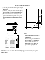
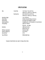
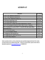
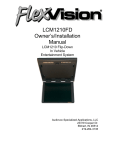
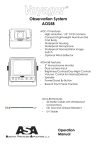
AWM820 Owner’s Manual
HIGH POWER AM/FM STEREO/CASSETTE PLAYER
DESIGNED SPECIFICALLY FOR
THE VAN AND RV INDUSTRIES
CAUTION: TO REDUCE THE RISK OF ELECTRIC SHOCK, DO NOT REMOVE COVER (ON BACK). NO USERSERVICEABLE PARTS INSIDE. REFER SERVICING TO QUALIFIED SERVICE PERSONNEL.
The lightning flash and arrowhead within the
triangle is a warning sign alerting you of
"dangerous voltage" inside the product.
The exclamation point within the triangle is
a warning sign alerting you of important
instructions accompanying the product.
WARNING: TO PREVENT FIRE OR SHOCK HAZARD, DO NOT EXPOSE THIS
APPLIANCE TO RAIN OR MOISTURE. DO NOT REMOVE COVER. PILOT LAMPS
SOLDERED IN PLACE. NO USER SERVICEABLE PARTS INSIDE. REFER
SERVICING TO QUALIFIED SERVICE PERSONNEL.
IMPORTANT NOTES
*Avoid installing the unit in locations described
below:
- Places exposed to direct sunlight or close to
heat radiating appliances such as electric
heaters
- On top of other stereo equipment that radiates
too much heat
- Places lacking ventilation or dusty places
- Humid or moist places
*Read Owner’s Manual before operating
*Be sure all connections are properly made
before turning power on.
IDENTIFICATION OF CONTROLS / CONNECTIONS
22
21
20
19
1
2 3 4
5
1)
2)
3)
4)
5)
6)
7)
8)
9)
10)
11)
12)
13)
14)
15)
16)
17)
18)
19)
20)
21)
22)
6
7
18
17
16
15
8
14
9
10
13
12
11
1
Tuning Up / Minute Set Button
Tuning Down / Hour Set Button
Mute / AS/PS / Loud Buttons
Time Set Button
Display Window
Alarm Set / Alarm On/Off Buttons
Button Reset
Preset Buttons
Cassette Fast Forward Button
Cassette Rewind Button
Cassette Player
Cassette Eject Button
Speaker Selector
1/8” Auxiliary Input Jack
Stereo Headphone Jack
Audio Adjust Button
Power Switch w/Volume Control
Source Selectors
Car Antenna Jack 75 Ω
FM Antenna Terminals
RCA Auxiliary Input Terminals
Harness
INSTALLATION AND HOOK UP
1) Cut mounting hole in desired location using mounting hole
diagram (right).
2) Route power, speaker, and antenna cables through hole,
and connect to unit as shown in hook up diagram below.
3) After making sure connections are correct, test unit
operation as described in the operation section (Do not
mount until AM antenna trimmer adjustment has been
made.
WIRING COLOR CODE
FOR AWM-820
COLOR
ORANGE/WHITE
GREEN/WHITE
BLACK/WHITE
WHITE
VIOLET
BLUE
LIGHT GREEN
RED
VIOLET/BLACK
YELLOW
LT.GREEN/BLACK
FUNCTION
+12VDC IGNITION POWER
+12VDC BATTERY POWER
TO CHASSIS GROUND
LEFT (A) SPEAKER (+)
LEFT (A) SPEAKER (-)
RIGHT (A) SPEAKER (+)
RIGHT (A) SPEAKER (-)
LEFT (B) SPEAKER (+)
LEFT (B) SPEAKER (-)
RIGHT (B) SPEAKER (+)
RIGHT (B) SPEAKER (-)
NOTES:
- Speakers must have a minimum of four Ω
impedance each.
- Either antenna may be used. Both do not
have to be hooked up at the same time.
- Do not operate this unit with only one
speaker hooked up. If a speaker fails,
replace it before operating this unit.
NOTE: Always be sure when running cables to avoid sharp edges, extreme heat sources, and any other
potential hazards.
2
OPERATING INSTRUCTIONS
NOTE: Number in parenthesis (#) corresponds with “Identification of Controls / Connections” on page 1 of this
manual.
LIQUID CRYSTAL DISPLAY PANEL
The liquid crystal display (LCD) panel displays the frequency, time, and activated functions.
Note: It is a characteristic of LCD panels that if subjected to cold temperatures for an extended period of time, they
will take longer to illuminate than under normal conditions. In addition, the visibility on the numbers of the LCD may
slightly decrease. The LCD read out will return to normal when the temperature increases to a normal range.
TUNER
1) Turn power on by pushing the Power Switch Control Button (17).
2) Use the Source Selectors (18), select the AM /FM button.
3) Use the Speaker Selector Switch (13) to choose between speaker output, headphones, or both.
4) Use Tuning Up (1) or Down (2) buttons to select the station manually. Also, the Station Preset buttons can select
stations (this will be discussed later in the manual). Push either of the Seek buttons (1 or 2) to tune to the next
higher or lower active station.
5) Adjust Volume Control (17) to suit taste.
CASSETTE TAPE PLAYER
1) Turn power on by pushing the Power Switch/Volume Control button (17).
2) Use the Source Selectors (18), to select the TAPE button.
3) Use the Speaker Selector Switch (13) to choose between speaker output, headphones, or both.
4) Press the Cassette Eject button (12) to eject any cassettes that may already be in the player.
5) Insert a cassette into the Cassette Player (11).
6) The cassette will automatically play when inserted.
7) You may rewind or fast forward the cassette using the REW or F.F. buttons (10 and 9).
8) To change sides of the cassette, press the REW and F.F. buttons (10 and 9), simultaneously.
9) To eject the cassette, press the Cassette Eject button (12).
3
AUXILIARY INPUT
1) Push Power Switch (17) “on”.
2) Using the Source Selectors (18), choose the button labeled “AUX”.
3) If there is an external source (ie. CD shuttle) connected to the Auxiliary In Jacks (21) on the rear of the radio,
then you can listen to your external source through the system.
4) An external auxiliary source can also be used (such as a portable cassette player) through the 1/8” Auxiliary
Stereo Input Jack (14) on the front of the radio.
SETTING THE CLOCK
1) Push the Power Switch (17) “on”.
2) Hold the T/ F button (4).
3) Use the H and M buttons (1 and 2) to adjust hours and minutes.
Note: The T/ F also toggles between time and radio frequency on the display.
SETTING STATIONS INTO MEMORY PRESET
1) This unit has the ability to set 18 FM and 12 AM stations into memory.
2) To set the AM or FM stations into memory, first tune to the desired station.
3) Once at the desired station, press and hold preset button (8) you wish to program for more than 3 seconds.
USING THE AUDIO ADJUST BUTTON
1) You can toggle between volume, treble, bass, and balance control by pressing the Audio Adjust button (16).
2) Once at the desired function, you can use the volume knob to adjust.
SETTING THE ALARM
1) Hold the Alarm Set button (6).
2) Use the H and M buttons (1 and 2) to adjust hours and minutes.
3) The Alarm On /Off button (6) activates or deactivates the alarm.
4
BEEP FEATURE
1) Hold the Audio Adjust button to enable the beep feature (16). Lower right side will display an audio symbol when
this feature is turned on.
2) When this feature is on, turning different features on or off will produce two different tones, higher tone for ON,
and lower tone for OFF.
3) Completely removing power from the unit will turn the beep feature off.
AS/PS BUTTON
This button is for Auto-Store Tuning (AS) and Pre-set Scan Tuning (PS) (3)
1) Press this button momentarily during radio operation to scan the stations pre-set into the memories of that band.
The unit will stop at each pre-set station for approx. 5 seconds before continuing on to the next pre-set station
Press this button again momentarily to stop pre-set scan operation and remain on the selected station.
2) Pressing this button for longer than 2 seconds will activate the Auto-store Tuning feature which will automatically
scan the band and enter up to 6 strong stations into the 6 pre-set memories (the indication “AST” will flash on the
display to show that Auto-store Tuning is in progress). After entering the stations into the memories, the unit will
automatically stop at each station for approx. 5 seconds so each can be heard.
NOTE: If you have already set the pre-set memories to your favorite stations, Activating the Auto-store feature will
erase those stations and enter the new strong stations.
5
SPECIFICATIONS
Size:
Overall Size
Mounting Size
Operating Voltage:
Output Power:
Output Wiring:
Output Impedance:
Tuning Range:
Sensitivity:
FM Stereo Separation:
Frequency Response:
Wow & Flutter:
Tape S/N Ratio:
10.43” (W) x 7” (H) x 6.25” (D)
265mm (W) x 178mm (H) x 159mm (D)
9.25” (W) x 6.05” (H) x 5.25” (D)
235mm (W) x 154mm (H) x 133mm (D)
10 to 16 Volts DC
50 Watts Total (25 Watts per Channel)
2/4 Speaker and Headphone System
Compatible with 4 to 8 Ω Speakers, 4 Ω load minimum
(AM) 530 -1720 KHz
(FM) 87.5 – 107.9 MHz
(AM) less than 30uv
(FM) less than 5uv
More than 24dB
40-12,000 Hz
0.15%
50dB standard tape
Designs and Specifications are subject to change without notice
6
ACCESSORY LIST
Description
AVT-988 9” Color Television with Remote (12V)
AVT-597 5” Color Television with Remote (12V)
AVT-1498 13” Color Television with Remote (12V)
AVP-7000 Video Cassette Player (12V)
AVP-7285 Video Cassette Player (12V)
Wireless Headphone Kit: Includes 2 sets Wireless Headphones and Transmitter
BPA-501-12 4 Amp Adapter for use with AVT-988 9” and AVT-1498 13” Televisions
AC2A- 2 Amp Adapter for use with AVT-597 5” TV and AVP-7000 Video Cassette Player
Unified Remote Control
VAC-21- 12 Volt Corded Vacuum
AVF-1 12 Volt Rechargeable Flashlight
HP-175 Headphones with Pivoting Ear Cup
HP-275 Headphones with Volume Control on Cord
HP-375 Studio Quality Headphones
Part Number
AVT988
AVT597
AVT1498
AVP7000
AVP7285
WRFKIT1
0891412
0891436
0892325
VAC21
AVF1
HP175
HP275
HP375
Unlike household electronics, all of our products have been specifically designed and tested for the mobile
environment and are only available through ASA. To order any of these products, please contact Audiovox
Specialized Applications at www.asaelectronics.com or 800-688-3135.
7
23319 Cooper Drive
Elkhart, IN 46514
(219) 264-3135 FAX (219) 264-3007
www.asaelectronics.com
Revision F
12/00