1
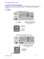
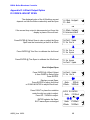
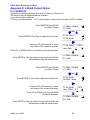
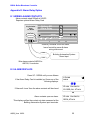
microFlex
Blowdown Controller
for Boilers
Measures Conductivity, Temperature,
Make-up Water Meter and Interlock
Controls the Blowdown Valve
and the Inhibitor Pump
Part No. BB-IN
BB-IN: Boiler Blowdown Controller
CONTENTS
Safety
1.
INSTALLATION
1.1
1.2
1.3
1.4
1.5
Sample Piping
Controller Enclosure
Sensor –Conductivity & Temperature
Sensors –Water Meter
Inhibitor Pump and Blowdown Valve
2.
START-UP
2.1
2.2
2.3
2.4
2.5
2.6
2.7
2.8
Power-up Display & Keypad
Blowdown Mode: Conductivity Setpoints
Inhibitor Feed Mode: Setpoints, Feed Limit
Verify Temperature
Calibrate Conductivity Sensor
Check Interlock & Install Water Meter
Plug-in Pump and Blowdown Solenoid
Check Controls
3.
OPERATION
3.1
3.2
3.3
3.4
3.5
3.6
3.7
Conductivity Sensor
Blowdown Controls
Make-up Meter
Inhibitor Controls
Diagnostics
System –Alarms
Password
4.
MAINTENANCE
4.1
4.2
4.3
Guidelines
Spare Parts
Technical Support
APPENDICES
A. INSTALL
B. SPECIFICATIONS
C. HARDWIRING
D. 4-20mA OUTPUT Option
E. ALARM RELAY Option
F. LAN - BROWSER Option
AQB2_User 02/06
2
BB-IN: Boiler Blowdown Controller
Safety
Electrical Shock Hazard
Opening the enclosure door with the controller plugged in,
exposes the user to AC line voltages.
Unplug the controller before opening the enclosure door.
USER WARNING : CAUTION
This Boiler Blowdown Controller operates a 120VAC blowdown valve or
steam rated solenoid & chemical feed pump and may pump hazardous,
corrosive and toxic chemicals.
Opening the controller enclosure exposes user to the risk of electrical shock
at power line voltages.
Understand fully the implications of the control setpoints, feed limit and
alarms that you select. Harm to personnel and damage to equipment may
result from mis-application.
Unplug or turn OFF the AC power to the controller if you have any concerns
regarding safety or incorrect controller operation and notify supervisory staff.
YOUR CONTROLLER
Controllers are supplied with default blowdown valve and inhibitor feed
setpoints that will not be applicable to your boiler.
Select control modes, adjust setpoints and set pump timing for your site and
its water treatment program.
AQB2_User 02/06
3
BB-IN: Boiler Blowdown Controller
1. INSTALLATION
1.1
Sample Piping
The Controller includes a 250psi steam rated conductivity sensor and ¾”sensorent
r
y‘
T’
and can be operated in either Sampling or Continuous Blowdown mode.
Sampl
epi
pi
ngi
spl
umbedi
n¾”schedul
e80bl
acki
r
onorst
eel
.
If you have not previously installed this type controller,
read Appendix A: INSTALL for plumbing and wiring guidelines.
Sampling Blowdown Control is the most commonly used blowdown method.
It provides the most accurate control at the lowest energy and chemical cost for most boilers
andi
t
’
sr
el
at
i
v
el
yi
nsensi
t
i
v
et
ot
hes
et
ting of the throttling needle valve.
AQB2_User 02/06
4
BB-IN: Boiler Blowdown Controller
Continuous blowdown control is an older method requiring a continuous
sample steam past the conductivity sensor.
It lacks the accuracy of Sampling blowdown control and is more difficult to set-up.
Percentage Time blowdown control mode uses the same piping configuration
as Continuous Blowdown Control
AQB2_User 02/06
5
BB-IN: Boiler Blowdown Controller
1.2
Controller Enclosure
Install the controller enclosure corner mounting hardware,
available in the parts bag stapled to the controller manual.
Locat
et
hec
ont
r
ol
l
eratey
el
ev
el
,60”
/
150cm.abov
et
hef
l
oor
Typical Equipment Layout
Downstream of
Deaerator
Controller
Plugs, wiring
& tubing not
shown
Inhibitor Pump
Chemical
Injection
point
Flow
Pump Shelf
NOTES
1. Controller is usually located within
sight of the blowdown valve.
2. Your installation may not include
chemical injection.
3. Chemical is usually injected
upstream of the feedwater pump
at deaerator pressure.
4. Conductivity sensor cable may
be extended up to 100ft in 4 x
AWG22
5. Do not cable sensor and 120VAC
valve wiring in the same conduit.
Inhibitor
Upstream
of Feedwater
Pump
Although sensor cables and pump tubing may be extended, ease of servicing occurs when
water treatment components are located in the same area.
Ensure that the controller enclosure door is closed & latched
when not terminating sensor and water meter wiring.
AQB2_User 02/06
6
BB-IN: Boiler Blowdown Controller
1.3
Sensors –Conductivity & Interlock
After isolating the surface blowdown line and installing the conductivity sensor, open the
sample piping downstream valve, then the upstream valve.
Verify that the sensor entry seals, leak and drip free
Conductivity - Temperature - Interlock
RUN
SENSOR
GRN WHT BLK RED
+15V
Flow
Meter
T S1 S2
White
Black
Black
White
Operating
Interlock
Dry contacts,
closed to operate
Jumper Flow to
if not used
Conductivity
Sensor
Note: The factory default
jumpers the interlock so
the controller will operate
out of the box .
Feed cables through the
entry seal & re-tighten
Controller
Thermally Compensated Conductivity Sensors
Compensated sensors are used for condensate monitoring –bypass controls
and for continuous blowdown controls with the compensated
sensor located downstream of a sample cooler.
Thermally compensated sensors are identified by a four wire sensor cable.
Connect the GREEN, WHITE, BLACK, RED cable to the
SENSOR GRN, WHT, BLK & RED terminals.
The controller will automatically measure the temperature
and thermally correct the measured conductivity.
AQB2_User 02/06
7
BB-IN: Boiler Blowdown Controller
1.4
Sensors –Water Meter
OPTIONAL SENSOR: Ref
ert
omanuf
ac
t
ur
er
’
sr
ecommendat
i
onsonmet
eror
i
ent
at
i
onand
upstream and downstream piping. Extend meter cables with AWG22, 2 or 3 conductor.
WARNING: Do not install water meters downstream of the feedwater pump.
Ensure that the temperature rating of the meter exceeds the feedwater temperature
Do not install meter cabling in the same conduit as AC power wiring.
AQB2_User 02/06
8
BB-IN: Boiler Blowdown Controller
1.5
Inhibitor Pump & Blowdown Valve
The controller supplies the AC power for the pump and blowdown valve or solenoid.
Controller relays switch power to the pump and blowdown solenoid,
fused at a maximum of 5 Amps.
MOTORIZED BLOWDOWN
VALVES are hardwired.
WARNING:
Do not plug-in controller, pump
or blowdown valve until you
are ready to setup & operate
STEAM RATED SOLENOIDS
may be plugged in or hardwired
INHIBITOR
PUMP - Back
SeeAppendi
x‘
C’
for Hardwiring
Grounded
Power Plug
BLOWDOWN
SOLENOID - Front
START-UP
BEFORE you plug-in the controller, set the throttling valve to 20% open,
open the surface blowdown line and sensor piping isolation valves.
WARNING: Plugging in the controller may immediately turn ON the blowdown valve.
Plug-in the controller.
Set control modes and setpoints.
Set the feed limit on the Inhibitor Pump.
Verify that the sensors are reading correctly and set the alarms.
If you are using a water meter,
verify that meter is measuring the expected volume.
Verify that the operating Interlock is working.
An overview of system operation is available in the Yearly section of 4.1 Maintenance.
AQB2_User 02/06
9
BB-IN: Boiler Blowdown Controller
2. START-UP
2.1 Power-up Display & Keypad
UP & DOWN to view options
or to EDIT numbers
Move RIGHT to select next
field when EDITing
ENTER to select an option
& to execute EDITing
EXIT to escape option,
info display or EDITing
Enclosure keypad
Response
UP or DOWN to the
display you wish to
view or EDIT
& press ENTER
Unique Controller Serial Number
Press ENTER for Controller Diagnostic,
And US-Metric select
Press ENTER to clear Alarms
Current Conductivity sensor value
Press ENTER for Conductivity Calibrate & Alarms
Valve ON or OFF and ON time this blowdown cycle
Press ENTER for Blowdown Setpoints, Mode,
Test and Current State
Water meter measured volume in most recent 0-24 hours.
Press ENTER to Install, Select type,
View on-line total & days on-line
Inhibitor Pump ON or OFF and ON time this feed cycle
Press ENTER for Inhibitor Setpoints, Feed Mode, Limit
Timer, Prime Pump and Current State
AQB2_User 02/06
Boiler Blowdown
S/N: D206NT248
Alarms
none
Conductivity
1425 uS
Blowdown Valve
ON
125.6min
16.4hr Make-up
8050 G
Inhibitor Pump
ON
96.4min
10
BB-IN: Boiler Blowdown Controller
2.1 Power-up Display & Keypad
continued
Interlock ON or OFF and ON time in most recent 24 hours
Reset to zero on POWER OFF/ON
Diagnostics since power ON
Reset to zero on POWER OFF/ON
Last blowdown, average blowdown, max-mi
nt
emper
at
ur
e….
If there is no option card installed
y
ou’
l
lv
i
ewt
heser
i
alnumber power-up display
LAN –Br
owser
,‘
LB’Opt
i
on
Displays current IP –s
eeAppendi
xF,‘
LAN’
f
orUserManual
Interlock
ON
780.6min
Diagnostics on
last 18.6hrs
Boiler Blowdown
S/N: D041B0248
LAN IP
010.010.006.101
OR
4-20mAOut
put
,‘
CL’Opt
i
on
Displays loop current –seeAppendi
xD,‘
4-20mAOUTPUT’
for User Manual
Al
ar
m Rel
ay
,‘
AR’Opt
i
on
Displays relay state –seeAppendi
xE,‘
ALARM RELAY’f
or
User Manual
AQB2_User 02/06
4-20mA Output
15.4mA
OR
Alarm Relay
Closed
11
BB-IN: Boiler Blowdown Controller
2.2 Blowdown Mode: Conductivity Setpoints
Thef
ac
t
or
ydef
aul
tBl
owdownModei
s‘
Sampl
i
ngCont
r
ol
’
Refer to 3.2 Blowdown Controls
to select one of three Blowdown Modes
Press UP or DOWN until you see
Blowdown Valve & press ENTER
Press ENTER to view or adjust Setpoints
Displays current blowdown setpoints,
Display varies with Blowdown Mode
Press ENTER adjust Turn ON,
or DOWN & ENTER for TurnOFF
Press UP-DOWN to adjust and RIGHT to move the cursor.
Press EXIT to leave the Setpoints unchanged
Press ENTER, displays current Setpoints.
If you make Turn ON less than TurnOFF,
the setpoints will be switched.
Set
poi
nt
sf
or‘
Sampl
i
ng’&‘
Cont
i
nuous’Blowdown Mode
Blowdown Valve
ON
2.7 hrs/day
Setpoints
Blowdown Mode
Turn ON
TurnOFF
3000
2990
Edit & Enter
Turn ON 3025
then
Turn ON
TurnOFF
3025
2990
Turn ON
TurnOFF
3000
2990
Continuous Control
Set
poi
nt
sf
or‘
Per
cent
ageTi
me’Blowdown Mode
Percentage Time
15% each 5min
% Time Control
Sidebar: Thedi
f
f
er
enc
ebet
weenTur
nON&Tur
nOFF,t
he‘
deadband’
,i
sus
ual
l
ysett
o10uS.
For‘
Sampl
i
ng’bl
owdownmodeand50uSf
or‘
Cont
i
nuous’bl
owdownmode.
Conductivity should decrease as Blowdown Valve ON time increases.
AQB2_User 02/06
12
BB-IN: Boiler Blowdown Controller
2.3
Inhibitor Feed Mode: Setpoints, Feed Limit
The factory default Feed Mode i
s‘
Per
c
ent
ageTi
me’
Refer to 3.6 Inhibitor Controls
to select one of three Feed Modes
Press UP or DOWN until you see
Inhibitor Pump & press ENTER
Press ENTER to view or adjust Setpoints
Displays current feed setpoints,
Inhibitor will be ON for 10% of the time that the Interlock is
ON; 30 seconds in every 5 minutes
Press ENTER adjust % of ON time.
Press UP-DOWN to adjust and RIGHT to move the cursor.
Press EXIT to leave the Setpoint unchanged
Press ENTER, displays current setpoint,
36 seconds in every 5 minutes
If Feed Mode is set to ‘
Bl
owdown&Feed’
Inhibitor Pump is ON for user set % of each blowdown.
Inhibitor Pump
ON
0.5min
then
Setpoints
Feed Mode
Percentage Time
10% each 5min
Edit & Enter
12% each 5min
then
Percentage Time
12% each 5min
Blowdown & Feed
17% each 5min
Blowdown & Feed
If Feed Mode is set to ‘
FeedonVol
ume’
Inhibitor Pump is ON for user set seconds for each user set
make-up volume.
Measure
100 G
Feed
12 sec
Feed on Volume
Si
debar
:‘
Per
cent
ageTi
me’
,basef
eedi
ngi
st
hemostcommonwayt
of
eedi
nhi
bi
t
orinto small
boilers which usually do not have a softened make-up or feedwater meter.
If you are using the Operating Interlock, chemical feed stops when the boiler is off line.
If your % condensate return is fixed and the blowdown control is reliable, consider using
‘
Bl
owdown&Feed’
.
If you have a water meter on the softened make-upuse‘
FeedonVol
ume’
Operating Interlock is a set of dry contacts which open when the boiler is off line.
When the Interlock contact set opens, blowdown and chemical feed stop.
The Interlock contact set may be supplied by the building automation system or the boiler
burner control.
AQB2_User 02/06
13
BB-IN: Boiler Blowdown Controller
2.3 Inhibitor Feed Mode: Setpoints, Feed Limit
continued
The Inhibitor feed limit timer turns OFF the inhibitor pump to
prevent overfeeding.
The factory default feed limit 20 Minutes per feed cycle.
Press UP or DOWN until you see
Inhibitor Pump & press ENTER.
Press DOWN until Limit Timer.
Press ENTER to view or adjust Limit Timer.
Displays feed limit in minutes,
?157 indexes more explanation @ www.aquatrac.com
Press ENTER adjust Feed Limit,
Press UP-DOWN to adjust and RIGHT to move the cursor.
Press EXIT to leave the Feed Limit unchanged
Press ENTER, displays current limit,
12 minutes per feed cycle
Inhibitor Pump
ON
48.1min
Limit Timer
Prime Pump
Feed Limit
18 min
?157
Edit & Enter
12 min
then
Feed Limit
12 min
?157
HELP: ?157 and other help numbers display wherever more explanation is available at
www.aquatrac.com. If you are using water treatment controls for the first time, the language
and application of some of the controller options and settings requires more detail than a 2 line
display can deliver.
AQB2_User 02/06
14
BB-IN: Boiler Blowdown Controller
2.4 Verify Temperature
OPTION: The default sampling blowdown controller does
not require or include temperature measurement.
Ensure that the conductivity sensor is immersed
at operating temperature.
Press UP or DOWN until you see Serial Number.
Press ENTER.
Press ENTER & then press ENTER
to view temperature at the conductivity sensor.
Asampl
i
ngbl
owdowncont
r
ol
l
erwi
l
ldi
spl
ay‘
-‘
With sensor type NT, No Temperature
Display on Thermally Compensated Sensor Connected
If the GREEN & WHITE wires are connected to the controller
t
er
mi
nal
s,y
ou’
l
lv
i
ewt
hecur
r
entt
emper
at
ur
e.
A low temperature may indicate a closed valve, upstream or
downstream of the sensor
Verify Temperature
Boiler Blowdown
S/N: D206NT248
Current State
Select Units
Temperature ?101
Type=NT
Temperature ?101
196F Type=NT
‘
Faul
t
’aut
omat
i
cal
l
yr
emov
esconduct
i
v
i
t
yt
emper
at
ur
e
compensation –see Sidebar.
Key EXIT twice to return to Serial Number
?101 indexes more explanation @ www.aquatrac.com
Sidebar: Continuous Blowdown Control
Temperature is used to compensate the measured conductivity. The temperature value does
not have to be accurate to correctly compensate but it does have to change as the boiler water
temperature at the sensor changes.
If you select Continuous blowdown control without a thermally compensated sensor, the
controller will display a Temperature alarm.
Sidebar: Sampling Blowdown Control
The temperature is not used to compensate the measured conductivity since the MEASURE
interval provides a fixed & repeatable temperature at the conductivity sensor.
AQB2_User 02/06
15
BB-IN: Boiler Blowdown Controller
2.5 Calibrate Conductivity Sensor
Open the downstream, then the upstream sample line
isolation valves, immersing the conductivity sensor.
Select Alarms then Clear Alarms to force a Sample &
Measure sequence. Calibrate after a Sample-Measure
sequence has updated Conductivity.
Press DOWN until you see Conductivity.
Sample the boiler water & verify that the displayed
conductivity matches the measured conductivity.
See Sidebar
Adjust the displayed conductivity by pressing ENTER twice.
Press UP-DOWN to adjust and RIGHT to move the cursor.
Press EXIT to leave Conductivity unchanged.
Calibrate Conductivity
Conductivity
1425 uS
Calibrate
Alarms
Edit & ENTER
1883 uS
then
You’
l
lseet
hi
sscr
eeni
ft
hes
ens
ori
sf
oul
ed,mi
swi
r
ed,
not immersed or you keyed incorrectly.
NOTE: Press ENTER to ignore OR
EXIT to return to Factory Default.
?141 indexes more explanation @ www.aquatrac.com
Displays the current, calibrated conductivity.
Advice
?141
Fails Calibrate
Conductivity
1883 uS
Sidebar:
Measuring boiler water conductivity requires a sample cooler to obtain a non-flashed sample.
Flashed samples of boiler water do not represent the boiler water conductivity.
A low temperature at the conductivity sensor indicates that the sensor is not measuring a hot
sample of boiler water. Do not calibrate a cold sensor.
Check the isolation valves upstream and downstream of the sensor, ensure the blowdown
valve is opening & closing and verify that the throttling valve is not blocked.
AQB2_User 02/06
16
BB-IN: Boiler Blowdown Controller
2.6 Check Interlock & Install Water Meter
Press UP - DOWN until you see Interlock.
Displays ON or OFF and the total minutes ON
in the last 24 hours.
NOTE: An OFF, open Interlock contact set stops
the inhibitor pump and the blowdown valve.
The Interlock can be bypassed by jumpering
the Flow terminal to
, Ground.
Controllers are shipped with the Interlock jumpered.
OPTIONAL: The factory default water meter is
a 100 Gallons/contact contact head meter
Press UP - DOWN until you see 0-24hr Make-up.
Displays make-up volume during the last 24 hours.
Make-up volume resets every 24 hours and
every power OFF/ON to 0.0 hours
Press ENTER twice to view or change meter type.
Key ENTER to view or change the gallons/contact.
Met
r
i
cuser
swi
l
lv
i
ewvol
umesi
n‘
L’
i
t
er
s&L/
Cont
ac
t
Press UP-DOWN to adjust and RIGHT to move the cursor.
Press EXIT to leave Gallons/contact unchanged.
Interlock
Interlock
ON
780.6min
Contact Head
Watermeter
24hr Make-up
10450 G
Meter Type
Year-to-Date
Contact Head
Paddlewheel
G/Contact
100
Edit & ENTER
25
then
ENTER or EXIT displays the current meter type.
Contact Head
Paddlewheel
Sidebar:
2 wire meters are usually Contact Head
3 wire meters are typically Turbine or Paddlewheel water meters.
Softened make-up water meters are lower cost ambient temperature rated meters.
Feedwater meters are usually high temperature paddlewheel type.
AQB2_User 02/06
17
BB-IN: Boiler Blowdown Controller
2.6
Check Interlock & Install Water Meter
continued
OPTIONAL: Turbine-Paddlewheel type water meters provide
pulses per Gallon or Liter.
ThenumberofPul
s
es/
Uni
tVol
umei
st
he‘
K’
f
act
or
.
Press UP - DOWN until you see 0-24hr Make-up.
Displays make-up volume during the last 24 hours.
Fewer hours are displayed if the controller
has not been ON for 24 hours
Press ENTER twice to view or change meter type.
Key DOWN to select Paddlewheel type meter
Turbine –Paddlewheel
Watermeter
6.4hr Make-up
31450 G
Meter Type
Year-to-Date
Paddlewheel
Contact Head
Key ENTER to view or change the pulses per Gallon.
Metric users view pulses per Liter.
‘K’Factor
100.0
Press UP-DOWN to adjust and ‘
K’Fact
orunchanged.
Edit & ENTER
104.5
then
ENTER or EXIT displays the current meter type.
Paddlewheel
Contact Head
Sidebar: A typical operating boiler will require softened make-up.
If a make-up meter exists, take the time to verify that the meter displays an
increasing volume as the boiler operates.
An accurate and working make-up or feedwater meter is required to meter inhibitor feed using
‘
FeedonVol
ume’mode.
Dry contact closures from the boiler feedwater pump are frequently used to control chemical
feed. Whenever the pump turns ON, the controller measures a user set volume of make-up.
WARNING: Verify paddlewheel meters immediately and disconnect if not verified.
Mis-wired paddlewheel meters will fail the meter Hall Effect sensor.
AQB2_User 02/06
18
BB-IN: Boiler Blowdown Controller
2.7
Plug-in Pump and Blowdown Solenoid
Sections 2.1 to 2.6 adjust setpoints and verify sensors.
We’
r
enowr
eadyf
ort
hebl
owdownsol
enoi
dandt
hei
nhi
bi
t
or
pump,v
er
i
f
y
i
ngeachoneasi
t
’
spl
uggedi
n.
(Blowdown motorized ball valves are hardwired)
Plug the blowdown solenoid into the top, right plug.
Press UP or DOWN to view Blowdown Valve.
If ON, verify that the green Bleed light
on the inside of the enclosure is ON.
Blowdown Valve
Blowdown Valve
ON
12.4min
OR
Verify that the blowdown valve is open
and that boiler water is going to the flash tank.
See Sidebar.
Blowdown Valve
OFF
126.8min
then
If OFF, press ENTER & DOWN to Test Valve.
Press ENTER and the Blowdown & Bleed light
will turn ON for 5 minutes
Plug the inhibitor pump into the bottom, right plug.
Press UP or DOWN to view Inhibitor Pump.
If ON, verify that the green Inhibit light
on the inside of the enclosure is ON.
Test Valve
Current State
Inhibitor Pump
Inhibitor Pump
OFF
then
Verify that the pump is stroking, primed and feeding inhibitor.
If OFF, press ENTER & DOWN to Prime Pump.
Press ENTER and the Inhibitor Pump & Inhibit light
will turn ON for 5 minutes
Prime Pump
Current State
Inhibitor Pump
ON
0.2min
Sidebar: The Blowdown Valve and Pump will not turn ON unless the Interlock is ON.
The internal Bleed & Inhibit lights will not turn ON unless the Flowswitch is ON.
An IR, non-contact temperature meter is the easiest way to verify that valves are open and that
there is a high temperature path past the sensor to the flash tank.
AQB2_User 02/06
19
BB-IN: Boiler Blowdown Controller
2.8 Check Controls
Verify that the controls work in the way
that you expect for this site.
Watch the Conductivity increase as the boiler operates.
Sampling controls update the Conductivity
at the end of every Measure period.
The Blowdown Valve will turn ON during Sampling and as
the conductivity exceeds the Turn ON setpoint.
Conductivity & Blowdown
Conductivity
1425 uS
Blowdown Valve
ON
17.1min
Sampling Controls will cycle between the Blowdown and
Measure states. Refer to Section 3.2 for details.
Water Meter or Bleed
& Inhibitor Pump
If the Inhibitor feed mode is set to Percentage Time and the
% of each 5 minutes is set to less than 100% the Inhibitor
Pump will turn ON & OFF while Interlock is ON.
Blowdown Valve
ON
124.2min
If the Inhibitor feed mode is set to Blowdown & Feed, the
Inhibitor Pump will turn ON as soon as the Bleed turns ON.
The pump will turn ON & OFF to meet the % setpoint in each
blowdown period.
Inhibitor Pump
ON
48.1min
24hr Make-up
10450 G
If the inhibitor pump is set to Feed on Volume , the inhibitor
pump will turn ON after measuring Make-up.
.
Inhibitor Pump
ON
124.8min
Sidebar: The Blowdown Valve and Pump will not turn ON unless the Interlock is ON.
The Inhibitor Pump turns OFF if the Feed Limit is exceeded.
Increase the Limit Timer to allow the pump to turn ON.
Feed limited inhibitor pumps reset every 24 hours of controller run time or on power OFF/ON.
AQB2_User 02/06
20
BB-IN: Boiler Blowdown Controller
3. OPERATION
3.1 Conductivity Sensor
Sensor calibration is detailed in Section 2.5
Alarms
Press UP - DOWN until you see Conductivity.
Press ENTER & then DOWN to Alarms.
Press ENTER to view current alarms or adjust
Press ENTER to adjust the High Alarm
or DOWN & ENTER to adjust the Low Alarm
Press UP-DOWN to adjust and RIGHT to move the cursor.
Press EXIT to leave Alarm unchanged.
ENTER updates the alarms & displays the
current High & Low Alarms.
Conductivity Alarms display on the ‘
Alarms’di
spl
ay
and resets automatically.
Conductivity
1425 uS
Calibrate
Alarms
Alarms
Calibrate
High
Low
3500uS
2500uS
Edit & ENTER
High 375 0uS
then
High
Low
3750uS
2500uS
‘
Cl
earAl
ar
ms’does not reset a conductivity alarm above the
High or less than the Low Alarm level.
Sidebar: Conductivity alarms may occur when the boiler is offline and the sensor is cold.
The alarm clears automatically when the sensor measures a hot boiler water sample and the
measured conductivity in between the High & Low alarm levels.
AQB2_User 02/06
21
BB-IN: Boiler Blowdown Controller
If Blowdown Mode is set to Sampling,
the Conductivity display updates at the end of each
Measure period.
Sensor Watch shows the conductivity continuously,
revealing problems with valves & flashing.
Press UP - DOWN until you see Conductivity.
Press ENTER & then DOWN to Sensor Watch.
(This option only displays when
Blowdown Mode = Sampling)
Press ENTER to view current sensor conductivity.
Press Exit to end watching
Sensor Watch
Conductivity
1425 uS
Calibrate
Alarms
Alarms
Sensor Watch
Sensor Watch
Calibrate
Watching
?254
655 uS
Sidebar: Sensor Watch
Sampling or Blowdown: The valve opens and Conductivity increases as the sensor heats up.
I
ft
heconduc
t
i
v
i
t
ydoes
n’
tchange,t
hev
al
v
edi
dn’
topenoranupst
r
eam ordownst
r
eam
isolation or throttling valve is closed. Correct this fault!
I
ft
heconduc
t
i
v
i
t
yi
sunst
abl
e,showi
ngv
al
uesl
esst
han200uS,i
t
’
sl
i
kel
y
,t
hatf
l
as
hi
ng is
occurring, indicating a partially closed valve or orifice union upstream of the sensor. Correct
this fault!
Measure: The valve closes. Sensor Watch displays a stable value, falling as the sensor cools.
If the Sensor Watch displays a low value and the boiler has cycled up to operating,
conductivity, the sensor may be partially immersed, measuring a mix of vapor and water.
Correct this fault!
If Sensor Watch displays a value which does not fall or a value which moves up and down, the
blowdown valve may not have closed or may have closed but not sealed (more common with
blowdown solenoids). Correct this fault!
AQB2_User 02/06
22
BB-IN: Boiler Blowdown Controller
3.2 Blowdown Control
For conductivity control setpoints Section 2.2
Blowdown Mode: Conductivity Setpoints
Press UP - DOWN until you see Blowdown Valve.
Displays ON or OFF and ON time in the
current 24 hour period.
Press ENTER to view or adjust Setpoints.
Setpoints vary with selected Blowdown Mode.
Blowdown Menu
Blowdown Valve
ON
8.7min
Setpoints
Blowdown Mode
Press ENTER view current mode or to select from
Sampling, Continuous or Percentage Time.
Blowdown Mode
Test Valve
Press ENTER @ Test Valve to turn ON Blowdown Valve.
See Sidebar.
Alarms-Clear Alarms ends the test.
Test Valve
Sample Timing
Sample Timing is only displayed if
Blowdown Mode = Sampling
Press ENTER to view or adjust Sampling timing.
Sample Timing
Current State
Press ENTER @ Current State to view control status.
Display varies with Blowdown Mode
Current State
Setpoints
Sidebar: Test Blowdown will not turn ON the Blowdown Valve unless the Interlock is ON.
Warning: Changing Blowdown Mode may require plumbing changes.
See manual Section 1.1 for piping configuration is each mode.
Test Valve starts a Sample period if Blowdown Mode = Sampling.
Alarms –Clear Alarms, also starts a new Sample period if Blowdown Mode = Sampling.
Test Valve turns ON the Blowdown Valve for 5 minutes, 300 seconds,
if Blowdown Mode = Continuous or Percentage Time
AQB2_User 02/06
23
BB-IN: Boiler Blowdown Controller
3.2 Blowdown Controls
Continued
Blowdown Valve Modes
Press ENTER then DOWN @ Blowdown Valve
Blowdown Valve
ON
21.8min
then
Press ENTER @ Blowdown Mode to view current mode and
to select a new mode
Blowdown Mode
Test Valve
Most boilers operate with Sampling blowdown control.
The Blowdown Valve opens to Sample the conductivity.
If above the TurnON setpoint, Blowdown-Measure periods
occur until below the TurnOFF setpoint.
If below the TurnON setpoint, waits ReSample time
until next Sample.
Continuous control turns ON the Blowdown Valve above
the TurnON setpoint and OFF below the TurnOFF setpoint.
Percentage Time turns ON the Blowdown Valve
for a user set % of 5 minutes if Interlock is ON.
Sampling
Continuous
Continuous
Percentage Time
Percentage Time
Sampling
then
NOTE: If you change the Blowdown Mode, press UP to
Setpoints & ENTER to adjust for the new Blowdown Mode.
Warning: See Sidebar
Setpoints
Blowdown Mode
Sidebar:
Warning: Changing Blowdown Mode may require plumbing changes
See manual Section 1.1 for piping configuration is each mode.
Sampling control requires the blowdown valve downstream on the conductivity sensor.
Continuous and Percentage Time modes require the Blowdown Valve parallel to the sensor
piping so the sensor can continuously read the boiler water conductivity.
AQB2_User 02/06
24
BB-IN: Boiler Blowdown Controller
3.2 Bleed Controls
Continued
Current State of the Blowdown Valve Control
Press ENTER then UP @ Blowdown Valve
Blowdown Valve
ON
21.3min
then
Press ENTER @ Current State
Displays Sampling OR Measure OR B’
downOR Waiting
Counts down time in the current state.
Key ENTER to end the state and go to next state
Current State
Setpoints
ON,Sampling ?250
11 sec. Stop=
Sampling Control
If ON, displays TurnOFF setpoint,2990
& current conductivity,3042.
If OFF, displays TurnON setpoint,3000
& current conductivity,2993
If ON, displays Owes 41 sec ?123
& ON ENTER=Stop
If OFF, displays seconds to turn ON,
Off@ 2990
ON 3042uS
?121
Continuous Control
On in 221sec?123
OFF
% Time Control
HELP:
?250,122 & ?123 and other help numbers display wherever more explanation
is available at www.aquatrac.com.
Stop=
ends the current Sampling control period and starts the next period.
If you Stop the Measure period you will measure a high conductivity.
If you Stop the Sample period you may not measure a fresh,
representative sample of boiler water
The Blowdown Valve is ON, open during the Sample & B’
downperiods and OFF, closed
during the Measure and Waiting periods.
ON ENTER=Stop ends Percentage Time blowdown control mode ON period.
AQB2_User 02/06
25
BB-IN: Boiler Blowdown Controller
3.2 Bleed Controls
Continued
Sampling Control Mode Timing
Press ENTER then UP @ Blowdown Valve
Blowdown Valve
ON
21.3min
then
Press ENTER @ Sample Timing
to view or adjust timing.
This option only displays if Blowdown Mode = Sampling.
Key DOWN to view current Sample, Measure,
Bl
ow’
dwn& ReSample times.
Key ENTER to adjust.
Key UP & DOWN to adjust.
EXIT ends with changing the time.
ENTER ends adjust and executes the new timing.
I
nt
hi
sex
ampl
ewe’
v
ei
ncr
easedt
heSample time from 20
seconds to 28 seconds.
Sample Timing
Setpoints
Sample
Measure
20s
30s
Edit & Enter
Sample
28
then
Sample
Measure
28s
30s
Sample: May be set a short as 5 seconds if the sensor is located at the boiler or as long as 60
secondsf
orasensor100f
eetf
r
om aboi
l
er
.I
t
’
st
het
i
mer
equi
r
edt
of
i
l
lt
hepi
pi
ngbet
ween
boiler & sensor and reflects both the length of pipe and the setting of the throttling valve.
Measure: Usually never less than 30 seconds. May be as long as 120 seconds. Allows a
stable sample with a fixed and repeatable amount of cooling.
Bl
ow’
dwn:Never less than Sample time seconds & typically no more than 5 times Sample
t
i
me.Thec
onduct
i
v
i
t
yi
scheckedev
er
yBl
ow’
dwnt
i
me&Bl
ow’
dwncont
i
nuesi
fc
onduct
i
v
i
t
y
above TurnOFF setpoint. Long Bl
ow’
dwntimes may overblow the boiler.
ReSample, Waiting: As short as 15 minutes for heavily loaded boilers that increase
conductivity rapidly. Typically 30 minutes to 4 hours. May be as long as 12 hours for stand by
boilers. ReSample is the time between conductivity checks when the conductivity is less than
TurnOFF setpoint.
AQB2_User 02/06
26
BB-IN: Boiler Blowdown Controller
3.3 Make-up Meter
OPTIONAL: Meter type selection & installation detailed in
Section 2.5 Check Interlock & Install Water Meter
Press UP - DOWNunt
i
l
y
ousee’
0-24 hr Make-up’
& press ENTER .
18.2hr Make-up
10450 G
Press ENTER to view current type or to select
Contact Head or Paddlewheel water meter.
Meter Type
Year-to-Date
Key DOWN & ENTER for volume during the most
recent 365 days. Resets to zero every 365 days.
Year-to-Date
Days Online
Key DOWN & ENTER for the number of 24 hour periods of
ON time in the current year
Days Online
Zero Meter?
Key ENTER to reset Year-to-date, Days OnLine
and 24 hr Make-up to zero.
Warning: Cannot Undo
Zero Meter?
Meter Type
Year-to-Date logged every 60 minutes power ON.
Displ
ay
si
n‘
L’
i
t
er
si
fmet
r
i
csel
ect
ed.
Days water meter ON in current year.
Resets to zero every 365 days.
Year-to-Date?192
265200 G
Days Online ?193
28.7
Press EXIT to return to previous display
Sidebar: Year-to-date divided by Days OnLine is average usage in any 24 hour period.
HELP: ?192 & ?193 and other help numbers display wherever more explanation is available at
www.aquatrac.com.
AQB2_User 02/06
27
BB-IN: Boiler Blowdown Controller
3.4 Inhibitor Controls
For inhibitor control setpoints & feed limit, refer to
Section 2.3 Inhibitor Feed Mode: Setpoints, Feed Limits
Press UP - DOWN until you see Inhibitor Pump.
Displays ON with time on in the current 24 hour period.
Press ENTER to view or adjust Setpoints.
Setpoints vary with selected Feed Mode.
Press ENTER view current mode or to select from
Blowdown & Feed, Feed on Volume, Percentage Time.
Press ENTER to set maximum Inhibitor Pump ON time
in minutes in any 24 hours
Press ENTER @ Prime Pump to turn ON Inhibitor Pump
for 5 minutes. Alarms-Clear Alarms ends Priming.
Press ENTER @ Current State to view control status.
Display varies with Feed Mode
Inhibitor Pump Menu
Inhibitor Pump
ON
3.1min
Setpoints
Feed Mode
Feed Mode
Limit Timer
Limit Timer
Prime Pump
Prime Pump
Current State
Current State
Setpoints
Sidebar: Prime Pump will not turn ON the pump unless Interlock is ON.
Inhibitor pumps with Feed Mode set to Blowdown & Feed will not feed unless the Blowdown
Valve is ON.
AQB2_User 02/06
28
BB-IN: Boiler Blowdown Controller
3.4 Inhibitor Controls
Continued
Inhibitor Pump Feed Modes
Press ENTER then DOWN @ Inhibitor Pump
Inhibitor Pump
ON
12.3min
then
Press ENTER & DOWN @ Feed Mode to view
current mode and to select a new mode
Feed Mode
Limit Timer
Percentage Time turns ON the Inhibitor Pump
for a user set % of 5 minutes if Interlock is ON.
Percentage Time
Feed on Volume
Feed on Volume measures a user set volume on
the Make-up water meter then turns ON
the pump for a user set time.
For example:
Measure 100 Gallons of make-up & feed for 8 seconds.
Feed on Volume
Blowdown & Feed
Inhibitor Pump turns ON when the Blowdown Valve is ON.
Pump switches ON & OFF during bleed
at user set % of 5 minutes
Blowdown & Feed
Percentage Time
then
NOTE: If you change the Feed Mode, press UP to Setpoints
& ENTER to adjust for the new Feed Mode.
Setpoints
Feed Mode
Sidebar:
Percentage Time is used to base feed & is the most commonly used chemical feed method
for smaller boilers.
Feed on Volume is an accurate & reliable way to feed chemical for boilers which have a
softened make-up meter or a dry contact closure from the feedwater pump.
Blowdown & Feed requires reliable blowdown control and conductivity tracking.
The setpoint % time is based on either the sum of Sample + Measure time or Blowdown +
Measure time. The sum of periods is used since a boiler that is blowing down may require a
number of Blowdown-Measure cycles to fall below the TurnOFF setpoint.
Chemical is lost any time the blowdown valve is open, so feed is based on both Sample and
Blowdown periods.
AQB2_User 02/06
29
BB-IN: Boiler Blowdown Controller
3.4 Inhibitor Controls
Continued
Current State of the Inhibitor Pump Control
Inhibitor Pump
ON
0.5min
Press ENTER then UP @ Inhibitor Pump
then
Press ENTER @ Current State
If Feed Mode = Blowdown & Feed
If Sampling or Blowing Down, displays
Owes 162sec ?154
OR On in 86sec ?150
If Blowdown Valve OFF: displays Blowdown Off ?150
If ON, displays Owes 41 sec ?156
and ENTER=Stop
If OFF, displays seconds to turn ON,
Current State
Setpoints
Owes 162sec ?154
ON ENTER=Stop
Blowdown & Feed
On in 267sec?156
OFF
If ON, displays Owes 38 sec ?154
If OFF, displays turn-on volume, 9800
& current volume 9700
Percentage Time
On@
OFF
9800 G ?155
9700 G
Feed on Volume
Sidebar:
Blowdown & Feed applies the user set %of Blowdown valve ON time
to each 300 seconds of Blowdown Valve ON time.
ON ENTER=Stop ends the current feed cycle or %Time ON period.
HELP: ?150,?154,?155 & ?156 and other help numbers display wherever more explanation is
available at www.aquatrac.com.
AQB2_User 02/06
30
BB-IN: Boiler Blowdown Controller
3.5 Diagnostics
Diagnostics displays operating information
from the last power OFF/ON.
Average Blowdown & Temperature MAX-MIN
are reset on every power ON
Diagnostics on
last 6.3 days
The time that the Blowdown Valve is open depends on
throttling valve %open, load and conductivity setpoints.
Last B’dwn ON
14.9 min.
A loaded boiler will blowdown more frequently
than a standby boiler.
Boilers in commercial-institutional sites will blowdown
frequently during business hours.
B’dwn ended
86.9 min. ago
Increasing Average Blowdown time may indicate a change
in make-up chemistry or a restricted bleed
or a higher boiler load.
Average B’dwn
10.6 min.
Pump ON time verifies setpoints and feed mode selection.
For example: If you are feeding ‘
Bl
owdown&Feed’at 25%
of bleed time & the Last Bdown ON = 5 min
then Last Feed ON = 75 sec.
Last feed ON
26 sec.
If your Inhibitor Pump is controlled by the Blowdown Valve,
you would see that the last Feed Ended
when the B’
dwnEnded.
If your Inhibitor Pump is controlled by the Make-up,
you would see that the last Feed Ended when
the Last make-up. occurred
If the Last make-up occur
r
edsev
er
alday
sago,t
her
e’
s
understandably a metering problem
Requires optional thermal sensor:
Temperature max-min may reflect variation in sample
cooler water temperature or condensate usage if used for
condensate monitoring
The usefulness of Diagnostic information varies with each
si
t
e’
sboi
l
er
,pi
pi
ng,wat
erchemi
st
r
yandt
r
eat
mentpr
ogr
am.
AQB2_User 02/06
Feed ended
1.2 hrs ago
Last make-up
58.4 min. ago
Temperature
194max, 182min
Last B’dwn ON
14.9 min.
31
BB-IN: Boiler Blowdown Controller
3.6 System- Alarms
System Menu Options
Press UP - DOWN until you see the Serial Number.
Press ENTER view System options.
Boiler Blowdown
S/N: D041B0248
Press ENTER to view Current State
Controller diagnostics
Current State
Select Units
Press ENTER to view or change
US or Metric units.
Select Units
Current State
Alarms
Press UP - DOWN until you see Alarms
Thef
i
r
stal
ar
mt
ot
r
i
pwi
l
ldi
s
pl
ayor‘
none’i
fnoal
ar
ms
Press ENTER to Clear Alarms.
Clearing alarms sets pump & blowdown owed times to zero.
Alarms
none
Clear Alarms
SensorAl
ar
ms,
’
Out
-of-Cal
i
br
at
i
on’andSy
st
em Alarms
auto-clear when the fault is corrected
Sidebar: If Blowdown Mode = Sampling
A. Clear Alarms starts a new Sampling period.
B. A Fail-to-Sample alarm indicates a low temperature at the sensor at the end of the
Measure period. The Blowdown Valve has failed to operate,
an isolation valve upstream or downstream of the sensor is closed,
t
het
hr
ot
t
l
i
ngv
al
v
ei
scl
osedorbl
ock
ed…
Blowdown control will not work correctly until this fault is corrected.
Find & fix the cause, Clear Alarms to start a new Sample period
AQB2_User 02/06
32
BB-IN: Boiler Blowdown Controller
3.6 System- Alarms
continued
System : Current State
Press UP - DOWN until you see the Serial Number.
Press ENTER view System options.
Press ENTER to view Current State
Controller diagnostics
Temperature at the conductivity sensor.
Di
spl
ay
s‘
Faul
t
’i
fnotusedt
ocompensat
ec
onduct
i
v
i
t
y
,
Indicates wiring or sensor problem.
Power used for paddlewheel water meters
and to power 4-20mA current loops
Alarms on short circuits, recovers when wiring corrected.
Boiler Blowdown
S/N: D041B0248
Current State
Select Units
Temperature ?101
341 F
Ext. Power ?102
15.6 VDC
Internal power used for blowdown valve and pump relays.
Always 11.8 to 12.2.
Alarms on fault.
Relay Power ?103
12.1 VDC
Conductivity sensor drive, 72-76mV or 995 –1010mV
as sensor drive auto-ranges.
Alarms and cannot measure conductivity if out of range.
Drive
?107
73.3 mV
Internal diagnostics.
Checks that user setpoints being saved
& that the controller timing is operating,
Measure
?105
998.5 mV
State
244:163
?106
Sidebar: System: Diagnostics verifies the controller operation & alerts you to wiring problems
with conductivity temperature, paddlewheel water meters and controller powered 4-20mA
current loops.
AQB2_User 02/06
33
BB-IN: Boiler Blowdown Controller
3.6 System- Alarms
continued
System : Select Units
Press UP - DOWN until you see the Serial Number.
Press ENTER & DOWN to Select Units
Boiler Blowdown
S/N: D041B0248
then
Press ENTER to view or adjust current Select Units.
Select Units
Current State
Press EXIT to leave changed
or DOWN to change.
Deg F, Gallons
Deg C Liters
Key ENTER to:
Set to U.S. units, degrees Fahrenheit & Gallons
Or
Set to Metric, degrees Centigrade & Liters
Deg C Liters
Deg F, Gallons
Sidebar:
Select Units changes make-up meter units, total volume units and volume per contact units.
Temperature compensation of conductivity, switches automatically between Centigrade &
Fahrenheit as does the System / Current State display of temperature.
AQB2_User 02/06
34
BB-IN: Boiler Blowdown Controller
3.7 Password
Password is turned OFF in new controllers
Press UP - DOWN until you see Boiler Blowdown.
Press ENTER & DOWN to select Password ON
Turning ON Password
Boiler Blowdown
S/N: D206NT042
Current State
Select Units
&
If you press ENTER y
ou’
l
lbepr
ompt
edf
orapassword then
next time you press ENTER.
Password ON
Current State
Password ON
Press UP or DOWN to view the current state of the controller.
Any ENTER key will prompt for the password,
displaying the default password 123.
Enter Password
000123
then
Use the UP, DOWN & RIGHT keys to enter a password
then key ENTER.
A correct password displays, Password OK.
Press any key to start operating the controller.
Press ENTER to re-key an incorrect password
Advice
?110
Password OK
OR
Advice
?111
Wrong Password
Sidebar: When you first select Password ON, the default password is 123.
Whenever you Enter Password the controller displays the default password 123.
If you have not changed the default password, press ENTER to log in.
AQB2_User 02/06
35
BB-IN: Boiler Blowdown Controller
3.7
Password
continued
Press UP - DOWN until you see Boiler Blowdown.
Then press ENTER & UP to view Password tools.
Password
Current State
Password tools are available when Password is ON
and you are logged in. Press ENTER to view the tools:
Press ENTER to Log Out.
If you forget to Log Out, the controller logs you out
30 minutes after the last key press
and on controller power OFF/ON.
Press DOWN & then ENTER to view
& change the current password
Press DOWN to Password OFF.
Pressing ENTER turns OFF Password.
Log Out
Edit Password
Edit Password
Password OFF
Password OFF
Log Out
Edit Password
Press RIGHT & UP –DOWN to change
the current password.
Edit & ENTER
0094502
ENTER changes the password.
Press EXIT to leave the password unchanged
then
Log Out
Edit Password
Sidebar: If your controller is password protected. Select Edit Password and change the
passwor
df
r
om t
he‘
123’
f
act
or
ydef
aul
t
.
Passwords may be from 1 to 6 numbers. Leading zeros are ignored.
If you forget yourpass
wor
d,y
ou’
l
lr
equi
r
et
hecont
r
ol
l
erser
i
al
numbert
ogetaReset
Password from the controller manufacturer.
Thecont
r
ol
l
erpasswor
di
s‘
123’af
t
ery
oukeyi
nt
heReset Password.
AQB2_User 02/06
36
BB-IN: Boiler Blowdown Controller
4. MAINTENANCE
4.1 Guidelines
Modify the maintenance guidelines to reflect both the site priorities
and the site water treatment program.
Guidelines are for controller function only. Water treatment program maintenance
requirements are provided by the site water treatment provider.
Frequency
Daily
Activity
Check for Alarms.
Scan Sensors,
Make-up Meter
& Flowswitch
Method
Identify and correct the cause of alarms on sensors
and inhibitor pump.
Make-up water or Pump rate & stroke may have
changed.
The percentage of condensate return may have
changed, extending inhibitor ON times, changing
blowdown run times.
Debris may have partially blocked the blowdown line
throttling valve.
Sampling Blowdown: A low conductivity may indicate
a failure to sample resulting in a cold sample at the
sensor.
The blowdown valve may not be operating or may be
valved OFF, upstream or downstream of the valve.
Continuous Blowdown: A high conductivity may
indicate a blocked or failed blowdown valve.
I
ft
her
e’
sas
of
t
enedmake-upmet
er
,y
ou’
dex
pect
daily volume to vary with load if the % condensate
r
et
ur
ndoesn’
tv
ar
y
.Hi
ghmake-up may indicate a low
% condensate return or a faulted blowdown control.
If the boiler is on line, verify that the Interlock shows
ON.
At the same boiler load and percentage condensate
return, you would expect consistent and repeatable
Blowdown Valve and Inhibitor pump ON times in
every 24 hour period.
AQB2_User 02/06
37
BB-IN: Boiler Blowdown Controller
Frequency
Weekly
Activity
Verify Conductivity
Method
Sample the boiler water conductivity.
Verify controller matches sample +/-50uS.
Conductivity sensors should not drift or require
cleaning.
Scaling a conductivity sensor usually indicates
flashing at the sensor due to a restriction upstream of
the sensor.
Sampling Blowdown Control:
Temperature not used or measured during Sampling
blowdown control.
Check both current
Temperature and
Minimum-Maximum
temperature
Continuous Blowdown Control:
You would expect to see a relatively constant sensor
temperature with only a small difference between
Minimum & Maximum temperatures if the boiler
operates continuously.
You’
dex
pectt
oseeonl
yasmal
lchangei
nsensor
temperature when the blowdown valve opens
Note Make-up Volume Weekly softened make-up water usage indicates both
If make-up meter
average boiler load and percentage condensate
installed.
return.
High water usage may result from a reduction in
controller setpoints or faulted or failing softener.
Verify Interlock
If you are using the Interlock, verify that Interlock
shows OFF when the boiler is off line.
System Check
Visually inspect sensor and sensor piping for leaking
fittings. Inspect chemical injection tubing and entry for
leaking.
Sidebar: Maintenance Guidelines for water treatment testing are set by
the chemical treatment program vendor.
AQB2_User 02/06
38
BB-IN: Boiler Blowdown Controller
Frequency
Activity
Method
Yearly
Calibrate Conductivity
Tester
Verify the boiler water conductivity tester annually
with acal
i
br
at
i
ons
ol
ut
i
onusi
ngasol
ut
i
ont
hat
’
sas
close as possible to the controller conductivity
setpoints. Replace outdated calibration solutions.
Observe a Blowdown
Control Cycle
Sampling Blowdown Control:
How many Blowdown-Measure cycles does it take to
lower the conductivity below the TurnOFF setpoint.
If the conductivity is well below the TurnOFF setpoint,
i
t
’
sl
i
kel
yt
hatt
heBl
owdownt
i
mei
ss
ett
ool
ong.
If the conductivity increases markedly above the
TurnON setpoint, consider opening the throttling valve
to allow a higher blowdown rate. Check that the flash
tank can handle higher blowdown volumes.
Continuous Blowdown Control:
Watch the conductivity as the blowdown valve turns
ON. Does it fall immediately? You may not have
enought
hr
ot
t
l
i
ngont
hebl
owdownl
i
ne.You’
l
lseet
he
blowdown valve rapidly opening & closing, shortening
valve life.
Does the conductivity take a long time to increase,
even when the boiler is loaded. You may have to
throttle the sensor flow to limit heat & chemical loss.
Verify Water Meter
If a make-up water meter is installed, verify that the
controller measures an increase in make-up volume
when the boiler feedwater pump turns ON.
If you are using the meter to control inhibitor feed,
y
ou’
l
lbeawar
eoft
hepr
obl
em pr
i
ort
oanannual
check. Chemical levels will be either higher or lower
than target.
AQB2_User 02/06
39
BB-IN: Boiler Blowdown Controller
4.1 Spare Parts
4.1.1 Line Fuse
Protects
Rating / Type
Controller,
Pump and
Blowdown Valve
Manufacturer –Vendor
Littlelfuse, Type 217, 250VAC
5 Amps @ 115VAC Digikey Part# F953-ND
5mm x 20mm, www.digikey.com 1-800-344-4539
Fast Acting
4.1.2 Controller Parts
Part#
Description
SFuse
120VAC Fuse Kit, 10 x 5A Controller Fuses,
A261000
Boiler Conductivity-Temperature sensor,
¾”NPT,max
i
mum 250psist
eam
BB-IN-NS
Spare Controller without sensors & entry fittings
R171230
Enclosure Power cable entry fitting, PG11
R717231
Enclosure Sensor cable entry fitting, PG9
On-Line Help
Browse to www.aquatrac.com/help wi
t
ht
he3di
gi
tHELP#’
f
r
om t
hecont
r
ol
l
erLCDdi
spl
ay
.
LCD display HELPnumber
sar
epr
ec
ededby‘
?’
Users Manual
Download AQB2_User from www.aquatrac.com
Manual Version
03/06
AQB2_User 02/06
Detail
BB-IN Production
40
BB-IN: Boiler Blowdown Controller
Appendix A: INSTALL
A.1 PLUMBING
Safety:Fol
l
owt
hesi
t
e’
sv
al
v
eof
fandt
agoutpr
ocedur
espr
i
ort
omaki
nganypl
umbi
ng
changes to the surface blowdown line. Multiple boiler sites may require both more than one
upstream and downstream isolation valve.
Ensure the isolation and needle valves are rated for steam service at a pressure exceeding the
maximum expected steam pressure.
Plumb sensor piping in the same metallurgy and schedule as the surface blowdown line.
Warning: Throttling needle valves will block with flashed solids if not correctly installed. Follow
t
hemanuf
act
ur
er
’
sr
ec
ommendat
i
onf
orupst
r
eam-downstream orientation.
Remove needle valves and orifice unions upstream of the conductivity sensor.
A.2 SENSORS
Conduc
t
i
v
i
t
ysensor
smaybei
ns
t
al
l
edi
na¾”‘
T’i
nanyor
i
ent
at
i
on.
Donoti
ns
t
al
lsensor
si
n‘
T’
sl
ar
gert
han¾”
.Ther
equi
r
edr
educer
smayr
esul
ti
nanonimmersed or intermittently immersed sensing surface.
Water meter and sensor wiring cannot be installed in the same conduit as 120VAC power,
pump or blowdown valve wiring. Even a short section of shared conduit may cause operational
problems.
Sensor wires may be extended up to 200 hundred feet using multiple pair AWG22 cable.
Always splice sensor wires in an electrical fitting to allow both inspection and sensor
replacement.
Extend the conductivity sensor using the same colors as the sensor to avoid wiring errors at
the controller terminals.
Contact head water meters and interlock contact sets are not polarized, simplifying cable
extension.
CAUTION: Three wire turbine-paddlewheel meters are polarity sensitive and can be
permanently damaged by miswiring. Wait until you are ready to start-up the controller before
connecting this type of meter to the controller. Meter wiring errors are easily detected and
corrected at start-up.
A.3 CHEMICAL FEED
Si
ncet
hec
ont
r
ol
l
erf
eedsasi
ngl
ec
hemi
cal
,i
t
’
sl
i
kel
yt
obef
edi
nt
ot
hef
eedwat
erl
ine or
directly into the dearator sump.
Inject water treatment chemical upstream of the boiler feedwater pump where pressure and
temperature are limited to the deaerator sump levels.
The controller is not fused to power a fractional horsepower, piston drive chemical pump.
A motor start relay is required with the 120VAC coil powered by the controller.
AQB2_User 02/06
41
BB-IN: Boiler Blowdown Controller
A.4 BLOWDOWN VALVE & LOCATION
Steam rated solenoids are seldom used in boilers rated over 100psi steam. Steam rated
solenoids are commonly used and reliable on low pressure boilers. Solenoids have the added
advantage of being closed when solenoid power is OFF.
Motorized ball valves are typically the PowerON –PowerOFF type. AC power is required to
both open and close the valve.
If the controller is powered OFF when the valve is open, the valve will stay open. Although this
is seldom an operational problem, sites may elect to use a spring loaded return type ball valve
which does not require power to close.
PowerON-PowerOFF motorized blowdown valves require 3 wires & ground, Power Open,
Power Closed and Neutral.
Steam rated solenoids & Spring Return motorized valves require only 2 wires & ground, Power
Open and Neutral.
The optimum blowdown location is after the surface blowdown safety isolation valves, typically
in a vertical run, beside the boiler where the operation of the blowdown valve can be observed
and the distance between sensor and boiler minimized.
Orient the valve so that the valve state is easily viewed. Typically, motorized valves have a
shaf
tposi
t
i
oni
ndi
c
at
orsoi
t
’
seasyt
os
eet
hev
al
v
eoper
at
eandi
fi
t
’
scur
r
ent
l
yopenorcl
os
ed.
I
t
’
smor
edi
f
f
i
c
ul
tt
oseet
hes
t
at
eofast
eam r
at
eds
ol
enoi
d.Anon-contact, IR temperature
meter is a low cost, easy way to verify solenoid state by reading the temperature on either side
of the solenoid.
A.5 MAKE-UP METER
Ensure that the meter is rated for the temperature. Meters installed in feedwater lines,
upstream of the feedwater pump are typically stainless steel paddlewheel type.
Add meter isolation and/or bypass valves so the meter can be serviced.
Ensur
et
hatt
hemet
ermanuf
ac
t
ur
er
’
sr
ecommendat
i
onsf
oror
i
ent
at
i
onandupst
r
eam and
downstream piping are observed.
Horizontal installation may be limited for contact head meters, while straight upstream and
downstream piping is required to prevent errors in turbine-paddlewheel meters.
Contact head meters have a Gallon/Contact or Liter/Contact rating. In some meters this value
can be altered by moving magnets or gears. Typical meters are rated 10, 50 & 100
Gallons/contact.
Turbine-Paddl
ewheel
met
er
shav
ea‘
K’Fact
orwhi
chi
st
henumberofpul
ses/Gal
l
onor
pulses/Liter. Some manufacturers have both nominal values listed by meter size and
calibration values on the meter body.
Take the time togett
hemet
erv
ol
ume/
cont
ac
tor‘
K’
f
ac
t
orcor
r
ect
,si
ncemostmet
er
sar
eused
to control inhibitor feed and inhibitor ppm errors result when meters are incorrectly configured.
AQB2_User 02/06
42
BB-IN: Boiler Blowdown Controller
A.6 CONTROLLER ENCLOSURE
The optimum location for blowdown valve, sensor and controller allows the keypad user to see
the blowdown valve operate. Typically the chemical feed pump is more remote from the
controller, at the deaerator.
Wal
lmountt
hec
ont
r
ol
l
erencl
os
ur
eatey
ehei
ghtf
ora5’t
o5’
6”per
sonsot
hatanoper
at
or
does not have to reach over drums or pumps to use the controller key pad.
Do not punch conduit access holes in the top of the enclosure to avoid condensation damage
to the controller electronics.
Pl
ugt
hec
ont
r
ol
l
eri
nt
oan‘
Al
way
sON’ut
i
l
i
t
yout
l
et
.Maximum controller current @ 120VAC is
5 Amps.
AQB2_User 02/06
43
BB-IN: Boiler Blowdown Controller
Appendix B: SPECIFICATIONS
Each controller includes an option card slot.
Auto re-configuration occurs on installation of one of LAN, 4-20mA Output
OR Alarm Relay option card.
Analog –Digital I/O
Conductivity
Rating - Detail
1 Temperature Compensated
conductivity sensor.
Notes
Autoranging from 100uS to
10000uS.
Displays 1uS resolution.
Rated 250psi steam maximum,
Water Meter
Interlock
Interlock, Dry Contacts,
250mS response.
Water Meter, 400 Hz max
0.5mA @ 5VDC measurement
current
Relay Outputs
1
SPDT, Blowdown Solenoid
or Motorized Valve
1
SPST, Inhibitor Pump
4-20 ma Output
on conductivity
(CL: optional card)
1, DC isolated, loop powered.
Alarm Relay
(AR: optional card)
Dry contact set.
Rated 500mA @ 24VDC
Communications
User Interface
Keypad - LCD
Nominal 0.1% of span resolution.
Auto polarity correction field wiring.
Contact head meter, software
debounced.
Turbine-Paddle wheel rating =
Seametrics max pulse rate.
Relays rated 10A, 120VAC
Controller fused @ 5 Amps
Alarm on open loop.
Auto-configure on
Driver installation and removal
Software calibration of span &
zero
Closed in the non-alarmed
state.
Contact set opens on alarm or
loss of controller power.
Rating –Detail
5 Key Tactile feedback: UP /
DOWN / ENTER / EXIT / RIGHT
Notes
Scan rate 100mS nominal
User adjustable LCD contrast
2 Line x 16 Character, Backlit
Browser
(LB: optional card)
10BaseT Ethernet RJ45 Jack
Full command & control via
browser.
User set fixed IP for non-LAN
connected controllers.
Fixed MAC
XML real time controller data
AQB2_User 02/06
44
BB-IN: Boiler Blowdown Controller
Controls
Blowdown Valve
Inhibitor Pump
Rating –Detail
Notes
Controls: Sampling, Continuous
and Percentage Time.
Controls: Percentage Time,
Blowdown & Feed, Feed on
Volume.
Blowdown & Feed : User sets %
of Blowdown ON time used for
Inhibitor feed.
Feed cycle limit timer.
Interlock
System
Controller Configuration
Electrical
Blowdown Valve & Inhibitor Pump
OFF when Interlock contact set
opens.
Rating - Detail
User settings and configuration
written on silicon.
Rating - Detail
Requires dry contact set from
boiler controls or site DCS.
Notes
Makes current configuration
factory default.
Notes
AC Input
115 VAC, 50/60Hz,
Fusing
5 Amps @ 115VAC
5x20mm, 120VAC fusing.
Bleed solenoid relay contacts
snubbed 0.1uF, 150R
Controller electronics
transformer isolated from AC
line
Surge-Spike Suppression
Varistor on AC power input
AC Terminals
AC Input & Output :
maximum. Stranded AWG 14,
150mm2
Sensor, Digital Input
Terminals
AWG 22, 0.25 –0.50mm2
Paddlewheel Meter Power
4-20mA output loop power
14 –20 VDC, unregulated
Mechanical
Enclosure
Thermally fused @ 50mA
Rating
Non-metallic, NEMA4X,
”
5.
9W x”
5.
9Hx3.
5”
D
150mmW x150mm H x 90mm D
4-20mA output option can be
powered by load or by controller
Notes
Nominal dimensions, excluding
entry fittings and flexible
conduit.
Enclosure door hinged left.
Al
l
ow8”
,r
i
ghtf
ordooropeni
ng
Al
l
ow18”
,bel
owf
orcabl
e
access.
AQB2_User 02/06
45
BB-IN: Boiler Blowdown Controller
Appendix C: HARDWIRING
Controllers are shipped with pre-wired AC power cord, Blowdown Solenoid & Inhibitor plugs.
Remove the Blowdown Solenoid plug from terminals White1 & Bs-Black to hardwire a
motorized ball valve.
AQB2_User 02/06
46
BB-IN: Boiler Blowdown Controller
Appendix D: 4-20mA Output Option
The optional 4-20mA output on conductivity is DC isolated from the controller & may be either
powered by the load or by the controller DC supply. The 4-20mA output is auto-polarity
correcting.
D1. WIRING
LOAD POWERED 4-20mA Output
Fuse
4-20mA
Output on
Conductivity
RUN
SENSOR
Auto Polarity
Correction
+15V
Flow
GRN WHT BLK RED
Inhibit Bleed
T S1 S2
L NEUTRALS In Bs Bv
Meter
4-20
mA
The Monitoring or Distributed Control
system powers the controller current
loop with 18-24VDC and reads
boiler conductivity
2 Conductor
AWG22 to AWG18
Cabling
Terminate current
loop at DCS input
with 50 to 250 ohms
+24V IN
4-20mA Input
Distributed
Control System
Controller display
messages
when current loop
disconnected
CONTROLLER POWERED 4-20mA Output
Fuse
4-20mA
Output on
Conductivity
RUN
SENSOR
Auto Polarity
Correction
+15V
Flow
GRN WHT BLK RED
Inhibit Bleed
T S1 S2
L NEUTRALS In Bs Bv
Meter
4-20
mA
The Controller powers the current loop
with output connected to a data logger
or building automation system
4-20mA input
+ Powered
4-20mA Input
Proportional
to Conductivity
AQB2_User 02/06
+15V Controller Supply
Thermally fused
at 50 ma to protect
Controller and Monitor
47
BB-IN: Boiler Blowdown Controller
Appendix D: 4-20mA Output Option
D.2 VIEW & ADJUST SPAN
The displayed value of the 4-20mAloop current
depends on both the Boiler conductivity and the Span
4-20mA Output
15.4mA
OR
I
ft
hecur
r
entl
oopout
puti
sdi
sconnec
t
edy
ou’
l
lseet
hi
s
display in place of the mA level.
Press ENTER @ Select Span to view or adjust the Span
Span sets the conductivity at 4mA & at 20mA
Press ENTER @ Trim Zero to calibrate the 4mA level
Press ENTER @ Trim Span to calibrate the 20mA level
4-20mA Output
Disconnected!
Select Span
Trim Zero
Trim Zero
Trim Span
Trim Span
Select Span
View & Adjust Span
Press ENTER @ 4-20mA Output
& then DOWN to Select Span
Press ENTER.
Displays current Span.
Press ENTER to adjust 4mA level
or DOWN & ENTER to adjust 20mA level.
Press RIGHT to place the underline
under the digit you wish to adjust.
Press UP –DOWN to adjust.
ENTER updates the Span.
EXIT leaves Span unchanged
AQB2_User 02/06
Select Span
Trim Zero
4mA=
20mA=
100uS
5000uS
Edit & ENTER
4mA= 2 500uS
then
4mA=
20mA=
2500uS
5000uS
48
BB-IN: Boiler Blowdown Controller
Appendix D: 4-20mA Output Option
D.3 CALIBRATE
Calibration is seldom necessary & is used to correct to offset errors.
The range of Zero & Span adjustment is limited.
If you are not able to calibrate:
A: Verify your milli-ammeter B: If Load Powered, verify you have at least 15VDC available.
Press ENTER & then DOWN
at 4-20mA Output
4-20mA Output
15.4mA
AND
Press ENTER at Trim Zero to adjust the 4mA level.
Connect a DC milli-ammeter in series
with either of the current loop wires.
Trim Zero
Trim Span
Trim Zero
?201
now 4mA
6
Press UP or DOWN until you read 4mA on the milli-ammeter.
Press ENTER to view the output current and verify that the
milli-ammeter reads the same current.
Press ENTER & then DOWN
at 4-20mA Output
4-20mA Output
15.2mA
4-20mA Output
15.4mA
AND
Press ENTER at Trim Span to adjust the 20mA level.
Connect a DC milli-ammeter in series
with either of the current loop wires.
Trim Span
Select Span
Trim Span
?202
now 20mA 9 1
Press UP or DOWN until you read 20mA
on the milli-ammeter.
Press ENTER to view the output current and verify that the
milli-ammeter reads the same current.
AQB2_User 02/06
4-20mA Output
15.2mA
49
BB-IN: Boiler Blowdown Controller
Appendix E: Alarm Relay Option
E.1 WIRING ALARM CONTACTS
Alarm contacts rated 500mA at 24VDC.
Requires optional Alarm Relay Card
RUN
ON when
not Alarmed
SENSOR
Flow
+15V
Alarm
Relay
Fuse
Option: AR
Alarm Relay
Dry Contacts
Open
On Alarm
GRN WHT BLK RED
Inhibit Bleed
T S1 S2
L NEUTRALS In Bs Bv
Meter
OK
Alarm dry contacts OPEN on alarm,
loss of controller power & alarm
wiring disconnect
Alarm
Alarm
Building Automation System
Alarm Input
Wire alarm contacts AWG22 to
AWG18, 2 conductor
E.2 ALARM DISPLAYS
Press UP - DOWN until you see Alarms
I
ft
heAl
ar
m Rel
ayCar
di
si
nst
al
l
edy
ou’
l
lseeoneoft
he
following displays.
I
fAl
ar
ms&‘
none’t
hent
heal
ar
m cont
act
swi
l
lbecl
os
ed
Alarms
none
Alarm Contacts
CLOSED,No Alarm
OR
Alarm contacts open on alarm.
This display verifies the contact set state measured at the
Building Automation System input terminals.
AQB2_User 02/06
Alarm Contacts
OPEN,Alarm
50
BB-IN: Boiler Blowdown Controller
Appendix F: LAN - Browser Option
Download Sflex_LB manual from www.Aquatrac.com/manuals.
Do not connect the controller to the site LAN without permission from the site IT staff.
This controller micro-ser
v
erusesa‘
st
at
i
c’I
Passi
gnedbyt
hesi
t
eI
Tst
af
fandsetusi
ngt
he
controller keypad.
You can use a crossover cable to connect to your notebook PC to view the controller state.
Information on browsing controllers is available in the Sflex_LB manual.
AQB2_User 02/06
51