1
INDOOR AIR QUALITY
KITS AND ACCESSORIES
507363-01
08/2014
Supersedes 06/2014
HEALTHY CLIMATE®
HRV & ERV VENTILATORS
INSTALLATION INSTRUCTIONS & HOMEOWNERS GUIDE FOR HEALTHY CLIMATE®
HEAT RECOVERY VENTILATOR (HRV) & ENERGY RECOVERY VENTILATOR (ERV)
*HRV3−095
(Y2142)
*HRV3−095−GDX**
(Y2967)
*HRV5−200-TPD
(Y6421)
*HRV5−200-TPD-GDX**
(Y6422)
HRV3−150−TPD
(Y5447)
HRV3−150−TPD-GDX**
(Y6423)
HRV3−150−TPF
(Y5448)
HRV3−150−TPF-GDX**
(Y6424)
*HRV5−150
(Y6419)
*HRV5−150−GDX**
(Y6420)
ERV3−150
(Y2138)
ERV3−200
(Y2139)
*HRV3−195
(Y2143)
*HRV3−300
(Y2144)
Dual-core (door removed)
THESE INSTRUCTIONS MUST REMAIN WITH THE
HOME-OWNER FOR FUTURE REFERENCE
**Available inCanada only
*These models have earned the ENERGY STAR® mark by meeting strict energy
efficiency guidelines set by Natural Resources Canada and the US EPA. These
models meet ENERGY STAR requirements only when used in Canada
Table of Contents
WARNING
Risk of property damage, injury or death.
Installation, adjustments, alterations, service and
maintenance must be performed by a qualified
service technician.
Shipping and Packing List
Package 1 of 1 contains:
1 − Assembled ventilator
1 − Bag assembly containing:
2 − Drain spout assemblies (HRV units only)
1 − Drain tee (HRV units only)
4 − Hanging straps
1 − Installation manual
1 − Warranty card
1 − Wall−mounted remote control
General Information
These instructions are intended as a general guide and do
not supersede local codes in any way. Consult authorities
who have jurisdiction before installation.
08/2014
*2P1212*
All Units
Conform to
CSA & UL
Standards
Shipping and Packing List . . . . . . . . . . . . . . . . . . . . . . . . . . . . . . . . . .
General Information . . . . . . . . . . . . . . . . . . . . . . . . . . . . . . . . . . . . . . .
Terms & Definitions . . . . . . . . . . . . . . . . . . . . . . . . . . . . . . . . . . . . . . . .
Application . . . . . . . . . . . . . . . . . . . . . . . . . . . . . . . . . . . . . . . . . . . . . . .
Required Tools . . . . . . . . . . . . . . . . . . . . . . . . . . . . . . . . . . . . . . . . . . .
Ventilator Specifications & Performance Chart . . . . . . . . . . . . . . . . .
Ventilator Dimensions and Flow Diagrams . . . . . . . . . . . . . . . . . . . .
Ventilator Dimensions and Flow Diagrams . . . . . . . . . . . . . . . . . . . .
Defrost Cycle (HRV) . . . . . . . . . . . . . . . . . . . . . . . . . . . . . . . . . . . . . . .
Requirements . . . . . . . . . . . . . . . . . . . . . . . . . . . . . . . . . . . . . . . . . . . .
Controlling the Ventilators . . . . . . . . . . . . . . . . . . . . . . . . . . . . . . . . . .
Electronics . . . . . . . . . . . . . . . . . . . . . . . . . . . . . . . . . . . . . . . . . . . . . . .
Dehumidistat Operation . . . . . . . . . . . . . . . . . . . . . . . . . . . . . . . . . . . .
Ventilation Control . . . . . . . . . . . . . . . . . . . . . . . . . . . . . . . . . . . . . . . . .
Optional Timers . . . . . . . . . . . . . . . . . . . . . . . . . . . . . . . . . . . . . . . . . . .
Installation Methods . . . . . . . . . . . . . . . . . . . . . . . . . . . . . . . . . . . . . . .
Installing HRV/ERV Unit . . . . . . . . . . . . . . . . . . . . . . . . . . . . . . . . . . . .
Installing Drain Connection and Grilles . . . . . . . . . . . . . . . . . . . . . . .
Installing Weatherhoods . . . . . . . . . . . . . . . . . . . . . . . . . . . . . . . . . . . .
Installing Main Control . . . . . . . . . . . . . . . . . . . . . . . . . . . . . . . . . . . . .
Activating Dry Contact Controls/Elect. Connections . . . . . . . . . . . .
Installing/Operating Fan Timers . . . . . . . . . . . . . . . . . . . . . . . . . . . . .
Interlocking HRV/ERV to Furnace/Air Handler . . . . . . . . . . . . . . . . .
Electrical Connections (Wiring Diagrams) . . . . . . . . . . . . . . . . . . . . .
Airflow Balancing using Pitot Tube . . . . . . . . . . . . . . . . . . . . . . . . . . .
Airflow Balancing using the Door Ports . . . . . . . . . . . . . . . . . . . . . . .
Sequence of Operation . . . . . . . . . . . . . . . . . . . . . . . . . . . . . . . . . . . .
Troubleshooting . . . . . . . . . . . . . . . . . . . . . . . . . . . . . . . . . . . . . . . . . .
Replacement Part Summary . . . . . . . . . . . . . . . . . . . . . . . . . . . . . . . .
Homeowner Maintenance Information . . . . . . . . . . . . . . . . . . . . . . . .
Ventilator Application MapHRV/ERV Ventilators . . . . . . . . . . . . . .
Page 1
507363-01
*P50623901*
1
1
2
2
2
3
5
6
7
8
9
9
9
10
13
14
18
20
21
23
24
24
25
25
29
32
36
39
40
42
43
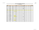
Balancing Tools − Various Options
Terms & Definitions
Defrost Mode (HRV)to ensure reliable operation during
cold weather, the HRV will automatically cycle through its
defrost mode as needed.
Dehumidistata control device that senses the amount
of moisture in the air and activates high−speed ventilation
when the air moisture level exceeds the set point.
Resetwhenever resetting of the HRV/ERV is required,
simply unplug the power cord for 30 seconds. The Self Test
will occur when the HRV/ERV is reconnected.
Self Testeach time the HRV/ERV is powered/energized, the self test function will automatically initiate. During the self test, the HRV/ERV will cycle through all the
speeds available (1 − 5), test the damper motor operation,
and will default back to the previous operational mode and
speed selection. Total self test duration is approximately
90 seconds.
Standby Modethe HRV/ERV is powered/energized and
waiting for fan operation to be initiated. For example, the
HRV is set to Continuous Ventilation Operational Mode at
speed 0.
Thermistorthe HRV/ERV’s temperature sensor which
measures electrical resistance in a known manner, as outdoor temperatures fluctuate.
HVIHome Ventilating Institute.
R2000Canada Home Building Energy Efficiency Standard.
HRAIHeating Refrigeration Air Conditioning Institute.
Application
The Healthy Climate® Heat Recovery Ventilator (HRV)
and Energy Recovery Ventilator (ERV) are designed to
provide fresh air while exhausting an equal amount of stale
air. Refer to application map on page 42.
The HRV unit is equipped with an aluminum core. The device uses the stale air that is being exhausted to condition
the fresh air as it is being brought in.
The ERV unit is equipped with an enthalpic core. This device is designed for use in warm, humid climates with
heavy air conditioning loads. The ERV unit transfers both
sensible (temperature) and latent (moisture) heat from incoming fresh air to the stale air as it is being exhausted;
thus, reducing the air conditioning load. The ERV unit is not
suitable for use in climates where the temperature drops
below 25ºF (−4ºC) for more than 5 days continuously.
Required Tools/Materials
Recommended Materials
low voltage control wire
mastic tape
1/2˜ I.D. drain hose
caulking material
aluminum foil duct tape
zip ties (duct)
fabric flexible duct − class II rated
zip ties
Pitot Tube Balancing Kit (8 ft. vinyl tubing,
Pitot tube, magnehelic gauge [0 − 0.25˜], &
mounting plate) . . . . . . . . . . . . . . . . . . . . . . . . 56N82
Pitot Tube only . . . . . . . . . . . . . . . . . . . . . . . . . 72X52
Digital Manometer with range of 0 - 4.000 in.
w.c. . . . . . . . . . . . . . . . . . . . . . . . . . . . . . . . . . Y6484
Door Port Gauge Tube Set (can be
used to balance HRV3-150-TPD/TPF,
HRV5-150/200 Models Only)
Includes two connection hoses, two rubber
fittings and instructions. Digital manometer
(reading down to 0 with resolution of 0.001 in.
w.c.) or Magnehelic gauge (scale of 0 to 1.0
in. w.c.) is not furnished and must be fields
supplied. . . . . . . . . . . . . . . . . . . . . . . . . . . . Y2207
Optional Accessories
20 Minute Fan Timer . . . . . . . . . . . . . . . . . . . . . . . . . Y2168
20/40/60 Minute Fan Timer . . . . . . . . . . . . . . . . . . . Y2169
Digital Control (wall mounted) . . . . . . . . . . . . . . . . . Y2171
Programmable Control (wall mounted) . . . . . . . . . Y2172
Weatherhood Kit (includes 2 hoods, 2 screens,
2 12" sleeves, 2 collars and supply/exhaust labels):
5˜ (127 mm) . . . . . . . . . . . . . . . . . . . . . . . . . . . . . 92E66
6˜ (152 mm) . . . . . . . . . . . . . . . . . . . . . . . . . . . . . 95P07
7˜ (178 mm) . . . . . . . . . . . . . . . . . . . . . . . . . . . . . 17N11
Round Diffusers:
4˜ (102 mm) . . . . . . . . . . . . . . . . . . . . . . . . . . . . . 92E54
5˜ (127 mm) . . . . . . . . . . . . . . . . . . . . . . . . . . . . . 92E55
6˜ (152 mm) . . . . . . . . . . . . . . . . . . . . . . . . . . . . . 92E56
8˜ (203 mm) . . . . . . . . . . . . . . . . . . . . . . . . . . . . 56N81
Dual Hood kit (includes hood assembly, foam gasket,
duct splitter, duct insulator, retainer screw assembly,
nylon cable tie, screens, labelled Supply/Exhaust.
6" (152 mm) . . . . . . . . . . . . . . . . . . . . . . . . . . . . . . . . Y3813
Kitchen Grille, 6" x 10"(152mm x 254mm)) (May
be required by code for kitchen applications;
contains removable grease filter) . . . . . . . . . . . . . 18N48
Back Draft Dampers:
5" (127 mm) . . . . . . . . . . . . . . . . . . . . . . . . . . . . . Y3728
6" (152 mm) . . . . . . . . . . . . . . . . . . . . . . . . . . . . . Y3727
Butterfly Balancing Dampers:
6˜ (152 mm) . . . . . . . . . . . . . . . . . . . . . . . . . . . . . 91X09
7˜ (178 mm) . . . . . . . . . . . . . . . . . . . . . field supplied
Duct Heaters:
6˜ (152 mm) 1KW . . . . . . . . . . . . . . . . . . . . . . . . 97E73
6˜ (152 mm) 2KW . . . . . . . . . . . . . . . . . . . . . . . 20N16
7˜ (178 mm) 2KW . . . . . . . . . . . . . . . . . . . . . . . . 97E74
Page 2
Dual−Core HRV Units
Single−Core HRV Units
Specifications
HRV3
HRV3
HRV3-150
HRV5
−150−TPD/-150-TPD-GDX −TPF/-150TPF-GDX −095/−095−GDX −150/−150−GDX
(Y2142/Y2967)
(Y5447/Y6423)
(Y6419/Y6420)
(Y5448/Y6424)
Model No.
Single−Core ERV
Units
HRV5
-200-TPD/-200-TPDGDX (Y6421/Y6422)
HRV3−195
(Y2143)
HRV3−300
(Y2144)
ERV3−150
(Y2138)
ERV3−200
(Y2139)
Energy Star® qualified
(Canada Only)
No
No
Yes
Yes
Yes
Yes
Yes
No
No
Cabinet Size (Inches)
14 x 17−1/4 x
22−3/4
14 x 17−1/4 x
22−3/4
16 x 24-1/2 x
18-1/2
14-3/4 x 19 x
33-5/8
15 x 18-3/4 x
33-5/8
14-3/4 x 19
x 49
14-3/4 x 19
x 49
14-3/4 x 19
x 33-5/8
14-3/4 x 19
x 33-5/8
Weight
51
51
52
71
57
106
106
75
75
Shipping Weight
54
54
56
73
67
108
108
77
77
High Speed (HVI Certified)
in. w.g. (Pa)
CFM (L/s)
CFM (L/s)
CFM (L/s)
CFM (L/s)
CFM (L/s)
CFM (L/s)
CFM (L/s)
CFM (L/s)
CFM (L/s)
0.1 (25)
169 (74)
174 (82)
76 (36)
184 (87)
222 (105)
216 (101)
232 (110)
151 (71)
180 (85)
0.2 (50)
156 (69)
165 (77)
73 (34)
163 (77)
207 (98)
195 (92)
212 (100)
141 (67)
169 (79)
0.3 (75)
149 (63)
154 (73)
70 (33)
146 (69)
193 (91)
181 (85)
202 (95)
132 (62)
157 (74)
0.4 (100)
136 (59)
143 (67)
66 (31)
132 (62)
179 (84)
158 (74)
183 (86)
124 (59)
146 (69)
0.5 (125)
126 (54)
132 (62)
60 (28)
115 (54)
165 (78)
144 (68)
163 (77)
107 (50)
132 (62)
0.6 (150)
116 (49)
120 (56)
92 (43)
150 (71)
125 (59)
144 (68)
98 (46)
118 (55)
0.7 (175)
103 (45)
107 (521)
60 (28)
135 (63)
107 (50)
123 (58)
81 (38)
101 (47)
72 (34)
92 (43)
60 (28)
82 (39)
0.8 (200)
89 (40)
95 (45)
119 (56)
0.9 (225)
77 (33)
83 (39)
102 (49)
58 (29)
71 (34)
Sensible Effectiveness
@ 32ºF (0ºC)
@ 66 CFM
(31 L/s) 74%
@ 66 CFM
(31 L/s) 75%
@ 60 CFM (28
L/s) 88%
@ 59 CFM (28
L/s) 84%
@ 100 CFM
(47 L/s) 77%
@ 114 CFM
(54 L/s) 86%
@ 117 CFM
(55 L/s) 90%
@ 63 CFM
(30 L/s) 81%
@ 116 CFM
(55 L/s) 76%
Sensible Efficiency
@ 32ºF (0ºC)
@ 66 CFM
(31 L/s) 61%
@ 66 CFM
(31 L/s) 66%
@ 60 CFM (28
L/s) 75%
@ 59 CFM (28
L/s) 75%
@ 100 CFM
(47 L/s) 68%
@ 114 CFM
(54 L/s) 78%
@ 117 CFM
(55 L/s) 79%
@ 63 CFM
(30 L/s) 69%
@ 116 CFM
(55 L/s) 69%
Sensible Efficiency
@ −13ºF (−25ºC)
@ 76 CFM
(31 L/s) 63%
@ 76 CFM
(30 L/s) 56%
@ 61 CFM (29
L/s) 68%
@ 64 CFM (30
L/s) 72%
@ 100 CFM
(47 L/s) 68%
@ 112 CFM
(53 L/s) 72%
@ 132 CFM
(62 L/s) 70%
N/A
N/A
Latent Efficiency
95ºF (35ºC)
N/A
N/A
N/A
N/A
N/A
N/A
N/A
@ 65 CFM
(30 L/s) 37%
@ 117 CFM
(55 L/s) 41%
Total Efficiency
95ºF (35ºC)
N/A
N/A
N/A
N/A
N/A
N/A
N/A
@ 65 CFM
(30 L/s) 47%
@ 117 CFM
(55 L/s) 50%
2
2
2
2
2
2
2
1
1
5
5
5
5
5
5
5
5
5
Heat Recovery
Heat
Recovery
Heat
Recovery
Energy
Recovery
Energy
Recovery
Enthalpic
1.0 (250)
Number of speeds available
with included wall control
Number of speeds available
with optional wall control
84 (40)
Ventilator Type
Heat
Recovery
Heat
Recovery
Heat/Energy Recovery Core
Aluminum
Aluminum
Aluminum
Aluminum
Aluminum
Aluminum
Aluminum
Enthalpic
Number of HRV/ERV Cores
1
1
1
1
1
2
2
1
1
Recirculating
Fan
Recirculating
Recirculating
Damper
Damper
None
None
Door Port Balancing
Yes
Yes
No
Yes
Yes
No
No
No
No
Balancing Damper in
Supply & Exhaust Collar
Yes
Yes
No
Yes
Yes
No
No
Yes
Yes
Defrost Type
Heat Recovery Heat Recovery
Recirculating
4
4
4
4
4
5
5
4
4
Yes
Yes
Yes
Yes
Yes
Yes
Yes
Yes
Yes
Y2166
Y2166/Y2171
Y2166/Y2171
Y2166/Y2171
Y2166
Y2166
N/A
N/A
N/A
N/A
N/A
N/A
N/A
N/A
N/A
Yes
Yes
Fan HP
1/20
1/20
1/20
1/10
1/10
1/10
1/4
1/20
1/10
Motor Type
PSC
PSC
PSC
PSC
PSC
PSC
PSC
PSC
PSC
Fan Watts − High Speed
@ 0.3 in. w.g.
110
118
150
118
96
173
333
173
182
Fan Watts − Low Speed
@ 0.3 in. w.g.
57
66
60
66
64
100
150
63
70
Amp Rating
1.3
1.4
0.9
1.4
1.4
1.5
2.9
1.4
1.4
Condensate Drain
Connections:
Spouts: qty. 2 (1/2" o.d.)
Drain Tee: qty. 1 (1/2" o.d.)
Yes
Yes
Yes
Yes
Yes
Yes
Yes
N/A
N/A
Number of Ports
Pre-Filters (Foam) Supply &
Exhaust
Wall Controller Included
H/C ERV Wall Control−
on/off, Service Indicator
(Y2165)
Y2166/Y2171
Electrical Characteristics
120 Volts, 60 Hertz, 1 phase
table continued on next page
NOTE: All specifications are subject to change without notice.
Page 3
Healthy Climate® HRV/ERV Ventilators
Model No.
Dual−Core HRV Units
Single−Core HRV Units
Specifications
HRV3-150
HRV3
-150-TPD/-150-TPD-GDX −TPF/-150-TPF-GDX
(Y5448/Y6424)
(Y5447/Y6423)
HRV5
HRV3
HRV5
−095/−095−GDX −150/−150−GDX -200−TPD/-200−TPD−GDX
(Y2142/Y2967) (Y6419/Y6420)
(Y6421/Y6422)
HRV3−195
(Y2143)
HRV3−300
(Y2144)
Single−Core ERV
Units
ERV3−150
(Y2138)
ERV3−200
(Y2139)
OPTIONAL FAN CURVES SPEEDS (FACTORY TESTED)
Speed 4−med high
in. w.g. (Pa)
CFM (L/s)
CFM (L/s)
CFM (L/s)
CFM (L/s)
CFM (L/s)
CFM (L/s)
CFM (L/s)
0.1 (25)
CFM (L/s)
70 (33)
153 (72)
189 (89)
167 (78)
220 (103)
120 (56)
151 (71)
0.2 (50)
65 (31)
141 (67)
170 (80)
159 (75)
202 (94)
111 (52)
147 (69)
0.3 (75)
50 (24)
131 (62)
153 (72)
150 (71)
186 (87)
103 (48)
129 (61)
31 (15)
117 (55)
136 (64)
140 (66)
169 (79)
92 (43)
118 (55)
120 (57)
124 (58)
158 (74)
80 (38)
104 (49)
CFM (L/s)
0.4 (100)
101 (48)
101 (48)
0.5 (125)
91 (43)
91 (43)
96 (45)
0.6 (150)
82 (39)
82 (39)
80 (38)
106 (50)
110 (52)
134 (62)
64 (30)
89 (42)
0.7 (175)
69 (33)
69 (33)
91 (43)
93 (44)
108 (50)
43 (20)
63 (30)
0.8 (200)
60 (28)
60 (28)
78 (37)
79 (37)
Speed 3−med
0.1 (25)
65 (31)
0.2 (50)
60 (28)
0.3 (75)
92 (43)
92 (43)
48 (23)
0.4 (100)
82 (39)
82 (39)
30 (14)
0.5 (125)
71 (34)
71 (34)
0.6 (150)
60 (28)
60 (28)
144 (68)
161 (76)
142 (67)
194 (91)
97 (46)
133 (63)
130 (61)
141 (67)
136 (64)
178 (83)
87 (41)
130 (61)
120 (57)
123 (58)
127 (60)
170 (79)
81 (38)
124 (58)
106 (50)
108 (51)
118 (55)
154 (72)
72 (34)
114 (54)
88 (42)
92 (43)
103 (48)
139 (65)
61 (29)
104 (49)
53 (25)
94 (44)
77 (36)
92 (43)
118 (55)
0.7 (175)
64 (30)
72 (34)
94 (44)
0.8 (200)
52 (25)
80 (38)
Speed 2−med low
127 (60)
127 (60)
115 (54)
170 (79)
73 (34)
112 (53)
0.2 (50)
81 (38)
81 (38)
54 (25)
116 (55)
108 (51)
107 (50)
163 (76)
67 (31)
107 (50)
0.1 (25)
62 (29)
0.3 (75)
70 (33)
70 (33)
42 (20)
106 (50)
90 (42)
100 (47)
151 (70)
59 (28)
101 (47)
0.4 (100)
60 (28)
60 (28)
26 (12)
97 (46)
73 (34)
90 (42)
136 (63)
51 (24)
96 (45)
0.5 (125)
46 (22)
46 (22)
86 (40)
60 (28)
81 (38)
129 (60)
45 (21)
88 (41)
0.6 (150)
48 (22)
66 (31)
107 (50)
77 (36)
0.7 (175)
38 (18)
88 (41)
60 (28)
0.8 (200)
Speed 1−low
108 (51)
100 (48)
88 (41)
144 (67)
53 (25)
88 (41)
0.2 (50)
61 (29)
61 (29)
45 (21)
100 (47)
78 (37)
80 (38)
137 (64)
44 (21)
85 (40)
0.3 (75)
49 (23)
49 (23)
33 (16)
91 (43)
60 (28)
73 (34)
134 (62)
38 (18)
80 (38)
0.4 (100)
35 (17)
35 (17)
18 (8)
78 (37)
46 (22)
63 (30)
121 (56)
32 (15)
77 (36)
32 (15)
56 (26)
110 (51)
43 (20)
95 (44)
0.1 (25)
51 (24)
0.5 (125)
0.6 (150)
0.7 (175)
67 (31)
84 (39)
0.8 (200)
OPTIONAL ACCESSORIES−MUST BE ORDERED EXTRA
Backdraft Damper 5"
Y3728
Y3728
Y3728
N/A
N/A
N/A
N/A
N/A
N/A
Backdraft Damper 6"
N/A
N/A
N/A
Y3727
Y3727
Y3727
Y3727
Y3727
Y3727
Butterfly Damper, 6"
N/A
N/A
91X09
Included in the unit
N/A
N/A
N/A
Butterfly Damper, 7"
N/A
N/A
N/A
N/A
N/A
(2) 5
(2) 5
(2) 5
(2) 6
(2) 6
Insulated Flexible Ducting:
(Qty Req’d) Dia.
Field Supplied
(2) 6
COMMON ACCESSORIES − AS REQUIRED, BASED ON USER APPLICATION
Door Port Balancing Kit
N/A
Y2206
N/A
(same kit w/o Gauge)
Y2207
Digital Handheld
Manometer
Y6484
Magnehelic Gauge only
(0-0.25")
N/A
N/A
Pitot Tube Balancing Kit
N/A
N/A
79P83
56N82
72X52
Pitot Tube only
NOTE: All specifications are subject to change without notice.
Page 4
(2) 6
Included in the unit
N/A
N/A
(2) 6
(2) 6
Ventilator Dimensions and Flow Diagrams
Filter
Balancing
Damper
Blower
ERV3-150/200
Blancing Damper
Removable
Core
19 in (483 mm)
Fresh
Air To
Inside
Motor
Stale
Air From
Inside
Blower
Fresh
Air From
Outside
Stale
Air To
Outside
33 5/8 in (850 mm)
Front View
14 3/4 in (375 mm)
Note: Front clearance of 25 in (635 mm) is recommended for servicing unit.
All ducts use 6 in (152 mm) connections.
Fresh Air
From Outside
Recirculating
Defrost
Damper
Filter
Side View
HRV5-150
Stale Air
From Inside
14 3/4 in (375 mm)
Blower
Stale
Air To
Outside
Fresh
Air To
Inside
Motor
18 3/4 in (476 mm)
Removable
Heat
Recovery
Core
Note: Front
clearance of 25 in
(635 mm) is
recommended for
servicing unit. All
ducts use 6 in (152
mm) connections.
33 5/8 in (854 mm)
Condensate Drain
Removable
Heat
Recovery
Core
Side View
Front View
HRV3-195/300
Metal Clasps
Filter
Motor
Stale
Air From
Inside
Fresh
Air From
Outside
Fresh
Air To
Inside
Defrost
Damper
Blower
49 in (1245 mm)
Defrost Air
From Inside
Front View
Note: Front
clearance of 25 in
(635 mm) is
recommended for
servicing unit..
Outside ports, 6 in
(150 mm). Inside
ports, 7 in
(178 mm)
18 3/4 in (476 mm)
Stale
Air To
Outside
14 3/4 in (375 mm)
Condensate Drains
Page 5
Side View
Healthy Climate® HRV/ERV Ventilators
HRV3-150-TPD/TPF
Stale
Fresh
Fresh
Stale
Air To Air From Air From Air To
Outside Outside Inside Inside
Filter
Removable
Heat Recovery
Core
Motorized
Impeller
14 in (356 mm)
17 1/4 in (438 mm)
Recirculating
Defrost Damper
(For TPD
Model Only)
Note: Front clearance of 25 in (635 mm) is
recommended for servicing unit. All ducts
use 5 in (125 mm) oval collars, balancing
dampers are located on all collars.
22 3/4 in (578 mm)
Top View
Front View
HRV5-200-TPD
Fresh
Stale
Air From Air To
Inside Inside
Stale
Fresh
Air To Air From
Outside Outside
Note: Front clearance of 25 in (635 mm) is
recommended for servicing unit. All ducts
use 6 in (150 mm) oval collars, balancing
dampers are located on all collars.
Filter
18 3/4 in (476 mm)
Recirculating
Defrost
Damper
Removable
Heat Recovery
Core
Motorized
Impeller
15 in (381 mm)
Condensate Drains
33 5/8 in (854 mm)
Condensate Drain
FRESH
STALE
AIR FROM AIR TO
FRESH OUTSIDE OUTSIDE
AIR TO
A
INSIDE B
D
C
FILTER
(in back
chamber)
Top View
Front View
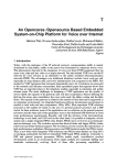
HRV3-095
ADJUSTABLE HANGING
STRAPS WITH S HOOK (4)
THREADED INSERTS
(4) at corners
STALE AIR
FROM INSIDE
D
B
C
A
FRESH AIR
FROM
OUTSIDE
(Supply) 5"
(127 mm)
round collar
DIVIDER PANEL
(each side)
CORE
18−1/2" (470 mm)
DRAIN
PAN
DRAIN
SPOUT
24−1/2"
(622 mm)
FILTER
(in front
chamber)
18 inches (457
mm) (min.) required
for service access
FRESH AIR
TO INSIDE
(Supply) 6"
(178 mm)
round
(converted to
oval collar)
TOP VIEW
18−1/2"
(470 mm)
A
STALE AIR TO
OUTSIDE
(Exhaust) 5" (127
mm) round collar
D
C
B
STALE AIR
FROM INSIDE
(Exhaust)
6" (178 mm)
round (converted
to oval) collar
supplied
16"
(406 mm)
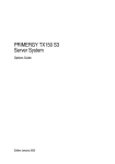
HRV3−095 Air Flow Direction
The top half of the unit is divided front to back. This unique configuration allows the air to actually travel through the core
twice, making the HRV3−095 unit almost as efficient as a double core unit.
Stale air enters the front right side port. The air will pass down the front half of the core, then up the back half of the core
and out the right rear port. Fresh outdoor air will enter the left rear port and pass down the back half of the core. It will then
pass up the front half of the core, and out the left front port.
Page 6
Healthy Climate® HRV/ERV Ventilators
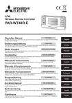
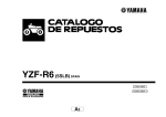
Damper Defrost − 5 port Models (HRV3−195/300)
Defrost Cycle (HRV)
The HRV has an electronically controlled defrost system.
The defrost cycle is activated when the outdoor temperature drops below 27ºF (−3ºC). There are three levels of defrost mode based on the outdoor temperature. Incoming
fresh air is measured to set the defrost times and the run
times while in the defrost mode. The three defrost settings
are:
S At 27ºF (−3ºC) HRV runs in defrost for 3 minutes and
runs in ventilation for 25 minutes
S At −4ºF (−20ºC) HRV runs in defrost for 4.5 minutes and
runs in ventilation for 17 minutes
S At −31ºF (−35ºC) HRV runs in defrost for 7 minutes and
runs in ventilation for 15 minutes
No remote device can override this defrost mode or selected speed until the cycle is complete. After the cycle is
completed the HRV defaults to previous settings. If the
cycle is completed and the thermistor continues to measure defrost temperature the defrost cycle is repeated.
ERV’s have no defrost cycle and are not recommended
where outdoor temperatures fall below 25ºF (−4ºC) continuously for more than 5 days.
Recirculating Damper Defrost (HRV3−095,
HRV3−150−TPD, HRV5−150, HRV5-200-TPD)
During defrost a motor driven damper door mechanism
closes off the supply air from outside allowing exhaust air
to recirculate through the unit’s core. During defrost cycle
no ventilation is occurring. After the defrost period, the
damper operates in the opposite direction to reopen the
fresh air port. Defrost cycle repeats until the temperature
rises above 27ºF (−3ºC).
Page 7
During defrost a motor driven damper door mechanism
closes off the supply air from outside allowing a fifth port to
open enabling warm air to be drawn in from around the
unit. During defrost cycle stale air exhaust is still occurring.
After the defrost period, the damper operates in the opposite direction to reopen the fresh air port. Defrost cycle repeats until the temperature rises above 27ºF (−3ºC). (The
defrost port can also be ducted to another location.)
Fan Defrost (HRV3−150−TPF)
During defrost cycle, the Fresh Air supply motor will shut
off and the Stale Air exhaust motor will continue to run.
After the defrost period, the Fresh Air supply motor will resume. Defrost cycle repeats until the temperature rises
above 27ºF (−3ºC).
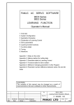
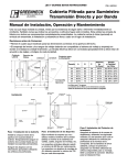
6" Diameter
SAME CIRCUMFERENCE
In order to make the HRV3−095 unit as space efficient as possible, the
indoor supply and return ports are converted from round to oval
shape. Circumference of the port remains the same. Simply bend a
standard duct fitting to the correct shape, and attach to the oval port
using the same method as for a round port.
Figure 1. Shaping Ducting to fit Oval Indoor
Supply Port
Requirements
Connecting appliances to the HRV/ERV unit
The following appliances should not be connected to the HRV/ERV unit:
S clothes dryer
S range top
S stove top fan
S central vacuum system
NOTE − Failure to follow this instruction will void the HRV/ERV unit warranty.
DANGER
Risk of Carbon Monoxide Poisoning and/or Explosion.
Can cause injury or death.
Combustion and flue gases from heating appliances must never be allowed to enter living spaces.
HRV/ERV unit must be properly balanced (see page 28 or 31) to prevent negative pressure in structure. Negative
pressure can cause back−drafting of combustion gases in other household appliances such as Gas Furnaces,
Oil Furnaces, Hot Water Heaters, Wood Stoves, Fireplaces, etc.
(5-Port HRV models only) Defrost cycles will cause negative pressure in equipment room. Install ductwork and
route to areas that do not contain appliances with vented combusted gases.
Never connect a return or supply duct to other heating units such as fireplaces, wood stoves.
CAUTION
Potential equipment malfunction or damage.
May require repairs and/or void warranty.
Do not interconnect HRV/ERV to other appliances such as Stove Vents, Clothes Dryer Vents, Central Vacuum
Systems, Auxiliary Fans, etc.
Page 8
Healthy Climate® HRV/ERV Ventilators
Controlling the HRV/ERV
Today’s modern, air tight homes require fresh outdoor air
to maintain a healthy indoor air environment. The amount
of ventilation required in a home depends upon:
S the number of occupants and their activity levels.
S the way the home was built,
S personal preferences for fresh air.
The HRV/ERV introduces fresh air to your home while recovering energy from the air it exhausts. Specifically, an
HRV/ERV that is properly installed, operated, and maintained will:
S exhaust stale, contaminated air,
S recover the majority of the energy from the exhausted
stale air,
S use the recovered energy to preheat or precool outside air that is drawn into the house,
S distribute the fresh air throughout the house.
HRV controls include a dehumidistat function which can be
set to achieve a dehumidification effect from the HRV during the winter heating season. High-speed ventilation will
be initiated upon exceeding the dehumidistat set point.
Once the humidity in the house is reduced, the HRV will revert back to its previous setting.
How much ventilation is needed?
Synchronizing the Humidity Setting
During seasons when windows and doors are closed (winter and summer, if air conditioned) the HRV/ERV should be
set to operate continuously on low speed with the option of
going to high speed as the need arises. For example, if a
large number of people are present in the home, the unit
should be switched temporarily to high speed. Conversely,
when the home is unoccupied, an intermittent operational
mode (e.g. 20 minutes on / 40 minutes off) may be used.
The optional wall controls (Y2171 and Y2172) have a feature that allows the controls to be synchronized with other
humidity instruments in the home. To synchronize:
1. Turn off the control with the ON/OFF button.
2. Simultaneously press and release the ON/OFF button
and the 20/40/60 minute high−speed override button.
3. Use the Up/Down arrow buttons to adjust the Humidity
Indicator on the display screen to the number of degrees difference between your humidity measuring
device. Minus is indicated by flashing.
4. Press the MODE button.
Electronics
All units include a Wall Control. Optional controls can be
installed at the time of the installation or at a later date, providing a number of choices for upgrading the basic features of the ventilation system.
Dehumidistat Operation
Often, well insulated and air tight homes will have high indoor humidity levels during the heating season. High humidity levels are apparent from the visible condensation on
windows. The amount of condensation on the windows will
increase as outdoor temperatures drop.
The HRV/ERV will reduce indoor humidity levels when outdoor air is drier than indoor air. This usually occurs during
the heating season when outdoor temperatures are less
than 59ºF (15ºC).
It is recommended that the unit be operated for the first few
days without use of the dehumidistat function to observe if
a further dehumidification effect will be required. The dehumidistat operates in % of RH (relative humidity) with 80 being high and 20 being low. Set the Dehumidistat to 80% RH
to disable. If, after a few days, further dehumidification is
required (the house is too humid), set the humidity level to
a lower setting. Comfortable humidity levels range between 30 and 50% RH, depending on personal preference.
The dehumidistat should be off for all seasons except the
heating season (set to 80% RH).
Dehumidistat Disable Feature
The new auto dehumidistat function prevents unwanted
use of the dehumidistat when outdoor temperature exceeds 59ºF (15ºC).
The dehumidistat function will be disabled if the outdoor
temperature exceeds 59ºF (15ºC) for a 24−hour period.
The dehumidistat function will be re-enabled if the unit is
unplugged for 3 minutes or if the outdoor temperature
drops below 59ºF (15ºC) for a 24-hour period. The dehumidistat disable feature is permanently enabled in the ERV
unit.
Page 9
Ventilation Controls (included)
ERV Ventilation Control (Y2165)
Home ventilation provided by the ERV unit is easily controlled with included ERV Ventilation System control.
Key features
S
ON/OFF button with ON LED
S
Service indicator
S
Connect to 3−wire, 20−gauge (min.), low−voltage wire.
Service Indicator LEDAfter 4 months, a SERVICE" indicator will appear. Refer to Homeowner Maintenance Information, page 41. Upon completion of maintenance, reset service light by pressing and holding RESET button for
5 seconds.
Instruction Card
UNIT ON/OFF ControlPress and release the ON/OFF
button. ON" indicator light illuminates; press again to turn
OFF.
Service Indicator LEDAfter 4 months, a SERVICE" indicator will appear. Refer to Homeowner Maintenance Information, page 41. Upon completion of maintenance, reset service light by pressing and holding RESET button for
5 seconds.
ON LED
Service
Indicator LED
ON/OFF
Button
Service Reset
Button
HRV Ventilation Control (Y2166)**
Home ventilation provided by the HRV unit is easily controlled with included HRV Ventilation System control.
**HRV −GDX (Canada only) units come with Y2171 Digital
2−Speed/4−Mode Control (see figure 4, Page 10).
Key features
Figure 2. ERV Control (Y2165)
S
ON/OFF button with ON LED
S
Dehumidistat with LED indications
S
Service indicator
S
Connect to 3−wire, 20−gauge (min.), low−voltage wire.
Instruction Card
UNIT ON/OFF ControlPress and release the ON/OFF
button. ON" indicator light illuminates; press again to turn
OFF.
Humidity ControlUnit will produce a dehumidifying effect when outdoor humidity levels are lower than indoor
humidity levels. Dehumidistat should not be used when
outdoor temperatures are above 59ºF (15ºC). Press and
release DEHUMIDISTAT button until the DEHUMIDISTAT
LED is at the desired setting. After seconds, the dehumidistat light will either flash or be on continuously. A flashing
light indicates the humidity level is higher than the setting
and the unit is operating on high−speed ventilation. A continuous light indicates the humidity level is lower than the
setting.
NOTE − Only 1 dehumidistat should be active on a system.
Page 10
Dehumidistat
Indicator LEDs
ON LED
Service
Indicator LED
ON/OFF
Button
Service Reset
Button
Figure 3. HRV Control (Y2166)
Healthy Climate® HRV/ERV Ventilators
Ventilation Controls (optional)
* NOTE: Recirculation is available on HRV3−095, HRV5−150,
HRV5-200-TPD only.
4-Mode Descriptions
The two optional digital controls have 4 operational modes
and 2 or 5 speeds on each mode to adjust indoor ventilation levels. Experiment with the ventilation levels in the
home to evaluate the best amount of ventilation to suit the
homeowner needs and preferences.
1. Continuous Ventilation Mode (VENT)
This is the most popular mode since it provides continuous ventilation within the home. You may, for example, select Continuous Ventilation at high speed for
high household activity levels, or Continuous Ventilation at low speed for lower activity levels.
2. 20 minutes ON, 40 minutes OFF Mode (20/40)
This mode provides 20 minutes of ventilation each
hour. Use this mode in low speed for low household activity levels or if the home is unoccupied.
3. 20 minutes ON, 40 minutes, Recirculation Mode*
(20/40/RECIRC)
This mode provides 20 minutes of ventilation each
hour and 40 minutes of recirculated air. Use this mode
if the HRV is NOT connected to a forced air system
(forced air system already circulates household air).
4. Continuous Recirculation Mode* (RECIRC)
This mode recirculates household air (no ventilation).
Use this mode if the HRV is NOT connected to a forced
air system.
Synchronizing the Humidity Setting on Digital
Controls
S
S
S
Standby setting (Fan speed 0)
Electronic dehumidistat
Four selectable modes of operation (see 4−Mode Descriptions" in left column of this page)
Continuous Ventilation (VENT)
20 min. On / 40 min. Off (20/40)
20 min. On / 40 min. Recirculate* (20/40/RECIRC)
Continuous Recirculation* (RECIRC)
S 20 / 40 / 60 High speed override button
S Instruction card inserted in control
S Easy-to-read LCD screen
S Connect to 3−wire, 20−gauge (min.), low−voltage wire
Setting the Control
1. Press and release MODE until FAN symbol appears
on the screen. Press SET.
2. Use UP/DOWN arrows to select desired fan speed (0,
1, 2). Press SET.
3. Use UP/DOWN arrows to select the desired operational mode (VENT, 20/40, 20/40 RECIRC*, RECIRC*, OFF). Press SET.
20/40/60 Minute High Speed Timer OverrideThis
function temporarily initiates high−speed ventilation for 20,
40, or 60 minutes. Press OVERRIDE once for 20, twice for
40, and three times for 60 minutes.
Setting DehumidistatRefer to Dehumidistat Operation" (Page 8) before setting the dehumidistat.
1. Press and release MODE until RH" and a number
flashes. Use UP/DOWN arrows to select desired number. Press MODE to exit.
2. Press MODE again to return to operational features.
Either optional control has a feature that allows it to be synchronized with other humidity instruments in the home. To
synchronize:
1. Turn off the control by pressing ON/OFF.
2. Simultaneously press and release ON/OFF and the
20/40/60 minute high−speed OVERRIDE buttons.
3. Use the UP/DOWN arrows to adjust the Humidity Indicator on the display screen to the number of degrees
difference between your humidity measuring device.
Minus is indicated by flashing.
4. Press MODE.
Digital 2−Speed/4−Mode Control (Y2171)
This fully-digital device allows control of when and how
much fresh air will enter the home.
Key features
S 2−speed fan setting (Low−1/High−2)
Page 11
Fan speed
indicator
20/40/60 minute
high−speed
OVERRIDE
button
MODE
select button
Instruction
card
Humidity
indicator
Increase
button (UP
arrow)
Mode indicator
ON/OFF button
High speed
override timer
indicator
SET button
Decrease
button
(DOWN
arrow)
Figure 4. Digital 2-Speed/4-Mode Control
(Y2171)
Ventilation Controls (optional) − continued
* NOTE: Recirculation is available on HRV3−095,
HRV5−150, HRV5-200-TPD only.
Programmable 5-Speed/4-Mode Control (Y2172)
The optional Programmable 5-Speed/4-Mode Control is
fully digital and allows programming that determines when,
and how much, fresh air will be entering the home.
Key features
S 24/7 programmable ventilation
S 4 programmable events per day
S 5-speed fan setting
S Electronic dehumidistat
S Four selectable modes of operation (see 4−Mode Descriptions" on page 10)
Continuous Ventilation (VENT)
20 min. On / 40 min. Off (20/40)
20 min. On / 40 min. Recirculate* (20/40/RECIRC)
Continuous Recirculation* (RECIRC)
S 20 / 40 / 60 High speed override button
S Service/Maintenance reminder display
S Easy-to-read, backlit LCD screen
S Connect to 3−wire, 20−gauge (min.), low−voltage wire
Setting Date & Time
1. Press and release MODE until TIME" and SET" appear on the screen. Press SET.
2. The day of the week letter flashes. Use UP/DOWN arrows to find the correct day of the week. Press SET.
3. The hour and AM" or PM" flashes. Use UP/DOWN
arrows to find the correct hour. Press SET.
4. The minutes will flash. Use UP/DOWN arrows to find
the correct minute. Press SET to complete entry.
Programming the Control
1. Press and release MODE until PROGRAM SET" appears. Press SET.
2. Weekday letters (MTWTF) flash. Press SET.
3. WAKE" flashes. Press SET.
4. AM" or PM" flashes. Use UP/DOWN arrows to find
desired time (in 20 minute intervals). Press SET.
5. FAN" flashes. Use UP/DOWN arrows to find desired
fan speed (0 − 5). Press SET.
6. OFF" flashes. Use UP/DOWN arrows to find desired
operation mode (VENT, 20/40, 20/40/RECIRC*. RECIRC*, OFF). Press SET button two times. (Refer to
4−Mode Descriptions" [Page 10] for a description of
operational modes.)
7. LEAVE" flashes. Repeat steps 4 to 6 to program up
to 4 events per day.
8. ARRIVE" flashes. Repeat steps 4 to 6 to program up
to 4 events per day.
9. SLEEP" flashes. Repeat steps 4 to 6 to program up
to 4 events per day.
10. Weekend" letters (SS) flash. Press SET. Repeat step
3 to 9.
Running the Programmed SettingAfter the programming has been completed, activate the program:
S Press the MODE button until PROGRAM" and RUN"
are indicated.
Setting the DehumidistatSee Dehumidistat Operation" (Page 8) before setting the dehumidistat.
1. Press and release MODE until RH" and a number
flashes. Use UP/DOWN arrows to find the desired
number (RH set point). Press the MODE button to exit.
2. Press MODE again to return to operational features.
IMPORTANT
Only one main control can be installed on the system.
Manually Setting the Control
1. Press and release MODE until MANUAL" and RUN"
flashes. Press SET.
2. Use UP/DOWN arrows to select the desired fan speed
(0 − 5) using the UP/DOWN arrows. Press SET.
3. Use UP/DOWN arrows to select the desired operation
mode (VENT, 20/40, 20/40 RECIRC*. RECIRC*,
OFF) using the UP/DOWN arrows. Press SET.
4. The control will remain in the MANUAL RUN" position
until you change back to PROGRAM RUN" (refer to
Running the Programmed Setting" above).
20/40/60 Minute high−speed Override ButtonThis
function temporarily initiates high−speed ventilation for 20,
40, or 60 minutes. Press OVERRIDE once for 20, twice for
40, and three times for 60 minutes.
Service IndicatorAfter 4 months, a SERVICE" indicator will appear. To reset the service indicator:
S Press and release the UP/DOWN arrows simultaneously. SERVICE" icons will flash for 5 seconds.
S Press SET within the 5 seconds and the service indicator will reset.
Page 12
Fan speed
indicator
20/40/60 minute
high−speed
OVERRIDE
button
MODE select
button
Mode indicator
ON/OFF button
High−speed
override timer
indicator
Instruction
card
Date and time
Humidity
indicator
Increase
button (UP
arrow)
SET button
Decrease
button (DOWN
arrow)
Service
indicator
Daytime event
program
indicator
Figure 5. Programmable 5-Speed/4-Mode
Control (Y2172)
Healthy Climate® HRV/ERV Ventilators
Optional Timers
The timer will override the Operational Mode (regardless of the setting) and initiate high-speed ventilation. Upon completion
of the timer cycle, the HRV/ERV will return to preselected operational mode and speed setting.
20 Minute Timer (Y2168)
20/40/60 Minute Timer (Y2169)
Initiates high-speed ventilation for 20 minutes. The 20 minute status light indicate high−speed operation.
Initiates high-speed ventilation for 20, 40, or 60 minutes.
The 20/40/60 minute status lights indicate high−speed operation.
Lockout Mode is useful to disable the timer. Set lockout by
holding the SELECT button for 5 seconds; similarly, unlock
by holding the SELECT button for 5 seconds.
Connect to 3-wire, 20-gauge (min.) low-voltage wire and is
installed in a standard 2" x 4" electrical box.
Lockout Mode is useful to disable the timer. Set lockout by
holding the SELECT button for 5 seconds; similarly, unlock
by holding the SELECT button for 5 seconds.
Connect to 3-wire, 20-gauge low-voltage wire and is
installed in a standard 2" x 4" electrical box.
20/40/60 Minute
Status Lights
20 Minute
Status Lights
Select Button
Select Button
Figure 6. 20 Minute Timer (Y2168)
Figure 7. 20/40/60 Minute Timer (Y2169)
Page 13
Installation Methods
There are three methods of installation for the HRV/ERV:
S Simplified installation (Page 14)
S Partially dedicated installation (Page 15)
S Fully dedicated installation (Page 16)
Sizing the Ductwork
The installer must ensure all ductwork is sized and
installed as designed to ensure the system will perform as
intended.
The amount of air (cfm) that the HRV/ERV unit will deliver
is directly related to the total external static pressure
(E.S.P.) of the system. Static pressure is a measure of resistance imposed on the blower by length of ductwork plus
the number of fittings used in the ductwork.
Installing Ducting Between the HRV/ERV Unit
and Living Areas in the House
All duct joints must be fastened with screws, rivets or duct
sealant and wrapped with mastic or quality duct tape to
prevent leakage. Mastic is preferred but if duct tape is used
it should be the aluminum foil type.
Galvanized (rigid) ducting from the HRV/ERV to the living
areas in the house is recommended whenever possible although flexible duct can be used in moderation, if necessary.
A short length (approximately 12" [300mm]) of non-metallic flexible insulated duct should be connected between the
HRV/ERV and the supply/exhaust duct system to avoid
possible noise transfer through the duct system.
All ducts running through attics and unheated spaces must
be sealed and insulated to code.
A well designed and installed ducting system will allow the
HRV/ERV to operate at its maximum efficiency.
All ducts should be kept short and have as few bends or
elbows as possible to maximize airflow. Forty-five degree
elbows are preferred to 90º elbows. Use Y" tees instead of
straight tees whenever possible.
Page 14
IMPORTANT
Applications such as greenhouses, atriums, swimming pools, saunas, etc. have unique ventilation requirements which should be addressed with an isolated ventilation system.
Healthy Climate® HRV/ERV Ventilators
Installation MethodsSimplified (Return/Return)
Simplified Installation (Return/Return Method)
The simplified method draws stale air from the cold air return duct of the air handler/furnace and introduces an
equal amount of fresh air farther downstream into the cold
air return (see figures 8 and 9).
Key points
S
The HRV/ERV unit must be balanced.
S
It is mandatory (to eliminate recirculation) that either
the furnace blower run continuously or HRV/ERV unit
operation be interlocked with the furnace blower.
S
The duct configuration may change depending on the
HRV/ERV model. See specifications for your unit.
S
Check local codes and authority having jurisdiction for
acceptance.
Return
Air
Figure 8. Simplified Installation (Return/Return)
Return Air
40" (1 m)
Minimum
Dampers for
Balancing
Airflows
Outdoors
36"
(914mm) Min.
Recommended
Cool Air
Return
Spring−Loaded
Backdraft
Damper
(Recommended)
Leaf Hinge (Recommended)
Install the Backdraft Damper with the leaf hinge vertical.
The damper is installed on the Stale Air to Outside Collar".
5" (127 mm) Backdraft Damper (Y3728)
6" (152 mm) Backdraft Damper (Y3727)
Forced Air
Furnace
Installation Notes
S See unit specifications for exact port locations.
S Unit is normally balanced on HIGH speed with the furnace blower ON.
S A minimum separation of 40 inches (1m) is recommended between the two direct connections.
S The exhaust air connection should be upstream of the supply air connection to prevent exhausting any fresh air.
S Weatherhood arrangement is for drawing purposes only. Six feet (2m) minimum separation is recommended. The
weatherhood must be 18" (460mm) above grade minimum.
S The airflow must be confirmed on site using the balancing procedures found in this manual.
Figure 9. Direct Connection of both HRV/ERV Supply Air Stream &
Exhaust Air Stream to Furnace Cold Air Return
Page 15
Installation MethodsPartially Dedicated
Partially Dedicated Installation
The partially dedicated installation draws stale air from
specific points in the house and introduces an equal
amount of fresh air into the cold air return (see figures 10
and 11).
Stale air ducts should be installed in areas of the home
where the poorest indoor air quality exists (bathrooms and
kitchen). Each location with a stale air duct should have a
timer to initiate high−speed ventilation. (Refer to Optional
Timers on page 12.)
The air handler/furnace blower should be running when the
HRV is operating to evenly distribute the fresh air throughout the house. (Refer to Interlocking the HRV to an Air
Handler/Furnace Blower on page 24.)
Key points
Figure 10. Partially Dedicated System
S
The HRV/ERV must be balanced.
S
It is recommended that the furnace blower run continuously or HRV/ERV operation be interlocked with the
furnace blower to evenly distribute the fresh air
throughout the house. Refer to building code.
S
The duct configuration may change depending on the
HRV/ERV model. See specifications for your unit.
S
Check local codes and authority having jurisdiction for
acceptance.
EXHAUST AIR from various parts of home.
(i.e. bathrooms, kitchens, utility areas)
Return Air
Outdoors
Dampers for
Balancing
Airflows
36"
(914mm) Min.
Recommended
Cool Air
Return
Spring−Loaded
Backdraft
Damper
(Recommended)
Forced Air
Furnace
Leaf Hinge (Recommended)
Install the Backdraft Damper with the leaf hinge vertical.
The damper is installed on the Stale Air to Outside Collar".
5" (127 mm) Backdraft Damper (Y3728)
6" (152 mm) Backdraft Damper (Y3727)
Installation Notes
S See unit specifications for exact port locations.
S Unit is normally balanced on HIGH speed with the furnace blower ON.
S Weatherhood arrangement is for drawing purposes only. Six feet (2m) minimum
separation is recommended. The weatherhood must be 18" (460mm) above grade minimum.
S The airflow must be confirmed on site using the balancing procedures found in this manual.
Figure 11. Direct Connection of Supply Air Stream to the Furnace Cold Air Return
(Stale air drawn from key areas of home)
Page 16
Healthy Climate® HRV/ERV Ventilators
Installation MethodsFully Dedicated
Fully Dedicated Installation
The fully dedicated installation draws stale air from specific
points in the house and delivers fresh air to specific locations of the house. This system is not connected to an air
handler/furnace (see figures 12 and 13).
Stale air ducts should be installed in areas of the home
where the poorest indoor air quality exists (bathrooms and
kitchen). Each location with a stale air duct should have a
timer to initiate high−speed ventilation. (Refer to Optional
Timers" on page 12.)
Fresh air ducts should be installed to all bedrooms and living areas, excluding bathrooms, kitchen, and utility areas.
Grilles should be located high on a wall or in ceiling locations. Grilles that diffuse the air comfortably are recommended. (Refer to Grilles on page 19.) Special care should
be taken in locating grilles if the floor is the only option
available. Areas such as under baseboard heaters will help
to temper the air.
Optional inline duct heaters are available for mounting in
the supply air duct work to add heat if required.
Key points
Figure 12. Fully Dedicated System
S
The HRV/ERV must be balanced.
S
The duct configuration may change depending on the
HRV/ERV model. See specifications for your unit.
S
Check local codes and authority having jurisdiction for
acceptance.
Stale air from various parts of
home (i.e. bathrooms, kitchens, utility areas)
Fresh air to house − main
living areas, bedrooms, living room, rec. room, etc.
Outdoors
Dampers for
Balancing
Airflows
Installation Notes
S See unit specifications for exact port locations.
S Unit is normally balanced on HIGH speed with the furnace blower ON.
S Weatherhood arrangement is for drawing purposes only. Six feet (2m) minimum separation is recommended. The weatherhood must be 18" (460mm) above grade minimum.
S The airflow must be confirmed on site using the balancing procedures found on page 28.
Figure 13. Fully Dedicated System (Not connected to forced air system)
Page 17
Installing HRV/ERV unit
WARNING
Electric Shock Hazard.
Can cause injury or death.
Disconnect all remote electrical power
supplies before servicing. Unit may
have multiple power supplies.
Unit must be connected to a grounded
power supply in accordance with national and local codes.
CAUTION
Potential Water Damage.
Condensation can accumulate and cause water
damage to equipment, finished surfaces and structures.
Unit must be installed level to ensure proper condensation drainage.
If possible, avoid installing units above areas or
equipment that are sensitive to water damage.
Otherwise, the use of an auxiliary drain pan under
the installation is recommended.
Connect condensate drains in accordance with national and local codes.
conditioned space where it will be possible to conveniently
service the unit. Typically the HRV/ERV unit would be located in the mechanical room or an area close to the outside wall where the weather hoods will be mounted. If a
basement area is not convenient or does not exist, a utility
or laundry room may be used.
Attic installations are not normally recommended for HRV/
ERV units due to:
S the complexity of work to install,
S freezing conditions in the attic,
S difficulty of access for service and cleaning.
Sufficient clearance at the front of the access door is required for servicing the air filters and core. A minimum of
25" (635mm) clearance is recommended so the door can
be opened. Four PVC reinforced polyester hanging straps
are provided for hanging the HRV/ERV unit from the basement floor joists.
Consideration should be given to unforeseen events
such as a clogged drain line or water intrusion due to
rain. This may cause water to form below the HRV/
ERV. The use of an auxiliary drain pan under the
installation should be considered.
P−Trap and tubing must be located below the HRV
door with a minimum of ¼" per foot downward slope
away from unit.
Location Selection
It is recommended that the HRV/ERV unit be located in a
Page 18
CAUTION
Potential poor air quality results.
HRV3−195 & HRV3−300 defrost cycles will draw in air
surrounding the defrost intake opening and distribute throughout the home.
Avoid locating defrost intake duct/opening in an
area that may draw in undesirable temperatures or
poor air quality. This is often achieved by drawing in
air from a conditioned living space through a dedicated duct installed on the defrost intake fitting.
Healthy Climate® HRV/ERV Ventilators
Suspending the Unit using adjustable hanging straps
Use 4 screws and 4 washers (field provided) to attach the hanging straps to the floor joists. The washer must be wider than
the eyelet of the grommet on the hanging strap. By design, the adjustable hanging straps reduce the possibility of noise,
resonance, and harmonics.
Step 1. Insert the screws and washers (field provided) through
the Hanging Strap Grommets and fasten to the joists.
Hanging Strap Grommets
Joist
Step 2. Unscrew the 4 machine screws located on the upper
side of the unit. Attach the S" hooks and reinsert the machine screws.
Screws and Washers
(field provided)
Straps
Buckles
Hand Loops
Note: This illustration of
the unit may vary from
the unit you are installing.
Step 3. Hook the bottom grommets of the straps through the S"
hooks. Pull down vertically on the hand loops while lifting
up the bottom of the cabinet. Repeat at opposite end of
the unit,
Note: Do not pull
the hand loops in a
horizontal direction
(laterally with the
Buckles unit) during installation or during adjustment of the
straps.
Pull down
hand loops...
while
lifting
up on unit
S" hooks
Step 4. Level the unit from left to right and front to back.
− Adjust the unit down by lifting up on the buckles.
− Adjust the unit up by pulling down vertically on the hand
loops while lifting up the bottom of the cabinet.
Step 5. Fold the hand loops and excess strap and secure with
a nylon tie (field provided).
Figure 14. Suspending unit using provided Hanging Straps (HRV unit shown)
Page 19
Installing Drain Connection (HRV unit only)
During a defrost cycle, the HRV unit may produce some
condensation. This water should flow into a nearby drain,
or be taken away by a condensate pump.
CAUTION
Potential Freeze Conditions leading to Water Damage.
Condensation can accumulate and cause water
damage to equipment, finished surfaces and structures.
Do not install HRV or route condensate drain lines
in areas that can be subjected to freezing.
Potential Water Damage.
Unit must be installed level to ensure proper condensation drainage. Avoid installing units above
areas or equipment that are sensitive to water damage.
Connect condensate drains in accordance with national and local codes.
P−Trap and tubing must be located below the HRV
door with a minimum of ¼" per foot downward slope
away from unit.
the "T" fitting to point upward, and connect the drain line.
Tape or fasten base to avoid any kinks, creating a ˆtrap.˜
Pour a cup of water into the drain pan of the HRV after
the drain connection is complete. This creates a water
seal which will prevent odors from being drawn up the
hose and into the fresh air supply of the HRV. (Fig. 15 also
shows Drain Pipe Plumbing.)
NOTE − Secondary drain pan may be required to protect
from condensate leakage, especially when unit is installed
above living space.
Installing Grilles
Use adjustable grilles or diffusers to balance the flow rates
into and out of various rooms. The grilles should not be adjusted after balancing the unit.
Install grilles or diffusers high on the wall or in the ceiling.
Kitchen grilles must never be connected to a range hood.
Install grilles at least 4 feet (1.2 m) horizontally away from
the stove.
Install field-supplied balancing dampers external to the
unit to balance the amount of stale air being exhausted
with the amount of fresh air being brought into the house.
(Refer to Air Flow Balancing on page 28.)
CAUTION
Potential equipment malfunction or damage.
May require repairs and/or void warranty.
Do not install intake grille within 4 feet (1.2 m) of a
kitchen stove or cooking surface that emit cooking
vapors.
The HRV cabinet has prepunched holes for the drain (see
figure 15). Insert the drain spout through the hole in the
drain pan. Be sure to install the “O-ring” (if supplied) which
seals each spout to the pan. HAND TIGHTEN the washer
and lock nut which hold the drain spout in place.
PRE−PUNCHED HOLES
DRAIN PAN
Kitchen Grille
DRAIN PAN
The kitchen grille includes a
removable grease filter. Most
building codes require that
kitchen grilles be equipped
with a washable grease filter.
1/2" I.D. DRAIN HOSE
DRAIN
SPOUT
DRAIN
SPOUT
ZIP TIE
DRAIN HOSE
PLUMBING
TO DRAIN
TEE
CONNECTOR
6" (152 mm) x 10" (254 mm)
18N48
PRE−PUNCHED HOLES
DRAIN PAN
DRAIN PAN
The round diffuser is a fully adjustable grille which provides
superior, quite air distribution.
These diffusers are available:
DRAIN
SPOUT
ELBOW
ELBOW
DRAIN PIPE
PLUMBING
TO DRAIN
TEE
KITCHEN GRILLE
AIR FLOW
SUPPLY
Round Diffuser
1/2" I.D. PIPE
DRAIN
SPOUT
REMOVABLE
GREASE FILTER
TRAP
Figure 15. P" Trap (HRV unit only)
Construct a P−Trap using the plastic tee connector (see
Drain Hose Plumbing, figure 15). Cut two lengths of hose
and connect each piece to an end of the ˆT˜ fitting, then
connect the other ends to the two drain spouts. Position
Page 20
4" (102 mm)
5" (127 mm)
6" (152 mm)
8" (203 mm)
92E54
92E55
92E56
56N81
AIR FLOW
EXHAUST
ROUND DIFFUSER
Figure 16. Kitchen Grille & Round Diffuser
Healthy Climate® HRV/ERV Ventilators
Weatherhoods
Installing Weatherhoods
Fixed covered weatherhoods have a built−in bird screen
with a ¼" (6mm) mesh to prevent foreign objects from entering the ducting labeled SUPPLY and EXHAUST.
Installing Ducting from Weatherhoods to the
(HRV/ERV) Unit
The inner and outer liners of the flexible insulated duct
must be clamped to the sleeve of the weatherhoods (as
close to the outside as possible) and the appropriate port
on the HRV/ERV. It is very important that the fresh air intake line be given special attention to make sure it is well
sealed. A good bead of high quality caulking (preferably
acoustical sealant) will seal the inner flexible duct to both
the HRV/ERV port and the weatherhood prior to clamping.
To minimize airflow restriction, the flexible insulated duct
that connects the two outside weatherhoods to the
HRV/ERV unit should be stretched tightly and be as short
as possible.
Twisting or folding the duct will severely restrict airflow.
Hard (rigid) ducting which has been sealed and insulated
should be used for runs over 10’ (3.3m). Refer to local
building codes.
Intake Weatherhood Requirements
Observe the following when installing the intake weatherhood:
1. Should be located upstream (if there are prevailing
winds)
2. At least 6’ (2m) from the exhaust weatherhood
3. At least 6’ (2m) away from dryer vents and furnace exhaust (medium or high efficiency furnaces)
4. A minimum of at least 6’ (2m) from driveways, oil fill
pipes, gas meters, or garbage containers
5. At least 18" (457mm) above the ground, or above the
depth of expected snow accumulation
6. At least 3’ (1m) from the corner of the building
7. DO NOT locate in a garage, attic or crawl space
8. AFTER installing the weatherhood, its outside perimeter must be sealed with exterior caulking
Exhaust Weatherhood Requirements
Observe the following when installing the exhaust
weatherhood:
1. At least 6’ (2m) from the ventilation air intake
2. At least 18" (457mm) above ground or above the depth
of expected snow accumulation
3. At least 3’ (1m) away from the corner of the building
4. Not near a gas meter, electric meter, or a walkway
where fog or ice could create a hazard
5. Not into a garage, workshop, or other unheated space
6. AFTER installing the weatherhood, its outside perimeter must be sealed with exterior caulking
Page 21
5" (127 mm) Part no. 92E66
6" (152 mm) Part no. 95P07
7" (203 mm) Part no. 17N11
Collar is supplied to ensure
vapor barrier is 100% sealed
to wall plate.
SCREEN
(side view)
1/4" (6mm)
SCREEN
(front view)
12" galvanized pipe
supplied
ÑÑÑÑ
ÑÑÑÑ
ÑÑÑÑ
EXTERIOR
WALL
1. Thermal collar slides over galvanized sleeve of weatherhood.
2. Fasten thermal collar to belt.
3. Slide insulated flexible ducting over the weatherhood’s galvanized sleeve and fasten
to the thermal collar.
4. Hood is hinged to allow for easy access for cleaning screen.
OUTSIDE
CORNER
INSIDE
CORNER
36" (1m) min.
recommended
SUPPLY
6’ (2m) min.
recommended
EXHAUST
18" (460Mm) min. recommended
Figure 17. Weatherhood Installation
CAUTION
Potential equipment malfunction or damage.
May require repairs and/or void warranty.
Snow accumulation may block airway of weatherhoods. Install intake and exhaust weatherhoods at
least 18 inches (457 mm) above the ground or above
the depth of expected snow accumulation.
Install intake and exhaust weatherhoods with at
least 6 feet distance between openings to prevent
short circuit air routes. Local codes may require a
greater distance between openings.
Units with Dual Hood Kit
The Dual Hood Kit (Y3813) offers the benefit of requiring
only one 6˜ hole in the exterior wall to complete the connections for fresh air intake and stale air exhaust. The pressure drop/airflow charts should be referred to when matching the Dual Hood to the HRV / ERV.
Equipment Performance with the Dual Hood
These charts and table illustrate the External Static Pressure (ESP) and the corresponding airflows of Lennox
HRVs and ERVs, when using the Dual Hood in the system.
Perform all calculations for duct sizing in the usual manner
(taking into account measured and equivalent lengths).
HRV5−200-TPD
128
120
110
HRV3−150−TPD
115
104
95
Compatible
with Dual
Hood?
Yes
Yes
HRV3−150−TPF
120
107
100
Yes
HRV3−095
66
60
n/a
Yes
HRV5−150
115
103
87
Yes
HRV3−195
125
114
107
Yes
HRV3−300
n/a
n/a
n/a
NO
ERV3−150
107
98
81
Yes
ERV3−200
125
118
101
Yes
Airflow (cfm) See Note
Model
0.3
0.4
0.5
Note Normal system design ESP is 0.3 to 0.5
25 (635)
Component Rating
inches (mm)
Fresh Air
Intake
TOP VIEW
6 (152)
8 (203)
IMPORTANT
Contact your local building authority before installation of the Dual Hood kit to
verify compliance with local building
codes.
6 (152)
SIDE VIEW
13 (330)
All plastic components are rated UL 94V−0.
Foam components are rated 5/50 Flame
spread/smoke development.
5 (127)
8.25 (210)
Stale Air
Exhaust
6 (152)
21.5 (546)
Refer
to the installation instruction
(507040−01) which come with the Dual Hood
for complete installation instructions.
Figure 18. Dual Hood Dimensions and ratings
Page 22
Healthy Climate® HRV/ERV Ventilators
6. Connect red, green and yellow to the wiring terminals
located on the back plate (detail C).
Installing Main Control
The main control may be installed onto a 2" x 4" electrical
switch box or it may be surface−mounted onto a wall.
Only one master control should be installed to a ventilation
system (Note, the face plate on this illustration may not be
exactly the same as yours).
1. Remove the Operating Instructions card from the top
of the control (see figure 19, detail A).
2. Separate the faceplate from the back plate by firmly
pulling apart (detail B). Be careful not to damage faceplate contact pins.
3. Place the back plate of the control in the desired location on the wall and pencil mark the wall in the center
of the wire opening, top screw hole and bottom screw
hole (detail C).
4. Remove the back plate and drill a 3/8" opening in the
wall to allow for the wire opening and a 1/8" hole for the
wall anchors for the top and bottom screw holes (detail
D).
5. Pull 3 wires (20 gauge, min.) through the opening in
the wall and the wire opening of the back plate (detail
C).
Operating
Instructions
Card
7. Secure a single wire to the wire retainer located on the
back plate (detail C).
8. Attach the back plate to the wall using the 2 supplied
screws and anchors.
9. Attach the faceplate to the back plate (detail B). BE
CAREFUL to correctly align the faceplate to avoid
damaging the faceplate contact pins.
10. Insert the Operating Instructions card into the control
(detail A).
11. Connect the 3 wires (20 gauge, min.) to the terminal
block located on the ventilator (detail E).
IMPORTANT
Inspect contact pins for damage or misalignment.
Pins must be perpendicular to printed circuit board
and evenly spaced for proper alignment to face
plate.
Back
plate
Face
plate
Caution: Low
Voltage Only
Face
plate
contact
pins
RED #4
YEL #3
GRN #5
Separate
face plate
from back
plate
Detail A
Detail B
Detail E
MAIN CONTROL SIDE VIEW
TERMINAL BLOCK CONNECTIONS (located on ventilator)
Yellow on control to YELLOW #4
Red on control to RED #3
Green on control to GREEN #5
(use 3 wire /20 gauge wiring [min.])
Wall face
MAIN CONTROL FACE PLATE
Top screw
hole
Drill 1/8" hole for
the top screw
and anchor
Wire opening
Wire retainer
Drill 3/8" hole for
the wire opening
Wiring
terminals
Drill 1/8" hole for
the bottom
screw and anchor
Face
plate
Face
plate
contact
pins
Dehumidistat sensor
openings to room air
allow accurate sensor readings.
Bottom screw
hole
Detail C
Detail D
Detail F
FRONT VIEW OF BACK PLATE
(Drill holes in wall)
Correct installation of back plate
Figure 19. Main Control Installation
Page 23
Back
plate
Setting Standby" when using an Optional Main Control
The HRV/ERV will be fully−off" when the OFF position is
selected on the optional Main Control. Timers and/or other
controls will not function when the HRV/ERV is in the OFF
position.
CAUTION
LOW
The fully−off" feature can be modified to standby−off" by
adding a jumper on the Terminal Block between 2 (ON) and
3 (RED) (see figure 20).
1
ON
2
RED
YEL
GRN
Standby" can also be achieved by setting the main control
to the ON position and selecting speed 0 (see note). Timers and/or additional controls will initiate high speed ventilation when activated.
6
7
3
8
4
9
5 10
Building codes in some areas require fully−off" functionality. Check
with your local building authority
before modifying the unit to standby−off".
Unintentional operation of the HRV/
ERV by the end user may occur if the
unit is modified from fully−off" to
standby−off".
HI
COM
NO
NC
BLK
Figure 20. Terminal Block on HRV/ERV
NOTE − Speed 0 is not available on all controls.
Operating HRV/ERV without an Optional Main Control & Adding Dry Contact Controls
A Jumper must be in place between 2 (ON) and 3 (RED) on
the Terminal Block to activate the HRV/ERV for timers and/
or dry contact controls.
LOW
SPEED
LOW
OR
Adding Dry Contact Controls (see figure 21):
Low speed
HIGH
SPEED
2
RED
A jumper between 2 (ON) and 1 (LOW) initiates low speed
ventilation.
YEL
GRN
High speed
1
DEHUMIDISTAT
6
7
3
8
4
9
5 10
The HRV/ERV must have
a jumper in place between 2 (ON) and 3 (RED)
on the Terminal Block
when installing the unit
without
an Optional
Main Control.
HI
COM
NO
NC
BLK
A jumper between 2 (ON) and 6 (HI) initiates high speed
ventilation.
Dehumidistat
A dry contact for a dehumidistat is connected between 2
(ON) and 10 (BLK).
Figure 21. Adding Dry Contact Controls on Terminal Block on HRV/ERV
Installing/Operating Fan Timers
Installing 20 or 20/40/60 minute fan timers
NOTES –
− Timers mount in standard 2" x 4" electrical boxes.
− Wire multiple timers individually back to the unit.
− Use 3 wire 20−gauge (min.) low−voltage wire.
HIGH
SPEED
Status
Lights
YEL
TERMINAL BLOCK Connections
(From timer to terminal block)
Yellow on timer to YELLOW #4
Red on timer to RED #3
Green on timer to GREEN #5
RED
Operating 20 or 20/40/60 minute fan timers
GRN
Press and release the select button to activate a 20, 40, or
60 minute high−speed override cycle. The high−speed status light will illuminate and the unit will run on high−speed
ventilation for the selected time.
The high−speed status light will dim after 10 seconds of run
time.
The high−speed status light will flash during the last 5 minutes of the cycle.
All timers connected to the unit will illuminate for the duration of the override when the select button is pressed.
Page 24
LOW
ON
RED RED
YEL
YEL
GRNGRN
SELECT Button
Initiates high−speed
ventilation for 20, 40,
or 60 minutes.
1
6
2
7
3
8
4
9
5 10
HI
COM
NO
NC
BLK
Caution: Low Voltage Only
Figure 22. 20 or 20/40/60 Minute Timer
Installation
Healthy Climate® HRV/ERV Ventilators
Lockout mode
The timer can be set to lockout mode (timers disabled) as
follows: press and hold SELECT for 5 seconds; then the
high−speed status light will flash; then release the button.
The timer is now in lockout mode. If SELECT is pressed
during lockout mode, the high−speed status light will momentarily illuminate but no override will be initiated.
jumper wire must be connected between ON and RED.
Connect the 2 timers wires to ON and HI (see figure 23).
Connect the 2 wires from the timer
to ON and HI on the terminal block
LOW
1
6
OFF
HI
ON
If lockout mode is initiated when the timer is activated, the
timer will continue it’s timed sequence but will not allow any
further overrides to be initiated. To unlock lockout mode,
press and holding SELECT for five seconds; then the high−
speed status light will stop flashing; release the button. The
timer will now operate normally.
RED
YEL
2 wire timers
require a jumper
between ON and
RED on the
terminal block
GRN
2
7
3
8
4
5
9
10
10
20
COM
60
50
NO
30
40
NC
BLK
Installing mechanical timers
Caution: Low Voltage Only
Figure 23. Mechanical Timer Installation
The mechanical timer is a two−wire dry contact" timer. A
Interlocking the HRV/ERV Blower to Air Handler/Furnace Blower
Connecting the HRV/ERV unit as illustrated will ensure the
air handler/furnace blower motor is operating whenever
the HRV/ERV blower is ventilating.
LOW
The HRV/ERV unit must be interlocked to the furnace/air
handler with a simplified (return/return) installation and
should be interlocked with a partially dedicated installation
(see figure 24).
1
6
HI
ON
RED
YEL
GRN
CAUTION
2
3
4
5
7
8
9
10
COM
Wire
connection
NO
R G W Y
NC
Thermostat
BLK
Furnace
R G W
Potential equipment malfunction or damage.
May require repairs and/or void warranty.
When interconnecting HRV/ERV ductwork with
HVAC duct system, HRV/ERV blower must be interlocked with HVAC blower. System air circulation
must not be allowed to backflow through HRV/ERV.
Y C
Caution: Low Voltage Only
Figure 24. Interlocking HRV/ERV Unit Blower to
the Air Handler/Furnace Blower
Electrical Connections
Plug the HRV/ERV directly into a standard designated
120VAC electrical outlet. Use of an extension cord is NOT
RECOMMENDED for this appliance.
If further wiring is required, then a licensed electrician
should make all electrical connections. It is recommended
that a separate 15 amp/120 volt circuit be used.
Figures 25 thru 27 (Page 25 thru Page 27) show wiring
diagrams for the units described in this manual.
WARNING
Electric Shock Hazard
Can cause injury or death.
Confirm the polarity of the 120 Volt supply source at the receptacle for the HRV/ERV device. The door safety
switch of the HRV/ERV can cause an electrical shock hazard if the polarity is not properly wired. The grounding
means of the HRV/ERV device should also be confirmed.
The proper polarity and ground can be checked at the receptacle using a 3−prong plug device called a ’polarity
tester’. Another method to check for proper polarity is to use a volt−ohm meter to check for voltage from hot
(black) to ground (chassis) at the HRV/ERV.
Page 25
Figure 25. Residential Wiring Diagram
HRV3−095, HRV5−150, HRV3−195, HRV3−300, ERV3−150, ERV3−200
Page 26
Healthy Climate® HRV/ERV Ventilators
Figure 26. Residential Wiring Diagram HRV3−150−TPD and HRV5-200-TPD
Page 27
Figure 27. Residential Wiring Diagram HRV3−150−TPF
Page 28
Healthy Climate® HRV/ERV Ventilators
Installer Selectable High Speed Settings
The circuit board on this unit has adjustable DIP switches
to select the maximum air flow at high speed. Adjusting
high speed can be useful to accurately satisfy the calculated ventilation rate. The chart below indicates how to adjust high speed to High Speed 4 and High Speed 3. Refer to
the specification pages in the manual for the air flow rates
for Speeds 5, 4 and 3. The factory setting is High Speed 5.
NOTE − Low speed is not adjustable.
Description
High Speed 5
factory setting
High Speed 4
Switch
Position 1
Switch
Position 2
Factory
setting ON
Leave on
factory setting
High Speed 3
Switch
Position 3
Switch
Position 4
ON
ON
OFF
ON
ON
OFF
The orientation of the circuit board in the electrical
box may differ from this illustration
DIP switches 3 and
4 in ON position
(factory setting)
Functionality of DIP switches 1 and 2
DIP 1 ON
R2000 defrost cycle disabled
(factory setting)
DIP 1 OFF R2000 defrost cycle enabled
DIP 2 ON
Recirculating Defrost models
DIP 2 OFF Damper defrost and fan defrost models
DANGER
Risk of Carbon Monoxide Poisoning and/or Explosion.
Can cause injury or death.
Combustion and flue gases from heating appliances must never be allowed to enter living
spaces.
HRV/ERV unit must be properly balanced to
prevent negative pressure in structure. Negative
pressure can cause back−drafting of com-bustion
gases in other household appliances such as Gas
Furnaces, Oil Furnaces, Hot Water Heaters, Wood
Stoves, Fireplaces, etc.
(5-Port HRV models only) Defrost cycles will cause
negative pressure in equipment room. Install ductwork and route to areas that do not contain appliances with vented combusted gases.
Never connect a return or supply duct to other heating units such as fireplaces, wood stoves.
CAUTION
Potential Condensation Damage.
Condensation can cause damage to building structures.
Ensure proper HRV/ERV balancing. Excessive positive pressure in a home can force warm/moist indoor air through wall insulation towards external
walls. In cold weather, this may cause unseen condensation to collect on the interior surfaces of external walls.
Airflow Balancing
It is necessary to have balanced airflow in HRV/ERV units.
The volume of air brought in from the outside must equal
the volume of air exhausted by the unit if the airflow is not
properly balanced, then:
1. The HRV/ERV unit may not operate at its maximum
efficiency.
2. A negative or positive air pressure may occur in the
house.
3. The (HRV) unit may not defrost properly.
4. Failure to balance HRV/ERV units properly may void
warranty.
Figure 28. Speed Settings
Page 29
Airflow Balancing (Cont'd)
Pitot Tube Balancing Proceedure
Excessive negative pressure may have several undesirable effects. In some geographic locations, soil gases such
as methane and radon may be drawn into the home though
basement/ground contact areas. In humid geographic
areas, it may also cause condensation to form on inside
walls.
Read the application warning in Clearances and Requirements section of this manual (see page 7).
1. Operate all mechanical systems that have influence
on the ventilation system at high speed. These systems include the HRV/ERV unit itself and the air handler/furnace (if applicable). This will provide the maximum pressure that the system will need to overcome,
and allow for, an accurate system balance.
2. Drill two small holes in the duct (about 3/16"), one hole
3 feet downstream of any elbows or bends, and another 1 foot upstream of any elbows or bends. These are
recommended distances but the actual installation
may limit the amount of straight duct.
3. Connect the Pitot Tube to the Digital Manometer or
Magnehelic Gauge. The tube coming out of the end
of the Pitot is connected to the high-pressure side of
the gauge; the tube coming out of the branch of the
Pitot is connected to the low-pressure (or reference)
side of the gauge.
4. Insert the Pitot tube into the duct, pointing the tip into
the airflow.
5. For general balancing, it is sufficient to move the Pitot
tube around in the duct to take an average or typical
reading. Repeat this procedure in the other (supply or
return) duct.
6. Determine which duct has the highest airflow (highest
reading on the gauge). Then damper that airflow back
to match the lower reading from the other duct. The
flow should now be balanced.
7. Refer to next page for illustrations of Airflow
Balancing Using the Pitot Tube.
Balancing Preparation
1. All sealing of the duct system has been completed.
2. All of the HRV/ERV system components are in place
and functioning properly.
3. Balancing dampers are fully open.
4. Unit is on HIGH speed.
5. Airflow in branch lines to specific areas of the house
should be adjusted first prior to balancing the unit. A
smoke pencil used at the grilles is a good indicator of
each branch line’s relative airflow.
6. Return air handling unit to appropriate fan speed for
normal operation.
7. A field−supplied balancing damper for the stale air side
is required for system balancing.
Balancing the Unit
Balance the unit by measuring the unit's incoming
fresh and exhausting stale airflows and dampering
down the higher airflow to match the lower airflow.
Airflow Measuring Gauges
Airflow measurement is achieved by using a gauge
with an airflow measuring attachement connected to
the high-pressure and the low-pressure side of the
gauge. Use a Digital Manometer (reading down to 0
with resolution of 0.001 in. w.g.) or a Magnehelic
Gauge for airflow measurement.
Note: A Magnehelic Gauge with a scale of 0 to 0.25 in.
w.g. is necessary for using with a Pitot Tube and
Magnehelic Gauge with a scale of 0 to 1.00 in. w.g. is
necessary for using on Door Port Balancing)
Determining the Actual Airflow in CFM
Actual airflow can be determined from the gauge reading.
The value read on the gauge is called the velocity pressure. The Pitot tube comes with a chart that will give the
airflow velocity based on the velocity pressure indicated by
the gauge. This velocity will be either feet per minute or
meters per second. To determine the actual airflow, multiply the velocity by the cross−sectional area of the duct being measured.
Gauge Attachments
This is an example for determining the airflow in a 6" duct
with a Pitot tube reading of 0.025 inches of water. From the
chart, this equates to 640 feet per minute.
S The pitot Tube - This will measure the airflow in the
The 6" duct has a cross−sectional area equal to:
[3.14 x (6"/12)2]/4 = 0.2 sq. ft.
The airflow is then 640 (ft./min.) x 0.2 (sq. ft.) = 128 cfm.
Common gauge attachments for measuring HRV/ERV
airflows are:
ductwork for any HRV/ERV.
S Door Port Gauge Tube Set - This will measure the
airflow using the door ports for models HRV3-150TPD/TPF, HRV5-150-200
S Flow Stations - These are installed into the
duckwork.
The cross sectional area of some common round duct is:
S
S
S
5" diameter duct has 0.14 sq. ft. cross−section area
6" diameter duct has 0.20 sq. ft. cross−section area
7" diameter duct has 0.27 sq. ft. cross−section area
The accuracy of the airflow reading will be affected by how
close to any elbows or bends the readings are taken. Increase accuracy by taking an average of multiple readings
as outlined in the literature supplied with the Pitot tube.
Page 30
Healthy Climate® HRV/ERV Ventilators
All Models
Airflow Balancing Using the Pitot Tube
Stale Air from Building
Balancing
Damper
Pitot Tube facing
towards the air
stream. Minimum of
18" from blower or
elbows.
Drill 3/16 in holes in
Stale & Fresh air
ducts.
Magnehelic gauge must be level.
Fresh Air to Building
Balancing Damper
Step 2: Insert the pitot tube with the tip facing towards the air
Step 1: Drill a 3/16 in hole in the duct, ideally 3
ft downstream and 1 ft upstream of any elbows
or bends in the fresh air and stale air streams.
stream in the stale air from Building air stream. Move the pitot
tube around in the duct (facing toward the airflow) and take an
average reading. Record the reading.
Balancing
Damper
Pitot Tube facing
towards the air stream.
Minimum of 18" from
blower or elbows.
Magnehelic gauge must
be level.
Step 3: Repeat step 2 to measure the fresh air to
building duct.
Seal holes.
Balancing Damper
Step 4(a): Review the readings and damper down the duct with
the highest duct velocity pressure. Repeat step 2 and step 3 until
both ducts show identical readings.
Step 4(b): Upon completion of balancing, seal the holes (foil tape
recommended).
Balancing Dampers
HARD/RIGID DUCTING
Balancing Dampers are located in the rounds collars
of the HRV5-150, ERV3-150, ERV3-200 and the oval
collars of the HRV3-150TPD/TPF, HRV5-200TPD.
Installations where the HRV is ducted directly to the
return of a furnace or air handler may require
additional dampering on the fresh air to building duct.
This is due tot he high return static pressures found in
some forced air installations.
Balancing dampers are necessary to be installed in
the fresh air and stale air ducting when installing
HRV3-95, HRV3-195, and HRV3-300. Refer to ducting
illustrations located in the "INSTALLATION
METHODS" section of this manual.
INSULATED FLEXIBLE DUCTING
Push and turn with slotted screwdriver.
Damper automatically locks when
pressure is released.
When connecting duct to
collar, take note where
screws are located. Screws
should be located no further
than 1/2" from outside edge
of collar so as not to impede
operation of the damper.
Figure 29. Built-In Balancing Collars
(HRV3−150/200 & ERV3−150/200 only)
Page 31
Airflow balancing using the door ports
Available on Selected Models
Door balancing ports (available only for HRV5−150,
HRV5-200-TPD, HRV3−150−TPD, and HRV3−150−TPF)
are de-signed to be used in conjunction with a Magnehelic
Gauge or Digital Manometer to measure the stale and
fresh air-flows for balancing.
NOTE − Door port balancing on the HRV3−150−TPD and
HRV3−150−TPF requires a Magnehelic Gauge with a scale
of 0 to 1.00" w.c. HRV4−150 and HRV4−200 require a Magnehelic Gauge with a scale of 0 to 0.50" w.c.
4. Close the HRV Door. Initiate power and operate the
HRV on high speed. Operate the forced air system on
high speed (if the HRV is connected to the forced air
system) .
5. Measure Stale airInsert the 2 rubber fittings from
the gauge to the STALE AIR Balancing Ports (see figure 32). Seal the FRESH AIR Balancing Ports (upper
left and lower right) with tape. Record your reading.
6. Measure Fresh airInsert the 2 rubber fittings from
the gauge to the FRESH AIR Balancing Ports (see figure 31). Seal the STALE AIR Balancing Ports (upper
right and lower left) with tape. Record your reading.
7. Refer to the Airflow Balancing Reference (see tables
1, 2, 3) for your model and determine the FRESH AIR
and STALE AIR flow rates.
8. Damper down the higher airflow and repeat Steps 5 to
7 as required until both airflows are identical (balanced).
9. Remove the tape and rubber fittings and reinstall the
4 Door Port Covers.
Balancing Procedure
1. Prepare the airflow measuring device (Magnehelic
Gauge or DIgital Manometer) by connecting the hoses
to the low and high pressure side of the gauge.
2. Insert the hoses into the rubber fittings from the optional Door Port Adapter Kit (Y2206 or Y2207). Use light
pressure and rotate until fitting is snug. Do not extend
the hose past the rubber fitting.
3. Open the HRV Door. Remove the 4 Door Port Covers
by carefully pushing them out from the back side of the
door (use the blunt end of a large drill bit etc.).
Gauge connected
to Fresh Air
Balancing Ports
HRV5-150
DIGITAL
MANOMETER
HRV3−150−TPD
HRV3−150−TPF
HRV5-200-TPD
Gauge connected
to Fresh Air
Balancing Ports
Low (-)
High (+)
Figure 31. Door Balancing PortsFresh Air
Gauge connected
to Stale Air
Balancing Ports
HRV5-150
HRV3-150-TPD
HRV3-150-TPF
HRV5-200-TPD
High (+)
DIGITAL
MANOMETER
Gauge connected
to Stale Air
Balancing Ports
Low (-)
Figure 32. Door Balancing PortsStale Air
Page 32
Healthy Climate® HRV/ERV Ventilators
33
Table 3. Airflow Balancing Reference HRV5-150
Speed 4
Speed 5 (factory setting)
Pressure Drop
“w.g.
Pa
0.000
0.005
0.010
0.015
0.020
0.025
0.030
0.035
0.040
0.045
0.050
0.055
0.060
0.065
0.070
0.075
0.080
0.085
0.090
0.095
0.100
0.105
0.110
0.115
0.120
0.125
0.130
0.135
0.140
0.145
0.150
0.155
0.160
0.165
0.170
0.175
0.180
0.185
0.190
0.195
0.200
0.205
0.210
0.215
0.220
0.225
0.230
0.235
0.240
0.245
0.250
0.255
0.260
0.265
0.270
0.275
0.280
0.285
0.290
0.295
0.300
0.305
0.310
0.315
0.320
0.325
0.330
0.335
0.340
0.345
0.350
0.355
0.360
0.365
0.370
0.375
0.380
0.385
0.390
0.395
0.400
0.405
0.410
Fresh Air
CFM
40
45
50
54
59
63
68
0
1
3
4
5
6
8
9
10
11
13
14
15
16
18
19
20
21
23
24
25
26
28
29
30
31
33
34
35
36
38
39
40
41
43
44
45
46
48
Stale Air
CFM
39
43
46
49
53
56
59
62
65
68
49
50
51
53
54
55
56
58
59
60
61
63
64
65
66
68
69
70
71
73
74
75
76
78
79
80
81
83
71
74
76
79
81
84
86
89
91
93
96
98
100
102
104
106
108
110
112
114
116
118
120
122
123
125
127
129
131
132
134
136
138
139
141
143
145
146
148
150
152
154
156
158
159
161
163
84
165
85
86
88
89
90
91
93
94
95
96
98
99
100
101
103
167
170
172
174
176
178
181
183
185
188
190
193
196
198
201
72
76
81
85
89
93
97
101
105
109
113
117
120
124
128
131
135
138
141
145
148
151
154
157
160
163
166
169
172
174
177
180
182
185
187
189
192
194
196
198
200
202
Pressure Drop
“w.g.
Pa
Speed 3
Fresh Air
CFM
Stale Air
CFM
0.000
0.005
0.010
0.015
0
1
3
4
35
40
44
49
0.020
0.025
0.030
0.035
0.040
5
6
8
9
10
35
38
41
54
59
63
68
72
0.045
0.050
0.055
11
13
14
43
46
49
77
81
85
0.060
0.065
0.070
0.075
0.080
0.085
15
16
18
19
20
21
52
54
57
60
62
65
90
94
98
102
106
110
0.090
0.095
0.100
0.105
0.110
0.115
0.120
0.125
0.130
0.135
0.140
0.145
0.150
0.155
0.160
0.165
0.170
0.175
0.180
0.185
0.190
0.195
0.200
0.205
0.210
0.215
0.220
0.225
0.230
0.235
0.240
0.245
0.250
0.255
0.260
0.265
0.270
0.275
0.280
0.285
0.290
0.295
0.300
0.305
0.310
0.315
0.320
0.325
0.330
0.335
0.340
0.345
0.350
0.355
0.360
0.365
0.370
0.375
0.380
0.385
0.390
0.395
0.400
23
24
25
26
28
29
30
31
33
34
35
36
38
39
40
41
43
44
45
46
48
49
50
51
53
54
55
56
58
59
60
61
63
64
65
66
68
69
70
71
73
74
75
76
78
79
80
81
83
84
85
86
88
89
90
91
93
94
95
96
98
99
100
67
70
73
75
78
80
83
85
88
90
93
95
97
100
102
104
107
109
111
113
116
118
120
122
124
127
129
131
133
135
137
139
141
143
145
147
149
151
153
154
156
158
160
162
163
165
167
169
170
172
174
175
177
179
180
182
183
185
186
188
189
191
192
114
118
122
126
129
133
137
140
144
147
150
154
157
160
163
166
169
172
175
178
181
184
186
189
192
Pressure Drop
“w.g.
Pa
Fresh Air
CFM
Stale Air
CFM
0.000
0.005
0.010
0.015
0.020
0.025
0.030
0.035
0
1
3
4
5
6
8
9
39
44
48
53
58
62
67
71
0.040
0.045
0.050
10
11
13
38
42
76
81
85
0.055
0.060
0.065
0.070
0.075
0.080
0.085
0.090
0.095
14
15
16
18
19
20
21
23
24
45
49
52
55
58
61
64
67
70
90
94
99
104
108
113
117
122
127
0.100
0.105
0.110
25
26
28
73
76
79
131
136
140
0.115
0.120
0.125
0.130
0.135
0.140
0.145
0.150
0.155
0.160
0.165
0.170
0.175
0.180
0.185
0.190
0.195
0.200
0.205
0.210
0.215
0.220
0.225
0.230
0.235
0.240
0.245
0.250
0.255
0.260
0.265
0.270
0.275
0.280
0.285
0.290
0.295
0.300
0.305
0.310
0.315
0.320
29
30
31
33
34
35
36
38
39
40
41
43
44
45
46
48
49
50
51
53
54
55
56
58
59
60
61
63
64
65
66
68
69
70
71
73
74
75
76
78
79
80
82
84
87
89
92
94
97
99
102
104
107
109
111
113
116
118
120
123
125
127
129
132
134
136
138
141
143
145
148
150
152
155
157
160
162
165
167
170
173
176
178
181
145
149
154
158
163
167
172
176
181
Refer to “Installer Selectable High Speed Settings” in
this manual for more information. NOTE - Door port
balancing on the HRV5-150 requires a
Magnehelic Gauge with a scale of 0 to 1.00” w.c.
34
Healthy Climate® HRV/ERV Ventilators
Table 4. Airflow Balancing Reference HRV5-200-TPD
Pressure
(" w.g.)
0.500
0.510
0.520
0.530
0.540
0.550
0.560
0.570
0.580
0.590
0.600
0.610
0.620
0.630
0.640
0.650
0.660
0.670
0.680
0.690
0.700
0.710
0.720
0.730
0.740
0.750
0.760
0.770
0.780
0.790
0.800
0.810
0.820
0.830
0.840
0.850
0.860
0.870
0.880
0.890
0.900
0.910
0.920
0.930
0.940
0.950
0.960
0.970
0.980
0 .990
1 .000
1 .010
1 .020
1 .030
1 .040
1 .050
1 .060
1 .070
1 .080
1 .090
1 .100
1 .110
1 .120
1 .130
1 .140
1 .150
1 .160
1 .170
1 .180
1 .190
1 .200
1 .210
1 .220
1 .230
1 .240
1 .250
1 .260
1 .270
1 .280
1 .290
1 .300
1 .310
1 .320
Drop
(Pa)
125
128
130
133
135
138
140
143
145
148
150
153
155
158
160
163
165
168
170
173
175
178
180
183
185
188
190
193
195
198
200
203
205
208
210
213
215
218
220
223
225
228
230
233
235
238
240
243
245
2 48
2 50
2 53
2 55
2 58
2 60
2 63
2 65
2 68
2 70
2 73
2 75
2 78
2 80
2 83
2 85
2 88
2 90
2 93
2 95
2 98
3 00
3 03
3 05
3 08
3 10
3 13
3 15
3 18
3 20
3 23
3 25
3 28
3 30
Hi 3
Supply Air Exhaust Air
(cfm)
(cfm)
220
233
217
230
214
227
210
224
207
221
204
218
201
215
197
213
194
210
191
207
188
204
185
201
182
198
179
195
176
192
173
190
170
187
167
184
164
181
161
179
158
176
155
173
152
171
149
168
146
165
144
163
141
160
138
158
135
155
133
152
130
150
127
147
125
145
122
142
119
140
117
138
114
135
112
133
109
130
107
128
104
126
102
123
99
121
97
119
95
116
92
114
90
112
88
110
85
107
83
1 05
81
1 03
79
1 01
77
99
74
97
72
95
70
92
68
90
66
88
64
86
62
84
60
82
58
80
56
78
54
76
52
74
50
73
48
71
47
69
45
67
43
65
41
63
39
61
38
60
36
58
34
56
33
54
31
53
29
51
28
49
26
48
25
46
23
44
22
43
Pressure
(" w.g.)
0.400
0.410
0.420
0.430
0.440
0.450
0.460
0.470
0.480
0.490
0.500
0.510
0.520
0.530
0.540
0.550
0.560
0.570
0.580
0.590
0.600
0.610
0.620
0.630
0.640
0.650
0.660
0.670
0.680
0.690
0.700
0.710
0.720
0.730
0.740
0.750
0.760
0.770
0.780
0.790
0.800
0.810
0.820
0.830
0.840
0.850
0.860
0.870
0.880
0 .890
0 .900
0 .910
0 .920
0 .930
0 .940
0 .950
0 .960
0 .970
0 .980
0 .990
1 .000
1 .010
1 .020
1 .030
1 .040
1 .050
1 .060
1 .070
1 .080
1 .090
1 .100
Drop
(Pa)
100
103
105
108
110
113
115
118
120
123
125
128
130
133
135
138
140
143
145
148
150
153
155
158
160
163
165
168
170
173
175
178
180
183
185
188
190
193
195
198
200
203
205
208
210
213
215
218
220
2 23
2 25
2 28
2 30
2 33
2 35
2 38
2 40
2 43
2 45
2 48
2 50
2 53
2 55
2 58
2 60
2 63
2 65
2 68
2 70
2 73
2 75
Hi 2
Supply Air Exhaust Air
(cfm)
(cfm)
174
188
171
185
168
182
164
179
161
176
158
173
155
171
152
168
149
165
146
162
143
160
140
157
137
154
134
152
131
149
128
146
125
144
122
141
120
139
117
136
114
134
112
131
109
129
106
126
104
124
101
121
99
119
96
117
94
114
91
112
89
110
87
107
84
105
82
103
80
101
78
99
76
96
73
94
71
92
69
90
67
88
65
86
63
84
61
82
59
80
57
78
56
76
54
74
52
72
50
70
48
68
47
66
45
65
43
63
42
61
40
59
39
57
37
56
36
54
34
52
33
51
32
49
30
47
29
46
28
44
26
43
25
41
24
40
23
38
22
37
21
35
Pressure
(" w.g.)
0.300
0.310
0.320
0.330
0.340
0.350
0.360
0.370
0.380
0.390
0.400
0.410
0.420
0.430
0.440
0.450
0.460
0.470
0.480
0.490
0.500
0.510
0.520
0.530
0.540
0.550
0.560
0.570
0.580
0.590
0.600
0.610
0.620
0.630
0.640
0.650
0.660
0.670
0.680
0.690
0.700
0.710
0.720
0.730
0.740
0.750
0.760
0.770
0.780
0 .790
0 .800
0 .810
0 .820
0 .830
0 .840
0 .850
0 .860
0 .870
0 .880
0 .890
0 .900
0 .910
0 .920
0 .930
0 .940
0 .950
Drop
(Pa)
75
78
80
83
85
88
90
93
95
98
100
103
105
108
110
113
115
118
120
123
125
128
130
133
135
138
140
143
145
148
150
153
155
158
160
163
165
168
170
173
175
178
180
183
185
188
190
193
195
1 98
2 00
2 03
2 05
2 08
2 10
2 13
2 15
2 18
2 20
2 23
2 25
2 28
2 30
2 33
2 35
2 38
Hi 1
Supply Air Exhaust Air
(cfm)
(cfm)
167
175
163
172
160
169
156
165
153
162
149
159
146
156
143
153
140
151
136
148
133
145
130
142
127
139
124
136
121
134
118
131
115
128
112
125
109
123
107
120
104
118
101
115
99
113
96
110
93
108
91
105
88
103
86
100
84
98
81
96
79
93
77
91
74
89
72
87
70
85
68
82
66
80
64
78
62
76
60
74
58
72
56
70
55
68
53
66
51
65
49
63
48
61
46
59
45
57
43
56
42
54
40
52
39
51
37
49
36
47
35
46
34
44
32
43
31
42
30
40
29
39
28
37
27
36
26
35
25
33
25
32
Refer to “Installer Selectable High Speed Settings” in
this manual for more information. NOTE - Door port
balancing on the HRV5-200-TPD requires a
Magnehelic Gauge with a scale of 0 to 1.00” w.c.
35
Healthy Climate® HRV/ERV Ventilators
Sequence of Operation
HRV
Operational
Flowchart
ERV
Operational
Flowchart
SYSTEM
POWER ON
KEY
Wall control 80% LED (top
LED) flashes to indicate
revision, then flashes until
communications is
established
operation
verified
issue detected;
action required
STROBING
No
communications;
check yellow
wire connections
ON/OFF
LED status &
Dehumidistat
LED.
LED
OFF
Press ON/OFF
fan button
SYSTEM
POWER ON
KEY
NO
LED
LED
ON
LED
OFF
Check
connections &
confirm 12VAC
on red & green
wires
Wall control ON/OFF LED
flashes to indicate revision,
then flashes until
communications is
established
operation
verified
issue detected;
action required
HRV fan running
according to
dehumidistat
setting, otherwise
low speed
STROBING
No
communications;
check yellow
wire connections
Failed wall control
Dehumidistat
override
HIGH
SPEED
HRV fan operation,
either high or low
speed
LED
OFF
Dehumidistat
LED flashing
Failed HRV
controller/ Auto
Transformer
LED
OFF
Press ON/OFF
fan button
LOW
SPEED
Normal
operation
ERV in low fan
speed, normal
operation
Failed wall control
LOW
SPEED
ERV fan in
low speed
Normal
operation
NONE
FAN
ON
Press ON/OFF
fan button
FAN
ON
Failed HRV
controller/ Auto
Transformer
FAN
OFF
YES
Press ON/OFF
fan button
FAN
OFF
Normal
operation
Normal operation;
refer to page 8 for
dehumidistat
operation
Check
connections &
confirm 12VAC
on red & green
wires
LED
ON
NONE
NO
LED
ON
ON/OFF
LED status
LED
ON
NO
LED
Normal
operation
NOTES:
1)
2)
Upon activation of a button, the corresponding LED illuminates bright for 5 seconds; then remains dim.
System power ON means HRV/ERV unit plugged into 120 VAC.
3)
System includes HRV/ERV unit and wall control.
HRV
Service
Indicator
Functions
KEY
operation
verified
issue detected;
action required
Service LED
status.
OFF
Normal operation −
refer to page 9 for
details.
ON
ERV
Service
Indicator
Functions
KEY
operation
verified
4−month routine
service to HRV
required, refer to
page 41.
issue detected;
action required
Press and hold
SERVICE button for 5
seconds to reset
service reminder
Service LED
status.
Service LED
status.
OFF
Normal operation −
refer to page 9 for
details.
ON
4−month routine
service to ERV
required, refer to
page 41.
Press and hold
SERVICE button for 5
seconds to reset
service reminder
OFF
Service LED
status.
Normal operation
ON
OFF
Normal operation
ON
Failed wall control
Failed wall control
Page 36
Healthy Climate® HRV/ERV Ventilators
Sequence of Operation (continued)
Self−Test Operational
Flowchart
Terminal Block Operation
SYSTEM
POWER ON
KEY
operation
verified
Terminal
block LED flashes
to indicate
revision
KEY
operation
verified
issue detected;
action required
NO
NOTES − Operation of HRV/ERV
without external control:
Terminal 1 LOW
Terminal 6 HIGH
Terminal 2 ON
Terminal 7 COM
Terminal 3 RED
Terminal 8 NO
Terminal 4 YEL
Terminal 9 NC
Terminal 5 GND
Terminal 10 BLK
YES
issue detected;
action required
YES
Thermistor cable not
connected into
controller board
Terminal
block LED flashes
rapidly for 3
seconds
YES
Interface
control with ON/OFF
connected
NO
YES
NO
Fan override
to a higher speed from
interface control
Failed
HRV/ERV
controller
YES
NO
Self−test mode: fan will cycle for 6 seconds in each
speed from speed 1 to 5; damper will be ventilation position during speed cycling. After speed 5, damper defrost
models will cycle to recirculation, ventilation, then back to
recirculation or fan defrost models will cycle to exhaust
fan only, ventilation, then off.
FAN
OFF
Jumper ON to
RED plus LOW
Fan in
LOW speed
ventilation
Jumper ON to
RED plus HI
YES
NO
Normal
operation
Jumper ON to
RED plus BLK
YES
YES
NO
Damper moved
between RECIRC
and VENT
No fan
operation. Damper
in recirculation
position
FAN
ON
NO
NO
YES
NO
Refer to interface
operation instructions.
Fan may operate based
on interface settings.
NO
Terminal
block LED flashes
during self test,
3 sec. ON and
0.5 sec. OFF
Failed
Damper
Standby mode
jumper ON toRED
2
YES
NO
No FAN
operation
Is
Humidity Disable
activated by outdoor
temperature
Fan in
HIGH speed
ventilation
YES
3
NO
YES
Upon self-test
completion, normal
HRV/ERV operation is
available.
Failed
HRV/ERV
controller
Low Fan operation can be overridden to higher speeds by an external control setting or function such as:
A)
B)
YES
Normal
operation
High Speed Overrides
NO
Y2169 20/40/60 minute timer manually activated − running speed 5
Y2168 20 minute timer manually activated − running speed 5
C) Y2166 climate control with dehumidistat activated by humidity level − running speed 5
2
D) Defrost mode auto-activated function − running speed 4 (HRV only)
Standby mode ˘ Jumper 2 (ON) to 3 (RED)
Low speed fan ˘ Jumper 2 (ON) to 3 (RED) to 1 (LOW)
HI speed fan ˘ Jumper 2 (ON) to 3 (RED) to 6 (BLK)
NOTES:
1) System includes HRV/ERV unit and terminal block.
2) System power ON means HRV unit plugged into 120VAC.
3) Dry contact is energized when HRV/ERV is in ventilation mode and
results in a closed connection between terminal 7 (COM) and 8 (NO)
of the terminal block
4) Low speed refers to speed 1.
5) High speed refers to speed 5.
6) Ventilation position refers to damper open to outdoor air.
7) Recirculation position refers to damper closed to outdoor air.
8) No fan operation results in damper in recirculation position.
9) Humidity disable results in 4 consecutive readings of outdoor temperature greater than 60ºF (15ºC).
Page 37
Sequence of Operation (continued)
Outdoor humidity sampling
automatically runs HRV/ERV fan
in LOW speed ventilation for 3
minutes every 6 hours. This
commences and resets upon
power up of HRV/ERV.
Dehumidistat Disable
3
KEY
operation
verified
Defrost mode
enabled
YES
4
Complete Defrost
mode. Refer to
defrost operation
logic for schedule
NO
issue detected;
action required
NOTES:
1)
HRV/ERV
unit set to standby
mode
Humidity disable is an automatic
operation which cannot be overridden by
any control.
2)
When Defrost mode is enabled (HRV),
the damper is in recirculation mode
(damper closed to outdoor air).
3)
Recirculation mode is only available on
recirculating defrost models (HRV3−095,
HRV3−150−TPD, HRV4−150, HRV4−200).
YES
Fan will run in low
speed ventilation for
3 minutes once
every 6 hours.
NO
HRV/ERV
unit set to recirculation
mode (see note 3) YES
NO
Is
external
control operating
HRV/ERV fan at
HIGH speed
Humidity override
to high speed is
disabled
NO
YES
NO
Recirculation mode
(see note 3) is
overridden to
ventilation mode to
execute the humidity
disable feature.
(Damper in ventilation
for 3 minutes once
every 6 hours.) Fan
continues in current
speed.
Humidity sampling
may execute
during HIGH
speed override or
extend HIGH
speed override up
to an additional 3
minutes.
Fan continues to run
in LOW speed for 3
minutes once every
6 hours.
Four
consecutive
temperature readings
below 60ºF
(15ºC)
YES
Humidity override
to high speed
enabled
Defrost Mode (HRV)
4
KEY
operation
verified
Four
consecutive
temperature readings
60ºF (15ºC) and
above
YES
No external control can
override this mode speed
until cycle is complete,
unless HRV is already in a
recirculation mode.
Is R2000
DIP switch in ON
position
YES
NO
Humidity
override not
disabled
Defrost mode is initiated from 27ºF (−3ºC)
and below. Damper in recirculation mode
at fan speed 4 for 3 minutes, then damper
remains in recirculation mode* fan speed
0 for 25 minutes.
NO
Thermistor
measures outdoor
temperature
issue detected;
action required
BELOW
YES
−31ºF (−35ºC)
* Recirculation mode is only available on
recirculating defrost models (HRV3−095,
HRV3−150−TPD, HRV4−150, HRV4−200).
NO
BELOW
−4ºF (−20ºC)
YES
YES
Damper in recirculation mode*, fan
speed 4 for 4.5 minutes, then
damper in ventilation mode, fan
speed is default for 17 minutes.
NO
NO
Fan speed, damper
position, default to
previous mode prior to
commencement of
Defrost mode.
Damper in recirculation mode*, fan
speed 4 for 7 minutes, then
damper in ventilation mode, fan
speed is default for 15 minutes.
Defrost mode
complete
?
NO
Page 38
BELOW
27ºF (−3ºC)
YES
Damper in recirculation mode*, fan
speed 4 for 3 minutes, then
damper in ventilation mode, fan
speed is default for 25 minutes.
Healthy Climate® HRV/ERV Ventilators
Troubleshooting
Prior to proceeding with toubleshoot, make certain the unit passes the self-test.
Refer to "Self Test Operational Flow Chart" located in the "Sequence of Operation" section of this manual.
Follow these steps to initiate Self Test:
1) Open the Access Door. (This will release the door switch).
2) Depress the door switch located on the cabinet to energize the unit.
3) Observe the squence of operation to verify the unit is operating correctly.
Troubleshooting
Symptom
Cause
Solution
Poor airflow(s)
Mesh on outside hoods plugged
Filters plugged
Core obstructed
House grilles closed or blocked
Dampers closed (if installed)
Poor power supply at site
Ductwork is restricting HRV/ERV
Improper speed control setting
HRV/ERV airflow improperly balanced
Clean exterior hoods or vents
Remove and clean filter
Remove and clean core
Check and open grilles
Open and adjust dampers
Have electrician check supply voltage at house
Check duct installation
Increase the speed of the HRV/ERV
Have contractor balance the HRV/ERV
Supply air feels
cold
Poor location of supply grilles; airflow may irritate occupants
Outdoor temperature extremely cold
Locate the grilles high on the walls or under the baseboards;
install ceiling mounted diffuser or grilles so as not to direct airflow onto occupants (e.g. over a sofa).
Turn down the HRV/ERV supply speed. A small duct heater
(1kw) could be used to temper the supply air.
Placement of furniture or closed doors restricting movement of
air in home; consider rearranging.
If supply air is ducted into furnace return, the furnace fan may
need to run continuously to distribute ventilation air comfortably.
Dehumidistat is
not operating
Outdoor temperature is above 59ºF (15ºC)
Improper low−voltage connection
External low voltage is shorted out by a staple or nail
Check dehumidistat setting; it may be OFF
Dehumidistat is functioning normally (see Auto Dehumidistat
Disable in this manual).
Check that the correct terminals have been used,
Check external wiring for a short.
Set the dehumidistat at the desired level.
Humidity levels
are too high;
condensation is
appearing on
windows
Dehumidistat set too high
HRV/ERV unit is undersized to handle a hot tub, indoor pool,
etc. (occupant lifestyle)
Moisture coming into the home from an unvented or unheated
crawl space
Moisture remaining in washroom and/or kitchen areas
Condensation seems to form in the spring and fall seasons
HRV/ERV is set at too low a speed
Set dehumidistat at lower level.
Cover pool, hot tub, when not in use.
Avoid hanging clothes to dry indoors, storing wood indoors, and
venting dryer inside.
Vent crawl space and place a vapor barrier on the floor of the
crawl space.
Ducts from washroom should be sized to remove moist air as
effectively as possible; use of a bathroom fan for short periods
will remove additional moisture.
On humid days, as seasons change, some condensation may
appear but the home’s air quality will remain high with some
HRV/ERV use.
Increase speed of HRV/ERV.
Humidity levels
are too low
Dehumidistat control set too low
Blower speed of HRV/ERV is too high
Occupant lifestyle issue
HRV/ERV airflows may be improperly balanced
Set dehumidistat at higher level.
Decrease HRV/ERV blower speed.
Humidity may have to be added through use of humidifiers.
Have a contractor balance HRV/ERV airflows.
HRV units and/or
ducts frosting up
HRV air flows are improperly balanced
Malfunction of the HRV defrost system
Note – minimal frost build−up is expected on cores before unit
initiates defrost cycle functions.
Have HVAC contractor balance the HRV airflows.
Ensure damper defrost is operating during self−test.
Condensation or
ice build−up in insulated duct to
the outside
Incomplete vapor barrier around insulated duct
Hole or tear in outer duct covering
Tape and seal all joints.
Tape any holes or tears made in the outer duct covering.
Ensure that the vapor barrier is complete sealed.
Water in the bottom of the
HRV/ERV unit
Drain pans plugged
Improper connection of HRV/ERV drain lines
HRV/ERV is not level
Drain lines obstructed
HRV/ERV heat exchange core is not properly installed
Ensure o−ring on drain nozzle sits properly.
Look for kinks in the drain line.
Check water drain connections.
Make sure water drains properly from pan(s).
Page 39
Replacement Parts Summary
LATCH
TRANSFORMER/
CIRCUIT BOARD
KIT
DAMPER MOTOR
FOAM FILTER
LATCH
TRANSFORMER/
CIRCUIT BOARD
KIT
LATCH
LATCH
FOAM FILTER
FAN RELAY
(HRV3-150-TPF only)
FOAM FILTER
KEEPER
HRV CORE
ASSEMBLY LEFT
BLOWER
HOUSING SET
BLOWER
WHEEL
ERV CORE
ASSEMBLY
FOAM FILTER
HRV CORE
ASSEMBLY
KEEPER
MOTOR
CAPACITOR
(see figure 34 for
details)
WALL
CONTROL
BLOWER HOUSING SET
BLOWER WHEEL
MOTOR CAPACITOR
(see figure 34 for details)
Replacement Parts
HRV3-150-TPD/
-150-TPD-GDX
(Y5447/Y6423)
HRV3-150-TPF/
-150-TPF-GDX
(Y5448/Y6424)
HRV3
−095/−095−GDX
(Y2142/ Y2967)
Motor / Capacitor
N/A
N/A
Y2146
Y5437
Motor Replacement Kit
(Top Port Models)
Y5438
Y5438
N/A
N/A
Blower Housing Set
N/A
N/A
Y2149
Y5439
Blower Wheel
CW red dot
N/A
N/A
Y2153
Blower Wheel CCW
N/A
N/A
Core Assembly
Y5441
Core Assembly Left
−
Foam Filter Set (2)
Transformer / Circuit
board kit
HRV5
-150/-150−GDX
(Y6419/ Y6420)
HRV5
-200-TPD/-200-TPD−GDX HRV3−195 HRV3−300 ERV3−150 ERV3−200
(Y2143)
(Y2144)
(Y2138)
(Y2139)
(Y6421/ Y6422)
Y2145
Y2147
N/A
N/A
N/A
Y2150
Y2150
Y2148
Y2148
Y2152
N/A
Y2152
Y2152
Y2151
Y2152
Y2156
Y2154
N/A
Y2155
Y2155
Y2154
Y2155
Y5441
Y2159
Y5440
Y5440
Y2159
Y2159
Y2157
Y2157
−
−
−
-
Y2160
Y2160
−
−
Y2162
Y2162
Y2163
Y5442
Y5442
Y2162
Y2162
Y2161
Y2161
Y2164
Y2164
Y2164
Y2164
Y2164
Y2164
Y2164
Y2164
Y2164
N/A
Y6450
Y2145
N/A
Y2145
N/A
Damper Motor
Y6447
N/A
Y6447
Y6448
Y6448
Y6448
Y6448
−
−
Wall Control with the Unit
Y2166/Y2171
Y2166/Y2171
Y2166/Y2171
Y2166/Y2171
Y2166/Y2171
Y2166
Y2166
Y2165
Y2165
Fan Relay
N/A
Y5473
N/A
N/A
N/A
N/A
N/A
N/A
N/A
Latches/Keeper
Y6449
Y6449
Y6449
Y6449
Y6449
11U82
11U82
Y6449
Y6449
DAMPER MOTOR ROTATION
Y6447 -- CW rotation
Y6448 -- CCW rotation
Page 40
Healthy Climate® HRV/ERV Ventilators
Blower Assembly Service (Dealer Only)
6
To Remove Blower Assembly (figure 33)
WARNING
Electric Shock Hazard.
Can cause injury or death.
Disconnect all remote electrical power
supplies before servicing. Unit may
have multiple power supplies.
Unit must be connected to a grounded
power supply in accordance with national and local codes.
1. Unplug the HRV/ERV and open the service door.
2. Remove core.
3. Remove ¼ inch sheet metal screws on front lip of cabinet.
4. Remove two Phillips head screws on right side panel.
5. Remove ¼ inch sheet metal screws securing electrical
box to blower divider panel.
6. Remove ground wire and black and white wire from circuit board leading to the motor, and pull wires to remove from the electrical box.
7. Remove assembly (blower, motor, blower panel) by
sliding left and down.
7
4
3
5
1
2
Figure 33. Removing Blower Assembly
1
2
To Assemble Blower Assembly
Follow the above steps in reverse order.
IMPORTANT
Note motor rotation before disassembling the motor
assembly. Mark rotation on blower divider panel
with a marker.
3
To Replace Motor (figure 34)
1. Remove both blower end caps by applying pressure.
2. Remove blower wheels by loosening Allen screw on
motor shaft.
3. Remove nuts from motor through bolts".
Ensure motor is replaced with proper rotation. The blower
wheels are designed to scoop" air and discharge towards
the blower outlets.
2
1
To Assemble Motor
Figure 34. Replacing Motor
Follow the above steps in reverse order.
Page 41
Homeowner Maintenance Information
C
WARNING
Risk of property damage, injury or death.
Installation, adjustments, alterations, service and
maintenance must be performed by a qualified service technician.
WARNING
Electric Shock Hazard.
Can cause injury or death.
Disconnect all remote electrical power
supplies before servicing. Unit may
have multiple power supplies.
Unit must be connected to a grounded
power supply in accordance with national and local codes.
1. Inspect exterior hoods and vents at least once a
monthmake sure exhaust and fresh air supply
hoods are not blocked or restricted by leaves, grass,
or snow. In winter, it is especially important to make
sure snow is not blocking the hoods or that frost has
not built up on the wire mesh (bird screen).
IMPORTANT – Blockage of hoods or vents may cause
an airflow imbalance.
2. Clean air filters three times a yearthe standard filters equipped with the HRV/ERV are removable and
washable:
A Remove power to the unit.
B Open access door.
C Slide the core out.
D Remove filter clips if present.
E Remove filters off the core.
F Rinse filters with water or a combination of mild
soap and water. Do not clean in the dishwasher.
G To reassemble, place clean filter(s) – wet or dry –
back into their positions against the core and return clips to their original position.
H Slide core back into its original position.
IMPORTANT
Vacuum the ERV core or rinse with warm water.
DO NOT use cleaning solutions for the ERV core.
Soak and rinse the HRV core in warm soapy water.
DO NOT use bleach or chlorine.
DO NOT use pressure washer to clean the HRV or
ERV core.
DO NOT use dishwasher to clean the HRV or ERV
core.
3. Clean core and inside of cabinet three times a year
A Remove power to the unit.
B Open access door.
Page 42
4.
5.
6.
7.
8.
Carefully grip ends of core and pull evenly outward. Core may be snug, but will slide out of the
channel.
D Remove filters as above.
E HRV Corewash core in warm soapy water (do
not use dishwasher).
ERV Corevacuum the core or rinse with warm
water (do not use soap, dishwasher, pressure
wash).
F Install clean filters.
G Wipe down the inside of the cabinet with a damp
cloth to remove dirt, bugs, and any debris.
Install clean core as follows:
A Install the bottom flange of the core guide into the
bottom H" channel approximately 1/4" (6mm).
B Install the left or right side flange of the core guide
approximately 1/4" (6mm) followed by the other
side flange.
C Install the top flange of the core guide into the top
H" channel approximately 1/4" (6mm).
D With all four corners in place and the core straight
and even, push hard in the center of the core until
the core stops on the back of the cabined. NOTE –
Core will appear to stick out from cabinet approximately 1/8" (3mm). This is designed this way so
that the access door will fit tight against the core.
Motors are maintenance free.
Clean drain (condensate) line at least once a
yearinspect drain line, drain spout, and P" trap for
blockage, mold, or kinks in the line. Flush with warm
soapy water and replace line if worn, bent, or cannot
be cleaned.
Clean duct system if requiredthe duct system
from outside to and from the HRV/ERV unit may accumulate dirt. Wipe and vacuum the inside of the duct
once every year. (A capable HVAC service company
will best perform this procedure.)
Clean the blowers NOTE − A capable HVAC service
company will best perform this procedure.blowers
may accumulate dirt causing an imbalance and/or excessive vibration of the HRV/ERV unit. A reduction in
the airflow may also occur. In new construction, this
may result within the first year due to heavy dust and
may occur periodically thereafter over time depending
on the outdoor conditions.
A Unplug the HRV/ERV unit; open the service door.
B Remove the core.
C Remove ducting (metal and/or flexible insulated
type) from the ports which are connected immediately inline with the fan assembly.
D Use a small brush and insert through the large
opening of the fan assembly and then through the
smaller opening in the end of the fan assembly.
E Scrub individual fan blades until clean. Avoid moving or damaging balancing flat weight (clip is usually found on one or more of the fan blades).
F Vacuum and wipe out.
G Reassemble. Be sure ducting is attached firmly.
Seal and tape insulation and moisture barrier.
Healthy Climate® HRV/ERV Ventilators
Page 43
ARID ZONE
DRY CLIMATE
PACIFIC
CONDITIONS
**ERV units are recommended in regions where high outdoor humidity is cause for operating
air conditioning/dehumidification more frequently than heating system.
*ERV unit not recommended where temperatures fall below 25ºF (−4ºC) continuously for more
than 5 days.
Arid Zone − Dry Climate
HRV Unit Required
Moderate Conditions
HRV Unit Recommended
Extreme Area** − High Humidity
ERV Unit Recommended
Pacific Conditions
HRV Unit Recommended
ERV Unit Optional*
Severe Conditions
HRV Unit Required
EXTREME AREA
HIGH HUMIDITY
MODERATE
CONDITIONS
SEVERE
CONDITIONS
Application MapHRV/ERV Ventilators