1
ventiPAC 200D
Ventilator
USER'S MANUAL
Pneupac Ltd.
Bramingham Business Park
Enterprise Way
Bedfordshire
England
LU3 4BU
Tel: (44) (0) 1582 430000
Fax: (44) (0) 1582 430001
04734
Pneupac Ltd©2002
PN 504-1117A
Issue 6 11/2002
504-1117A
1
Page Intentionally Blank
504-1117A
2
ventiPAC 200D Ventilator User's Manual (including Model Option /EP)
TABLE OF CONTENTS
Page
SECTION 1: SUMMARY STATEMENT...................................................................................... 5
(a) WARNINGS: -Warnings and Precautions............................................................................ 6
SECTION 2: GENERAL INFORMATION................................................................................. 11
(a)
(b)
(c)
(d)
(e)
(f)
Intended Use...................................................................................................................... 11
General Description ........................................................................................................... 11
Contraindications ............................................................................................................... 13
Controls and Features (Figures 1a and 1b).......................................................................... 13
Options Covered by this Manual ........................................................................................ 20
Accessories........................................................................................................................ 22
SECTION 3: SET-UP AND FUNCTIONAL CHECK................................................................. 25
(a) Set Up................................................................................................................................ 25
(b) Functional Check ............................................................................................................... 27
SECTION 4 OPERATION ........................................................................................................... 31
(a)
(b)
(c)
(d)
(e)
(f)
(g)
(h)
(i)
User's Skill......................................................................................................................... 31
Setting of Ventilator........................................................................................................... 31
Use of Air Mix................................................................................................................... 32
Use of CMV/Demand ........................................................................................................ 33
Ventilating Intubated Patients ............................................................................................ 34
Positive End Expiration Pressure (PEEP)........................................................................... 34
Use in Contaminated Atmospheres..................................................................................... 34
MR Compatible ventilator and accessories......................................................................... 35
User Information Label (Table 1)....................................................................................... 36
SECTION 5 : CARE, CLEANING, DISINFECTION & STERILISATION ............................. 37
(a)
(b)
(c)
(d)
(e)
Care ................................................................................................................................... 37
Cleaning ............................................................................................................................ 37
Disinfection ....................................................................................................................... 38
Sterilisation........................................................................................................................ 38
Reassembly and Function Testing ...................................................................................... 38
SECTION 6 : MAINTENANACE ................................................................................................ 39
(a)
(b)
(c)
(d)
General .............................................................................................................................. 39
Performance Checking ....................................................................................................... 39
Changing of battery............................................................................................................ 39
Servicing............................................................................................................................ 40
504-1117A
3
SECTION 7 : ACCESSORIES and SPARE PARTS ................................................................... 41
SECTION 8: TECHNICAL INFORMATION............................................................................. 43
(a)
(c)
(d)
(e)
(f)
(g)
(i)
Principles of Operation ...................................................................................................... 43
Accuracies ......................................................................................................................... 47
Terms and Definitions........................................................................................................ 48
Explanation of Symbols and Alarm Condition Indicated .................................................... 49
Indicated Priority of Audible Alarm Sounds....................................................................... 50
MR Compatibility Tests..................................................................................................... 51
Equipment ......................................................................................................................... 51
APPENDIX A : PRODUCT SAFETY, TRANSPORTATION AND DISPOSAL OF
RECOMMENDED BATTERIES ................................................................................................. 55
APPENDIX B : CALIBRATION ACCURACIES AND DEVIATIONS DUE TO CHANGE IN
AMBIENT CONDITIONS............................................................................................................ 61
APPENDIX C : CLEANING AND INSPECTION RECORD LOG CHECK............................ 65
List ofFIGURES & TABLES:
Page
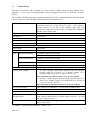
Figure 1a: Front view of ventiPAC showing accessories, features and the EP option ....................... 13
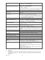
Figure 1b : Rear and side view of ventiPAC .................................................................................... 17
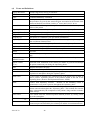
Figure 1c : Detachable part of ventilator breathing system for demand version ................................ 19
Figure 2a and Figure 2b
Figure 2c........................................................................................ 21
Figure 2d
Figure 2e
.......................................................................................................... 21
Figure 3: Connection of the patient valve / PEEP valve/ Exhaust collector accessories ................... 22
Figure 4: Contents of Instant Action Set option and correct stowage............................................... 26
Table 1: ventiPAC 200D User Information Label ............................................................................ 36
Figure 5: Principle of operation of the demand version of the ventiPAC ventilator .......................... 43
Pneupac reserves the right to make changes, without notice, which may affect the information
contained in this manual.
Trademarks: The names "Pneupac", “ventiPAC” "ventiPAC 200D","Instant Action" and "Smiths"
are registered trademarks of Smiths Group plc.
504-1117A
4
SECTION 1: SUMMARY STATEMENT
The ventiPAC 200D ventilators are portable devices intended for the ventilation of adults, children
and infants (above 10kg) during transportation and emergency situations. They consist of a control
module and a remote patient valve, connected by means of a breathing hose. Both pneumatic and
electronic alarms are incorporated.
WARNING: Failure to read this User’s Manual before first use of this device may result in death
or serious injury
Before use for the first time, all potential users must read the complete User’s Manual, they should
also familiarise themselves with the machine and its operation to enable them to use it effectively.
They should study the contents of this Manual to the extent required to supplement their training.
Special attention must be paid to warnings and precautions which are summarised in section 1(b).
Failure to observe these warnings and precautions could compromise patient and/ or user safety.
Special guidance on the operation and use of the ventilator is given in section 4 of this manual and
basic operating instructions are provided on the label affixed to the control module.
WARNING: To avoid harm to the patient, this equipment should only be used by personnel
trained in the use of automatic ventilation (SECTION 1(a)).
The equipment should only be used by medical personnel who have a full understanding of the
techniques required for its use, or paramedical personnel who have received full and proper initial
and 'refresher' instruction from a qualified person, both on resuscitation and on detailed use of the
equipment in the situations in which it is likely to be employed.
Information given in this manual
beyond the basic operation of the ventilator is only intended as a guide to supplement proper medical
training and to indicate the specific operational requirements of the ventiPAC ventilator.
WARNING: Federal Law (USA) restricts the use or sale of this device by, or on the order of, a
physician.
WARNING: To avoid harm to the patient, this equipment should only be used by personnel
trained in the use of automatic ventilation.
WARNING: Failure to constantly monitor the patient whilst using this equipment may lead to
death or serious injury.
WARNING: Blood gas levels must be monitored independently, correct operation of the
ventilator will not necessarily achieve the required blood gas levels.
The ventiPAC ventilator is intended only for use in transport and emergency situations where the
patient is being constantly monitored by the carer. The integrated alarm unit is intended to alert the
carer to changes in the patient’s ventilation but it cannot ensure that the patient’s blood gases are
maintained at the required level. Therefore, patient monitoring devices e.g. a pulse oximeter and
other recommended devices should additionally be used where appropriate.
504-1117A
5
(a)
WARNINGS: -Warnings and Precautions
WARNINGS
Warnings are given to make you aware of dangerous conditions, that could lead to death or serious
injury to the user or patient, that can occur if you do not obey all of the instructions given in this
manual.
1.
WARNING: Failure to read this User’s Manual before first use of this device may result
in death or serious injury
2.
WARNING: Federal law (USA) restricts the use or sale of this device by, or on the order
of, a physician.
3.
WARNING: To avoid harm to the patient, this equipment should only be used by
personnel trained in the use of automatic ventilation. (SECTION 1(a)).
4.
WARNING: Failure to constantly monitor the patient whilst using this equipment may
lead to death or serious injury. (SECTIONS 1(a)).
5.
WARNING: Blood gas levels must be monitored independently, correct operation of the
ventilator will not necessarily achieve the required blood gas levels. (SECTION 1(a)).
6.
WARNING: Use of Oxygen (Section 3(a) and 3(b) 13 )
Avoid smoking or naked flame. To avoid the risk of ignition, do not use oil, grease or
combustible lubricants (only those approved for oxygen use) in contact with any part of
the ventilator, regulator or cylinder.
To avoid ignition by adiabatic compression, connect the ventilator to the regulator
before opening the cylinder valve slowly. Similarly, prior to changing cylinders, turn off
the cylinder valve, switching on the ventilator. When the ventilator stops, it is safe to
release the pin index yoke.
7.
WARNING: Use in Aircraft (Section 2(a))
To avoid the risk of explosion or interference, where used on aircraft, the use of this
equipment must be authorised by the Aviation Authority and the Aircraft Operator.
8.
WARNING: Use of CMV/Demand Facility (Section 2(d)2)
Because this function has characteristics specific to this range of ventilators it is
important that the sections of the operating instructions describing this facility (Sections
2(b) and 4(d)) are read before this version of the ventiPAC ventilator is used so that the
operator understands how the ventilator interacts with the patient during spontaneous
breathing.
504-1117A
6
9.
WARNING: Direct Patient Inflation Pressure Sensing - EP Option (1) (Section 2(d) (i)
and 2(d) (6))
Although there is no net flow in the sensing line it is recommended that a microbial filter
is always inserted in the sensing line to ensure that no patient contamination can enter
the manometer circuit within the control module.
10.
WARNING: Direct Patient Inflation Pressure Sensing - EP Option (2) (Section 2(d) (i)
and 2(d) (6))
Ventilators with the EP option must never be used without the sensing line attached as
this will result in a loss of ‘delivered volume’ to the patient and loss of patient pressure
indication on the manometer.
11.
WARNING: Battery for MRI Use (Section 2(d)15)
To avoid projectile risk in a MRI environment, use only the approved MRI compatible
battery, Part No: W269-023. Do not attempt to remove the battery from the ventilator
(or take a loose battery) in a MRI environment. (Section 2(d) # 15).
To prevent possible risk of projectile injury within a MRI environment, routinely check
for magnetic attraction.
12.
WARNING: Potential Unsatisfactory Performance with Alternative Ventilator Patient
Circuits (Section 2(d)18)
Failure to use approved circuits and accessories may lead to unsatisfactory ventilator
performance.
13.
WARNING: Special Patient Valve (Section 2(d)20)
The patient valve is specially modified to match it to the performance of the ventiPAC
ventilator and only valves supplied with the units, or bearing the specified part number,
should be used. Any other valve may compromise the ventilation performance of the
ventiPAC ventilator
14.
WARNING: Provision of Accessories, Ancillaries and Spares for CE marked products.
Section 2(f), 6(d) & 7)
The ventiPAC ventilator is manufactured and ‘CE’ marked to the requirements of
93/42/EEC. To ensure that this equipment functions as intended, use only the
manufacturer’s authorised spares.
15.
WARNING: Use of Clausen Harness (Section 2(f) (vii))
Because the operator is no longer supporting the head and chin, particular care must be
taken that the victim’s airway is maintained open during these procedures and constant
checks should be made for gas availability and correct ventilator function.
504-1117A
7
16.
WARNING: Functional Check (Section 3(b)13)
Deviations noted at functional check should be reported immediately to Pneupac and the
unit must be taken out of service to avoid the risk of death or serious injury.
17.
WARNING: Pre-Use Checks
To avoid harm to the patient, pre-use checks must be performed (See Section 3(a) and
3(b) Points #1 to #8 inclusive) before each use.
18.
WARNING: Release of Cylinder Pressure (Section 3(b)2 and 3(b)13)
To avoid ignition by adiabatic compression, connect the ventilator to the regulator
before opening the cylinder valve slowly. Similarly, prior to changing cylinders, turn off
the cylinder valve, switching on the ventilator. When the ventilator stops, it is safe to
release the pin index yoke.
19.
WARNING: Provision of Alternative Means of Ventilation (Section 4)
Always ensure that an alternative means of ventilation is available in the event of
ventilator failure or malfunction
20.
WARNING: Adequacy of Gas Supply (Section 4(b)(ii))
To ensure that ventilation can be maintained without interruption keep a constant check
on the adequacy of gas supply by observing the gas cylinder contents indicator and the
gas failure visual alarm.
21.
WARNING: Interpretation of ‘Breathing Detect’ Indicator (Section 4(d))
Actuation of the ‘breathing detect’ indicator only indicates that spontaneous breathing
has been detected and that the low-pressure alarm has been reset as a consequence. The
operator must still ensure that patient ventilation is adequate.
22.
WARNING: Use in Contaminated Atmosphere (1) (Section 4(g))
The ventiPAC ventilator models are suitable for use in contaminated and toxic
atmospheres subject to certain limitations as described below and these should be clearly
understood by those likely to use the equipment in such environments so that it is only
used where appropriate.
23.
WARNING: Use in Contaminated Atmosphere (2) (Section 4(g))
In any situations where the respirable qualities of the immediate environment are
suspect, ventilation should only be carried out in the ‘No Air Mix’ mode. This ensures
that only a minimum of ambient gas can enter the breathing system.
504-1117A
8
24.
WARNING: MRI Use (Section 4(h))
To prevent possible risk of projectile injury within a MRI environment, routinely check
for magnetic attraction.
When in use in a MRI environment, to prevent injury to the patient, check the pressure
manometer to confirm unchanged ventilation. Also, test the high-pressure relief/alarm
system by temporary circuit disconnection and occlusion of the ventilator outlet
connector, both whenever the system is taken into a MRI environment, and every time
the patient is positioned within the magnetic field.
25.
WARNING: Training Requirements (section 4(i)(ii))
All operators who are not medically qualified should receive full and proper instruction
from a qualified person, both on resuscitation and on detailed use of the equipment in
the particular situations in which it might be employed (see Section 1(a))
26.
WARNING: Use in Extreme Environments (Section 4 and Appendix B)
Extreme environments may impair ventilator performance (see Appendix B), operator
vigilance is required to monitor the patient.
27.
WARNING: Lithium batteries are of the primary type and are NOT designed to be
recharged. Attempts to recharge these batteries can lead to leakage and possibly an
explosion. (Appendix A).
28.
WARNING: Do not use this ventilator in very confined spaces, as oxygen concentration
will be affected, due to expired gas from the expiration valve entering the fresh gas
intake port. Where fitting in a confined space is necessary, consult Pneupac for
installation advice. (Section 2(e) ii)).
CAUTIONS:Cautions warn of dangerous conditions that can occur and cause damage to the ventilator or its
accessories, if you do not obey all of the instructions given in this manual.
1.
CAUTION: When storing for long periods, to avoid the risk of possible corrosion or drain
of the battery, ensure that the ventilator is left in the ‘off’ position and the battery
removed. (Section 2(d) # 15).
2.
CAUTION: To ensure that the cylinder contents are not lost during storage due to small
leakages, it is recommended that the valve on the gas cylinder is turned off after use.
(Section 2(b)13).
3.
General Precautions Relating to Battery Safety, Transportation and Disposal.
See Appendix A.
4.
CAUTION : To avoid damge to the EP circuit, detach all EP Circuit parts from the
Patient Hose prior to autoclaving. DO NOT autoclave EP Accessories.
504-1117A
9
PRECAUTIONS: Precautions warn of actions required to avoid dangerous or undesirable conditions that can occur and
cause damage to the ventilator or its accessories, if you do not obey all the instructions given in this
manual.
1.
PRECAUTION: Protection of Battery and Ventilator During Periods Without Use
(Section 2(d)15)
To avoid any drain on the battery if the ventilator is unlikely to be used for a long time
or is placed in storage, ensure that the main pneumatic switch is left in the 'Demand'
(ventilator off) position. It is also recommended that the battery is removed from its
holder to avoid possible corrosion due to leakage of its contents.
2.
PRECAUTION: Prevention of Gas Loss (Section 3(b)13)
It is recommended that the valve on the gas cylinder is turned off after use to ensure that
the cylinder contents are not lost during storage due to small leakages.
3.
PRECAUTION: General Precautions Relating to Battery Safety, Transportation and
Disposal. See Appendix A
504-1117A
10
SECTION 2: GENERAL INFORMATION
(a)
Intended Use
The ventiPAC 200D is a portable ventilator designed for the ventilation of adults, children and infants
in and outside hospitals by personnel with medical training. It is particularly suitable for ventilation
during transportation and for providing rescue breathing and emergency resuscitation by well trained
operators.
The 200D model is especially suitable for the treatment of victims in rescues from toxic or non
respirable atmospheres as it offers the choice of 100% oxygen upon demand or ventilatory back-up to
the patient whilst normal breathing is being restored.
This CMV*/Demand feature may also be used for weaning patients back to normal breathing from
controlled ventilation.
These ventilators are designed to be extremely economical in their use of driving gas and the 'Air
Mix' mode makes them particularly suitable for the long distance transport of patients using bottled
oxygen or air (see Section 8(b)).
The ventiPAC ventilators and associated equipment described in this manual conform to European
Standard EN794-3 "Particular Requirements for Emergency and Transport Ventilators" and comply
with the requirements of the European Directive for Medical Devices 93/42/EEC.
WARNING: To avoid the risk of explosion or interference, where used on aircraft, the
use of this equipment must be authorised by the Aviation Authority and the Aircraft
Operator.
(b)
General Description
WARNING: Use of CMV/Demand Facility
Because this function has characteristics specific to this range of ventilators it is
important that the sections of the operating instructions describing this facility (Sections
2(b) and 4(d)) are read before this version of the ventiPAC ventilator is used so that the
operator understands how the ventilator interacts with the patient during spontaneous
breathing.
The ventiPAC ventilator consists of a control module and a remote patient valve, connected by means
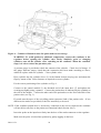
of a spirally reinforced hose. (See Fig 1a)
A description of controls and features on the ventiPAC ventilator is given in Section 2(a), the number
reference against each description corresponds to the number reference shown in Figure 1a.
The ventiPAC ventilator is a gas powered, time cycled ventilator which depends solely on the
pressure of the supply gas for its operation. The models described in this Manual additionally
incorporate an integrated electronic pressure alarm unit to alert the user to certain significant changes
which may occur in the patient’s ventilation. Loss of battery power for the alarm is signalled to the
user but will have no effect on the ventilation performance of the ventiPAC ventilator, nor affect the
mechanically operated alarms and protection systems.
* See Terms and Definitions, Section 8 (d).
504-1117A
11
The control module of the ventiPAC ventilator is rugged by virtue of its thick section structural foam
plastic case and the use of anti-shock mountings for the gauge, internal pneumatics and electronics.
The controls are recessed to minimise the possibilities of damage.
Calibrated controls for inspiratory time, expiratory time and inspiratory flow are provided to set the
required ventilation pattern. An adjustable pressure relief device with an audible alarm limits the
peak inspiratory pressure to the set value.
An air mix control gives an FiO2 option of 0.45 or 1.0. For longer term ventilation the 0.45 FiO2
setting will normally be used and in this setting gas consumption is significantly reduced - by almost
70% - giving greatly extended cylinder duration or allowing the use of a much smaller compressor if
compressed air is used as the driving gas.
On the ventiPAC 200D ventilator, selection can be made between 'Demand' or 'CMV/Demand'.
When 'CMV/Demand' is selected, the ventilator cycles at the set frequency but if a spontaneous
breath is taken during an exhalation phase then this is taken from an internal demand valve. If
breathing is at an adequate level for an adult, cycling will be inhibited as long as this breathing level
is maintained. If breathing becomes inadequate, CMV will be restored, synchronised with the last
breath.
When ‘Demand’ is selected, only the internal demand valve is energised by the gas supply. When the
patient is connected to the patient valve any spontaneous breathing effort is satisfied by flow from the
demand valve. This provides a very gas efficient method of treating a victim where 100% oxygen is
recommended as the approved therapy and can also be used to protect a spontaneously breathing
patient during rescue from a contaminated atmosphere.
The control module is designed to be mounted in a variety of ways as described under Section 2 (d)
(ii) 'Mounting Options'. A sling is available to enable the unit to be carried from the user's shoulder.
It may also be carried, together with a compressed gas cylinder, within a Pneupac 'Instant Action'
carrying case. A wide range of attachments and brackets is also available. The ventiPAC ventilator
may be driven by oxygen or air from a compressed gas cylinder, pipeline system, or one of the
airPAC portable compressors.
504-1117A
12
Figure 1a: Front view of ventiPAC showing accessories, features and the EP option
(c)
Contraindications
None known.
(d)
1.
Controls and Features (Figures 1a and 1b)
Controls for Inspiratory and Expiratory Times.
These calibrated rotary control knobs give continuous adjustment of time over the range of 0.5
to 3.0 seconds for inspiration and 0.5 to 6.0 seconds for expiration.
Together, these controls set the breathing frequency which can be calculated as 60/TI+TE.
e.g. if the inspiratory time is set to 0.75 second and the expiratory time 1.25 seconds then the
frequency is 60/1.25 + 0.75 = 60/2 = 30 breaths per minute. The ratio of Inspiratory Time to
Expiratory Time (I:E ratio) can be set as required. Typically this will be set at 1:2 or within
the range 1:1 to 1:3.
2.
Frequency Flow Control
This rotary control knob gives continuous adjustment of delivered ventilatory flow over the
range 0.1 to 1.0 litres per second. Between 0.25 and 1.0L/sec this flow is relatively unaffected
by lung compliance and airway resistance or by switching between 'Air Mix' and 'No Air
Mix'. At lower flow settings with 'Air mix' selected the delivered flow becomes increasingly
dependent upon the inflation pressure being generated as explained in Section 4(c).
504-1117A
13
The product of flow (in L/sec) and inspiratory time (in seconds) gives the delivered tidal
volume (in litres) e.g. if the flow is set to 0.5 L/sec and the inspiratory time to 1.0 second the
delivered tidal volume is 0.5 x 1.0 = 0.5 litre = 500ml.
3.
Main Pneumatic Switch
This knob operates a rotary switch to select 'Demand' only or the 'CMV*/Demand' facility
which provides controlled mandatory ventilation to non breathing patients but which allows
inhibition if an adult patient commences spontaneous breathing to an adequate level.
WARNING: Because this function has characteristics specific to this range of
ventilators it is important that the sections of the operating instructions describing this
facility (Sections 2(b) and 4 (d)) are read before this version of the ventiPAC ventilator is
used so that the operator understands how the ventilator interacts with the patient
during spontaneous breathing.
Selection of 'CMV*/Demand' also switches on the electronic alarm but for the first 60 seconds
of the ventilator operation most of the alarm functions are automatically suspended in order to
allow time to apply the ventilator to the patient. Selection of 'Demand' switches off the alarm
unit.
4.
Relief Pressure Control
This rotary control knob gives continuous adjustment of the maximum patient inflation
pressure by setting the relief valve spring loading. It is calibrated to facilitate initial setting
but as the peak pressure will also have some dependence upon other parameters the inflation
pressure monitor should always be used as the final reference.
5.
Air Mix Control
This knob operates a rotary two position switch to select the 'Air Mix' or the 'No Air Mix'
mode.
In the 'No Air Mix' position the gas supplied to the ventilator is passed undiluted to the patient
- whether this be 100% oxygen or compressed air.
In the 'Air Mix' mode the ventilator uses a high efficiency entrainment device to mix ambient
air with the supply gas in the ratio of approximately 2:1. When supplying oxygen, this means
that a mixture containing 45% oxygen is generated and supplied to the patient.
When air is used as the driving gas no change of gas composition occurs but advantage can be
taken of the 70% reduction in driving gas consumption which is achieved in the 'Air Mix'
mode.
6.
Inflation Pressure Monitor
This pressure manometer displays the patient inflation pressure, as measured at the ventilator
outlet. It will give an accurate indication of the actual patient proximal inflation pressure
under all normal settings of the ventilator. It will not display exhalation pressure although
this will only be relevant if attachments such as a PEEP valve are added to the patient valve.
* See Terms and Definitions, Section 8(d)
504-1117A
14
This arrangement is to be preferred for emergency use because it requires the simplest patient
circuit and there is less probability of disconnection occurring as a result of snagging of the
circuit.
The /EP model option provides external pressure sensing connectors and an external sensing
line so that the inflation pressure can be measured at the patient connection point. This may
be considered an advantage if the ventilator is to be used mainly for patient transport and
PEEP is frequently used (See Section 2(d)(i)). PEEP value will also be shown if the circuit is
connected properly.
WARNING: Direct Patient Inflation Pressure Sensing - EP Option (1) Although there is
no net flow in the sensing line it is recommended that a microbial filter is always inserted
in the sensing line to ensure that no patient contamination can enter the manometer
circuit within the control module.
WARNING: Direct Patient Inflation Pressure Sensing - EP Option (2)
Ventilators with the /EP option must never be used without the sensing line attached as
this will result in a loss of ‘delivered volume’ to the patient.
7.
Supply Gas Failure Alarm
This mechanically operated visual alarm gives a warning that the supply gas has dropped to a
pressure at which the ventilator will no longer be operating to specification. With low
pressure it shows red, with adequate pressure it shows white. Any visible red indicates that
the supply should be changed. In most cases the display will begin to oscillate from white to
partial red as the supply pressure falls to the lower threshold level.
The visual indication will be accompanied by an electronically generated medium priority*
audible warning. In order to conserve the battery, if this audible alarm is ignored for more
than 60 seconds the alarm system will ultimately switch itself off.
8.
High Inflation Pressure Alarm
An audible alarm is provided to signal that the relief pressure has been achieved and that gas
loss is occurring through the relief valve. The alarm is pneumatically operated by means of
the gas vented through the relief valve.
The pneumatically operated alarm is backed up by a high priority* electronically generated
audible and visual alarm. The electronic audible alarm only sounds after alarm pressure has
been maintained for a period of 1.0 second in order to avoid the simultaneous sounding of
both alarms during transient pressure events. Initially the visual alarm only indicates each time
the pressure reaches the preset limit but if high pressure conditions persist the alarm latches to
give continuous flashing.
Both the audible and visual alarms reset automatically after 10 seconds when the condition is
no longer present.
* See Terms and Definitions, Section 8(d)
504-1117A
15
9.
Cycle Indicator
During ventilation of the patient the inflation pressure is continuously monitored by a positive
pressure detector pre-set to 10 x100Pa (10cmH2O). Each time the inflation pressure rises
through this set pressure level the green Cycle Indicator* flashes for 1/10 second to indicate to
the user that, at least, this inflation pressure is being achieved each cycle.
10.
Low Inflation Pressure (Disconnect) Alarm
A medium priority* audible and visual alarm will operate to warn the user of a possible
disconnection in the ventilator breathing system or that the ventilator is not cycling correctly if
the inflation pressure generated by the ventilator does not rise through the pre-set level of 10
x100Pa (10cmH2O) at least once in any 10 second period. It should be noted that during
normal functioning of the ventilator the generated pressure is always zero during the
expiratory phase even if PEEP is applied at the exhalation port of the patient valve. Both the
audible and visual alarms reset when the alarm condition no longer exists.
11.
Constant Positive Inflation Pressure Alarm
A high priority audible and visual alarm will operate to warn the user of a possible danger to
the patient if the inflation pressure remains at a positive pressure above the preset pressure
threshold of 10 x100Pa (10cmH2O) but below the set Relief Pressure for a period exceeding
10 seconds unless this is due to the application of high levels of PEEP.
12.
Silencing of Electronic Audible Alarms
A visual signal, consisting of an orange light flashing every 3 seconds, is used to indicate
when an electronically generated audible alarm has been silenced. For the first 60 seconds
after switching on the ventilator ('CMV/Demand' selected) all alarms, except the supply gas
failure alarm, are automatically suspended although high priority visual alarms will still
operate. Any audible alarm can be silenced for a 60 second period, subsequently, by
depressing the silencing button but if a new alarm condition occurs during this period it will
be immediately annunciated.
If the silencing button is depressed pre-emptively, i.e. before any alarm sounds, then only a
new high priority alarm condition will cause an alarm to sound during the following 60
seconds.
13.
Breathing Detect Indicator
A green visual indicator is used to indicate that a spontaneous breathing effort has been
detected by the demand detector in the ventiPAC ventilator. Each time detection occurs the
low inflation pressure (disconnect) alarm is reset in the same way as a positive pressure resets
the alarm in normal ventilation. This ensures that nuisance alarms do not occur due to the
absence of positive ventilation when the patient is breathing spontaneously.
* See section 8(e) & (f) for explanation of symbols and description of alarm priorities.
504-1117A
16
14.
Low Battery Alarm
A yellow visual indicator is used to indicate that the internal battery used to power the alarm
unit, is giving reduced voltage. With the 123A battery it will flash once every 30 seconds for
several hours of use as an early warning that the battery will need to be replaced. With both of
the recommended batteries the flashing rate will increase to twice every second, accompanied
by a medium priority audible alarm, for the final few minutes of the battery life. When
operating at very low temperature the life of the battery will be reduced.
When the alarm is operating normally, as indicated by flashing of either the silencing indicator or one
of the two green indicators, the absence of any signal from the low battery indicator confirms that the
battery voltage is adequate to operate the alarm system correctly. Refer to Section 6(c) for
recommendations concerning battery replacement.
Figure 1b : Rear and side view of ventiPAC
15.
Battery
The electronic alarm unit is powered by means of a single cell lithium battery retained in a
battery holder on the right hand side of the ventilator. There are two, alternative-sized
batteries which can be fitted. For normal use the readily available size 123A 3V lithium
battery, as widely used in cameras, can be fitted. However, in MR environments it is essential
that the special low ferrous content battery, supplied by Pneupac and marked “For use in MR
Compatible ventilators”, is used. This battery is in a size AA packaging but provides 3.6V
and has a non-metallic casing. It has been specially selected as having minimal ferrous
content such that when installed in the ventilator it produces no noticeable effect. Only this
battery should be used when the ventiPAC 200D is used as an MR Compatible ventilator.
It must be noted that no battery of this type, commercially available, is completely free of
ferrous content and so it must never be removed from the battery compartment of the
ventilator in the presence of a magnetic field.
* See section 8(f) for explanation of description of alarm priorities.
504-1117A
17
The battery is retained by means of a reversible retaining cap which is removed by a quarter
turn anti-clockwise twist using a coin in the slots provided. During insertion of a new battery
the cap should be orientated according to the battery type being used. With the MRI battery
inserted, the cap should be fitted with the yellow "MRI" visible after assembly whereas with
the standard size 123A battery the "MRI" with a red cross through it should be visible.
Lithium batteries have an expected shelf life of 10 years and there is no current drain on an
installed battery when the babyPAC ventilator is switched off. Under general use conditions
the specified batteries will give at least one year's service before requiring replacement.
CAUTION: When storing for long periods, to avoid the risk of possible corrosion or
drain of the battery, ensure that the ventilator is left in the ‘off’ position and the battery
removed.
WARNING: BATTERY FOR MRI USE
WARNING: To avoid projectile risk in a MRI environment, use only the approved MRI
compatible battery, Part No: W269-023. Do not attempt to remove the battery from the
ventilator (or take a loose battery) in a MRI environment.
WARNING: To prevent possible risk of projectile injury within a MRI environment,
routinely check for magnetic attraction.
PRECAUTION: To avoid any drain on the battery if the ventilator is unlikely to be used
for a long time or is placed in storage, ensure that the main pneumatic switch is left in
the 'Demand' (ventilator off) position. It is also recommended that the battery is
removed from its holder to avoid possible corrosion due to leakage of its contents.
16.
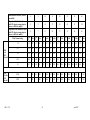
Basic Operating Instructions
This panel on the ventilator gives basic operating instructions to assist the infrequent user of
the ventiPAC ventilator. It is not intended to replace, in any way, the more comprehensive
instructions and information given in this handbook. A chart on the label provides a useful
look-up table for easy determination of Tidal Volume and Frequency with reference to
Inspiration Time, Expiration Time and Flow.
17.
Alarm Information Label
This label provides alarm battery information and a key to alarm signals.
504-1117A
18
Figure 1c : Detachable part of ventilator breathing system for demand version
18.
Patient Outlet Connection
This outlet to the patient from the ventilator is intended for the attachment of the patient
circuit supplied by Pneupac for this purpose.
WARNING: Failure to use approved circuits and accessories may lead to unsatisfactory
ventilator performance.
19.
Patient Hose
The patient valve is connected to the control module by means of a spirally reinforced smooth
bore ventilation hose. It may be autoclaved at temperatures up to 134°C (See Section 5 (d)).
20.
Patient Valve
This valve directs the inspiratory flow from the ventilator into the lungs during the inspiratory
phase and allows expiration to the atmosphere. The connection to the patient is by means of
an 22/15mm co-axial taper fitting so that face masks or endotracheal tubes conforming to the
requirements specified in EN 1281-1 may be used. It may be autoclaved at temperatures up
to 134°C.
On Model 200D ventilator, the yellow rubber disc covering the expiratory port serves as a
non-return valve to ensure that the patient always inspires from the ventilator and not directly
from the atmosphere through this port. (See Fig. 1c)
WARNING: The patient valve is specially modified to match it to the performance of
the ventiPAC ventilator and only valves supplied with the units, or bearing the specified
part number, should be used. Any other valve may compromise the ventilation
performance of the ventiPAC ventilator.
504-1117A
19
21.
Inlet Connection
A compact, screw type input connection is provided which is specifically designed to take the
input hose provided by Pneupac to make a permanent connection. Alternative, gas specific,
user detachable connections can be provided by Pneupac if specified at the time of ordering.
22.
Input Hose
A range of input hoses is available with alternative connections and probes to suit different
gases and Standards requirements.
23.
Carrying Sling Attachments Slots.
The carrying sling, W7140, is attached to the control module by means of slots as shown in
Fig. 1b.
24.
Mounting Attachment Points
Six M5 x 1.0 x 7 deep female threaded bushes on the back of the control module may be used
for the attachment of brackets for direct mounting.
(e)
(i)
Options Covered by this Manual
Model Option
Direct patient inflation pressure sensing (/EP option)
As explained in Section 2(c)6 ventilators supplied against the suffix /EP are arranged to sense the
patient inflation pressure directly at the patient outlet connection (refer to Figure 1a). The sensing
port is mounted in an adaptor which couples to the 22mm taper of the patient connection.
The
sensing line is connected between the port and a male connector on the side of the ventiPAC
ventilator. The line is secured to the patient hose at intervals by means of the clips supplied. If used
correctly with the PEEP valve, the actual PEEP value will be shown.
WARNING: Although there is no net flow in the sensing line it is recommended that a
microbial filter is always inserted in the sensing line to ensure that no patient contamination
can enter the manometer circuit within the control module.
WARNING: Ventilators with the /EP option must never be used without the sensing line
attached as this will result in a loss of 'delivered volume' to the patient.
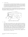
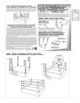
(ii)
Mounting Options
The ventiPAC ventilator has been designed to be mounted and carried with a wide range of options as
shown in Fig 2.
It may be mounted with its base or back on a flat surface as shown in Figs 2 (a) and 2 (b).
Alternatively it can be carried on the shoulder by means of the carrying sling as shown in Fig 2 (c).
504-1117A
20
Figure 2a and Figure 2b
Figure 2c
For more permanent installations ventiPAC ventilators can be fitted with a rail or pole
mounting bracket as shown in Fig 2 (d) and 2 (e). The brackets are attached to the back of
the control module by means of two M5 x 1.0 socket head fixing screws supplied with the
bracket. The rail bracket is of the universal type and attaches to 35/30 mm rails of either 6.5
or 10 mm thickness and of the form shown in Fig 2 (d). A quick release clamp with a screw
back-up is used.
The pole mounting bracket attaches to the module in the same way and accommodates vertical
pole diameters of 1/2 - 1" (12 - 26 mm). A screw with a T-handle is used for clamping.
Figure 2d
Figure 2e
WARNING: Do not use this ventilator in very confined spaces, as oxygen concentration will be
affected, due to expired gas from the expiration valve entering the fresh gas intake port. Where
fitting in a confined space is necessary, consult Pneupac for installation advice.
504-1117A
21
(f)
Accessories
WARNING: Failure to use approved circuits and accessories may lead to unsatisfactory
ventilator performance.
(i)
Instant Action Case
An Instant Action carrying case can be supplied which is specially designed to carry a
ventiPAC ventilator, a 'D' sized gas cylinder and a wide range of accessories. It enables a
comprehensive set of pulmonary ventilation equipment to be carried for immediate action at
the scene of an emergency.
Fig 3 shows the general arrangement of the set opened out ready for action and complete with
the optional gas powered aspirator and an oxygen therapy set. Velcro fasteners are used to
ensure easy and reliable access even under the most extreme conditions. Pockets and straps
are available for accessories such as PEEP valves, Guedel airways and alternative masks.
(ii)
Gas Cylinders
Lightweight aluminium compressed gas cylinders are available from Pneupac for use with
portable ventilators. The 'D' sized version is suitable for use with the Instant Action Case, but
it is flat based which permits free standing use also.
(iii)
Cylinder Regulators
The Pneupac lightweight aluminium regulator is designed to reduce the pressure of high
pressure gas cylinders from 137-200 x100kPa (137-200 bar) to 400kPa (4 bar) as required by
the ventiPAC ventilator. It will deliver flow in excess of 60 L/min at this nominal pressure.
Pin index or other standard inlet connectors are available for air or oxygen. The regulator is
equipped with a protected contents gauge and a gas specific quick-release outlet connector
which accepts the BS probe on the ventiPAC input hose.
Figure 3: Connection of the patient valve / PEEP valve/ Exhaust collector accessories
504-1117A
22
(iv)
Oxygen Therapy Unit
The Pneupac Oxygen Therapy Unit consists of a flow-regulating 2 metre lead with a built-in
filter and disposable face masks.
The lead connects to the cylinder regulator outlet connector and delivers 6 litres per minute of
oxygen to the mask whose design ensures that the patient receives approximately 40-45%
oxygen in the mask. This lead may also be used with a nebuliser.
(vi)
PEEP Valves
The Pneupac patient valve supplied with the ventiPAC ventilator can be fitted with a PEEP
valve by means of an exhaust collector (see Fig. 3). This collector is a push fit onto the body
of the patient valve and connects the exhalation ring to a 30 mm male taper connection port
without interfering with the function of the valve. Pneupac can supply a compact PEEP valve
to fit onto this port with an adjustment range of 0-20 x100Pa (0-20cmH2O). PEEP setting is
by means of a calibrated adjustment knob.
Before using PEEP with the ventiPAC ventilator refer to Section 4 (f) of this Manual.
(vii)
Clausen Harness and Hook Ring
A Clausen harness and Hook ring can be supplied to strap the face mask to the victim's face
for rescue from difficult situations e.g. in tunnel rescue or when hoisting.
WARNING: Because the operator is no longer supporting the head and chin particular
care must be taken that the victim's airway is maintained open during these procedures
and constant checks should be made for gas availability and correct ventilator function.
504-1117A
23
Page Intentionally Blank
504-1117A
24
SECTION 3: SET-UP AND FUNCTIONAL CHECK
(a)
Set Up
(i)
ventiPAC ventilator
Unpack the ventiPAC control module and accessories and check all items against the contents
checklist. If any items are missing or incorrect or have become damaged notify your supplier
immediately.
If a carrying sling or mounting bracket has been supplied attach it to the module as shown in
Figure 2. Insert the battery into the module battery holder as described in Section 6(c).
Because there is no battery fitted in the holder it will be necessary to tip up the module in
order to remove the battery retaining cap. Assemble the patient circuit and connect it to the
control module as shown in Fig 1 (a). Note that the hose is attached to the fixed taper limb of
the patient valve which is at an angle to the body. The mask is attached to the swivel taper.
Connect the input hose to the inlet connector as shown in Figure 1(a) and tighten the securing
nut lightly using a spanner (wrench).
The probe on the input hose is gas specific to the standard specified when ordering. Any of
the Pneupac hoses listed in the ventiPAC Accessories and Spare Parts List can be used with
the ventilator provided the same inlet connection is specified.
(ii)
Instant Action Set
Unpack the equipment and lay out the contents so that each component is identified.
reference to the illustration (Fig 4) for the stowage of all items.
Make
Lightweight aluminium Pin Index 'D' size cylinders may be purchased from Pneupac.
WARNING: Avoid smoking or naked flame. To avoid the risk of ignition, do not use oil,
grease or combustible lubricants (only those approved for oxygen use) in contact with
any part of the ventilator, regulator or cylinder.
Remove plastics wrapper from cylinder valve. Momentarily turn on cylinder using cylinder
valve key/wheel to blow out any dust in cylinder valve. Fit regulator and yoke (1) to the
cylinder valve, making sure the sealing washer is in position and the two foolproofing locating
pins are entered in the side of the square cylinder valve. Tighten the T screw in the yoke
making sure that the screw's pointed end is in the recess of the cylinder valve. Where a
regulator with a threaded cylinder connection fitting is provided, screw the fittings onto the
threaded connection of the cylinder, tightening with the regulator in the correct orientation to
fit the case.
Slowly turn on cylinder using the cylinder valve key/wheel. Open cylinder by two anticlockwise turns of the cylinder valve wheel. Check that gas does not leak audibly from the
connection or from the gland nut on the cylinder valve. If leaking, check that the previous
fitting instructions have been carried out properly and that the sealing washer is in position
and is not damaged. If the leak is not rectified, replace the cylinder and defer the faulty
cylinder via the normal reporting channel.
504-1117A
25
Figure 4: Contents of Instant Action Set option and correct stowage
WARNING: To avoid ignition by adiabatic compression, connect the ventilator to the
regulator before opening the cylinder valve slowly. Similarly, prior to changing
cylinders, turn off the cylinder valve, switching on the ventilator. When the ventilator
stops, it is safe to release the pin index yoke.
A pressure gauge is provided to check the contents of the cylinder. Check level of charge. If
the gauge indicates empty, check that the connection has been made according to above,
otherwise replace with new cylinder. Close cylinder valve.
Place cylinder into the cylinder sleeve (2) in the Instant Action carrying case and adjust the
flaps by means of the Velcro fasteners as required to secure cylinder.
For the correct positioning of the cylinder see Fig. 4.
Connect to the control module (3) the threaded end of the input hose (7) and tighten the
securing nut lightly using a spanner. Connect the patient hose as indicated by the symbols on
the side of the module. Connect the other end of the patient hose to the fixed side limb of the
patient valve (see Fig. 3.).
Fit mask onto the taper of the swivelling patient connector limb of the patient valve. If two
different size masks are provided, fit the size most likely to be used.
NOTE: If the ventilator patient hose is, incorrectly, connected to the swivel connector the ventilator
will not deliver any flow to the patient (see functional check Section 3(b)5).
Insert the probe on the input hose firmly into the bore of the outlet connector on the regulator.
Make sure the probe is locked into position by gently tugging on the hose.
504-1117A
26
Attach control module to side of case by means of the two thumb screws provided.
Coil hoses neatly so that case can be closed up without distorting them unduly.
Stow Guedel airways (4) in the individual elastic loops provided.
Coil and stow shoulder strap in the end loop.
Stow accessories as provided - the spare mask and Clausen harness in the loops, the antiinhalation valve, PEEP valve and any other items in the shallow side pocket. Place Oxygen
Therapy Set in the large side pocket.
The aspirator (5) is retained by loops in the end wall
and the suction tube and probe are stowed in the adjacent pocket. For details of accessories
see Section 2(e).
Place this Manual (6) in the central pocket for use and reference.
WARNING: To avoid harm to the patient, pre-use checks must be performed before
each use.
(b)
Functional Check
The following procedure should be followed when first setting up the ventilator to check that
it has been assembled correctly and is operating safely. It should be repeated periodically as
specified under 'Maintenance'.
1.
Check the ventilator controls as follows:Main Pneumatic Switch:
Inspiratory Time:
Expiratory Time:
Inspiratory Flow:
Air Mix Switch
Relief Pressure:
2.
'CMV/Demand'
1.5 Seconds
3.0 Seconds
0.5 L/sec
'No Air Mix'
40 x100Pa (40cmH2O)
Connect the probe on the input hose to an appropriate gas outlet.
WARNING: Avoid smoking or naked flame. To avoid the risk of ignition, do not use oil,
grease or combustible lubricants (only those approved for oxygen use) in contact with
any part of the ventilator, regulator or cylinder.
WARNING: To avoid ignition by adiabatic compression, connect the ventilator to the
regulator before opening the cylinder valve slowly. Similarly, prior to changing
cylinders, turn off the cylinder valve, switching on the ventilator. When the ventilator
stops, it is safe to release the pin index yoke.
3.
If connected to a cylinder regulator turn on cylinder valve slowly.
NOTE:The gas source must be capable of maintaining a pressure of at least 305 kPa (≈ 3 bar)
whilst delivering a flow of 65 L/min.
4.
Check that the visual alarm for supply gas failure has changed from red to white.
504-1117A
27
5.
Switch the main pneumatic switch to 'CMV/Demand'. The ventilator should commence
cycling and all the alarm lights flash in turn. A single burst of the high priority audible alarm
is given at the same time. The orange silencing indicator should flash for 60 seconds. Check
that the flow is coming from the patient connection port by feeling the flow when placed close
to the back of the hand or to the face.
6.
Occlude the output port on the patient valve and check that the manometer gives a reading of
between 30 and 50 x100Pa (30 and 50cmH2O) during each inspiratory phase. The pneumatic
audible alarm should also sound, accompanied by the high inflation pressure visual alarm.
After occlusion for one second, once the silencing period has elapsed, the high priority
electronic audible alarm will also sound. Check that the unit cycles regularly about every 5
seconds.
7.
Switch over to 'Air Mix' and repeat step 6. The change in the manometer reading should not
exceed 5 x100Pa (5cmH2O).
NOTE:After the 60 second initial silenced period the electronic audible alarms will operate if
an alarm condition persists. These can be silenced for as long as required by depressing the
silencing button each time the silencing indicator switches off.
8.
Set the ‘Flow’ control to its minimum setting. Occlude the output port and check that at least
20 x100Pa (20cmH2O) pressure is attained on the manometer. Gradually increase the flow
setting and observe how the pressure rises - demonstrating the pressure generator principle.
At the 0.25 L/sec setting the pressure should be attaining the nominal set value.
9.
Reset the ‘Flow'’ control to its minimum setting and select 'No Air Mix'. Occlusion of the
output port should now cause the manometer to rise sharply to between 30 and 50 x100Pa (30
and 50cmH2O) and the alarms should operate.
10.
Allow the ventilator to cycle with no obstruction at the output port and check that the low
inflation pressure (disconnect) alarm operates after 10 seconds.
11.
Set the ‘TI’, ‘TE’ and ‘Flow’ control knobs to the extremes of their range. By listening to the
gas flow, check that the ventilator is responding to the controls and that no irregularities of
performance can be discerned.
12.
If the ventilator is likely to be used with small infants the following additional test should be
carried out during the periodic test and after reassembly of the patient valve every time it is
dismantled:Connect the ventilator to a gas source and set the inspiratory and expiratory times to give a
frequency of about 30 b/min, set the ‘Flow’ control to minimum and the air mix switch to 'Air
Mix'. Attach a flexible reservoir bag (preferably 1/2 litre) to the patient connector of the
patient valve and switch on the main pneumatic switch. Roll up the end of the reservoir bag
to decrease its effective volume until the end inspiration inflation pressure rises to about 10
x100Pa (10cmH2O). Check that this pressure can be attained consistently every breath. If it
cannot, dismantle the patient valve, turn the yellow valve element about a quarter of a turn and
reassemble and retest. If after two or three adjustments consistent performance cannot be
achieved the valve element must be replaced.
504-1117A
28
13.
Finally, set the controls as specified in step 1 so that the ventilator is left set for emergency
use.
WARNING: Deviations noted at functional check should be reported immediately to
Pneupac and the unit must be taken out of service to avoid the risk of death or serious
injury.
WARNING: Avoid smoking or naked flame. To avoid the risk of ignition, do not use oil,
grease or combustible lubricants (only those approved for oxygen use) in contact with
any part of the ventilator, regulator or cylinder.
WARNING: To avoid ignition by adiabatic compression, connect the ventilator to the
regulator before opening the cylinder valve slowly. Similarly, prior to changing
cylinders, turn off the cylinder valve, switching on the ventilator. When the ventilator
stops, it is safe to release the pin index yoke.
PRECAUTION: It is recommended that the valve on the gas cylinder is turned off after
use to ensure that the cylinder contents are not lost during storage due to small leakages.
504-1117A
29
Page Intentionally Blank
504-1117A
30
SECTION 4 OPERATION
WARNING: Always ensure that an alternative means of ventilation is available in the
event of ventilator failure or malfunction
WARNING: Extreme environments may impair ventilator performance (see Appendix
B), operator vigilance is required to monitor the patient.
(a)
User's Skill
See Summary Statement (Section 1(a))
WARNING: All operators who are not medically qualified should receive full and
proper instruction from a qualified person, both on resuscitation and on detailed use of
the equipment in the particular situations in which it might be employed (see Section
1(a))
(b)
(i)
Setting of Ventilator
General
The ventilator should always be left with the controls set in the position specified in the
functional check (Section 3(b)) to enable it to be brought into use with a minimum of readjustment. It should be stored with a suitable gas source or suitable wall outlets must be
known to be available. At least one mask should also be kept available for emergency use.
(ii)
Ventilating Patient
1.
Connect supply hose probe to gas supply.
2.
Slowly turn on gas supply(ies) (if relevant).
3
Check that the visual alarm for supply gas failure has changed from red to white.
4.
Turn main pneumatic switch to ‘CMV/Demand’.
5.
Check that the alarm indicators flash in sequence, to indicate correct function.
6.
Set ventilation parameters to suit the patient (refer to table 1 on page 35).
7.
Briefly occlude the patient connection port of the patient valve with the thumb.
Check that the peak inflation pressure reading on the manometer is appropriate for
the patient and that the pneumatic audible alarm sounds and the high inflation
pressure indicator shows red.
8.
Apply face mask to patient, ensuring that the airway is free - or connect patient valve
to endotracheal tube(ET tube).
9.
Check chest movement and Inflation Pressure Manometer to ensure correct
ventilation.
10. Check that the green cycle indicator light flashes during each inflation as the pressure
rises.
504-1117A
31
11. Make adjustments as necessary.
12. Temporarily disconnect the ventilator circuit at the connection closest to the patient
and verify that the green light fails to illuminate during an inspiratory phase.
Immediately reconnect circuit .
The patient's condition and chest movements as well as the Inflation Pressure Monitor should
be kept under constant observation so that adverse ventilation conditions can be detected and
corrected before the patient is put at risk. When ventilating with a mask the peak inflation
pressure should ideally be kept below 20 x100Pa (20cmH2O) to minimise the risk of inflation
of the stomach.
If the pressure jumps excessively at the commencement of inspiration an airway obstruction is
indicated and this must be rectified. If the airway is clear the inspiratory flow may be too
high and this should be reduced.
Excessive pressure at the end of inspiration may indicate low lung compliance or may indicate
a high tidal volume. This may be reduced by either reducing the flow or the inspiratory time
(TI), but ensure that adequate chest movement is maintained.
When ventilating with an ET tube, a higher pressure will normally be observed but if
abnormally high either kinking of the tube or excessive ventilation should be suspected.
If the inflation pressure is too low, particularly if the low pressure alarm operates, firstly,
check for leaks, secondly, check the ventilation parameters, thirdly, check the patient valve for
proper functioning.
WARNING: To ensure that ventilation can be maintained without interruption keep a
constant check on the adequacy of gas supply by observing the gas cylinder contents
indicator and the gas failure visual alarm.
(c)
Use of Air Mix
The air mix switch allows for the selection of ventilation of the patient with 100% supply gas
or with the supply gas diluted by ambient air in the ratio 1 : 2.
Where high oxygen concentrations are required, such as during initial resuscitation, use the
'No Air Mix' setting and oxygen as the supply gas.
Where 45% oxygen concentration is required, use an oxygen supply and select 'Air Mix'. In
this setting a bottled gas supply will last three times as long and therefore this setting is
preferred wherever possible once the patient is stabilised.
If air is used for the supply gas, to conserve the supply, the 'Air Mix' setting should be used at
all times except when in contaminated or toxic atmospheres. For ventilation in contaminated
atmosphere see appropriate section.
When the flow control is set to its lower settings with 'Air Mix' selected, the actual tidal
volume and oxygen concentration delivered to the patient will become increasingly dependent
upon the inflation pressure being generated. The Table in Appendix B indicates the effects
that can be expected.
504-1117A
32
The ventilator is calibrated such that at normal inflation pressures the flow calibration
accuracy is maintained. At high or low inflation pressures the calibration accuracy should
not be relied on when 'Air Mix' is selected and low flows are being delivered. However, in
most cases the operator will be using additional indicators to assess adequate ventilation (eg.
inflation pressure and pulse oximetry). If it is required to set the ventilation more accurately
then this can be achieved by first setting the ventilation to the calibration using the 'No Air
Mix' setting. If the peak inflation pressure is noted the flow control can be adjusted to achieve
the same inflation pressure after selecting 'Air Mix'. The calibrated flow will now be
delivered.
At low flow settings with 'Air Mix' selected and oxygen as the supply gas the delivered
oxygen concentration will be higher than 45%. The exact rise will be dependent upon the
flow setting and the patient compliance and resistance (see Appendix B) but if the
concentration requirement is critical, oxygen monitoring equipment should be used.
(d)
Use of CMV/Demand
WARNING: Failure to constantly monitor the patient whilst using this equipment may
lead to death or serious injury.
WARNING: Because this function has characteristics specific to this range of ventilators
it is important that the sections of the operating instructions describing this facility
(Sections 2(b) and 4(d)) are read before this version of the ventiPAC ventilator is used so
that the operator understands how the ventilator interacts with the patient during
spontaneous breathing
The Model 200D ventilator incorporates a facility to detect spontaneous breathing by an adult
patient and to inhibit the ventilator appropriately to the level of the breathing. If breathing is
adequate for an adult the ventilator is entirely inhibited. If it is not entirely adequate the
ventilator will interpose ventilations, synchronised with the patient's efforts.
The tidal volume required to completely inhibit the ventilator is fixed at approximately 450ml
but the frequency is determined by the frequency setting on the ventilator.
If the patient is obviously breathing spontaneously and the ventilator is to be used solely to
give 100% oxygen therapy or for rescue from a contaminated atmosphere then the 'Demand'
mode should be selected. In this mode the patient will receive 100% supply gas upon
demand and the ventilator will not operate.
If the patient is not breathing, or if it cannot be established whether the breathing is adequate,
then the ventilator should be set up and applied in the normal way as already described. If
the patient makes a recovery and starts breathing it will be observed that breaths are occurring
when the pressure monitor indicates in the negative sector and the green ‘breathing detect’
indicator flashes (see Sections 2(c) 13 and 8(a) ).
If no positive pressure ventilations occur the patient is breathing adequately and the operator
should switch either to ‘Demand’ or remove the ventilator depending on the clinical
indications.
If both negative and positive pressure ventilations are occuring, slightly increase the
expiratory time setting on the ventilator and note if the patient becomes more or less
comfortable.
504-1117A
33
With CMV/Demand selected the 'Air Mix' facility only operates with controlled ventilation.
Any demand breaths are always supplied as 100% supply gas.
Because the detector mechanism is preset, small adults and children will not normally breathe
adequately to fully inhibit the ventilator. However, even if full inhibition is not achieved the
mechanism will normally cause the ventilator to synchronise with the patient’s breathing to
provide increased comfort for the weakly breathing patient.
WARNING: Actuation of the ‘breathing detect’ indicator only indicates that
spontaneous breathing has been detected and that the low pressure alarm has been reset
as a consequence. The operator must still ensure that patient ventilation is adequate.
(e)
Ventilating Intubated Patients
When the patient is intubated, the operator must be concerned with the implications of bypassing the patients upper airway. In particular, the use of the 'Air Mix' in a dust filled
environment could introduce contamination into the patient’s lungs and the drying effects of
medical gas must also be considered.
Both of these potential problems can be effectively overcome by the use of bacterial filters,
which also acts as heat and moisture exchangers (HMEs). Pneupac would therefore strongly
recommend the use of such devices when ventilating intubated patients, at least for longer
term ventilation. Only HMEs conforming to EN ISO 9360 are recommended.
(f)
Positive End Expiration Pressure (PEEP)
PEEP can be applied to the patient circuit by the means shown in Figure 3. The exhaust
collector adaptor shown allows a pop-off type PEEP valve to be attached to the exhalation
port of the patient valve.
As stated earlier, the Inflation Pressure Monitor will not indicate exhalation pressure (except
when the EP option is deployed, where the pressure can be observed) so the setting of the
PEEP control should be carefully observed. The pressure monitor will show the sum of the
PEEP and the airway pressure drop as a step change at the commencement of inspiration and
the effect of PEEP changes can be observed in this way.
(g) Use in Contaminated Atmospheres
WARNING: The ventiPAC ventilator models are suitable for use in contaminated and
toxic atmospheres subject to certain limitations as described below and these should be
clearly understood by those likely to use the equipment in such environments so that it is
only used where appropriate.
WARNING:
In any situations where the respirable qualities of the immediate
environment are suspect, ventilation should only be carried out in the 'No Air Mix'
mode. This ensures that only a minimum of ambient gas can enter the breathing
system.
If the victim is breathing weakly or intermittently the tidal volume should be adjusted to
ensure that the ventilator controls the entire breathing pattern.
If the victim is breathing strongly, the ventiPAC ventilator should be used with the 'Demand'
mode selected.
504-1117A
34
In either of the above modes of operation some of the surrounding atmosphere will enter the
breathing system during spontaneous breathing as a result of venting ports within the
ventilator. This dilution will be worst at low breathing levels - particularly below the level at
which inhibition occurs - and therefore under these conditions the ventiPAC ventilator should
be set to take control of the breathing.
Pneupac can supply special models with a much reduced dilution against specific
requirements. Ultimately, however, only the use of a pressurised breathing apparatus will
provide full protection for a patient breathing spontaneously.
(h)
MR Compatible ventilator and accessories
Ventilators of the type covered by this manual have been tested and have been assessed to be
MR Compatible when placed in a magnetic field of 3 Tesla and a field gradient of 430G/cm.
Full details of the tests are given in Section 8(g)
Although, as recommended by FDA guidelines, the ventilator was tested at the most extreme
field strengths and gradients, both of which were within the bore of the magnet, good
ventilation practice would dictate that the ventilator control module is always placed outside
of the bore so that the monitoring can be properly observed and the controls can be adjusted as
necessary. This is the intended position of use of the ventilator. Recommended practice is to
fix the ventilator to the end of the couch, with eg Velcro strapping, to prevent it falling off
whilst the patient is being moved. The patient circuit can be suitably extended by adding one
or two additional lengths of smooth bore patient hose of the type supplied with the ventilator,
using suitable connectors. (Corrugated hosing is not generally recommended because the
increased compliance will affect the volume calibration of the ventilator, particularly for
smaller patients. It is also more susceptible to kinking and inadvertent flattening.)
All parts which contain metals and which are MR Compatible are marked "/MRI" on their
packaging and where this feature is required for additional parts and accessories /MRI should
be added as a suffix to the order code of each part ordered
(See Section 7).
WARNING: To prevent possible risk of projectile injury within a MRI environment,
routinely check for magnetic attraction.
WARNING: When in use in an MRI environment, to prevent injury to the patient,
check the pressure manometer to confirm unchanged ventilation. Also, test the high
pressure relief/ alarm system by temporary circuit disconnection and occlusion of the
ventilator outlet connector, both whenever the system is taken into a MRI environment,
and every time the patient is positioned within the magnetic field.
504-1117A
35
(i)
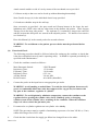
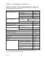
User Information Label (Table 1)
WARNING: All operators who are not medically qualified should receive full and
proper instruction from a qualified person, both on resuscitation and on detailed use of
the equipment in the particular situations in which it might be employed.
The ventiPAC may be used by fully trained personnel in life support in accordance with the
ILCOR 2000 guidelines. Basic information is provided on the control module (see Table 1
below).
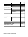
Table 1: ventiPAC 200D User Information Label
504-1117A
36
SECTION 5 : CARE, CLEANING, DISINFECTION & STERILISATION
(a)
Care
The ventiPAC ventilator is designed to operate in the face of the tough treatment it may
receive during its intended use but to prolong its life and retain its appearance basic care
should be taken in its cleaning and stowage between uses. In particular the following
steps are recommended to be taken after every use:(i)
Carefully inspect the complete system and make note of what actions
should be taken. In particular check for damage to hoses or masks, contamination
of any component, evidence of any part having been subjected to excessive force,
missing parts and gas cylinder contents.
(ii)
Clean or sterilise all parts, as necessary.
(iii)
Reassemble the system and carry out the functional check specified in
Section 3b.
(iv)
Stow the system in a clean area, or in its carrying case, away from heat and
intense light.
(b)
Cleaning
(i)
Control Module - The control module may only be cleaned by means of a
damp cloth. For obstinate marks a mild soap or non-abrasive cleaner may be used.
Wipe dry immediately with a soft clean cloth.
Do not attempt to sterilise the control module or to clean it by immersion in any
fluid.
Do not allow any oil or grease to come into contact with the module or, in
particular, with the input and output fittings because of the potential fire risk when
oxygen is being used.
(ii)
Patient valve - Disassemble the patient valve by unscrewing the two parts
of the body and carefully removing the yellow valve element, also the yellow
annular disc surrounding the patient connector.
Thoroughly clean each of the parts either in running hot water or in a detergent
solution followed by thorough rinsing under running water.
Scrub the rigid
plastic parts if necessary but not the yellow rubber parts.
Dry all the parts thoroughly and check them for damage before reassembly.
Ensure that the yellow valve element is inserted the correct way round and is not
distorted when the valve halves are re-screwed together.
(ii)
Hoses - The supply hose may be cleaned in the same manner as the control
module taking the same care to keep free from grease.
The patient hose may be cleaned in the same manner as the patient valve parts.
504-1117A
37
(c)
Disinfection
After cleaning, the patient valve components and the patient hose may be disinfected by
immersion in a cold solution of disinfectant or germicide. Rinse and carefully dry all
components before reassembly. Consult the manufacturer for any specific instructions.
The control module may be wiped with a disinfectant but it must not be immersed.
(d)
Sterilisation
CAUTION : To avoid damge to the EP circuit, detach all EP Circuit parts from the Patient
Hose prior to autoclaving. DO NOT autoclave EP Accessories.
The ventiPAC control module and non patient circuit accessories cannot be sterilised. The
components of the patient circuit may be steam sterilised after disassembly. Remove all EP
Circuit parts from the patient hose. The patient circuit can be treated up to 134°C. These
components may also be sterilised by gas sterilisation, following the manufacturer's
recommendations carefully.
The ventiPAC control module cannot be sterilised.
(e)
Reassembly and Function Testing
After cleaning or sterilisation, parts must be carefully dried and then reassembled.
Before putting the system back into service the functional check described in Section 3(b)
should be carried out.
504-1117A
38
SECTION 6 : MAINTENANACE
(a)
General
Because of the high reliability and long life of the control elements used, the ventiPAC
does not require any specific planned servicing. Service is only required if calibration
needs to be restored, if component failure occurs or if damage is incurred.
It is recommended that maintenance is carried out at two levels. At the first level, the
procedure specified in Section 3(b) should be followed at regular intervals, typically once
a month, irrespective of use, and a record kept by the use of the log sheet at the back of
this manual. At the second level, the performance of the ventilator should be checked as
specified in Section 6(b).
(b)
Performance Checking
Performance checking of the ventiPAC ventilator must be carried out with equipment
calibrated to ensure accuracy under the flow patterns generated by the machine. It should
be carried out by suitably trained personnel. If suitable personnel or equipment are not
available it should be checked by the Pneupac as part of a service contract or its authorised
representative.
Recommended performance checking procedures and suitable equipment are detailed in
the product maintenance manual which is available to suitably trained personnel.
The frequency of performance checking should be determined by the user depending upon
the intensity of use. Normally, this would be not more often than once every 6 months
but at least once every 2 years.
(c)
Changing of battery
The specified batteries will give several years of service under normal use conditions but
to avoid the need to locate a spare battery whilst the ventilator is in field service it is
recommended that the battery is replaced as a matter of routine at the same time as the
performance checking as specified in Section 6(b) above. (If the equipment is checked
every 6 months and the date of the battery changing is recorded, replacement is only
necessary every second check, i.e. annually). The procedure for changing the battery is as
follows (see section2(c) 15 for precautions in MRI use): (i)
Switch ventilator off by selecting 'Demand' on the main pneumatic switch.
(ii)
Remove the battery retaining cap, situated on the right hand side of the
control module, by twisting a quarter of a turn anti-clockwise using a coin
in the slot provided.
(iii)
The battery will be automatically pushed out of its holder.
(iv)
Fit the replacement battery, base first, into the holder. (The positive cap
must be showing outwards).
(v)
Replace the battery retaining cap by pushing it against the battery and
twisting clockwise until it stops after a ¼ turn. (The cap is reversible so
ensure that the marking on the outside of the cap corresponds to the battery
being used. See section 2(c) 15).
504-1117A
39
(vi)
Select 'CMV/Demand' on the main pneumatic switch and check that the
alarm system runs through the start-up self checking procedure (See section
3(b) 5).
If the battery failure alarm operates (indicated by a medium priority audible and visual
alarm) whilst ventilating a patient and it is considered necessary to maintain the electronic
monitoring then the above procedure should be followed but care should be taken to
minimise the time that ventilation is interrupted. It should be remembered that battery
failure does not affect the operation of the ventilation functions nor the effective operation
of the pneumatic alarms and safety devices.
(d)
Servicing
If the ventiPAC ventilator shows a malfunction during operation or testing or if its
performance is measured to be outside the tolerance stated in the specification (see Section
8(b) & (c)) during its performance checking, then the unit must be withdrawn from
operation and an appropriate service must be carried out.
Servicing or adjustment of the ventiPAC ventilator should only be carried out by
competent personnel who have been trained by the manufacturer for such work.
WARNING: Failure to use approved circuits and accessories may lead to
unsatisfactory ventilator performance.
WARNING: The ventiPAC ventilator is manufactured and ‘CE’ marked to the
requirements of 93/42/EEC. To ensure that this equipment functions as intended, use
only the manufacturer’s authorised spares.
504-1117A
40
SECTION 7 : ACCESSORIES and SPARE PARTS
WARNING: The ventiPAC ventilator is manufactured and ‘CE’ marked to the
requirements of 93/42/EEC. To ensure that this equipment functions as intended, use
only the manufacturer’s authorised spares.
Description
Airway, Guedel, Disposable
Battery, General Purpose
Order Code
Size 00 Paediatric
W6873/CE*
Size 0 Paediatric
W6874/CE*
Size 1 Child
W6875/CE*
Size 2 Adult
W6876/CE*
Size 3 Adult
W6877/CE*
(not for MRI use)
Type 123A 3V Lithium(widely
available camera battery)
MRI and General Purpose Use
W269-023
Battery Retaining Cap
510-A1845*
Case, carrying, comprehensive
A177/Z1/CE
+
Control Module
ventiPAC 200D
(MRI compatible as standard)
510A1956
Cylinder, Lightweight Aluminium
Comprehensive (full)
W6837/CE+
(empty)
W6838/CE+
Exhaust Collector 30mm Male
W7131/CE*
EP Patient Circuit Assembly
510A2338
Filter Assembly, EP sensing line
510A1768/CE*
Gauge, Cylinder Contents
W6829/CE
Harness, Clausen
W6871/CE*
Hook Ring
W6872/CE
Knapsack
W8654/CE
Hose, input 1.5 metres long
+
+
BS5682 Oxygen/G 1/4 (standard hose)
A4981/CE
BS5682 Air/G 1/4 (standard air hose)
A4982/CE
Open ended/G 1/4
A4983
DISS/DISS oxygen
A4984
DISS/DISS Air
A4985
DIN/DIN air/oxygen
A4986/CE
+
+
+
+
Parts marked (+) are available as MR Compatible variants. Add suffix /MRI to standard order code.
Parts marked (*) are completely non-magnetic as standard.
504-1117A
41
Description
Hose, input 1.5 metres long
Order Code
Mini Schrader oxygen/G 1/4
A4987
Mini Schrader air/G 1/4
A4988
Hoses up to maximum 15 metres available
Patient Hoses,:
1.2 metres long
W7130/CE*
Heavy Duty, 1.2 metres long
W7486/CE*
Hoses, Oxygen Therapy with BS5682 Probe ( 6 L/min flow)
A254/6/CE+
Lightstick -
Pack of 10
W6858/10/CE
Pack of 50
W6858/50/CE
Oxygen Therapy Disposable (Pack of 5)
A369/CE*
Adult Clear
W6807/CE*
Child/Small Adult Clear
W6806/CE*
Paediatric Size 1
W6804/CE*
Paediatric Size 0
W6803/CE*
Masks,
+
Mounting, Clamp for Medical Rail (30-35mm)
A4843/CE
Mounting, Clamp for Pole (12-26mm)
A4844/CE
Oxygen Therapy Unit with BS5682 Probe (6 L/min)
A253/6/CE+
Regulator, O2 Pin Index Cylinder
Outlet for BS5682 Probe
A162/CE
connection with:
Outlet for BS5682 Probe + variflow A162/Z43/CE
selector
+
Regulator, with Outlet for BS5682 DIN (O2)
A166/CE
O² Probe and cylinder connection:
A166/Z31/CE
Bullnose
Sensing Line (EP option)
W6832/1.6/CE*
Sling, Carrying
W7140/CE
User's Manual
504-1117A
Valve, Patient - for ventiPAC 200D
(V200D)
A4563/CE*
Valve, PEEP 0 – 20 x100Pa (0 - 20cmH2O)
W7139/CE+
Wheel, Valve, Cylinder
A171/CE
Washer, Pin Index Yoke (pack of 3)
276/3/CE
Parts marked (+) are available as MRI compatible variants. Add suffix /MRI to standard order code.
Parts marked (*) are completely non-magnetic as standard.
504-1117A
42
SECTION 8: TECHNICAL INFORMATION
(a)
Principles of Operation
The principles of operation of the ventilator are illustrated by the block diagram in figure
5. Compressed gas enters the ventilator from the input hose at the inlet connection 1 and
this is fed to the main pneumatic switch 3.
Figure 5: Principle of operation of the demand version of the ventiPAC ventilator
When this switch is open, supply gas flows to the pressure regulator 4 where it is regulated
to 2.75 bar before being fed to the main oscillator.
The oscillator is an integrated miniature pneumatic device which switches the flow on and
off at a frequency controlled by the setting of the precision needle valves 6 and feeds the
two coupled flow control needles 13 & 14.
If the 'Air Mix' mode is selected the switch 16 is in the off state and gas passes through
needle 13 to the nozzle of the entrainment device 15. Ambient air is entrained and drawn
in through port 19 via non-return valve 17 and the resultant gas mixture is fed to the
patient valve through the output connection 10. The flow of gas is controlled by the
setting of needle valve 13.
When the 'No Air Mix' mode is selected, switch 16 is open and driving gas can also pass
through needle valve 14 and into the entrainment port of 15. This valve is so adjusted that
its flow always matches the entrainment requirements of the mixing device and in this way
100% driving gas is fed to the patient.
The inspiratory and expiratory time control knobs are connected to needle valves 6 and
together control the cycling frequency of the oscillator. The inspiratory flow control knob
is connected to the coupled needles 13 and 14 to control the flow to the patient.
Inflation pressure is limited by the setting of the spring loaded variable relief valve and is
measured and displayed by the inflation pressure monitor.
During the expiratory phase the patient circuit is vented to atmosphere at 20 by means of
the normally open valve 18. In the event of supply gas failure this allows the patient to
breathe from the atmosphere without undue restriction. It also vents the patient circuit to
avoid patient valve lock-up due to trapped pressure.
504-1117A
43
Supply to the demand valve is taken directly from the inlet connection and its output is
connected to the output connection via non-return valve 9.
The demand detector is connected to the demand valve and automatically senses the
demand flow being taken by the patient whilst breathing spontaneously. It operates in
conjunction with the oscillator to integrate this signal and to extend the expiratory phase,
as a function of the spontaneous tidal volume, up to a maximum time dictated by the
frequency setting of the ventilator. Thus, if the patient demands a high flow for a short
duration or a low flow for a longer duration, for a similar level of tidal volumes, an equal
expiratory time will be allowed before the next ventilatory breath. The cumulative effect
of successive spontaneous breaths by the patient is that the ventilator appears to become
inhibited although in fact this is only on a breath by breath basis.
In order to avoid inhibition by weak breathing or panting, very low flows are ignored and
no action is taken in response to very short breaths.
Inhibition starts at 150 ml and increases to a full inhibition of 450 ml. The level of
spontaneous breathing required to fully inhibit the oscillator is fixed at that of a typical
adult . This is taken as a tidal volume of about 450 ml at 12 to 16 b/min.
Higher spontaneous ventilation rates can readily be taken and will result in complete
inhibition of the ventilator. Lower ventilation rates, as may be taken by a small adult or a
child, will only give partial inhibition but providing the demand flow is above 15 l/min the
ventilator will still interact with the patient and synchronise its ventilation pattern with the
spontaneous breathing.
When the main pneumatic switch is turned off the demand valve remains active whilst the
ventilator is connected to a gas supply. In this mode, therefore, the patient can be given
100% oxygen with the economy of use offered by a demand valve or the spontaneously
breathing patient can be largely protected from the effects of a non respirable or toxic
atmosphere.
The multifunction alarm built into the ventiPAC 200D ventilator is electrically powered by
a replaceable single cell lithium battery but the ventilatory functions of the ventiPAC
ventilators are completely independent of the alarm functions and its power source.
The alarm unit is microprocessor controlled and has four preset pressure level detectors
which monitor, respectively, the gas supply pressure, the inflation pressure, operation of
the pneumatic pressure relief valve and operation of the demand breathing detector.
The gas supply pressure detector is built into the pneumatically operated visual indicator
and is used to operate a medium priority audible alarm if the supply pressure drops to a
level where the indicator shows red.
The inflation pressure detector is a pressure switch which senses the pressure at the outlet
connector of the ventilator. An output signal is given to the alarm control unit whenever
the inflation pressure is greater that 10 x100Pa (10cmH2O). The signal is used to
determine if the pressure has passed through this threshold at least once in any 10 second
period. If not, an alarm is provided in order to warn either of inadequate inflation pressure
due to a leakage or failure to cycle or that the pressure is constantly above the threshold.
The relief valve detector is used to sense if gas is being vented from the patient circuit by
the variable relief valve at the pressure set by the relief pressure control.
504-1117A
44
The demand breathing detector is used to sense whenever the demand detector unit gives a
signal to the ventilator control unit causing it to interact with the patient’s breathing. The
signal is used to suppress the alarm in the same manner as the cycle detect signal. The
‘breathing detect’ visual indicator is operated to alert the operator that a spontaneous
breath has occurred and that the low pressure alarm has, therefore, been temporarily
inhibited.
The alarm unit is designed to operate from 3 volts and therefore only lithium batteries can
be used. Other batteries will fail to operate the alarm system.
504-1117A
45
(b)
Technical Data
Principle of operation: The ventilator is a time cycled, volume preset, pressure limited, flow
generator. It acts as a pressure generator at flow settings below 0.25 L/s with the 'Air Mix'
setting.
The ventiPAC 200D incorporates a patient demand valve and a ventilation inhibit function which
becomes operative when an adult patient breathes at an adequate level.
Power Source:
Gas specific terminal outlet providing dry, oil free, filtered gas within
the pressure range 305 to 600 kPa at 65 L/min. (This ensures a
minimum pressure of 280 kPa at the ventilator input ports with
allowance for supply hose pressure drop). As standard the ventilator is
calibrated for use with oxygen.
Frequency Range:
7 to 60 b/min
Flow Range:
6 to 60 L/min
Inspiratory Time Range:
3.0 to 0.5 seconds
Expiratory Time Range:
6.0 to 0.5 seconds
Flow Range:
0.1 to 1.0 L/sec (6 to 60 L/min)
Breathing parameters derived from control settings:
Tidal Volume:
3000 to 50ml
Minute Volume at I:E 1:2:
20 to 2 Litres
VBS:-
4.5 x100Pa (4.5cmH2O) at 60 L/min
Inspiratory Resistance:
3 x100Pa (3cmH2O) at 30 L/min
Expiratory Resistance:
3.5 x100Pa (3.5cmH2O) at 60 L/min
1.5 x100Pa (1.5cmH2O) at 30 L/min
Compliance:
12 mL/ kPa
Internal volume:
270 mL
I:E Ratio
Duration of Gas Supply:
Infinitely adjustable
1.
22 min/L cylinder capacity/200 x100kPa (200 bar) charging
pressure when set to deliver 9.6 L Minute Volume at 12
breaths/min delivering 100% O2 at an I:E ratio of 1:1.6.
This is equivalent to 52 minutes from a 2.7 L‘D’ size cylinder
2. 60 mins/L cylinder capacity/200 bar charging pressure when set to
deliver 9.6 L Minute Volume at 12 breaths/min at an I:E ratio of
1:1.6 with ‘Air Mix’ selected.
This is equivalent to 160 minutes from a 2.7 L‘D’ size cylinder
Relief Pressure Range:
20-80 x100Pa (20 to 80cmH2O *) accompanied by audible alarm.
Maximum Limited Pressure:
100 x100Pa (100cmH2O *)
Inflation Pressure Monitor:
Indicates from -10 to +100 x100Pa (-10 to + 100cmH2O *).
Sensing Line Filter
25mm dia. in-line hydrophobic filter, flow resistance <50 x 100Pa at 4
L/min, particle retention rating >99.999% DOP aerosol 0.3 - 0.4 µm
with face velocity 10 L/min
(EP option only):
Air Mix:
0 or 70% air mix, selectable, providing 100% or 45% O2 when using
oxygen as gas source.
* 1 x100Pa = 1.02 cmH2O (or 1 x100Pa = 1 cmH2O -2%)
504-1117A
46
Gas Consumption:
&
'No Air Mix' - V
DEL
plus 20 ml/cycle
&
'Air Mix' - 30% V
Demand Parameters, Demand Flow:
DEL plus 20 ml/cycle
commences at -2 x100Pa (2cmH²O)
100 L/min at -8 x100Pa (8cmH²O)
maximum > 120 L/min.
These demand sensitivities are with 400 kPa supply pressure.
Higher supply pressures will slightly decrease the sensitivities.
Output Connection:
22/15mm co-axial taper
Patient Circuit:
1.2m long, 15mm single bore polyester hose with autoclavable
patient valve.
Power Source:
Replaceable 3/3.6volt lithium battery. Two options:Size 123A for general use (widely available camera battery).
Size AA special low magnetic battery for MRI and general
use, Pneupac part number W269-023.
Battery Life:
Shelf life – 10 years. In general use – in excess of 1 year.
Supply Gas Input Connectors:
G 1/4 connection intended for the permanent connection of the
input hose.
Gas-specific connectors, for use with user
interchangeable hoses, are available if specified
Input Hoses, Standard:
1.5m long, 6mm bore with probe to BS 5682 oxygen as standard.
(Alternatives available).
Minimum demand to inhibit ventilator flow : 15 L/min
tidal volume : 450ml nominal at 12 b/min.
Low Pressure (Disconnect) Alarm:
An alarm signal is generated if patient pressure does not rise
through the low pressure setting of 10 x100Pa at least once in 10
seconds.
Alarm silenced:
Alarm silenced for 60 seconds duration - visually indicated
Dimensions:
Control Module: 92H x 220W x 162D mm
Dimensions
Instant Action Case:247mm H x 245mm W x 615mm L
Weight of Control Module:
3.1kg
Weight of Instant Action Case:
10 kg (complete with ventiPAC 200D and D sized cylinder (full))
Mounting Brackets Threaded Bushes: M5 x 1.0 x 7mm deep.
Autoclaving Temperatures:
Detachable breathing circuit components: maximum of 134°C
Weight of Patient Valve:
50g
Patents:
This product is covered by the following patents;
UK 2,174,760B , EP 0343818, EP 0343824 & EP 0342883
Standards:
EN794 Lung Ventilators - Part 3 Particular requirements for
Emergency and Transport Ventilators.
The unit follows the International Standard for alarm sounds and
indication: ISO 9703
Electrical Safety to IEC 601-1, Internally powered Type ‘B’
equipment. EMC to EN60601-1-2
* 1 x100Pa = 1.02 cmH2O (or 1 x100Pa = 1 cmH2O -2%)
(c)
Accuracies
The accuracies to which the ventilation parameters of the paraPAC ventilator are factory
calibrated and how these are affected by operating and ambient conditions are tabulated in
Appendix B.
504-1117A
47
(d)
Terms and Definitions
Airway Resistance:
Pressure drop across airway per unit flow.
AHA:
American Heart Association
CMV:
Controlled Mandatory Ventilation
CPR:
Cardiopulmonary Resuscitation. Comprehensive standards and guidelines for
this procedure are given by the American Heart Association in the Journal of the
American Medical Association (JAMA), 6th June 1986 Vol 255 No 21.
Demand Valve:
A valve which delivers gas to the patient at a flow related to the inspiratory
efforts of the patient
Expiratory Phase:
Interval from the start of expiratory flow to the start of inspiratory flow.
Expiratory Time (TE):
Duration of the expiratory phase.
FiO2:
The oxygen content of the gases inspired by the patient expressed as a fraction.
Frequency (f):
The number of ventilation cycles per minute (breaths/min).
Inspiratory Flow:
The flow delivered to the patient by the ventilator during the inspiratory phase.
Also see Minute Volume below.
Inspiratory Phase:
Interval from the start of inspiratory flow to the start of expiratory flow.
Inspiratory Time (TI):
Duration of the inspiratory phase.
I/E Ratio:
The ratio of the Inspiratory Time to the Expiratory Time.
JAMA
See CPR.
Lung Compliance:
Volume added per unit pressure increase when is added to a human or artificial
lung.
Maximum Patient
Inflation Pressure:
The maximum pressure that can be delivered by the ventilator to the patient.
Minute Volume
& DEL):
(V
Delivered Total Ventilation or the volume per minute of gas delivered through
the patient connection port during the inspiratory phases.
MRI:
Magnetic Resonance Imaging.
Mouth Pressure:
The patient inflation pressure as measured at the patient's mouth.
Patient Valve:
Valve that directs gas into the lungs during the inspiratory phase and allows
expiration to atmosphere during the expiratory phase.
PEEP Valve:
A valve which is attached to the exhalation port of the patient valve in order to
hold a positive expiration pressure at the patient's mouth at the end of the
expiratory phase. (Positive End Expiration Pressure - PEEP).
PEEP:
Positive End Expiratory Pressure. Pressure in the breathing circuit is
maintained at a set positive pressure throughout the expiratory phase.
Pressure Generator:
The ventilator delivers ventilation by establishing a constant set pressure at the
patient connection throughout the inspiratory phase. The resultant flow into the
lungs is determined by the compliance of the patient’s lungs and the resistance
of the airways.
Relief Valve:
Valve which limits the maximum patient inflation pressure by venting excess
gas to the atmosphere.
Tidal Volume (VTDEL):
Volume of gas delivered to the patient during an inspiration phase.
VBS:
Ventilator Breathing System. The breathing system connected to the patient
connection port and bounded by the exhaust port and the air entrainment device.
504-1117A
48
(e)
Explanation of Symbols and Alarm Condition Indicated
Inflating Gas Input Port Connector.
Compressed gas entering this port is delivered to the patient after its
pressure energy has been used to power the ventilator.
Gas Output Port Connector
The transPAC ventilator breathing system, supplied with the
ventilator, is attached to this connector to transfer ventilating gas
from the ventilator to the patient connection.
High Pressure Audible Alarm (Pneumatic)
Gas passes through the alarm whenever the pressure in the
ventilation breathing system exceeds the setting of the pressure
relief valve.
CPR Setting
This symbol indicates the settings that should be used in order to
perform cardiopulmonary resuscitation following AHA Guidelines.
O2
Qmax
Chemical symbol for oxygen
Maximum Flow Requirement
This symbol denotes the maximum flow requirement at the minimum
input pressure
Connection Points for EP Option
This symbol shows connection points for the external pressure
sensing line (See section 2(d)(i) 2 and Figure 1a.)
Supply Gas Failure Alarm
This symbol identifies the pneumatically operated supply-gas failure
visual alarm. Any visible red indicates a low supply pressure or a
restrictive supply. This is accompanied by a medium priority
audible alarm.
Type ‘B’ equipment defines the degree of electric shock regarding
allowable leakage currents
IEC 601-1
Internally Powered
Type B
Caution
Refer to User’s Manual before use
Audio Alarm Silenced Indicator
This orange light flashes once every 3 seconds during the 60 second
silenced period, to indicate that the electronic alarm is in its silenced
state.
Breathing Detect Indicator
This green light flashes for 1/10th second to indicate when a demand
breath has been registered by the demand detector within the
transPAC ventilator.
504-1117A
49
Low Battery Indicator
This yellow light indicates that battery voltage is low. Initially it
flashes every 10 seconds. This indicates that the battery is low
although monitoring will continue. The flashing rate increases to
twice every second, accompanied by a medium priority alarm, for
the final few minutes at the end of the battery life.
High Inflation Pressure Visual Alarm
This red light flashes at 2 times per second after the high pressure
relief valve has operated and whenever it is venting inflation gas to
the atmosphere. It is accompanied by a pneumatically generated
audible alarm. If the relief valve has operated for 3 successive
cycles, or for at least one second, then the high priority audible
alarm sounds and the visual alarm flashes continuously. Both
persist until 10 seconds after the condition is last detected. They
then automatically reset.
The same alarm signals are given if a continuous positive pressure
greater than 10 x100Pa is detected for 10 seconds or more.
Cycle Indicator
This green light flashes once, for 1/10th second, every time the
patient inflation pressure rises through the pre-set threshold pressure
of 10 x100Pa (10cmH2O). This indicates normal operation.
Low Pressure/Disconnect Visual Alarm
This yellow light flashes 30 times per minu‘e if 'cycle ’etec‘' or
'breathing ’etect' has not been activated for 10 seconds. It is
accompanied by a medium priority alarm.
(f)
Indicated Priority of Audible Alarm Sounds
High Priority
Medium Priority
504-1117A
Two bursts of five pulses of sound repeated at the rate of 6 times per
minute, while the alarm condition persists, in accordance with ISO 9703.
One burst of three pulses of sound repeated at the rate of 6 times per
minute for 60 seconds. During the next 60 seconds the rate increases
progressively to 12 times per minute.
50
(g)
MR Compatibility Tests
Although the ventiPAC 200D has been assessed to be MR Compatible under the
conditions specified in the labeling, the following detailed test information is
provided to assist the user in ensuring suitability of the device for their specific
environment with a minimum of additional testing.
Test information:
(i)
Equipment
All tests were carried out on a Bruker 3T actively shielded MRI system, with
internal gradient bore of 63cm diameter, situated in the Wolfson Brain Imaging
Centre, Cambridge, UK. The frequency of this machine is 125.5MHz.
A ventiPAC 200D was used as a representative test model for these type tests as it
uses magnetically identical parts to those of the devices covered by this manual.
The ventilator was set to operate ventilating a test lung with the relief valve and
high pressure alarms just operating at the end of the inspiratory phase. Inspiratory
and expiratory times, frequency and peak inflation pressure were continuously
monitored by remote measurement.
(ii)
Projectile Risk:
At no point along the axis of the magnetic field did the ventilator present a
projectile risk but for a distance of about 15 cm around the point of maximum field
gradient (430 G/cm, approx. 40cm inside the bore of the scanner), slight restraint
was necessary to prevent gentle sliding if the ventilator was rested directly on the
hard surface of the carriage.
(iii)
Ventilator performance tests:
The ventilator was set to a nominal 1100 VT and 20 bpm, providing a peak
inspiratory pressure of 41x 100Pa (41cmH2O). It was placed, in turn, at the
extreme outer edge of the table, at the mouth of the bore (168G/cm), at the point of
maximum magnetic field gradient (430G/cm, approx. 40cm in from the mouth of
the bore) and at the isocentre of the magnet (3 Tesla).
At no point could any change in the delivered ventilation be detected and the
electronic monitoring operated consistently. Trial circuit disconnections and
airway obstructions were always indicated correctly. A small reduction in the set
level of the inflation pressure relief valve was observed, the maximum change
being about 12% in the 3 Tesla field, but in normal use this valve will be set with
sufficient margin for this change not to affect the ventilation. Similarly the
inflation manometer deviated by up to 3 x100Pa (3cmH2O) at the position of
maximum field gradient. Neither of these deviations was evident at the intended
position of use – outside the bore of the magnet.
504-1117A
51
(iv)
Imaging Tests:
Imaging tests were performed using the body gradient set with either head or body
RF coils (transmit and receive). A tissue mimetic phantom was placed inside the
head RF coil to simulate a person’s head. This consisted of a Perspex cylinder
filled with a copper sulphate and salt solution to mimic the electrical properties of
the head.
(v)
Effect of switching gradients
A standard echo planar pulse sequence was run whilst the ventilator was at the
position of maximum gradient switching (1m from the magnetic isocentre). This
sequence was chosen for its high switching rates and values. The maximum
gradient value used at this position was +/- 13.3mT (566396Hz) (EPI alternates
from high positive gradient to high negative gradient in 452µs) giving a switching
rate of 29.43T/s (1253Hz/µs). This process is repeated after 214µs with the
polarity switching again. This was run continuously whilst observing the
ventilator. No effect due to magnetic field switching could be detected.
(vi)
Effect of RF fields
A standard inversion recovery spin echo sequence was run with the ventilator at the
edge of the RF coil. This sequence was chosen because of its high RF load
(0.4W/kg for the head coil and 0.82W/kg for the body coil). No effects were seen
due to interaction of the system RF with the ventilator.
(vii)
Image quality
A standard spin echo sequence (employing both transverse and coronal views) used
for daily quality assurance was used to test for any RF interference due to RF
emissions from the ventilator. No spikes in the images were observed, indicating
no RF interference. Placing the ventilator control module next to the phantom’s
edge did, as would be expected, cause a magnetic susceptibility artifact, due to the
presence of the metallic contents near the imaging volume. When the control
module was situated at the base of the head cradle, 21cm away from the phantom’s
edge, no RF interference or susceptibility artifact was observed.
504-1117A
52
APPENDIX A
Product Safety, Transportation and
Disposal of Recommended Batteries
504-1117A
53
Page Intentionally Blank
504-1117A
54
APPENDIX A : PRODUCT SAFETY, TRANSPORTATION AND
DISPOSAL OF RECOMMENDED BATTERIES
Lithium Batteries
Product Safety, Transportation and Disposal
PRECAUTIONS FOR HANDLING AND USE
Lithium battery cells as recommended for use with this device will provide long, reliable
and safe service when used correctly. To achieve optimum performance and trouble-free
operation, the following precautions should be observed.
ALWAYS take care to fit batteries correctly, observing the ‘plus’ and ‘minus’
signs on the battery and appliance.
ALWAYS replace batteries in your equipment with the type and size of battery
specified by the manufacturer.
ALWAYS remove dead batteries from equipment and all batteries from equipment
your know you are not going to use for a long time.
ALWAYS keep batteries away from small children. If swallowed seek medical
advice immediately and contact the subsidiary of the battery manufacturer in you
country.
NEVER deliberately short-circuit batteries.
NEVER take apart, crush, puncture or mutilate lithium batteries.
NEVER bring a damaged cell in contact with water. Lithium metal reacts
vigorously with water producing flammable hydrogen gas which can cause a fire.
PRECAUTIONS FOR STORAGE
Batteries should be stored at temperatures between 10°C and 25°C with relative humidity
not exceeding 65%. To maximise shelf life excessive temperature cycling and storage at
temperatures greater than 25°C should be avoided. Storage of lithium batteries at lower
temperatures is possible, providing care is taken in returning the batteries to room
temperature prior to use.
Store unused batteries in their packaging and keep away from metal objects which may
cause short-circuit resulting in possible leakage, or in extreme cases an explosion.
CHARGING
WARNING: Lithium batteries are of the primary type and are NOT designed to be
recharged. Attempts to recharge these batteries can lead to leakage and possibly an
explosion.
No responsibility is accepted by the manufacturer for injury or damage resulting from the
cells having been recharged or otherwise abused.
504-1117A
55
IF PART OR WHOLE OF THE BATTERY IS SWALLOWED
SEEK MEDICAL ADVICE IMMEDIATELY
Note: Lithium batteries are not subject to EC requirements on the classification,
packaging and labelling of dangerous substances or preparations (directives 67/548/EEC
and 88/379/EEC as amended).
TRANSPORTATION
AIR TRANSPORTATION
Lithium batteries are exempt from IATA/ICAO transport regulations under special
provision A45, provided that they meet criteria given below.
ROAD TRANSPORTATION
Lithium batteries are exempt from the ADR regulations under Marginal 2901a, provided
that they meet the criteria given below.
RAIL TRANSPORTATION
There are no special requirements for the transportation of lithium batteries under the RID
regulations.
SEA TRANSPORTATION
Lithium batteries are exempt from the IMDG code under the special provisions of Page
9033, provided that they meet the criteria given below.
CRITERIA FOR EXEMPTION OF LITHIUM BATTERIES FROM
TRANSPORTATION REGULATIONS.
1.
Each cell contains not more than 1 gram of lithium or lithium alloy.
2.
Each battery contains not more than an aggregate quantity of 2 grams of lithium or
lithium alloy.
3.
Cells are separated so as to prevent short-circuit.
4.
Batteries are separated so as to prevent short-circuit and are packed in strong
packaging, except when installed in electronic devices.
5.
If a battery contains more than 1 gram of lithium or lithium alloy, it does not
contain a liquid gas that is considered dangerous, unless the liquid or gas, if free,
would be completely absorbed or neutralised by other materials in the battery.
The lithium batteries recommended in this Manual are covered by this exemption from the
above international regulations. For restrictions applying to individual countries, the
relevant regulatory authority should be consulted.
504-1117A
56
REFERENCES
1.
Dangerous Goods Regulations. Montreal: International Air Transport Association,
1993.
2.
European Agreement Concerning the International Carriage of Dangerous Goods
by Road (ADR). 1993 Edition. London: HMSO, 1992.
3.
Regulations Concerning the International Carriage of Dangerous Goods by Rail
(RID). 1990 Edition. London: HMSO, 1989.
4.
International Maritime Dangerous Goods Code. London: International Maritime
Organisation, 1992.
DISPOSAL
DISPOSAL PROCEDURES
As they contain no mercury, lead or cadmium, the disposal of the lithium batteries
recommended in this manual is not regulated by European Community Directive
91/157/EEC on “Batteries and Accumulators Containing Certain Dangerous Substances”.
However, individual countries may also establish regulations that cover the disposal of
waste batteries. These may be more stringent that EC requirements. Thus, local
regulatory authorities should be contacted for their disposal guidelines.
In the absence of specific regulations or guidelines the following is recommended for the
disposal of lithium batteries.
Up to five lithium batteries can be disposed of with other general waste.
504-1117A
57
Page Intentionally Blank
504-1117A
58
APPENDIX B
Calibration Accuracies and Deviations due to Change in
Ambient Conditions
504-1117A
59
Page Intentionally Blank
504-1117A
60
APPENDIX B : CALIBRATION ACCURACIES AND DEVIATIONS DUE TO CHANGE IN AMBIENT CONDITIONS
WARNING: It is essential that, where this equipment is used in extreme environmental conditions outside those specified in this manual,
the operator must exercise particular patient vigilance, since although this may not lead to a safety hazard, performance will become
more uncertain as conditions become more extreme.
ventiPAC 200D
Deviations due to changes in ambient conditions
Parameter
Inspiration time
Expiration time
Flow
Relief Pressure
(NAM)
(AM)
(NAM)
(AM)
(NAM)
(AM)
(NAM)
(AM)
Inflation pressure monitor
Oxygen
concentration
(AM)
Ambient
temperature +40ºC
Ambient
temperature -10ºC
Ambient pressure
110kPa
Ambient pressure
70kPa
-5%
-6%
-9%
-9%
at local
at STP
temp
+4%
+11%
+1%
+1%
+22%
+20%
+19%
+18%
at local
at STP
temp
-22%
-29%
-5%
-4%
-4%
-5%
-6%
-6%
at local at STP
pressure
+2%
+10%
+7%
+7%
+7%
+9%
+23%
+23%
at local
at STP
pressure
-10%
-38%
-8%
-6%
<+2.5 x 100Pa
<-6 x 100Pa
<-3 x 100Pa
<+4 x 100Pa
<-1 x 100Pa
-1.5 x 100Pa
<-1 x 100Pa
0 % points
+10 % points
0 % points
Accuracies of Calibrated Controls
Factory Calibrated to Further Deviation before
within ±
re-calibration necessary
±10%*
or 0.1s
±8%*
±10% *
±5% *
±5% upto a maximum of
2 x 100Pa
<+1 x 100Pa
±15% upto a
maximum of
6 x 100Pa
±2 x 100Pa
+1 % points
+5/-1 %points
±1 %point
±8% of reading
Notes: Tolerances on the Tidal Volume (the nominal figures on the instruction label as detailed in Table 1 page 36) are a combination of TI and Flow. The Tidal Volume
delivered can be adjusted by trimming TI or Flow. If the Tidal Volume accuracy is important, it is recommended that this parameter is monitored independently
during use.
Volumes are quoted as measured at local conditions and at STP conditions of 20ºC, 101.3 kPa. Variations in Humidity do not cause deviations in performance.
AM refers to Air Mix setting. NAM refers to No Air Mix setting
* These parameters calibrated with 15 x100Pa (15cmH2O) backpressure at the patient connection.
504-1117A
61
ventiPAC
Mean inflation Pressure (x100Pa
or cmH2O)
Equivalent Peak Inflation Pressure
with 10% due to pressure drop in
airway (x100Pa or cmH2O)
Equivalent Peak Inflation Pressure
with 50% due to pressure drop in
airway (x100Pa or cmH2O)
With
“Air
Mix”
Selected
With
“No Air
Mix”
selected
504-1117A
0
5
10
15
20
25
30
60
0
9
18
27
36
45
55
110
0
7
13
20
27
33
40
80
Tidal Volume Setting
%∆
∆
VT
%O2
%∆
∆
VT
%O2
%∆
∆
VT
%O2
%∆
∆
VT
%O2
%∆
∆
VT
%O2
%∆
∆
VT
%O2
%∆
∆
VT
%O2
%∆
∆
VT
%O2
1.0
+4
45
+3
46
+2
47
0
47
-2
47
-4
48
-6
48
-12
51
0.75
+10
44
+6
45
+3
45
0
46
-2
47
-5
48
-8
49
-26
56
0.5
+20
45
+13
46
+7
47
0
48
-7
50
-14
52
-21
55
-66
97
0.25
+62
46
+40
48
+22
53
0
59
-22
68
-44
84
-58
100
-58
100
0.1
+97
46
+58
56
0
71
-46
100
-46
100
-46
100
-46
100
-46
100
MAX
0
100
-0.1
100
-0.2
100
-0.3
100
-0.4
100
-0.5
100
-0.5
100
-1
100
MIN
0
100
-1
100
-1.5
100
-2
100
-2.5
100
-3
100
-3.5
100
-7
100
62
ventiPAC
APPENDIX C
Cleaning and inspection record log check
504-1117A
63
Page Intentionally Blank
504-1117A
64
APPENDIX C : CLEANING AND INSPECTION RECORD LOG CHECK
Contents
Complete
504-1117A
Cleanliness
Checked
Functional
Performance
Check
(section 3 (b)
65
Cylinder
contents
Date
Signature
Comments
Page Intentionally Blank
504-1117A
66