1
IONIZATION SOLUTIONS
µWire AeroBar®
Model 5710
User’s Manual
About Simco-Ion
Simco-Ion develops, manufactures, and markets system solutions
to manage electrostatic charge. As the world's largest provider of
electrostatics management products and services, Simco-Ion
improves its customers' business results by providing a total
solution to their electrostatic discharge and electromagnetic
interference challenges. Simco-Ion Technology Group is a division
of Illinois Tool Works (ITW), located in Alameda, California. For
more information about Simco-Ion visit www.simco-ion.com or call
800-367-2452. Simco-Ion is ISO 9001 and ANSI ESD S20.20
certified.
© 2013 Simco-Ion
19-5710-M-01 Rev 3
Important Safety Information
Carefully read the following safety information before
installing or operating the equipment. Failure to follow
these safety warnings could result in damage to your
ionization system and/or voiding the product warranty.
avoid ionizer degradation, keep grounded objects away from
To
the corona wire and the ionized air stream that is produced by
the AeroBar.
avoid injury to one's self or the product, make sure all
To
mounting clips and brackets are connected to a low-impedance
earth ground.
not clean the unit while the unit is powered. Doing so may
Do
result in additional contamination and possible shock.
avoid personal injury or damage to the equipment, perform
To
only the maintenance described in this manual.
not use this product in hazardous or explosive environ Do
ments
19-5710-M-01 Rev 3
Contents
1 Description ......................................................................... 1
1.1 µWire AeroBar Model 5710 ..................................................................... 2
1.2 Identification............................................................................................. 3
1.3 Bar Lengths.............................................................................................. 4
1.4 Corona Wire Cartridge ............................................................................. 5
2 Installation ........................................................................... 7
2.1 Safety Information.................................................................................... 8
2.2 Installation Guidelines.............................................................................. 9
2.3 Mounting ............................................................................................... 10
2.4 Power Connection Options .................................................................... 11
2.5 Wiring Information ................................................................................. 15
2.6 Factory Monitoring System (FMS) ........................................................ 16
2.7 Gas Requirements ................................................................................. 18
3 Operation ........................................................................... 21
3.1 Settings .................................................................................................. 22
3.2 Handheld Terminal (HHT)...................................................................... 26
3.3 Alarms.................................................................................................... 31
3.4 Standby.................................................................................................. 33
3.5 Master/Slave .......................................................................................... 34
4 Maintenance ..................................................................... 37
4.1 Maintenance Considerations ................................................................. 38
4.2 Corona Wire Inspection & Cleaning....................................................... 39
4.3 Cleaning the Corona Wire Cartridge Assembly & Chassis .................... 40
4.4 Cartridge Insertion/Removal .................................................................. 42
5 Specifications................................................................... 45
5.1 Specifications......................................................................................... 46
5.2 Dimension Drawing................................................................................ 47
5.3 Wiring Options ....................................................................................... 48
5.4 Parts & Accessories............................................................................... 54
5.5 Factory Default Settings......................................................................... 57
6 Warranty & Service .......................................................... 59
19-5710-M-01 Rev 3
1
Description
1.1 µWire AeroBar Model 5710
1.2 Identification
1.3 Bar Lengths
1.4 Corona Wire Cartridge
19-5710-M-01 Rev 3
1
1.1 µWire AeroBar Model 5710
The 5710 AeroBar uses patented µPulse technology to meet the
performance, cleanliness, and low cleaning/maintenance
requirements of the flat panel display industry.
The 5710 AeroBar has the following unique features and benefits:
• Patented µPulse technology with high efficiency output
• Corona wire is utilized to provide a uniform ion distribution with
low field voltage
• Low swing voltage permitting close placement to work surfaces
• µPulse technology and wire emitters combine to provide long
maintenance cycles
This manual covers the installation, operation, and maintenance of
the 5710 AeroBar.
19-5710-M-01 Rev 3
2
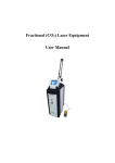
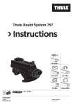
1.2 Identification
Figure 1. 5710 AeroBar Identification
Refer to Table 1 5710 AeroBar Lengths for AeroBar values of L1 and L2 for a particular bar length
19-5710-M-01 Rev 3
3
1.3 Bar Lengths
The 5710 AeroBar is available in multiple lengths to fit any tool
environment.
The 5710 AeroBar's active length (L1) should be equal or
greater than the length of the area to be ionized.
Bar Length
L1, mm
Bar Length
L2, mm
No. of 150 mm
Cartridges
No. of 250 mm
Cartridges
No. of
Mounting
Brackets
400
410
1
1
2
500
510
0
2
2
650
660
1
2
2
750
760
0
3
2
900
910
1
3
2
1000
1010
0
4
2
1150
1160
1
4
2
1250
1260
0
5
3
1400
1410
1
5
3
1500
1510
0
6
3
1650
1660
1
6
3
1750
1760
0
7
3
1900
1910
1
7
3
2000
2010
0
8
3
2150
2160
1
8
3
2250
2260
0
9
4
2400
2410
1
9
4
2500
2510
0
10
4
2650
2660
1
10
4
2750
2760
0
11
4
2900
2910
1
11
4
3000
3010
0
12
4
L1 = Nominal active length of bar. L2 = Nominal physical length of bar.
Table 1. 5710 AeroBar Lengths
19-5710-M-01 Rev 3
4
1.4 Corona Wire Cartridge
Configuration
There are two (2) 5710 AeroBar corona wire cartridges available, a
150 mm and a 250 mm. Both size cartridges share the same
attributes, except length. Any given 5710 AeroBar will consist of one
or more 250 mm cartridges and only one (1), if any, 150 mm
cartridges. Refer to Table 1 5710 AeroBar Lengths for cartridges
types in any particular 5710 AeroBar length.
Interchangeability
Cartridges of like sizes can be swapped with each other, or
swapped between 5710 AeroBars.
19-5710-M-01 Rev 3
5
19-5710-M-01 Rev 3
6
2
Installation
2.1 Safety Information
2.2 Installation Guidelines
2.3 Mounting
2.4 Power Connection Options
2.5 Wiring Information
2.6 Factory Monitoring System (FMS)
2.7 Gas Requirements
19-5710-M-01 Rev 3
7
2.1 Safety Information
Before installing or operating any component of the ionization
system, carefully read the following safety information:
To avoid injury to one's self or the product, make sure to use
the correct number of mounting clips for each bar. Refer to
Table 1 for how many are required.
To avoid injury to one's self or the product, do not place any
conductive labels on the 5710 AeroBar chassis! Conductive
labels may acquire an electrical charge over time and cause
random ESD events.
To avoid ionizer degradation, keep grounded objects away
from the corona wire and the ionized air stream that is
produced by the AeroBar.
To avoid injury to one's self or the product, make sure all
mounting clips and brackets are connected to a lowimpedance earth ground.
Do not clean corona wire while the unit is powered. Doing so
may result in additional contamination and possible shock.
To avoid personal injury or damage to the equipment,
perform only the maintenance described in this manual.
Do not use this product in hazardous or explosive
environments.
19-5710-M-01 Rev 3
8
2.2 Installation Guidelines
Keep in mind the following considerations when determining
locations for the 5710 AeroBars:
• Observe all site requirements and restrictions.
• Optimal performance will be obtained in an environment with
stable temperature and humidity levels.
• Use proper mounting brackets and hardware as required by
applicable building codes.
• Avoid installing the 5710 AeroBar near moving components or
surfaces.
• Do not install the 5710 AeroBar in hazardous or explosive
environments.
• The 5710 AeroBar should be mounted at least 150 mm (6
inches) away from any grounded painted surfaces.
To avoid injury to one's self or the product, do not place any
conductive labels on the 5710 AeroBar chassis! Conductive
labels may acquire an electrical charge over time and cause
random ESD events.
To avoid degraded ionizer performance, keep grounded
objects away from the corona wire and the ionized air stream
that is produced by the AeroBar.
19-5710-M-01 Rev 3
9
2.3 Mounting
The 5710 AeroBar has an integral rib molded along the top of its
chassis. Mounting brackets can be securely clamped to this rib.
Specially designed stainless steel mounting brackets are available
for the 5710 AeroBar and can be ordered from Simco-Ion. See
Section 5.4 Parts & Accessories in this manual.
Mounting brackets should be equally spaced along the length of the
bar. Refer to Table 1 5710 AeroBar Lengths for the recommended
number of brackets for secure mounting of each length of the 5710
AeroBar.
To avoid injury to one's self or the product, make sure all
mounting clips and brackets are connected to a lowimpedance earth ground.
19-5710-M-01 Rev 3
10
2.4 Power Connection Options
Electrical Wiring
Please refer to the diagrams below that show examples for possible
electrical wiring schemes.
A hand-held terminal (HHT) is required to set up the operating
parameters and to view the status codes of the 5710 AeroBar. To
avoid inadvertent alteration of the bar's settings, it is recommended
that the HHT be removed from the system when it is not required.
The HHT can access the RS-485 communication bus by being
connected to any of the RJ-11 Power/Communication cables in the
system
Daisy-chain Configuration
If desired, a maximum of three 5710 AeroBars may be electrically
connected together in a serial fashion ("daisy-chained"). Chaining
bars together can create a simpler electrical wiring scheme that
provides power and communication to all of the connected bars
through a single bus with only one connection required to an HHT
that can "talk" to all of the connected bars. Wiring connection is
made from the RJ-11 jacks on the sides of the bars that are labeled
"PWR/COM". See Section 5.3 Wiring Options for examples of
several wiring schemes.
A "daisy-chain" set up will typically consist of two or three bars that
are each addressed as "independent" bars. Each of the bars will
have a unique address and will maintain its own set of operating
parameters; the bars will share connection to +24 VDC power and
to the RS-485 communication lines (to a hand held terminal).
If there is an alarm condition at one of the daisy-chained bars, the
alarm will only be displayed on the status LEDs of the affected bar.
Daisy chain wiring does not provide global alarm monitoring
capability. See Section 2.6 Factory Monitoring System (FMS)
for more information regarding alarm monitoring.
19-5710-M-01 Rev 3
11
An individual connection to a CDA gas supply is required for
each bar. There is no "daisy-chain" provision provided for
connecting CDA between 5710 AeroBars.
Bars intended for use on a common wiring bus must be set for
unique addresses. See Section 3.2 Handheld Terminal, Bar
Address for information on how to set the address of a bar.
Independent bars must be set for the addresses 1, 2 or 3.
Duplicated bar addresses on a single bus will cause
communication errors! Please verify bar addresses to avoid
problems caused by duplicate addresses in a system.
Master/Slave Configuration
A pair of 5710 bars may be wired together in a master / slave setup.
This allows two bars to operate as a team and is typically used to
provide ionization coverage over a large, common target area. (By
contrast, a daisy-chain setup provides independent areas of
ionization that can each be set up differently.) Connection between
master and slave bars is made using a CAT-5 RJ-45 cable between
the RJ-45 jacks on the ends of the bars labeled "To Slave". See
Section 5.3 Wiring Options for examples of master/slave wiring.
This cable must be not longer than 3 meters in order to in
compliance with CE.
In a master/slave setup, timing oriented parameters will be
automatically copied from the master bar over to the slave bar to
keep the ionization generation/delivery between the bars
synchronized. However, power and balance settings will remain
settable independently at each of the bars.
A master-slave pair must be addressed "M" for the master bar and
"S" for the slave bar.
19-5710-M-01 Rev 3
12
A master/slave pair may also be daisy-chained with a single
independent bar. Note that a master-slave pair counts as two bars
of the maximum limit of three.
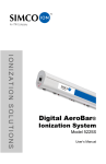
Power/Signal Distribution Box (optional)
An optional "Power Signal Distribution Box" is available for use
where a remote display of the bar's status indicator LEDs is desired
(see Section 5.4 Parts & Accessories). This box provides two RJ11 jacks for power/HHT connections, one terminal block for
connection to the FMS relay contact and standby request, and one
RJ-45 jack for connection to the "SBY/ALM I/O" connector on the
5710 bar.
A CAT-5 RJ-45 cable is required between the 5710 bar's "SBY/ALM
I/O" jack and the "AUX/ALARM" jack on the remote box. In a
master/slave setup, a single distribution box should be connected to
the master bar, not to the slave.
19-5710-M-01 Rev 3
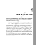
13
Figure 2. Power Connection using Power Signal Distribution Box
19-5710-M-01 Rev 3
14
2.5 Wiring Information
Primary electrical connection to the 5710 AeroBar is made through
the two RJ-11 jacks on the side of the bar that are labeled "PWR/
COM". These two jacks are wired in parallel and are functionally
interchangeable. Either of these RJ-11 jacks can be connected to
power or to a Handheld Terminal (HHT)
The 5710 AeroBar requires 24 VDC ±10%, 12W. max.
PIN
Description
1
24 VDC Input
2
Communications RS-485B
3
Power Ground
4
Power Ground
5
Communications RS-485A
6
24 VDC Input
Table 2. Power and Communication Connectors (PWR/COM RJ-11)
Typical cable used to connect to 24 VDC power or to a handheld
terminal is 26AWG 6-conductor modular flat cable terminated with
RJ-11 6/6 modular plugs.
CAT-5 RJ-45 cables are used between bars configured for a
master/slave setup.
19-5710-M-01 Rev 3
15
2.6 Factory Monitoring System (FMS)
The 5710 AeroBar provides for an Alarm output and a Standby
input.
The alarm output is across pins 1 and 8 of the bar's "SBY/ALM I/O"
RJ-45 connector and is a relay contact that is open when the 5710
AeroBar is either not powered or is in an alarm state (see Table 5
5710 AeroBar Alarm Codes for more information). The alarm relay
contact is rated for +/-24 VDC @ 0.2A maximum.
The standby input (active low) allows the user to temporally stop the
ion production without turning off the 5710 AeroBar. This is most
useful when the ionization needs to stop when there is no product
under the 5710 AeroBar, thus extending the maintenance interval
on the 5710 AeroBar. Standby is activated by pulling pin 3 of the
"SBY/ALM I/O" RJ-45 connector low. See Section 3.4 for more
information about Standby mode.
In addition, both the alarm output and standby input can be
conveniently accessed through a terminal block on the optional
Power-Signal Distribution Box. See Table 4 for pinout information
for this option.
Pin
Description
1
Alarm Contact 1
2
24 VDC Out
3
Standby Input (Active Low)
4
Signal Ground
5
Signal Ground
6
RESERVED
7
24 VDC Out
8
Alarm Contact 2
Table 3. 5710 AeroBar's "SBY/ALM I/O" RJ-45 Connector
19-5710-M-01 Rev 3
16
Pin
Description
1
24 VDC Out
2
Alarm Contact 1
3
Alarm Contact 2
4
Signal Ground
5
Standby Input (Active Low)
6
RESERVED
Table 4. ALARM OUTPUT Terminal Block, Optional Power Signal Distribution Box
19-5710-M-01 Rev 3
17
2.7 Gas Requirements
A flow meter is recommended for use in conjunction with gas
input to the 5710 AeroBar. The use of a flow meter will help
to establish a defined and uniform flow of air through the
ionizer.
Gas Requirements
Simco-Ion strongly recommends using clean dry air (CDA) to
improve performance of ion delivery to the target. A CDA supply
should be appropriately filtered to remove moisture, oil, and
particles. Filtration to the end user's desired cleanliness level is
recommended (filtration systems are not supplied by Simco-Ion.)
Using the 5710 without CDA will adversely affect decay times, as
well as allowing more buildup on the wire, necessitating more
frequent cleanings.
Gas Connections
The 5710 AeroBars have a quick push-connect gas inlet fitting on
one end of the bar.
Bars of length 400 mm to 1500 mm utilize a quick fitting that mates
with 6 mm O.D. tubing.
Bar of length 1650 mm to 3000 mm utilize a quick fitting that mates
with 8 mm O.D. tubing.
To connect the air supply tubing to the 5710 AeroBar:
• Insert the tubing into the gas quick fitting on the endcap. Be sure
the tubing is fully inserted by gently tugging back on the tubing
to lock the tube into place.
• To remove the tubing from the fitting, push in the fitting collar
towards the bar to release the tubing.
The amount of CDA required will be a function of many factors,
including the presence of airflow from HEPA filters, decay time and
19-5710-M-01 Rev 3
18
swing voltage requirements, and distance from the bar to the
product. Simco-Ion recommends a minimum of at least 6 liters/
minute flow for each 150 mm grill assembly on the bar and 10 liters/
minute flow for each 250 mm grill assembly on the bar. (See Table
1 for the number of each size grill assemblies on the bar.)
For example:
5710-500 mm = 20 liters/minute (total flow per bar)
5710-1500 mm = 60 liters/minute
5710-2150 mm = 86 liters/minute
More CDA than this may be necessary to meet a specific application
performance requirement. See Section 3.1 for more information on
the trade-off between CDA airflow and bar performance.
19-5710-M-01 Rev 3
19
19-5710-M-01 Rev 3
20
3
Operation
3.1 Settings
3.2 Handheld Terminal (HHT)
3.3 Alarms
3.4 Standby
3.5 Master/Slave
19-5710-M-01 Rev 3
21
3.1 Settings
The 5710 AeroBar comes from the factory with default settings that
can be optimized for a particular application. For best performance,
the settings should be tuned for your specific application--size of the
target, distance to the target, purging airflow, HEPA airflow, etc.
There are only four settings that need to be adjusted to optimize the
5710 AeroBar’s performance in your environment: Frequency,
Positive Power, Negative Power and Balance:
• Frequency: Sets the rate of positive and negative ions being
supplied to the target. A lower frequency will increase the swing
voltage present on the target. Conversely, a higher frequency
will decrease the swing voltage present on the target. Typically,
a lower frequency will reduce decay time as measured on a
CPM.
• Positive Power: Sets the amount of positive ions produced.
Increasing the Positive power level will produce more positive
ions, shift the ion balance in the positive direction and will
reduce the negative decay time.
• Negative Power: Sets the amount of negative ions produced.
Increasing the Negative power level will produce more negative
ions, shift the ion balance in the negative direction and will
reduce the positive decay time.
• Balance: Sets the ratio of positive and negative ions produced
for each cycle. Adjust the Balance value to coarsely adjust the
ion balance at the target. Then, use the Positive Power and/or
Negative Power settings to fine tune the ion balance at the
target.
Setup Guidelines
The 5710 AeroBar is designed for easy setup and calibration. In
order to obtain the optimum performance for your environment,
perform an initial setup with a charged plate monitor (CPM)
positioned at the targeted area under the ionizer. The Simco-Ion
Model 280A CPM is recommended.
19-5710-M-01 Rev 3
22
Below is list of guidelines to keep in mind when setting up the 5710
AeroBar:
• Lower the frequency and increase the voltage levels to reduce
ion recombination prior to the ions reaching the target.
• For small target areas that are close to the AeroBar (typically
within 50-150 mm to the bar), lower the ±power levels to reduce
the ion emission and use a higher frequency setting to
decrease the swing voltage.
• For long distance applications, a setup with lower frequencies is
appropriate.
• For short distance applications, a setup with higher frequencies
is appropriate.
• Adjust the balance to ensure that equal numbers of positive and
negative ions reach the target area
• Balance can be "fine-tuned" by using the Positive and Negative
Power setting.
Example of a Typical Setup
1. If the installation will be a multi-bar setup utilizing daisy-chained
wiring, it can be helpful to set the bar addresses before installing
the bars in place. See Section 3.2 Handheld Terminal, Bar
Address for information on how to change a bar's address.
(Addresses can be changed later but this requires disconnecting the bar from the bus so it can be communicated with
singly.)
2. Securely mount the bar (see Sections 2.2 and 2.3). Place a
Charged Plate Monitor (CPM) at the actual target location for
the ionized air stream.
3. Connect filtered CDA to the bar. (see Section 2.7)
4. Connect power to the bar. (see Sections 2.4 and 2.5)
The Model 5710 bar will be powered up as soon as 24 VDC
power is connected to the bar.
19-5710-M-01 Rev 3
23
Use either a wired connection to a Handheld Terminal (HHT)
or IR communication from a battery powered HHT to adjust the
bar's operating parameters.
5. Set the operating Frequency. Select the Frequency based on
the maximum +/- swing allowed at the target area.
Set the Frequency at the value that provides a +/- swing that is
as close as possible to the maximum limit allowed, but without
exceeding the limit.
6. Set both the Positive and Negative Power settings for a starting
value somewhere between 75-85%
7. Use the Pulse Balance screen of the HHT to adjust the Pulse
Balance value either more (+) or (-) to center the +/- swing
around zero.
8. If necessary, use the Positive Power and Negative Power
adjustments to increase or decrease the peak amount of +/swing.
9. If needed, adjust the Pulse Balance to re-center the +/- swing
around zero.
19-5710-M-01 Rev 3
24
The general performance of the 5710 AeroBar will be
determined by a number of factors:
• The bar's adjustable operating parameters set by the
end user
• The CDA flow rate through the ionizer. A higher CDA flow
rate generally means a faster CPM decay at the target.
• Any HEPA air flow rate in the target environment. Higher
environmental air flow from the bar to the target area
generally results in a faster CPM decay rate at the target.
• The proximity of nearby grounds. Grounded surfaces
near the ionizer or in the ionized air stream can cause
shifts in balance and/or slower decay times.
• The maintenance level of the bar's corona wire system. A
poorly maintained ionizer will result in reduced ionizer
performance for both decay times and balance.
19-5710-M-01 Rev 3
25
3.2 Handheld Terminal (HHT)
Use the Handheld Terminal (HHT) to change the settings of the
5710 AeroBar. The HHT can be used to monitor the 5710 AeroBar
during operation (It is recommended that the HHT be removed from
the system after setup to prevent inadvertent changes to the
operating parameters.)
The HHT has an LCD display, two LED
indicators, 5 menu navigation buttons, an IR
(infrared) Communications interface, two RJ11 ports, and a Power On/Off switch:
• LCD Display is where the setting and
5710 AeroBar information is displayed.
• COM/STATUS (Green) displays the
current HHT and Bar Status:
-
A flashing indicator indicates the HHT is communicating to
the 5710 AeroBar.
-
A solid on indicator indicates the bar is on and ionizing.
Fault (Red) displays fault at either the HHT or 5710 AeroBar:
• A flashing indicator indicates that the 5710 AeroBar and HHT
are not communicating.
• A solid on indicator indicates the 5710 AeroBar is in alarm or
standby and may not be ionizing. Some alarm states still allow
the bar to operate, see Table 5 Alarm Codes, for more
information.
Menu Navigation buttons allows the user view or set 5710
AeroBar parameter:
• <UP>/<Down> Arrows increment or decrement the parameter
value.
• <LEFT>/<RIGHT> Arrows navigate to screens menus.
• <ENTER> sends the parameter value shown on the “NEW” line
to the bar or performs the requested act.
19-5710-M-01 Rev 3
26
IR (infrared) Communications interface allows two
way line-of-sight communications to the 5710
AeroBar. A 9 VDC battery (internal) is required for
using the IR interface. When the HHT is turned on
and not wired to the 5710 AeroBar it will
automatically switch to IR mode. The IR range is
approximately 8 feet.
In IR Mode the HHT does not update automatically. To refresh
the screen, point the HHT at the 5710 AeroBar and press the
<ENTER> key.
In wired Mode the HHT updates automatically.
Two RJ-11 ports on the bottom of the HHT allow for
power and communication connections to a 5710
AeroBar over a wired RS-485 balanced pair serial
interface.
Power ON/OFF switch allows the user to turn on or off the HHT. In
the IR mode it is best to turn off the HHT when not in use to
conserve battery power.
BAR ADDRESS shows or sets the 5710 AeroBar’s communication
address. In order to set a bar's operating parameters, the HHT
needs to be set to the desired 5710 AeroBar’s address.
• Press the <Up> or <Down> Arrow to select a different 5710
AeroBar address.
While on this menu screen and the 5710 AeroBar's address
matches the address shown on the display, all three of the
LEDs on the 5710 AeroBar will quickly blink. This allows you to
locate the bar that is being addressed. The HHT cannot be
used in IR mode to change a bar's address setting.
19-5710-M-01 Rev 3
27
BAR ADDRESS
VERI FY
>
FLASHI NG LEDS <
ADDRESS = 0
0
CHANGE ADDRESS
Address type
>
<
NEW:
0
0
SET:
0
To Change the address of the bar, press and hold
the <Enter> key for about 5 seconds to activate a
"CHANGE ADDRESS" menu screen. Using this
screen, an address of 1, 2 or 3 can be set.
Addresses 1, 2 and 3 are used to denote
"independent" bars that will each operate as standalone units.
A pair of 5710 AeroBars can be set to work together
in a "master" and "slave" configuration. In this case,
set the address to "M" for the master and "S" for the
slave (see Section 3.5 Master/Slave for more
information).
SYSTEM STATUS shows the current status of the 5710 AeroBar:
SYSTEM STATUS
I ONI ZATI ON: ON >
ALM CODE: x x <
0
“Ionization” is a short notification of the 5710
AeroBar’s state and will display:
• “ON” when Ionization is normal;
• “SB” when the 5710 AeroBar is in standby;
• “TS” when the 5710 AeroBar is in Alarm Test;
or
• “AL” when the 5710 AeroBar has some type of
Alarm.
“ALM Code” will help diagnose any problems that
might occur. All states of the 5710 AeroBar
including a normal state have an associated
number code (see Table 5 5710 AeroBar Alarm
Codes) to aid in diagnosing any alarms that might
occur.
FREQUENCY shows or sets the 5710 AeroBar’s ionization cycle
rate which is the
FREQUENCY
>
NEW: XXX HZ <
SET: XXX HZ 0
19-5710-M-01 Rev 3
rate at which the ionization changes polarity. By
using the <UP> or <Down> arrow keys, you can
change the rate at which the ionization polarity
changes from 0.1Hz to 35Hz. After the value is
keyed in, press the <ENTER> key to save the new
value in the 5710 AeroBar.
28
POSITIVE POWER shows or sets the 5710 AeroBar’s positive
ionization output level.
POSI TI VE POWER
>
<
NEW: XXX
SET: XXX
0
Setting a larger value will increase positive ion
production and shift the ion balance in the positive
direction. By using the <UP> or <Down> arrow keys
you can change the positive ionization level from 1,
the minimum power level, to 100, the maximum
power level.
NEGATIVE POWER shows or sets the 5710 AeroBar’s negative
ionization output level.
NEGATI VE POWER
>
NEW: XXX
<
SET: XXX
0
Setting a larger value will increase negative ion
production and shift the ion balance in the negative
direction. By using the <UP> or <Down> arrow keys
you can change the negative ionization level from 1,
the minimum power level, to 100, the maximum
power level.
STANDBY shows or sets the 5710 AeroBar’s Standby mode.
STANDBY
NEW:
SET:
OFF
OFF
>
<
0
Setting the standby to "ON" will temporarily pause
the ionization of the 5710 AeroBar. This state will
also be shown in the SYSTEM STATUS screen as
"SB" with an alarm code of 4.
This screen will also show the state of the standby
input request from the RJ-45 "SBY/ALM I/O" port.
Note that a standby request from the RJ-45 port will
override a standby request set using the HHT.
ALARM TEST activates or deactivates the alarm output.
ALARM TEST
PRESS ENTER >
<
TO START
0
ALARM TEST
PRESS ENTER >
TO STOP
<
0
19-5710-M-01 Rev 3
On this screen you can turn on or off the alarm
circuit to test FMS connection to your equipment.
Pressing the <Enter> key will activate the alarm
output relay and show a walking (
) LED
display on the 5710 AeroBar. To stop the Test
simply press the <Enter> key again.
29
This state will also be shown in the SYSTEM STATUS screen as
"TS" with an alarm code of 11.
The Alarm Test will not change the 5710 AeroBar's ion
production. If the ionizer HV is enabled when the Alarm Test is
activated, the HV remains enabled during this test.
LOAD DEFAULTS to restore a set settings.
LOAD
DEFAULTS
>
SETTI NGS
<
PRESS ENTER 0
LOAD
ARE YOU SURE? >
PRESS ENTER <
TO CANCEL 0
Each 5710 AeroBar contains pre-defined settings
that can be recalled to return the 5710 AeroBar to a
known operational state.
Upon pressing the <Enter> key, you must confirm
this request. Using the <Up> or <Down> arrow
keys, select either CANCEL (default) or ACCEPT
then press <Enter>.
• Selecting ACCEPT will change all the 5710
AeroBar's settings to the pre-defined values
(except the 5710 AeroBar's address).
• Selecting CANCEL will return you the
previous menu screen.
DEFAULT
SETTI NGS
RESTORED
>
<
0
After selecting "ACCEPT", the HHT will display
"Default Settings Restored" for 2 seconds. The
restored settings will take effect immediately.
FIRMWARE VERSION shows the versions of both the 5710
AeroBar and HHT.
FW VERSI ON
5700 : X. Y
5710 : N. M
19-5710-M-01 Rev 3
>
<
0
Displays the firmware version of the addressed
AeroBar (Model 5710) and of the Handheld
Terminal (HHT, Model 5700).
30
3.3 Alarms
An alarm condition is indicated by the 5710 AeroBar's LEDs and the
HHT's red LED (if connected). Alarms are caused by one or more of
the following possible conditions:
Code
Grn
LED
Yel
LED
Red
LED
Alarm
Contacts
Comments
xx
OPEN
No Power
1
CLOSED
Normal, All OK
2
CLOSED
Wire Communication
3
CLOSED
IR Communication
4
CLOSED
Standby Mode
5
OPEN
Input Power Warning
6
OPEN
Local Power Supply Fault
7
OPEN
SLAVE Reporting Fault
8
OPEN
ARC Detected1
9
OPEN
Broken Wire Detected
10
OPEN
SLAVE Sync Failure
11
OPEN
Alarm Test
Off:
On:
Blink:
Walking:
_______________
1. When an ARC is detected, the AeroBar's high voltage will turn off for 30 second after which the
high voltage will turn back on and the AeroBar will resume operation.
Table 5. 5710 AeroBar Alarm Codes
For safety, the 5710 AeroBar is designed to shut off the high
voltage ionization any time an arc is detected in the area of the
corona wire. This alarm is indicated by a steady Green and
Red LED and an Alarm state 8.
Status codes reported for a bar that is addressed "S" (slave) will be
the standard code value plus 20. For example, an arc-event alarm
at a slave bar will be reported as an alarm code "28" rather than the
standard "8".
19-5710-M-01 Rev 3
31
To restore bar operation after a HV shutdown due to an arc
event, cycle the 24VDC power to the bar.
If the red alarm LED continues to stay lit, contact Simco-Ion
Technical Support (techsupport@simco-ion.com or 510-217-0460).
Alarm Test (for wiring testing, etc.)
The alarm output can be tested without affecting the ionization
output. Connect the HHT to the Ionizer (refer to Section 2.4 for
more information on connecting the HHT to the 5710 AeroBar.)
ALARM TEST
PRESS ENTER >
<
TO START
0
Navigate to the Alarm Test Screen, press the
<Enter> key on the HHT to start the alarm test.
This will open the Alarm relay contacts, simulating an alarm condition.
ALARM TEST
PRESS ENTER >
TO STOP
<
0
19-5710-M-01 Rev 3
To stop the test and return to normal operation,
press the <Enter> key on the HHT again.
32
3.4 Standby
Standby allows stopping the flow of ions while keeping the 5710
AeroBar’s electronics powered on. This mode can be used to
temporally turn off ionization when there is no product under the bar,
thus reducing the contamination build up on the wire.
The 5710 AeroBar can be place in standby mode by:
• Connecting signal ground to the Standby input on either the
bar's RJ-45 FMS I/O pin 5 or to Pin 3 of the optional Power/
Signal Distribution Box.
• On the HHT, navigate to the Standby screen,
and press the up or down arrow keys +
<ENTER> to set the 5710 AeroBar into
standby ("ON") or normal operation ("OFF").
STANDBY
NEW:
SET:
OFF
OFF
>
<
0
A standby request via the bar's "SBY/ALM I/O" connector or
from a Power/Signal Distribution Box will override a standby
request made via a HHT.
A master/slave setup, the standby request should be made to
the master bar if it is desired to have both bars go into standby.
A standby request made to a slave bar will only be applied to
the slave bar and NOT to the master bar.
19-5710-M-01 Rev 3
33
3.5 Master/Slave
In the case where two 5710 AeroBars are required to provide
ionization coverage of a common area, two 5710 AeroBars can be
connected together in a Master/Slave relationship. In a master/
slave setup, timing oriented parameters (operating frequency and a
sync signal) will be automatically copied from the master bar over to
the slave bar to keep the ionization generation/delivery between the
bars synchronized. However, power and balance settings may be
set independently at each of the bars.
To configure two 5710 AeroBars into one master and one slave,
simply address one bar as "M" for the master and the other as "S"
for the slave. Refer to Section 3.2 Handheld Terminal (HHT) BAR
ADDRESS for information on setting an 5710 AeroBar's address.
Use CAT-5 cable to connect from the master bar's "Slave RJ-45"
endcap jack to the "Slave RJ-45" endcap jack on the slave bar. This
CAT-5 cable will provide power, communication and sync signal
information from the master to the slave bar.
Figure 4. Typical Master/Slave Connection
To adjust the 5710 AeroBars, connect the HHT to the designated
Master 5710 AeroBar (or, in IR mode, point the HHT at the
designated Master).
Adjust the Master bar's operating parameters as you would for a
single, independent 5710 AeroBar (refer to Section 3.1 "Example
of a typical setup" for information on how to setup the operating
19-5710-M-01 Rev 3
34
parameters of an ionizing bar system.) The frequency setting of the
Master bar will automatically be copied and sent to the slave 5710
AeroBar. After setting up the master bar, proceed to set up the
operating parameters for the slave bar.
Master/Slave Issues
If a master bar is placed into "Standby", the slave bar will also go
into standby mode. However, if a slave bar is placed into standby,
the master bar will NOT enter standby mode.
If an alarm occurs at a master bar, the alarm will only be reported
and displayed at the master bar. If an alarm occurs at a slave bar,
the alarm state will be visually displayed via LEDs at both the
master and slave bar; however, the alarm status code reported by
the HHT will be the standard status code value plus 20. For
example, a master bar will report an arc-event alarm as a status
code "8" while a slave bar will report a status code "28".
A bar that is addressed as a "master" must be connected to a bar
addressed as a "slave" or an alarm (status code 10) will be enabled.
(Likewise, a slave bar will alarm unless connected to a master.)
The Master/Slave interconnecting cable must be not longer
than 3 meters in order to remain in compliance to CE.
If CDA purge gas is required for the master-slave bar
operation, the CDA must be supplied individually to each of the
bars. There is no provision for making a single gas connection
that runs between bars.
If the master-slave combination uses a long bar (>1500 mm) and a
short bar (<1500 mm), be aware of the difference in air fitting sizes
(6 mm vs. 8 mm) between short and long bars as explained in
Section 2.7 Gas Requirements.
19-5710-M-01 Rev 3
35
19-5710-M-01 Rev 3
36
4
Maintenance
4.1 Maintenance Considerations
4.2 Corona Wire Inspection & Cleaning
4.3 Cleaning the Corona Wire Cartridge Assembly
& Chassis
4.4 Cartridge Insertion/Removal
19-5710-M-01 Rev 3
37
4.1 Maintenance Considerations
As maintenance schedules will vary depending on installation
conditions, the end user will need to develop a schedule that meets
the requirements for their application. In general, equipment should
be checked on a monthly basis to ensure it is operating as originally
set.
There are no user-serviceable parts inside the 5710 AeroBar.
Any unauthorized service will void the warranty and may result
in additional repair charges.
19-5710-M-01 Rev 3
38
4.2 Corona Wire Inspection & Cleaning
Remove power from the 5710 AeroBar before inspecting or
cleaning the unit.
Do not clean the AeroBar while the unit is powered on. Doing
so may result in particle contamination to the work area and
possible shock.
Inspection
Before performing any maintenance, the 5710 AeroBar must be
powered down.
Dirty or eroded corona wires may result in reduced ionization output
or failure. Contamination can be caused by a number of
environmental factors, including non-visible airborne molecular
contaminates (AMC). The corona wire should be checked regularly
for erosion or material accumulating in or around the corona wire
and cartridge.
Cleaning the Corona Wire Materials
Remove power from the 5710 AeroBar before performing any
cleaning operations on the bar.
Cleaning is recommended every 6 months
or longer depending on the application
and/or environment.
Simco-Ion offers a specially designed 5710
AeroBar emitter wire cleaning tool. The
tool will conveniently and safely clean the
emitter wire using Simco-Ion self contained
emitter cleaner. See Section 5.4 Parts and Accessories for part
numbers of the 5710 AeroBar Cleaning Tool, Tool Extension Rod
and Emitter Cleaner.
19-5710-M-01 Rev 3
39
4.3 Cleaning the Corona Wire Cartridge
Assembly & Chassis
Remove power from the 5710 AeroBar before inspecting or
cleaning the unit.
Do not clean the AeroBar while the unit is powered on. Doing
so may result in particle contamination to the work area and
possible shock.
Use only 50% de-ionized water and 50% IPA to clean the
exterior of the 5710 AeroBar chassis and corona wire cartridge
grills. Do not use any other cleaners or solvents.
The external surfaces of both the 5710 AeroBar chassis and the
corona wire Cartridge grill assembly can be cleaned if dirt has
accumulated on the surface. Use a cleanroom-compatible cloth
moistened with 50% de-ionized water and 50% IPA. Do not use a
soaking wet cloth; the cleaning cloth should only be moistened with
IPA. Change the cloth frequently to ensure that any dirt is
completely removed from the surface to be cleaned. Do not use this
method to clean the corona wire inside a cartridge assembly. Use
the recommended Wire Cleaner tool that is described in Section
4.2. After cleaning, allow the bar to dry thoroughly before reapplying
power to the bar.
The corona wire cartridge assembly may be cleaned in an ultrasonic
bath using deionized water @ 50°C, maximum.
DO NOT ALLOW THE CORONA WIRES TO BE TOUCHED
DURING THE WASHING PROCESS.
Care must be taken while loading or removing the corona wire
cartridges from the ultrasonic bath.
19-5710-M-01 Rev 3
40
Cartridges must be loaded into the ultrasonic bath in either a single
layer or stacked in a crossed pattern to prevent tangling of the
cartridges and damage to the corona wires.
After washing, the cartridges must be completely dry before
reinstalling into the bar. The temperature of the drying operation
should not exceed 50°C, maximum.
19-5710-M-01 Rev 3
41
4.4 Cartridge Insertion/Removal
Remove power from the 5710 AeroBar before inspecting,
removing or installing any corona wire cartridges to the bar.
Failure to do so may result in particle contamination to the
work area and possible shock.
Remove power to the 5710 AeroBar before touching the corona
wire cartridges.
Squeeze the release tabs inward on either side of one end of the
cartridge and gently pull the end of the cartridge away from the clear
retaining clip, angling the cartridge away from the bar. If the other
end of the cartridge does not release from its retaining clip as the
cartridge angles away, squeeze the release tabs on that clip and
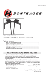
gently pull the cartridge out.
Figure 5. Location of Cartridge Release Tabs on Retaining Clips (top view)
Figure 6. Lift/Pull Cartridge Out of Retaining Clips (side view)
19-5710-M-01 Rev 3
42
To insert a cartridge, align the cartridge in between the
clear retaining clips and gently press the cartridge
toward the 5710 AeroBar, The retaining clips should click
into place when the cartridge is completely seated. The
base plate of the cartridge should be flat against the bar.
Replacement Cartridges
Replacements cartridge assemblies can be ordered from SimcoIon. See Section 5.4 Parts and Accessories for further
information.
19-5710-M-01 Rev 3
43
19-5710-M-01 Rev 3
44
5
Specifications
5.1 Specifications
5.2 Dimension Drawing
5.3 Wiring Options
5.4 Parts & Accessories
5.5 Factory Default Settings
19-5710-M-01 Rev 3
45
5.1 Specifications
Input Voltage
24 VDC ±10%, 12W (max)
Output Voltage
Adjustable, 13 kV pk-pk (typ)
Range
50-2000 mm, application and performance specification dependent
Frequency
Default setting at 1 Hz, adjustable from 0.1-35 Hz
Balance
Inherently self-balancing system <±25V over the length of the bar; maintains
balance performance >6 months without cleaning (in an ISO 14644-1 Class
4 or better environment)
Ion Emission
Micropulsed high voltage technology
Performance
3.5 sec decay average @ 600 mm (typ) measured at 5710 AeroBar center,
70 l/m purging air, no laminar flow; setting 1 Hz, 100% output, CPM: balance
<±10V; swing 100V pk-pk
Corona Wire
Tungsten, 100 micron dia.
Gas Supply
Clean dry air (CDA)
Airflow
50 psi (optimal); 90 psi (max) through 6 mm O.D. quick fitting (400-1500 mm
bars) or 8 mm O.D. quick fitting (1650-3000 mm bars)
Alarm Output
Relay contact, rated ±24 VDC @ 0.2A
Cleanroom Class ISO 14644-1 Class 2 (better than Fed. Std. 209E Class 1)
Operating Env.
Temperature 15-35°C (59-95°F); humidity 30-60% RH, non-condensing
Ozone
<0.05 ppm
EMI
Below background level
Bar Settings
All operating parameters set via a Handheld Terminal (HHT) by either wired
connection to the bar or by battery powered IR control
LED Indicators
Green POWER; Yellow COMMUNICATION; Red ALARM (combinations of
LEDs indicate specific status conditions of the bar)
Enclosure
ABS chassis; stainless steel reference plates
Dimensions
3.3H x 1.3W x 15.75/19.7/25.6/29.5/35.4/39.4/45.3/49.2/55.1/59.1/65/68.9/
74.8/78.75/84.65/88.6/94.5/98.4/104.3/108.25/114.15/118.1L in. (84H x 33W
x 400/500/650/750/900/1000/1150/1250/1400/1500/1650/1750/1900/2000/
2150/2250/2400/2500/2650/2750/2900/3000L mm)
Warranty
Two year warranty
Certifications
19-5710-M-01 Rev 3
RoHS 2 Compliant, KCC
46
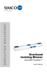
5.2 Dimension Drawing
Figure 7. 5710 AeroBar Dimension Drawing
Refer to Table 1 5710 AeroBar Lengths for 5710 AeroBar values of L1 and L2 for a particular bar
length
19-5710-M-01 Rev 3
47
5.3 Wiring Options
19-5710-M-01 Rev 3
48
19-5710-M-01 Rev 3
49
19-5710-M-01 Rev 3
50
19-5710-M-01 Rev 3
51
19-5710-M-01 Rev 3
52
19-5710-M-01 Rev 3
53
5.4 Parts & Accessories
33-2840-01
Cartridge, 150 mm
33-2850-01
Cartridge, 250 mm
33-1710-7 (7 ft)
33-1710-10 (10 ft)
33-1710-15 (15 ft)
33-1710-20 (20 ft)
33-1710-40 (40 ft)
RJ-11 6 pin, 6 wire Power and
communication cable
25-0540-6 (6 ft)
25-0540-10 (10 ft)
25-0540-15 (15 ft)
CAT-5 with RJ-45 Ethernet Cable
for connection to Power Signal
Distribution Box or Master/Slave
connection
33-5700-01
Power Signal Distribution Box
19-5710-M-01 Rev 3
54
32-2211-01
Swivel Mounting Bracket
32-2213
Mounting Bracket
33-5701-1
24 VDC Power Supply
91-5700-HHT-01
Handheld Terminal (HHT)
91-5700-01
Emitter Wire Cleaner 3 ft. Rod (must
order 22-1000)
33-5715-01
Emitter Wire Cleaner 3 ft extension
rod
19-5710-M-01 Rev 3
55
22-1000
19-5710-M-01 Rev 3
Emitter Cleaner (box of 50)
56
5.5 Factory Default Settings
The 5710 AeroBar will ship from the factory with the following
factory default operating settings. If custom defined default settings
are required, please contact Simco-Ion for further information prior
to ordering.
Bar Address:
Frequency:
Positive Power:
Negative Power:
Pulse Balance:
Standby:
19-5710-M-01 Rev 3
1 (Independent mode)
1 Hz
50
50
0
OFF
57
19-5710-M-01 Rev 3
58
6
Warranty & Service
Simco-Ion provides a limited warranty for the µWire AeroBar Model
5710. New products manufactured or sold by Simco-Ion are
guaranteed to be free from defects in material or workmanship for a
period of two (2) years from date of initial shipment. Simco-Ion
liability under its new product warranty is limited to servicing
(evaluating, repairing, or replacing) any unit returned to Simco-Ion
that has not been subjected to misuse, neglect, lack of routine
maintenance, repair, alteration, or accident. In no event is SimcoIon liable for collateral or consequential damages. Consumable
items such as, but not exclusive to, emitter points, corona wires,
batteries, filters, fuses or light bulbs are only covered under this
warranty if found defective as received with the new product.
To obtain service under this warranty, please contact Simco-Ion
Technical Support at techsupport@simco-ion.com or (510) 2170470.
19-5710-M-01 Rev 3
59
Notes
19-5710-M-01 Rev 3
60
Notes
19-5710-M-01 Rev 3
61
Technology Group
1750 North Loop Rd., Ste 100
Alameda, CA USA 94502
Tel: 510-217-0600
Fax: 510-217-0484
Toll free: 800-367-2452
Sales services: 510-217-0460
Tech support: 510-217-0470
ioninfo@simco-ion.com
salesservices@simco-ion.com
techsupport@simco-ion.com
service@simco-ion.com
www.simco-ion.com
19-5710-M-01 Rev 3