1
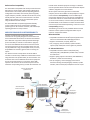
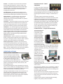
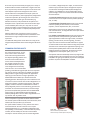
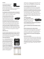
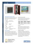
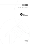
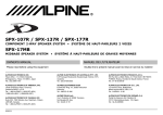
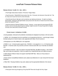
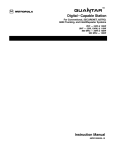
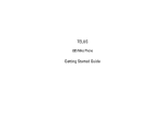
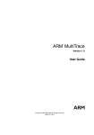
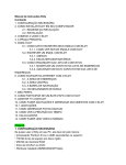
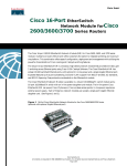
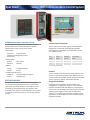
Spec Sheet Series 4000 Communications Control System Model 4020 CCU COMMUNICATIONS CONTROL SYSTEM The Series 4000 is a programmable, multichannel, multiposition radio control console featuring three operator position styles to meet a variety of user needs. • Public Safety • Police/Fire • EMS/Ambulance Integrator RD Model 4048 CCU Common Control Units (CCU) The CCU is the central “switch” that routes audio between radio/phone channels and console operating positions. Series 4000 CCUs are available in two capacities to match your application needs. • EOC/Disaster Management Centers • Government • Transportation • Aviation • Mass Transit • Maritime • Railways • Energy • Fresh/Waste Water • Oil/Gas • Electric • Facilities Safety & Security Channel Capacity Operating Positions Cross Channel Patches 4020 20 6 8 4048 48 16* 24 *15 with patch card installed • Utilities CCU Model • Healthcare • Corporate/College Campuses • Casinos • Hotels/Resorts SYSTEM OVERVIEW The Zetron Series 4000 Communications Control System is a full-featured radio dispatch console for a multichannel radio system. It provides operators with an efficient means of monitoring and dispatching with up to 48 radios, both conventional and trunked. A Series 4000 system is comprised of a common control unit and one or more console operator positions. Consoles The Series 4000 can be controlled and monitored from up to sixteen console operator positions. Three different styles of console positions are available and may be mixed in the same system: rackmount, desktop, and PC-based consoles. Designed for Reliability Depending on the application, the Series 4000 can be configured for “no single point of failure” or full redundant operation. The Model 4020 and 4048 CCUs, with their dual system buses, may be configured with dual system controllers and dual power supplies to ensure that no single failure will result in a complete loss of operation. For highly critical applications, the Series 4000 CCUs can be configured for full redundant operation. Radio Interface Compatibility located where needed for proper RF coverage. For Wireless Console operation Zetron’s advanced PC-based radio dispatch software, Integrator RD is recommended. The Series 4000 is compatible with virtually all manufacturers’ base stations, control stations, and repeaters utilizing local, standard tone or DC control protocols. Depending upon the configuration of the radio, these control protocols typically support frequency selection, activation of CTCSS tones, main/ standby selection, and a host of other functions. The Series 4000 may also support a variety of trunked radio systems using the Wireless Console concept. Because of the wide variety of wireless trunked radio interfaces, Zetron’s Series 4000 is an ideal platform to support communications interoperability. The Series 4000 may be used to patch together two or more agencies using different trunked radio schemes to communicate with each other. For on-scene communications, a small version of the Series 4000, the Model 4020, can be installed in a mobile communications van and used for both tactical dispatching, as well as on-scene interoperability patching. The Series 4000 offers exceptional application flexibility to meet a wide range of user requirements. Operating position types can be “mixed or matched”, and radios and/or operating positions are easily remoted. The following is a list of currently available Wireless Console interfaces. Certain options for designated radios may be required. Call Zetron for details. WIRELESS CONSOLES & INTEROPERABILITY Motorola ASTRO® Consoles manufactured by trunked radio system manufacturers are typically designed to communicate with their trunked radio infrastructure via wired communications links. While this may provide a few operational advantages (such as the ability to override a conversation in progress) the cost for the additional infrastructure interfaces and the cost of the leased wire circuits can quickly add up. This cost may be justified for a large, main dispatch center, but it may be prohibitive for secondary agencies who are sharing the system. • Compatible with Motorola ASTRO® Quantar/Quantro base stations via the Motorola DIU-3000 digital interface • Supports conventional, CAI (P25), ASTRO® 25 • PTT, emergency, channel selection, PL/NAC selection, repeat on/off, coded/clear and encryption key selection EF Johnson 5300 Series • Compatible with the EF Johnson 531x/532x (VHF), 533x/536x (UHF), 538x (800 MHz) mobile radios, and 53SL and 53ES Series. The Wireless Console concept allows the Series 4000 to interface to a wide variety of different trunked radio schemes using subscriber units (mobile radios) as control stations. This avoids the extra cost for additional infrastructure equipment and recurring wireline leases. In most cases, Series 4000 operators can access the full set of features present on the subscriber unit (including PTT ID), but with the subscriber unit • Supports analog and P25 conventional, and SMARTNET®/ SmartZone®, ASTRO® and P25 trunking • PTT ID, emergency, status messaging and 15 control functions including channel/talk-group selection, PL/NAC selection, talk-around on/off, coded/clear and scan on/off Integrator RD Workstation (w/Model 4219) Local Base Station LAN/WAN Model 4020/4048 Common Control Unit Model 4118/4115 Rackmount Console Radio LAN/WAN Remote Base Station/Repeater (leased lines) Local Control Station RF/MW Link Model 4018 Desktop Console Remote Base Station/Repeater (control station interface) Motorola iDEN® • Compatible with the Motorola® i365IS + Sytech® ISpace radios • Supports Nextel® Nationwide Direct ConnectSM or cross-fleet private calls and Nextel® Group Walkie-Talkie (cross fleet group calls) on some radio models • PTT ID, emergency status messaging, call alerts, local area group calls, target area group calls, and in-fleet private calls Harris • EDACS® with Harris Orion, Jaguar 725M, M7100IP, and M7300 radios • P25 with Harris M7100IP and M7300 Radios • Group and local ID display • Group calls, individual calls and emergency calls MPT 1327 • Compatible with the Motorola GM1200, Tait T2020, 2035, T2040, and TM8255 radios with MAP27 options • New 1327 & Kenwood Radios • Compatible with the Zetron Model 427 for direct connection to Zetron infrastructure • Compatible with the Tait MAP27 Gateway for direct connection to Tait infrastructure Kenwood® TK-x80, TK-x180, TK-5x10, and NEXEDGE™ • Compatible with the TK-780/7180, 880/8180, 980 and 981 radios • Supports LTR and Passport (TK-x80 and x180) trunking ® ® • Supports P25 conventional and trunking (TK-5x10) • Supports NEXEDGE™ radios (NX 700 and NX 800) • Supports a subset of Kenwood Fleetsync™ analog signaling including PTT ID and status ID display • 15 control functions including channel or talk group selection, monitor, coded/clear and talk-around FEATURE SUMMARY The Series 4000 was designed to simplify the job of operating a multichannel system, allowing operators to concentrate on the content of their dispatching task. Product features include: Programmable Controls — Button functions are fully programmable. Each is clearly labeled to provide function association. All primary functions are performed by a single keystroke. Up to Three Unselect Speakers — A Select speaker and up to three Unselect speakers provide a left/right audio effect, making it easy to distinguish whether the call was from the primary (Selected) channel or another channel. Selecting a channel moves its monitor audio to the Select speaker. Unselected audio channels can be divided and routed to one of three Unselect speakers by operator selection. “Channel Check” Integrated Instant Recall Recorder Option — The Series 4000 may be configured to provide a “per channel” instant recall recorder. Recording duration is 4 minutes for each channel, and playback is through the Select or Unselect speakers. If a radio call is received during playback, the recorded audio is paused. Emergency Alert/Acknowledge — With mobile and portable radios equipped with MDC-1200 protocol, a user can press a button to transmit an emergency ANI signal to request immediate help. Zetron consoles provide an efficient way for the dispatch to receive the identification information, send an acknowledgment back to the radio, and respond to the emergency. Instant Call Paging — The operator may “tone out” an entire sequence of pages with the press of a single Instant Call button. A two-level menu allows pages to be grouped into a logical structure (e.g. “Police”, “Fire”, “EMS”) for easy access. Paging sequences are automatically routed to the proper channel and frequency, minimizing errors. Paging sequences may contain self-initiating alert tones for indicating specific types of events. The button’s indicators provide a “check list” to verify that the proper pages were sent. Multi-format capability eliminates the need to have a different encoder for each type of pager/decoder. A Major Response Page (MRP) command, when pressed, will activate multiple Instant Call Pages (ICP). The blue color of the MRP differentiates it from the individual ICP commands. Programming of the MRP commands eliminates the need for the dispatcher to decide which individual ICP commands to activate when multiple units are needed during a Major Incident. Patch — Channels may be patched to other channels or telephone lines. The operator may monitor the patch and operate on other channels. One patch can involve more than two channels. Multiple concurrent patches are supported. Simul-Select — The operator may select multiple channels simultaneously so that one dispatch may be broadcasted to several channels at once. Group-Selects may be invoked to select predetermined groups of channels. Individual Channel Volume — Each channel’s volume may be set independently, allowing the operator to prioritize listening based on volume level. A digital display shows volume percentage, allowing accurate settings without audio present. Minimum audio levels can be programmed to avoid missed calls. Mute/All-Mute — Channel muting instantly reduces the volume of a channel to a predetermined level. Removing a source of unnecessary traffic helps the operator to concentrate on the task at hand. All-Mute instantly reduces the volume of all non-selected channels at once. Call — When channel activity is present, the channel’s “CALL” indicator activates, making it easy to locate the source of the call. The call indicator remains on for a few seconds after the activity stops — in case the operator was busy. Busy — Whenever another console is transmitting on the channel, the channel’s “BSY” indicator illuminates. This makes it easy for the operator to distinguish parallel console transmissions from field activity. Transmit — The operator may transmit over the selected channel simply by pressing the “Transmit” button or by pressing the optional foot-operated transmit switch. With “Instant Transmit”, the operator may transmit over a nonselected channel in order to give a brief reply without changing channel selection. Last-Call Transmit — The operator may transmit on the last channel that experienced activity, allowing a call to be answered without knowing the channel that it occurred on. Volume Enhance — (PC based console only) To help the operator focus on important messages, audio on the indicated channel may be instantly boosted to an operatorcontrolled, preset level. Level Meter — The LCD bar-graph level meter shows the level of the transmitted voice so the operators can speak at the proper level during transmissions. The meter also indicates level when call activity is present on the selected channel. Coded/Clear — For channels supporting encrypted speech, this allows selection of encrypted or clear voice transmission. Positive Mode Control can be enabled to ensure that the proper encryption mode is always being used. This supports Motorola Digital Voice Privacy using late model Motorola fixed RF stations, including those using the Motorola DIU3000 Digital Interface Unit. Console Intercom — Allows an operator to call and talk to another console operator within the system without using the phone or leaving the position. Only the “called” console is involved; other console operators are not affected. Auxiliary Input/Output — Operators may control various contact-closure operated devices (such as lights, door locks, and voter controls) from the console. External inputs (such as voter displays and alarms) may be monitored at the console. Alert — Up to four different alert tones may be transmitted to indicate the type or priority of the dispatch to follow. OPERATING POSITIONS Desktop Console — Model 4018 For users requiring a compact desktop console with styling suitable for an office environment, the Model 4018 represents an ideal solution. Measuring 9” x 18” x 14” (HxWxD), the Model 4018 features an attractive two-tone clam-shell design with select and unselect speakers, clock/audio level meter, volume controls, and a built-in paging encoder. The Model 4018 supports a total of 76 buttons for control of system, channel, auxiliary I/O, and paging functions. Two LEDs adjacent to each channel control button indicate status of the various channel functions and auxiliary I/O devices. Although the Model 4018 can handle up to 24 channels, the typical system does not exceed 6-10 channels due to the limited number of available buttons. Users requiring more channel capacity than this should consider either the Model 4118/4115B or the Integrator RD workstation. Rackmount Console — Model 4118/4115B For users who require a rackmount installation or need a console with up to 24 channel capability, Zetron offers the Model 4118 Dispatch Console and Model 4115B Console Expander. Each unit is 5 1/4” high x 19” wide with a panel designed to facilitate mounting in a standard EIA 19” rack. The Model 4115B Console Expander provides 60 programmable function keys, each with dual LEDs for status indication of key functions. At least one Model 4115B is required with each Model 4118. This configuration provides functionality that is identical to that of the Model 4018 with the added advantage of expandability. Up to three Model 4115Bs can be interfaced with a Model 4118, providing as many as 196 buttons for control of channel, auxiliary I/O, Instant Call pages, and other functions. PC-Based Console — Integrator RD Workstation The Integrator RD radio dispatch workstation is comprised of a host computer, monitor, Integrator RD software and either the Model 4217B Audio Panel or the Model 4219 Audio Interface. The Integrator RD workstation is the most sophisticated and Model 4217B largest capacity operator position in the Series 4000 family. For applications requiring state of the art performance, the Integrator RD workstation supports multi-tasking, networking, and multiple monitors. The Model 4219 is equipped with a pair of high quality of 5-watt speakers, each with their own volume control and voice modulated LED. The Model 4219 slim-line audio panel may be flexibly mounted behind, under or on top Model 4219 of the work surface, and is sufficiently sized to serve as a stand for 15” and smaller LCD video monitors. Operating under a Windows® XP Pro or Windows® 7 platform, Integrator RD displays up to 36 channels on a single screen, providing a compact and intuitive means of controlling even the most complex radio system. With its multi-screen user interface, Integrator RD can easily accommodate up to 48 channels, hundreds of Instant Call pages, and a generous number of external alarm inputs and control outputs. Integrator RD also supports multiple languages including English, French, Spanish, Chinese and Arabic. Six screens may be customized by the agency for a variety of tactical situations and later recalled with a single mouse click. Thus, only necessary channels are present on the screen even when dispatch requirements change from hour to hour. Control actions are accomplished with simple “point and click” mouse operations or, when appropriately configured for touchscreen operation, by touching an icon on the screen. Integrator RD allows several types of information (e.g. ANI calls and alarms) to be presented to the operator as a descriptive name or phrase rather than an ID number. Pages can be initiated by direct entry of a “cap code” or with an Instant Call “button”. Instant Call pages of a given type may be grouped into logical “folders” to simplify and speed operator access. With the optional User Logon feature users may use the Text Intercom to send messages between workstations. Also administrators can give advanced feature permissions to supervisors. For additional detail, please contact Zetron for a copy of the Integrator RD specification sheet and the Integrator RD demo CD. COMMON CONTROL UNITS The Common Control Unit, or CCU, is the central “switch” that routes audio and control signals between the dispatch operating positions and external communications devices such as radios and telephone lines. The modular architecture of the Series 4000 CCU allows a system to be configured to economically Model 4020 meet the user’s current needs while providing a cost-effective upgrade path for future expansion. Two sizes of common controllers are available. The Model 4020 provides a single card cage solution for applications requiring up to 20 channels. For larger applications, the Model 4048 accommodates up to 48 channels and 16 operating positions. Both employ the same architecture and a common set of circuit cards. Each can be configured for “no single point of failure” with dual system busses, dual power supplies, and dual controllers. Standard features include a dial-up diagnostic port for remote monitoring, provisions for connection of an external time reference, and dual voltage (12 VDC and 120/240 VAC) operation with the Model 4048 power supply. An optional Radio System Management software package allows users to collect usage statistics on a “by channel” and “by position” basis. via a modem, a diagnostic printer output, an external time reference input, and radio system management output to an external PC executing the Radio System Management software. Up to 4MB history of card configuration reports, system changes, and errors are stored on the STC for Zetron Service Assistance. The Console Interface Card provides the interface circuitry to connect the CCU to one dispatch console position (desktop, rack, or video). The Dual Channel T/R Control Card provides a two-channel interface capability for base stations, control stations, repeaters, “POTS” telephone lines, PAs, or intercoms. Selected dual channel cards can optionally be configured with “Channel Check”, an integrated four minute per channel instant recall recorder. Each Auxiliary Input/Output Card provides relay outputs and discrete inputs for control/monitoring of external devices. Typical applications include room light control, remote door opening, intruder alarms, intercom signaling, and voter inputs. The card also contains an IRIG-B decoder to support an interface with external time references using that protocol. The Patch Card is mandatory for applications requiring crosschannel patch capability. Both radio-to-radio and radio-totelephone patches are supported. The Patch Card may be configured for 3 levels of patch paths; 8, 16, or 24. The optional VoIP Console Gateway allows any Integrator RD console position to be remoted from the CCU via an agency’s LAN/WAN. This gives great flexibility in placement of dispatch positions anywhere the LAN/WAN is available. Circuit card options to populate the Model 4020 and 4048 CCU include: System Traffic Controller, Console Interface, Dual Channel T/R Control, Auxiliary I/O, and Patch. The System Traffic Controller, or STC, performs the central control function for all cards in the CCU. STC’s may be operated individually, or in a redundant configuration with one operating in “hot standby”. In the event that the primary card fails, the hot standby unit assumes control without interruption. The STC features ports for remote diagnostics Model 4048 Shown mounted in optional cabinet. Contact Zetron for cabinet options and pricing. PROGRAMMING OF CONSOLES One of the unique features of the Series 4000 system is that it is fully field programmable with the Console Programming System for Windows® (CPSW) or Radio Dispatch Programming Software (RDPS), and a Windows® XP or Windows® 7 PC. CPSW and RDPS not only allow channels to be configured for various types of base stations, but they also allow any button to be assigned any available function. This eliminates costly upgrades while allowing the system manager to reconfigure the buttons (or icons) at any time in order to accommodate new operating procedures or radio system changes. Key top labels are removable and do not require engraving, allowing the keys to be relabeled as easily as they are programmed. Standard key top legends are supplied by Zetron while custom legends may be created in the field using transparent key tops. Dispatch consoles may be separated from the Common Control Unit by any distance. Short distances allow direct wiring via 5-pair cable, while longer distances require the use of modems. When modems are used over leased lines, only 5-pairs of audio grade lines are required. When used over microwave, only three full-duplex channels are required. Consoles may also be removed over IP. Channel configuration is performed by CPS/RDPS, jumpers and switches. Each channel may be configured for 2-wire, 4-wire or 6-wire (E&M), full-duplex or simplex, high or low impedance. Channel test points and level adjustments are accessible without the need for an extender card. All channel status LEDs on the cards are visible from the front of the Common Control Unit. Each card in the Common Control Unit performs continuous self-diagnostics. If a serial RS-232 printer is connected to the system, the diagnostics can be automatically recorded. The supervisor’s console is notified in the event of a problem. The distributed microprocessor architecture of the Series 4000 is tolerant to component failure and can operate despite the loss of a channel or console. LED indicators identify which card may be causing a problem. A card or an entire console may be removed or replaced while the system is in operation. The service manual contains full schematics, parts IDs and parts lists. Factory service, spare boards, and spare parts kits are available. Available for-fee services include factory or onsite training, on-site commissioning, and after-hours service technician support. ACCESSORY COMPONENTS Microphone/Headset Options Radio Dispatch Programming Software (RDPS) for the Integrator RD workstation. Consoles are shipped from the factory programmed and labeled to customer specifications. Changing the function of a key is simply a matter of using the cursor to select a new function from a menu-style list on the computer screen. When all selections are made, the new configuration is saved and can be printed out for a paper copy. The console to be changed doesn’t have to be taken out of service until all programming changes have been completed and saved. When ready, stored configurations are downloaded to consoles in a matter of seconds. Configurations can also be uploaded from a console to a PC for storage or modification. INSTALLATION AND MAINTENANCE The Series 4000 is easy to install because of its “skinny wire” design. The Common Control Unit is typically installed in an equipment room near radio and telephone line terminations where the bulk of the wiring is performed. Only 5-pairs of wires must be run from the equipment room to each console. This not only simplifies cable routing but reduces cable costs. Connections between the Common Control Unit and the radio/telephone terminations are via 25-pair cables and punchdown blocks. Standard or lightningprotected punchdown blocks are available. A wide range of microphone and headset options are available. Each type is compatible with the desktop, rackmount or video consoles. Options include console-mounted gooseneck microphone, desktop gooseneck microphone with PTT bar, headset jack with volume control, secondary training headset jack, and PTT handset with cradle. Any console may be equipped with two of the options; one gooseneck or desk microphone, and one headset or handset. “Smart” audio switching always ensures that the proper microphone is activated. Plugging a headset into its jack or lifting the handset from its cradle automatically switches the select audio from the console speaker to the earpiece. The footswitch option allows hands-free transmit and monitor operation. Modems An external modem pair is used to remotely locate a dispatch console up to a mile from its Common Control Unit when the distance is between 2000 - 5000 feet. The modem provides amplification of audio signals and conversion of data signals to in-band audio signals. VoIP Console Gateway The optional VoIP Console Gateway allows any Integrator RD console position to be remoted from the CCU via an agency’s LAN/WAN. This gives great flexibility in placement of dispatch positions anywhere the LAN/WAN is available. Telephone Radio Headset Interface The Telephone/Radio Headset Interface allows the operator to use a common headset for both telephone and dispatch console. Under normal circumstances, the audio from the console’s select channel is presented in the operator’s headset. Upon activation of “XMIT”, the operator’s voice is directed to the selected channel of the console. When the telephone instrument is taken off-hook to answer a call, select channel audio reverts back to the console’s select speaker, and telephone audio is presented in the operator’s headset. The operator may then carry on a full-duplex telephone conversation using the headset. While off-hook, radio dispatch is muted to the phone caller. Requires “off-hook” contact closure from telephone for automatic switching. CAD Encoder Port For operator positions equipped with rackmount or desktop consoles, a Model 25 paging encoder can provide a Computer Aided Dispatch (CAD) port which allows the CAD system to select the proper tone sequences and channels, eliminating much of the potential for error. CAD interface is an optional feature on the Integrator RD workstation. Instant Recall Recorders Zetron’s Instant Recall Recorders are used to temporarily record and replay radio and/or telephone traffic that passes through a dispatch position. They allow the operator to replay for verification his or her recent traffic without having to leave the position to search for the recording at the logging recorder. The Integrator IRR Instant Recall Recorder is a PC-based voice recording application which adds Intelligent Integrated Workstation (IIWS) call recording/playback capability to 9-1-1 telephone and/or radio dispatch systems. Zetron also offers the Model 3022 for rackmount console positions, which can be configured to meet specific needs. Automatic Number Identification (ANI) Field units equipped with ANI encoders may be identified at the console whenever they transmit, providing instant identification of the calling party. ANIs may be stored and queued so that multiple ANIs may be reviewed in the order in which they were received. The rackmount console operates like the desktop with its single display. The Integrator RD workstation displays the ANI, or its alphanumeric alias, in each channel’s display area. ANI formats supported include DTMF, 5/6 tone, GE-Star and MDC-1200, and when used in conjunction with Zetron’s iRIM P25 SNSZ, FleetSync and PASSPORT. Tone Remote Adapter Zetron’s Model 250 Tone Remote Adapter adapts to most EIA-standard base station radios so they can be controlled by a dispatch console operator. Multiple channel selection for up to 15 frequencies, up to six control outputs, and monitor and transmit (PTT), make the Model 250 a powerful unit. 12 preset configurations of channel combinations, control outputs, and monitor functions make the Model 250 easy to use. Model 251 DC Remote Base Station Adapter Zetron’s DC Remote Base Station Adapter is used to convert a Local or E&M 2 or 4-wire analog circuit to a DC remote control circuit. The DC control current is determined either by serial port or 4 binary inputs – selecting one of up to 15 programmable currents. For single-current applications (keying current) use of a console’s PTT or M-lead signal is sufficient. Door Intercom Interface The Door Intercom Interface allows intercom station call and audio signals to be monitored and controlled via the operator consoles. The press of a station’s call button provides audible and visual indicators to the operator. The operator may select one of up to 12 stations to monitor or speak through. Compatible with common 3- or 4-wire intercom modules such as Aiphone LE-D. (Not suitable for “multi-master” intercom systems.) SPECIFICATIONS Transmit Electrical Specifications Audio Output: +10 dBm max. into 600 ohm line Output Impedance: Transmit: 600 ohm balanced. Idle: 600 or 3500 ohms Distortion: <2% at full output. Hum, Cross-Talk all 50 dB at full output Microphone Input: -65 dBm for full output Aux. Mic Input: -20 dBm for full output Page/Spare Input: -15 dBm, not compressed Frequency Response: -3 dB to +1 dB from 250-3400 Hz except guard tone notch Compression: Input level increase of 30 dB above knee of compression causes <3 dB output increase Receive Electrical Specifications Input Impedance: 600 or 10K ohm (4-wire) 600, or 3500 ohm (2-wire) Line Balance: 66 dB at 1000 Hz Rx Sensitivity: -30 dBm max. at knee of compression; adjustable Frequency Response: -3dB to 1 dB from 250-3400 Hz except guard tone notch Compression: Input level increase of 30 dB above knee of compression causes <3 dB output increase Distortion: < 2% Call Light: Sensitivity 20 dB below knee of compression (vox operation) Audio Outputs: 5 watts into 4 ohms Mute: Programmable from 0 to -50 dB “All-mute” time programmable Physical Specifications (H x W x D) Model 4018: 9 x 18 x 14 inches Model 4118: 5.25 x 19 x 4.5 inches Model 4115: 5.25 x 19 x 2.25 inches Integrator RD Workstation Video Display: Varies with selected monitor M4217 Audio Panel 5.25 x 19 x 4.5 inches M4219 Audio Interface 1.75 x 19 x 7 inches Model 4048: Chan. Card Cage 15.75 x 19 x 9.75 inches Cons. Card Cage 17.5 x 19 x 9.75 inches Power Supply 3.5 x 19 x 9.75 inches Model 4020: 22.75 x 19 x 10 inches Dust/Liquid Ingress: NEMA 1, IEC 60529 IP 30 Operating Temp: 0 to 45 degrees Celsius Other Electrical Specifications Capacity (M4048): 2-48 Channels 1-16 Operating Positions (15 w/ Patch Card) Capacity (M4020): 2-20 Channels 1-6 Operating Positions ZETRON AMERICAS PO Box 97004, Redmond, WA USA 98073-9704 (P) 1 425 820 6363 (F) 1 425 820 7031 (E) zetron@zetron.com ZETRON EMEA 27-29 Campbell Court, Bramley, Hampshire RG26 5EG, United Kingdom (P) +44 1256 880663 (F) +44 1256 880491 (E) uk@zetron.com ZETRON AUSTRALASIA PO Box 3045, Stafford Mail Centre, Stafford QLD 4053, Australia (P) +61 7 3856 4888 (F) +61 7 3356 6877 (E) au@zetron.com Console Interface: 3 audio pairs (Select, Unselect, MIC) and 2 data (RS-422 @ 9600 Baud) Channel Audio: 2-wire simplex/half-duplex, or 4-wire half/full-duplex Channel Control: Local, E&M, Tone Remote, DC* Remote, Telephone (end-to-end), and selected trunking radio protocols DC Control: Uses serial port or external contact closures (e.g. PTT relay, M-lead) to select up to 15 programmable currents between 0 and 15.5 mA, positive or negative. Drives line to up to 125 V sufficient for 8000 ohm loop resistance. Operates from 10.8 to 16 Volts DC. Tone Control: 15 standard tones supported, programmable (in 100 Hz increments) to 650-2050Hz. High Level Guard Tone duration 100-790 msec. Function Tone duration 40 msec. Guard Tone Freq. 2175 Hz, alterable. Tone freq. accuracy + 0.2%; timing accuracy +1.0 Local Control: PTT normally open relay contact rated 1.0 A at 24 VAC/DC E&M Control: Tx control via PTT relay, external 48V required Trunking Control: EDACS®, MAP27, iDEN®, P25, SNSZ®, LTR®, PassPort®, NEXEDGE™ Busy Chan. Detect: Local Cross-Busy detection and Guard Tone Time Synch: IRIG-B (with Aux I/O Card) RS-232 (1200, 2400, 9600, 19.2 Baud) Radio Management PortRS-232 (1200, 2400, 9600, 19.2 Baud) Logger Port: RS-232 (1200, 2400, 9600, 19.2 Baud) Modem Port: RS-232 (1200, 2400, 9600, 19.2 Baud) Recorder Outputs: 1 per channel (Tx/Rx audio summation), plus 1 output per console. 0 dBm level, 600 ohm single ended Power Input (M4048): 85-132 VAC 170-264 VAC 47-63 Hz 12-13.8 VDC 280 Watts maximum Power Input (M4020): 95-240 VAC 2 amps 50-60 Hz 150 Watts maximum Approvals: FCC part 15, FCC part 68 ©Zetron, Inc. All rights reserved. Zetron® and Zetron and Design® are registered trademarks of Zetron, Inc. All other trademarks are properties of their respective owners. See Zetron price list for option pricing. Specifications subject to change without notice. www.zetron.com 005-0150Z May 2011