1
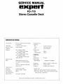
SERVICE MANUAL
GXpGrl
FD-710
Stereo Cassette Deck
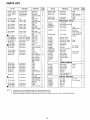
SPECIFICATIONS
recording
playback
Tape Speed
. 1-ll8 i.p.s. (4.75 cm/sec.)
Flutter
Wowand
0.07% (WRMS)
Frequency
Besponse
30-16,000H2 (t3dB)/
20-17,000H2(FeCrtape)
30-16,000H2(13d8)/
Track
System
Signal-to-Noise
Ratio
4-track 2-channel, stereo
lnput Sensitivity/
and
lmpedance
20-1 7,000H2 (CrOz tape)
30-14,000H2 (l3dB)/
20-15,000H2 (Normal tape)
(Dolby NR off)
53dB (Dolby NR off , CrO, or
FeCr tape, CCIR/ARM weighted
l
kHz)
The S/N is improved by 9dB
Dolby NR
on.
Total Harmonic
Distortion
Erase Ratio
..
lkHz,OdB)
65d8 (at 400H2, +10dB)
Bias Frequency . . . . 85kHz
Fast Forward and
Rewind Time . . . . . . T}seconds (C-60tape)
1.8o/o
(at
with
.
.
DlN..
MIC .
..
LINE
.
O.2bmyl12 kohms
lOmyl25 kohms
...2mvl10kohms
Output Level
LINE.
...350mV
HEADPHONES...750mV
GENERAL
Power
Consumption
40 watts
Power Supply
Power Supply
Dimensions
110/22OV AC,50/60H2
.
.
..
Weight (Net) . . . . .
Accessory
* DOLBY
442(Wl x 354(D) x 133(H) mm
7.2k9 (15.9 lbs.)
Shielded Audio Cables (2)
.
NR
o Dolby NR under license from Dolby Laboratories.
o The word "DOLBY" and Double-D-Symbol are trademarks of Dolby Laboratories.
Specifications and design are subject to change without notice.
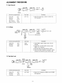
ALIGNMENT PROCEDURE
1) Head Azimuth
PLAY AMP.
DOLBY
AMP.
LINE
OUT
V.M
t
ADJUST
Controls to be positioned
Test Tape
Proced ure
Dolby
MTT.11 4
1) Adjust the head screw in order to obtain max.
V.M. indication.
OFF
120 s
NR
Equalizer
F
unction
P
Rec. Volume
Balance Volu me
2l
LAY
Max.
Center
VU Meter
DOLBY AMP.
LINE
METER AMP.
ADJUST
VU METER
IN
ADUST
APPLY 400H2
FO
R + 3d B
SV R4O1
SIGNAL
(sv R402)
LINE OUT
TP8O5
(TP806)
V.M
Controls to be positioned
Test Tape
NR
Equalizer
Function
Blank
Normal
Dolby
3)
: OFF
:120s
: R EC.
Proced ure
1) Apply 400H2,250mV signal at the LINE lN
terminal.
2l Adjust
R EC. and BALANCE volume to have
580mV V.M. indication.
3) Set blan k tape, then press the R EC. button.
4l Set the VU meter indication to DOLBY LEVEL
(double D mark position) witfr SVR 401 , 4O2.
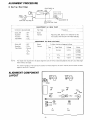
Play Back Level
AY
AMP.
SV R601
(sv R602) DOLBY
t
AMP.
METER AMP.
VU
METER
TP805
(TP806)
ADJUST
V.M 580mV
Controls to be positioned
Test Tape
NR
Equalizer
Function
MTT.1 50
Dolby
:OFF
Proced ure
1) Set the V.M. indication to 5B0mV with SVR601
:120s
602alignment.
: PLAY
-1-
ALIGNMENT PROCEDURE
4l Bias Trap I eias Voltage
R
EC. AMP.
TP603
(TP604)
SVR681
(sv R682)
V.M . (B)
(FOR
Br AS
\orrrsrMENT
VOLTAGE)
V.M. (A
(B)
)
(FOR BIAS TRAP)
I--
ADJUSTM EN T( A) ( BIAS TRAP}
I
I
controls to be
I
I
ootby
Test Tape
pos it io ned
p
I
I
-t
Proced ure
I
I
NR
: OFF
rq ua lizer
Function
:70s
: REC.
Tape Mode
: CrO2
tt_
Blank
Normal
t
i
Adjusting L631, 632 to min. indication on the
V.M. scale at the Test point of TP601 and 602.
I
_t
ADJUSTMENT (B) (BIAS VOLTAGE}
Dolby
NR
lizer
Tape Mode
Eq ua
: OFF
Adjust the bias voltages as follows.
Blank
Normal
:120s
: Normal
Tape Mode
Voltage
Normal
3.7mV
I
CrO2
Ad
just
SVR681
SVR 682
.1.
FeCr
t_
NOTE: Test tapes that required for the above alignment
CrO2
5.5mV
FeCr
4.ZmY
SV
R
683
are all TEAC brand and please do not carry out these align-
ment without test tapes.
All
al
uneven number
of Test points and Carbon trimmers aligns for the LEFT channel, and the other numbers
igns for the B I G HT channel
.
ALIGNMENT COMPONENT
LAYOUT
Sx,8I.
9e
U'E
u'Er
SV R682
'#o'
TP6O4
r
SVR631
TP6O2
@
t0
@
SVR602
SV R684
a
TP8O1
-2-
@
@
SV R683
!
TP8O2
t!
TP606
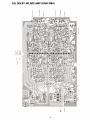
EQ: DOLBY NR,REC,AMP (DAM-I 66A)
====
66
--
oo
Jd
t_l
o
<
=
)
$k
st
*r
*H
-3-
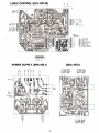
LOGIC CONTROL (DLC-I 38-1 B)
lil
SI@+'l
ssO+J
s6O+]
s7O+J
s8O-+
ssH
ntw
Pt,lJx6tR
tt
Ptux8tR
ItlT(lR
I0T0R, !ltIr,
tc
Ft llll ttO+{
PLIY tXD ttD <{t
ntw lll0 tt9<{lll
Rrc l;0 rro<-Onzl
rc-Jll7F
l--
O+ I lR R(lR AIP
o+ t,tcT swtlcH
O+ Gilo
o+ tRAsE PRoIEcI sf,tlcr
O+ rEroRY sutTcH
O)+ HAtt tc oul
o+ crsstlrt sf,rlcr 6r{0
L
=--_:_-._-"ra+,
ffiffilrrc(}+
'l
s
t
.856588666
tUllCTl0ll lry
(DDA-I 67A)
POWER SUPPLY (DPS-I 83-1 )
TO EQ:DOLBY
T0
NR. REC. AMP
( DAM -16 6)
(DAM - 166)
EQ: D9LBY
NR. REC. AMP
?0;il
snlcll
ilI]fr
r{jff6
TO
NR.
EQ:DOLBY
FI
EC. AMP
(DaM-166)
-4-
PARTS LIST
Part No.
INTEGRATED C!RCUIT
0'ty
Symbol No.
Description
&
COILS
2
1
1.8mH (MC129Yl
1 .2mH (RCA75)
Variable lnductor
lnductor
rc701
1
tc601,602
prPC4558
IC
IC
)
254963(O
)
R
Transistor
Transistor
Transistor
25C828(OR)
I
C80
1
,802
N
2
071 0
CONNECTORS
1
0731 ,733,735
0204, 401 , 402,
H LJ -O294-O1-O2
H LJ {.264-01-03
3
27
403,404,405,
cs728-1-2
406,407,408,
N41 572
MC03-021
409 , 410, 451 ,
601 , 602,603,
604, 651 ,652,
MC06-014
705,706,707,
713,721,722,
MC07-015
Transistor
Transistor
732,734,736
4202,704,709
0201 ,701 ,702,
Transistor
0708
1
N 13T1
P.U.T.
4711
1
88FM or 1 N60
or 20490
1S 1 555 or MA1 50
Germanium Diode
D401 ,402, 403
4
2SC 1 383(OR
25C2209 (OR
)
)
MC07-016
3
4
703
2SD592ANC(OR
)
MC09-017
MC09-018
DIODES
1
S1
404
Silicon Diode
D451,707,708
171825-3
171825-6
171825-7
171825-9
8
709,710,711,
W03B or 1N4002
S
ilicon
D
iode
721 ,722
D201 ,202,203
204, 209 ,21
1
15
,702,703,
704,705,706
58
Silicon Diode
Silicon Diode
D210,216, 217
D205 ,206, 207
HZg-2-B
HZ12-3-C
HZ24-3
G L-gP R2
Zener
Zener
Zener
Zener
LED
D iode
D iode
D iode
D iode
DZ2O3
DZ701
3
4
1
1
D.P.
D2202,702
1
1
Pote ntio meter
LED701 ,702,
5
Potentiometer
Carbon Trimmer
Carbon Trimmer
Carbon Trimmer
1
Carbon Trimmer
Carbon Trimmer
ESD-81541
U-520201-57
U-520202-57
F U-5231 52-57
F U-520501 -57
K L-258T-6
2
SVR684
1
svR401 , 402,
3
2
2
S1
1
s2,4
2
LSA-1 139
Slide Switch
Lever Switch
Lever Switch
Lever Switch
Lever Switch
Leaf Switch
80044-236334
BO1 41-26404A
P L1 2303003A
HKWo141-O1-010
Function Button
s11
sw4635021
ESL-2428
U
ESB7O97
s-N5053
S3
S5
1
Bias OSC. Unit
F
ilter, 1 9k Hz
1{
7 -Ptn
7-P in
9-Pin
,l
9-Pin
1
1
2
1
1
Audio Cable
2
Line Cord
1
Amplif ier P.C.B.
Logic Control P.C.B.
Logic Switch P.C.B.
Power Supply P.C.B.
1
1
1
1
So len
oid
SL3
&
1
LAMPS
Fuse (200mA)
F use l2Al
Fuse (3.1 5A)
Fuse (500mA)
Level Meter (Silver)
Lamp
Lamp, Meter
Lamp
,2
2
FU6,7
FU8,9
LA903,904
LA903, 904
2
2
2
2
2
LA9O5
1
FU1
FU5
1
LA901
,902
Fuse Holder
Metal Film Resistor
R81
R702,703
2
2
2OpF
Ceramic Capacitor
c607, 608,659
4
1
,812
CAPACITORS
1
660
s13
200pF
1
Ceram ic Capacitor
c647, 648,681
4
ffi2
osB681
1
27OpF
MCO.01pF
Ceram ic Capacitor
c825,826
2
Ceramic Capacitor
c713,714,715
4
SCO.05pF
Ceram ic Capacitor
716
Ft L801
,802
c201
204
2
-5-
l
14
Wire-Wou nd Resistor
1
FILTER
12A-1120
rl
6-Pin
%w 3.3K0
7W 39r}
2
BIAS OSC. UNIT
53T-003 or 191004
1l
3-Pin
Micro Plug,3-Pin
Micro Plug, $-Pin
M icro Pl ug , 7 -Pin
Micro Plug,9-Pin
Strain Relief , Line
nit Ass'y
AC ON/OFF Switch
I
RESISTORS
1
s6, 7
s12
Headphone Jack
Mic Jack
8 Hole D lN Socket
4-Pin Jack
Micro Connector
Ass'y
Micro Connector
Ass'y
Micro Connector
Ass'y
Micro Connector
Ass'y
Micro Connector
Ass'y
Micro Connector
Ass'y
FUSE HOLDERS
SW!TCHES
sw4435013
80005
F
1
svR631 ,632
svR681 . 682
sw4235012
40
F
1
svR601,602
1633. 634
TERMINALS
FUSES, METERS
683
10K (B)
100K (B)
S-1
.704,705
V R6O1
V R6O2
,632
L631
2
2
2
SOLENO!D
CONTROLS
EWK-HW A332A24
EWK-G4 A323703
EVT R4AOOB24
2K (B) , g0
5K (B)
O
D.A. M-1 39
D. L. C-1 38
D. L. S-1 38-1
DZ2O1
703
&
1
T401 ,402
PRINTED CIRCUIT BOARD
208
HZ6-3-A
a set
Cord
PC-002
ACC.Ol
701
1N4002
R3P.4
,
212,213,214,
GP.1
S
O'ty
TRANSFORMERS
Power Transformer
Output Transformer
IC
c603
&
PTO435S
1 62005
LSI
r
Symbol No.
Description
T RANS!STORS
TCg121P
T A7 122AP
or TA7122BP
N E6468N
2SAs64(OR
Part No.
a set
,202,203
4
I
PARTS LIST
Part No.
Symbol No.
O'ty
Polypropy lene
Polypropy lene
c815,816
Po ly pro py le ne
c8
560pF
Polystyrene
c603, 604,645
oir
Mylar lt5o/ol
Mylar ftS%l
646
c251 ,252
c645, 646
c61 5, 61 6, 649
650, 656
2
2
5
(t5o/ol
c662
1
lt5o/ol
c655, 661
c65 1 , 652
1
O3M
50V 0.0012pF
50V 0.0068pF
2
2
2
c817, 818
1
9
,820
2
2
N30252-2
sOV 0.056pF
sOV 0.1pF
My lar lt5o/ol
My lar (t1o/ol
c657,658
c633, 634, 805
2
ECEAsOM
lEc
R33
ECEASOM R47 R
lec
ECEAl6M 1OR
lrc
I lroOTW 47 pF
I 1OTW
ro
100pF
,Offi 22OpF
',gB
1OTW 47OpF
1OTW 33pF
l;.
I ro
1OTW 1000pF
1OTW 22OOqF
ro
16TW
4.7 pF
ro6TW 1 OpF
1
N
lectrolytic (0.33M )
Electrolytic (0.47M)
Electrolytic (10M)
E
lectrolytic
Electrolytic
Electrolytic
E lectrolytic
E Iectrolytic
E
lectrolytic
Electrolytic
E lectrolytic
E lectrolytic
E
c81 1 ,812
c601 ,602
c21 6
1
N41 265
c637,638
c215
c61 1 ,612,217
2
N302544
c407, 408 ,643
644
4
1
1
1
1
1
I
lectrolytic
Electrolytic
E lectrolytic
Electrolytic
E lectrolytic
Electrolytic
E
E
lectrolytic
Electrolytic
22OpF
II 25TW
gslru 22opF
E
lectrolytic
.lrlSrw 10OpF
lectrolytic
Electrolytic
E lectrolytic
1
c206
1
nob Guide
1
1
1
Timer,
Memory Switch
Bias, EO,
lnput Switch
Knob Guide
Side Cap, Right
Side Cap, Left
Push Button, Power
Push Button, Eject
N41 233
N41281-S
Knob, Lever
Reset Button
Knob 21
Knob 44
N41 291
N41 661
N41 660
Power ON/OFF
Switch
4
1
1
1
Power
Eject
1
1
6
1
Rec. Balance
Rec. Level
1
1
Meter Window
Cass'Window
Counter Window
tJ203g8
T.C
Case
1
Foot
4
1
N41 31 0
N41 261
c21 4
1
N41262
Switch Shaft
Shaft Coupler
Shaft Coupler
c707
1
N41
2
N41 294
4
N41 295
c219
1
c667,668
c212,403,404
631 ,710,807,
813,814,821,
2
16
N
30251 -B K
c704
c705
c802
c663 ,664
c401 ,402,641
c210 , 617,
c209 ,21
61 8
1
c250
c731
2834
N41 258
c213, 609, 61 0
639,640
c208,605,606
5
.732.733
oM-1 52
N41 31 8
H
1
1
1
1
1
Power
1
Front
1
Rear
1
Eject Spring
Spring A
Spring B
1
1
1
Cass'Holding Spring
lnstruction Book
Poly.Bag
Poly. Bag
5
N40487
N20389
2
N203904
Pad, R ight
Pad, Left
N41 424
N41 662
Pad, Top
Carbon
3
1
older
Logic Cont.
Cass'
1
1
PACKING MATER AL
6
1
1
MISCE LLANEOUS
1
1
r
For Unit
For lnst. Book
NOTE: 1. Part orders must contain Model Number, Part Number and Description.
2. Ordering quantity of screws and/or resistors must be multiple of 10 pcs.
3.
1
N41 443
N41 250-T
N41 109
1
683,801
I
c708
N41266-8K
N41 293
c218
635, 636,669
E
6
Cass' Compartment
Meter Plate
Top Cover
Alum. Plate
642
25TW 100pF
I
lytic
BK
N41 232
666
lectro
K
N30248-8 K
808 , 632,665,
E
1
c405, 406, 684,
Dolby N R Switc
2
2
2
2
823,824,822,
1,.
16TW 47 pF
I ro6TW 00pF
I ro6TW 22OpF
ro
1000pF
I 16TW
lzs
25TW 3.3pF
lzs
25TW 1pF
lzs
25TW 4.7 pF
l,u
25TW OpF
$ut* 47rff
Cass'Holder
Knob Guide
30252-1
N30209-1
3
1
c7 21
Pane!
4
806
a sst
APPEARANCE PARTS
Front
4
c452, 709
c803, 804
!ectrolytic
Electrolytic
E
Cass' Window Mtg. B
c653 ,654, 809
810
c205
O'ty
706,711,712
50TW 2.2pF
50TW 22OpF
N41095
N20395-8 K
G5o/ol
Mylar lt2Oo/ol
50TW 0.1pF
50TW 1pF
Electrolytic
Electrolytic
Electrolytic
N 101 14
Mylar
My lar
Mylar
Mylar
\ho
Uov o.o33pF
35TW 1 OO0pF
Symbol No.
Description
4
50V 0.0082pF
50V 0.01pF
50V 0.01 2pF
50V O.O47 pF
(t1o/ol
Part No.
a set
ECO-P 1472F2
ECO-P 1562F2
ECO-P 1273F2
ECNC4A
I
I
Description
Resistorsnotdetailedinpartslistareall carbontype%watt,withregardtothevalue,refertotheschematicdiagram.
-6-
1
1
1
1
1
1
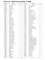
PARTS
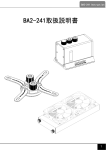
LIST CASSETTE DECK MODEL
Parts No.
Description
O'ty
CT.33O9B
Parts No.
FF !dler Arm Collar
Arm Collar
A0170
Drive Arm Ass'y
1
A0180
A0190
A02000
A0230
Reel Ass'y SA
1
v3210
v3960
Case Lock
Reel Ass'y TA
1
v 4470
Motor
Drive Pulley Ass'y
1
Lug
Soft Dumper Ass'y
1
c0390
Counter
1
S, K Binder
1
E1310
Hall Generator
1
x1920
x4110
x4580
x4910
x4970
E1
360
O'ty
Description
Pu
1
1
lley
1
3
E
Washer
1
Pressing Metal
1
Action Arm Bracket A
Action Arm A
1
1
F01 30
Fly wheel M
1
x4980
Head Panel Pushing Plate G
1
G0430
E
rase Head
1
x 5040
Rew. Arm
1
G1340
R/P Head
1
Head Panel Pushing Plate J
G1350
Motol:
1
x6330
x6340
J01 00
Pinch Roller
1
x6350
J0280
Rew. ldler A
1
JO440
Pinch Roller Arm
1
J0460
Shaft Supporter
1
J0640
Cass' Guide LA
1
J0650
Cass'Guide RA
1
J0670
Pu
K1640
lley (For String)
FF ldler Arm Ass'y
FF Action Arm Ass'y
K1660
Action Plate Ass'y
1
K2090
Chassis Ass'y
1
K21 00
Head Panel Ass'y
1
K2360
Sub Chassis
1
x6370
x6380
x6390
x6400
x6410
x6460
x6570
x7140
x7160
x7180
x7210
x7220
K1630
K2440
P01
30
F
G
B
F Lever Ass'y A
Solenoid Ass'y
o0240
01990
02010
02020
o2050
o2060
o2080
o2100
R/P Head Spring B
Pinch Roller Spring
FF Action Arm Spring
021 10
Action Lever Spring
Action Lever Spring
Action Plate Spring
42140
o2150
02260
1
Solenoid Arm RB
1
Solenoid Arm LB
1
Motor Holder
1
R
lC Board Bracket A
1
Rew Lever
1
Lock Bracket
B
Back Tension Brake
1
C
1
Drive Arm Pushing Plate A
1
1
01 105
Supporting Plate For Brake A
Screw 2.3x4
2
01 111
Screw 2.3x1O
1
01144
Screw 2.6x3
6
1
01151
Screw 2.6x10
2
2
2
2
2
01 166
Screw 3x5
04085
Screw 2x4
1
Brake Arm Spring RA
1
17165
Screw 3x5
1
1
Brake Arm Spring LA
1
1
8086
Bind Screw 2x5
Action Plate Spring
1
1
8088
Bind Screw 2x7
Drive Arm Spring
1
19145
Screw W/Spring Washer
1
191 46
Screw W/Spring Washer 2.6x5
14
1
191 49
Screw W/Spring Washer 2.6x8
2
1
191 55
Screw W/Spring Washer 2.6x14
1
1
19166
Screw W/Spring Washer 3x5
4
Erase Head Spring
Micro Switch SS-SG L13
String Ass'y
Rec. Sensor Ass'y A
Counter Belt
u0340
u0600
u0840
u0850
u0860
u0890
u1080
u1300
u1310
1
Solenoid Arm Guide A
1
1
Back Tension Spring
u01 70
1
Head Panel Pushing Plate K
1
s0340
T0220
1
2
1
Rew. Arm Spring A
0231 0
T021 0
1
1
Flywheel Supporter O
M icro Switch Bracket
Cass'Hold Back Spring Plate
R
ubber Cush ion
justing Screw
'
1
2.6x4
1
1
201 48
Screw W/Flat Washer 2.6x7
3
1
21
046
Screw W/Flat Washer 2.6x4.5
2
1
21
050
Screw WlFlat Washer 2.6x6.5
1
2
23007
Tapping Screw 2.6xG
3
1
2301 4
Tapping Screw 2.6x5
5
3
27026
Spring Washer M2.6
2
lat Washer 2.8x7.5x0.5
1
301 26
F
Brake L
1
32201
P.S.W 2.1x4xO.13
1
Brake
1
32252
P.S.W 2.6x4.7x0.25
4
Ad
R
2
Rubber (For Brake)
2
33077
Spring Pin 3x 1 6
2
Reel Cap C
2
351 04
Drive Belt
1
3601 5
2
2
36020
ivet 2x3
E Rins E-1 .5
E Ring E -2.O
1
36025
E Ring
-2.5
2
1
42025
steel Ball M2.5
R
ubber
C ush
ion
u1500
Main Belt
Felt 1 x6x4
v2910
Collar 2.8x3.5x5
C
1
-7-
R
E
2
6
6
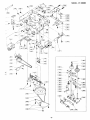
EXPLODED DIAGRAM
[l.tlY'-'-i_rysio
fo_rra
-J--
- _-4
_
f-
I r!r'- Y/'
I rsros
Y.'
-/
I
(
i,
9
) rr+-!!+Lt
NH
:<
iD
i-lr:
)'> .)rb{xrszol
-{orru
.?.
-.-%---[srcs
-f
IJol,-{U
.{
l-L- o:' -A6
o.2"o
:*rM
-il=-..
\>,
\L
I
xrs2o
]
-8-
J
]
MODEL CT-33098
,4
K
_j-
-/ ,z'
LEq!
|
g___{_r-E
&---@rl
{-rre
----,g
----@l
tC
---@E
-{rrd
I
6-
\
tE4-.f xzzo|
aoJ
.-.1
@l==_-
I ozrcol
' \')
teerq}-
tot%,
o
I
o
,se
-9-
L,qlql
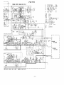
CIRCUIT DIAGRAM
TlIGIG
r
BllARII
GOXTRllT
mtG -t38Bl
tIl0It
I
0
o
I
l.0s
rB-t r
!0r10
I
==
o=
o
o
-9t
3Ei
l,l,
!s;
lrI
60
0 0|
(0ts ll!)
illtn
rl3
=r'9
Cr13
rc s;tICl
rc I0r
s6?
.
t uxcl
Ssl
l0r
ttY
coxIr0[
i'"
t0clc
loo
lr
r
ffi=g,.ot'\,0,
!*:tj
rc
I
rrorrl
L:l:=
I
rtrott
tI tcI
0
lrr
I
st
Yr*
oc rolor
lo,*
r 0I?02
-------r\
o
IUIll
0t /0i1
r-- -
E+
o:
croc-
!
0.033
!
I ful'l'
Jrrrr
1_
IUI(I
!=l
ril
I
I
R6r3
r
c563:
SSI
lrurz
P505
c605
R6r5
=
^^!-U rrPur E
R60'
330r
f
t2t.56t
lcE0l
o
o
c6
R663
tltl
*
r6t
-
G
t05
l-"Tl
sr9
rt?
slll
RlP
00061
20[ '- s3 |
to
st13
xtp
s5
xl
@'-
l:f
It'
r.
c.-
t-l
o
5
00t 0Y
l/P
3
00t BY xR
=i
o
o
o>
tr l
Slll :+
,#l
---ll,-
tl
vv
5)
(5
ro
t33
(J
I
3
o
I rir
IPS(l{
I
R60{
Y
(J 6)
to. llo[By xt. ntc
rrp
?tv
+l3Y
t,P s;ttcttD
P C.80lR0
,,i ,,7 [l[, iil lis3 3, ,l^
ll?
X/?
Jr
J t0
s,
6
1l?
___
- 10-
sl ,
s56
ll(lTBY
s5
I
r; "u
IT
t"
00trYrr__
_
'''_
E0rlUz
FO'71O
?orEn suPPtY B0AID
!.tiA
R/6.
(lIPs - t83 I
--x
tt
ttc/ lttt srrrctt
IIPUI STTTCI SIIICH
t0 stttcr srtlcr
BrAS StttcI sflIcH
00tlr tt I IPI frt s:lIcH
nrtn sfrrcH ttc,/tttt
rtr0rY turclr0r srrlcll
rtr0lY 0tttcI sIlIcll
ttlsurt Pt0rtcI srtIcI
rulorlnc ot/ott srr IGtt
trlr{ clsstllt
furclr0t rtY sfllcll
trtcr srrIcI
P0itn sttIcH
sr
s?
s3
I
lr
Pr r#15 s
001
r --r
st
s5
s6
s,
st
s9
il
sr0
s
Lt'rj
ll
s 12
s 13
uPil55!C
IA
'I?2?
rt5{5
I
C
03
0r
50?
91 2 t P
0rt!r
2Srllt
?srr6r
t0t. (02.,?1,65r.652,
2SCt2l
493, a69. r?2.
?sc t3t3
?sc ?209
I l3I r
,32.'r3
0
,0r.
0
t02, ,03
,0
-,
,
,35
'tr.
0
rsrtttl
9?n2 tto
Il r50( tst555) I
0
,0t. ,02.
cr
t0
F--*oi
i'i-oii-lvfi
---?
s5 r
s5
--1
3B
I
I
lt0e2)
,03. r01
0
.
trt002
0
?t0
o
-J
6
o
o
6PI5B
?0 l.103. 20 r, 20t
Ilt50
I 21.t22,
.12 5
o
r;;:]
L- -J
| ,,,0
stlSll
(l)
@
c635 E
l00l
17p
Sl
15
V? S;lICilt0 +2 3 t
?5Ya,
J,,.
R633
I
5
33[
|
25lal R65
rrx
cSa l
oci
o
t t l0lr{
R553 c0l3
c03t
-€
i;--
o*
@o
8= _]Oo
,1oo'q,o,
Er-
!'/f
orol
I
o{oe
E,6
I
lom
t
;t=
3Ie-rA
=6
lct
I
olt
tr,rP
, c. B0AR0
!
I
g
E
t,
I
I
I
',31
I
( RtrtR r0
tttI
YU ITITR
st0r
)
I
I
I
o
E
csrs E
-ul
?5V.
3E I rror
E- I cots
'
I
t63?
lta[
R63a
I
33[
€F'
c5r2
(Jo
Rsil
c53?
2lr
e
C6a1
Rt
0601
---? r,a
E
:lt
e
E
rl
2.11
-
o
o
J
o
o
@
-9
-o
,@
o
e
o
sr
5
"t---------'o
D0t8r,
lllUztB,
-
tEc ltt
ttrtD
--------J
fltA]tt- t66t
-1 1-
Push Button
Power
Case
N20398
N41 281 -S
Cassette W indow
Meter Plate
Front Panel
N41250-T
N30251-BK1
N 101 14
QiQ
Knob Guide
N30209-1BK
Push Button
Ej
@
ect
N41 265
r-r@
Headphone Jack
H LJ-0294 01-O2
K
nob 44
N41 660
Knob
EEE EEE
Knob Guide
N30252-2
F
Reset Button
Cassette W indow
oot
N41291
Mtg.Bkt.
T.C
K nob Lever
N302544
H
Knob Guide
N
MIC Jack
N41 095
21
N41 661
30252-
1
LJO264-01-03
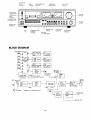
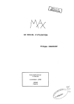
BLOCK DIAGRAM
F
KEY
UNCTION
REW
rc701
0701 ,702,731
F.F DR IVE
SOLENOID
AMP.
-
F.F
o
F U
NCTION
L21
KEY
PLAY
oo
CONTROL
oo
R
SLl
,
732F.F DRIVE
2
oc
LOGIC
EC.
o703
STOP
o
SL3
REC. SOLENOI
REC. DRIVE
DRIVE AMP.
SOLENOID
PAUSE
OC
0704
MOTOR
DR IVE
I
0705, 706
707,711
REC.
F.G SE RVO
DC MOTOR
FULL AUTO
i sxur.or
r
ctRcutr
TO RIP
HEAD
LEVE L
METE R
{+PLAY
,,,J
-
r
c601
0407
0601, 603
EOUALIZER
R
AMP.
M1
MUTI NG
EC. AMP
CIRCUIT
V R6O1
RlP H EAD
SHOWN LEFT CHANNEL ONLY
0409
MUTI NG
H EADPHON
JACK
CIRCUIT
LINE OUT
-12-