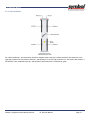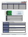
1
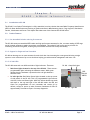
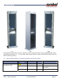
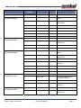
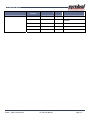
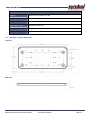
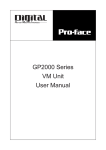
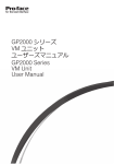
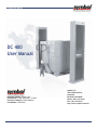
DC 400 User Manual DC 400 User Manual Symbol, Inc. 7361 Calhoun Place, Suite 250 Rockville, MD 20855 Phone: (301) 610-6100 Fax: (301) 610-6101 http://www.symbol.com/rfid Document Version: Version 1.02 Release Date: Friday, December 17, 2004 Document Category: Product Manuals Part Number: 110012-001 DC 400 User Manual DC 400 User Manual Notices Copyright © 2005 Symbol, Inc. All rights reserved. This document is protected by copyright with all rights reserved. No part of the document may be reproduced or transmitted by any means or in any form without prior consent in writing from Symbol, Inc. Trademarks Symbol is a registered trademark of Symbol, Inc. All other product names or logos mentioned herein are used for identification purposes only, and are the trademarks of their respective owners. Statement of Rights Symbol products incorporate technology that is protected by U.S. patent and other intellectual property (IP) rights owned by Symbol, Inc, and other rights owners. Use of these products constitutes your legal agreement to honor Symbol’ IP rights as protected by applicable laws. Reverse engineering, de-compiling, or disassembly of Symbol products is strictly prohibited. Violators will be prosecuted. Disclaimer While Symbol has committed its best efforts to providing accurate information in this document, we assume no responsibility for any inaccuracies that may be contained herein, and we reserve the right to make changes to this document without notice. The DC-400 weighs 150 lbs (68.2 Kg) and has a robust design. However, proper equipment should be used to transport the DC-400 from one place to another. Please ensure that the DC-400 is securely mounted to the floor / ground. Symbol assumes no responsibility for any damage resulting from incorrect transportation / mounting. DC 400 User Manual DC 400 User Manual Table of Contents Chapter 1. Introduction .................................................................................................................. 1 1.1. Scope............................................................................................................................... 1 1.1.1. Target Audience ............................................................................................................... 1 1.1.2. Assumptions.................................................................................................................... 1 1.2. Document Organization ......................................................................................................... 1 1.3. Document Conventions.......................................................................................................... 2 1.4. Abbreviations ..................................................................................................................... 2 1.5. Additional Documentation Available.......................................................................................... 2 Chapter 2. DC400 – A Brief Introduction .............................................................................................. 4 2.1. Introduction to DC 400 .......................................................................................................... 4 2.2. Product Features................................................................................................................. 4 2.2.1. Pre-Assembled Solution reducing Procurement.......................................................................... 4 2.2.2. Support for Single and Dual Coverable .................................................................................... 4 2.2.3. DC 400 LEDs .................................................................................................................... 4 2.2.4. Motion Detector (Optional Component)................................................................................... 5 2.2.5. Robust........................................................................................................................... 5 2.3. The DC 400 Configurations ..................................................................................................... 5 Standard Edition....................................................................................................................... 6 2.3.1. Professional Edition .......................................................................................................... 7 2.4. DC 400 Models .................................................................................................................... 7 2.4.1. 2L Models ....................................................................................................................... 7 2.4.2. 2R Models....................................................................................................................... 7 2.4.3. 4 (Dual) Models ................................................................................................................ 7 2.5. What’s shipped (Summary of components shipped with different models) ............................................ 8 Chapter 3. DC 400 Installation .........................................................................................................11 3.1. Possible Arrangements ......................................................................................................... 11 3.2. Installing Power cables and Ethernet cables ............................................................................... 12 3.3. Mounting the DC-400 to the Floor ............................................................................................ 13 Chapter 4. DC 400 LIB and Motion Sensor Wiring .................................................................................14 4.1. LIB Power Wiring ................................................................................................................ 14 4.2. LIB to DC 400 Connections..................................................................................................... 15 4.3. Standard DC 400 Red and Green LEDs to LIB Connection Information.................................................. 15 Table of Contents DC 400 User Manual Page i DC 400 User Manual 4.4. Motion Detector to the DC 400 Connection Information.................................................................. 15 4.5. Further configurations for Motion Sensor ................................................................................... 17 4.6. Motion Sensor Jumper Settings ............................................................................................... 17 Chapter 5. Setup & Configuration With Motion Detector.........................................................................18 5.1. Basic Antenna Setup and Configuration for Polling with Motion Detector ............................................. 18 5.1.1. Single Sided Shelf With Two Antennas ................................................................................... 19 5.1.2. Dual Shelf ..................................................................................................................... 19 5.2. Light Indicator Bar Configuration ............................................................................................ 20 5.2.1. Single sided installation .................................................................................................... 20 5.2.2. Dual installation.............................................................................................................. 21 Appendix A. Mechanical and Electrical Specifications ............................................................................23 A.1. Mechanical Specifications ..................................................................................................... 23 A.2. Electrical ......................................................................................................................... 23 A.3. GPIO Signals For DC 400 Light Indicator Box (LIB) ......................................................................... 23 A.4. Motion Sensor (Pin outs) ....................................................................................................... 24 A.5. Other Technical Specifications for Motion Detector ...................................................................... 24 A.6. Base Plate – Physical Dimensions ............................................................................................. 25 Appendix B. Additional Software Commands .......................................................................................26 B.1. XML Commands for Controlling LEDs......................................................................................... 26 Table of Contents DC 400 User Manual Page ii DC 400 User Manual C h a p t e r 1 . I N T R O D U C T I O N 1.1. Scope The Symbol DC 400 User Manual provides the following information pertaining to Symbol DC 400 Portal solution: Features and Description Hardware Specifications and Hardware installation details. 1.1.1. Target Audience This document is intended for: Field Support teams performing installation of DC 400, and For end customers for use as a brief product description. Description for the RFID reader is detailed in the AR 400 User Manual and description of the utility is detailed in the TagVis product manual (see references below). 1.1.2. Assumptions This manual assumes that the reader understands the basic working concepts of RFID, working knowledge of Symbol AR 400 reader and the following: Basic networking terms e.g. IP Address, DHCP, Protocol etc. Basic RFID terms e.g. Reader, Tag, Antennas, Read Point etc. The manual is not intended to provide detailed information on the above-mentioned topics. 1.2. Document Organization This document has been organized as described in the table below: Chapter No. Chapter Title Information Contained in the Chapter 1 Introduction An overview of what the Document contains, who the targeted audience is and how the document is organized. 2 DC 400 – A brief introduction An introduction to DC 400, its components and configurations and overview of its features. 3 DC 400 - Installation Step by Step procedures to help you setup the Hardware. 4 DC 400 LIB and Motion Sensor Wiring Describes how to connect various DC 400 components to the Light Indicator Box (LIB) 5 Setup & Configuration With Motion Detector Provides guidelines and necessary information that is required for working with DC 400 with a motion detector Hardware Specification A brief description of DC 400 hardware and tabular representation of product specifications. Appendix – A Introduction DC 400 User Manual Page 1 DC 400 User Manual Chapter No. Chapter Title Information Contained in the Chapter Appendix B Software Specification A Brief tabular specification of software commands which DC 400 accepts. 1.3. Document Conventions The following Conventions have been used in this User Manual: Document Convection Bulleted List 1. Numbered List Version Provides Grouped Action and non procedural steps Procedural steps for performing an action. A Note / Focus point that the reader might be interested in knowing. A Warning Note. A Caution Note. Note: The use of colors in this document conveys information which may not be easily conveyed to readers who are using a grayscale version of the manual. Symbol recommends using colored Monitors / Printouts while reading this manual. 1.4. Abbreviations The Following acronyms and abbreviations have been used in the Manual: Acronym / Abbreviation Expansion / Explanation RFID Radio Frequency Identification EPC Electronic Product Code - industry-driven standard of identification scheme for RFID Tags. Read Point An individually addressable antenna Read Point Class Configuration Parameters that may be applied to one or more read points 1.5. Additional Documentation Available The following additional documentation may be useful to the users of this manual: AR 400 User Manual (PN: 110003-001) API Programmer’s Manual (PN: 110009-001). Symbol TagVis User Manual. (P/N: 110004-001) Introduction DC 400 User Manual Page: 2 DC 400 User Manual AR 400 Release Notes http://www.matrics.com (for FAQ and Product Updates) http://www.symbol.com/rfid (for FAQ and Product Updates) Introduction DC 400 User Manual Page: 3 DC 400 User Manual D C 4 0 0 C h a p t e r – A B R I E F 2 . I N T R O D U C T I O N 2.1. Introduction to DC 400 The DC 400, from Symbol Technologies is a fully assembled, turn-key solution that uses Radio Frequency Identification (RFID) for Asset identification and tracking of goods movement in Manufacturing plants, Cargo Logistics, Distribution Centers, Warehouses and Stores. This chapter describes some of the features that DC 400 offers. 2.2. Product Features 2.2.1. Pre-Assembled Solution reducing Procurement The DC-400 comes pre-assembled RFID reader and high performance antennas for fast, accurate reading of RFID tags and all internal antenna-to-reader connections pre assembled. This makes DC-400 a true turn key solution for monitoring dock doors using RFID, reducing the procurement time and cost setup considerably. 2.2.2. Support for Single and Dual Coverable DC 400 can leverage two or more antennas for each dock door thus increasing the coverage and allowing a single system to cover a distance of up to two dock door helping you achieve easier management and lower cost. 2.2.3. DC 400 LEDs The DC-400 comes with two different kinds of light indicators. These are: DC 400 – Green Red Lights Red-Green Lights situated on the top of the DC-400 – These are nonprogrammable lights indicating the hardware status. While green denotes that the hardware is powered on the red light denotes a hardware fault. DC 400 Light Bar: Red-Yellow-Green Lights situated on the top corner of side pannel of the DC 400. This is a programmable light indicator with Red, Yellow and Green lights. While the Yellow denotes tag reads and maps to the tag read light of the AR 400 reader the Red and Green are programmable via xml commands and remain off by default, except for power up when firmware illuminates all LEDs for approximately 5 seconds as a part of startup diagnostics. DC400 – A Brief Introduction DC 400 User Manual RED YELLOW GREEN DC 400 – Light Bar Page: 4 DC 400 User Manual 2.2.4. Motion Detector (Optional Component) The Professional version of DC-400 comes with a motion detector which is capable of initiating reads when movement is detected. This ensures that the antennas are reading tags only when tag movement occurs through the dock door i.e. when pallets are passed through the DC400 system. 2.2.5. Robust The DC 400 is built to sustain minor non-direct pallet impact. It provides a bolted installation making it robust enough to be used in an industrial environment. It is designed to meet IP54 specifications for dust and water resistance and ensures better uptime in harsh industrial environments. The DC 400 can work in temperatures varying from -20O C to 70O C and humidity of 5% to 95% RH Non Condensing. 2.3. The DC 400 Configurations The DC 400 comes in multiple configurations. A Left, right and dual DC 400 configuration is available for monitoring different types of dock doors. Also available are the Professional and Standard versions that give better cost options and components to businesses depending on their exact requirement. This section describes the various models available and how these models can be used individually and collectively to meet your business requirements. The DC 400 comes in two editions. These are: Standard Edition Professional Edition. The subsections that follow describe these editions in detail. DC400 – A Brief Introduction DC 400 User Manual Page: 5 DC 400 User Manual Standard Edition The standard edition of DC 400 offers models to choose from. These models with their functionality have been described in detail in the following section. However, all models of the Standard edition usually come with the following components: DC 400 Dock Door Frame Æ The Dock door frame provides a bolted installation and is used to house the AR 400 reader and high performance antenenas. 1 AR 400 RFID Reader Æ Symbol RFID Advanced Reader. For more information on AR 400 please reffer to the AR 400 User Manual. High Performance Antennas Æ that can be connected to the AR 400 allowing users to read tags in the Read range. For Dual models the DC 400 ships with 4 high performance antennas and for left and right models DC 400 ships with 2 High performance antennas. DC400 – A Brief Introduction DC 400 User Manual DC 400 Frame AR 400 Readers High-Performance Antennas Page: 6 DC 400 User Manual 2.3.1. Professional Edition The professional editions of DC 400 come with all components that are offered in the standard editions plus the following additional components: Light Indicator Bar Æ The professional edition of DC400 comes with two different types of light indicators. The first indicator is located at the top of the reader and consists of non-programmable green and red light. While a green light denotes that the device has been powered on, a red light denotes a hardware fault. The second light indicator is located at the top of the side panel and contains green, red and amber lights. While the amber light denotes tag reads the red and green are customer configurable and programmable via xml commands and remain off by default, except for power up when the firmware illuminates all the lights for 5 seconds as a part of AR 400’s diagnostic. Motion Sensor LIB Antennas AR 400 Reader Motion Sensor Æ Activates tag reads when pallets are detected in motion. 2.4. DC 400 Models All DC 400 Editions that have been described above offer 3 different models. These are as follows: 2.4.1. 2L Models The DC 400 2L models come with two high performance antennas mounted on a single compact frame that can be placed on the left side of the Dock door. It comes in both standard and professional editions but is primarily mounted as a paired system with either a DC400-4 (Dual) Model or a DC400-2R (Right) Model. 2.4.2. 2R Models The DC 400 2R models come with two high performance antennas mounted on a single compact frame that can be placed on the right side of the Dock door. It comes in both standard and professional editions but is mainly used to be mounted as a paired system with either a DC400-4 (Dual) Model or a DC400-2L (Left) Model. 2.4.3. 4 (Dual) Models The DC400-4 (Dual) model comes with 4 high performance antennas mounted on a single compact frame that can be placed on the middle of two Dock door. It comes in both standard and professional editions but is primarily mounted as a paired system with either a DC400-2R (Right) Model or a DC400-2L (Left) Model or both. DC400 – A Brief Introduction DC 400 User Manual Page: 7 DC 400 User Manual Left Dual Right The professional Dual models come with “1 Red and 1 Green” status light indicator and 2 Programmable Red, Amber and Green light indicators (i.e. – 1 on each side). Having a light indicator on each side helps identify which side of the dual DC 400 a tag is passing. 2.5. What’s shipped (Summary of components shipped with different models) Model Name and Number DC 400 Dual Standard (DC-400-4-US-STD) DC400 – A Brief Introduction Symbol Part Number [TBD] Old Part Number Quantity Description 250032-001 1 DC 400 Standard Dual Model. 201538-001 1 DC Dock Door Frame Assembly (Dual Model) 201510-001 1 AR 400 Reader DC 400 User Manual Page: 8 DC 400 User Manual Model Name and Number Symbol Part Number Old Part Number Quantity Description 210523-001 1 High Performance Antennas 250033-001 1 DC 400 Professional Dual Model. 201538-001 1 DC Dock Door Frame Assembly (Dual Model) 201510-001 1 AR 400 Reader 201523-001 4 High Performance Antennas 250100-001 1 I/O Box Kit 250101-001 2 Light Bar Kits 250102-001 2 Motion Sensor Kits 250034-001 1 DC 400 Standard Right Model 201538-003 1 DC-400 DOCK FRAME RIGHT SINGLE ASSY 201510-001 1 AR 400 Reader 210523-001 2 Area Antennas 250035-001 1 DC 400 Professional Right Model. 201538-003 1 DC-400 DOCK FRAME RIGHT SINGLE ASSY 201510-001 1 AR-400 Reader 201523-001 2 High-Performance Area Antennas 250100-001 1 I/O Box Kit 250101-001 1 Light Bar Kit 250102-001 1 Motion Sensor Kit DC 400 Standard Left 250036-001 1 DC 400 Standard Left Model (DC-400-2L-US-STD) 201538-002 1 DC-400 Dock Door Frame – Left Single Assembly 201510-001 1 AR-400 Reader 210523-001 2 High-Performance Area Antennas 250037-001 1 DC 400 Professional Left Model 201538-002 1 DC-400 DOCK FRAME LEFT SINGLE ASSY DC 400 Dual Professional (DC-400-4-US-PRO) DC 400 Standard Right Model (DC-400-2R-US-STD) DC 400 Professional Right (DC-400-2R-US-PRO) DC 400 Professional Left (DC-400-2L-US-PRO) DC400 – A Brief Introduction DC 400 User Manual Page: 9 DC 400 User Manual Model Name and Number DC400 – A Brief Introduction Symbol Part Number Old Part Number Quantity Description 201510-001 1 AR-400 Reader 201523-001 2 High-Performance Area Antennas 250100-001 1 I/O Box Kit 250101-001 1 Light Bar Kit 250102-001 1 Motion Sensor Kit DC 400 User Manual Page: 10 DC 400 User Manual D C C h a p t e r 3 . 4 0 0 I N S T A L L A T I O N DC 400 is a true turn-key solution and provides an easy bolt and use solution. This chapter describes how the hardware and various components can be installed making the DC 400 ready to use. 3.1. Possible Arrangements The different DC 400 models can be arranged in different configurations as per the user requirements to help lower cost and increase ROI, thus providing the maximum benefit to the user. This section describes how different models of DC 400 can be used together to provide better performance and lower cost. 1 Left 1 Right Æ if your requirement consists of a single dock door you might consider a combination of 1 DC400 right and 1 DC 400 left model 1 right Æ DC 400 Installation Dock Door DC 400 User Manual Å 1 Left Page: 11 DC 400 User Manual 1 Dual with 1 Left and 1 Right Æ This arrangement is the most economical and effective configuration when working with 2 dock doors right next to each other. The following diagram illustrates: 1 Right Æ Å 1 Left Å 1 Dual Æ (N – 1) Duals with 1 Left and 1 Right Æ This arrangement is to be the most economical and effective configuration when working with multiple (n) dock door right next to each other. The following diagram illustrates: 1 Right Æ Å 1 Dual Æ Å 1 Dual Æ Å 1 Left 3.2. Installing Power cables and Ethernet cables The side panel contains the input points for power and Ethernet for the AR400 which is pre-installed in the DC 400. To power the DC400 you will need to open the side panel. The following procedure describes how the side panel can be opened to power up the DC400 and connect the Ethernet cable to it: 1. Unscrew the screw that secures the side panel to the base plate on the floor panel. 2. Push the side panel towards the DC400 frame and slide it upward to open the side panel. DC 400 Installation DC 400 User Manual Page: 12 DC 400 User Manual 3. Slide in the power cables and the Ethernet cables into the side panel using the holes on top of DC 400 edge which have been specially design to allow power and Ethernet cables to pass. 4. With the side panel now open; look for Regular power and Ethernet input. The Diagram below illustrates where the regular power and Ethernet input can be located: Regular Power And Ethernet inputs for DC 400. 5. Once the power cable and the Ethernet cable is secure close the left panel and secure it with the floor panel using a screw driver. 3.3. Mounting the DC-400 to the Floor The DC 400 comes with a base plate (See ‘Physical Dimensions of Base Plate’ in Appendix A for more details) which has 4 holes which allow the DC400 to be bolted to the floor. Pre-drill bolt holes into the ground location that align with the exiting holes in the DC 400 base plate using ½ inch bolts. Install included bolts through DC 400 base plate and secure into floor. DC 400 Installation DC 400 User Manual Page: 13 DC 400 User Manual D C 4 0 0 L I B C h a p t e r 4 . A N D M O T I O N S E N S O R W I R I N G The Professional Version of the DC 400 comes with a Light Indicator Box (LIB) which connects the Motion Detector, Light Bars and AR 400 to the DC 400 to enable it to act as a complete integrated system. This chapter describes how the Light Indicator Box (LIB) is connected with other DC 400 components. The below diagram depicts a typical LIB with general wiring. 4.1. LIB Power Wiring To expose the LIB open the right panel of the DC 400. The DC 400 can be powered using the 24 V Power Adaptor that is also located on right panel of the DC 400. The Below Diagram illustrates. Once powered, the power can also be routed to the AR 400. 24 V Power Adapter DC 400 LIB and Motion Sensor Wiring DC 400 User Manual Page: 14 DC 400 User Manual Note: The DC 400 comes pre-configured with the wiring described in the rest of this chapter. This information has been provided for user reference only. 4.2. LIB to DC 400 Connections The DC 400 is pre connected to the light indicator bar using the following configuration: DC400 LIB is connected to the AR400 using a 15 Pin VGA Style cable. 2 Patlite Light Bars are wired to the 10 Pin Pluggable Terminal Block on the LIB as outlined in Table below. 4.3. Terminal Block Pin Number Patlite Light Bar Wire Color DC400 LIB Label 1 Black 24VDC RL 2 Red RR Light 3 Yellow RY Light 4 Green RG Light 5 Black 24VDC LL 6 Red LR Light 7 Yellow LY Light 8 Green LG Light Standard DC 400 Red and Green LEDs to LIB Connection Information DC400 LIB is connected to the AR400 using a 15 Pin VGA Style cable. The LIB to DC 400 Rack Wires is connected using the following configuration: Pin # DC400 LIB Label DC400 Rack Wires 10 CHASSIS_GRN Green LED Black wire 11 CHASSIS_COM Red and Green LED’s Red Wires (2 wires) 12 CHASSIS_RED Red LED Black wire 4.4. Motion Detector to the DC 400 Connection Information The motion detector is secured to the front plate on the top panel of the DC 400. The wires are arranged to neatly pass through the hole on the right panel. The following diagram illustrates: DC 400 LIB and Motion Sensor Wiring DC 400 User Manual Page: 15 DC 400 User Manual As illustrated by the following diagram the wires are connected to the DC 400 LIB. The table that follows gives the specifications for wiring: DC 400 LIB and Motion Sensor Wiring DC 400 User Manual Page: 16 DC 400 User Manual The motion sensor is connected to the DC 400 using the 12 Pin Pluggable Terminal Block as outline in Table below: Motion Sensor Terminal Block Pin Number Bosch DS150i Motion Sensor Wire Color Code DC400 LIB Label 1 2 – Red 24VDC LMS 2 4 – Violet LMS NO 3 3 – Yellow LMS COM 4 7 – Green RMS NO 5 6 – Gray RMS COM 8 1 – Black SPARE COM For information on Motion Sensor Pin outs refer to Motion Sensor Pin outs section in Appendix A of this document 4.5. Further configurations for Motion Sensor Symbol ships Bosch Model DS150i Motion Sensor as a default motion sensor in all the DC 400 professional models. The latch time of the Bosch Model DS150i Motion Sensor is adjustable from 0.25 to 60 seconds via a potentiometer located on the PCB of the Motion Sensor. The factory preset latch time is set to the fastest setting of 0.25 seconds. However this can be changed by turning the potentiometer counter clock wise until it stops rotating. 4.6. Motion Sensor Jumper Settings The jumpers on the Bosch DS150i Motion Sensor are configured as indicated in the figure below. The Motion Sensor configuration is as follows: 1. Power Jumper removed for “24VDC” Operation. 2. Relay Mode set to Mode “A.” 3. Timer Mode set to “Resettable” POWER JUMPER REMOVED FOR 24DC OPERATION TIME (RESETTALE) RELAY MODE (A) DC 400 LIB and Motion Sensor Wiring DC 400 User Manual Page: 17 DC 400 User Manual C h a p t e r S E T U P & C O N F I G U R A T I O N 5 . W I T H M O T I O N D E T E C T O R This chapter describes how the AR-400 should be configured to work with the DC-400 when using a motion sensor. It does not provide step by step procedures of how the web based administrator console should be used. To learn how you can use the web based administrator option refers to the AR-400 user manual. This chapter also describes how the antennas should be installed physically and then grouped logically using the firmware to avoid any problems while deploying a DC400 with a motion sensor. The recommended motion sensor is the Bosch DS150i Motion Sensors. However, other Manufacture’s motion sensors may be used provided they meet the requirements outlined in Appendix A. 5.1. Basic Antenna Setup and Configuration for Polling with Motion Detector To use the motion detector with DC 400 you should ensure that the, Use Motion Detector option is enabled using the web based administration console of the AR-400 firmware. To learn how this option can be enabled refer to the AR-400 user manual. Warning: Motion Sensor is tied to the antennas that are connected to the side of DC 400 where motion sensor is installed. It is for this reason that the system treats antenna 1 and 2 as a pair and should be treated as a combined pair. Similarly antenna 3 and 4 should be treated as a combine pair. Once the antenna ports are combined as specified, the host application must only command the 1st and 3rd port. Any other pairing or reconfiguration in this setup will result in erroneous operation. Below are configurations of how the antennas may be arranged within your DC 400 while using a motion detector. Avoid all other configurations while installing DC 400 other than the configurations described below: Setup & Configuration With Motion Detector DC 400 User Manual Page: 18 DC 400 User Manual 5.1.1. Single Sided Shelf With Two Antennas While using a single sided shelf (left / right) with a motion detector use antenna pairs of either Antennas 1 and 2 or Antennas 3 and 4 depending on the shelf that you are using. Also make sure that the antennas are mounted on the correct side of the shelf as indicated by the diagram and combined into a group before you start reading tags. 5.1.2. Dual Shelf While using a dual shelf, with motion sensors and deploying all 4 antennas you need to ensure than antenna 1 and 2 are stacked on 1 side (with the left light indicator bar) and combined and antenna 3 and 4 are stacked on the other side (with the right light indicator bar) and combined into groups. i.e. Antenna 1 and 2 combined as group 1 and Antenna 3 and 4 combined as group 2. Setup & Configuration With Motion Detector DC 400 User Manual Page: 19 DC 400 User Manual 5.2. Light Indicator Bar Configuration The below sections describe how the antennas should be stacked and how the Light indicator bars should be connected to ensure proper working of the DC 400 with motion detector. 5.2.1. Single sided installation For a left side installation, as illustrated by the above diagrams ensure that you connect antenna 3 and antenna 4 to the right light indicator bar. In case of a right side installation ensure that you connect antenna 1 and antenna 2 to the left light indicator bar. Also ensure that the antenna 1 and 2 pair and antenna 3 and 4 pair are combined as different groups. Setup & Configuration With Motion Detector DC 400 User Manual Page: 20 DC 400 User Manual 5.2.2. Dual installation For a dual installation, as illustrated by the above diagrams ensure that you connect antenna 3 and antenna 4 to the right light indicator bar and connect antenna 1 and antenna 2 to the left light indicator bar. Also ensure that antenna 1 and antenna 2 are combined as group 1 and antenna 3 and antenna 4 are combined as group. Setup & Configuration With Motion Detector DC 400 User Manual Page: 21 DC 400 User Manual Appendices Appendices DC 400 User Manual page: 22 DC 400 User Manual MECHANICAL Appendix A. AND ELECTRICAL SPECIFICATIONS This section describes in details the Mechanical specifications of DC 400. A.1. Mechanical Specifications Dimensions 18.2 in. W x 9.0 in. D x 75.3 in. H Frame Envelope: (46.2 cm W x 23.3 cm D x 191.3 cm H) Base Plate: 26.6 in W x 9.9 in D x 0.8 in H (60.0 cm W x 25.1 cm D x 1.9 cm H) Weight: 150 lbs (68.2 Kg) Humidity 5-95% R.H. Non Condensing Operating Temperature Range Storage Temperature Range -20D to 70D C (- 4D F to 158D F) -40D to 85D C (-40D to 185D F) A.2. Electrical Sending Passive Infrared (relay closure or NPN type) Maximum Power Input 100-120 volts AC, 50/60 Hz, 2.6 Amps Connector Conduit of 0.5 in Φ A.3. GPIO Signals For DC 400 Light Indicator Box (LIB) LIB Port Names AR-400 DCM Signal LIB Type Description AI5 EXT_IN0 O Spare AI4_LMS EXT_IN1 O Left Motion Sensor Output from LIB AI3_RMS EXT_IN2 O Right Motion Sensor Output from LIB AI2_LPBK_TEST EXT_IN3 O Test Loopback AI1_RIGHT_SENSOR EXT_IN4 O Right Photoelectric Sensor from LIB AI0_LEFT_SENSOR EXT_IN5 O Left Photoelectric Sensor from LIB AX5 EXT_OUT0 I Spare Mechanical and Electrical Specifications DC 400 User Manual Page: 23 DC 400 User Manual LIB Port Names AR-400 DCM Signal LIB Type Description AX4 EXT_OUT1 I Spare AX3 EXT_OUT2 I Spare AX2_DIN EXT_OUT3 I Serial Data Input to LIB AX1_LCLK EXT_OUT4 I Latch Clock to LIB AX0_CLK EXT_OUT5 I Serial Shift Clock to LIB A.4. Motion Sensor (Pin outs) 1 GND connects to either LMC COM or RMC COM of the DC-400 LIB 2 24VDC connects to either 24VDV LMS or 24VDC RMS of the DC-400 LIB 3 Relay COM connects to either LMC COM or RMC COM of the DC-400 LIB 4 Relay NO connects to either LMC NO or RMC NO of the DC-400 LIB 5 8 Unused Pins A.5. Other Technical Specifications for Motion Detector Alarm Output 2 Form “C” relay contacts Enclosure Design Material Dimensions (HxWxD) High impact ABS Plastic Enclosure 1.5 in x 6.25 in x 1.5 in (3.8 cm x 15.9 cm x 3.8 cm) Environmental Considerations Operating Temperature -20D F to +120D F (-29D C to +49D C) Indicators 1 activation LED Radio Frequency Interference (RFI) immunity No Alarm or setup on critical frequencies in the range from 26 MHz to 1000MHz at 50 v/m. Mechanical and Electrical Specifications DC 400 User Manual Page: 24 DC 400 User Manual Mounting Location Mounted on the panel of DC-400 Power Loss Default Programmable Fail safe or fail secure modes. Power Requirements 12V or 24 VAC, 12 or 24 VDC, 26 mA @ 12 VDC Relay Launch Time Adjustable 60 seconds Timer Mode Programmable resettable (accumulative) or non-resettable (counting) mode. Trim Plate Light Grey. A.6. Base Plate – Physical Dimensions Top View Side View Mechanical and Electrical Specifications DC 400 User Manual Page: 25 DC 400 User Manual Appendix B. ADDITIONAL SOFTWARE COMMANDS B.1. XML Commands for Controlling LEDs. Function Description rred Turns on the Right Light Bar RED LED rrto Sets the timeout of the Right RED LED rgreen Turns on the Right Light Bar GREEN LED rgto Sets the timeout of the Right GREEN LED lred Turns on the Left Light Bar RED LED lrto Sets the timeout of the Left RED LED lgreen Turns on the Left Bar GREEN LED lgto Sets the timeout of the Left GREEN LED Example1: Assuming that the IP address of the reader is 192.168.127.254, the following command turns off the Right RED LED: http://192.168.127.254/cgi-bin/dataProxy?oper=setLightIndicator&rred=off Example2: The following commandTurns on the Right RED LED indefinitely and turns on the Left GREEN LED for 1 second: http://192.168.127.254/cgi-bin/dataProxy?oper=setLightIndicator&rred=on&rrto=0&lgreen=on&lgto=10 Note: The timeout parameter is in 100ms intervals, for example lgto=10 sets the timeout 1000ms or 1 second. Repeat xml commands for each of the colors in the Light Bar and for each light bar, ie. Left and Right. Note: XML Commands only control the RED and GREEN LEDs in the Light Bars. Additional Software Commands DC 400 User Manual Page: 26