1
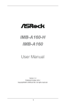
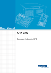
USER MANUAL BOX PC INEOS 800 User Manual Version 1.0 December 2012 Copyright Notice This document is copyrighted, 2012. All rights are reserved. The information contained in this document is subject to change without notice in advance. We make no warranty of any kind with regard to this material, including, but not limited to, the implied warranties of merchantability and fitness for a particular purpose. We shall not be liable for errors contained herein or for incidental or consequential damages in connection with the furnishing, performance, or use of this material. This document contains proprietary information that is protected by copyright. All rights are reserved. No part of this document may be photocopied, reproduced or translated to another language without the prior written consent of the manufacturer. Trademark Intel® and Pentium® are registered trademarks of Intel® Corporation. Microsoft® and Windows® are registered trademarks of Microsoft Corporation. Other trademarks mentioned herein are the property of their respective owners. ii Safety IMPORTANT SAFETY INSTRUCTIONS Please read these safety instructions carefully and keep this User's Manual for later reference. Ensure to follow all warnings and instructions marked on the product. Never open the equipment. For safety reasons, the equipment should be opened only by qualified service personnel. 1. Disconnect this equipment from any AC outlet before cleaning. Use a damp cloth. Do not use liquid or spray detergents for cleaning. 2. For plug-in equipment, the power outlet socket must be located near the equipment and must be easily accessible. 3. Put this equipment on a reliable surface during installation. Dropping it or letting it fall may cause damage. 4. The openings on the enclosure are for air convection. Protect the equipment from overheating. DO NOT COVER THE OPENINGS. 5. Make sure the voltage of the power source is correct before connecting the equipment to the power outlet. 6. Position the power cord so that people cannot step on it. Do not place anything over the power cord. 7. If the equipment is not used for a long time, disconnect it from the power source to avoid damage by transient overvoltage. 8. Please carry the unit with both hands, handle with care. 9. Properly maintain and clean the surfaces, use only approved products or clean with a dry applicator. 10. If one of the following situations arises, get the equipment checked by service personnel: a. The power cord or plug is damaged. b. Liquid has penetrated into the equipment. c. The equipment has been exposed to moisture. d. The equipment does not work well, or you cannot get it to work according to the user's manual. e. The equipment has been dropped and damaged. f. The equipment has obvious signs of breakage. 11. All cautions and warnings on the equipment should be noted. Keep this equipment away from humidity. Never pour any liquid into an opening. This may cause fire or electrical shock. This equipment shall not be used for life support system. iii IMPORTANT SAFETY STATEMENT This equipment has been tested and found to comply with the limits for a Class A digital device, pursuant to Part 15 of FCC Rules. These limits are designed to provide reasonable protection against harmful interference when the equipment is operated in a residential environment. This equipment generates uses and can radiate radio frequency energy. If not installed and used in accordance with this user's manual, it may cause harmful interference to radio communications. Note that even when this equipment is installed and used in accordance with this user's manual, there is still no guarantee that interference will not occur. If this equipment is believed to b e causing harmful interference to radio or television reception, this can be determined by turning the equipment on and off. If interference is occurring, the user is encouraged to try to correct the interference by one or more of the following measures: Any changes or modifications made to the equipment which are not expressly approved by the relevant standards authority could void your authority to operate the equipment. iv CE MARK This device complies with the requirements of the EEC directive 2004/108/EC with regard to “Electromagnetic compatibility” and 2006/95/EC “Low Voltage Directive”. FCC This device complies with part 15 of the FCC rules for a Class A digital device. Operation is subject to the following two conditions: (1) This device may not cause harmful interference. (2) This device must accept any interference received, including interference that may cause undesired operation. CAUTION ON LITHIUM BATTERIES If your computer is losing dramatic time or the BIOS configuration reset to default, the battery has no power. Do not replace battery yourself. Please contact a qualified technician or your retail. Contact your sales representative for technical support if you need additional assistance. This is because a danger of explosion will occur if the battery is replaced incorrectly. Input voltage rated 24 VDC,3.5 A maximum (DC Mode) Use a 3 V @ 195mA lithium battery (Model No.CR2032) LEGISLATION AND WEEE SYMBOL The box PC follows the national requirement to dispose unit. Business users should contact their supplier and check the terms and conditions of the purchase contract. This product should not be mixed with other commercial wastes for disposal. v Revision History Changes to the original user manual are listed below: Revision Description 1.0 vi Initial release Date December 2012 Table of Contents 1. Packing List.......................................................................................................................................... 1 1-1. Standard Accessories ..................................................................................................................... 1 2. System View ......................................................................................................................................... 2 2-1. Front and Side View ........................................................................................................................ 2 2-2. I/O View .......................................................................................................................................... 3 2.3. Dimensions...................................................................................................................................... 4 3. Components Replacing ....................................................................................................................... 5 3-1. HDD Replacing ............................................................................................................................... 5 3-2. Mounting Kit Disassembling ............................................................................................................ 6 3-3. Memory Replacing .......................................................................................................................... 7 4. Specification ........................................................................................................................................ 8 5. Jumper Setting ..................................................................................................................................... 9 5-1. Motherboard Layout ........................................................................................................................ 9 5-2. Connectors & Functions ................................................................................................................ 10 5-3. Jumper Setting .............................................................................................................................. 11 5-4. Pin Define............................................................................................................................ 12,13,14 6. Driver Installation............................................................................................................................... 15 6-1. Chipset Driver ............................................................................................................................... 15 6-2. Graphic Driver .......................................................................................................................... 16,17 6-3. Audio Driver .................................................................................................................................. 18 6-4. LAN Driver..................................................................................................................................... 19 Appendix: Driver Installation ................................................................................................................ 20 vii 1. PACKING LIST 1-1. Standard Accessories a. System box b. Power adapter 1 2. System View 2-1. Front and Side View 3 1 2 1. I/O placement 2. Ventilation holes 3. Mounting brackets Do not leave this equipment in an uncontrolled environment where the storage temperatures is below 10 °C(-14°F) or above 50°C (122° F). This may damage the equipment. 2 2-2. I/O View 2 1 k L a a a b c Item No. 1 2 a b c d e f g h i j k L 3 d e f g h Description Power & HDD LED indicators USB x 2 Line-Out DC Jack Cash Drawer Port Lan port USB x 2 12V powered USB x 1 VGA port COM Port x 4 (COM1 & COM2: with RI/5V/12V) Keyboard /Mouse port (P/S2 port) Power button Antenna hole HDMI port i j 2-3. Dimensions (Unit: mm) 4 3. Components Replacing 3-1. HDD Replacing 1. Turn system unit upside down and HDD door is located in the bottom. 2. Open the HDD door by unfastening the screw (x2). 3. Disconnect the HDD connectors (x2) and replace the HDD. 5 3-2. Mounting Kit Disassembling The box PC comes with wall mount brackets and if you do not need it. You can unfasten the screws (x4) by the side of box PC. Please follow the steps to secure your own wall-mount brackets with specified screws to fix the system box onto the wall. Specified screws:M4.0*0.7P Suggested length: over 5 mm Mounting brackets installation should be operated by professional technician, please contact the service technician or your retail if you need this service. Improper installation of mounting bracket can result in serious personal injury! 6 3-3. Memory Replacing 1. Unfasten 4 screws of mounting brackets and open the top cover. 2. Remove the top cover before memory replacement. 3. Use both fingers to pull the ejector clips out of the sides of the module. 4. Slide out to remove the memory module from the memory slot. 5. Slide the memory module into the memory slot and press down until the ejector clips click in place. Mounting brackets installation should be operated by professional technician, please contact the service technician or your retail if you need this service. Improper installation of mounting bracket can result in serious personal injury! 7 4. Specification System CPU Intel® Cedarview N2800 1.86GHz Front Side Bus 800/1066 MHz PCH NM10 Storage HDD Support 1 x 2.5” SATA HDD Memory DRAM 1 x 204-pin DDR3, 800/1066 MHz (Max:4GB) I/O Ports Display 1 x VGA D-SUB 15-pin 1 x HDMI port USB 2 x USB 2.0 port (Front side) 2 x USB 2.0 port (Rear side) 1 x powered USB 12V, Max.1A (Rear side) Gigabit Ethernet 1 x RJ45 LAN port with two LED indicators Cash Drawer 1 x RJ11 with 12V/24V jumper selectable power (Max.2A) COM 4 x D-SUB 9-pin port COM1 & COM2: with RI/5V/12V selectable by BIOS (Max.1A) Key Board / Mouse 1 x mini DIN 6-pin Line out 1 x Audio Jack Indicators 2 x LEDs (Power: Green & HDD: Red) Other Expansion Mini-PCIe Expansion for wireless module Internal USB 2 x USB 2.0 port pin header (available) Internal COM 1 x internal pin header 8 5. Jumper Setting 5-1. Motherboard Layout 9 8 22 11 26 J1 28 CD_PWR1 1 20 27 JSATA2 2 7 10 29 3 4 23 5 25 CMOS1 6 17 14 16 12 13 15 24 21 9 19 18 5-2. Connectors & Functions No. 1 2 3 4 5 6 7 8 9 10 11 12 13 14 15 16 17 18 19 20 21 22 23 24 25 26 27 28 29 Connector SATA_PWR1 SATA_PWR2 USB1 USB2 USB3 USB4 USB5 SPK_OUT1 LINE_OUT1 MSR1 SYS_FAN1 VGA1 LPC1 COM1 COM2 COM3 COM4 COM5 LED1 RJ1 J2 DC_IN1 HDMI1 KBMS1 CMOS1 J1 JSATA2 CD_PWR1 PUSB1 Purpose SATA1 Power SATA2 Power USB1 Header USB2 Header USB3 Header USB4 Header USB5/USB6 Connector Speaker Out Line Out PS2 Mouse Header System Fan Header VGA Header Low Pin Count Header COM1 Connector COM2 Connector COM3 Header COM4 Header COM5 Header LED Panel Header CD/LAN JACK Status LED header DC JACK HDMI Connector PS2 KB/MS Connector CMOS Clear Header Blight Select SATA2 Power ON/OFF Cash Drawer VCC Select Power USB Connector 10 5-3. Jumper Setting CMOS setting (No. 25 referring to 5-2 table) Manufacturer Default Setting : Monitor brightness setting (No. 26 referring to 5-2 table) Manufacturer Default Setting : SATA2 power setting (No. 27 referring to 5-2 table) Manufacturer Default Setting : Cash drawer VCC select (No. 28 referring to 5-2 table) Manufacturer Default Setting : 11 5-4. Pin Define (referring to 5-2 table) No. 1 & 2 SATA_PWR1,SATA_PWR2 1 12V 2 Ground 3 Ground 4 VCC5 No. 3,4,5 & 6 USB1,USB2,USB3,USB4 1 2 3 4 No. 8 USB_PWR USBN USBP Ground SPK_OUT1 1 2 3 4 No. 9 SPK_R+ SPK_RSPK_LSPK_L+ LINE_OUT1 1 2 3 4 No. 10 LOUT_R LOUT_JD Ground LOUT_L MSR1 1 2 3 4 5 6 5V_PS2 KB_DATA NC KB_CLK KB_EN Ground No. 12 VGA1 1 3 5 7 9 RED GREEN BLUE HSYNC VSYNC 2 4 6 8 10 DDC_DATA DDC_CLK VCC5 Ground Ground 12 No. 13 LPC1 1 3 5 7 9 Clock PCIRST LFRAME LAD3 LAD2 2 4 6 8 10 LAD1 LAD0 VCC3 Ground Ground No. 16, 17 & 18 COM3,COM4,COM5 1 3 5 7 9 DCD RXD TXD DTR Ground 2 4 6 8 10 DSR RTS CTS RI Key No. 19 LED1 1 3 5 7 9 11 SLP5_L SUSLED# 3VSB SDA PWRBTN VCC5 No. 20 RJ1 1 2 3 4 5 4 13 GND Data_Out0 Data_In0 Power Data_Out1 GND 2 4 6 8 10 12 Ground SATALED LANLED SCK Ground OSD_INT_L No. 21 J2 1 3 5 7 9 VCC3 PWRLED+ PWRBTN VCC3 GND 2 4 6 8 10 SATALED PWRLEDGND GND Key 14 6. Drivers Installation Installing Windows 7 32bit Device Driver 6-1.Chipset Driver Start chipset driver installing process by clicking file “infinst_autol” of folder “Chipset”. Installing process is as below (from left to right) 15 6-2. Graphic Driver Start graphic driver installing process by clicking file “Win7” of folder “Graphic”. 16 Installing process is as below (from left to right). 17 6-3. Audio Driver Start audio driver installing process by clicking file “Vista_Win7_Win8_R270”of folder “Audio”. Installing process is as below (From left to right). 18 6-4. LAN Driver Start LAN driver installing process by clicking file “setup” of folder “LAN”. Installing process is as below. 19 Appendix: Drivers Installation To download the most recent drivers and utilities, and obtain advice regarding the installation of your equipment, please visit the AURES Technical Support Website: www.aures-support.fr (French) www.aures-support.fr/UK (English) www.aures-support.fr/GE (German) 20