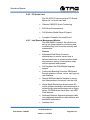
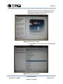
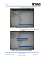
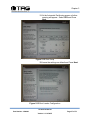
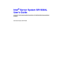
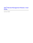
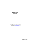
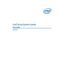
1
SV-2003-X2 Server Operations Manual
TAG
22355 TAG Way
Dulles, VA
20166
Operations Manual
1 Copyright © 2008 Technology Advancement Group®, Inc.
(TAG®)
All rights reserved. This publication and its contents are proprietary to TAG. No part of
this publication may be reproduced in any form or by any means without the written
permission of TAG, 22355 TAG Way, Dulles, Virginia 20166-9310.
TAG has made every effort to ensure the correctness and completeness of the material
in this document. TAG shall not be liable for errors contained herein. The information in
this document is subject to change without notice. TAG makes no warranty of any kind
with regard to this material, including, but not limited to, the implied warranties of
merchantability and fitness for a particular purpose.
1.1
Trademarks
All trademarks, marks, names, or product names referenced in this publication are the
property of respective owners, and TAG neither endorses nor otherwise sponsors any
such products or services referred to herein.
SV-2003-X2 Server
Part Number: 1006446
Page 2 of 72
Version 1.0. 10/30/07
Operations Manual
2 About This Manual
2.1
Scope and Audience
This manual provides information on the SV2003-X2 Server. The SV-2003-X2 Server
allows for up to 8 cores in a 2U chassis as well
as up to 64GB of RAM. Each server features
(2) Dual Core LV Xeon processors to maximize
processing performance, while reducing power
dissipation. Each server is capable of handling
(2) Quad-Core Xeon processors.
The dual server suite meets military standards
such as shock, vibration, and humidity. TAG
built the SV-2003-X2 to relieve potential
problems with a single failing power supply and
to create a product that end users can rely on.
The SV-2003-X2 is ideal for transit case and
deployable situations where such high density
computing minimizes size, weight, and power.
2.1.1 Organization
This manual is divided into the following
chapters and appendix:
•
•
•
•
Chapter 1 Cautions and Warnings when
handling the SV-2003-X2 Server.
Chapter 2 provides detailed information on the
external and internal server components.
Chapter 3 provides procedures for replacing
Hot-Swappable and LRU components, as well
as for replacing or adding system memory.
Chapter 4 provides a high-level overview that
defines RAID, the advantages and
disadvantages of various RAID levels, and
guidelines to observe when implementing
RAID.
SV-2003-X2 Server
Part Number: 1006446
Page 3 of 72
Version 1.0. 10/30/07
Operations Manual
2.2
About TAG
2.2.1 Summary of Qualifications
Providing engineering services and solutions
for our national defense and homeland security
is a responsibility that we don't take lightly.
TAG is a recognized industry leader in
developing defense technologies and
advanced electronics that support some of the
most complex solutions for battlespace
information networks and management
systems in the world.
Our customers depend on our expertise to
translate functional requirements and
performance objectives into specific design
criteria for individual elements and subsystems that comprise larger mission critical
systems. For more than twenty years, we have
dedicated our experience in engineering to the
design of innovative rugged solutions for
military and government, and to providing a
wide range of enterprise services and
Information Assurance in support of the
Defense Information Systems Agency's (DISA)
Net-Centric initiatives.
2.2.2 Core Competencies
TAG designs, manufactures, and supports
advanced communications electronics as well
as integrates, operates, and supports the users
of defense communication and information
networks for several technology programs in
the United States and abroad. TAG has two
operating segments consisting of the Tactical
Systems and Information and Engineering
Services business units;
Tactical Systems provides mechanical,
electrical, and thermal engineering for the
design and development of MIL-STD certified
electronic data enabled systems that are built
for in-theater survivability and communication
capability over joint enterprise platforms such
SV-2003-X2 Server
Part Number: 1006446
Page 4 of 72
Version 1.0. 10/30/07
Operations Manual
as DSN, GIG, STEP, GBS, and JTRS. This
includes the custom ruggedization of
commercial-off-the-shelf (COTS) and nondevelopmental items (NDI). TAG's mechanical
engineering division designs and fabricates
custom hardened enclosures, using high
performance metal materials, to house and
protect a variety of sensitive devices and
controls. TAG's electrical engineering division
designs programmable power solutions and
advanced sensor technologies including digital
receivers, advanced digital signal processors
and thermal detection systems. TAG's thermal
engineering applies survivability techniques to
ensure systems and instruments are designed
to withstand harsh environmental conditions
encountered by land-based, airborne, and
shipboard system in operations
Information and Engineering Services provides
a wide range of customer support operations,
enterprise network and communications
engineering services combining the experience
and expertise required to achieve network and
communication interoperability for component
hardware and software elements. This includes
design, simulation, analysis, and testing of the
components or systems for the support of
command and control operations. Our team of
national security cleared network engineering
professionals provides planning support for
information systems, architectures, and
networks while developing strategies that lay
the groundwork for sound technical
foundations for programmatic plans. Our
expertise in analyzing, designing,
implementing, and managing network,
telecommunication and security solutions
addresses the full lifecycle approach to
providing mission oriented enterprise class
services.
SV-2003-X2 Server
Part Number: 1006446
Page 5 of 72
Version 1.0. 10/30/07
Operations Manual
Document Revision History
Date
02/14/2008
03/20/2008
Version
Number
1.0
1.1
Updated By
Alan Huckerby
Alan Huckerby
Description of
Changes
Author
Author
SV-2003-X2 Server
Part Number: 1006446
Page 6 of 72
Version 1.0. 10/30/07
Operations Manual
Table of Contents
Contents
1 Copyright © 2008 Technology Advancement Group®, Inc. (TAG®) ............................ 2 1.1 Trademarks ............................................................................................................ 2 2 About This Manual ....................................................................................................... 3 2.1 Scope and Audience .............................................................................................. 3 2.1.1 Organization ...................................................................................................... 3 2.2 About TAG .............................................................................................................. 4 2.2.1 Summary of Qualifications ................................................................................ 4 2.2.2 Core Competencies .......................................................................................... 4 3 Safety Instructions ....................................................................................................... 12 3.1 Types of warnings used in this manual ................................................................... 12 3.1.1 Safety Symbols and Labels ............................................................................... 12 3.1.2 Conventions ...................................................................................................... 12 4 Server Overview .......................................................................................................... 15 4.1 Product Information ................................................................................................ 15 4.2 SV-2003-X2 Server ................................................................................................ 15 4.2.1 Specifications .................................................................................................... 15 4.2.2 Additional Specifications ................................................................................... 16 4.2.3 Server Highlights ............................................................................................... 17 4.2.4 SV-2003-X2 Server ........................................................................................... 17 4.3 Server Components ................................................................................................ 17 4.3.1 Motherboard and Type ..................................................................................... 18 4.3.2 SV-2003-X2 Server Motherboard ...................................................................... 18 4.3.3 Connector and Component Locations ............................................................... 19 4.4 System Memory...................................................................................................... 20 4.4.1 Identifying System Memory ............................................................................... 20 4.5 TAG Approved BIOS .............................................................................................. 21 4.5.1 Common BIOS Settings .................................................................................... 21 4.6 Identifying your I/O Connectors .............................................................................. 24 4.7 Standard Server Components ................................................................................ 25 4.7.1 CD/DVD Drive ................................................................................................... 25 4.7.2 Dual-redundant, auto-sensing power supply ..................................................... 26 4.8 PCI I/O Expansion Cards ....................................................................................... 27 4.8.1 Adaptec PCI-Express RAID Controller .............................................................. 27 4.8.2 PCI Audio Card ................................................................................................. 28 4.8.3 Intel Remote Management Module ................................................................... 28 5 Procedures .................................................................................................................. 31 5.1 Installing Red Hat 4.5 for S5000PAL and Adaptec 3805 system ............................ 31 5.2 Server Startup ........................................................................................................ 50 5.3 Server Shutdown .................................................................................................... 50 5.3.1 BIOS Configuration for SV-2003-X3 .................................................................. 51
SV-2003-X2 Server
Part Number: 1006446
Page 7 of 72
Version 1.0. 10/30/07
Operations Manual
5.4 Upgrading Memory and Replacing Hot-Swap and LRU Components .................... 58 5.4.1 Preventing Static Electricity ............................................................................... 58 5.5 Replacing a Hot-Swap Power Supply Module ........................................................ 59 5.6 Replacing a Hot-Swap Hard Drive .......................................................................... 60 5.6.1 147GB SAS Hard Drive ..................................................................................... 61 5.7 Removing the Server Cover ................................................................................... 61 5.8 Adding or Replacing System Memory .................................................................... 62 5.8.1 Install system memory. ..................................................................................... 63 6 RAID ............................................................................................................................ 65 6.1 RAID Defined.......................................................................................................... 65 6.1.1 Reasons for RAID ............................................................................................. 66 6.1.2 RAID Level 0 ..................................................................................................... 66 6.1.3 RAID Level 1 ..................................................................................................... 66 6.2 Configuring RAID 1 ON ADAPTEC 3805 ............................................................... 68 6.2.1 72 SV-2003-X2 Server
Part Number: 1006446
Page 8 of 72
Version 1.0. 10/30/07
Operations Manual
List of Figures
Figure 4-1 SV-2003-X2 Server Components and Connectors (Front View) ................. 17 Figure 4-2 Server Mother Board .................................................................................... 18 Figure 4-3 Server Mother Board .................................................................................... 19 Figure 4-4 I/O Connectors ............................................................................................. 25 Figure 4-5 Slot-loading low-profile DVD±R (DL)/-RAM/CD-RW Drive ........................... 25 Figure 4-6 Hot-Swap Power Supply .............................................................................. 27 Figure 5-1 Confirm Boot order ....................................................................................... 31 Figure 5-2 Introductory Screen ...................................................................................... 32 Figure 5-3 Loading Drivers ............................................................................................ 32 Figure 5-4 Welcome Screen .......................................................................................... 33 Figure 5-5 Language Screen ......................................................................................... 33 Figure 5-6 Keyboard Selection ...................................................................................... 34 Figure 5-7 Search for previously installed installations.................................................. 34 Figure 5-8 Disk Partitioning Setup ................................................................................. 35 Figure 5-9 Disk Partition Warning ................................................................................. 35 Figure 5-10 Automatic partitioning ................................................................................ 36 Figure 5-11 Automatic Partitioning (Warning) ............................................................... 36 Figure 5-12 Disk Setup.................................................................................................. 37 Figure 5-13 Boot Loader Configuration ......................................................................... 37 Figure 5-14 Firewall Configuration ................................................................................ 38 Figure 5-15 Additional Language Support ..................................................................... 38 Figure 5-16 Time Zone Selection .................................................................................. 39 Figure 5-17 Set Root Password .................................................................................... 39 Figure 5-18 Set Root Password (Confirmation) ............................................................. 40 Figure 5-19 Package Installation Defaults ..................................................................... 40 Figure 5-20 About to Install ........................................................................................... 41 Figure 5-21 Installation .................................................................................................. 41 Figure 5-22 Still Installing Buttons are disabled. ........................................................... 42 Figure 5-23 Installation Complete ................................................................................. 42 Figure 5-24 System Check ............................................................................................ 43 Figure 5-25 Welcome .................................................................................................... 43 Figure 5-26 License Agreement .................................................................................... 44 Figure 5-27 Set Date and Time ..................................................................................... 44 Figure 5-28 Set Display Color and Resolution. ............................................................. 45 Figure 5-29 Set Color Depth ......................................................................................... 45 Figure 5-30 Display ....................................................................................................... 46 Figure 5-31 System User (Non Administrative) ............................................................. 46 Figure 5-32 Personal user Account ............................................................................... 47 Figure 5-33 Additional CDs ........................................................................................... 47 Figure 5-34 Finish Setup ............................................................................................... 48 Figure 5-35 Log In Screen............................................................................................. 48 Figure 5-36 Log in Screen ............................................................................................. 49 Figure 5-37 BIOS Setup ................................................................................................ 51
SV-2003-X2 Server
Part Number: 1006446
Page 9 of 72
Version 1.0. 10/30/07
Operations Manual
Figure 5-38 Processor Configuration............................................................................. 51 Figure 5-39 Processor Configuration............................................................................. 52 Figure 5-40 Memory Configuration ................................................................................ 52 Figure 5-41 ATA Controller Configuration ..................................................................... 53 Figure 5-42 Serial Port Configuration ............................................................................ 53 Figure 5-43 Floppy/USB Configuration.......................................................................... 54 Figure 5-44 PCI Configuration ....................................................................................... 54 Figure 5-45 System Acoustic Configuration .................................................................. 55 Figure 5-46 Security ...................................................................................................... 55 Figure 5-47 Server Management .................................................................................. 56 Figure 5-48 Boot Order. ................................................................................................ 56 Figure 5-49 Save Changes ........................................................................................... 57 Figure 5-50 Grounding Wrist Strap ............................................................................... 58 Figure 5-51 Hot-Swap of 2U Server Power Supply Module .......................................... 60 Figure 5-52 147GB SAS HDD (Removed from HD Carrier) .......................................... 61 Figure 5-53 DIMM Module Bank ................................................................................... 63 Figure 6-1 RAID Level 1 (Mirroring) .............................................................................. 67 Figure 6-2 Raid Setup Utility ......................................................................................... 68 Figure 6-3 Array Configuration Utility ............................................................................ 68 Figure 6-4 Create Array................................................................................................. 69 Figure 6-5 Select Both Drives ....................................................................................... 69 Figure 6-6 Highlight RAID ............................................................................................. 70 Figure 6-7 Array Properties ........................................................................................... 70 Figure 6-8 Array Properties ........................................................................................... 71 List of Tables
Table 4-1 Mother Server Board Components ................................................................ 20 SV-2003-X2 Server
Part Number: 1006446
Page 10 of 72
Version 1.0. 10/30/07
Operations Manual
Chapter 1
Cautions and Warnings.
Electronically distributed. Subject to user discretion when printed.
SV-2003-X2 Server
Part Number: 1006446
Page 11 of 72
Version 1.0. 10/30/07
Operations Manual
3 Safety Instructions
3.1
Types of warnings used in this manual
Read this manual thoroughly, paying special attention to
the cautions and warnings.
3.1.1 Safety Symbols and Labels
DANGER
WARNING
CAUTION
These warnings and cautions indicate
situations or practice that might result in
property damage.
3.1.2 Conventions
3.1.2.1 Important Messages
Important
messages
appear
where
mishandling of components is possible or when
work orders can be misunderstood. These
messages also provide vital information
associated with other aspects of system
operation. The word “important” is written as
“IMPORTANT,” both capitalized and bold and
is followed by text in italics. The italicized text
is the important message.
3.1.2.2 Warnings
Warnings appear where overlooked details
may cause damage to the equipment or result
in personal injury. Warnings should be taken
seriously. Warnings are easy to recognize. The
word “warning” is written as “WARNING,” both
capitalized and bold and is followed by text in
italics. The italicized text is the warning
message.
SV-2003-X2 Server
Part Number: 1006446
Page 12 of 72
Version 1.0. 10/30/07
Operations Manual
3.1.2.3 Cautions
Cautionary messages should also be heeded
to help you reduce the chance of losing data or
damaging the system. Cautions are easy to
recognize. The word “caution” is written as
“CAUTION,” both capitalized and bold and is
followed by text in italics. The italicized text is
the cautionary message.
3.1.2.4 Notes
Notes inform the reader of essential but noncritical information. These messages should be
read carefully as any directions or instructions
contained therein can help you avoid making
mistakes. Notes are easy to recognize. The
word “note” is written as “NOTE,”
SV-2003-X2 Server
Part Number: 1006446
Page 13 of 72
Version 1.0. 10/30/07
Operations Manual
Chapter 2
SV-2003-X2 Server.
Electronically distributed. Subject to user discretion when printed.
SV-2003-X2 Server
Part Number: 1006446
Page 14 of 72
Version 1.0. 10/30/07
Operations Manual
4 Server Overview
4.1
Product Information
This chapter provides an introductory overview
of the TAG family of rugged servers. TAG
servers are highly customizable; the specific
components vary depending on the mission
requirements. Your system may contain
components not described in this chapter. For
detailed information on these components,
refer to the manufactures website or contact
TAG Technical Support at
tech.support@tag.com.
TAG's rugged servers combine Intel®
technology with state-of-the-art mechanical,
thermal and electrical engineering to create
customized systems that perform above and
beyond end user or program specifications.
Our rugged servers are designed to meet and
exceed many MIL-STD requirements to ensure
survivability in the field.
4.2
SV-2003-X2 Server
4.2.1 Specifications
Chassis & power supply:
• 2U Heavy-duty, .090inch
Aluminum/Magnesium alloy, strain hardened
and stabilized rack-mount chassis
• Chassis is designed to EIA-310-D Standards
• 3.5”H x 19”W x 24”D
• Redundant, Hot-Swap, auto-sensing power
supplies
• Cooling system developed specifically for
harsh environments
• Front accessible on/off switches
•
Intelligent Fan Controller
Acoustically optimized, environmentally aware
•
Processor & Cache:
(2) Dual Core Intel Xeon 5138 CPU’s
Motherboard and On-board Features:
SV-2003-X2 Server
Part Number: 1006446
Page 15 of 72
Version 1.0. 10/30/07
Operations Manual
•
•
•
•
•
•
•
•
Intel 5000P chipset, 1333MHz FSB
On-board ATI graphics controller with 16MB
RAM
On-board SATA controllers
(2) 10/100/1000 Ethernet ports
One serial port (RJ-45 connection
(2) USB 2.0 ports front, (2) USB 2.0 ports rear
PS/2 Keyboard & Mouse port
Expandable to 32GB FBDIMM
System Components:
8GB FB DIMM
(2) 400GB Hot-Swap, removable SAS hard
drives with rugged metal carriers and receivers
• (2) Additional hard drive expansion bays
• PCI Audio card
• Intel remote server management module
• Low-profile DVD±RW(DL),-RAM,CD-RW drive
• PCI Express SAS RAID controller (Support for
RAID 0,1, and 5)
4.2.2 Additional Specifications
• Total Weight: 42lbs
• Input Voltage Range: 115 Vrms nominal, 98 to
138 Vrms (-15%, +20%)
• Input Frequency Range: 60 Hz nominal, 56.4
to 63.6 Hz (- 6%, + 6%)
• Maximum Operating Power: 494.4 Watts
• Maximum Operating Current: 4.12 Amps
• Typical Operating Power: 410.4 Watts
• Typical Operating Current: 3.42 Amps
• Idle Power: 367 Watts
• Idle Current: 3.059 Amps
• AC Input Power Connector: IEC 320
• PFC: .97 Typical
• Operating Temp Range: 0-50°C
• Non-Operating Temp range: -40-70°C
• Operating Humidity: up to 90% noncondensing
• Shock: Designed to meet MIL-STD-901D
Grade B
• Vibration: Designed to meet MIL-STD-167-1
•
•
SV-2003-X2 Server
Part Number: 1006446
Page 16 of 72
Version 1.0. 10/30/07
Operations Manual
4.2.3 Server Highlights
• The SV-2003-X2 is unlike any other server that
is currently on the market. The SV-2003-X2 is
ideal for use in deployable situations where the
product’s compact size, high density
computing, minimized size, weight, and power
make for a highly portable, rugged and reliable
system
• Designed to meet MIL-STD-901D, MIL-STD810F, MIL-STD-167, MIL-STD-461E, and MILSTD-740
• Contains an intelligent fan controller
(acoustically optimized, environmentally aware)
• The chassis is made of environmentally
protected 5052 aluminum-alloy strain hardened
and stabilized chassis
• Proven to function in extreme operating
temperature ranges
4.2.4 SV-2003-X2 Server
Figure 4-1 SV-2003-X2 Server Components and Connectors (Front View)
4.3
Server Components
This section provides an overview of the most
common components installed in TAG rugged
servers. Information is also provided on how to
identify specific components within your server.
For detailed information on the specific
components installed in your server, refer the
manufactures website.
SV-2003-X2 Server
Part Number: 1006446
Page 17 of 72
Version 1.0. 10/30/07
Operations Manual
4.3.1 Motherboard and Type
The version of an Intel server motherboard can
be determined by decoding the last three digits
of the board part number.
For example: For the product C44686-703, the
number following the "-" is as follows:
7 = Fabrication (FAB) Number
03 = Revision 3.
The board part number can be found on the
motherboard. The board part number can also
be determined by using Intel Server
Management software.
4.3.2 SV-2003-X2 Server Motherboard
Figure 4-2 shows the primary components of the motherboard.
Figure 4-2 Server Mother Board
SV-2003-X2 Server
Part Number: 1006446
Page 18 of 72
Version 1.0. 10/30/07
Operations Manual
4.3.3 Connector and Component Locations
Figure 4.3 shows the board layout of the server
board. Each connector and major component
is identified by a number or letter, and a
description is given below in Table 4.3.
Figure 4-3 Server Mother Board
SV-2003-X2 Server
Part Number: 1006446
Page 19 of 72
Version 1.0. 10/30/07
Operations Manual
Table 4-1 Mother Server Board Components
4.4
System Memory
The type and amount of system memory, or
RAM (random access memory), on your server
depends on the motherboard installed and how
it was configured.
4.4.1 Identifying System Memory
Refer to your Motherboard and Type on Page
19.” Once you have identified the
motherboard, TAG technical support can assist
you in determining the type and amount of
system memory in your system. See
“Contacting information on TAG on back page
of this manual for information on how to
contact Technical Support.
SV-2003-X2 Server
Part Number: 1006446
Page 20 of 72
Version 1.0. 10/30/07
Operations Manual
For information on replacing or upgrading your
system memory, refer to “Adding and
Replacing System Memory on page 58.”
4.5
TAG Approved BIOS
The BIOS (basic input/output system) is the
program stored on the CMOS that the server's
microprocessor uses to get the system started
after you turn it on. The BIOS also manages
data flow between the computer's operating
system and attached devices such as the hard
disk, video adapter, keyboard, and mouse.
CAUTION: The BIOS installed on your
server was loaded and tested with all the
devices initially installed in your system. If
you desire to have the BIOS updated,
consult TAG technical support in advance
as updates to your approved BIOS may
cause your system to become unstable or
inoperable.
4.5.1 Common BIOS Settings
Printer Parallel Port-Uni., Bi-directional, Disable, Enable, ECP, EPP
4.5.1.1 Printer Parallel Port Uni., Bi-Directional, Disable,
Enable, ECP, EPP.
Settings in the CMOS enable you to configure
a parallel port to use Enhanced Parallel Port
(EPP) or Enhanced Parallel Port (ECP). ECP.
EPP and ECP are bi-directional standards,
operate in 8-bit, and allow data transfer speed
of approximately 2 MB/s. Some of the main
differences are that ECP supports Direct
Memory Access (DMA) and data compression,
which enables higher transfer rates.
It is also possible to completely disable the
parallel port in the BIOS. Most BIOS' allow you
to set the DMA channel, when the port mode is
set to ECP.
SV-2003-X2 Server
Part Number: 1006446
Page 21 of 72
Version 1.0. 10/30/07
Operations Manual
4.5.1.2 Com / Serial Port
Most personal computers have two serial ports.
In the BIOS you can assign
COM1/COM2/COM3/COM4 to serial port 1 or
2.
Most BIOS' also allow you to set the I/O and
IRQ but this is mostly done automatically.
4.5.1.3 Hard Drives
Most modern BIOS' allow automatic detection
of disk parameters. The settings can be
individually configured for the primary master
and slave device and the secondary master
and slave device. The following are some of
the primary settings that apply to hard drives
as well as CD/DVD-ROM drives, tape backup
drive, etc.
•
•
•
•
•
•
•
•
•
•
Common disk types are:
User-defined Cylinders, Heads, Sectors (CHS)
values
Auto-automatically detects hard disks
parameters at every startup
1-46-predefined combinations of CHS values
CDROM-used for AT Attachment Packet
Interface (ATAPI) CD-ROM drives
ARMD-used for ATAPI ZIP and LS 120 drives
DVDROM
Size - Determines the capacity of the drive CHS
values
Number of Cylinders
Number of Heads
Number of Sectors
LBA (Large Block Addressing)-technology to
overcome the 528 MB limit
SV-2003-X2 Server
Part Number: 1006446
Page 22 of 72
Version 1.0. 10/30/07
Operations Manual
4.5.1.4 Boot Sector Virus
A common setting related to hard drives. When
enabled, the BIOS issues a warning
message/beep if an attempt is made to write to
the boot sector or partition table of a hard disk.
4.5.1.5 Memory
Parity adds an extra bit (odd or even) to the 8bit data-string to ensure data integrity in
memory modules. Its successor, ECC,
provides improved data integrity by adding
information about individual bits.
4.5.1.6 Boot Sequence
This setting is used to control the order that the
BIOS uses during the boot process to look for
a boot device from which to load the operating
system. For example:
•
•
•
CD
Floppy
Hard Disk
4.5.1.7 Date and Time
The Date and Time is set in the BIOS, stored in
CMOS, and maintained by CMOS battery.
4.5.1.8 Passwords
In most cases a user (startup) password and a
supervisor (setup) password can be set in the
CMOS. When a Setup password is required,
the computer will prompt for it when you try to
access the BIOS setup. When a Startup
password is configured, the computer will
prompt for it at every startup.
The CMOS password can be reset by
shortening the "CMOS restore to factory
defaults jumper" or by temporarily removing the
CMOS battery.
SV-2003-X2 Server
Part Number: 1006446
Page 23 of 72
Version 1.0. 10/30/07
Operations Manual
4.5.1.9 Plug and Play BIOS
Today's BIOS' are Plug and Play (PnP)-aware.
This means they are able to automatically
assign resources such as IRQ and DMA to
PnP devices.
Information about PnP devices is stored in a
separate area of non-volatile CMOS memory,
called the Extended System Configuration
Database (ESCD). Both the PnP BIOS and the
operating system can access this area and
communicate with each other about resource
settings assigned to PnP devices as well as
non-PnP devices. For example, when a fixed
interrupt request (IRQ) is manually assigned to
a particular device using Device Manager,
Windows will write this information to the
ESCD on shutdown thereby preventing the
BIOS from assigning the same IRQ to a PnP
device at startup.
You can also reserve IRQs for non-PnP
devices in the CMOS setup, this will prevent
the BIOS from assigning these reserved
resources to PnP devices, a common example
is a legacy sound card that needs IRQ 5.
4.5.1.10
Power Management
Modern motherboards provide Advanced
Configuration and Power Management
Interface (ACPI) settings such as wake-up,
power button function and standby/suspend
timers. These functions are configured in the
CMOS Setup.
4.6
Identifying your I/O Connectors
Figure4-4 shows a typical configuration of I/O
connectors. Your configuration may vary
depending on the motherboard installed in your
server.
SV-2003-X2 Server
Part Number: 1006446
Page 24 of 72
Version 1.0. 10/30/07
Operations Manual
Figure 4-4 I/O Connectors
4.7
Standard Server Components
The following sections provide information on
the standard system components installed on
TAG servers
4.7.1 CD/DVD Drive
The type of optical drive installed in your server
varies per configuration. Figure 4.5.
Figure 4-5 Slot-loading low-profile DVD±R (DL)/-RAM/CD-RW Drive
SV-2003-X2 Server
Part Number: 1006446
Page 25 of 72
Version 1.0. 10/30/07
Operations Manual
4.7.2 Dual-redundant, auto-sensing power supply
Power for all the equipment in the system is a
dual redundant Hot-Swap AC input Power
supply with an Input AC Voltage Range
of 115 Vrms nominal, 98 to 138 Vrms (-15%,
+20%).
Input Power Line Frequency
The system shall operate over the input power
frequency range of 60 Hz nominal, 56.4 to 63.6
Hz (- 6%, + 6%).
Power Connector
The AC input power connector is IEC 320
WARNING
Power supplies contain dangerous
voltages. Before attempting to work on any
power supply always unplug the device and
drain the power source by turning the
server on after the power supply has been
disconnected. Failure to follow these
instructions could result in serious injury
due to electrical shock.
To satisfy reliability requirements, TAG servers
are designed with Hot-Swappable power
supplies. If in the event of a power supply
module failure or if the power source fails and
only one module is receiving power, an audible
alarm sounds. For procedures on how to HotSwap a power supply module refer to the
Procedures Section of this manual. Replacing
a Hot-Swap power supply.
Although most TAG power supplies for the 1U
and 4U series servers are similar in physical
sizes, and physical characteristics, some
servers use smaller foot print power supplies.
Figure 4-11 shows a typical 4U Hot-Swap
power supply.
SV-2003-X2 Server
Part Number: 1006446
Page 26 of 72
Version 1.0. 10/30/07
Operations Manual
Figure 4-6 Hot-Swap Power Supply
NOTE: If your server has two power input
receptacles, then the server is equipped
with a redundant Hot-Swap power supply.
Section 5.8.
4.8
PCI I/O Expansion Cards
The following sections provide on overview of
the PCI I/O components that may be included
with your server. For detailed information on
these components, refer to the manufacturers'
websites, or contact TAG Technical Support at
tech.support@tag.com. For more information,
See back page of this document.
4.8.1 Adaptec PCI-Express RAID Controller
The Adaptec RAID 3805 is an 8-port controller
that supports SATA and SAS drives. It
features Adaptec RAID Code (ARC) with RAID
levels 0, 1, 1E, 5, 5EE, 6, 10, 50, 60, JBOD, as
well as Copy back Hot Spare and optional
Snapshot Backup. The card has 128MB of
DDR2 memory.
SV-2003-X2 Server
Part Number: 1006446
Page 27 of 72
Version 1.0. 10/30/07
Operations Manual
4.8.2 PCI Audio Card
The SV-2003-X2 server carries a PCI Sound
Blaster 24 –bit Audio card with:
•
Patented CMSS 3D Audio Technology
•
EAX Music Enhancements
•
Full Windows Media Player 9 Support
•
Complete Cinematic Surround Sound
4.8.3 Intel Remote Management Module
The Intel RMM2 is used for the initial server
set-up, on-going production monitoring and
troubleshooting, and for server recovery and
maintenance.
Features
•
Embedded Web Server Connects
administrators to remote servers over a
secured connection to monitor system health
and perform a variety of maintenance tasks
with a supported web browser
•
Soft Keyboard via KVM Multiple language
support
•
Customized Branding Promotes OEM brand
through selection of icons, colors, and logos on
user interface
•
Remote KVM provides full keyboard, mouse,
and video access to the server over the LAN
•
Virtual Media Redirection allows remote OS
and/or software installation and maintenance to
access locally attached devices such as floppy
drives, CD-ROM drives, hard disks, and USB
Flash devices
•
Dedicated Network Segments manages traffic
onto dedicated networks for administrative and
bandwidth optimization
•
Interface Card
SV-2003-X2 Server
Part Number: 1006446
Page 28 of 72
Version 1.0. 10/30/07
Operations Manual
•
Security SSL, SSH, KVM Encryption,
authentication using LDAP or RADIUS
•
Remote Management, power control or reset
remote servers, monitor system sensors, and
view the hardware event log
•
SMASH CLP, WS-MAN
•
Email Alert sends system administrators
notifications via email of system changes
.
SV-2003-X2 Server
Part Number: 1006446
Page 29 of 72
Version 1.0. 10/30/07
Chapter 3
Chapter 3
Procedures.
Electronically distributed. Subject to user discretion when printed.
SV-2003-X2 Server
Part Number: 1006446
Page 30 of 72
Version 1.0. 10/30/07
Chapter 3
5 Procedures
The procedures within this Chapter contain
relevant information to ensure your SV-2003X2 Server maintains its maximum performance
potential.
5.1
Installing Red Hat 4.5 for S5000PAL and Adaptec 3805 system
1. Make sure that the supplied floppy is in a USB
floppy drive and attached to the system; be sure
the DVD is in the DVD-ROM.
2. With the hard drives set in RAID, enter BIOS and
confirm the boot order: [IDE PM:
MATSHITACD...], [AAR-3805 PCI-E RAI...], [IBA
GE Slot 0500 v...], [Y-E DATAUSB-FDU ...],
[[EFI Shell]]. (Figure 5.1)
Figure 5-1 Confirm Boot order
3. Once the computer boots to the Red Hat
Enterprise Linux 4.5 main screen (Figure 5.2),
type the following command as written: Press
Enter.
SV-2003-X2 Server
Part Number: 1006446
Page 31 of 72
Version 1.0. 10/30/07
Chapter 3
This will trigger the automated format and install
onto the RAID. After the install is complete the
DVD will eject and boot into the Linux OS.
Figure 5-2 Introductory Screen
4. Press Enter
Figure 5-3 Loading Drivers
SV-2003-X2 Server
Part Number: 1006446
Page 32 of 72
Version 1.0. 10/30/07
Chapter 3
After the drivers have been installed you will see
the full welcoming screen that will allow you to
install the full version of Linux 4.5.
Figure 5-4 Welcome Screen
5. Press Next. This will take you to the language
screen.
Figure 5-5 Language Screen
SV-2003-X2 Server
Part Number: 1006446
Page 33 of 72
Version 1.0. 10/30/07
Chapter 3
6. At the language screen select English
(English) and Press Next.
Figure 5-6 Keyboard Selection
7. Select the appropriate keyboard selection and
press Next.
Figure 5-7 Search for previously installed installations
SV-2003-X2 Server
Part Number: 1006446
Page 34 of 72
Version 1.0. 10/30/07
Chapter 3
8. At the keyboard screen and after keyboard is
chosen the system will automatically search for
previously installed configurations. Press Next.
Figure 5-8 Disk Partitioning Setup
9. Select Automatic Partitioning and Press Next.
Figure 5-9 Disk Partition Warning
SV-2003-X2 Server
Part Number: 1006446
Page 35 of 72
Version 1.0. 10/30/07
Chapter 3
10. At the Disk Partitioning Warning Select YES
and Press Next.
Figure 5-10 Automatic partitioning
At the Automatic partitioning screen Select
“Remove all Partitions on this system.” Ensure
that both driver sda-139784 MB ADAPTEC RAID
stripe and Review (and modify if needed) the
partitions created are checked. Press Next.
Figure 5-11 Automatic Partitioning (Warning)
SV-2003-X2 Server
Part Number: 1006446
Page 36 of 72
Version 1.0. 10/30/07
Chapter 3
11. At the Automatic Partitioning screen a further
warning will appear. Select YES and Press
Next.
Figure 5-12 Disk Setup
12. Leave the settings on default and Press Next.
Figure 5-13 Boot Loader Configuration
SV-2003-X2 Server
Part Number: 1006446
Page 37 of 72
Version 1.0. 10/30/07
Chapter 3
13. Leave the settings on default and Press Next
Figure 5-14 Firewall Configuration
14. Check “Enable Fire Wall” Press Next.
Figure 5-15 Additional Language Support
15. At the “Additional Language Support” screen
Check English (USA). Press Next.
SV-2003-X2 Server
Part Number: 1006446
Page 38 of 72
Version 1.0. 10/30/07
Chapter 3
Figure 5-16 Time Zone Selection
16. At the “Time Zone Selection” screen Select
America/New York, Eastern Time. Press
Next.
Figure 5-17 Set Root Password
SV-2003-X2 Server
Part Number: 1006446
Page 39 of 72
Version 1.0. 10/30/07
Chapter 3
17. Enter and confirm account password. Must
enter Password as “Password” selection.
Press Next.
Figure 5-18 Set Root Password (Confirmation)
18. Confirm Root User password selection. Press
Next.
Figure 5-19 Package Installation Defaults
SV-2003-X2 Server
Part Number: 1006446
Page 40 of 72
Version 1.0. 10/30/07
Chapter 3
19. On the “Package Installation Default” screen
Select “Install Default Software Packages”.
Press Next.
Figure 5-20 About to Install
CAUTION: Once you click Next there is no
undo.
20. Press NEXT to begin installation.
Figure 5-21 Installation
SV-2003-X2 Server
Part Number: 1006446
Page 41 of 72
Version 1.0. 10/30/07
Chapter 3
21. Press Next
Figure 5-22 Still Installing Buttons are disabled.
Figure 5-23 Installation Complete
22. Remove all diskettes or CD ROMs. Press
REBOOT.
23.
SV-2003-X2 Server
Part Number: 1006446
Page 42 of 72
Version 1.0. 10/30/07
Chapter 3
Figure 5-24 System Check
Figure 5-25 Welcome
24. Press Next.
SV-2003-X2 Server
Part Number: 1006446
Page 43 of 72
Version 1.0. 10/30/07
Chapter 3
Figure 5-26 License Agreement
Check YES If you agree to the licensing
agreement. Press Next.
Figure 5-27 Set Date and Time
25. Set Date and Time for the system. Press Next.
SV-2003-X2 Server
Part Number: 1006446
Page 44 of 72
Version 1.0. 10/30/07
Chapter 3
Figure 5-28 Set Display Color and Resolution.
26. Press Next.
Figure 5-29 Set Color Depth
27. Change the Resolution to “1024 x 768” (Your
displays optional resolution. Default is 1024
x 768.). Press Next.
SV-2003-X2 Server
Part Number: 1006446
Page 45 of 72
Version 1.0. 10/30/07
Chapter 3
Figure 5-30 Display
28. Select Color display and Resolution. Press
Next.
Figure 5-31 System User (Non Administrative)
29. Press Next.
SV-2003-X2 Server
Part Number: 1006446
Page 46 of 72
Version 1.0. 10/30/07
Chapter 3
Figure 5-32 Personal user Account
30. Create a Personal User Account. Click
Continue and Press Next.
Figure 5-33 Additional CDs
31. Installation as required. Press Next.
SV-2003-X2 Server
Part Number: 1006446
Page 47 of 72
Version 1.0. 10/30/07
Chapter 3
Figure 5-34 Finish Setup
32. Press Next
Figure 5-35 Log In Screen
33. Enter User name.
SV-2003-X2 Server
Part Number: 1006446
Page 48 of 72
Version 1.0. 10/30/07
Chapter 3
Figure 5-36 Log in Screen
34. Enter Password. Installation Complete.
SV-2003-X2 Server
Part Number: 1006446
Page 49 of 72
Version 1.0. 10/30/07
Chapter 3
5.2
Server Startup
1. Check to make sure that all the cables are
seated and connected correctly to the back of
the unit such as keyboard, mouse, monitor
VGA cable and both power cables.
2. Then Press the power switch ON to start the
computer (power switch is located in the front
of the unit)
3. Once the unit starts, System will go thru Power
On self Test (POST) (no action is required at
this time)
4. At windows dialog box press Ctrl, Alt, Delete
at once to login
5. Type in the correct user name and password
and then press enter to login
6. Once the operator is logged on to the unit they
could use the computer as they wish.
NOTE: Assuming the server is not
connected to any network.
5.3
Server Shutdown
1. The operator needs save any data that is
needed to be saved and then close application
2. Once all data is save and applications are
closed, click on Start menu, select shutdown
and then click OK to shutdown the computer.
SV-2003-X2 Server
Part Number: 1006446
Page 50 of 72
Version 1.0. 10/30/07
Chapter 3
5.3.1 BIOS Configuration for SV-2003-X3
1. On the Main page, change Quiet Boot to
[Disable]. Set the System date and time.
(Figure 5-11).
Figure 5-37 BIOS Setup
2. No changes for Processor Configuration.
(Figures 5-12 & 5-13)
Figure 5-38 Processor Configuration
SV-2003-X2 Server
Part Number: 1006446
Page 51 of 72
Version 1.0. 10/30/07
Chapter 3
Figure 5-39 Processor Configuration
3. No changes for Memory Configuration. (Figure
5-14)
Figure 5-40 Memory Configuration
SV-2003-X2 Server
Part Number: 1006446
Page 52 of 72
Version 1.0. 10/30/07
Chapter 3
4. No changes for ATA Controller Configuration.
(Figure 5-15)
Figure 5-41 ATA Controller Configuration
5. No changes for Serial Port Configuration.
(Figure 5-16)
Figure 5-42 Serial Port Configuration
SV-2003-X2 Server
Part Number: 1006446
Page 53 of 72
Version 1.0. 10/30/07
Chapter 3
6. No changes for USB Configuration. (Figure 517)
Figure 5-43 Floppy/USB Configuration
7. No changes are necessary for PCI
Configuration. (Figure 5-18)
Figure 5-44 PCI Configuration
SV-2003-X2 Server
Part Number: 1006446
Page 54 of 72
Version 1.0. 10/30/07
Chapter 3
8. No changes for System Acoustic and
Performance Configuration. (Figure 5-19)
Figure 5-45 System Acoustic Configuration
9. No changes for Security. (Figure 5-20)
Figure 5-46 Security
10. No changes for Server Management. (Figure
5-21)
SV-2003-X2 Server
Part Number: 1006446
Page 55 of 72
Version 1.0. 10/30/07
Chapter 3
Figure 5-47 Server Management
11. Set boot order as follows: DVD (IDE PS), RAID
(AAR-3805), LAN (IBA GE) and finally the EFI
Shell. (Figure 5.22).
Figure 5-48 Boot Order.
SV-2003-X2 Server
Part Number: 1006446
Page 56 of 72
Version 1.0. 10/30/07
Chapter 3
12. Select Save changes and Exit.. (Figure 5-23)
Figure 5-49 Save Changes
SV-2003-X2 Server
Part Number: 1006446
Page 57 of 72
Version 1.0. 10/30/07
Chapter 3
5.4
Upgrading Memory and Replacing Hot-Swap and LRU
Components
5.4.1 Preventing Static Electricity
This section provides procedures for replacing
all Hot-Swappable and LRU components,
including procedures for replacing or adding
system memory.
The components inside your computer are
extremely sensitive to static electricity, also
known as electrostatic discharge (ESD). ESD
can permanently damage electrostatic
discharge-sensitive components in your server.
To prevent ESD damage, follow these
guidelines before opening the server case:
1. Turn off the server and unplug the power cord
before opening the case.
2. Wear a grounding wrist strap and attach it to
a bare metal part of the server, workbench, or
other grounded connection.
Figure 5-50 Grounding Wrist Strap
3. Do not insert any object into the vent holes on
the case or the power supply. Touch a bare
metal surface on the back of the computer, a
bare metal surface on your workbench, or
other grounded object before handing DIMMs
or other components.
SV-2003-X2 Server
Part Number: 1006446
Page 58 of 72
Version 1.0. 10/30/07
Chapter 3
•
•
•
5.5
Before working with computer components,
follow these guidelines:
Avoid static-causing surfaces such as carpeted
floors, plastic, and packing foam.
Remove components from their antistatic bags
only when you are ready to use them. Do not
lay components on the outside of antistatic
bags because only the inside of the bags
provide electrostatic protection. Always hold
memory modules and components by their
edges or their metal mounting brackets.
Avoid touching the edge connectors and
components on the cards. Never slide memory
modules or components over any surface.
Replacing a Hot-Swap Power Supply Module
Your TAG server was designed with the ability
to Hot-Swap a power supply module without
disconnecting system power. Refer to Figure 412 and the steps that follow to Hot-Swap a
power supply module.
NOTE: If you need to remove both
modules, you must shutdown the system,
unplug the power source from the unit and
drain the systems onboard battery by
pressing the on/off switch and holding it in
place for approximately 10 seconds to drain
any charge that might be retained by the
systems motherboard.
1. Obtain certified replacement module from TAG.
For more information on contact information
see document back page.
2. Depending on the series of your server, either
a retention bracket or filtering cover that is
secured with thumb screws will need to be
removed first.
NOTE: In some cases a screw driver
(Philips head) might be required to remove
a retention bar that is screwed into the
power supply.
SV-2003-X2 Server
Part Number: 1006446
Page 59 of 72
Version 1.0. 10/30/07
Chapter 3
3. Loosen the thumb screws on the desired
module to be replaced.
4. Depress the module safety latch and gently pull
the handle as shown in Figure 4-12.
Figure 5-51 Hot-Swap of 2U Server Power Supply Module
5. Slide the replacement module into the power
supply.
6. Press firmly and evenly on the power module
until you feel the module seat in the back of the
power supply.
5.6
Replacing a Hot-Swap Hard Drive
The system's hard drive Hot-Swap feature
enables you to remove a hard drive without
shutting down the operating system or turning
off the system power. The way in which you
remove a hard drive depends on the
application you are using and whether you are
replacing a drive, adding a new one, or
removing a drive permanently.
SV-2003-X2 Server
Part Number: 1006446
Page 60 of 72
Version 1.0. 10/30/07
Chapter 3
When you remove a drive using the Hot-Swap
operation, you need to stop the hard drive and
take it offline to remove the logical software
links to the hard drive, and to reconfigure the
file system so that it will now ignore the
removed drive. You might also have to
reconfigure your application software to
operate without the removed drive. Therefore it
is strongly recommended that you contact TAG
Technical Support at tech.support@tag.com
before attempting to Hot-Swap a hard drive.
For more information on contact information
see document back page.
5.6.1 147GB SAS Hard Drive
Figure 5-52 147GB SAS HDD (Removed from HD Carrier)
5.7
Removing the Server Cover
The location of the mounting screws securing
the server cover varies per server . To remove
the cover, use a Phillips screwdriver to remove
all screws from the sides and top of the cover.
SV-2003-X2 Server
Part Number: 1006446
Page 61 of 72
Version 1.0. 10/30/07
Chapter 3
NOTE: It is important to make note of the
location from which screws are removed
since different screw lengths may be used
to secure the cover.
CAUTION
It is not safe to operate TAG servers
without the cover in place. Failure to take
this precaution may result in personal
injury and system damage.
5.8
Adding or Replacing System Memory
This section lists the procedures for adding or
replacing system memory.
WARNING
Ensure that the system is powered-down
and all power sources have been
disconnected from the server prior to
removing or replacing system memory.
Failure to do so could result in serious
injury from electrical shock.
CAUTION
Printed circuit boards and hard drives
contain electronic components that are
extremely sensitive to static electricity.
Ordinary amounts of static from your
clothes or the work environment can
destroy components. Do not touch the
components or any metal parts without taking
proper antistatic precautions.
AG's rugged servers combine Intel® SV-2003X2® technology with state-of-the-art
mechanical, thermal and electrical engineering
to create customized systems that perform
above and beyond end user or program
specifications. Our rugged servers are
SV-2003-X2 Server
Part Number: 1006446
Page 62 of 72
Version 1.0. 10/30/07
Chapter 3
designed to meet and exceed many MIL-STD
requirements to ensure survivability in the field.
5.8.1 Install system memory.
Unlatch both DIMM socket levers, as shown in Figure 4-14.
Figure 5-53 DIMM Module Bank
1. Note the location of the alignment notch.
2. Align the notches on the new module with the
notches on the memory and press it firmly into
the bank.
NOTE: The tabs on the sides of the memory
module should secure the DIMM
automatically. When the DIMM locks into
place, you will hear a click.
SV-2003-X2 Server
Part Number: 1006446
Page 63 of 72
Version 1.0. 10/30/07
Chapter 4
Chapter 4
RAID.
Electronically distributed. Subject to user discretion when printed.
SV-2003-X2 Server
Part Number: 1006446
Page 64 of 72
Version 1.0. 10/30/07
Chapter 4
6 RAID
RAID is an acronym for Redundant Array of
Inexpensive (or Independent) Disks. This
section provides a high-level overview that
defines RAID, the advantages and
disadvantages of various RAID levels, and
guidelines to observe when implementing
RAID.
6.1
RAID Defined
RAID is a way of storing data on two or more
physical disks for the purpose of redundancy,
improved performance, or both. The combined
physical disks make up what is called an array.
This array appears on the host system as one
disk. For example, if you have physical disk 1
and physical disk 2, those two disks appear to
the host system as one disk.
RAID consists of different levels, which
determine how the data is placed in the array.
Each RAID level has specific data protection
and system performance characteristics. The
following are commonly used SCSI RAID
levels:
1. RAID Level 0: Striping, good performance, no
redundancy
2. RAID Level 1: Mirroring, one-to-one
redundancy
3. RAID Level 5: Striping with parity striped
across all drives; offers performance and
redundancy
4. RAID Level 10: Mirroring and striping; best
redundancy and best performance
5. RAID Level 50: Parity striped across all drives
in a mirrored set; redundancy and performance
You can manage RAID arrays with a RAID
controller (hardware RAID) or with software
alone (software RAID).
SV-2003-X2 Server
Part Number: 1006446
Page 65 of 72
Version 1.0. 10/30/07
Chapter 4
6.1.1 Reasons for RAID
Depending on how you implement RAID (which
RAID level you use), the benefits include one
or both of the following:
•
Faster performance: In RAID 0, 10, or 50
arrays, the host system can access multiple
disks simultaneously. This improves
performance because each disk in an array
has to handle only part of the request. For
example, in a two-disk array, each disk needs
to provide only its part of the requested data.
• Data protection: In RAID 1, 10, 5, and 50
arrays, the data is backed up either on an
identical disk (mirror) or on multiple disks
(parity disks). RAID 10 and 50 also allow the
host to access disks simultaneously.
6.1.2 RAID Level 0
RAID Level 0 is not redundant, hence does not
truly fit the "RAID" acronym. In Level 0, data is
split across drives, resulting in higher data
throughput. Since no redundant information is
stored, performance is very good, but the
failure of any disk in the array results in all data
loss. This level is commonly referred to as
striping.
6.1.3 RAID Level 1
See Figure 6-1 RAID Level 1 is commonly
referred to as mirroring with 2 hard drives. It
provides redundancy by duplicating all data
from one drive on another drive. The
performance of a Level 1 array is slightly better
than a single drive, but if either drive fails, no
data is lost. This is a good entry-level
redundant system, since only two drives are
required. However, since one drive is used to
store a duplicate of the data, the cost per
megabyte is high.
SV-2003-X2 Server
Part Number: 1006446
Page 66 of 72
Version 1.0. 10/30/07
Chapter 4
Figure 6-1 RAID Level 1 (Mirroring)
SV-2003-X2 Server
Part Number: 1006446
Page 67 of 72
Version 1.0. 10/30/07
Chapter 4
6.2
Configuring RAID 1 ON ADAPTEC 3805
1. When prompted, press Ctrl A to enter the RAID
menu. (Figure 6.2)
Figure 6-2 Raid Setup Utility
1. Select Array Configuration Utility from the
menu then press “Enter” (Figure 6.3).
Figure 6-3 Array Configuration Utility
SV-2003-X2 Server
Part Number: 1006446
Page 68 of 72
Version 1.0. 10/30/07
Chapter 4
3. Select Create Array from the menu and press
Enter. (Figure 6-4)
Figure 6-4 Create Array
2. Press the Space bar twice to select both
drives. Then press Enter to continue.
(Figure 6.5).
Figure 6-5 Select Both Drives
SV-2003-X2 Server
Part Number: 1006446
Page 69 of 72
Version 1.0. 10/30/07
Chapter 4
3. Highlight RAID 1(Mirror) press Enter.
(Figure 6-6
Figure 6-6 Highlight RAID
4. Press Enter to continue. (Figure 6.7)
Figure 6-7 Array Properties
SV-2003-X2 Server
Part Number: 1006446
Page 70 of 72
Version 1.0. 10/30/07
Chapter 4
5. Select Disable for Write Caching and press
Enter. Then select Quick Init and press
Enter twice to continue. (Figure 6-8)
Figure 6-8 Array Properties
6. A warning will appear, press Enter to create
the RAID.
SV-2003-X2 Server
Part Number: 1006446
Page 71 of 72
Version 1.0. 10/30/07
CONTACT
6.2.1
22355 TAG Way
Dulles, VA 20166
Tel: 1-800-824-8693
www.tag.com
Technical Support
USA 1-800-TAG-TECH
Outside USA
While every precaution has been taken
to ensure the accuracy and completeness
of this literature. TAG assumes
no responsibility and disclaims and liability
for damage resulting from use of this information
or for any errors or omissions.