1
AR700 Series Router
Hardware Reference
AR725
AR745
AR750S
AR750S-DP
AR770S
2
AR700 Series Router
AR700 Series Router Hardware Reference
Document Number C613-03087-00 Rev E.
© 2005-2006 Allied Telesis Inc. All rights reserved. No part of this publication may be
reproduced without prior written permission from Allied Telesis Inc.
Allied Telesis Inc. reserves the right to change specifications and other information in
this document without prior written notice. The information provided herein is subject
to change without notice. In no event shall Allied Telesis Inc. be liable for any incidental,
special, indirect, or consequential damages whatsoever, including but not limited to lost
profits, arising out of or related to this manual or the information contained herein, even
if Allied Telesis Inc. has been advised of, known, or should have known, the possibility
of such damages.
All company names, logos, and product designs that are trademarks or registered
trademarks are the property of their respective owners.
C613-03087-00 Rev E
Hardware Reference
3
Contents
Introduction ...................................................................................................... 4
Models Covered By This Reference .................................................................... 4
Where To Find More Information ...................................................................... 4
AR700 Series Routers ........................................................................................ 5
AR725 Router ................................................................................................... 6
Hardware Features ..................................................................................... 6
Power Supply ............................................................................................. 7
AR725 LEDs and what they mean ............................................................. 10
AR745 Router ................................................................................................. 11
Hardware Features ................................................................................... 11
Power Supply ........................................................................................... 13
AR745 LEDs and what they mean ............................................................. 15
AR750S Router ............................................................................................... 17
Hardware Features ................................................................................... 17
Power Supply ........................................................................................... 18
AR750S LEDs and what they mean ........................................................... 19
AR750S-DP Router .......................................................................................... 20
Hardware Features ................................................................................... 20
AT-PWR03 Power Supplies ........................................................................ 21
AR750S-DP LEDs and what they mean ..................................................... 23
AR770S Router ............................................................................................... 24
Hardware Features ................................................................................... 24
Power Supply ........................................................................................... 26
AR770S LEDs and what they mean ........................................................... 27
Online Documentation .................................................................................... 28
To Access Documentation ......................................................................... 28
AT-TFTP Server ................................................................................................. 29
Using Windows Terminal and Hyperterminal ................................................... 30
Router Start-up ............................................................................................... 33
Memory .......................................................................................................... 37
Random Access Memory (RAM) ................................................................ 37
Battery-Backed RAM (AR725, AR745, AR770S only) ................................. 39
Onboard Flash Memory ............................................................................ 39
CompactFlash (AR725, AR745 only) ......................................................... 41
Expansion Options .......................................................................................... 43
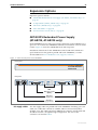
AR740 RPS Redundant Power Supply (AT-AR725, AT-AR745 only) ............. 43
SFP Ports (AR770S only) ............................................................................ 46
PICs and NSMs ......................................................................................... 46
PCI Accelerator Cards (PACs) .................................................................... 47
Asynchronous Interfaces ................................................................................. 50
Cables and Loopback Plugs ............................................................................. 51
RS-232 Terminal and Modem Cables ........................................................ 51
Loopback Plugs for Testing Interfaces ....................................................... 56
Test Facility ..................................................................................................... 58
Restricted Maintenance Procedures ................................................................. 60
Diagnostics ............................................................................................... 60
Lithium Battery Replacement .................................................................... 62
Contacting Us ................................................................................................. 62
C613-03087-00 Rev E
4
AR700 Series Router
Introduction
This Hardware Reference describes the hardware features of AR700 Series
router models, including information on PCI Accelerator Cards (PACs).
Hardware and installation information for Port Interface Cards (PICs) and
Network Service Modules (NSMs) can be found in their respective Quick
Install Guides and Hardware References.
Software and configuration This hardware reference does not cover software
configuration or software installation procedures. For information on software,
refer to your router’s Software Reference.
Models Covered By This Reference
This Hardware Reference includes information on the following models:
■
AR725 router
■
AR745 router
■
AR750S router
■
AR750S-DP router
■
AR770S router
Hardware Reference updates can be found at
www.alliedtelesis.com/support/software/ .
Where To Find More Information
The Documentation and Tools CD-ROM bundled with each router contains the
complete Document Set for your router and, where applicable, its expansion
options. The CD-ROM also includes tools for managing your router. These
documents can also be downloaded from the Support Site at
www.alliedtelesis.com/support/software/ .
The Document Set includes:
C613-03087-00 Rev E
■
The Installation and Safety Guide for your router, which provides safety and
statutory information and outlines how to install the router.
■
This AR700 Series Router Hardware Reference for your router, which provides
detailed information on the hardware features of AR routers.
■
The AR700 Series Router Software Reference for your router, which provides
detailed information on configuring the router and its software.
■
The Port Interface Card Quick Install Guide, which outlines the procedure for
installing PICs
■
The Port Interface Card Hardware Reference, which provides detailed
information on PICs.
■
The Network Service Module Quick Install Guide, which outlines the
procedure for installing an NSM
■
The Network Service Module Hardware Reference, which provides detailed
information on NSMs.
■
The AR740 RPS Quick Install Guide, which outlines the procedure for
installing a redundant power supply for the AR725 and AR745 AC models.
Hardware Reference
5
■
AT-TFTP Server for Windows, for downloading software versions.
■
Adobe Acrobat Reader, for viewing online documentation.
AR700 Series Routers
All AR700 Series routers include Ethernet ports, asynchronous ports, and PIC
bays; the AR750S, AR750S-DP and AR770S also have switch ports. PIC bays
add expansion flexibility by allowing the installation of PIC cards, which are
available with additional interfaces, such as ISDN (PRI E1/T1, BRI S/T),
synchronous, or asynchronous ports. The AT-AR745 routers also have an
expansion bay to accommodate a Network Service Module (NSM), which either
directly provides further interfaces, or provides multiple slots where additional
PIC interfaces can be added.
The AR725 and AR745 routers have a dedicated PCI Accelerator Card (PAC)
slot that accommodates special purpose PAC coprocessor cards. PAC cards
provide additional functionality or performance, such as compression or
encryption, through a high performance PCI bus, but do not add extra
interfaces. The AR750S and the AR750S-DP have built-in high performance
encryption processing.
AR700 Series models are distinguished by the number and types of ports and
presence or absence of an NSM bay and/or PCI Accelerator Card (PAC) slot.
Table 1: Interface configurations for AR700 Series routers
AR700 Series
Model
Ethernet
(Eth) Ports
Ethernet
Switch Ports
Asynchronous
Ports
PIC Bays
NSM
Bays
PAC Slot
AT-AR725
2 (10/100)
-
2
2
-
1
AT-AR745
2 (10/100)
-
2
2
1
1
AT-AR750S
2 (10/100)
5 (10/100)
1
2
-
built in
encryption
AT-AR750S-DP
2 (10/100)
5 (10/100)
1
2
-
built in
encryption
AT-AR770S
2 (fibre-optic SFP
or 10/100/1000)
4 (10/100/1000)
1
2
-
built in
encryption
C613-03087-00 Rev E
6
AR700 Series Router
AR725 Router
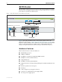
The AT-AR725 router consists of a base CPU card, enclosure and power supply.
The base CPU card supports dual 10/100 autonegotiating Ethernet LAN (eth)
ports and two asynchronous RS-232 ports.
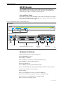
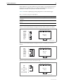
Figure 1: Front and rear panels of the AR725 Series router
Front Panel
AR725
STATUS
POWER
RUN
SYSTEM
COMPACT FLASH
CLEAR
SECURITY
ACTIVITY
Base LEDs
Rear Panel DC power inlet for RPS
Link
Data
ETH
Link
ETH
DISCONNECT POWER BEFORE INSTALLING/REMOVING PIC
PIC 1
AC POWER
100-240 VAC
50-60 Hz
1.0 A
Compact Flash
Two PIC bays with PICs installed
Data
RPS DC POWER
5V/5.5A
12V/1.0A
-12V/0.1A
Enterprise Router
L/A
L/A
PIC 1
PIC 0
ACT DAT ER CLR
ENGINE
BASE
100M
ETHERNET 1
100M
PIC 0
ETHERNET 0
PWR RUN SYS SEC
PORT 0
Asynchronous
ports
Ethernet ports
and LEDs
Power switch
AC power inlet
PORT 1
Mac engine LEDs
and base LEDs
725FRP
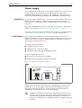
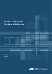
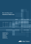
Figure 1 shows the AT-AR725 router’s front and rear panels (with a PIC
installed in each PIC bay). “AR725 LEDs and what they mean” on page 10 lists
functions of the AT-AR725’s LEDs. Additional rear panel LEDs may be present
if PICs are installed. Functions of LEDs on PICs are described in the Port
Interface Card Quick Install Guide and Port Interface Card Hardware Reference.
Hardware Features
Main hardware features of the AT-AR725 are:
C613-03087-00 Rev E
■
80 MHz RISC processor
■
1 MByte of EPROM
■
128 MBytes of synchronous DRAM (DIMM module)
■
16 MBytes of on-board flash memory
■
CompactFlash slot
■
128 KBytes of battery backed SRAM
■
2 high performance autonegotiating full duplex 10/100 Fast Ethernet LAN
ports
■
2 RS-232 asynchronous serial ports
■
2 PIC bays
■
A PAC compression/encryption card slot
■
Connector for a Redundant Power Supply (RPS)
■
-48 V DC power supply option
Hardware Reference
Asynchronous Ports
PIC Bays
CompactFlash slot
PAC slot
7
The two asynchronous serial ports can be used as general purpose ports for
terminals, printers, or modems. They are effectively identical and can be
independently configured. The default communications settings are:
•
9600 bps
•
8 data bits
•
1 stop bit
•
No parity
•
Hardware flow control
The chassis has two Port Interface Card (PIC) bays, which can accommodate any
combination of the following PICs:
■
AT-AR020 PRI E1/T1 PIC, one primary rate E1/T1 port
■
AT-AR021(S) BRI-S/T PIC, one basic rate ISDN S/T port
■
AT-AR021(U) BRI-U PIC, one basic rate ISDN U port
■
AT-AR022 ETH PIC, one Ethernet LAN AUI/10BASE-T port
■
AT-AR023 SYN PIC, one synchronous port with universal 50-way
AMPLIMITE connector
■
AT-AR024 ASYN4 PIC, four asynchronous ports with R-J45 connectors
■
AT-AR026 4ETH PIC, four 10BASE-T/100BASE-TX ports with RJ-45
connectors
■
AT-AR027 VoIP-FXS PIC, two Foreign Exchange Subscriber (FXS) ports
with RJ-11 connectors
The AT-AR725 has a CompactFlash slot on its front panel. For information on
CompactFlash, including a list of compatible flash cards, see “CompactFlash
(AR725, AR745 only)” on page 41.
The AT-AR725 router has a single PAC slot inside the chassis. When installed,
PACs provide hardware-based encryption and or compression capability via a
PCI interface. For information on PACs, including a list of compatible PACs,
see “PCI Accelerator Cards (PACs)” on page 47.
Power Supply
The AT-AR725 is available in two power supply configurations: a universal AC
model and a 48V DC model. The AC model includes an inlet for the AR740 RPS
(Redundant Power Supply). The AR740 RPS can be purchased separately, and
each unit supports up to two AT-AR725 or AT-AR745 routers.
AT-AR725 AC
AC models of the AT-AR725 have a universal AC input connector and a power
switch on their rear panels. A DB25 connector for an optional external
Redundant Power Supply (RPS), such as the AR740 RPS, is also located on the
rear panel.
Pin outs for the DB25 RPS connector, and cable specifications for RPS supply
cables, can be found in “Redundant Power Supply (RPS)” on page 8.
The router can monitor the PSU and the fan in both the router and the RPS. See
“AR725 LEDs and what they mean” on page 10 for more information.
C613-03087-00 Rev E
8
AR700 Series Router
AT-AR725-80 DC
The AT-AR725-80, designed for use by telecommunication carrier sites,
supports connection to a 48V DC power supply (in the range 39 to 60 V DC).
The DC model does not support an RPS connection, and does not support
monitoring of the main PSU or fan.
DC supply cable specifications:
■
Number of wires (cores): 3
■
Minimum size: 2.1 mm2 (14 AWG)
■
Minimum cable rating: 600 V, 90 degrees Celsius
DC power supply specifications:
■
48 V DC (38 V to 60 V DC is acceptable)
■
Either positive grounded or negative grounded
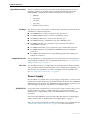
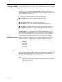
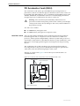
Figure 2: DC Power inlet terminals on an AR725
FOR CENTRALIZED DC
POWER CONNECTION,
INSTALL ONLY IN A
RESTRICTED AREA
3
DC POWER
1
38-60 VDC
,2A
Safety Safety information and instructions outlining how to connect an ATAR725-80 to a DC power supply can be found in the AR700 Series Router
Installation and Safety Guide. You should read these instructions before
attempting to connect the router to a DC power supply.
!
Redundant Power
Supply (RPS)
Caution Some interfaces that may be installed in the router are not
transformer isolated. This means they will be referenced to the frame
ground of the equipment and may be damaged if connected to an
interface on another piece of equipment which is at a different ground
potential.
AC models of the AT-AR725 can be used in conjunction with the AR740 RPS.
Each AR740 RPS can provide power supply and mains circuit redundancy for
up to two AT-AR725s or AT-AR745s. For more information on the AR740 RPS,
see “AR740 RPS Redundant Power Supply (AT-AR725, AT-AR745 only)” on
page 43.
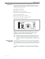
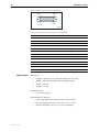
For connection to an AR740 RPS, the AT-AR725 router has a female DB25
connector on its rear panel (Figure 3). Pin outs for the connector are listed in
Table 2.
C613-03087-00 Rev E
Hardware Reference
9
Figure 3: DB25 female connector pinout for an RPS on the AT-AR725 rear panel
Pin 13
Pin 25
Pin 1
Pin 14
A740db25
Table 2: DB25 RPS power connector pin out on the AT-AR725
Pin
Function
Direction
1, 25
Keying
-
2, 14
+12 V
input
3-5, 15-17
+5 V
input
6-8, 18-20
0V
input
9
-12 V
input
10
VCC
output
11
Main PSU error
output
12
Main fan error
output
13
RPS disconnected
input
21
Sense 0 V
output
22
Sense +5 V
output
23
RPS PSU error
output
24
RPS fan error
input
C613-03087-00 Rev E
10
AR700 Series Router
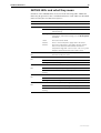
AR725 LEDs and what they mean
Functions of the AR725’s LEDs are shown in the following table. Additional
rear panel LEDs may be present if a PIC or NSM is installed. Functions of PIC
and NSM LEDs are described in their respective Hardware References.
LED
Front panel
Function
Rear panel
ETH
These LEDs give indications about the Ethernet interfaces.There are two LEDs for
each Eth port.
L/A (Link/Activity)
Lit green when the Ethernet interface is connected to a device (e.g., a hub), which
is generating link pulses. Blinks yellow when data is being transmitted or received
on the Ethernet interface.
100M
Lit when the Ethernet interface is in 100 Mbps mode.
PIC0/PIC1
Lit when a PIC is inserted in either PIC bay 0 or PIC bay 1 (one LED for each PIC).
BASE
These LEDs indicate the state of the main router unit.
Power
PWR
Lit when power is supplied and the router is switched on.
Run
RUN
Lit when the internal processor is executing code. If the processor stops for any
reason (a fault condition), then the LED will not be lit.
System
SYS
This LED is not normally lit. It is used to signal various system conditions (e.g.,
when the processor executes the reboot sequence). Generally it signals a possible
fault condition, but it is lit during a power-up or operator initiated reboot, and
remains lit until a software version has been loaded from flash memory.
Security
SEC
Lit when a user is logged in with SECURITY OFFICER privilege and the router is in
SECURITY MODE.
Lit when the compact flash card is accessed.
Do not remove the compact flash card when the LED is lit.
Activity
(Compact Flash)
Clear
C613-03087-00 Rev E
ENGINE
These LEDs give indications about PAC (PCI Accelerator Card), which can be
installed for encryption and/or compression purposes.
ACT
Lit when a PAC is installed in the PAC slot.
DAT
Lit when data is transferred to or from the PAC.
ERR
Lit when there is an error in the data transmission to or from the PAC.
CLR
Lit when a secure router has enabled PPP interfaces or Frame Relay circuits that are
configured to send clear text.
Hardware Reference
11
AR745 Router
The AT-AR745 router consists of a base CPU card, enclosure, and power
supply. The base CPU card supports two 10/100 autonegotiating Ethernet
LAN (eth) ports and two asynchronous RS-232 ports.
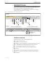
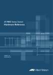
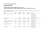
Front and Rear Panels
Front and rear panels of the AT-AR745 router with a Port Interface Card (PIC)
installed in each PIC bay, and an AT-AR040 4-PIC NSM installed in the NSM
bay, are shown in the following figure.
Figure 4: Front and rear panels of the AT-AR745 router
Front Panel
AR745
STATUS
RUN
SYSTEM
CLEAR
SECURITY
ACTIVITY
LEDs
Compact Flash
Rear Panel DC power inlet for RPS
0
Link
3
Data
ETH
2
ETH
0
ASYN
3
ASYN
3
RPS DC POWER
5V/5.5A
12V/1.0A
-12V/0.1A
Data
Two PIC bays with PICs installed
DISCONNECT POWER BEFORE INSTALLING/REMOVING PIC
PIC 1
AC POWER
100-240 VAC
50-60 Hz
1.0 A
Tx
1
SYN
Rx
Tx
SYN
Rx
NSM 0
SWAP
L/A
L/A
PIC 1
0
BASE
100M
ETHERNET 1
100M
ETHERNET 0
PIC 0
PWR RUN SYS SEC
Ethernet ports
and LEDs
Power switch
NSM bay with
AT-AR040 4-PIC NSM and PICs installed
PIC 0
ACT DAT ER CLR
ENGINE
HOT
SWAP
IN
AC power inlet
Link
POWER
Modular Enterprise Router
COMPACT FLASH
NSM Hot
Swap button
and LEDs
PORT 1
PORT 0
Asynchronous
ports
MAC engine
and base LEDs
745FRP
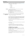
Hardware Features
Main hardware features of the AT-AR745 are:
■
80 MHz RISC processor
■
1 MByte of EPROM
■
128 MBytes of synchronous DRAM (DIMM module)
■
16 MBytes of on-board flash memory
■
CompactFlash slot
■
128 KBytes of battery-backed SRAM (NVS)
■
2 x 10/100 Mbps autonegotiating full-duplex Ethernet LAN (eth) ports
■
2 RS-232 asynchronous serial ports
■
2 PIC bays
■
1 hot swappable Network Service Module (NSM) bay
■
1 PAC slot for PAC compression and/or encryption cards
■
Connector for a Redundant Power Supply (RPS)
■
-48 V DC power supply option
C613-03087-00 Rev E
12
AR700 Series Router
PIC bays and NSM
bay
The AT-AR745 chassis has two PIC bays. A further four PIC bays can be added
if an AT-AR040 NSM is installed in the NSM bay.
The NSM bay allows one NSM to be installed in the chassis. NSMs either have
fixed ports (e.g., AT-AR041 and AT-AR042 BRI S/T NSMs) or PIC bays (e.g.,
the AT-AR040 4 PIC NSM). For detailed information on NSMs, see the Network
Service Module Hardware Reference.
The PIC bays and the 4-PIC NSM can accommodate combinations of the
following PICs (with a maximum of two E1/T1/PRI cards):
■
AT-AR020 PRI E1/T1 PIC, one primary rate E1/T1 port
■
AT-AR021(S) BRI-S/T PIC, one basic rate ISDN S/T port
■
AT-AR021(U) BRI-U PIC, one basic rate ISDN U port
■
AT-AR023 SYN PIC, one synchronous port with universal 50-way
AMPLIMITE connector
■
AT-AR024 ASYN4 PIC, four asynchronous ports with RJ-45 connectors
■
AT-AR027 VoIP-FXS PIC, two Foreign Exchange Subscriber (FXS) ports
with RJ-11 connectors
Recommendation AT-AR022 ETH PICs and AT-AR026 4ETH PICs are not
recommended for use in NSM PIC bays, as performance of these interfaces is
likely to be reduced and packet loss may occur. When used with an AR745
router, ETH PICs should be installed in the router’s PIC bay 0 or PIC bay 1.
Asynchronous Ports
PAC Slot
The two asynchronous serial ports can be used as general purpose ports for
terminals, printers or modems. They are effectively identical and can be
independently configured. The default communications settings are:
•
9600 bps
•
8 data bits
•
1 stop bit
•
no parity
•
hardware flow control
AT-AR745 routers have a single PAC slot inside the chassis. When installed,
PACs provide hardware-based encryption and or compression capability via a
PCI interface. For information on PACs, including a list of compatible PACs,
see “PCI Accelerator Cards (PACs)” on page 47.
!
C613-03087-00 Rev E
Caution PACs should only be installed by authorised service
personnel. Unauthorised opening of the router lid may cause danger of
injury from electric shock, damage to the router, and invalidation of
the product warranty.
Hardware Reference
13
Power Supply
The AT-AR745 is available in two power supply configurations: a universal AC
model and a 48 V DC model. The AC model includes an inlet for the
AR740 RPS (Redundant Power Supply). The AR740 RPS can be purchased
separately, and each unit supports up to two AT-AR745 or AT-AR725 routers.
AT-AR745 AC
AC models of the AT-AR745 have a universal AC input connector and a power
switch on their rear panels. A DB25 connector for an optional external
Redundant Power Supply (RPS), such as the AR740 RPS, is also located on the
rear panel.
Pin outs for the DB25 RPS connector, and cable specifications for RPS supply
cables, can be found in “Redundant Power Supply (RPS)” on page 14.
The router can monitor the PSU and the fan in both the router and the RPS. See
“AR745 LEDs and what they mean” on page 15 for more information.
AT-AR745-80 DC
The AT-AR745-80, designed for use by telecommunication carrier sites,
supports connection to a 48 V DC power supply (in the range 39 V to 59 V DC).
The DC model does not support an RPS connection, and does not support
monitoring of the main PSU or fan.
DC supply cable specifications:
■
Number of wires (cores): 3
■
Minimum size: 2.1 mm2 (14 AWG)
■
Minimum cable rating: 600 V, 90 degrees Celsius
DC power supply specifications:
■
48 V DC (38 V to 60 V DC is acceptable)
■
Either positive grounded or negative grounded
Figure 5: DC Power inlet terminals on an AR745
FOR CENTRALIZED DC
POWER CONNECTION,
INSTALL ONLY IN A
RESTRICTED AREA
3
DC POWER
1
38-60 VDC
,2A
Safety Safety information and instructions outlining how to connect an ATAR745-80 to a DC power supply can be found in the AR700 Series Router
Installation and Safety Guide. You should read these instructions before
attempting to connect the router to a DC power supply.
!
Caution Some interfaces that may be installed in the router are not
transformer isolated. This means they will be referenced to the frame
ground of the equipment and may be damaged if connected to an
interface on another piece of equipment which is at a different ground
potential.
C613-03087-00 Rev E
14
AR700 Series Router
Redundant Power
Supply (RPS)
AC models of the AT-AR745 can be used in conjunction with the AR740 RPS.
Each AR740 RPS can provide power supply and mains circuit redundancy for
up to two AT-AR745s or AT-AR725s. For more information on the AR740 RPS,
see “AR740 RPS Redundant Power Supply (AT-AR725, AT-AR745 only)” on
page 43.
For connection to an AR740 RPS, the AT-AR745 router has a female DB25
connector on its rear panel (Figure 6). Pin outs for the connector are listed in
Table 3.
Figure 6: DB25 female connector pinout for an RPS on the AT-AR745 rear panel
Pin 13
Pin 25
Pin 1
Pin 14
A740db25
Table 3: DB25 RPS power connector pin out on the AT-AR745
C613-03087-00 Rev E
Pin
Function
Direction
1, 25
Keying
-
2, 14
+12 V
input
3-5, 15-17
+5 V
input
6-8, 18-20
0V
input
9
-12 V
input
10
VCC
output
11
Main PSU error
output
12
Main fan error
output
13
RPS disconnected
input
21
Sense 0 V
output
22
Sense +5 V
output
23
RPS PSU error
output
24
RPS fan error
input
Hardware Reference
15
AR745 LEDs and what they mean
Functions of the AR745’s LEDs are shown in the following table. Additional
rear panel LEDs may be present if a PIC or NSM is installed. Functions of PIC
and NSM LEDs are described in their respective Hardware References.
LED
Front panel
Function
Rear panel
ETH
These LEDs give indications about the Ethernet interfaces.
LNK/ACT
Lit green when the Ethernet interface is connected to a device (e.g., a hub) which is
generating link pulses. Lit yellow indicates transmission or reception activity.
100M
Lit when the Ethernet interface is in 100 Mbps mode.
PIC0/PIC1
Lit when a PIC is inserted in either PIC bay 0 or PIC bay 1 (one LED for each PIC).
BASE
These LEDs indicate the state of the main router unit.
Power
PWR
Lit when power is supplied and the router is switched on.
Run
RUN
Lit when the internal processor is executing code. If the processor stops for any reason
(a fault condition), then the LED will not be lit.
System
SYS
Lit when the router or management software is malfunctioning. Flashes to indicate fan,
PSU, and RPS faults.
1 Flash: A router fan has failed.
2 Flashes: If an RPS is connected and RPS monitoring is enabled, an RPS fan has failed.
3 Flashes: If an RPS is connected, the router’s PSU (Power Supply Unit) has failed.
4 Flashes: If RPS monitoring is enabled, the RPS PSU has failed.
5 Flashes: If RPS monitoring is enabled, an RPS is not connected or is not operational
Security
SEC
Activity
(Compact Flash)
Clear
Lit when a user is logged in with SECURITY OFFICER privilege and the router is in
SECURITY MODE.
Lit when the compact flash card is accessed.
Do not remove the compact flash card when the LED is lit.
ENGINE
These LEDs give indications about a PCI Accelerator Card (PAC), which can be installed
for encryption and/or compression purposes.
ACT
Lit when a PAC is installed in the PAC slot.
DAT
Lit when data is transferred to or from the PAC.
ERR
Lit when there is an error in the data transmission to or from the PAC.
CLR
Lit when a secure router has enabled PPP interfaces or Frame Relay circuits that are
configured to send clear text.
NSM
These LEDs give indications about an NSM installed in the router.
Swap
Lit when the NSM and its PICs are powered down and can be hot swapped. Only lights
if the Hot Swap button has been pressed and the software version supports hot
swapping1.
In Use
Lit when an NSM is correctly installed. If the software version supports hot swapping,
it indicates that the NSM and its PICs are powered up and may not be swapped.
1. AT-AR021 (S) BRI-S/T, AT-AR021 (U) BRI-U, AT-AR022 ETH, AT-AR023 SYN, and AT-AR026 4ETH PICs can be hot swapped.
The AT-AR745 router automatically monitors its own power supply and fan,
and has the option of a redundant power supply. If a redundant power supply
(RPS) is attached, the AT-AR745 software can detect the presence of the RPS
and the state of its output voltages and fan. RPS monitoring, turned off by
default, can be turned on or off using the command:
set system rpsmonitor={on|off}
C613-03087-00 Rev E
16
AR700 Series Router
The show system command displays the state of the main power supply and
fan, and whether or not the RPS is being monitored. If RPS monitoring is
enabled, it also shows whether an RPS is connected, and the state of its output
voltage and fan.
When a fault occurs in the main power supply or fan, system LEDs on the
AT-AR745’s front and back panels are flashed in a pattern that identifies the
fault. If RPS monitoring is enabled, the system LEDs also flash to indicate
failures in the RPS connection, power supply or fan. Multiple faults are
indicated by cycling through each error code.
C613-03087-00 Rev E
Hardware Reference
17
AR750S Router
The AT-AR750S router has two 10/100 autonegotiating Ethernet (eth) ports,
one asynchronous RS-232 port, five Ethernet switch ports, and two Port
Interface Card (PIC) expansion bays.
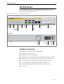
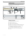
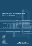
Figure 7: Front and rear panels of the AT-AR750S router
Front Panel
AR750S Secure VPN Router
ETHERNET
1
SWITCH PORTS
2
4
PIC1
CONSOLE
STATUS
ETHERNET
SWITCH PORTS
PIC
PWR
1
L/A
L/A
D/C
SYS
0
1
D/C
1
2
3
4
5
PIC0
0
0
Status
LEDs
Eth
LEDs
PIC
LEDs
1
5
3
ASYN0
Eth
ports
PIC BAYS
Asynchronous
port
PIC bays
Switch
ports
Switch
port LEDs
Rear Panel
Fan
vent
Power
inlet
Power
switch
Hardware Features
The main hardware features of the AT-AR750S are:
■
533 MHz PowerPC processor
■
64 MBytes of synchronous DRAM
■
16 MBytes of on-board flash memory, (1 MByte reserved for boot code)
■
High performance security engine (used for IPSec, SSL, 3DES, AES)
■
2 x 10/100 Mbps autonegotiating full duplex Ethernet (eth) ports
■
5 x 10/100 Mbps autonegotiating full duplex switch ports
■
1 RS-232 asynchronous DTE console port, with RJ45 connector
■
2 PIC bays
C613-03087-00 Rev E
18
AR700 Series Router
Asynchronous port
PIC bays
The asynchronous serial port (ASYN0) provides a general purpose port for
terminals, printers or modems. The port is wired as a DTE (Table 9 on
page 50). The default communications settings are:
•
9600 bps
•
8 data bits
•
1 stop bit
•
no parity
•
hardware flow control
The AT-AR750S chassis has two PIC bays, which can accommodate
combinations of the following PICs:
■
AT-AR020 PRI E1/T1 PIC, one primary rate E1/T1 port.
■
AT-AR021(S) BRI-S/T PIC, one basic rate ISDN S/T port.
■
AT-AR023 SYN PIC, one synchronous port with universal 50-way
AMPLIMITE connector.
■
AT-AR024 ASYN4 PIC, four asynchronous ports with RJ-45 connectors.
Power Supply
The AT-AR750S has a universal AC input connector and a power switch on its
rear panel. It operates with an input voltage in the range 100 VAC to 240 VAC.
C613-03087-00 Rev E
Hardware Reference
19
AR750S LEDs and what they mean
Functions of the AR750S LEDs are shown in the following table. Additional
LEDs may be present if a PIC is installed. Functions of PIC LEDs are described
in the Port Interface Card Hardware Reference.
LED
State
Function
Power/PWR
Green
The router is receiving power and the power switch is ON.
System/SYS
Off
Normal operation.
Amber
Lit briefly during router startup, or the router is
malfunctioning.
Flashing
There is a fault. To check the router’s fan speed,
temperature, and internal voltages, use the show system
command.
1 flash
The router fan has failed.
3 flashes
There is an internal power supply fault in the router.
6 flashes
The router temperature is too high or too low. Put the
router in a location that will maintain an ambient
temperature range of 0 ºC to 50 ºC (32 ºF to 122 ºF), with
adequate airflow around the router and its vents.
PIC0
PIC1
Green
A port interface card (PIC) is correctly installed and has
been detected by the router.
ETH0 / ETH1
Green
The Eth port has a 100 Mbps link.
L/A
Amber
The Eth port has a 10 Mbps link.
Flashing
Data is being transmitted on the Eth port.
ETH0 / ETH1
Green
The Eth port is operating at full duplex.
D/C
Amber
The Eth port is operating at half duplex.
Amber
flashing
There is a collision on the Eth port.
PORT 1..5
Green
The switch port has a 100 Mbps link.
L/A
Amber
The switch port has a 10 Mbps link.
Flashing
Data is being transmitted on the switch port.
PORT 1..5
Green
The switch port is operating at full duplex.
D/C
Amber
The switch port is operating at half duplex.
Amber
flashing
Collision on the switch port.
C613-03087-00 Rev E
20
AR700 Series Router
AR750S-DP Router
The AT-AR750S-DP router has two 10/100 Mbps autonegotiating Ethernet
(eth) ports, one asynchronous RS-232 port, five 10/100 Mbps Ethernet switch
ports, and two Port Interface Card (PIC) expansion bays.
The AT-AR750S-DP uses AT-PWR03 dual hot-swappable power supplies
(PSUs). You can install either AC or DC PSUs.
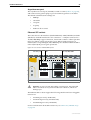
Figure 8: Front and rear panels of the AT-AR750S-DP router
Front Panel
ETHERNET
AR750S-DP Secure VPN Router
1
SWITCH PORTS
2
CONSOLE
4
PIC1
STATUS
ETHERNET
SWITCH PORTS
PIC
PSU 2
1
L/A
L/A
D/C
RESET
SYS
PSU 1
0
1
D/C
1
2
3
4
5
PIC0
0
0
Eth
LEDs
Reset
button
Status
LEDs
3
5
ASYN0
PIC BAYS
PIC
bays
Switch
ports
PIC
LEDs
Switch
port LEDs
1
Eth
ports
Asynchronous
port
Rear Panel
PSU Bay Two (PWR03 DC installed)
PSU Bay One (PWR03 DC installed)
PSU 2
AT-PWR03
AT-PWR03
DC Power Supply
40-60VDC
DC Power Supply
, 2.0A
40-60VDC
FOR CENTRALIZED DC POWER CONNECTION, INSTALL ONLY IN A RESTRICTED AREA
CAUTION: DISCONNECT ALL POWER AT SOURCE TO DISABLE SYSTEM POWER
, 2.0A
FOR CENTRALIZED DC POWER CONNECTION, INSTALL ONLY IN A RESTRICTED AREA
CAUTION: DISCONNECT ALL POWER AT SOURCE TO DISABLE SYSTEM POWER
Power
inlet
PSU 1
Run/standby switch
(DC PSU only)
Hardware Features
The main hardware features of the AT-AR750S-DP are:
C613-03087-00 Rev E
■
533 MHz PowerPC processor
■
64 MBytes of synchronous DRAM
■
16 MBytes of on-board flash memory, (1 MByte reserved for boot code)
■
2 x 10/100 Mbps autonegotiating full duplex Ethernet (eth) ports
■
5 x 10/100 Mbps autonegotiating full duplex switch ports
■
1 RS-232 asynchronous DTE console port, with RJ45 connector
■
2 PIC bays
■
High performance security engine (used for IPSec, SSL, 3DES, AES)
■
2 PSU bays compatible with dual hot-swappable, load sharing PSUs
■
Reset button
Hardware Reference
Asynchronous port
PIC bays
Restart with default
configuration
21
The asynchronous serial port (ASYN0) provides a general purpose port for
terminals, printers or modems. The port is wired as a DTE (Table 9 on page 50).
The default communications settings are:
•
9600 bps
•
8 data bits
•
1 stop bit
•
no parity
•
hardware flow control
The AT-AR750S-DP chassis has two PIC bays, which can accommodate
combinations of the following PICs:
■
AT-AR020 PRI E1/T1 PIC, one primary rate E1/T1 port.
■
AT-AR021(S) BRI-S/T PIC, one basic rate ISDN S/T port.
■
AT-AR023 SYN PIC, one synchronous port with universal 50-way
AMPLIMITE connector.
■
AT-AR024 ASYN4 PIC, four asynchronous ports with RJ-45 connectors.
To restart the router with the default configuration, either press the Reset
button on the front panel of the router, or use the command:
restart router config=none
This immediately restarts the router with the default configuration specified in
the boot.cfg file. The factory-loaded default configuration is shown in the
Installation and Safety Guide. If the file has been removed, the router restarts
with no configuration. We recommend leaving boot.cfg unchanged, so that
you can revert to the original configuration if necessary.
To return the router to the previous user configuration, restart the router by
using the command:
restart router
This restarts the router with the startup configuration file previously specified
by the command:
set config=filename
The restart reboot command or a power cycle also reload this user
configuration. For information about configuration files, see the Managing
Configuration Files and Software Versions chapter in the Software Reference.
AT-PWR03 Power Supplies
The AR750S-DP comes with the option of installing one or two AT-PWR03
power supplies. When two are fitted, they must be the same type of current,
either both AC or both DC.
The AR750S-DP should use only the AT-PWR03 power supply. Do not use any
other power supply to power this router.
You can create triggers to execute scripts when specific PSU events occur. For
more information, see the Trigger Facility chapter in the AR700 Series Router
Software Reference.
C613-03087-00 Rev E
22
AR700 Series Router
Safety Safety information and instructions outlining how to use an AT-PWR03
AC or DC power supply can be found in the AR750S-DP Router Installation and
Safety Guide. Read these instructions before attempting to install, remove or
power an AT-PWR03.
Hardware overview
The AT-PWR03 power supplies are hot-swappable and load share.
■
■
■
C613-03087-00 Rev E
Dimensions:
•
Height: 40.9 mm
•
Width: 193 mm
•
Depth: 130 mm
AC models:
•
Universal 100 VAC to 240 VAC, 50 Hz to 60 Hz input
•
Maximum continuous current draw: 1.6 A at 100 V, 1 A at 230 V
•
Maximum inrush current (cold start at 25 ºC/77 ºF): 50 A at 240 V, 25 A
at 115 V
DC models:
•
40 V to 60 V, 48 V nominal
•
Supports either positive grounded or negative grounded operation
•
Maximum continuous current draw: 2 A at 40 V
•
Maximum standby current: 100 mA
•
Run/standby switch
Hardware Reference
23
AR750S-DP LEDs and what they mean
Functions of the AR750S-DP LEDs are shown in the following table. Additional
LEDs may be present if a PIC is installed. Functions of PIC LEDs are described
in the Port Interface Card Hardware Reference.
LED
State
Status PSU 1..2 Green
Function
The router is ON, and is receiving power from the PSU
indicated by the LED.
Amber
There is a fan or power fault.
Off
Normal operation.
Amber
Lit briefly during router startup, or if the router is
malfunctioning.
Flashing
There is a fault. To check the router’s fan speed,
temperature, and internal voltages, use the show
system command.
3 Flashes
There is an internal power supply fault in the router.
6 Flashes
The router temperature is too high or too low.
7 Flashes
The router has both an AC and a DC power supply
connected to it. The router only supports dual power
supplies when the PSUs have the same current type.
ETH0 / ETH1
Green
The Eth port has a 100 Mbps link.
L/A
Amber
The Eth port has a 10 Mbps link.
Flashing
Data is being transmitted or received on the Eth port.
ETH0 / ETH1
Green
The Eth port is operating at full duplex.
D/C
Amber
The Eth port is operating at half duplex.
Amber flashing
There is a collision on the Eth port.
PORT 1..5
Green
The switch port has a 100 Mbps link.
L/A
Amber
The switch port has a 10 Mbps link.
Flashing
Data is being transmitted or received on the switch
port.
PORT 1..5
Green
The switch port is operating at full duplex.
D/C
Amber
The switch port is operating at half duplex.
Amber flashing
There is a collision on the switch port.
Green
A port interface card (PIC) is correctly installed and has
been detected by the router.
Status/SYS
PIC0
PIC1
C613-03087-00 Rev E
24
AR700 Series Router
AR770S Router
The AT-AR770S Secure VPN Router provides gigabit Ethernet and switch
ports, and can accommodate optional fibre-optic SFPs (small form-factor
pluggable modules) and Port Interface Cards (PICs).
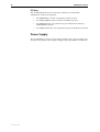
Figure 9: Front and rear panels of the AT-AR770S router
Switch
port LEDs
Front Panel
Switch
ports
SFP Eth
ports
ETHERNET
AR770S Secure VPN Router
1
SWITCH PORTS
1
2
CONSOLE
4
PIC1
STATUS
ETHERNET
PWR
SFP
SWITCH PORTS
10/100/1000
PIC
1
10/100/1000
L/A
L/A
D/C
SYS
0
1
D/C
0
1
1
2
3
4
PIC0
0
0
Status
LEDs
0
1
3
Asynchronous
port
PIC
LEDs
SFP Eth LEDs
10/100/1000
Eth LEDs
ASYN0
10/100/1000
Eth ports
PIC
bays
Rear Panel
POWER
ON
OFF
100-240 VAC
50/60 Hz
2.1 A
Fan
vent
Power
inlet
Power
switch
Hardware Features
The main hardware features of the AT-AR770S are:
C613-03087-00 Rev E
■
833 GHz PowerPC processor
■
128 MBytes of synchronous DRAM
■
512 kBytes of battery-backed SRAM (NVS)
■
32 MBytes of on-board flash memory, (1 MByte reserved for boot code)
■
High performance security engine (used for IPSec, SSL, 3DES, AES)
■
2 autonegotiating full duplex Eth ports — each port may be either
10/100/1000 Base T, or SFP sockets for fibre-optic SFPs
■
4 autonegotiating 10/100/1000 Mbps full duplex switch ports
■
1 RS-232 asynchronous DTE console port, with RJ-45 connector
■
2 PIC bays
Hardware Reference
25
Asynchronous port
The asynchronous serial port (ASYN0) is wired as a DTE (Table 9 on page 50),
and can be used as general purpose port for terminals, printers or modems.
The default communications settings are:
•
9600 bps
•
8 data bits
•
1 stop bit
•
no parity
•
hardware flow control
Ethernet SFP sockets
The router has two eth interfaces (labelled Ethernet): eth0 (labelled 0) and eth1
(labelled 1). Each Eth interface has two connectors — an RJ-45 connector for a
10/100/1000 Mbps copper connection, and an SFP socket for a fibre-optic SFP.
Only one of these can be operational at once. When an SFP transceiver is
installed, the corresponding 10/100/1000 Eth port is disabled. When the SFP is
removed, the RJ-45 port is again operational.
Figure 10: Eth1 SFP and 10/100/1000 options
eth1 SFP port
eth1 10/100/1000
eth1
ETHERNET
SWITCH PO
1
1
2
0
0
1
PIC
1
A
C
0
!
Warning Do not look into SFP cables or transceivers. Disconnected
fibres or connectors may emit invisible laser radiation, which can
damage eyes.
The Ethernet SFPs sockets support the following Small Form-factor Pluggable
transceivers:
•
AT-SPSX (previously AT-MG8SX)
•
AT-SPLX10 (previously AT-MG8LX10)
•
AT-SPZX80 (previously AT-MGZX)
For more information about SFP transceivers, see “SFP Ports (AR770S only)”
on page 46.
C613-03087-00 Rev E
26
AR700 Series Router
PIC bays
The AT-AR770S chassis has two PIC bays, which can accommodate
combinations of the following PICs:
•
AT-AR020 PRI E1/T1 PIC, one primary rate E1/T1 port
•
AT-AR021(S) BRI-S/T PIC, one basic rate ISDN S/T port
•
AT-AR023 SYN PIC, one synchronous port with universal 50-way
AMPLIMITE connector
•
AT-AR024 ASYN4 PIC, four asynchronous ports with RJ-45 connectors
Power Supply
The AT-AR770S has a universal AC input connector and a power switch on its
rear panel. It operates with an input voltage in the range 100 VAC to 240 VAC.
C613-03087-00 Rev E
Hardware Reference
27
AR770S LEDs and what they mean
The following table shows the functions of the AR770S LEDs. Additional LEDs
may be present if a PIC is installed. Functions of PIC LEDs are described in the
Port Interface Card Hardware Reference.
LED
State
Function
Status PWR
Green
The router is receiving power and is switched ON.
Status SYS
Off
Normal operation.
Amber
Lit briefly during router startup, or when the router
system is malfunctioning.
Flashing
There is a fault. To check the router’s fan speed,
temperature, and internal voltages, use the show
system command.
1 flash
The router fan has failed.
3 flashes
There is an internal power supply fault in the router.
6 flashes
The router temperature is too high or too low. Put the
router in a location that will maintain an ambient
temperature range of 0 ºC to 50 ºC (32 ºF to 122 ºF),
with adequate airflow around the router and its vents.
Green
The SFP Eth port has a 1000 Mbps link.
Green flashing
Data is being transmitted or received.
Amber
There is an SFP installed, but there is no link.
Amber flashing
There is a transmission fault at this SFP port.
Green
The Eth port has a 1000 Mbps link.
Amber
The Eth port has a 10 or 100 Mbps link.
Flashing
Data is being transmitted or received.
Green
The Eth port is operating at full duplex.
Amber
The Eth port is operating at half duplex.
Amber flashing
There is a collision on the Eth port.
Green
The switch port has a 1000 Mbps link.
Amber
The switch port has a 10 or 100 Mbps link.
Flashing
Data is being transmitted or received
Green
The switch port is operating at full duplex.
Amber
The switch port is operating at half duplex.
Amber flashing
There is a collision.
Green
A port interface card (PIC) is correctly installed and has
been detected by the router.
Ethernet
SFP 0..1
L/A
Ethernet
10/100/1000
0..1
L/A
Ethernet
10/100/1000
0..1
D/C
Switch Ports
10/100/1000
1..4
L/A
Switch Ports
10/100/1000
1..4
D/C
PIC 0..1
C613-03087-00 Rev E
28
AR700 Series Router
Online Documentation
This section provides a step-by-step guide to accessing the documentation on
the Documentation and Tools CD-ROM. Adobe Acrobat Reader must be
installed to view the online documentation.
To Access Documentation
To use the CD-ROM, follow these steps:
1.
Insert your router’s Documentation and Tools CD-ROM in the CD-ROM drive.
2.
If the CD browser menu does not appear.
Select "Run" from the Start Menu (Windows 98, 2000 or Windows XP).
Type d:\start.exe (where d: is the CD-ROM drive letter) and click OK.
3.
To view a document.
Click on the document title.
4.
To navigate around PDF documents.
Use the toolbar buttons, keyboard shortcuts, or commands from the
Document menu to page through the document.
Click on a bookmark, thumbnail or hypertext link to jump to a specific
section or topic.
Use the Search command to search for keywords or phrases.
For more information about using the Adobe Acrobat Reader, select
"Reader Guide" from the Help menu.
5.
To install any of the tools included on the CD-ROM.
Click on a link in the CD browser menu.
C613-03087-00 Rev E
Hardware Reference
29
AT-TFTP Server
This section provides information on how to access and use AT-TFTP Server.
AT-TFTP Server can be used to transfer configuration files as well as to
download software patches and versions.
To use AT-TFTP Server, follow these steps:
1.
If AT-TFTP Server has not yet been installed.
Install it now from the your router’s Documentation and Tools CD-ROM.
To install AT-TFTP server:
Choose AT-TFTP Server from the Start > Programs > Allied Telesis >
AT-TFTP Server menu.
2.
To set preferences for the AT-TFTP Server.
Select "Options" from the File menu to display the "Set Preferences" dialog
box.
The "Default file transfer directory" field specifies the directory that ATTFTP Server will read from or write to for file requests that do not include a
directory specification.
To prevent unauthorised access to private directories, enter a path name in
the "Restrict to directory" field. AT-TFTP Server will use only the specified
directory, even if file requests contain references to other directories.
Select "Read only" to prevent files being written to the PC. To use the PC to
archive router scripts created using the router's create config command,
select "Read Write".
Make any required changes and click "OK".
3.
To load a file from AT-TFTP Server to the router.
On a terminal connected to the router, type the command:
load method=tftp file=filename server=ipadd dest=flash
where filename is the name of the file to download and ipadd is the IP
address of the PC running AT-TFTP Server.
4.
To save a TFTP Server log.
Select "Save As" from the File menu.
C613-03087-00 Rev E
30
AR700 Series Router
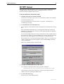
TFTP requests are logged to the AT-TFTP Server main window.
Using Windows Terminal and
Hyperterminal
You can use a PC running terminal emulation software as the manager console,
instead of a terminal. There are many terminal emulation applications
available for PCs, but the most readily available are the Terminal and
HyperTerminal applications included in Microsoft Windows 98, 2000, and
XP Professional. In standard Windows installations, HyperTerminal is
available from the Communications submenu.
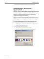
The key to successful use of terminal emulation software with the router is to
configure the software and router with matching communications parameters.
The following procedure can be applied to most terminal emulation programs.
Dialog boxes in the procedure are from Windows 2000 and XP Professional.
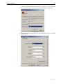
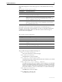
To configure Windows HyperTerminal for 2000 and XP Professional
1.
2.
C613-03087-00 Rev E
Start the program in Windows by doing one of the following:
•
Select Programs > Accessories > Communications > HyperTerminal.
•
Double-click the Hypertrm.exe icon.
In the Connection Description dialog box:
•
Enter a name for the connection, such as Admin.
•
Select an icon from the scrollable list and click the OK button.
Hardware Reference
31
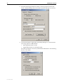
3.
In the “Connect using” field on the Connect To dialog box, select the COM
port on the PC used to connect to the router. and click the OK button.
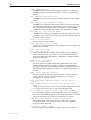
4.
In the COMn Properties dialog box, set port parameters as follows, and click
the OK button.
C613-03087-00 Rev E
32
AR700 Series Router
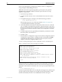
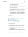
5.
From the main HyperTerminal window, select Properties from the File
menu. Click the Settings tab, and set the Properties dialog box as follows.
6.
Click ASCII Setup to display the ASCII Setup dialog box, and ensure the
following options are not selected:
•
Echo typed characters locally
•
Append line feeds to incoming line ends
Set other parameters as necessary and click the OK buttons on both dialog
boxes to close them.
C613-03087-00 Rev E
Hardware Reference
33
7.
Save the current session by selecting Save from the File menu on the main
HyperTerminal window. This creates a connection icon with the name you
assigned in the HyperTerminal group.
To use the configuration, double-click the connection icon. When the
HyperTerminal window appears, press the Enter key several times; the
router’s login prompt is then displayed.
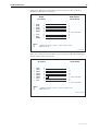
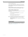
Router Start-up
At start-up, the manager can choose to run either the software version stored in
the flash boot block, or the software version in the flash file system specified by
the installation parameters previously set using the set install command.
All code is executed out of system RAM. At power-up the boot code is loaded
from the flash boot block to RAM. The boot code checks the installation
parameters then reloads RAM with the selected temporary, preferred, or default
install version (stored in the flash file system) and runs this code.
The version is uncompressed as it loads to RAM. This may take 10 to 30
seconds. At this point, any required patches are loaded from the flash file
system. Any patch is also uncompressed as it loads to RAM. This procedure
ensures that the code runs at maximum speed, and allows updates to be made
to the code. Updates can be downloaded over the network from a TFTP server
and stored in the flash file system until required at power-up.
To download software onto the router, see the Managing Configuration Files and
Software Versions chapter in the Software Reference.
All router software, patches, and configuration settings are stored as files in
flash memory. Typically, the following files will be present in the flash file
system:
■
The current installed software version. Additional software versions may
also be present.
■
The current installed patch, if any. Additional patches may also be present.
■
The command line help file for the command line interface (CLI). The
command help is stored in a separate text file, with extension .hlp. The
command help file is loaded with a software version.
■
The boot configuration script boot.cfg. The boot script contains standard
router commands (executed on start-up to configure the router).
■
Additional user-defined configuration scripts containing commands to
configure the router for different functions. These scripts are created using
the built-in editor, the add script command (in the Scripting chapter of the
Software Reference), or the create config command (in the Managing
Configuration Files and Software Versions of the Software Reference).
■
Other files required by the system.
Configuration information is stored in flash memory as configuration scripts.
These scripts contain standard router commands. When a configuration
command is entered at the command prompt from a terminal, terminal
emulation program, or Telnet session, the command alters the dynamic
configuration only; this is not saved over a power cycle. To ensure that
configuration changes resulting from such commands are retained across a
C613-03087-00 Rev E
34
AR700 Series Router
power cycle, the dynamic configuration must be saved as a configuration
script, using the create config command.
When the router starts up following either a power cycle or an operatorinitiated reboot (using the restart command), it performs the following
sequence of operations:
1.
Perform start-up self tests.
2.
Load the flash boot block version as the INSTALL boot into the router’s
RAM.
3.
Prompt the manager for changes to the default start-up procedure:
Force EPROM download (Y)?
The manager may press one of the keys listed in Table 4 on page 35 to
override the default installation procedure.
4.
Check the INSTALL information to determine which version to load and
run, according to the INSTALL parameters, and the manager’s response to
the previous prompt. If none of the keys in Table 4 on page 35 are pressed,
the INSTALL parameters determine which version and patch are loaded
and run.
5.
Load the required version specified by the INSTALL parameters from the
flash file system as the main boot.
6.
Start the router.
7.
Execute the boot configuration script, if one has been configured. (The boot
configuration script is either a configuration file set using the set config
command from the Managing Configuration Files and Software Versions
chapter, or the file boot.cfg file, if there is one.)
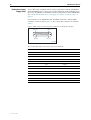
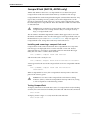
A series of start-up messages is sent to asyn0 (the console or terminal port).
Figure 11: Example of router start-up messages on an AR750S
INFO: Self tests beginning.
INFO: RAM test beginning.
PASS: RAM test, 65536k bytes found.
INFO: Self tests complete
INFO: Downloading router software.
Force EPROM download (Y) ?
INFO: Initial download successful
INFO: Initialising Flash File System.
INFO: IGMP packet trapping is active for IGMP snooping, L3FILT
is activated
INFO: Executing configuration script <flash:boot.cfg>
INFO: Router startup complete
login:
After the self tests are complete, the manager is given the option of forcing a
mandatory boot from the flash boot block version. The following message is
displayed on the terminal connected to the console port (asyn0) and the router
pauses:
Force EPROM download (Y)?
If a key is not pressed within a few seconds, the start-up process continues and
all steps in the start-up sequence are executed. Pressing selected keys on the
terminal immediately after the “Force EPROM download” message is
C613-03087-00 Rev E
Hardware Reference
35
displayed changes the router start-up process as described in the following
table.
Table 4: Router start-up sequence keystrokes
Pressing key...
Forces the router to...
(no key pressed) After a few seconds, the router startup process continues.
[Y]
Load the version, without any patches, from EPROM onto the RAM, and
run the full version. Go to step 6.
[S]
Load and run the version and patch determined by the INSTALL
parameters from the flash file system, ignoring any boot script or any
previous configuration stored in NVS.
[N]
Load from flash to RAM the version and patch determined by the INSTALL
parameters, and run using the current configuration stored in NVS (if
any), ignoring any boot script.
During the start-up process the router generates four different types of
messages. All messages are preceded by one of the words INFO, PASS, FAIL,
or ERROR. The meaning of these words in the context of the messages is
shown in the following table.
Table 5: Router start-up message classes
Message
Meaning
INFO
An informational message that an action has been taken by the system.
PASS
An informational message that a test has been completed successfully.
ERROR
An error message that a test has failed, but the system will continue to
operate.
FAIL
An error message that a fatal error condition has caused the system to
halt in an unrecoverable fashion.
WARNING
A serious error has occurred, which may indicate hardware failure.
The possible messages and their meanings are:
INFO: Self tests beginning.
The code loader tests are about to begin.
INFO: RAM test beginning.
The RAM tests are about to begin.
PASS: RAM test, 65536k bytes found.
The RAM test passed, and the indicated amount of memory was found
and will be used in the router.
ERROR: RAM test 5. Error address = 00345678.
A RAM test failed, at the given address. In the example, it was the fifth
test run. The RAM test repeats until it passes, so a number of messages
like this may appear. This fault means that the memory system is faulty.
If the fault continues, contact your distributor or reseller immediately.
INFO: BBR tests beginning.
The BBR tests are about to begin.
PASS: BBR test. Battery OK.
The BBR battery test passed.
C613-03087-00 Rev E
36
AR700 Series Router
ERROR: BBR Battery low.
The BBR battery test failed, indicating that the battery is running low.
The BBR system will need to be replaced. Contact your distributor or
reseller.
PASS: BBR test, 256k bytes found.
The BBR size/location test passed, with the indicated amount of BBR
found.
FAIL: BBR test. Error address = 12345678.
The BBR size/location test failed at the given location. The test at this
location failed, indicating the end of memory, but a valid location was
discovered in the 255 long words following this location. The BBR
system will need to be replaced. Contact your distributor or reseller.
FAIL: BBR test, only 16k bytes found.
The BBR size/location test completed, but only the displayed amount
of memory was found. This amount is less than the minimum required
to run the router software.
INFO: Self tests complete.
The start-up tests have finished.
INFO: Downloading router software.
The process of downloading the router software and vector table from
ROM is about to begin.
ERROR: Code load retried.
FAIL: Code load failed.
The load of the code from ROM to RAM failed. The load is retried a
number of times. Each time a failure occurs the ERROR message is
displayed. If the maximum number of attempts is reached, the FAIL
message is displayed.
ERROR: Vector load retried.
FAIL: Vector load failed.
The load of the vector table from ROM to RAM failed. The load is
retried a number of times. Each time a failure occurs the ERROR
message is displayed. If the maximum number of attempts is reached,
the FAIL message is displayed. Contact your authorised distributor or
reseller.
INFO: Initial download successful.
The start-up tests and download from ROM are complete, and the
router software is about to be started. It takes a few seconds to
decompress the software version.
INFO: Downloading compressed release. This may take up to 1
minute...
INFO: Loading software into memory. This may take up to 1
minute...
The main router software is about to be loaded into RAM. If the version
is a compressed version, the version will be decompressed.
FAIL: Unexpected exception. Offset = 40, Addr = 0100045e.
An unexpected exception occurred while the start-up was executing.
The vector offset and the program counter when the exception occurred
are given in the message. Contact your distributor or reseller.
INFO: Executing configuration script <script-name>
The configuration commands stored in <script-name> are being
executed. If an error is found in the script, one or more ERROR
messages will be displayed.
INFO: Router startup complete.
The start-up process is complete and the router is now operational.
C613-03087-00 Rev E
Hardware Reference
37
INFO: Initialising Flash (This may take some time)
The flash file system was found to be corrupt. The router is now reinitialising the flash device to a "good" state. The process will take at
least 4 minutes, depending on the router.
INFO: IGMP Snooping is activated.
IGMP snooping has been enabled.
INFO: IGMP packet trapping is active for IGMP snooping, L3FILT
is activated
IGMP snooping has been enabled.
WARNING: IGMP Snooping not active, failed to enable ports.
The IGMP snooping could not be activated on the switch ports. This
may indicate a hardware failure. Contact your authorised Allied Telesis
distributor or reseller.
ERR: Error (3035012): Parameter "<keyword>" not recognised.
ERR: Error (3035012): Parameter "firewall" not recognised.
The configuration file contains commands not recognised by the
software version that is loaded. In the example above, the configuration
file contains commands to configure a firewall, but the software does
not include the firewall feature - it may be the minimal boot version.
Memory
The routers have memory in the form of:
■
“Random Access Memory (RAM)” on page 37
■
“Battery-Backed RAM (AR725, AR745, AR770S only)” on page 39
■
“Onboard Flash Memory” on page 39
■
“CompactFlash (AR725, AR745 only)” on page 41
Random Access Memory (RAM)
The routers use RAM to run software for router operations, and to store the
router’s dynamic configuration.
The AR725 and AR745 routers have 128 MB of SDRAM on a DIMM and can be
upgraded. Contact your authorised Allied Telesis distributor or reseller for
upgrade options. Other supplier’s DIMMs are not approved, not supported,
and may not function correctly.
!
Warning DIMMs should be installed by authorised service personnel
only. Unauthorised opening of the router lid may cause danger of
injury from electric shock, damage to the router, and invalidation of
the product warranty.
The AR750S and AR750S-DP routers have 64 MB of DDR SDRAM, and cannot
be upgraded.
The AR770S has 128 MB of DDR SDRAM, and cannot be upgraded.
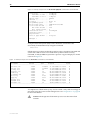
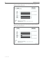
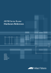
To check the amount of RAM present in a router, use the command:
show system
C613-03087-00 Rev E
38
AR700 Series Router
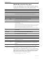
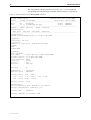
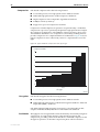
This will produce a display like that shown in Figure 12. The DRAM and
FLASH fields show the amounts of DRAM and flash memory, respectively.
Figure 12: Example output from the show system command
Router System Status
Time 10:59:39 Date 23-Mar-2006.
Board
ID Bay Board Name
Host Id Rev Serial number
-------------------------------------------------------------------------------Base
241
AT-AR750S
0 M1-0
ATR00434
PIC
38 0 AT-AR023-00 PIC Sync
0 M3-0
50200528
-------------------------------------------------------------------------------Memory DRAM : 65536 kB
FLASH : 16384 kB
Chip Revisions <U123:4567> <U23:456> <U23:5566> <U098:765>
-------------------------------------------------------------------------------SysDescription
Allied Telesis AR750S version 2.7.6-00 11-Mar-2006
SysContact
David Johns, ext 8331
SysLocation
Laboratory, First Floor, Head Office Building
SysName
LAB
SysDistName
SysUpTime
510 ( 00:00:05 )
Boot Image
:
Software Version:
Release Version :
Patch Installed :
Territory
:
Country
:
Help File
:
55_276.fbr size 732308 10-Mar-2006
2.7.6-00 11-Mar-2006
2.7.6-00 11-Mar-2006
NONE
europe
none
help.hlp
Main Fan
: On
Temperature
Main Fan Speed
: 30 Celsius
: 4500 RPM
Voltage Status ( Rail : Read )
1.2V : 1.17V
2.5V : 2.54V
5.0V : 4.84V 12.0V : 11.78V
3.3V : 2.98V
Battery voltage : 3.14V
Configuration
Boot configuration file: flash:boot.cfg (exists)
Current configuration: flash:boot.cfg
Security Mode
: Disabled
Warning (2048284): No patches found.
C613-03087-00 Rev E
Hardware Reference
39
Battery-Backed RAM (AR725, AR745, AR770S
only)
The AR725 and AR745 have 128 kB of battery-backed SRAM as NVS (nonvolatile storage), and the AR770S has 512 kB. The router can store files such as
logs and configuration scripts in NVS over a power cycle.
Onboard Flash Memory
Flash memory is a nonvolatile reprogrammable memory storage device for
router software versions, allowing upgrades to be remotely loaded from any
WAN or LAN port. Flash memory is also used to store other types of data such
as patches, logs and configurations.
There are two types of flash—onboard flash (flash connected directly to the
router’s PCB and available on all routers), and CompactFlash (flash provided
by removable compact flash cards). All the routers have onboard flash
memory; AR725 and AR745 routers also have a slot for compact flash cards.
(“CompactFlash (AR725, AR745 only)” on page 41)
Of the router’s onboard flash memory, 1 MB is reserved for the flash boot
version. You can use the rest to store files in the flash file system, such as a
software version file, GUI resource file, configuration scripts and command
line help file. The router also stores system files in the flash file system.
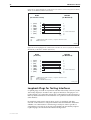
Testing Onboard Flash Memory
There are several ways to check that onboard flash memory is installed and
operating correctly. First, check that the router has recognised the flash
memory, using the command:
show system
to display system information (Figure 12 on page 38). The second part of the
display shows the types and sizes of memory installed in the router. If the flash
memory size is lower than expected, then the router’s boot process has not
correctly detected or recognised the flash memory’s presence. If recognition
fails, contact your authorised Allied Telesis distributor or reseller.
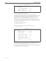
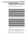
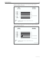
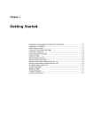
If the flash is recognised, enter the command:
show flash physical
to display flash memory size, device type and location.
C613-03087-00 Rev E
40
AR700 Series Router
Figure 13: Example output from the show flash physical command for an AT-AR750S
total size ............
available to FFS ...
available to boot ..
device type ...........
devices ...............
location ..............
programming power .....
block erase time ......
total erase blocks ....
FFS erase blocks ...
Boot erase blocks ..
erase block size ......
erase bit state .......
page buffers ..........
size of page buffer ...
16 MBytes
15 MBytes
1 MBytes
28F128
1
built in
off
1000 milliseconds
128
120
8
128 kBytes
1
1
32 bytes
Manager >
Lastly, the Flash File System (FFS) can be checked to ensure that it has
successfully formatted the flash, using the command:
show file
If flash memory has been used in the past then it may already be formatted and
contain files. With erased or new flash memory that has been correctly
formatted, an 80 byte hidden system file is present. A typical display for an FFS
is shown in Figure 14.
Figure 14: Example output from the show file command for an AT-AR750S
Filename
Device
Size
Created
Locks
------------------------------------------------------------------------55-271a.rez
flash
3796816 11 Jan-2005 13:58:28
0
55-273.rez
flash
3798416 11-Jun-2005 16:50:45
0
config.ins
flash
32
13-Dec-2004 09:37:32
0
feature.lic
flash
39
01-Dec-2004 09:45:51
0
isdn.scp
flash
1575
09-Dec-2004 15:38:50
0
longname.lfn
flash
17
23-Dec-2004 10:59:34
0
boot.cfg
flash
2769
30-Nov-2004 11:36:03
0
ppp.cfg
flash
2819
01-Dec-2004 10:14:28
0
prefer.ins
flash
64
14-Dec-2004 16:25:47
0
random.rnd
flash
3904
21-Dec-2004 12:14:24
0
release.lic
flash
32
30-Nov-2004 11:26:54
0
-------------------------------------------------------------------------
A complete test of flash memory may also be carried out by authorised support
personnel using the router’s built-in diagnostics. See “Diagnostics” on page 60
for more information.
!
C613-03087-00 Rev E
Caution The diagnostics flash memory test erases the entire flash
contents.
Hardware Reference
41
CompactFlash (AR725, AR745 only)
AR725 and AR745 routers have a CompactFlash slot on their front panel.
Compact flash cards increase the flash memory available for file storage.
CompactFlash files can be manipulated using the command line interface. Any
type of data, including versions, patches, GUIs and configurations can be
stored on compact flash cards. However, version, patch, and GUI files cannot
be run directly from CompactFlash. These files must be loaded into either NVS
or onboard Flash.
!
Caution Data contained on compact flash cards can be read with any
compliant reader. Do not keep sensitive data, for example security
keys, on compact flash cards.
The AT-CF128A 128 MB CompactFlash card has been approved for use with
the AR725 and AR745 routers. For the latest approved compact flash cards, see
the datasheet for your router at www.alliedtelesis.com . Only use approved
CompactFlash cards. Using other cards may result in data loss.
Installing and removing a compact flash card
Compact flash cards can be inserted into the CompactFlash slot at any time.
CLI messages are displayed when a card is inserted or removed. It takes
approximately two seconds for an inserted card to be initialised. Messages
notify the user when a card has been inserted:
Info (1106257): Compact flash card inserted.
and when the card is ready for use:
Info (1106268): Compact flash card initialisation successful.
A message notifies the user if the compact flash card is not compatible with the
router:
Info (3106300): Compact flash card initialisation
unsuccessful.
When CompactFlash is in use, the CompactFlash Activity LED on the front
panel of the router is green.
!
Caution Do not remove the compact flash card when it is being
written to (that is, when the CompactFlash Activity LED is lit). Doing
so will corrupt data on the file being written.
Testing CompactFlash
To display information about the basic state of a compact flash card, including
card size, file count and serial number, insert the card and enter the command:
show cflash
To display cluster ranges on a card, insert the card and enter:
show cflash test
C613-03087-00 Rev E
42
AR700 Series Router
Figure 15: Sample output from the show cflash test command, when no test is running
Clusters available for testing
Ranges:
[42645--61944]
Number of free clusters
Number of ranges
Number of used clusters
= 19300
= 1
= 42645
To test a card, insert the card and enter:
enable cflash test start=startnumber end=endnumber
where startnumber and endnumber are positive integers within a cluster range.
The endnumber must be higher than the startnumber. Cluster ranges are
displayed in the output of the show cflash test command (Figure 15).
The test software will read the file allocation table and display a list of free
sectors. Sectors can be tested as single sectors or as a range. The test will consist
of a write/read/verify cycle.
To stop the test, use the command:
disable cflash test
To display the testing process while a test is in process, enter:
show cflash test
Figure 16: Sample output from the show cflash test command, when a test is running
Test Progress
Starting cluster
Ending cluster
Current cluster
Passed clusters number
Passed sectors number
= 700
= 1700
= 1185
= 485
= 1940
Failed clusters number = 0
Failed sectors number
= 0
Used Clusters encountered = 0
Duration................
4417 ms
If used when testing is not active, the previous command displays blank
cluster ranges on a compact flash card (Figure 15 on page 42).
Error messages are displayed when a file write fails. Failure could be due to the
card being removed or an error in the card.
C613-03087-00 Rev E
Hardware Reference
43
Expansion Options
Expansion options include:
■
“AR740 RPS Redundant Power Supply (AT-AR725, AT-AR745 only)” on
page 43
■
“CompactFlash (AR725, AR745 only)” on page 41
■
“SFP Ports (AR770S only)” on page 46
■
“PICs and NSMs” on page 46
■
“PCI Accelerator Cards (PACs)” on page 47
AR740 RPS Redundant Power Supply
(AT-AR725, AT-AR745 only)
Each AR740 RPS can provide power supply and mains circuit redundancy for
up to two AC routers. The AR740 RPS cannot be used with DC versions of the
routers. Figure 17 shows the AR740 RPS front and rear panels.
Installation instructions for the AR740 RPS can be found in the AR740 RPS
Quick Install Guide. This guide is packed with each AR740 RPS, or can be
downloaded from www.alliedtelesis.com/support/software/ .
Figure 17: Front and rear panels of the AR740 RPS
Front panel
Rear panel
AC POWER 1
AC POWER 2
RPS DC OUTPUT 1
AC Power
100-240 VAC
50-60Hz
1.5A
RPS
AC Power
On
5V/6.5A
12V/1.0A
-12V/0.2A
ROUTER
RPS Fan
Fault
Main PSU
Fault
RPS PSU
Fault
RPS DC OUTPUT 2
Main Fan
Fault
5V/6.5A
12V/1.0A
-12V/0.2A
1
2
AC Power
100-240 VAC
50-60Hz
1.5A
LEDs
DC power outlets
(DB25s)
AC power
supply inlets
AC power
supply switches
DC supply cables
Two DC supply cables are packed with each AR740 RPS. If making your own
cable, use a cable that conforms to UL2464, and has at least twenty-three
24 AWG cores. The cables will need a DB25 male connector on both ends and
should be wired in a straight-through configuration. Pin outs for the
connectors are listed in Table 6.
C613-03087-00 Rev E
44
AR700 Series Router
Figure 18: DB25 male pinout on the AR740 RPS
Pin 1
Pin13
Pin 25
Pin 14
A740rpsp
Table 6: DB25 RPS power connector pin out on AR740 RPS
Specifications
Pin
Function
Direction
1, 25
Keying
-
2, 14
+12 V
output
3-5, 15-17
+5 V
output
6-8, 18-20
0V
output
9
-12 V
output
10
VCC
input
11
Main PSU error
input
12
Main fan error
input
13
0V
output
21
Sense 0 V
input
22
Sense +5 V
input
23
RPS PSU error
input
24
RPS fan error
output
Dimensions
•
Height = 44 mm (plus 5.5 mm if the rubber feet are used)
•
Width = 440 mm (excluding rack-mounting brackets)
•
Depth = 315 mm
•
Weight = 3.75 kg
Mounting System
•
1U rack mounting
Environmental Conditions
C613-03087-00 Rev E
•
Operating temperature range: 0 to 40 ºC (32 to 104 ºF)
•
Storage temperature range: -25 to 70 ºC (-13 to 158 ºF)
•
Relative humidity range: 5 to 95% non-condensing
Hardware Reference
45
LEDs
•
AC power supply
•
RPS fan fault
•
Router PSU fault
•
RPS PSU fault
•
Main (router) fan fault
AC Power Supply
•
Universal 110 VAC to 240 VAC, 50 Hz to 60 Hz input
DC Output
AR740 RPS LEDs and
what they mean
•
5 V/6.5 A
•
12 V/1.0 A
•
-12 V/0.2 A
LEDs on the rear panel indicate the RPS’s operational status.
Table 7: AR740 RPS LEDs
LED
State
Function
Power
Green
The RPS unit is receiving AC power and the
voltage is within an acceptable range.
RPS Fan Fault
Amber
The RPS is switched OFF.
Mains power to the RPS has failed.
An RPS fan has failed.
Main PSU Fault
Off
Normal operation.
Amber
The corresponding router is switched OFF or its
PSU has failed.
Mains power to the router has failed.
The DC cable between the router and RPS is
not connected.
The RPS is supplying power to the router.
RPS PSU Fault
Off
Normal operation.
Amber
The RPS is switched OFF or its PSU has failed.
Mains power to the RPS has failed.
The DC cable between the corresponding
router and RPS is not connected.
Main Fan Fault
Off
Normal operation.
Amber
The DC cable between the corresponding
router and RPS is not connected.
A main router fan has failed.
Off
Normal operation.
C613-03087-00 Rev E
46
AR700 Series Router
SFP Ports (AR770S only)
SFP (small form-factor pluggable) transceivers are compact, hot-swappable,
and high speed. Certain fibre-optic SFP transceivers are supported by the
AR770S router so that you can interchange port types to meet changing
network requirements. The AR770S router has 1000BASE-X Small Form-factor
Pluggable Eth slots conveniently located on the front panel.
Approved SFP
transceivers
SFP ports
You can purchase SFP transceivers when you purchase a router or order them
separately as needed.
These SFP transceivers are approved and supported for the AR770S router:
Product No.
Media Type
Description
AT-SPSX
(previously
AT-MG8SX)
1000BASE-SX
850 nm, 2 to 550 m with 50/125 µm MM fibre,
2 to 275 m with 62.5/125 µm MM fiber, LC
connector
AT-SPLX10
(previously
AT-MG8LX10)
1000BASE-LX
1310 nm, 2 m to 10 km with 9 µm SM fibre,
2 m to 550 m with 50 µm MM fibre, 2m to
550 m with 62.5 µm MM fibre, LC connector
AT-SPZX80
(previously
AT-MGZX)
1000BASE-ZX
1550 nm, 80 km with 9 µm SM fibre, LC
connector
For the latest list of approved SFP transceivers, contact your authorised Allied
Telesis distributor or reseller.
For instructions on inserting or removing an SFP, see the AR700 Series Router
Installation and Safety Guide packaged with your router, or available at
www.alliedtelesis.com/support/software/ .
!
Warning Do not look into SFP cables or transceivers. Invisible laser
radiation may be emitted from disconnected fibres or connectors.
PICs and NSMs
You can install PICs (Port Interface Cards) in AR700 Series routers to give the
router additional interfaces. The sections describing each router model (earlier
in this Reference) list which PICs can be installed in each model of router.
Installation information for PICs can be found in the Port Interface Card Quick
Install Guide. Detailed PIC hardware information can be found in the Port
Interface Card Hardware Reference.
NSMs can be installed in the AR745 routers. Installation information for NSMs
can be found in the Network Service Module Quick Install Guide. Detailed NSM
hardware information can be found in the Network Service Module Hardware
Reference.
The PIC and NSM Quick Install Guides and Hardware References are included
on the Documentation and Tools CD-ROM bundled with the router. They can
also be downloaded from www.alliedtelesis.com/support/software/ .
C613-03087-00 Rev E
Hardware Reference
47
PCI Accelerator Cards (PACs)
PCI Accelerator Cards (PACs) provide additional processing features or
performance, but do not add extra physical interfaces to the router. A PAC can
be installed in the dedicated PAC slot on AT-AR725 and AT-AR745 routers. The
AR750S, AR750S-DP, and AR770S routers have an inbuilt high performance
encryption processor, and therefore do not have a PAC slot.
!
Warning PACs should only be installed by authorised service
personnel. Unauthorised opening of the router’s lid may cause danger
of injury from electric shock, damage to the router, and invalidation of
the product warranty.
Two PACs are available:
How PACs work
■
AT-AR060 EPAC, Encryption PAC.
■
AT-AR061 ECPAC, Encryption/Compression PAC.
PACs provide AR725 and AR745 routers with high performance hardwarebased encryption and/or compression services. PACs have a DMA slave
processor, which operates independently of the base system. This processor is
responsible for the transfer of data between the base system and the PAC, and
the control of local high speed encryption and compression data processing
devices.
This architecture allows data encoding to be performed off-line without
involving the base router processor, thereby maximising PAC performance
while at the same time minimising impact on the router.
The PAC is a single card. Figure 19 shows the layout of the board for an
AT-AR061 ECPAC.
Figure 19: Location of main components on the AT-AR061 ECPAC card
PAC Connector
Hole for PAC fastner
Holes for PAC fasteners
PAC
C613-03087-00 Rev E
48
AR700 Series Router
Compression
PAC-based compression has the following features:
■
Local 32-bit processor for high speed control and data transfer.
■
Dedicated high performance 32-bit compression hardware.
■
High compression ratio Lempel-Ziv algorithm in hardware.
■
2 MBytes of history memory.
■
Support for up to 127 compression channels.
Compression and decompression operations are performed by a 32-bit data
compression coprocessor specifically designed for high-performance LempelZiv compression applications. The 2 MBytes of history memory allows up to
127 individual data links to use compression concurrently, enabling PACs to
provide compression for complicated network architectures. Figure 20 shows
typical compression ratios achieved by a PAC for a representative set of file
types.
Figure 20: Typical hardware compression ratios by file type
Compression Ratio
7
6
5
4
3
2
1
0
Font
Program Window
Text
Object
Spread C source
sheet
EPS
Bitmap
TIFF
File Type
CMPRATIO
Encryption
PAC-based encryption has the following features:
■
Local 32-bit processor for high speed control and data transfer.
■
Dedicated high performance 32-bit Data Encryption Standard – DES and
Triple DES (3DES) – hardware.
PAC DES and triple DES encryption are based on a fast 32-bit device that
complies with FIPS PUB 46, ISO DEA-1 and ANSI X3.92 standards.
Dual Mode
C613-03087-00 Rev E
Throughput of an encrypted link can be dramatically increased by using data
compression. To support this, ECPACs support both encryption and
compression, providing a dual mode that allows combined compression and
encryption operations. So that the compression phase will have the best
Hardware Reference
49
opportunity at finding non-random data, compression occurs before
encryption, in the order:
compression → encryption →//→ decryption → decompression
Adding compression to an encrypted link increases line throughput. Once
compression has been carried out there is less data requiring encryption,
passing back to the base system, and transferring across the network, so less
base system bus and network link bandwidth is required for a given amount of
data. This results in the dual operation being very effective where encryption is
required.
C613-03087-00 Rev E
50
AR700 Series Router
Asynchronous Interfaces
Asynchronous interfaces, also known as terminal ports, (labelled ASYN0,
ASYN1, RS-232 or CONSOLE) use RJ-45 connectors, wired as DTE with one of
two pinout wiring schemes:
■
For AR725, AR745 and AT-AR024 asynchronous port pinouts see Table 8.
■
For AR750S, AR750S-DP and AR770S asynchronous port pinouts see
Table 9.
Table 8: Pinout* of asynchronous ports for AT-AR725, AT-AR745 and AT-AR024
RJ-45 Pin
Function
Signal Direction
1
RING
Input to router (only available on expansion card interfaces)
2
DCD
Input to router
3
DTR
Output from router
4
GND
5
RXD
Input to router
6
TXD
Output from router
7
CTS
Input to router
8
RTS
Output from router
* Pins are numbered from left to right looking into the socket with the locking tab down.
Table 9: Pinout* of asynchronous interface on an AR750S, AR750S-DP,and AR770S
RJ-45 Pin
Function
Signal Direction
1
RTS
Output from router
2
DTR
Output from router
3
TXD
Output from router
4
GND
5
GND
6
RXD
Input to router
7
DCD
Input to router
8
CTS
Input to router
* Pins are numbered from left to right looking into the socket with the locking tab down.
Asynchronous interfaces follow the RS-232 standard. A range of speeds is
selectable using the set asyn command from the Interfaces chapter of the
Software Reference.
Not all signals need to be connected. In particular, DCD, DTR, CTS and RTS are
not required unless the interface has been specifically set up to use them. See
the Terminal Server chapter in the Software Reference for more details. A typical
terminal connection will only require RXD, TXD and GND, but refer to the
equipment manual for the connected device for more specific data.
LPD print ports If LPD-based printer ports are required, then the router may
expect to ‘see’ the DTR signal from the printer connected to the DCD pin of the
router. This is used to detect both the fact that the printer is ‘online’ and that it
C613-03087-00 Rev E
Hardware Reference
51
is ‘powered-on’. This prevents print jobs from being sent to a disconnected
printer and lost. See the Printer Server chapter of the Software Reference.
Cables and Loopback Plugs
This section describes how to make cables for connecting the AR router to
networks, terminals, and printers. It also describes loopback plugs, which are
required for testing most router interfaces.
RS-232 Terminal and Modem Cables
The following tables list the wiring diagrams to follow when constructing
terminal and modem cables for various connector and port combinations for
asynchronous ports.
■
For AR725, AR745 and AT-AR024 asynchronous ports see Table 10.
■
For AR750S, AR750S-DP and AR770S asynchronous ports see Table 11.
Table 10: Terminal and modem cables for AR725, AR745 and AT-AR024
Cable
Figure
Asyn port on router/PIC to DB25 female (terminal) cable (DTE to DTE) Figure 21 on page 52
Asyn port on router/PIC to DB9 female (terminal) cable (DTE to DTE) Figure 23 on page 53
Asyn port on router/PIC to DB25 male (modem) cable (DTE to DCE) Figure 25 on page 54
Asyn port on router/PIC to DB9 male (modem) cable (DTE to DCE)
Figure 27 on page 55
Asyn port on router/PIC to MiniDin (Macintosh) (DTE to DTE)
Figure 29 on page 56
Table 11: Terminal and modem cables for AR750S, AR750S-DP, and AR770S
Cable
Figure
Asyn port on router to DB25 female (terminal) cable (DTE to DTE)
Figure 22 on page 52
Asyn port on router to DB9 female (terminal) cable (DTE to DTE)
Figure 24 on page 53
Asyn port on router to DB25 male (modem) cable (DTE to DCE)
Figure 26 on page 54
Asyn port on router to DB9 male (modem) cable (DTE to DCE)
Figure 28 on page 55
Asyn port on router to MiniDin (Macintosh) (DTE to DTE)
Figure 30 on page 56
RING input The RING input is only available on asynchronous ports on
expansion cards. It is not available on asynchronous ports on base CPU boards.
An alternative method, for both terminal and modem cables, is to wire an RJ-45
patch cord (a straight pin-to-pin cable with RJ-45 connectors on both ends) and
then use an RJ-45-to-DB25 adaptor wired internally as a crossed cable. These
adaptors are available in DB9 and DB25 female and male versions from data
cabling suppliers, and are supplied with wires terminated on the RJ-45 socket
and pins on the free ends. The pins are inserted into the appropriate positions
in the DB9 or DB25 shell.
C613-03087-00 Rev E
52
AR700 Series Router
Figure 21: Pin wiring for terminal cable to connect asyn port on AR725, AR745 or
AT-AR024 to DB25 female (terminal) port
RJ45
(to switch or router)
←
→
←
→
(RXD)
(TXD)
(CTS)
(RTS)
5
6
7
8
→
←
←
←
(GND)
(DTR)
(DCD)
(RING)
4
3
2
1
Notes:
(1)
(2)
(3)
DB25 Female
(to terminal)
1 Not connected
2
3
4
5
6 Not connected
7
8
20
22
Other pins are not connected.
→ Output from switch or router; ← Input to switch or router.
Cable version 1.0.
TERMINAL
Figure 22: Pin wiring for terminal cable to connect asyn port on AR750S, AR750S-DP or
AR770S to DB25 female (terminal) port
RJ-45
(to router)
←
→
←
→
→
→
→
←
(RXD)
(TXD)
(CTS)
(RTS)
(GND)
(GND)
(DTR)
(DCD)
Notes:
(1)
(2)
(3)
6
3
8
1
4
5
2
7
DB25 Female
(to terminal)
1 Not connected
2
3
4
5
6 Not connected
7
8
20
22 Not connected
Other pins are not connected.
→ Output from switch or router; ← Input to switch or router.
Cable version 1.0.
terminal_ar750
C613-03087-00 Rev E
Hardware Reference
53
Figure 23: Pin wiring for terminal cable to connect asyn port on AR725, AR745 or
AT-AR024 to DB9 female (terminal) port
RJ-45
(to router)
→
→
←
←
→
(DTR)
(TXD)
(RXD)
(DCD)
(GND)
3
6
5
2
4
← (CTS)
→ (RTS)
← (RING)
7
8
1
Notes:
(1)
(2)
DB9 Female
(to terminal)
1
2
3
4
5
6 Not connected
7
8
9
→ Output from switch or router; ← Input to switch or router.
Cable version 1.0.
terminal_db9f
Figure 24: Pin wiring for terminal cable to connect asyn port on AR750S, AR750S-DP, or
AR770S to DB9 female (terminal) port
RJ-45
(to router)
→
→
←
←
→
→
←
→
(DTR)
(TXD)
(RXD)
(DCD)
(GND)
(GND)
(CTS)
(RTS)
Notes:
(1)
(2)
2
3
6
7
4
5
8
1
DB9 Female
(to terminal)
1
2
3
4
5
6 Not connected
7
8
9 Not connected
→ Output from switch or router; ← Input to switch or router.
Cable version 1.0.
terminal_ar750_db9f
C613-03087-00 Rev E
54
AR700 Series Router
Figure 25: Pin wiring for modem cable to connect asyn port on AR725, AR745 or
AT-AR024 to DB25 male (modem) port
RJ45
(to switch or router)
→
←
→
←
(TXD)
(RXD)
(RTS)
(CTS)
6
5
8
7
←
←
→
←
(GND)
(DCD)
(DTR)
(RING)
4
2
3
1
Notes:
(1)
(2)
(3)
DB25 Male
(to modem)
1 Not connected
2
3
4
5
6 Not connected
7
8
20
22
Other pins are not connected.
→ Output from switch or router; ← Input to switch or router.
Cable version 1.0.
MODEM
Figure 26: Pin wiring for modem cable to connect asyn port on AR750S, AR750S-DP, or
AR770S to DB25 male (modem) port
RJ-45
(to router)
→
←
→
←
→
→
←
→
(TXD)
(RXD)
(RTS)
(CTS)
(GND)
(GND)
(DCD)
(DTR)
Notes:
(1)
(2)
(3)
3
6
1
8
4
5
7
2
1
DB25 Male
(to modem)
1 Not connected
2
3
4
5
6 Not connected
7
8
20
22 Not connected
Other pins are not connected.
→ Output from switch or router; ← Input to switch or router.
Cable version 1.0.
modem_ar750
C613-03087-00 Rev E
Hardware Reference
55
Figure 27: Pin wiring for modem cable to connect asyn port on AR725, AR745 or
AT-AR024 to DB9 male (modem) port
RJ-45
(to router)
←
←
→
→
→
(DCD)
(RXD)
(TXD)
(DTR)
(GND)
2
5
6
3
4
→ (RTS)
← (CTS)
← (RING)
8
7
1
Notes:
(1)
(2)
DB9 Male
(to modem
1
2
3
4
5
6 Not connected
7
8
9
→ Output from switch or router; ← Input to switch or router.
Cable version 1.0.
modem_db9m
Figure 28: Pin wiring for modem cable to connect asyn port on AR750S, AR750S-DP, or
AR770S to DB9 male (modem) port
RJ-45
(to router)
←
←
→
→
→
→
→
←
(DCD)
(RXD)
(TXD)
(DTR)
(GND)
(GND)
(RTS)
(CTS)
Notes:
(1)
(2)
7
6
3
2
4
5
1
8
DB9 Male
(to modem)
1
2
3
4
5
6 Not connected
7
8
9 Not connected
→ Output from switch or router; ← Input to switch or router.
Cable version 1.0.
modem_ar750_db9m
C613-03087-00 Rev E
56
AR700 Series Router
Figure 29: Pin wiring diagram for a Macintosh serial cable to connect asyn port on AR725,
AR745 or AT-AR024 to MiniDin (Macintosh)
RJ45
(to switch or router)
←
→
←
→
→
←
→
(DCD)
(RTS)
(RXD)
(GND)
(TXD)
(CTS)
(DTR)
Notes:
(1)
(2)
1
2
8
5
4
6
7
3
MiniDin
(to Macintosh)
1
2
3
4
5
6 Not connected
7
8
→ Output from switch or router; ← Input to switch or router.
Cable version 1.0.
MINIDIN
Figure 30: Pin wiring diagram for a Macintosh serial cable to connect asyn port on AR750S,
AR750S-DP, or AR770S to MiniDin (Macintosh)
RJ-45
(to router)
←
←
→
←
→
→
→
→
(DCD)
(CTS)
(RTS)
(RXD)
(GND)
(TXD)
(GND)
(DTR)
Notes:
(1)
(2)
(3)
7
8
1
6
4
3
5
2
MiniDin
(to Macintosh)
1
1
2
3
4
5
6 Not connected
7
8
→ Output from switch or router; ← Input to switch or router.
Cable version 1.0.
Pin 1 on MiniDin has 2 wires.
minidin_ar750
Loopback Plugs for Testing Interfaces
Loopback plugs are used in conjunction with the Test Facility software (see the
Test Facility chapter) to test the router’s physical interfaces. The purpose of a
loopback plug is to connect the output pins on the interface to the input pins so
that any data transmitted over the interface is looped back and received at the
same interface.
On interfaces with control signals, these are also looped back. The data
received on the interface is compared with the data transmitted to determine
whether or not the interface is functioning correctly. In order to produce a
comprehensive test report, most tests performed by the Test Facility require a
loopback plug to be inserted in the interface being tested.
C613-03087-00 Rev E
Hardware Reference
57
Some interfaces (e.g., the synchronous ports) require a specially built external
testing device (available from your authorised Allied Telesis distributor or
reseller) to be used in conjunction with the Test Facility.
Table 12 lists the loopback plug wiring diagrams for each interface type.
Table 12: Loopback plug pin wiring diagrams
Physical Interface
Loopback Pin Wiring Diagram
RJ-45 asynchronous interface on AR725, AR745 or
AT-AR024
Figure 31
RJ-45 asynchronous interface on AR750S, AR750S-DP or Figure 32
AR770S
Ethernet TP interface
Figure 33
Figure 31: RJ-45 loopback plug for testing asyn interfaces AR725, AR745 or AT-AR024
8 7 6 5 4 3 2 1
(RING)
(DCD)
(DTR)
(GND)
(RXD)
(TXD)
(CTS)
(RTS)
1
2
3
4
5
6
7
8
End view
of plug
RJ45LOOP_ar7x5
Figure 32: RJ-45 loopback plug for testing asyn interfaces on AR750S, AR750S-DP, or
AR770S
8 7 6 5 4 3 2 1
(RTS)
(DTR)
(TXD)
(GND)
(GND)
(RXD)
(DCD)
(CTS)
1
2
3
4
5
6
7
8
End view
of plug
rj45loop_ar750
Figure 33: Ethernet twisted pair (TP) loopback plug
8 7 6 5 4 3 2 1
TX+
TXRX+
Not connected
Not connected
RXNot connected
Not connected
1
2
3
4
5
6
7
8
End view
of plug
TPLOOP_ar700
C613-03087-00 Rev E
58
AR700 Series Router
Test Facility
A Test Facility designed to test the router’s physical interfaces is built into all
the router software. The Test Facility can be thought of as a specialised
interface module like PPP or Frame Relay. Although the router can continue to
operate normally during specific tests, any interfaces being tested are
dedicated to the Test Facility. For more information on the Test Facility’s
operation, see the Test Facility chapter of the Software Reference.
The routers support a wide range of interface types, including Ethernet,
asynchronous, synchronous, Basic Rate ISDN and Primary Rate ISDN.
interface types (except Ethernet interfaces on the AT-AR026 PIC) can be tested
independently using the Test Facility software. Most tests, however, will also
require the use of a loopback plug. For more information on loopback plugs,
see “Loopback Plugs for Testing Interfaces” on page 56.
AR026 PIC The Test Facility does not test Ethernet interfaces on AT-AR026
PICs.
The following examples show how to test specific interfaces.
To display test results use the command:
show test
which produces a display like that shown in Figure 34.
Test failure If a test fails, please contact your authorised Allied Telesis
distributor or reseller.
Figure 34: Example output from the show test command
Board
ID Bay Board Name
Host Id Rev Serial number
---------------------------------------------------------------------------Base
241
AR750S
0 P1-0
ATR00433
PIC
38 0 AT-AR023-00 PIC Sync
0 M2-0
42199300
PIC
38 1 AT-AR023-00 PIC Sync
0 M2-0
41872128
Duration
Details
Interface State
Result
Type (minutes) Data( %OK ) Control
---------------------------------------------------------------------------eth0
no test
eth1
no test
port1
port2
port3
port4
port5
complete
complete
complete
complete
complete
syn0
syn1
no test
complete
asyn0
no test
-
-
-
-
-
-
enco0
no test
-
-
-
-
-
-
C613-03087-00 Rev E
good
good
good
good
good
good
RS-232dte
dce
X.21 dte
dce
V.35 dte
dce
2
2
2
2
2
good(100.0)
good(100.0)
good(100.0)
good(100.0)
good(100.0)
-
1
1
1
1
1
1
good(100.0)
good(100.0)
good(100.0)
good(100.0)
good(100.0)
good(100.0)
good
good
good
good
good
good
Hardware Reference
Asynchronous
Interface Tests
59
Asynchronous interfaces require a loopback plug to be installed before the test
will operate. See “Cables and Loopback Plugs” on page 51 for details of how to
make a loopback plug. To start a test of an asynchronous interface, use the
command:
enable test int=portn
where n is the interface number. This will run the test for 4 minutes. Use the
show test command (from the Test Facility chapter of the Software Reference),
to observe the test progress.
Ethernet Interface
Tests for Switch and
Eth Ports
A loopback plug is required to run the first part of the Ethernet test on eth ports
and switch ports. See “Cables and Loopback Plugs” on page 51 for details of
how to make a loopback plug.
To start a test of an Eth interface, use the command:
enable test int=ethn
where n is the Ethernet interface number.
To start a test of a switch port interface, use the command:
enable test int=portn
where n is the switch port number.
This will run the test for 4 minutes. Use the show test command (from the Test
Facility chapter of the Software Reference), to observe the test progress.
AR770S To test an eth port on the AR770S in 1000 Mbps mode, loop the port
back to the other eth port. To test a switch port in 1000 Mbps mode, loop the
port back to another switch port. In 10 Mbps or 100 Mbps mode, either loop the
port back to another port, or use a loopback plug. If two or more ports are
looped back to each other, you must test both ports at the same time. Use the
command:
enable test int=base
AR026 PIC The Test Facility does not test Ethernet interfaces on AT-AR026
PICs.
WAN Port Tests
To fully test synchronous interfaces, an external tester (available from your
authorised Allied Telesis distributor or reseller) is required. A loopback plug is
not required to test BRI interfaces.
To start a WAN interface test, use the command:
enable test int=synn
or
enable test int=brin
where n is the WAN interface number. This will run the test for 4 minutes. Use
the show test command (from the Test Facility chapter of the Software
Reference), to observe the test progress.
C613-03087-00 Rev E
60
AR700 Series Router
Restricted Maintenance Procedures
This section contains procedures that should only be performed by authorised
service personnel. Unauthorised use of procedures in this section may cause
danger of injury from electric shock, damage to the router, and invalidation of
the product warranty.
If you would like to know more about the procedures outlined in this section,
please contact your authorised Allied Telesis distributor or reseller.
Diagnostics
The router software includes a set of diagnostic programs. These programs
perform basic level checks of all system components. They do not run in
conjunction with the normal operating code, and require that the system be
totally dedicated to their use. A detailed knowledge of the way your router
hardware functions is necessary if diagnostics are to be used effectively.
!
Caution Diagnostic mode is only to be used by authorised service
personnel. Unauthorised use of diagnostic mode may cause the router
to cease functioning.
The router will not function as a router if diagnostic mode is running.
AR026 PIC The diagnostics programs do not perform checks on AT-AR026
PICs.
To enable diagnostics mode:
1.
Connect a terminal to the console port.
Connect a terminal to the console port (port 0) on the router’s rear panel,
and set the terminal communications parameters to:
2.
•
9600 bps
•
8 data bits
•
1 stop bit
•
No parity
•
Hardware flow control
Restart the router.
Restart the router, either by switching it off and on again using the power
switch on the rear panel, or by using the terminal to login and enter the
command:
restart reboot
C613-03087-00 Rev E
Hardware Reference
61
3.
Enable diagnostics mode during start-up.
During the router start-up process, at the prompt:
Force EPROM download (Y)?
press [Ctrl/D] on the terminal to enter diagnostics mode. A banner page is
displayed on the terminal (Figure 35). This can be used to check that the
terminal is correctly connected.
!
Caution Running the battery-backed RAM test, Full Flash test, or
Totally Erase Flash option will cause important system files to be
deleted. These will need to be reinstalled before the router can function
normally.
Figure 35: Diagnostics banner page.
* * * Diagnostic Mode * * *
version: 12-Jan-2005
Main Menu:
0. Restart
1. Full RAM test
2. ROM checksum test
3. LED test
4. Dump or Modify
Enter selection ==>
Figure 36: Example diagnostics banner page for the AR770S
* * * Diagnostic Mode * * *
version: Jul
8 2005 11:20:29
Main Menu:
0. Restart
1. Full RAM test
2. ROM checksum test
5. Battery backed RAM test
9. LED test
A. Dump or Modify
Enter selection ==>
To run a diagnostic program, enter the corresponding letter or number. There
are several sub-menus to cover all the different options. Table 13 lists the keys
that control the basic operation of the diagnostics.
Table 13: Basic commands for running diagnostics
Key
Function
Q
Quits any running tests and displays the banner page.
S
Prints a summary of test results so far.
Diagnostics are designed to be used with all models of the router, and therefore
some instances of particular tests will not be appropriate for some models. A
reasonable level of understanding of the system structure is needed to operate
C613-03087-00 Rev E
62
AR700 Series Router
diagnostics and interpret the results. Diagnostics only require the base CPU
board to be installed in the system.
To restore an AR725, AR745, AR750S, or AR770S router to normal operation,
perform a restart by switching its power switch (rear panel) OFF and ON. To
restore the AR750S-DP to normal operation, use the Reset button on the front
panel of the router.
For more information This manual is not intended as a guide to diagnostics.
Diagnostics are designed to be run by service personnel only. For more
information, contact your authorised Allied Telesis distributor or reseller.
Lithium Battery Replacement
The routers have a replaceable lithium battery. The battery should be replaced
when the router:
•
has been in storage for more than two years
•
has only been powered up intermittently over a two year period
•
loses its time setting
•
displays the message “ERROR: BBR Battery low”
•
loses its configuration during a power cycle
!
Caution Batteries should be replaced by authorised service personnel
only. Unauthorised opening of the router lid may cause danger of
injury from electric shock, damage to the router, and invalidation of
the product warranty.
The battery must be replaced by a 3 V lithium button cell, type CR2032
or equivalent.
Contacting Us
With locations covering all of the established markets in North America, Latin
America and Europe, Allied Telesis provides localized sales and technical
support worldwide. To find our representative nearest you, visit Allied Telesis
on the web at: http://www.alliedtelesis.com .
C613-03087-00 Rev E