1
Dell™ PowerConnect™
M6220/M6348/M8024 Switches
Configuration Guide
Model PCM6220/PCM6348/PCM8024
w w w. d e l l . c o m | s u p p o r t . d e l l . c o m
Notes, Notices, and Cautions
NOTE: A NOTE indicates important information that helps you make better use of your switch.
NOTICE: A NOTICE indicates either potential damage to hardware or loss of data and tells you how to avoid the
problem.
CAUTION: A CAUTION indicates a potential for property damage, personal injury, or death.
____________________
Information in this document is subject to change without notice.
© 2009 Dell Inc. All rights reserved.
Reproduction in any manner whatsoever without the written permission of Dell Inc. is strictly forbidden.
Trademarks used in this text: Dell, Dell OpenManage, the DELL logo, Inspiron, Dell Precision, Dimension, OptiPlex, PowerConnect,
PowerApp, PowerVault, Axim, DellNet, and Latitude are trademarks of Dell Inc.; Microsoft, Windows, and Windows Vista are either trademarks
or registered trademarks of Microsoft Corporation in the United States and/or other countries. Procomm Plus is a registered trademark of
Symantec Corporation or its affiliates in the U.S. and other countries.
Other trademarks and trade names may be used in this document to refer to either the entities claiming the marks and names or their products.
Dell Inc. disclaims any proprietary interest in trademarks and trade names other than its own.
Model PCM6220/PCM6348/PCM8024
June 2009
Rev. A00
Contents
1
About this Document .
Organization
. . . . . . . . . . . . . . . . . . . . . . . . . . . . . . . . . . . .
Additional Documentation .
2
. . . . . . . . . . . . . . . . . . . . . . . . . . .
System Configuration .
Traceroute
. . . . . . . . . . . . . . . . . . . . . . . . . .
9
10
. . . . . . . . . . . . . . . . . . . . . . . . . .
11
. . . . . . . . . . . . . . . . . . . . . . . . . . . . . . . . . . . .
11
CLI Example .
. . . . . . . . . . . . . . . . . . . . . . . . . . . . . . . .
. . . . . . . . . . . . . . . . . . . . . . . . . . . . .
13
. . . . . . . . . . . . . . . . . . . . . . . . . . . . . . .
13
13
13
. . . . . . . . . . . . . . . . . . . . . . . . . . . . . . . . .
16
Overview . . .
Considerations
CLI Examples .
Outbound Telnet
12
. . . . . . . . . . . . . . . . . . . . . . . . . . . . . . .
Configuration Scripting
Overview . .
CLI Examples
. . . . . . . . . . . . . . . . . . . . . . . . . . . . . . .
. . . . . . . . . . . . . . . . . . . . . . . . . . . . . . . .
. . . . . . . . . . . . . . . . . . . . . . . . . . . . . . . .
16
16
. . . . . . . . . . . . . . . . . . . . .
17
. . . . . . . . . . . . . . . . . . . . . . . . . . . . . . . .
. . . . . . . . . . . . . . . . . . . . . . . . . . . . . . . .
17
17
. . . . . . . . . . . . . . . . . . . . . . . . . . . . . . . . . . . . . .
19
Simple Network Time Protocol (SNTP)
Overview . .
CLI Examples
Syslog.
9
Overview . .
CLI Examples
Port Description
. . . . . . . . . . . . . . . . . . . . . . . . . . . . . . . .
19
19
. . . . . . . . . . . . . . . . . . . . . . . . . . . . . . . . .
21
. . . . . . . . . . . . . . . . . . . . . . . . . . . . . . . .
. . . . . . . . . . . . . . . . . . . . . . . . . . . . . . . .
21
. . . . . . . . . . . . . . . . . . . . . . . . . . . . . . . . . .
21
CLI Example . . . . . . . . . . . . . . . . . . . . . . . . . . . . . . . . .
22
CLI Example .
Storm Control .
10GBASE-T Plug-in Module Configuration
CLI Examples
. . . . . . . . . . . . . . . . . . .
23
. . . . . . . . . . . . . . . . . . . . . . . . . . . . . . . .
23
3
3
Switching Configuration .
Virtual LANs
. . . . . . . . . . . . . . . . . . . . . . . .
25
. . . . . . . . . . . . . . . . . . . . . . . . . . . . . . . . . . .
25
VLAN Configuration Example . . . .
CLI Examples . . . . . . . . . . . .
Web Interface . . . . . . . . . . . .
IP Subnet and MAC-Based VLANs .
CLI Examples . . . . . . . . . . . .
Protocol-Based VLANs . . . . . . .
Private Edge VLANs. . . . . . . . .
IGMP Snooping.
. . . . . . . . . . . . . . . . . . . .
26
26
29
29
29
30
31
. . . . . . . . . . . . . . . . . . . . . . . . . . . . . . . . .
32
Overview . .
CLI Examples
. . . . . . . . . . . . . . . . . . . .
. . . . . . . . . . . . . . . . . . . .
. . . . . . . . . . . . . . . . . . . .
. . . . . . . . . . . . . . . . . . . .
. . . . . . . . . . . . . . . . . . . .
. . . . . . . . . . . . . . . . . . . . . . . . . . . . . . . .
. . . . . . . . . . . . . . . . . . . . . . . . . . . . . . . .
IGMP Snooping Querier
CLI Examples
. . . . . . . . . . . . . . . . . . . .
. . . . . . . . . . . . . . . . . . . . . . . . . . . . .
33
. . . . . . . . . . . . . . . . . . . . . . . . . . . . . . . .
33
Link Aggregation/Port Channels .
. . . . . . . . . . . . . . . . . . . . . . . .
35
CLI Example . . . . . . . . . . . . . . . . . . . . . . . . . . . . . . . . .
. . . . . . . . . . . .
35
38
. . . . . . . . . . . . . . . . . . . . . . . . . . . . . . . . . .
38
Web Interface Configuration: LAGs/Port-channels
Port Mirroring
Overview . .
CLI Examples
Port Security
. . . . . . . . . . . . . . . . . . . . . . . . . . . . . . . .
38
38
. . . . . . . . . . . . . . . . . . . . . . . . . . . . . . . . . . .
39
Overview . .
Operation . .
CLI Examples
. . . . . . . . . . . . . . . . . . . . . . . . . . . . . . . .
. . . . . . . . . . . . . . . . . . . . . . . . . . . . . . . .
. . . . . . . . . . . . . . . . . . . . . . . . . . . . . . . .
. . . . . . . . . . . . . . . . . . . . . . . . . . . . . . . .
CLI Examples
. . . . . . . . . . . . . . . . . . . . . . . . .
40
40
. . . . . . . . . . . . . . . . . . . . . .
42
. . . . . . . . . . . . . . . . . . . . . . . . . . . . . . . .
. . . . . . . . . . . . . . . . . . . . . . . . . . . . . . . .
42
43
. . . . . . . . . . . . . . . . . . . . . . . . . . . . . . . . .
44
Denial of Service Attack Protection .
Overview . .
CLI Examples
DHCP Snooping
CLI Examples
Port Aggregator
39
39
39
. . . . . . . . . . . . . . . . . . . . . . . . . . . . . . . .
Link Layer Discovery Protocol .
. . . . . . . . . . . . . . . . . . . . . . . . . . . . . . . .
46
. . . . . . . . . . . . . . . . . . . . . . . . . . . . . . . . .
51
Overview . . . . . . . .
Simple Mode Operation .
4
32
32
. . . . . . . . . . . . . . . . . . . . . . . . . .
. . . . . . . . . . . . . . . . . . . . . . . . . .
51
53
CLI Examples . . . . . . . . . . . . . . . . . . .
Simple Switch Mode Supported CLI Commands .
sFlow .
. . . . . . . . . . . . .
54
59
. . . . . . . . . . . . . . . . . . . . . . . . . . . . . . . . . . . . . .
63
Overview
sFlow Agents
CLI Examples
. . . . . . . . . . . . .
. . . . . . . . . . . . . . . . . . . . . . . . . . . . . . . . . .
4
. . . . . . . . . . . . . . . . . . . . . . . . . . . . . . . .
. . . . . . . . . . . . . . . . . . . . . . . . . . . . . . . .
Routing Configuration
VLAN Routing.
. . . . . . . . . . . . . . . . . . . . . . . . . .
67
. . . . . . . . . . . . . . . . . . . . . . . . . . . . . . . . . .
67
CLI Examples . . . . . . . . . . . . . . . . . . . . .
Using the Web Interface to Configure VLAN Routing
Virtual Router Redundancy Protocol
. . . . . . . . . . .
67
70
. . . . . . . . . . . . . . . . . . . . . .
70
. . . . . . . . . . .
. . . . . . . . . . . . . . .
70
73
. . . . . . . . . . . . . . . . . . .
73
. . . . . . . . . . . . . . . . . . . . . . . . . . . . . . . .
. . . . . . . . . . . . . . . . . . . . . . . . . . . . . . . .
73
73
. . . . . . . . . . . . . . . . . . . . . . . . . . . . . . . . . . . . . . .
74
CLI Examples
Using the Web Interface to Configure VRRP .
. . . . . . . . . . . . . . . . . . . . . . . . . . . . . . . .
Proxy Address Resolution Protocol (ARP).
Overview . .
CLI Examples
OSPF
OSPF Concepts and Terms
CLI Examples . . . . . . .
Routing Information Protocol
. . . . . . . . . . . . . . . . . . . . . . . . .
74
76
. . . . . . . . . . . . . . . . . . . . . . . . . .
84
. . . . . . . . . . . . . . . . . . . . . . . . .
. . . . . . . . . . . . . . . . .
84
85
87
. . . . . . . . . . . . . . . . . . . . . . . . . . . . . . . .
87
RIP Configuration . . . . . . . . . . . . .
CLI Examples . . . . . . . . . . . . . . .
Using the Web Interface to Configure RIP
Route Preferences
. . . . . . . . . . . . . . . . .
. . . . . . . . . . . . . . . . .
Assigning Administrative Preferences to Routing Protocols.
Using Equal Cost Multipath . . . . . . . . . . . . . . . . . .
. . . . . . .
87
89
. . . . . . . . . . . . . . . . . . . . . . . . . . . . . .
90
. . . . . . . . . . . . . . . . . . . . . . . . . . . . . . . . . . . . .
92
Loopback Interfaces .
IP Helper
CLI Examples
5
63
64
65
. . . . . . .
. . . . . . . . . . . . . . . . . . . . . . . . . . . . . . . .
Device Security .
. . . . . . . . . . . . . . . . . . . . . . . . . . . . . .
802.1x Network Access Control
. . . . . . . . . . . . . . . . . . . . . . . . .
93
97
97
5
802.1x Network Access Control Examples
802.1X Authentication and VLANs .
. . . . . . . . . . . . . . . . .
. . . . . . . . . . . . . . . . . . . . . .
Authenticated and Unauthenticated VLANs
Guest VLAN . . . . . . . . . . . . . . . . .
CLI Examples . . . . . . . . . . . . . . . .
. . . . . . . . . . . . . . .
. . . . . . . . . . . . . . . . . .
103
. . . . . . . . . . . . . . . . . . . . . . . .
103
104
105
. . . . . . . . . . . . . . . . . . . . . . . . . .
106
. . . . . . . . . . . . . . . . . . . . . . .
106
107
108
108
108
110
. . . . . . . . . . . . . . . . . . . . . . . . . . . . . . . . . . . .
113
. . . . . . . . . . . . . . . . . . . . . . .
. . . . . . . . . . . . . . . . . . . . . . .
. . . . . . . . . . . . . . . . . . . . . . .
. . . . . . . . . . . . . . . . . . . . . . .
. . . . . . . . . . . . . . . . . . . . . . .
RADIUS Configuration Examples .
TACACS+
. . . . . . . . . . . . . . .
. . . . . . . . . . . . . . . . . . .
Overview . . . . . . . . . .
MAC ACLs . . . . . . . . . .
IP ACLs . . . . . . . . . . .
ACL Configuration Process .
IP ACL CLI Examples . . . .
MAC ACL CLI Examples . . .
RADIUS .
. . . . . . . . . . . . . . .
. . . . . . . . . . . . . . . . . . . . . . . .
Authentication Server Filter Assignment
Access Control Lists (ACLs)
. . . . . . . . . . . . . . . . . . . .
113
. . . . . . . . . . . . . . . . . . . . . . . . . . . . . . . . . . . .
115
TACACS+ Configuration Example .
Captive Portal
. . . . . . . . . . . . . . . . . . . .
116
. . . . . . . . . . . . . . . . . . . . . . . . . . . . . . . . .
117
Overview . . . . . . . . . . . . . . . . . . . . . .
Functional Description . . . . . . . . . . . . . . .
Captive Portal Configuration, Status and Statistics
Captive Portal Status . . . . . . . . . . . . . . . .
Captive Portal Statistics . . . . . . . . . . . . . .
CLI Examples . . . . . . . . . . . . . . . . . . . .
6
IPv6 .
. . . . . . . . . . .
117
117
118
121
122
122
. . . . . . . . . . . . . . . . . . . . . . . . . . . . . . . . . . . . .
127
Overview .
. . . . . . . . . . .
. . . . . . . . . . .
. . . . . . . . . . .
. . . . . . . . . . .
127
. . . . . . . . . . . . . . . . . . . . . . . . . . . .
127
. . . . . . . . . . . . . . . . . . . . . . . . . . . . . . .
128
. . . . . . . . . . . . . . . . . . . . . . . . . . . . . . . . . . . .
130
CLI Example .
DHCPv6 .
. . . . . . . . . . .
. . . . . . . . . . . . . . . . . . . . . . . . . . . . . . . . . . .
Interface Configuration
CLI Examples
6
100
100
101
101
802.1x MAC Authentication Bypass (MAB)
Operation in the Network .
CLI Examples . . . . . . .
98
. . . . . . . . . . . . . . . . . . . . . . . . . . . . . . .
131
7
Quality of Service
. . . . . . . . . . . . . . . . . . . . . . . . . . . .
Class of Service Queuing
. . . . . . . . . . . . . . . . . . . . . . . . . . .
Ingress Port Configuration . . . . . . . . .
Egress Port Configuration—Traffic Shaping
Queue configuration . . . . . . . . . . . .
Queue Management Type . . . . . . . . .
CLI Examples . . . . . . . . . . . . . . . .
Differentiated Services
. . . . . . . . . . . . . . .
. . . . . . . . . . . . . . . . . . . . . . . . . . . .
137
. . . . . . . . . . . . . . . . . . . . . . . . . . . . . . . . . .
143
. . . . . . . . . . . . . . . . . . . . . . . . . . . . . . . . . . .
143
IGMP Proxy .
. . . . . . . . . . . . . . . . . . . . . . . . . . . . . .
144
144
. . . . . . . . . . . . . . . . . . . . . . . . . . . . . . . . . .
144
CLI Examples
. . . . . . . . . . . . . . . . . . . . . . . . . . . . . . .
145
. . . . . . . . . . . . . . . . . . . . . . . . . . . . . . . . . . . .
146
CLI Example .
. . . . . . . . . . . . . . . . . . . . . . . . . . . . . . .
147
. . . . . . . . . . . . . . . . . . . . . . . . . . . . . . . . . . . . . .
148
PIM-SM .
PIM-DM .
9
. . . . . . . . . . . . . . . .
. . . . . . . . . . . . . . . . . . . . . . . . . . . . . . .
CLI Example .
PIM .
. . . . . . . . . . . . . . .
. . . . . . . . . . . . . . .
. . . . . . . . . . . . . . . .
IGMP Configuration
DVMRP .
. . . . . . . . . . . . . . .
. . . . . . . . . . . . . . .
138
140
Multicast
Overview .
133
133
134
134
134
134
CLI Example . . . . . . . . . . . . . . . .
DiffServ for VoIP Configuration Example .
8
133
Utility .
. . . . . . . . . . . . . . . . . . . . . . . . . . . . . . . . .
148
149
. . . . . . . . . . . . . . . . . . . . . . . . . . . . . . . . . . . .
151
Auto Config .
. . . . . . . . . . . . . . . . . . . . . . . . . . . . . . . . .
. . . . . . . . . . . . . . . . . . . . . . . . . . . . . . . . . .
Overview . . . . . . .
Functional Description
CLI Examples . . . . .
. . . . . . . . . . . . . . . . . . . . . . . . . .
. . . . . . . . . . . . . . . . . . . . . . . . . .
. . . . . . . . . . . . . . . . . . . . . . . . . .
151
151
151
157
7
8
1
About this Document
This configuration guide provides examples of how to use the following switches in a typical
network:
•
Dell™ PowerConnect™ M6220
•
Dell PowerConnect M6348
•
Dell PowerConnect M8024
It describes the advantages of specific functions the PowerConnect M6220/M6348/M8024 switches
and provides and includes information about configuring those functions using the command line
interface (CLI).
Organization
This document is organized as follows:
•
"System Configuration" on page 11 describes how to configure basic system and port settings, use
system interfaces and utilities, and create and use CLI scripts.
•
"Switching Configuration" on page 25 provides configuration scenarios for layer 2 switching,
including creating virtual local area networks (VLANs) and Internet Group Management Protocol
(IGMP) snooping interfaces, and enabling port security.
•
"Routing Configuration" on page 67 provides configuration scenarios for layer 3 features such as
VLAN routing, Open Shortest Path First (OSPF), and Routing Information Protocol (RIP).
•
"Device Security" on page 97 provides information on creating access control lists and configuring
RADIUS and TACACS+ servers.
•
"IPv6" on page 127 describes configuring and using IPv6-enabled interfaces in a mixed IPv6/IPv4
network.
•
"Quality of Service" on page 133 provides configuration scenarios for class-of-service (CoS)
queueing and differentiated services (DiffServ).
•
"Multicast" on page 143 describes how to configure IGMP, IGMP proxy, Distance Vector Multicast
Routing Protocol (DVMRP), and Protocol Independent Multicast (PIM) on the switch.
•
"Utility" on page 151 describes commands used to manage the switch.
About this Document
9
Additional Documentation
The following documentation provides additional information about PowerConnect
M6220/M6348/M8024 software:
10
•
The CLI Command Reference for your Dell PowerConnect switch describes the commands available
from the command-line interface (CLI) for managing, monitoring, and configuring the switch.
•
The User’s Guide for your Dell PowerConnect switch describes the Web GUI. Many of the scenarios
described in this document can be fully configured using the Web interface. This guide also provides
initial system setup and configuration instructions.
•
The Getting Started Guide for your Dell PowerConnect switch provides basic information to install,
configure, and operate the system.
•
Release notes for your Dell PowerConnect product detail the platform-specific functionality of the
software packages, including issues and workarounds.
About this Document
2
System Configuration
This section provides configuration scenarios for the following features:
•
"Traceroute" on page 11
•
"Configuration Scripting" on page 13
•
"Outbound Telnet" on page 16
•
"Simple Network Time Protocol (SNTP)" on page 17
•
"Syslog" on page 19
•
"Port Description" on page 21
•
"Storm Control" on page 21
•
"10GBASE-T Plug-in Module Configuration" on page 23
NOTE: For information on setting up the hardware and serial or TFTP connection, refer to the Getting Started
Guide for your system.
Traceroute
Use Traceroute to discover the routes that packets take when traveling on a hop-by-hop basis to their
destination through the network.
•
Maps network routes by sending packets with small Time-to-Live (TTL) values and watches the
ICMP time-out announcements
•
Command displays all L3 devices
•
Can be used to detect issues on the network
•
Tracks up to 30 hops
•
Default UDP port uses 33434 unless modified in the traceroute command
System Configuration
11
CLI Example
The following shows an example of using the traceroute command to determine how many hops there
are to the destination. The command output shows each IP address the packet passes through and how
long it takes to get there. In this example, the packet takes 16 hops to reach its destination.
console#traceroute ?
ip
ipv6
Enter IP Address.
Use keyword 'ipv6' if entering IPv6 Address.
console#traceroute 72.14.253.99
Traceroute to 72.14.253.99 ,30 hops max 0 byte packets:
1 10.131.10.1
2 210.210.108.193
3 192.168.81.1
4 210.214.5.161
5 210.214.5.169
6 124.7.202.2
7 210.18.7.166
8 202.144.2.193
9 202.144.113.151
10 72.14.196.97
11 216.239.43.216
12 216.239.43.209
13 216.239.43.222
14 216.239.43.221
15 209.85.250.88
16 209.85.250.105
17 209.85.250.91
18 216.239.47.237
19 216.239.46.211
--More-- or (q)uit
20 64.233.174.99
<10
<10
<10
<10
<10
10
40
30
30
40
40
60
40
100
130
130
160
290
240
ms
ms
ms
ms
ms
ms
ms
ms
ms
ms
ms
ms
ms
ms
ms
ms
ms
ms
ms
250 ms
<10
10
10
10
<10
<10
30
30
40
30
40
40
50
110
130
120
160
240
270
ms
ms
ms
ms
ms
ms
ms
ms
ms
ms
ms
ms
ms
ms
ms
ms
ms
ms
ms
240 ms
<10
<10
<10
10
10
<10
30
30
30
100
30
40
50
100
120
130
160
250
250
ms
ms
ms
ms
ms
ms
ms
ms
ms
ms
ms
ms
ms
ms
ms
ms
ms
ms
ms
250 ms
Hop Count = 20 Last TTL = 30 Test attempt = 90 Test Success = 90
12
System Configuration
Configuration Scripting
Configuration scripting allows you to generate a text-formatted script file that shows the current system
configuration. You can generate multiple scripts and upload and apply them to more than one switch.
Overview
Configuration scripting:
•
Provides scripts that can be uploaded from and downloaded to the system.
•
Provides flexibility to create command configuration scripts.
•
Can be applied to several switches.
•
Can save up to ten scripts up to a maximum size of 2 MB of memory.
•
Provides List, Delete, Apply, Upload, Download.
•
Provides script format of one CLI command per line.
NOTE: The startup-config and backup-config scripts are not bound by the 2 MB memory limit.
Considerations
When you use configuration scripting, keep the following considerations in mind:
•
The total number of scripts stored on the system is limited by NVRAM/FLASH size.
•
The application of scripts is partial if the script fails. For example, if the script executes five of ten
commands and the script fails, the script stops at five.
•
Scripts cannot be modified or deleted while being applied.
•
Validation of scripts checks for syntax errors only. It does not validate that the script will run.
CLI Examples
The following are examples of the commands used for configurations scripting.
Example #1: Viewing the Script Options
console#script ?
apply
delete
list
show
validate
Applies configuration script to the switch.
Deletes a configuration script file from the switch.
Lists all configuration script files present on the switch.
Displays the contents of configuration script.
Validate the commands of configuration script.
System Configuration
13
Example #2: Viewing and Deleting Existing Scripts
console#script list
Configuration Script Name
Size(Bytes)
-------------------------------- ----------abc.scr
360
running-config
360
startup-config
796
test.scr
360
4 configuration script(s) found.
2046 Kbytes free.
console#script delete test.scr
Are you sure you want to delete the configuration script(s)? (y/n)y
1 configuration script(s) deleted.
Example #3: Applying a Script to the Active Configuration
console#script apply abc.scr
Are you sure you want to apply the configuration script? (y/n)y
.....
....
Configuration script 'abc.scr' applied.
Example #4: Copying the Active Configuration into a Script
Use this command to capture the running configuration into a script.
console#show running-config running-config.scr
Config script created successfully.
14
System Configuration
Example #5: Uploading a Configuration Script to the TFTP Server
Use this command to upload a configuration script to the TFTP server.
console#copy script abc.scr tftp://10.27.64.141/abc.scr
Mode...........................................
Set TFTP Server IP.............................
TFTP Path......................................
TFTP Filename..................................
Data Type......................................
Source Filename................................
TFTP
10.27.64.141
./
abc.scr
Config Script
abc.scr
Management access will be blocked for the duration of the transfer
Are you sure you want to start? (y/n) y
267 bytes transferred
File transfer operation completed successfully.
Example #6: Downloading a Configuration Script to the TFTP Server
Use this command to download a configuration script from the TFTP server to the switch.
console#copy tftp://10.27.64.141/abc.scr script abc.scr
Mode...........................................
Set TFTP Server IP.............................
TFTP Path......................................
TFTP Filename..................................
Data Type......................................
Destination Filename...........................
TFTP
10.27.64.141
./
abc.scr
Config Script
abc.scr
Management access will be blocked for the duration of the transfer
Are you sure you want to start? (y/n) y
193 bytes transferred
Validating configuration script...
configure
exit
configure
logging web-session
bridge aging-time 100
exit
Configuration script validated.
File transfer operation completed successfully.
System Configuration
15
Example #7: Validating a Script
console#script validate abc.scr
ip address dhcp
username "admin" password 16d7a4fca7442dda3ad93c9a726597e4 level 15 encrypted
exit
Configuration script 'abc.scr' validated.
console#script apply abc.scr
Are you sure you want to apply the configuration script? (y/n)y
ip address dhcp
username "admin" password 16d7a4fca7442dda3ad93c9a726597e4 level 15 encrypted
exit
Configuration script 'abc.scr' applied.
Outbound Telnet
Overview
Outbound telnet:
•
Establishes an outbound telnet connection between a device and a remote host.
•
When a telnet connection is initiated, each side of the connection is assumed to originate and
terminate at a “Network Virtual Terminal” (NVT).
•
Server and user hosts do not maintain information about the characteristics of each other’s terminals
and terminal handling conventions.
•
Must use a valid IP address.
CLI Examples
The following are examples of the commands used in the outbound telnet feature.
Example #1: Connecting to Another System by Using Telnet
console#telnet 192.168.77.151
Trying 192.168.77.151...
console#
User:admin
Password:
(Remote Switch) >enable
Password:
console#show ip interface
Management Interface:
16
System Configuration
IP Address.....................................
Subnet Mask....................................
Default Gateway................................
Burned In MAC Address..........................
Network Configuration Protocol Current.........
Management VLAN ID.............................
10.27.65.89
255.255.254.0
10.27.64.1
00FF.F2A3.6688
DHCP
4086
Routing Interfaces:
Interface
----------
Netdir
Multi
IP Address
IP Mask
Bcast
CastFwd
--------------- --------------- -------- --------
Simple Network Time Protocol (SNTP)
Overview
The SNTP implementation has the following features:
•
Used for synchronizing network resources
•
Adaptation of NTP
•
Provides synchronized network timestamp
•
Can be used in broadcast or unicast mode
•
SNTP client implemented over UDP that listens on port 123
CLI Examples
The following are examples of the commands used in the SNTP feature.
Example #1: Viewing SNTP Options
(Dell Routing)(Config) #sntp ?
console(config)#sntp ?
authenticate
authentication-key
broadcast
client
server
trusted-key
unicast
Require authentication for received Network Time
Protocol (NTP) traffic from servers.
Define an authentication key for Simple Network Time
Protocol (SNTP).
Configure SNTP client broadcast parameters.
Configure the SNTP client parameters.
Configure SNTP server parameters.
Authenticate the identity of a system to which
SNTP will synchronize.
Configure SNTP client unicast parameters.
System Configuration
17
Example #2: Configuring the SNTP Server
console(config)#sntp server ?
<ipaddress/domain-name>
Enter SNTP server address or the domain name.
console(config)#sntp server 192.168.10.25 ?
key
Authentication
this peer.
Enable/Disable
Configure SNTP
Press enter to
poll
priority
<cr>
key to use when sending packets to
SNTP server polling.
server priority.
execute the command.
console(config)#sntp server 192.168.10.25
Example #3: Viewing SNTP Information
console#show sntp ?
configuration
Show the configuration of the Simple Network Time
Protocol (SNTP).
To show the status of the Simple Network Time
Protocol (SNTP).
status
console#show sntp configuration
Polling interval: 64 seconds
MD5 Authentication keys:
Authentication is not required for synchronization.
Trusted keys:
No trusted keys.
Unicast clients: Enable
Unicast servers:
Server
Key
------------------192.168.0.1
Disabled
Polling
----------Enabled
Priority
---------1
console#show sntp status
Client Mode:
Last Update Time:
Unicast
JUN 08 20:26:02 2009
Unicast servers:
Server
Status
------------------192.168.10.25 Unknown
18
System Configuration
Last response
-------------------------00:00:00 Jan 1 1970
Syslog
Overview
Syslog:
•
Allows you to store system messages and/or errors.
•
Can store to local files on the switch or a remote server running a syslog daemon.
•
Provides a method of collecting message logs from many systems.
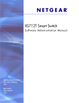
Interpreting Log Files
Figure 2-1 describes the information that displays in log messages.
Figure 2-1.
<130>
Log Files Key
JAN
01
00:00:06
A
B
A.
B.
C.
D.
E.
F.
G.
H
I.
0.0.0.0-1
UNKN [0x800023]:
C
D
E
bootos.c(386)
F
%% Event (0xaaaaaaaa)
4
G
H
I
Priority
Timestamp
Stack ID
Component Name
Thread ID
File Name
Line Number
Sequence Number
Message
CLI Examples
The following are examples of the commands used in the Syslog feature.
Example #1: Viewing Logging Information
console#show logging
Logging is enabled
Console Logging: level warning. Console Messages: 230 Dropped.
Buffer Logging: level info. Buffer Messages: 230 Logged.
File Logging: level notActive. File Messages: 0 Dropped.
CLI Command Logging : disabled
Web Session Logging : disabled
System Configuration
19
SNMP Set Command Logging : disabled
0 Messages were not logged.
Buffer Log:
<189> JAN 01 03:57:58 10.27.65.86-1 TRAPMGR[216282304]: traputil.c(908) 31 %%
Instance 0 has elected a new STP root: 8000:00ff:f2a3:8888
<189> JAN 01 03:57:58 10.27.65.86-1 TRAPMGR[216282304]: traputil.c(908) 32 %%
Instance 0 has elected a new STP root: 8000:0002:bc00:7e2c
<189> JAN 01 04:04:18 10.27.65.86-1 TRAPMGR[231781808]: traputil.c(908) 33 %% New
Spanning Tree Root: 0, Unit: 1
<189> JAN 01 04:04:18 10.27.65.86-1 TRAPMGR[216282304]: traputil.c(908) 34 %% The
unit 1 elected as the new STP root
Example #2: Viewing the Logging File
console#show logging file
Persistent Logging
Persistent Log Count
: disabled
: 0
Example #5: Configuring Syslog Server
console(config)#logging ?
buffered
cli-command
console
facility
file
on
snmp
web-session
<ip-address|hostname>
Buffered (In-Memory) Logging Configuration.
CLI Command Logging Configuration.
Console Logging Configuration.
Syslog Facility Configuration.
Configure logging file parameters.
Enable logging to all supporting destinations.
SNMP Set Command Logging Configuration.
Web Session Logging Configuration.
Configure syslog server IP address or Hostname up to
63 characters in length
console(config)#logging 192.168.10.65
console(Config-logging)#?
description
exit
level
port
Specify
To exit
Specify
Specify
syslog server description.
from the mode.
logging level.
UDP port (default is 514).
console(Config-logging)#level ?
alert
critical
debug
emergency
20
System Configuration
Immediate action needed
Critical conditions
Debugging messages
System is unusable
error
info
notice
warning
Error conditions
Informational messages
Normal but significant conditions
Warning conditions
console(Config-logging)#level critical
Port Description
The Port Description feature lets you specify an alphanumeric interface identifier that can be used for
SNMP network management.
CLI Example
Use the commands shown below for the Port Description feature.
Example #1: Enter a Description for a Port
This example specifies the name “Test” for port 1/g17:
console#configure
console(config)#interface ethernet 1/g17
console(config-if-1/g17)#description Test
console(config-if-1/g17)#exit
console(config)#exit
Example #2: Show the Port Description
console#show interfaces description ethernet 1/g17
Port Description
---- ---------------------------------------------------------1/g17 Test
Storm Control
A traffic storm occurs when incoming packets flood the LAN resulting in network performance
degradation. The Storm Control feature protects against this condition.
The switch software provides broadcast, multicast, and unicast storm recovery for individual interfaces.
Unicast Storm Control protects against traffic whose MAC addresses are not known by the system.
For broadcast, multicast, and unicast storm control, if the rate of traffic ingressing on an interface
increases beyond the configured threshold for that type, the traffic is dropped.
To configure storm control, you will enable the feature for all interfaces or for individual interfaces, and
you will set the threshold (storm control level) beyond which the broadcast, multicast, or unicast traffic
will be dropped.
System Configuration
21
Configuring a storm-control level also enables that form of storm-control. Disabling a storm-control level
(using the “no” version of the command) sets the storm-control level back to default value and disables
that form of storm-control. Using the “no” version of the “storm-control” command (not stating a
“level”) disables that form of storm-control but maintains the configured “level” (to be active next time
that form of storm-control is enabled).
NOTE: The actual rate of ingress traffic required to activate storm-control is based on the size of incoming packets
and the hard-coded average packet size of 512 bytes - used to calculate a packet-per-second (pps) rate - as the
forwarding-plane requires pps versus an absolute rate kbps. For example, if the configured limit is 10%, this is
converted to ~25000 pps, and this pps limit is set in forwarding plane (hardware). You get the approximate desired
output when 512bytes packets are used.
CLI Example
The following examples show how to configure the storm control feature an Ethernet interface. The
interface number is 1/g17.
Example #1: Set Broadcast Storm Control for an Interface
console#configure
console(config)#interface ethernet 1/g17
console(config-if-1/g17)#storm-control broadcast ?
<cr>
level
Press enter to execute the command.
Configure storm-control thresholds.
console(config-if-1/g17)#storm-control broadcast level ?
<rate>
Enter the storm-control threshold as percent of port
speed. Percent of port speed is converted to
PacketsPerSecond based on 512 byte average packet
size and applied to HW. Refer to documentation for
further details.
console(config-if-1/g17)#storm-control broadcast level 7
Example #2: Set Multicast Storm Control for an Interface
console(config-if-1/g17)#storm-control multicast level 8
Example #3: Set Unicast Storm Control for an Interface
console(config-if-1/g17)#storm-control unicast level 5
22
System Configuration
10GBASE-T Plug-in Module Configuration
NOTE: This feature is applicable to the PowerConnect M6220 and M8024 switches only.
The PowerConnect M6220 and M8024 switches provide two 10-Gigabit module slots that support plugin modules:
•
The M6220 supports CX-4, SFP+, XFP, and 10GBASE-T modules. The 10GBASE-T may only be used
on bay 2.
•
The M8024 supports CX-4, SFP+, and 10GBASE-T modules.
When using 10GBASE-T modules, you can configure the ports as follows:
•
Limit the port autonegotiation options — The switching mode for each of the 10GBASE-T module
ports is selected through autonegotiation and cannot be manually configured. However, you can
specify the switching modes advertised during autonegotiation. The software supports 1G, 10G, and
100M modes (full-duplex), which are advertised by default.
NOTE: The M6220 switch supports 1G and 10G modes only. The M8024 switch supports 100M, 1G, and 10G fullduplex modes.
•
Configure the port to enter low-power mode when no cable is connected (M8024 switch only) — In
low-power mode, most of the transmit, receive, and signal processing functions are disabled to
minimize power draw. The management interface remains operational. You can configure each of the
10GBASE-T module ports to automatically enter low-power mode when no cable is connected.
CLI Examples
Example #1: Limit the Set of Autonegotiation Options
The following example limits the switch mode options that are advertised during autonegotiation to 1G,
full-duplex.
console(config-if-1/xg17)#negotiation 1000f
Use a space to separate additional modes:
console(config-if-1/xg17)#negotiation 1000f 10000f
Example#2: Configure Low-Power Mode When No Cable is Connected (M8024 switch only)
The following example enables the port to automatically enter low-power mode when no cable is
connected:
console(config-if-1/xg17)#low-power
System Configuration
23
Use the following command to display the current status of low-power mode on an interface (see the
Admin State column):
console#show interfaces configuration
24
Port
Type
Duplex
Speed
Neg
----1/xg1
....
1/xg21
1/xg22
....
-----------------------------10G - Level
-----N/A
------Unknown
---Auto
MDIX
Mode
---Auto
10G - Level
10G - Level
Full
N/A
1000
Unknown
Auto
Auto
Auto
Auto
System Configuration
Admin
State
--------Up
Up
Low-power
3
Switching Configuration
This section provides configuration scenarios for the following features:
•
"Virtual LANs" on page 25
•
"IGMP Snooping" on page 32
•
"IGMP Snooping Querier" on page 33
•
"Link Aggregation/Port Channels" on page 35
•
"Port Mirroring" on page 38
•
"Port Security" on page 39
•
"Link Layer Discovery Protocol" on page 40
•
"Denial of Service Attack Protection" on page 42
•
"DHCP Snooping" on page 44
•
"Port Aggregator" on page 51
•
"sFlow" on page 63
Virtual LANs
Adding Virtual LAN (VLAN) support to a Layer 2 switch offers some of the benefits of both bridging
and routing. Like a bridge, a VLAN switch forwards traffic based on the Layer 2 header, which is fast.
Like a router, it partitions the network into logical segments, which provides better administration,
security and management of multicast traffic.
A VLAN is a set of end stations and the switch ports that connect them. You can have many reasons
for the logical division, for example, department or project membership. The only physical
requirement is that the end station, and the port to which it is connected, both belong to the same
VLAN.
Each VLAN in a network has an associated VLAN ID, which appears in the IEEE 802.1Q tag in the
Layer 2 header of packets transmitted on a VLAN. An end station may omit the tag, or the VLAN
portion of the tag, in which case the first switch port to receive the packet may either reject it or
insert a tag using its default VLAN ID. A given port may handle traffic for more than one VLAN, but
it can only support one default VLAN ID.
Two features let you define packet filters that the switch uses as the matching criteria to determine if
a particular packet belongs to a particular VLAN:
Switching Configuration
25
•
The IP-subnet Based VLAN feature lets you map IP addresses to VLANs by specifying a source IP
address, network mask, and the desired VLAN ID.
•
The MAC-based VLAN feature let packets originating from end stations become part of a VLAN
according to source MAC address. To configure the feature, you specify a source MAC address and a
VLAN ID.
The Private Edge VLAN feature lets you set protection between ports located on the switch. This means
that a protected port cannot forward traffic to another protected port on the same switch.
The feature does not provide protection between ports located on different switches.
For information about authenticated, unauthenticated, and guest VLANs, see "802.1X Authentication
and VLANs" on page 100.
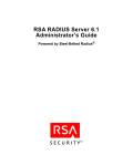
VLAN Configuration Example
The diagram in this section shows a switch with four ports configured to handle the traffic for two
VLANs. Port 1/g18 handles traffic for both VLANs, while port 1/g17 is a member of VLAN 2 only, and
ports 1/g19 and 1/g20 are members of VLAN 3 only. The script following the diagram shows the
commands you would use to configure the switch as shown in the diagram.
Figure 3-1.
VLAN Example Network Diagram
Layer 3 Switch
Port 1/g17
VLAN 2
Port 1/g18
VLANs 2 & 3
VLAN2
Port 1/g20
VLAN 3
Port 1/g19
VLAN 3
VLAN3
CLI Examples
The following examples show how to create VLANs, assign ports to the VLANs, and assign a VLAN as the
default VLAN to a port.
26
Switching Configuration
Example #1: Create Two VLANs
Use the following commands to create two VLANs and to assign the VLAN IDs while leaving the names
blank.
console(config)#vlan database
console(config-vlan)#vlan 2
console(config-vlan)#vlan 3
console(config-vlan)#exit
Example #2: Assign Ports to VLAN2
This sequence shows how to assign ports to VLAN2, specify that frames will always be transmitted
tagged from all member ports, and that untagged frames will be rejected on receipt.
console(config)#interface ethernet 1/g17
console(config-if-1/g17)#switchport mode general
console(config-if-1/g17)#switchport general allowed vlan add 2 tagged
console(config-if-1/g17)#switchport general acceptable-frame-type tagged-only
console(config-if-1/g17)#exit
console(config)#interface ethernet 1/g18
console(config-if-1/g18)#switchport mode general
console(config-if-1/g18)#switchport general allowed vlan add 2 tagged
console(config-if-1/g18)#switchport general acceptable-frame-type tagged-only
console(config-if-1/g18)#exit
Example #3: Assign Ports to VLAN3
This example shows how to assign the ports that will belong to VLAN 3. Untagged frames will be
accepted on ports 1/g19 and 1/g20.
Note that port 1/g18 belongs to both VLANs and that port 1/g17 does not belong to VLAN 3.
console(config)#interface ethernet 1/g18
cconsole(config-if-1/g18)#switchport general allowed vlan add 3
console(config-if-1/g18)#exit
console(config)#interface ethernet 1/g19
console(config-if-1/g19)#switchport general allowed vlan add 3
console(config-if-1/g19)#exit
console(config)#interface ethernet 1/g20
console(config-if-1/g20)#switchport general allowed vlan add 3
Switching Configuration
27
Example #4: Assign VLAN3 as the Default VLAN
This example shows how to assign VLAN 3 as the default VLAN for port 1/g18.
console(config)#interface ethernet 1/g18
console(config-if-1/g18)#switchport general pvid 3
Example #5: Assign IP Addresses to VLAN 2
In order for the VLAN to function as a routing interface, you must enable routing on the VLAN and on
the switch. Routing is only permitted on VLAN interfaces. Routing on physical interfaces is not
supported.
console#configure
console(config)#interface vlan 2
console(config-if-vlan2)#ip address 192.168.10.33 255.255.255.0
console(config-if-vlan2)#routing
console(config-if-vlan2)#exit
console(config)#ip routing
Example #6: View Information About VLAN 2
console#show ip interface vlan 2
Primary IP Address........................
Routing Mode..............................
Administrative Mode.......................
Forward Net Directed Broadcasts...........
Proxy ARP.................................
Local Proxy ARP...........................
Active State..............................
MAC Address...............................
Encapsulation Type........................
IP MTU....................................
Bandwidth.................................
Destination Unreachables..................
ICMP Redirects............................
28
Switching Configuration
192.168.10.33/255.255.255.0
Enable
Enable
Disable
Enable
Disable
Inactive
00FF.F2A3.888A
Ethernet
1500
10000 kbps
Enabled
Enabled
Web Interface
Use the following screens to perform the same configuration using the Web Interface:
•
Switching > VLAN > Membership. To create VLANs and specify port participation.
•
Switching > VLAN > Port Settings. To specify the PVID and mode for the port.
IP Subnet and MAC-Based VLANs
In addition to port-based VLANs, the switch also supports VLANs that are based on the IP address or
MAC address of a host. With IP subnet and MAC-based VLANs, the VLAN membership is determined
by the address of the host rather than the port to which the host is attached.
CLI Examples
The following examples show how to associate an IP subnet with a VLAN, a specific IP address with a
VLAN, and a MAC address with a VLAN.
Example #1: Associate an IP Subnet with a VLAN
This example shows how to configure the switch so that all hosts with IP addresses in the 192.168.25.0/24
network are members of VLAN 10.
console#configure
console(config)#vlan database
console(config-vlan)#vlan association subnet 192.168.25.0 255.255.255.0 10
Example #2: Associate an IP Address with a VLAN
This example shows how to configure the switch so a host with an IP addresses of 192.168.1.11 is a
member of VLAN 10.
console#configure
console(config)#vlan database
console(config-vlan)#vlan association subnet 192.168.1.11 255.255.255.255 10
Example #3: Associate a MAC Address with a VLAN
This example shows how to configure the switch so a host with a MAC address of 00:ff:f2:a3:88:86 is a
member of VLAN 10.
console#configure
console(config)#vlan database
console(config-vlan)#vlan association mac 00:ff:f2:a3:88:86 10
Switching Configuration
29
Example #4: Viewing IP Subnet and MAC-Based VLAN Associations
console#show vlan association mac
MAC Address
VLAN ID
----------------- ------00FF.F2A3.8886
10
console#show vlan association subnet
IP Subnet
IP Mask
------------------------------192.168.25.0
255.255.255.0
192.168.1.11
255.255.255.255
VLAN ID
------10
10
Protocol-Based VLANs
The software supports protocol-based VLANs, where only packets are bridged based on their layer 3
protocol. Protocol-based VLANs are most often used in situations where network segments contain hosts
running multiple protocols such as ARP, IP, and IPX. You can associate any protocol—identified by the
packet’s Ethertype field (1536 to 65535)—with a VLAN ID.
To identify a protocol with a VLAN, you first create a protocol group and assign a protocol group ID
number. You can also assign a name to the protocol group. Then, you add the protocol’s Ethertype to the
protocol group. Or, you can add a protocol to an existing protocol group.
CLI Example
The following commands create a vlan protocol group, name the group, add a protocol to it, and
associate the protocol group with a port:
console(config)#vlan protocol group 1
console(config)#vlan protocol group name 1 usergroup
console(config)#vlan protocol group add protocol 2 ethertype 0x0800
The following command associates the protocol group with a port 1/g1:
console(config)#interface ethernet 1/g1
console(config-if-1/g1)#protocol vlan group 1
To associate the protocol group with all ports, use the following command:
console(config)#protocol vlan group all 1
30
Switching Configuration
Private Edge VLANs
Use the Private Edge VLAN feature to prevent ports on the switch from forwarding traffic to each other
even if they are on the same VLAN.
•
Protected ports cannot forward traffic to other protected ports in the same group, even if they have the
same VLAN membership. Protected ports can forward traffic to unprotected ports.
•
Unprotected ports can forward traffic to both protected and unprotected ports.
You can also configure groups of protected ports, but unprotected ports are independent and cannot be
added to a group. Each group’s configuration consists of a name and a mask of ports. A port can belong
to only one set of protected ports, but an unprotected port can be added to a group as a protected port.
The group name is configurable by the network administrator.
Use the switchport protected command to designate a port as protected. Use the show
switchport protected command to display a listing of the protected ports.
CLI Example
Example #1: Configuring a Protected Port
The commands in this example name the protected port group 1 “PP_Test” and assign ports 1 and 2 to
the group.
console(config)#switchport protected 1 name PP_Test
console(config)#interface ethernet 1/g17
console(config-if-1/g17)#switchport protected 1
console(config-if-1/g17)#exit
console(config)#interface ethernet 1/g18
console(config-if-1/g18)#switchport protected 1
console(config-if-1/g18)#exit
console(config)#exit
Example #2: Viewing Protected Port Group 1
console#show switchport protected 1
Name......................................... "PP_Test"
1/g17, 1/g18
Switching Configuration
31
IGMP Snooping
This section describes the Internet Group Management Protocol (IGMP) Snooping feature. IGMP
Snooping enables the switch to monitor IGMP transactions between hosts and routers. It can help
conserve bandwidth by allowing the switch to forward IP multicast traffic only to connected hosts that
request multicast traffic.
Overview
The IGMP feature:
•
Uses Version 3 of IGMP
•
Includes snooping, which can be enabled per VLAN
CLI Examples
The following examples show commands to use with the IGMP Snooping feature.
Example #1: Enable IGMP Snooping on an Interface
First, enable IGMP Snooping on the switch:
console(config)#ip igmp snooping
Then, configure IGMP Snooping on an interface:
console(config)#interface ethernet 1/g17
console(config-if-1/g17)#ip igmp snooping?
host-time-out
leave-time-out
mrouter-time-out
<cr>
Configure host time out parameter.
Configure leave time out parameter.
Configure mrouter time out parameter.
Press enter to execute the command.
console(config-if-1/g17)#ip igmp snooping
console(config-if-1/g17)#exit
Example #2: Show IGMP Snooping Information for the Switch
console#show ip igmp snooping
Admin Mode.....................................
Multicast Control Frame Count..................
Interfaces Enabled for IGMP Snooping...........
Vlans enabled for IGMP snooping................
32
Switching Configuration
Enable
0
1/g17
None
Example #3: Show IGMP Snooping Information for an Interface
console#show ip igmp snooping interface ethernet 1/g17
Slot/Port......................................
Global IGMP Snooping Admin Mode................
IGMP Snooping Admin Mode.......................
Fast Leave Mode................................
Group Membership Interval......................
Max Response Time..............................
Multicast Router Present Expiration Time.......
1/g17
Enabled
Enabled
Disabled
260
10
300
IGMP Snooping Querier
When PIM and IGMP are enabled in a network with IP multicast routing, the IP multicast router acts as
the IGMP querier. However, if the IP-multicast traffic in a VLAN needs to be Layer 2 switched only, an
IP-multicast router is not required. The IGMP Snooping Querier can perform the IGMP snooping
functions on the VLAN.
NOTE: Without an IP-multicast router on a VLAN, you must configure another switch as the IGMP querier so that it
can send queries.
When the IGMP snooping querier is enabled, the IGMP snooping querier sends out periodic IGMP
queries that trigger IGMP report messages from the switch that wants to receive IP multicast traffic. The
IGMP snooping feature listens to these IGMP reports to establish appropriate forwarding.
CLI Examples
The following examples show commands to use with the IGMP Snooping Querier feature.
Example #1: Enable IGMP Snooping Querier on the Switch
The first command in this example enables the IGMP snooping querier on the switch. The second
command specifies the IP address that the snooping querier switch should use as the source address
when generating periodic queries.
console(config)#ip igmp snooping
console(config)#ip igmp snooping querier
console(config)#ip igmp snooping querier address 10.10.20.12
NOTE: The IGMP snooping must be enabled for the IGMP snooping querier function to operate.
Example #2: Configure IGMP Snooping Querier Properties
The first command in this example sets the IGMP Querier Query Interval time to 100. This means that
the switch waits 100 seconds before sending another general query. The second command sets the IGMP
Querier timer expiration period to 100. This means that the switch remains in Non-Querier mode for
100 seconds after it has discovered that there is a Multicast Querier in the network.
Switching Configuration
33
console(config)#ip igmp snooping querier query-interval 100
console(config)#ip igmp snooping querier timer expiry 100
Example #3: Show IGMP Snooping Querier Information
console#show ip igmp snooping querier
Global IGMP Snooping querier status
----------------------------------IGMP Snooping Querier Mode.....................
Querier Address................................
IGMP Version...................................
Querier Query Interval.........................
Querier Expiry Interval........................
Enable
10.10.10.33
2
100
100
Example #4: Enable IGMP Snooping Querier on a VLAN
To configure IGMP Snooping Querier on a VLAN, enter VLAN Database mode. The first ip igmp
snooping command in this example enables the IGMP snooping querier on VLAN 10. The second ip
igmp snooping command specifies the IP address that the snooping querier switch should use as
source address when generating periodic queries. The final command enables the Snooping Querier to
participate in the Querier Election process when it discovers the presence of another Querier in the
VLAN.
NOTE: For IGMP Snooping Querier functionality to be operationally enabled on the VLAN, IGMP Snooping and
IGMP Snooping Querier must both be enabled globally on the switch.
console(config)#vlan database
console(config-vlan)#ip igmp snooping querier 10
console(config-vlan)#ip igmp snooping querier 10 address 10.10.11.40
console(config-vlan)#ip igmp snooping querier election participate 10
34
Switching Configuration
Example #5: Show IGMP Snooping Querier Information for VLAN 10
console#show ip igmp snooping querier vlan 10
Vlan 10 :
IGMP Snooping querier status
---------------------------------------------IGMP Snooping Querier Vlan Mode................
Querier Election Participate Mode..............
Querier Vlan Address...........................
Operational State..............................
Operational version............................
Operational Max Resp Time......................
Enable
Enable
10.10.11.40
Querier
2
10
Link Aggregation/Port Channels
This section shows how to use the Link Aggregation feature to configure port-channels via the
Command Line Interface and the Graphical User Interface.
The Link Aggregation (LAG) feature allows the switch to treat multiple physical links between two endpoints as a single logical link called a port-channel. All of the physical links in a given port-channel must
operate in full-duplex mode at the same speed.
You can use the feature to directly connect two switches when the traffic between them requires high
bandwidth and reliability, or to provide a higher bandwidth connection to a public network.
You can configure the port-channels as either dynamic or static. Dynamic configuration uses the IEEE
802.3ad standard, which provides for the periodic exchanges of LACPDUs. Static configuration is used
when connecting the switch to an external switch that does not support the exchange of LACPDUs.
The feature offers the following benefits:
•
Increased reliability and availability: If one of the physical links in the port-channel goes down, traffic is
dynamically and transparently reassigned to one of the other physical links.
•
Increased bandwidth: The aggregated physical links deliver higher bandwidth than each individual
link.
•
Incremental increase in bandwidth: A physical upgrade could produce a 10-times increase in
bandwidth; LAG produces a two- or five-times increase, useful if only a small increase is needed.
Management functions treat a port-channel as if it were a single physical port.
You can include a port-channel in a VLAN. You can configure more than one port-channel for a given
switch.
CLI Example
The following shows an example of configuring the software to support Link Aggregation (LAG) to a
server and to a Layer 3 switch.
Figure 3-2 shows the example network.
Switching Configuration
35
Figure 3-2.
LAG/Port-channel Example Network Diagram
Server
Port 1/g17
Port 1/0/2
LAG_1
LAG_10
Subnet
3
Port 1/g18
Port
1/0/3
LAG_1
LAG_10
Layer 3 Switch
Port 1/g19
Port
1/0/8
LAG_2
LAG_20
Port 1/0/9
1/g20
Port
LAG_2
LAG_20
Layer 2 Switch
Subnet 2
Subnet 3
Example 1: Create Names for Two Port-Channels
console#configure
console(config)#interface port-channel 1
console(config-if-ch1)#description lag_1
console(config-if-ch1)#exit
console(config)#interface port-channel 2
console(config-if-ch2)#description lag_2
console(config-if-ch2)#exit
Example 2: Add the Physical Ports to the Port-Channels
console(config)#interface ethernet 1/g17
console(config-if-1/g17)#channel-group 1 mode auto
console(config-if-1/g17)#exit
36
Switching Configuration
console(config)#interface ethernet 1/g18
console(config-if-1/g18)#channel-group 1 mode auto
console(config-if-1/g18)#exit
console(config)#interface ethernet 1/g19
console(config-if-1/g19)#channel-group 2 mode auto
console(config-if-1/g19)#exit
console(config)#interface ethernet 1/g20
console(config-if-1/g20)#channel-group 2 mode auto
console(config-if-1/g20)#exit
console(config)#exit
Example 3: Show the Port Channels
This command shows 48 LAGs; for brevity, this example shows only 20.
console#show interfaces port-channel
Channel
------ch1
ch2
ch3
ch4
ch5
ch6
ch7
ch8
ch9
ch10
ch11
ch12
ch13
ch14
ch15
ch16
ch17
ch18
ch19
ch20
Ports
----------------------------Inactive: 1/g17, 1/g18
3
Inactive: 1/g19, 1/g20
3
No Configured Ports
No Configured Ports
No Configured Ports
No Configured Ports
No Configured Ports
No Configured Ports
No Configured Ports
No Configured Ports
No Configured Ports
No Configured Ports
No Configured Ports
No Configured Ports
No Configured Ports
No Configured Ports
No Configured Ports
No Configured Ports
No Configured Ports
No Configured Ports
Hash Algorithm Type
-------------------
3
3
3
3
3
3
3
3
3
3
3
3
3
3
3
3
3
3
At this point, the LAGs could be added to the default management VLAN.
Switching Configuration
37
Web Interface Configuration: LAGs/Port-channels
To perform the same configuration using the Graphical User Interface, click Switching > Link
Aggregation > LAG Membership in the navigation tree.
Port Mirroring
This section describes the Port Mirroring feature, which can serve as a diagnostic tool, debugging tool, or
means of fending off attacks.
Overview
Port mirroring selects network traffic from specific ports for analysis by a network analyzer, while allowing
the same traffic to be switched to its destination. You can configure many switch ports as source ports
and one switch port as a destination port. You can also configure how traffic is mirrored on a source port.
Packets received on the source port, transmitted on a port, or both received and transmitted, can be
mirrored to the destination port.
CLI Examples
The following are examples of the commands used in the Port Mirroring feature.
Example #1: Set up a Port Mirroring Session
The following command sequence enables port mirroring and specifies a source and destination ports.
console#configure
console(config)#monitor session 1 mode
console(config)#monitor session 1 source interface 1/g7 ?
rx
tx
<cr>
Monitor ingress packets only.
Monitor egress packets only.
Press enter to execute the command.
console(config)#monitor session 1 source interface 1/g7
console(config)#monitor session 1 destination interface 1/g10
console(config)#exit
Example #2: Show the Port Mirroring Session
console#show monitor session 1
Session ID
---------1
38
Admin Mode
---------Enable
Switching Configuration
Probe Port
---------1/g10
Mirrored Port
------------1/g7
Type
----Rx,Tx
Port Security
This section describes the Port Security feature.
Overview
Port Security:
•
Allows for limiting the number of MAC addresses on a given port.
•
Packets that have a matching MAC address (secure packets) are forwarded; all other packets (unsecure
packets) are restricted.
•
Enabled on a per port basis.
•
When locked, only packets with allowable MAC address will be forwarded.
•
Supports both dynamic and static.
•
Implement two traffic filtering methods. These methods can be used concurrently.
–
Dynamic Locking: User specifies the maximum number of MAC addresses that can be learned on
a port. The maximum number of MAC addresses is 100. After the limit is reached, additional
MAC addresses are not learned. Only frames with an allowable source MAC address are forwarded.
–
Static Locking: User manually specifies a list of static MAC addresses for a port.
Operation
Port Security:
•
Helps secure network by preventing unknown devices from forwarding packets.
•
When link goes down, all dynamically locked addresses are ‘freed.’
•
If a specific MAC address is to be set for a port, set the dynamic entries to 0, then only allow packets
with a MAC address matching the MAC address in the static list.
•
Dynamically locked MAC addresses are aged out if another packet with that address is not seen within
the age-out time. The user can set the time-out value.
•
Dynamically locked MAC addresses are eligible to be learned by another port.
•
Static MAC addresses are not eligible for aging.
CLI Examples
The following are examples of the commands used in the Port Security feature.
Example #1: Enable Port Security on an Interface
console(config)#interface ethernet 1/g18
console(config-if-1/g18)#port security ?
<cr>
Press enter to execute the command.
Switching Configuration
39
discard
max
Discard frames with unlearned source addresses.
Configure the maximum addresses that can be learned
on the port.
Sends SNMP Traps, and specifies the minimum time
between consecutive traps.
trap
console(config-if-1/g18)#port security
Example #2: Show Port Security
console#show ports security ?
addresses
Addresses.
ethernet
Ethernet port.
port-channel
Link Aggregation interface.
<cr>
Press enter to execute the command.
Example #3: Show Port Security on an Interface
console#show ports security ethernet 1/g18
Port
-----
Status
--------
1/g18
Locked
Action
----------------Discard
Maximum
------100
Trap
------Disable
Frequency
--------30
Link Layer Discovery Protocol
The Link Layer Discovery Protocol (LLDP) feature allows individual interfaces on the switch to advertise
major capabilities and physical descriptions. Network managers can view this information and identify
system topology and detect bad configurations on the LAN.
LLDP has separately configurable transmit and receive functions. Interfaces can transmit and receive
LLDP information.
CLI Examples
Example #1: Set Global LLDP Parameters
Use the following sequence to specify switch-wide notification interval and timers for all LLDP
interfaces.
console#configure
console(config)#lldp ?
notification-interval
timers
Configure minimum interval to send remote data
change notifications.
Configure the LLDP global timer values.
console(config)#lldp notification-interval ?
40
Switching Configuration
<interval-seconds>
Range <5 - 3600> seconds.
console(config)#lldp notification-interval 1000
console(config)#lldp timers ?
hold
interval
reinit
<cr>
The interval multiplier to set local LLDP data TTL.
The interval in seconds to transmit local LLDP data.
The delay before re-initialization.
Press enter to execute the command.
console(config)#lldp timers hold 8 reinit 5
console(config)#exit
Example #2: Set Interface LLDP Parameters
The following commands configure the Ethernet interface 1/g10 to transmit and receive LLDP
information.
console#configure
console(config)#interface ethernet 1/g10
console(config-if-1/g10)#lldp ?
notification
receive
transmit
transmit-mgmt
transmit-tlv
Enable/Disable LLDP remote data change notifications.
Enable/Disable LLDP receive capability.
Enable/Disable LLDP transmit capability.
Include/Exclude LLDP management address TLV.
Include/Exclude LLDP optional TLV(s).
console(config-if-1/g10)#lldp receive
console(config-if-1/g10)#lldp transmit
console(config-if-1/g10)#lldp transmit-mgmt
console(config-if-1/g10)#exit
console(config)#exit
Example #3: Show Global LLDP Parameters
console#show lldp
LLDP Global Configuration
Transmit Interval............................
Transmit Hold Multiplier.....................
Reinit Delay.................................
Notification Interval........................
30 seconds
8
5 seconds
1000 seconds
Switching Configuration
41
Example #4 Show Interface LLDP Parameters
console#show lldp interface 1/g10
LLDP Interface Configuration
Interface
--------1/g10
Link
-----Down
Transmit
-------Enabled
Receive
-------Enabled
Notify
-------Disabled
TLVs
-------
Mgmt
---Y
TLV Codes: 0- Port Description,
1- System Name
2- System Description, 3- System Capabilities
Denial of Service Attack Protection
This section describes the PowerConnect M6220/M6348/M8024 switches Denial of Service Protection
feature.
Overview
Denial of Service:
•
Spans two categories:
–
Protection of the switch
–
Protection of the network
•
Protects against the exploitation of a number of vulnerabilities which would make the host or network
unstable
•
Compliant with Nessus. Dell tested the switch software with Nessus version 2.0.10. Nessus is a widelyused vulnerability assessment tool.
•
PowerConnect M6220/M6348/M8024 switch software provides a number of features that help a
network administrator protect networks against DoS attacks.
There are 6 available types of attacks which can be monitored for and blocked. Each type of attack is
represented by a dos-control command keyword.
console(config)#dos-control ?
firstfrag
icmp
l4port
sipdip
tcpflag
tcpfrag
42
Switching Configuration
Enables
Enables
Enables
Enables
Enables
Enables
IPv4 first fragment checking.
ICMP size checking.
L4 port number checking.
SIP=DIP checking.
TCP flag checking.
TCP fragment checking.
The following table describes the dos-control keywords.
Table 3-1.
DoS Control
Keyword
Meaning
firstfrag
Enabling First Fragment DoS prevention causes the switch to drop packets that
have a TCP header smaller then the configured Min TCP Hdr Size.
icmp
ICMP DoS prevention causes the switch to drop ICMP packets that have a type
set to ECHO_REQ (ping) and a size greater than the configured ICMP Pkt Size.
l4port
Enabling L4 Port DoS prevention causes the switch to drop packets that have
TCP/UDP source port equal to TCP/UDP destination port.
sipdip
Enabling SIP=DIP DoS prevention causes the switch to drop packets that have a
source IP address equal to the destination IP address.
tcpflag
Enabling TCP Flag DoS prevention causes the switch to drop packets that have
TCP flag SYN set and TCP source port less than 1024 or TCP control flags set to
0 and TCP sequence number set to 0 or TCP flags FIN, URG, and PSH set and
TCP sequence number set to 0 or both TCP flags SYN and FIN set.
tcpfrag
Enabling TCP Fragment DoS prevention causes the switch to drop packets that
have an IP fragment offset equal to 1.
CLI Examples
The commands shown below show how to enable DoS protection and view its status.
Example #1: Enabling all DOS Controls
console#configure
console(config)#dos-control
console(config)#dos-control
console(config)#dos-control
console(config)#dos-control
console(config)#dos-control
console(config)#exit
sipdip
firstfrag
tcpfrag
l4port
icmp
Example #2: Viewing the DoS Configuration Information
console#show dos-control
SIPDIP Mode....................................
First Fragment Mode............................
Min TCP Hdr Size...............................
TCP Fragment Mode..............................
TCP Flag Mode..................................
L4 Port Mode...................................
ICMP Mode......................................
Max ICMP Pkt Size..............................
Enable
Enable
20
Enable
Disable
Enable
Enable
512
Switching Configuration
43
DHCP Snooping
Dynamic Host Configuration Protocol (DHCP) Snooping is a security feature that monitors DHCP
messages between a DHCP client and DHCP server to:
•
Filter harmful DHCP messages
•
Build a bindings database of (MAC address, IP address, VLAN ID, port) authorized tuples.
DHCP snooping is disabled globally and on all VLANs by default. Ports are untrusted by default.
Network administrators can enable DHCP snooping globally and on specific VLANs. They can also
configure ports within the VLAN to be trusted or untrusted. DHCP servers must be reached through
trusted ports.
DHCP snooping enforces the following security rules:
•
DHCP packets from a DHCP server (DHCPOFFER, DHCPACK, DHCPNAK,
DHCPRELEASEQUERY) are dropped if received on an untrusted port.
•
DHCPRELEASE and DHCPDECLINE messages are dropped if for a MAC addresses in the snooping
database, but the binding's interface is other than the interface where the message was received.
•
On untrusted interfaces, the switch drops DHCP packets with a source MAC address that does not
match the client hardware address. This is a configurable option.
Dynamic ARP Inspection uses the DHCP snooping bindings database to validate ARP packets.
To prevent DHCP packets being used as a DoS attack when DHCP snooping is enabled, the snooping
application enforces a rate limit for DHCP packets received on interfaces. DHCP snooping monitors the
receive rate on each interface separately. If the receive rate exceeds a configurable limit, DHCP snooping
brings down the interface. The user must do “no shutdown” on this interface to further work with that
port. The user can configure both the rate and the burst interval.
The hardware rate limits DHCP packets sent to the CPU from interfaces to 64 kbps.
The DHCP snooping application processes incoming DHCP messages. For DHCPRELEASE and
DHCPDECLINE messages, the application compares the receive interface and VLAN with the client
interface and VLAN in the bindings database. If the interfaces do not match, the application logs the
event and drops the message. For valid client messages, DHCP snooping compares the source MAC
address to the DHCP client hardware address. When there is a mismatch, DHCP snooping logs and
drops the packet. The network administrator can disable this feature using the no ip dhcp snooping
verify mac-address command. DHCP snooping forwards valid client messages on trusted members
within the VLAN. If DHCP relay co-exists with DHCP snooping, DHCP client messages are sent to
DHCP relay for further processing.
The DHCP snooping application uses DHCP messages to build and maintain the binding's database.
The binding's database only includes data for clients on untrusted ports. DHCP snooping creates a
tentative binding from DHCP DISCOVER and REQUEST messages. Tentative bindings tie a client to a
port (the port where the DHCP client message was received). Tentative bindings are completed when
DHCP snooping learns the client's IP address from a DHCP ACK message on a trusted port. DHCP
44
Switching Configuration
snooping removes bindings in response to DECLINE, RELEASE, and NACK messages. DHCP
Snooping application ignores the ACK messages as reply to the DHCP Inform messages received on
trusted ports. The administrator can also enter static bindings into the binding database.
The DHCP binding database resides on a configured external server or locally in flash depending upon
the user configuration. When a switch learns of new bindings or when it loses bindings, the switch
immediately updates the entries in the database. The switch also updates the entries in the bindings file.
The frequency at which the file is updated is based on a configurable delay, and the updates are batched.
If the absolute lease time of the snooping database entry expires, the entry is removed. If the system time
is not consistent across reboots, snooping entries will not expire properly. If a host sends a DHCP release
while the switch is rebooting, when the switch receives the DHCP discovery or request, the client's
binding will go to the tentative binding.
Figure 3-3.
DHCP Binding
No
binding
DISCOVER,
REQUEST
RELEASE,
NACK
DECLINE,
NACK
Tentative
binding
DISCOVER
Complete
binding
ACK
The DHCP snooping component does not forward server messages since they are forwarded in hardware.
DHCP snooping forwards valid DHCP client messages received on un-trusted interfaces to all trusted
interfaces within the VLAN.
The binding's database includes the following information for each entry:
•
Client MAC address
•
Client IP address
•
Time when client lease expires
•
Client VLAN ID
•
Client port
Switching Configuration
45
DHCP snooping can be configured on switching VLANs and routing VLANs. When a DHCP packet is
received on a routing VLAN, the DHCP snooping application applies its filtering rules and updates the
bindings database. If a client message passes filtering rules, the message is placed into the software
forwarding path where it may be processed by the DHCP relay agent or forwarded as an IP packet.
CLI Examples
The commands below show examples of configuring DHCP Snooping for the switch and for individual
interfaces.
Example #1 Enable DHCP snooping for the switch
console(config)#ip dhcp snooping
console(config)#exit
console#
Example #2 Enable DHCP snooping on a VLAN
console(config)#ip dhcp snooping vlan 1
console(config)#exit
console#
Example #3 Enable DHCP snooping's Source MAC verification
console(config)#ip dhcp snooping verify mac-address
console(config)#exit
Example #4 Configure DHCP snooping database remote storage parameters
console(config)#ip dhcp snooping database tftp://10.131.11.1/dsDb.txt
console(config)#
console(config)#exit
Example #5 Configure DHCP snooping database Local storage parameters
console(config)#ip dhcp snooping database local
console(config)#
console(config)#exit
Example #6 Configure DHCP snooping database Persistency interval
console(config)#ip dhcp snooping database write-delay 500
console(config)#
console(config)#exit
46
Switching Configuration
Example #7 Configure an interface as DHCP snooping trusted
console(config-if-1/g1)#ip dhcp snooping trust
console(config-if-1/g1)#exit
Example #8 Configure rate limiting on an interface
console(config-if-1/g1)#ip dhcp snooping limit rate 50 burst interval 1
console(config-if-1/g1)#exit
Example #9 Configure a DHCP snooping static binding entry
console(config)#ip dhcp snooping binding 00:01:02:03:04:05 vlan 1 10.131.11.1 interface 1/g2
console(config)#exit
Example #10 Show DHCP Snooping configuration on VLANs and Ports
show
DHCP
DHCP
DHCP
1
ip dhcp snooping binding
snooping is Enabled
snooping source MAC verification is enabled
snooping is enabled on the following VLANs:
Interface
----------1/g1
1/g2
1/g3
1/g4
1/g5
1/g6
1/g7
1/g8
1/g9
1/g10
1/g11
1/g12
1/g13
1/g14
Trusted
---------Yes
No
No
No
No
No
No
No
No
No
No
No
No
No
Log Invalid Pkts
---------------Yes
No
No
No
No
No
No
No
No
No
No
No
No
No
--More-- or (q)uit
Interface
----------1/g15
1/g16
Trusted
---------No
No
Log Invalid Pkts
---------------No
No
Switching Configuration
47
1/g17
1/g18
1/g19
1/g20
1/g21
1/g22
1/g23
1/g24
1/xg3
1/xg4
ch1
ch2
ch3
ch4
ch5
ch6
No
No
No
No
No
No
No
No
No
No
No
No
No
No
No
No
No
No
No
No
No
No
No
No
No
No
No
No
No
No
No
No
--More-- or (q)uit
console#
Example #12 Show DHCP Snooping database configurations
console#show ip dhcp snooping database
agent url: local
write-delay:
500
console#
Example #13 Show DHCP Snooping binding entries
Total number of bindings:
MAC Address
----------------00:01:02:03:04:05
00:02:B3:06:60:80
2
IP Address
--------------10.131.11.1
10.131.11.3
VLAN
---1
1
Interface
----------1/g2
1/g2
Type
------STATIC
DYNAMIC
Example #14 Show DHCP Snooping Per Port rate limiting configurations
show ip dhcp snooping interfaces
Interface
----------
48
Trust State
-------------
Switching Configuration
Rate Limit
(pps)
-------------
Burst Interval
(seconds)
---------------
Lease (Secs)
----------86400
1/g1
1/g2
1/g3
1/g4
1/g5
1/g6
1/g7
1/g8
1/g9
1/g10
1/g11
1/g12
1/g13
1/g14
1/g15
1/g16
1/g17
1/g18
Yes
No
No
No
No
No
No
No
No
No
No
No
No
No
No
No
No
No
50
15
15
15
15
15
15
15
15
15
15
15
15
15
15
15
15
15
1
1
1
1
1
1
1
1
1
1
1
1
1
1
1
1
1
1
15
15
15
15
15
15
15
15
15
15
15
15
15
15
15
15
15
15
1
1
1
1
1
1
1
1
1
1
1
1
1
1
1
1
1
1
--More-- or (q)uit
1/g19
1/g20
1/g21
1/g22
1/g23
1/g24
1/xg3
1/xg4
ch1
ch2
ch3
ch4
ch5
ch6
ch7
ch8
ch9
ch10
No
No
No
No
No
No
No
No
No
No
No
No
No
No
No
No
No
No
--More-- or (q)uit
console#
Switching Configuration
49
Example #15 Show DHCP Snooping Per Port Statistics
console#show ip dhcp snooping statistics
Interface
MAC Verify
Failures
-------------------1/g2
0
1/g3
0
1/g4
0
1/g5
0
1/g6
0
1/g7
0
1/g8
0
1/g9
0
1/g10
0
1/g11
0
1/g12
0
1/g13
0
1/g14
0
1/g15
0
1/g16
0
1/g17
0
1/g18
0
1/g19
0
1/g20
0
--More-- or (q)uit
1/g21
0
1/g22
0
1/g23
0
1/g24
0
1/xg3
0
1/xg4
0
ch1
0
ch2
0
ch3
0
ch4
0
ch5
0
ch6
0
ch7
0
ch8
0
ch9
0
ch10
0
ch11
0
ch12
0
ch13
0
ch14
0
ch15
0
50
Switching Configuration
Client Ifc
Mismatch
---------0
0
0
0
0
0
0
0
0
0
0
0
0
0
0
0
0
0
0
DHCP Server
Msgs Rec'd
----------0
0
0
0
0
0
0
0
0
0
0
0
0
0
0
0
0
0
0
0
0
0
0
0
0
0
0
0
0
0
0
0
0
0
0
0
0
0
0
0
0
0
0
0
0
0
0
0
0
0
0
0
0
0
0
0
0
0
0
0
0
ch16
ch17
--More-- or (q)uit
0
0
0
0
0
0
Port Aggregator
The Port Aggregator feature minimizes the administration required for managing the blade-centric
switch blades. This feature provides administrators the ability to map internal ports to external ports
without having to know anything about STP, VLANs, Link Aggregation or other L2/L3 protocols.
The Port Aggregator feature is only available when the switch is operating in Simple mode, which is
disabled by default. From the Dell CLI Setup Wizard, you can select the operational mode as "Simple
mode" or "Normal mode". In addition, users with privilege level 15 can change the mode via the
CLI/Web/SNMP user interfaces.
A Trap identified by "operationalModeChangeTrap" is issued when the SNMP user changes the operational mode.
Overview
Port Aggregator is simple to configure. If internal port(s) are mapped to multiple external ports for
bandwidth/high availability, these external ports will automatically be configured as an LACP trunk
group (if the Aggregator Group is configured to enable LACP automatically). All connectivity mapping is
done through a simplified user interface.
Port Aggregator is completely interoperable. Dynamic (via LACP) and static LAGs are supported.
Figure 3-4 illustrates the default condition on a standalone PowerConnect M6220 with Port Aggregator
enabled.
Switching Configuration
51
Figure 3-4.
Default Aggregator Groups on Standalone Switch (Blade)
The default Port Aggregator Group mapping is shown in Table 3-2.
Table 3-2.
Default Port Aggregator Group Mapping
Aggregator
Group
Member Internal Ports
Member Uplink (External) Ports
Group 1
1/xg1,1/xg2,1/xg3,1/xg4, 1/xg5, 1/xg6, 1/xg7,
1/xg8, 1/xg9, 1/xg10, 1/xg11, 1/xg12, 1/xg13,
1/xg14, 1/xg15, 1/xg16
1/xg17, 1/xg18, 1/xg19, 1/xg20
A standalone switch in Simple Mode supports up to 8 Aggregator Groups.
The number of internal ports in an Aggregator Group is unlimited and you can configure any number of
internal ports in each Aggregator Group. The number of external ports that can be included in a group is
limited to the maximum number of ports that can be included in a LAG. On the PowerConnect
M6220/M6348/M8024, eight ports is the maximum number that can be in a LAG. Any member port,
either internal port or external port, is not allowed to participate in more than one Aggregator Group.
52
Switching Configuration
To prevent traffic from different groups being seen by other groups, a VLAN is reserved for each
Aggregator Group by default. This VLAN reservation per group is not configurable; however you can
configure each group to participate in more than one user-created (unreserved) VLAN. VLANs 4086 to
4093 are reserved for each Aggregator Group, starting from 4086 for Group 1. The reserved VLANs are
excluded from the user-configurable VLAN list. Member ports of the Aggregator Group are excluded
from all other VLANs except the one reserved for that Group. With this reserved VLAN count, the
maximum user-configurable VLANs becomes 952 (1024-72). This VLAN segregation ensures that the
flooding occurs only within the Aggregator Group but not across. The MAC Address tables are shown for
each Aggregator Group separately and an ‘all’ option in the CLI command can be used to show all the
mac-addresses in all the groups. You are not allowed to include a VLAN in more than one aggregator
group.
To prevent network loops and maximize bandwidth to and from the switch, when the number of uplink
ports (external ports) is more than 1, you can configure the LACP (802.3ad) capability on the uplink
ports. The LAG uses hashing mode that is based on source MAC and destination MAC. You can
configure the LACP mode to static/auto/off on the multiple uplink ports. When configured in “static”
mode, the uplink ports will be set to Static mode (static LAG). When configured in “auto” mode, the
uplink ports will be put into passive state (will be able to receive LACP PDUs only) and listen for the
LACPDUs from the partner and negotiate the Link Aggregation. This means that the external (uplink)
ports will be re-enabled once LACP is detected on the active uplink without user intervention. When
configured in “off” mode, links on all but one uplink port in that Aggregator group will be forced to
DOWN. In this case, lowest numbered uplink port will be active, and all other ports will be forced to
“DOWN” state.
To support NIC teaming failover on the server blades, all the internal ports in the Aggregator Group will
be brought DOWN, if the links on all the uplink ports in that Aggregator Group are DOWN. As soon as
one or more of the uplink ports come UP, all the internal ports will be brought UP again. This is the
default behavior with respect to Link Dependency. You can also configure the minimum number of
physical uplinks ports to be active for an Aggregator Group to be active. By default this (minimum
number of uplinks ports to be active) is 1, which means if there is at least 1 external port UP in the
Aggregator Group, all the internal ports will be kept open. Internal ports in the Aggregator Group will be
downed only when all the mapped external ports are down or disconnected. For example if you configure
1/xg1, 1/xg2, 1/xg3, 1/xg4, 1/xg17, 1/xg18 as members of Group 1, and configure that the minimum
number of uplink ports to be active as ‘2’, all the internal ports of the Aggregator Group will be brought
DOWN if any one of the links on 1/xg17 or 1/xg18 is DOWN. As soon as the links on both 1/xg17 and
1/xg18 are UP, the internal ports shall be brought UP again.
Simple Mode Operation
•
A new configuration mode, Aggregator Group Mode, has been created. You can enter this mode using
the command port-aggregator group <group id> in Global Configuration mode. When Simple Mode
is enabled, negotiation, speed, duplex, vlan, and mtu configurations are allowed on the Aggregator
Group but not on the individual ports. These configuration are applied to all the member ports of the
Aggregator Group.
Switching Configuration
53
•
Operational mode is set to Normal mode on resetting the configuration to Factory defaults from the
software boot menu. The switch will boot up in this mode unless you select a different mode from the
setup wizard.
•
The switch can be changed between Normal and Simple Mode without a reboot.
•
When you change the operational mode, a trap is generated apart from logging a message.
•
The switch maintains two separate config files, one for Simple mode and another for Normal mode.
The selection of the configuration file while applying the configuration is based on the mode selection.
If there is no saved configuration, then the default configuration of the selected mode is applied.
•
Simple mode allows you to create Aggregation Groups (Figure 3-4) where internal ports and external
ports can be configured in a separate broadcast domain.
•
Security-related configurations: dot1x, RADIUS, TACACS+ are allowed when the switch is operating
in Simple Mode.
•
The switch handles traffic in the following way when in Simple Mode:
•
Ingress filtering is enabled on all ports. This means that tagged traffic would be dropped if the
incoming port is not a member of the incoming packet’s VLAN.
•
Untagged traffic should be switched and untagged at the egress.
•
Default VLAN tagged traffic should be switched and egress as untagged.
•
Tagged traffic that belongs to a user-created VLAN gets switched in that VLAN and egresses as
tagged.
The reserved VLAN ID assigned to a group is also referred to as a default VLAN.
•
The hashing algorithm in Simple mode is the same as in Normal mode. In Normal mode, the default
Hashing is based on source + destination MAC address. You cannot change the hash algorithm in
Simple mode. Ports that are already a member of a LAG are external ports that are shown using the
show port-aggregator port summary command. In Simple mode, you can set the LACP mode on a
group, but not on an individual port. Use the show interface status command to check the lag status.
CLI Examples
The following are examples of the commands used for Port Aggregator.
Example #1: Set the Operational Mode
A user with privilege level 15 can change the operational mode from Normal to Simple and vice versa.
Enter the commands to get into Global Configuration mode:
console>enable
console#configure
console(config)#
Use the mode simple command from the Global Configuration Mode to select the Simple mode as the
start up mode.
54
Switching Configuration
console(config)#mode simple
Switching modes will immediately clear the configuration.
Are you sure you want to continue? (y/n)
To select Normal mode as the operational mode, use the no form of mode simple command.
console(config)#no mode simple
Example #2: Enter Port Aggregator Mode
Use the port-aggregator group <GroupId> command to enter the Port Aggregator mode to configure
aggregator group attributes. GroupId is the Port Aggregator group identifier. (Range: 1-8) On a
standalone switch, it is up to 8. By default, all ports are in aggregator group 1.
console>enable
console#configure
console(config)#port-aggregator group 1
console(config-aggregator-1)#
Example #3: Add Member Ethernet Ports to the Aggregator Group
Use the add ethernet <intf-list> command to add member Ethernet port(s) to the Aggregator Group.
<intf-list> is a list of Ethernet interfaces.
console(config)#port-aggregator group 1
console(config-aggregator-1)#add ethernet 1/xg1
console(config-aggregator-1)#
Example #4: Set Group MTU Size on All Member Ports
Use the mtu disable command to set the mtu size to default (1518) on all the member ports in the
Aggregator Group.
console(config)#port-aggregator group 1
console(config-aggregator-1)#mtu disable
console(config-aggregator-1)#
Example #5: Set Group LACP Mode to Static
Use the lacp static command to set the LACP (Link Aggregation) mode to static for that Aggregator
Group. This means that when more than one uplink port is in the Group, those uplink ports will be
enabled automatically and will not use LACP.
console(config)#port-aggregator group 2
console(config-aggregator-2)#lacp static
console(config-aggregator-2)#
Switching Configuration
55
Example #6: Set Group LACP Mode to Dynamic
Use the lacp auto command to set the LACP (Link Aggregation) mode to dynamic for that Aggregator
Group. This means that when more than one uplink port is in the Group, those uplink ports will be
enabled automatically with LACP.
console(config)#port-aggregator group 2
console(config-aggregator-2)#lacp auto
console(config-aggregator-2)#
Example #7: Set Group LACP Mode
Use the lacp off command to set the LACP (Link Aggregation) mode to off for that Aggregator Group.
This means that when more than one uplink port is in the Group, all the uplinks are shut down except
the lowest numbered one.
console(config)#port-aggregator group 2
console(config-aggregator-2)#lacp off
console(config-aggregator-2)#
Example #8: Set Minimum Active Uplinks
Use the minimum active uplinks <number of uplinks> command to set the minimum number of
uplinks to be active for the Group. For example, if the number of uplink ports in the group is 2 and the
number of internal ports is 4. If the user sets the minimum active uplink ports to be 2, then both the
uplink ports should be active; otherwise, all the internal ports in the Group will be brought down. By
default, the minimum active uplinks for a Group is 1, which means at least one uplink port should be
active for the Aggregator Group to be active.
console(config)#port-aggregator group 2
console(config-aggregator-2)#minimum active uplinks 2
console(config-aggregator-2)#
Example #9: Show Group MAC Address Table
Use the show bridge address-table [port-aggregator group < GroupId >] command to show the MAC
address table for a particular aggregator group. [port-aggregator group <Group Id> is an optional
parameter in the command and, if not specified, shows all the MAC entries in all the Groups.
console#show bridge address-table port-aggregator group 2
Aggregator Group: 2
Aging time is 300 Sec
VLAN
MAC Address
Port
Type
-------------------------------------------3
0006.2932.814D
1/xg18
Static
1001
0006.2932.814B
1/xg17
Static
56
Switching Configuration
Example #10: Show Group VLAN Table
Use the show vlan [port-aggregator group < GroupId >] command to show the VLAN table for a
particular aggregator group. [port-aggregator group <Group Id> is an optional parameter in the
command and, if not specified, shows all the MAC entries in all the Groups.
console#show vlan port-aggregator group 2
Aggregator Group: 2
VLAN
AggregatorGroup
Type
------------------------3
2
Static
1000
2
Static
Authorization
------------Required
Required
console#show vlan
VLAN
AggregatorGroup
-------------------2
4
3
2
1000
2
1001
3
Authorization
------------Required
Required
Required
Required
Type
-----Static
Static
Static
Static
Switching Configuration
57
Example #11: Show Group Configuration Summary
Use the show port-aggregator group summary [< GroupId >] command to show the parameters
configured on the aggregator group. <Group Id> is an optional parameter in the command and, if not
specified, the command shows all the configured parameters for all the Groups.
console#show port-aggregator group summary 2
Group
----2
VLANs
----4023
Uplinks
------1
MTU
------Default
Negotiation
----------Default
console#show port-aggregator group summary
Gid
VLANs
Minimum
MTU
Negotiation
Uplinks
----------------------------1
4086
1
Disabled Default
2
4087
1
Disabled Default
3
4088
1
Disabled Default
4
4089
1
Disabled Default
Speed
-----Default
Duplex
-----Default
Speed
Duplex
------Default
Default
Default
Default
------Default
Default
Default
Default
Example #12: Show Port Summary
Use the show port-aggregator [group < GroupId >] command to show the member ports in the
aggregator group. <Group Id> is an optional parameter in the command and, if not specified, the
command shows all the Groups and member ports.
console#show port-aggregator port summary 2
Group
Member Ports
Active
Configured
Member Ports
LACP Mode
-----------------------------------2
1/xg2,1/xg6,
1/xg2,1/xg6,
static
1/xg10,1/xg14,
1/xg10,1/xg14,
1/xg18
1/xg18
Current
LACP Mode
--------auto
console#show port-aggregator port summary
Gid
Member Ports
----1
2
3
4
58
Active
Configured
Member Ports LACP Mode
--------------------------------------1/xg2-1/xg16,1/xg18-1/xg20
Dynamic
1/xg1,1/xg17,
1/xg17
Dynamic
Not configured
Dynamic
Not configured
Dynamic
Switching Configuration
Current
LACP Mode
--------Dynamic
Dynamic
Dynamic
Dynamic
Simple Switch Mode Supported CLI Commands
Commands that were available in Interface mode of Normal switch mode are now available in Simple mode
and can execute on a Port Aggregator group. For example, to apply any of the following commands on an
aggregator group 1, enter the port configuration mode for that group:
console(config)#port-aggregator group 1
console(config-aggregator-1)#
The following commands that are available in Normal switch mode are also available in Simple mode.
These are existing commands that are documented in the CLI Command Reference for your
PowerConnect switch.
•
AAA commands:
aaa authentication enable
aaa authentication login
enable authentication
enable password
ip http authentication
ip https authentication
login authentication
password (Line Configuration)
password (User EXEC)
show authentication methods
show user accounts
show users login history
username
•
Configuration and Image File Commands:
boot system
clear config
copy
delete backup-config
delete backup-image
delete startup-config
filedescr
script apply
script delete
script list
script show
script validate
show backup-config
show bootvar
show running-config
show startup-config
update bootcode
Switching Configuration
59
•
Dot1x feature commands:
aaa authentication dot1x
aaa authorization network default radius
dot1x max-req
dot1x port-control
dot1x re-authenticate
dot1x re-authentication
dot1x system-auth-control
dot1x timeout quiet-period
dot1x timeout re-authperiod
dot1x timeout server-timeout
dot1x timeout supp-timeout
dot1x timeout tx-period
show dot1x
show dot1x statistics
show dot1x users
•
Dot1x Advanced Features:
dot1x guest-vlan <vlan-id>
dot1x unauth-vlan <vlan-id>
dot1x max-users
show dot1x clients
•
Ethernet configuration commands:
clear counters [ethernet interface | port-channel port-channel-number]
show interfaces counters [ethernet interface | port-channel port-channelnumber]
show interfaces status [ethernet interface | port-channel port-channelnumber]
show statistics ethernet {<unit>/<port-type><port> | switchport}
shutdown
•
Line Commands:
exec-timeout
history
history size
line
show line
speed
•
Password Management Commands:
passwords aging
passwords history
passwords lockout
passwords min-length
show passwords configuration
60
Switching Configuration
•
Port Channel Commands:
show interfaces port-channel
show statistics port-channel
•
Radius commands:
auth-port
deadtime
key
priority
radius-server deadtime
radius-server host
radius-server key
radius-server retransmit
radius-server source-ip
radius-server timeout
retransmit
show radius-servers
source-ip
timeout
usage
•
SNMP Commands:
show snmp
show snmp engineID
show snmp groups
show snmp views
snmp-server community
snmp-server community-group
snmp-server contact
snmp-server enable traps
snmp-server engineID local
snmp-server group
snmp-server host
snmp-server location
snmp-server trap authentication
•
SSH commands:
crypto key generate dsa
crypto key generate rsa
crypto key pubkey-chain ssh
ip ssh port
ip ssh pubkey-auth
ip ssh server
key-string
show crypto key mypubkey
show crypto key pubkey-chain ssh
show ip ssh
Switching Configuration
61
user-key
•
System Management Commands:
asset-tag
hostname
member
movemanagement
ping
reload
set description
show sessions
show supported switchtype
show switch
show system
show system id
show system power
show users
show version
switch priority
switch renumber
telnet
traceroute
traceroute {ipaddress|hostname}
•
TACACS commands:
key
port
priority
show tacacs
tacacs-server host
tacacs-server key
tacacs-server timeout
timeout
•
VLAN Commands
vlan add vlan-list
vlan remove vlan-list
•
Web Server Commands:
common-name
country
crypto certificate generate
crypto certificate import
crypto certificate request
duration
ip http port
ip http server
ip https certificate
62
Switching Configuration
ip https port
ip https server
key-generate
location
organization-unit
show crypto certificate mycertificate
show ip http
show ip https
state
sFlow
This section describes the sFlow feature. sFlow is the industry standard for monitoring high-speed
switched and routed networks. sFlow technology is built into network equipment and gives complete
visibility into network activity, enabling effective management and control of network resources.
Overview
As illustrated in Figure 3-5, the sFlow monitoring system consists of sFlow Agents (embedded in a
switch, router, or standalone probe) and a central sFlow Collector. sFlow Agents use sampling technology
to capture traffic statistics from monitored devices. sFlow datagrams forward sampled traffic statistics to
the sFlow Collector for analysis.
Figure 3-5.
sFlow Architecture
sFlow Agent
sFlow Agent
sFlow Agent
sFlow Collector/Analyzer
sFlow Agent
The advantages of using sFlow are:
•
It is possible to monitor all ports of the switch continuously, with no impact on the distributed
switching performance.
•
Minimal memory/CPU is required. Samples are not aggregated into a flow-table on the switch; they are
forwarded immediately over the network to the sFlow collector.
•
System is tolerant to packet loss in the network (statistical model means loss is equivalent to slight
change in sampling rate).
Switching Configuration
63
•
sFlow collector can receive data from multiple switches, providing a real-time synchronized view of the
whole network.
•
The Collector can analyze traffic patterns based on protocols found in the headers (e.g., TCP/IP, IPX,
Ethernet, AppleTalk…). This alleviates the need for a layer 2 switch to decode and understand all
protocols.
sFlow Agents
sFlow Agents use two forms of sampling:
•
Statistical packet-based sampling of switched or routed Packet Flows
•
Time-based sampling of counters
Packet Flow Sampling and Counter Sampling are performed by sFlow Instances associated with
individual Data Sources within an sFlow Agent. Both types of samples are combined in sFlow datagrams.
Packet Flow Sampling creates a steady, but random, stream of sFlow datagrams that are sent to the sFlow
Collector. Counter samples may be taken opportunistically to fill these datagrams.
To perform Packet Flow Sampling, an sFlow Sampler Instance is configured with a Sampling Rate. Packet
Flow sampling results in the generation of Packet Flow Records. To perform Counter Sampling, an sFlow
Poller Instance is configured with a Polling Interval. Counter Sampling results in the generation of
Counter Records. sFlow Agents collect Counter Records and Packet Flow Records and send them as
sFlow datagrams to sFlow Collectors.
Packet Flow Sampling
Packet Flow Sampling, carried out by each sFlow instance, ensures that any packet observed at a Data
Source has an equal chance of being sampled, irrespective of the Packet Flow(s) to which it belongs.
Packet Flow Sampling is accomplished as follows:
1. A packet arrives on an interface.
2. The Network Device makes a filtering decision to determine whether the packet should be dropped.
3. If the packet is not filtered (dropped) a destination interface is assigned by the switching/routing
function.
4. A decision is made on whether or not to sample the packet.
The mechanism involves a counter that is decremented with each packet. When the counter reaches
zero a sample is taken.
5. When a sample is taken, the counter indicating how many packets to skip before taking the next
sample is reset. The value of the counter is set to a random integer where the sequence of random
integers used over time is the Sampling Rate.
64
Switching Configuration
Counter Sampling
The primary objective of Counter Sampling is to efficiently, periodically export counters associated with
Data Sources. A maximum Sampling Interval is assigned to each sFlow instance associated with a Data
Source.
Counter Sampling is accomplished as follows:
•
sFlow Agents keep a list of counter sources being sampled.
•
When a Packet Flow Sample is generated the sFlow Agent examines the list and adds counters to the
sample datagram, least recently sampled first. Counters are only added to the datagram if the sources
are within a short period, 5 seconds say, of failing to meet the required Sampling Interval.
•
Periodically, say every second, the sFlow Agent examines the list of counter sources and sends any
counters that must be sent to meet the sampling interval requirement.
The set of counters is a fixed set.
CLI Examples
The following are examples of the commands used for sFlow.
Example #1: Configure destination IP address and maxdatagram size for an sFlow receiver index
console(config)#sflow 1 destination 30.30.30.1 560
Example #2: Configure sFlow on an Ethernet interface range with a polling interval of 200 seconds
console(config)#sflow 1 polling ethernet 1/g1-1/g10 200
Example #3: Configure sFlow on an Ethernet interface with a polling interval of 400 seconds
console(config-if-1/g15)#sflow 1 polling 400
Example #4: Show the sFlow configuration for receiver index 1
console#show sflow 1 destination
Receiver Index.................................
Owner String...................................
Time out.......................................
IP Address:....................................
Address Type...................................
Port...........................................
Datagram Version...............................
Maximum Datagram Size..........................
1
site77
1529
30.30.30.1
1
560
5
500
Switching Configuration
65
Example #5: Show sFlow sampling for receiver index 1
console#show sflow 1 sampling
Sampler
Data Source
----------1/g1
1/g2
1/g3
1/g4
1/g5
1/g6
1/g7
1/g8
1/g9
1/g10
1/g15
Receiver
Index
------1
1
1
1
1
1
1
1
1
1
1
Packet
Sampling Rate
------------1500
1500
1500
1500
1500
1500
1500
1500
1500
1500
1500
Example #6: Show sFlow polling for receiver index 1
console#show sflow 1 polling
Poller
Data Source
----------1/g1
1/g2
1/g3
1/g4
1/g5
1/g6
1/g7
1/g8
1/g9
1/g10
1/g15
66
Receiver
Index
------1
1
1
1
1
1
1
1
1
1
1
Switching Configuration
Poller
Interval
------200
200
200
200
200
200
200
200
200
200
400
Max Header
Size
---------50
50
50
50
50
50
50
50
50
50
50
4
Routing Configuration
This section describes configuration scenarios and instructions for the following routing features:
•
"VLAN Routing" on page 67
•
"Virtual Router Redundancy Protocol" on page 70
•
"Proxy Address Resolution Protocol (ARP)" on page 73
•
"OSPF" on page 74
•
"Routing Information Protocol" on page 84
•
"Route Preferences" on page 87
•
"Loopback Interfaces" on page 90
•
"IP Helper" on page 92
VLAN Routing
This section provides an example of how to configure PowerConnect M6220/M6348/M8024 switch
software to support VLAN routing.
NOTE: The management VLAN cannot be configured as a routing interface. The switch may also be managed
via VLAN routing interfaces.
CLI Examples
The diagram in this section shows a Layer 3 switch configured for VLAN routing. It connects two
VLANs, with two ports participating in one VLAN, and one port in the other. The script shows the
commands you would use to configure PowerConnect M6220/M6348/M8024 switch software to
provide the VLAN routing support shown in the diagram.
Routing Configuration
67
Figure 4-1.
VLAN Routing Example Network Diagram
Layer 3 Switch
Physical Port 1/xg2
VLAN 10: 192.150.3.1
Physical Port 1/xg3
VLAN 10: 192.150.4.1
Physical
Port 1/xg1
Layer 2 Switch
Layer 2 Switch
VLAN 10
VLAN 20
Example 1: Create Two VLANs
The following code sequence shows an example of creating two VLANs with egress frame tagging
enabled.
console#configure
console(config)#vlan database
console(config-vlan)#vlan 10
console(config-vlan)#vlan 20
console(config-vlan)#exit
Example 2: Configure the VLAN Members
The following code sequence shows an example of adding ports to the VLANs and assigning the PVID
for each port. The PVID determines the VLAN ID assigned to untagged frames received on the ports.
console#configure
console(config)#interface ethernet
console(config-if-1/g1)#switchport
console(config-if-1/g1)#switchport
console(config-if-1/g1)#switchport
console(config-if-1/g1)#exit
console#configure
console(config)#interface ethernet
console(config-if-1/g2)#switchport
console(config-if-1/g2)#switchport
console(config-if-1/g2)#switchport
68
Routing Configuration
1/g1
mode general
general allowed vlan add 10
general pvid 10
1/g2
mode general
general allowed vlan add 10
general pvid 10
console(config-if-1/g2)#exit
console#configure
console(config)#interface ethernet
console(config-if-1/g3)#switchport
console(config-if-1/g3)#switchport
console(config-if-1/g3)#switchport
console(config-if-1/g3)#exit
1/g3
mode general
general allowed vlan add 20
general pvid 20
Example 3: Set Up VLAN Routing for the VLANs and Assign an IP Address
The following code sequence shows how to enable routing for the VLANs and how to configure the IP
addresses and subnet masks for the virtual router ports.:
console#configure
console(config)#interface vlan 10
console(config-if-vlan10)#routing
console(config-if-vlan10)#ip address 192.150.3.1 255.255.255.0
console(config-if-vlan10)#exit
console#configure
console(config)#interface vlan 20
console(config-if-vlan20)#routing
console(config-if-vlan20)#ip address 192.150.4.1 255.255.255.0
console(config-if-vlan20)#exit
Example 4: Enable Routing for the Switch:
In order for the VLAN to function as a routing interface, you must enable routing on the VLAN and on the
switch.
console(config)#ip routing
Routing Configuration
69
Using the Web Interface to Configure VLAN Routing
Use the following screens to perform the same configuration using the Web Interface:
•
Switching > VLAN > VLAN Membership. To create the VLANs and specify port participation.
•
Switching > VLAN > Port Settings. To set the PVID and VLAN type.
•
Routing > VLAN Routing > Configuration. To enable routing on Vlans.
•
Routing > IP > Configuration. To enable routing for the switch.
•
Routing > IP > Interface Configuration. To configure VLAN IP addresses and subnet masks.
Virtual Router Redundancy Protocol
When an end station is statically configured with the address of the router that will handle its routed
traffic, a single point of failure is introduced into the network. If the router goes down, the end station is
unable to communicate. Since static configuration is a convenient way to assign router addresses, Virtual
Router Redundancy Protocol (VRRP) was developed to provide a backup mechanism.
VRRP eliminates the single point of failure associated with static default routes by enabling a backup
router to take over from a “master” router without affecting the end stations using the route. The end
stations will use a “virtual” IP address that will be recognized by the backup router if the master router
fails. Participating routers use an election protocol to determine which router is the master router at any
given time. A given port may appear as more than one virtual router to the network, also, more than one
port on a switch may be configured as a virtual router. Either a physical port or a routed VLAN may
participate.
CLI Examples
This example shows how to configure the switch to support VRRP. Router 1 will be the default master
router for the virtual route, and Router 2 will be the backup router.
70
Routing Configuration
Figure 4-2.
VRRP Example Network Configuration
Layer 3 Switch acting
as Router 2
Layer 3 Switch acting
as Router 1
VLAN
60
Port
1/0/4
192.150.4.1
Virtual Router ID 20
Virtual Addr. 192.150.2.1
VLAN
50
Port 1/0/2
192.150.2.1
Virtual Router ID 20
Virtual Addr. 192.150.2.1
Layer 2 Switch
Hosts
Example 1: Configuring VRRP on the Switch as a Master Router
Enable routing for the switch. IP forwarding is then enabled by default.
console#config
console(config)#ip routing
Configure the IP addresses and subnet masks for the VLAN routing interfaces that will participate in the
protocol, for example:
console(config)#interface vlan 50
console(config-if-vlan50)#routing
console(config-if-vlan50)#ip address 192.150.2.1 255.255.255.0
console(config-if-vlan50)#exit
Enable VRRP for the switch:
console#config
console(config)#ip vrrp
Routing Configuration
71
Assign virtual router IDs to the port that will participate in the protocol:
console(config)#interface vlan 50
console(config-if-vlan50)#ip vrrp 20
Specify the IP address that the virtual router function will recognize. The priority default is 255.
console(config-if-vlan50)#ip vrrp 20 ip 192.150.2.1
Enable VRRP on the port:
console(config-if-vlan50)#ip vrrp 20 mode
console(config-if-vlan50)#exit
Example 2: Configuring VRRP on the Switch as a Backup Router
Enable routing for the switch. IP forwarding is then enabled by default.
console#config
console(config)#ip routing
Configure the IP addresses and subnet masks for the port that will participate in the protocol:
console(config)#interface vlan 60
console(config-if-vlan60)#routing
console(config-if-vlan60)#ip address 192.150.4.1 255.255.255.0
console(config-if-vlan60)#exit
Enable VRRP for the switch:
console#config
console(config)#ip vrrp
Assign virtual router IDs to the port that will participate in the protocol:
console(config)#interface vlan 60
console(config-if-vlan60)#ip vrrp 20
Specify the IP address that the virtual router function will recognize.
console(config-if-vlan60)#ip vrrp 20 ip 192.150.2.1
Set the priority for the port. The default priority is 100.
console(config-if-vlan60)#ip vrrp 20 priority 254
72
Routing Configuration
Enable VRRP on the port.
console(config-if-vlan60)#ip vrrp 20 mode
console(config-if-vlan60)#exit
Using the Web Interface to Configure VRRP
Use the following screens to perform the same configuration using the Graphical User Interface:
•
Routing > IP > Configuration. To enable routing for the switch.
•
Routing > IP > Interface Configuration. To enable routing for the VLAN interfaces and configure
their IP addresses and subnet masks.
•
Routing > VRRP > VRRP Configuration. To enable VRRP for the switch
•
Routing > VRRP > Virtual Router Configuration. To configure the interface for VRRP.
Proxy Address Resolution Protocol (ARP)
This section describes the Proxy Address Resolution Protocol (ARP) feature.
Overview
•
Proxy ARP allows a router to answer ARP requests where the target IP address is not the router itself
but a destination that the router can reach.
•
If a host does not know the default gateway, proxy ARP can learn the first hop.
•
Machines in one physical network appear to be part of another logical network.
•
Without proxy ARP, a router responds to an ARP request only if the target IP address is an address
configured on the interface where the ARP request arrived.
CLI Examples
The following are examples of the commands used in the proxy ARP feature.
Example #1: Enabling Proxy ARP
To enable IP Proxy ARP:
console#config
console(config)#interface vlan 10
console(config-if-vlan10)#routing
console(config-if-vlan10)#ip proxy-arp
console(config-if-vlan10)#exit
Example #2 Viewing the Interface Information
console#show ip interface vlan 50
Routing Configuration
73
Primary IP Address.............................
Routing Mode...................................
Administrative Mode............................
Forward Net Directed Broadcasts................
Proxy ARP......................................
Local Proxy ARP................................
Active State...................................
Link Speed Data Rate...........................
MAC Address....................................
Encapsulation Type.............................
IP MTU.........................................
192.150.2.1/255.255.255.0
Enable
Enable
Disable
Enable
Disable
Inactive
10 Half
00FF.F2A3.888A
Ethernet
1500
OSPF
Larger networks typically use the Open Shortest Path First (OSPF) protocol instead of RIP. To the
administrator of a large and/or complex network, OSPF offers several benefits:
•
•
Less network traffic:
–
Routing table updates are sent only when a change has occurred.
–
Only the part of the table that has changed is sent.
–
Updates are sent to a multicast, not a broadcast address.
Hierarchical management: allows the network to be subdivided.
The switch supports OSPFv2, which is used on IPv4 networks and OSPFv3, which has enhancements for
handling 128-bit IPv6 addresses. The protocols are configured separately within the software, but their
functionality is largely similar for IPv4 and IPv6 networks. The following description applies to both
protocols, except where noted.
OSPF Concepts and Terms
Figure 4-3, Figure 4-4, and Figure 4-5 show example OSPF topologies that illustrate the concepts
described in this section.
Areas and Topology
The top level of the hierarchy of an OSPF network is known as an autonomous system (AS) or routing
domain, and is a collection of networks with a common administration and routing strategy. The AS is
divided into areas. Routers within an area must share detailed information on the topology of their area,
but require less detailed information about the topology of other areas. Segregating a network into areas
enables limiting the amount of route information communicated throughout the network.
Areas are identified by a numeric ID in IP address format n.n.n.n (note, however, that these are not used
as actual IP addresses). For simplicity, the area can be configured and referred to in normal integer
notation; however, the software converts these to dot notation by using the right-most octet up to 255
and proceeding to the next left octet for higher values (i.e., Area 20 is identified as 0.0.0.20 and Area 256
74
Routing Configuration
as 0.0.1.0). The area identified as 0.0.0.0 is referred to as Area 0 and is considered the OSPF backbone.
All other OSPF areas in the network must connect to Area 0 directly or through a virtual link. The
backbone area is responsible for distributing routing information between non-backbone areas.
A virtual link can be used to connect an area to Area 0 when a direct link is not possible. A virtual link
traverses an area between the remote area and Area 0 (see Figure 4-5).
A stub area is an area that does not receive routes that were learned from a protocol other than OSPF or
were statically configured. These routes typically send traffic outside the AS. Therefore, routes from a
stub area to locations outside the AS use the default gateway. A virtual link cannot be configured across a
stub area. A Not So Stubby Area can import limited external routes only from a connected ASBR.
OSPF Routers and LSAs
OSPF routers keep track of the state of the various links they send data to. Routers share OSPF link state
advertisements (LSAs) with other routers. Various LSA types provide detailed information on a link for
sharing within an area or summary information for sharing outside an area. External LSAs provide
information on static routes or routes learned from other routing protocols.
OSPF defines various router types:
•
Backbone routers have an interface in Area 0. They condense and summarize information about all the
areas in the AS and advertise this information on the backbone.
•
Area border routers (ABRs) connect areas to the OSPF backbone (in the case of virtual links, the an
ABR may connect to another ABR that provides a direct connection to Area 0). An ABR is a member of
each area it connects to.
•
Internal routers (IRs) route traffic within an area. When two routers in an area discover each other
through OSPF Hello messages, they are called OSPF neighbors. Neighbors share detailed information
on the topology of the area using local LSAs.
•
Autonomous system boundary routers (ASBRs) connect to other ASes. ASBRs use other protocols such
as BGP or RIP to communicate outside the AS. The ASBR performs route redistribution; i.e., when it
learns routes from other protocols, it originates external LSAs that advertise those prefixes within the
AS.
Metrics and Route Selection
You can configure the metric type of external routes originated through route redistribution. The metric
type influences the routes computed by other OSPF routers in the domain.
OSPF determines the best route using the assigned cost and the type of the OSPF route. The following
order is used for choosing a route if more than one type of route exists:
1 Intra-area (the source and destination address are in the same area)
2 Inter-area (the source and destination are not in the same area, i.e., the route crosses the OSPF
backbone)
3 External Type 1
4 External Type 2
Routing Configuration
75
External routes are those imported into OSPF from other routing protocol or processes. OSPF computes
the path cost differently for external type 1 and external type 2 routes. The cost of an external type 1
route is the cost advertised in the external LSA plus the path cost from the calculating router to the
ASBR. The cost of an external type 2 route is the cost advertised by the ASBR in its external LSA.
NOTE: The following example uses the CLI to configure OSPF. You can also use the Web interface. Click Routing >
OSPF or IPv6 > OSPFv3 in the navigation tree.
CLI Examples
Example 1: Configuring an OSPF Border Router and Setting Interface Costs
The following example shows you how to configure an OSPF border router areas and interfaces in the
switch.
Figure 4-3.
OSPF Example Network Diagram: Border Router
VLAN 50
192.150.2.1
VLAN 70
192.150.2.2
VLAN 80
192.150.3.1
IPv4 (OSPFv2)
•
IPv6 (OSPFv3)
Enable routing for the switch:
console#config
ip routing
exit
76
VLAN 90
192.150.4.1
Routing Configuration
console#config
ipv6 unicast-routing
exit
IPv4 (OSPFv2)
IPv6 (OSPFv3)
Enable routing and assign IP for VLANs 70, 80 and 90.
config
interface vlan 70
routing
ip address 192.150.2.2 255.255.255.0
exit
config
interface vlan 70
routing
ipv6 enable
interface vlan 80
routing
ip address 192.130.3.1 255.255.255.0
exit
exit
interface vlan 80
routing
ipv6 address 2002::1/64
exit
interface vlan 90
routing
ip address 192.64.4.1 255.255.255.0
exit
interface vlan 90
routing
ipv6 address 2003::1/64
exit
exit
exit
Specify a router ID. Disable 1583 compatibility to prevent a routing loop (IPv4-only).
config
router ospf
router-id 192.150.9.9
no 1583compatibility
exit
config
ipv6 router ospf
router-id 1.1.1.1
exit
exit
exit
OSPF is globally enabled by default. To make it operational on the router, you configure OSPF for particular
interfaces and identify which area the interface is associated with. The following commands also sets the
priority and cost for the ports:
Routing Configuration
77
IPv4 (OSPFv2)
IPv6 (OSPFv3)
config
config
interface vlan 70
ip ospf area 0.0.0.0
ip ospf priority 128
ip ospf cost 32
exit
interface vlan 80
ip ospf area 0.0.0.2
ip ospf priority 255
ip ospf cost 64
exit
interface vlan 90
ip ospf area 0.0.0.2
ip ospf priority 255
ip ospf cost 64
exit
exit
interface vlan 70
ipv6 ospf
ipv6 ospf areaid 0.0.0.0
ipv6 ospf priority 128
ipv6 ospf cost 32
exit
interface vlan 80
ipv6 ospf
ipv6 ospf areaid 0.0.0.2
ipv6 ospf priority 255
ipv6 ospf cost 64
exit
interface vlan 90
ipv6 ospf
ipv6 ospf areaid 0.0.0.2
ipv6 ospf priority 255
ipv6 ospf cost 64
exit
exit
Example 2: Configuring Stub and NSSA Areas
In this example, Area 0 connects directly to two other areas: Area 1 is defined as a stub area and Area 2 is
defined as an NSSA area.
NOTE: OSPFv2 and OSPFv3 can operate concurrently on a network and on the same interfaces (although they do
not interact). This example configures both protocols simultaneously.
Figure 4-4 illustrates this example OSPF configuration.
78
Routing Configuration
Figure 4-4.
OSPF Configuration—Stub Area and NSSA Area
Area 2 (0.0.0.2)
IR (5.3.0.0)
10.1.101.1
3000:1:101::/64
Area 0 (0.0.0.0)
Router 1 (1.1.1.1)
10.1.2.1
3000:1:2::/64
10.1.2.2
3000:2:3::
10.1.2.2
3000:1:2::
10.3.100.3
Backbone Router (3.3.3.3) 3000:3:100::
ASBR (5.1.0.0)
10.2.3.3
3000:2:3::
Router 2 (2.2.2.2)
10.2.3.3
3000:2:3::
Virtual Link
10.2.4.2
3000:2:4::
Area 1 (0.0.0.1) - stub
IR (5.4.0.0)
Area 4 (0.0.0.4) - NSSA
Configure Router A: Router A is a backbone router. It links to an ASBR (not defined here) that routes
traffic outside the AS.
•
Globally enable IPv6 and IPv4 routing:
(console) #configure
ipv6 unicast-routing
ip routing
•
Configure IP address and enable OSPF on VLAN routing interfaces 6 and 12 and enable IPv6 OSPF on
the interfaces. (OSPF is enabled on the IPv4 interface in the next code group.)
interface vlan 6
routing
ip address 10.2.3.3 255.255.255.0
ipv6 address 3000:2:3::/64 eui64
ip ospf area 0.0.0.0
ipv6 ospf
exit
interface vlan 12
routing
ip address 10.3.100.3
255.255.255.0
Routing Configuration
79
ipv6 address 3000:3:100::/64 eui64
ip ospf area 0.0.0.0
ipv6 ospf
exit
•
Define an OSPF router:
ipv6 router ospf
router-id 3.3.3.3
exit
router ospf
router-id 3.3.3.3
exit
exit
Configure Router B: Router B is a ABR that connects Area 0 to Areas 1 and 2.
•
Configure IPv6 and IPv4 routing. The static routes are included for illustration only: Redistributed
static routes, like routes distributed from other protocols, are not injected into stub areas such as Area
1:
(console)#configure
ipv6 unicast-routing
ipv6 route 3000:44:44::/64 3000:2:3::210:18ff:fe82:c14
ip route 10.23.67.0 255.255.255.0 10.2.3.3
•
On VLANs 10, 5, and 17, configure IPv4 and IPv6 addresses and enable OSPF. For IPv6, associate
VLAN 10 with Area 1 and VLAN 17 with Area 2. (OSPF is enabled on the IPv4 VLAN routing interface
in the next code group.)
interface vlan 10
routing
ip address 10.1.2.2 255.255.255.0
ipv6 address 3000:1:2::/64 eui64
ipv6 ospf
ipv6 ospf areaid 1
exit
interface vlan 5
routing
ip address 10.2.3.2 255.255.255.0
ipv6 address 3000:2:3::/64 eui64
ipv6 ospf
exit
interface vlan 17
routing
ip address 10.2.4.2 255.255.255.0
80
Routing Configuration
ipv6 address 3000:2:4::/64 eui64
ipv6 ospf
ipv6 ospf areaid 2
exit
•
For IPv4: Define an OSPF router. Define Area 1 as a stub. Enable OSPF for IPv4 on VLANs 10, 5, and
17 by globally defining the range of IP addresses associated with each interface, and then associating
those ranges with Areas 1, 0, and 17, respectively. Then, configure a metric cost to associate with static
routes when they are redistributed via OSPF:
router ospf
router-id 2.2.2.2
area 0.0.0.1 stub
area 0.0.0.2 nssa
network 10.1.2.0 0.0.0.255
network 10.2.3.0 0.0.0.255
network 10.2.4.0 0.0.0.255
redistribute static metric
exit
•
area 0.0.0.1
area 0.0.0.0
area 0.0.0.2
1 subnets
For IPv6: Define an OSPF router. Define Area 1 as a stub and area 2 as a Not-So-Stubby-Area (NSSA).
Configure a metric cost to associate with static routes when they are redistributed via OSPF:
ipv6 router ospf
router-id 2.2.2.2
area 0.0.0.1 stub
area 0.0.0.2 nssa
redistribute static metric 105 metric-type 1
exit
exit
Example 3: Configuring a Virtual Link
In this example, Area 0 connects directly to Area 1. A virtual link is defined that traverses Area 1 and
connects to Area 2.
Figure 4-5 illustrates this example OSPF configuration.
Routing Configuration
81
Figure 4-5.
OSPF Configuration—Virtual Link
Area 2 (0.0.0.2)
IR (5.3.0.0)
10.1.101.1
VLAN 11 3000:1:101::/64
Router C - ABR (5.5.5.5)
Area 0 (0.0.0.0) - backbone
VLAN 10
10.1.2.1/24
3000:1:2::/64
VLAN 5
VLAN 7
10.1.2.2/24
3000:1:2::/64 eui64
Router B - ABR (4.4.4.4)
Virtual Link
10.2.3.3/24
3000:2:3::/64
Router A - backbone
(3.3.3.3)
10.2.3.2
3000:2:3::/64
VLAN 2
Area 1 (0.0.0.1)
Configure Router A: Router A is a backbone router. Configuration steps are similar to those for Router A
in the previous example.
(console)#configure
ipv6 unicast-routing
ip routing
exit
ipv6 router ospf
router-id 3.3.3.3
exit
interface vlan 5
routing
ip address 10.2.3.3 255.255.255.0
ipv6 address 3000:2:3::/64 eui64
ipv6 ospf
exit
router ospf
router-id 3.3.3.3
network 10.2.3.0 0.0.0.255 area 0.0.0.0
exit
exit
82
Routing Configuration
Configure Router B: Router B is a ABR that directly connects Area 0 to Area 1. In addition to the
configuration steps described in the previous example, we define a virtual link that traverses Area 1 to
Router C (5.5.5.5).
(console)#configure
ipv6 unicast-routing
ip routing
interface vlan 2
routing
ip address 10.2.3.2 255.255.255.0
ipv6 address 3000:2:3::/64 eui64
ipv6 ospf
exit
interface vlan 7
routing
ip address 10.1.2.2 255.255.255.0
ipv6 address 3000:1:2::211:88FF:FE2A:3CB3/64 eui64
ipv6 ospf
ipv6 ospf areaid 1
exit
router ospf
router-id 4.4.4.4
area 0.0.0.1 virtual-link 5.5.5.5
network 10.2.3.0 0.0.0.255 area 0.0.0.0
network 10.1.2.0 0.0.0.255 area 0.0.0.1
exit
ipv6 router ospf
router-id 4.4.4.4
area 0.0.0.1 virtual-link 5.5.5.5
exit
exit
Configure Router C: Router C is a ABR that enables a virtual link from the remote Area 2 in the AS to
Area 0. In addition to the configuration steps described for Router C in the previous example, we define
a virtual link that traverses Area 1 to Router B (4.4.4.4).
(console)#configure
ipv6 unicast-routing
ip routing
interface vlan 10
routing
ip address 10.1.2.1 255.255.255.0
ipv6 address 3000:1:2::/64 eui64
Routing Configuration
83
ipv6 ospf
ipv6 ospf areaid 1
exit
interface vlan 11
routing
ip address 10.1.101.1 255.255.255.0
ipv6 address 3000:1:101::/64 eui64
ipv6 ospf
ipv6 ospf areaid 2
exit
ipv6 router ospf
router-id 5.5.5.5
area 0.0.0.1 virtual-link 4.4.4.4
exit
router ospf
router-id 5.5.5.5
area 0.0.0.1 virtual-link 4.4.4.4
network 10.1.2.0 0.0.0.255 area 0.0.0.1
network 10.1.101.0 0.0.0.255 area 0.0.0.2
exit
exit
Routing Information Protocol
Routing Information Protocol (RIP) is one of the protocols which may be used by routers to exchange
network topology information. It is characterized as an “interior” gateway protocol, and is typically used
in small to medium-sized networks.
RIP Configuration
A router running RIP sends the contents of its routing table to each of its adjacent routers every 30
seconds. When a route is removed from the routing table it is flagged as unusable by the receiving
routers after 180 seconds, and removed from their tables after an additional 120 seconds.
There are two versions of RIP:
•
•
84
RIP-1 defined in RFC 1058
–
Routes are specified by IP destination network and hop count
–
The routing table is broadcast to all stations on the attached network
RIP-2 defined in RFC 1723
–
Route specification is extended to include subnet mask and gateway
–
The routing table is sent to a multicast address, reducing network traffic
–
An authentication method is used for security
Routing Configuration
The PowerConnect M6220/M6348/M8024 switches support both versions of RIP. You may configure a
given port:
•
To receive packets in either or both formats
•
To transmit packets formatted for RIP-1 or RIP-2 or to send RIP-2 packets to the RIP-1 broadcast
address
•
To prevent any RIP packets from being received
•
To prevent any RIP packets from being transmitted
CLI Examples
The configuration commands used in the following example enable RIP on ports vlan 2 and vlan 3 as
shown in the network illustrated in Figure 4-6.
Figure 4-6.
Port Routing Example Network Diagram
Subnet 3
VLAN 3
Port 1/0/3
192.130.3.1
192.130.3.1
Layer 3 Switch
acting as a router
VLAN 5
192.64.4.1
VLAN
Port 1/0/22
192.150.2.2
192.150.2.2
Port 1/0/5
192.64.4.1
Subnet 2
Subnet 5
Example #1: Enable Routing for the Switch
The following sequence enables routing for the switch:
console#config
ip routing
exit
Routing Configuration
85
Example #2: Enable Routing for Ports
The following command sequence enables routing and assigns IP addresses for VLAN 2 and VLAN 3.
console#config
interface vlan 2
routing
ip address 192.150.2.2 255.255.255.0
exit
interface vlan 3
routing
ip address 192.130.3.1 255.255.255.0
exit
exit
Example #3. Enable RIP for the Switch
The next sequence enables RIP for the switch. The route preference defaults to 15.
console#config
router rip
enable
exit
exit
Example #4. Enable RIP for the VLAN Routing Interfaces
This command sequence enables RIP for VLAN 2 and VLAN 3. Authentication defaults to none, and no
default route entry is created. The commands specify that both interfaces receive both RIP-1 and RIP-2
frames, but send only RIP-2 formatted frames.
console#config
interface vlan 2
ip rip
ip rip receive version both
ip rip send version rip2
exit
interface vlan 3
ip rip
ip rip receive version both
ip rip send version rip2
exit
exit
86
Routing Configuration
Using the Web Interface to Configure RIP
Use the following screens to perform the same configuration using the Graphical User Interface:
•
Routing > IP > Configuration> To enable routing for the switch.
•
Routing > IP > Interface Configuration > To configure the VLAN routing interfaces.
•
Routing > RIP > Configuration. To enable RIP for the switch.
•
Routing > RIP > Interface Configuration. To enable RIP for the VLAN routing interfaces and specify
the RIP versions.
Route Preferences
You can use route preference assignment to control how the router chooses which routes to use when
alternatives exist. This section describes three uses of route preference assignment:
•
"Assigning Administrative Preferences to Routing Protocols" on page 87
•
"Using Equal Cost Multipath" on page 89
Assigning Administrative Preferences to Routing Protocols
The router may learn routes from various sources: static configuration, local route discovery, RIP, and
OSPF. Most routing protocols use a route metric to determine the shortest path known to the protocol;
however, these metrics are independent of one another and not easily comparable. Therefore, when the
router learns a route to a particular destination from two different sources, the metrics do not provide a
means of choosing the best route for your network.
The PowerConnect M6220/M6348/M8024 switches enable you to identify the preferred route type by
assigning an administrative preference value to each type. The values are arbitrary (1 to 255); however, a
route type that has a lower value is preferred over higher-value types.
Local routes are assigned an administrative preference value of 0 and are always preferred over other
route types to local hosts. Static routes have a default value of 1; however, this value and all other default
preference values are user-configurable.
A protocol can be assigned a preference value of 255 to prevent the router from forwarding packets using
that protocol.
For routed management traffic:
1 Router entries are checked for applicable destinations.
2 The globally assigned default-gateway is consulted.
Router entries take precedence over an assigned default-gateway.
Routing Configuration
87
Example 1: Configure Administrative Preferences
The following commands configure the administrative preference for the RIP and OSPF:
console#Config
router rip
distance rip 130
exit
For OSPF, an additional parameter identifies the type of OSPF route that the preference value applies to:
router ospf
distance ospf ?
external
inter-area
intra-area
Enter preference value for OSPF external routes.
Enter preference value for inter-area routes.
Enter preference value for intra-area routes.
distance ospf inter 170
exit
Example 2: Assigning Administrative Preferences to Static Routes
By default, static routes are assigned a preference value of 1. The following command changes this
default:
console#Config
ip route distance 20
exit
When you configure a static route, you can assign a preference value to it. The preference overrides the
setting inherited as the default value for static routes.
In this example, two static routes are defined to the same destination but with different next hops and
different preferences (25 and 30). The route with the higher preference will only be used when the
preferred route is unavailable:
console#Config
ip route 10.25.67.0 255.255.255.0 10.25.22.2
ip route 10.25.67.0 255.255.255.0 10.25.21.0
exit
Similarly, you can create two default routes—one preferred and the other used as a backup. In this
example, the preference values 1 and 10 are assigned:
console#Config
ip route default 10.25.67.2 1
ip route default 10.25.67.7 10
exit
88
Routing Configuration
Using Equal Cost Multipath
The equal cost multipath (ECMP) feature allows a router to use more than one next hop to forward
packets to a given destination prefix. It can be used to promote a more optimal use of network resources
and bandwidth.
A router that does not use ECMP forwards all packets to a given destination through a single next hop.
This next hop may be chosen from among several next hops that provide equally good routes to the
destination. For example, in Figure 4-7, Router A sends all traffic to destinations in Network D through
next hop NH1, even though the route through NH2 is equally good. Forwarding all traffic via NH1 may
cause Link A to be overloaded while Link B is not used at all.
Figure 4-7.
Forwarding Without ECMP
With ECMP, Router A can forward traffic to some destinations in Network D via Link A and traffic to
other destinations in Network D via Link B, thereby taking advantage of the bandwidth of both links. A
hash algorithm is applied to the destination IP addresses to provide a mechanism for selecting among the
available ECMP paths.
ECMP routes may be configured statically or learned dynamically. If a user configures multiple static
routes to the same destination but with different next hops, then those routes will be treated as a single
route with two next hops. For example, given the network in Figure 4-8, if the user configures the
following two static routes on Router A, the routing table will contain a single route to 20.0.0.0/8:
Figure 4-8.
Next Hop with Two Static Routes
Routing Configuration
89
Routing protocols can also be configured to compute ECMP routes. For example, referring to Figure 4-8,
if OSPF were configured in on both links connecting Router A and Router B, and if Router B advertised
its connection to 20.0.0.0/8, then Router A could compute an OSPF route to 20.0.0.0/8 with next hops of
10.1.1.2 and 10.1.2.2.
Static and dynamic routes are all included in a single combined routing table. This routing table accepts
ECMP routes; however, the routing table will not combine routes from different sources to create ECMP
routes. Referring to Figure 4-8, assume OSPF is configured on only one of the links between Router A
and Router B. Then, on Router A, assume that OSPF reports to the routing table a route to 20.0.0.0/8
with a next hop of 10.1.1.2. If the user also configures a static route to 20.0.0.0/8 with a single next hop of
10.1.2.2, the routing table will not combine the OSPF and static routes into a single route to 20.0.0.0/8
with two next hops. All next hops within an ECMP route must be provided by the same source.
An ECMP route contains only next hops whose paths to the destination are of equal cost. Referring to
Figure 4-8, if OSPF were configured on all links, but Router A's interface to the 10.1.1.x network had an
OSPF link cost of 5 and its interface to the 10.1.2.x network had an OSPF link cost of 10, then OSPF
would use only 10.1.1.2 as the next hop to 20.0.0.0/8.
Example 1: Configuring an ECMP Route
In the following example, two static routes to the same destination are configured to use different next
hops (e.g., for load balancing purposes). Note that the preference metric is not specified, so both routes
assume the default static route preference of 1.
console#Config
ip route 20.0.0.0 255.0.0.0 10.1.1.2
ip route 20.0.0.0 255.0.0.0 10.1.2.2
exit
The following command adds a third route with a preference value of 5. This route will be used only
when the first two are unreachable:
ip route 20.0.0.0 255.0.0.0 10.1.3.2 5
Loopback Interfaces
PowerConnect M6220/M6348/M8024 switches provide for the creation, deletion, and management of
loopback interfaces.
A loopback interface is a software-only interface that is not associated with a physical location; as such it
is not dependent on the physical status of a particular router interface and is always considered “up” as
long as the router is running. It enables configuring a stable IP address for remote clients to refer to. The
client can communicate with the loopback interface using any available, active router interface.
NOTE: In this context, loopback interfaces should not be confused with the loopback IP address, usually 127.0.0.1,
assigned to a host for handling self-routed packets.
90
Routing Configuration
Loopbacks are typically used for device management purposes. A client can use the loopback interface to
communicate with the router through various services such as telnet and SSH. The address on a
loopback behaves identically to any of the local addresses of the router in terms of the processing of
incoming packets. This interface provides the source address for sent packets and can receive both local
and remote packets.
NOTE: The following example uses the CLI to configure a loopback interface. You can also use the Web interface.
Click Routing > Loopbacks in the navigation tree.
You can create a loopback interface in the Global Config mode by assigning it a unique ID from 0 to 7:
console#configure
console(config)#interface loopback 0
Next, you assign an IPv4 or IPv6 address to the interface:
console(config-if-loopback0)#ip address 192.168.1.2 255.255.255.255
console(config-if-loopback0)#exit
console(config)#exit
You can view the interface configuration from the Privileged Exec mode:
console#show ip interface loopback 0
Primary IP Address.............................
Routing Mode...................................
Administrative Mode............................
Forward Net Directed Broadcasts................
Proxy ARP......................................
Local Proxy ARP................................
Active State...................................
Link Speed Data Rate...........................
MAC Address....................................
Encapsulation Type.............................
IP MTU.........................................
Bandwidth......................................
Destination Unreachables.......................
ICMP Redirects.................................
192.168.2.2/255.255.255.255
Enable
Enable
Disable
Enable
Disable
Active
Inactive
00FF.F2A3.8888
-------1500
100000 kbps
Enabled
Enabled
To delete a loopback interface, enter the following command from the Global Config mode:
console(config)#no interface loopback 0
console(config)#
Routing Configuration
91
IP Helper
The IP Helper feature provides the ability for a router to forward configured UDP broadcast packets to a
particular IP address. This allows applications to reach servers on non-local subnets. This is possible even
when the application is designed to assume a server is always on a local subnet or when the application
uses broadcast packets to reach the server (with the limited broadcast address 255.255.255.255, or a
network directed broadcast address).
Network administrators can configure relay entries globally and on routing interfaces. Each relay entry
maps an ingress interface and destination UDP port number to a single IPv4 address (the helper
address). Multiple relay entries may be configured for the same interface and UDP port, in which case
the relay agent relays matching packets to each server address. Interface configuration takes priority over
global configuration. If the destination UDP port for a packet matches any entry on the ingress interface,
the packet is handled according to the interface configuration. If the packet does not match any entry on
the ingress interface, the packet is handled according to the global IP helper configuration.
Network administrators can configure discard relay entries. Discard entries are used to discard packets
received on a specific interface when those packets would otherwise be relayed according to a global relay
entry. Discard relay entries may be configured on interfaces, but are not configured globally.
Additionally, administrators can configure which UDP ports are forwarded. Certain UDP port numbers
can be specified by name in the UI, but network administrators can configure a relay entry with any UDP
port number. Administrators may configure relay entries that do not specify a destination UDP port. The
relay agent assumes that these entries match packets with the UDP destination ports listed in Table 4-1
(the list of default ports).
Table 4-1.
Protocol
Default Ports - UDP Port Numbers Implied By Wildcard
UDP Port Number
IEN-116 Name Service
42
DNS
53
NetBIOS Name Server
137
NetBIOS Datagram Server
138
TACACS Server
49
Time Service
37
DHCP
67
Trivial File Transfer Protocol
69
The system limits the number of relay entries to four times the maximum number of routing interfaces
(512 relay entries). There is no limit to the number of relay entries on an individual interface, and no
limit to the number of servers for a given {interface, UDP port} pair.
NOTE: DHCP relay cannot be enabled and disabled globally. IP helper can be enabled or disabled globally.
Enabling IP helper enables DHCP relay.
92
Routing Configuration
Certain pre-existing configurable DHCP relay options do not apply to relay of other protocols. These
options are unchanged. The user may optionally set a maximum hop count or minimum wait time using
the bootpdhcprelay maxhopcount and bootpdhcprelay minwaittime commands.
The relay agent relays DHCP packets in both directions. It relays broadcast packets from the client to
one or more DHCP servers, and relays packets to the client that the DHCP server unicasts back to the
relay agent. For other protocols, the relay agent only relays broadcast packets from the client to the server.
Packets from the server back to the client are assumed to be unicast directly to the client. Because there
is no relay in the return direction for protocols other than DHCP, the relay agent retains the source IP
address from the original client packet. The relay agent uses a local IP address as the source IP address of
relayed DHCP client packets.
When a switch receives a broadcast UDP packet on a routing interface, the relay agent verifies that the
interface is configured to relay to the destination UDP port. If so, the relay agent unicasts the packet to
the configured server IP addresses. Otherwise, the relay agent verifies that there is a global configuration
for the destination UDP port. If so, the relay agent unicasts the packet to the configured server IP
addresses. Otherwise the packet is not relayed.
NOTE: If the packet matches a discard relay entry on the ingress interface, the packet is not forwarded,
regardless of the global configuration.
The relay agent only relays packets that meet the following conditions:
•
The destination MAC address must be the all-ones broadcast address (FF:FF:FF:FF:FF:FF).
•
The destination IP address must be the limited broadcast address (255.255.255.255) or a directed
broadcast address for the receive interface.
•
The IP time-to-live (TTL) must be greater than 1.
•
The protocol field in the IP header must be UDP (17).
•
The destination UDP port must match a configured relay entry.
CLI Examples
Example 1: Enable/Disable IP Helper
To globally enable/disable IP Helper (relay of UDP packets) use the following command:
console (config)#ip helper enable
console (config)#no ip helper enable
Routing Configuration
93
Example 2: Configure IP Helper Globally (DHCP)
To relay DHCP packets received on any interface to two DHCP servers (10.1.1.1 and 10.1.2.1), use the
following commands:
console (config)#ip helper-address 10.1.1.1 dhcp
console (config)#ip helper-address 10.1.2.1 dhcp
Example 3: Enable IP Helper Globally (UDP)
To relay UDP packets received on any interface for all default ports (Table 2) to the server at 20.1.1.1, use
the following commands:
console (config)#ip helper-address 20.1.1.1
Example 4: Enable IP Helper on an Interface on a Server (DHCP)
To relay DHCP packets received on interface 2/1 to two DHCP servers, 192.168.10.1 and 192.168.20.1,
use the following commands:
console(config-if-2/g1)#ip helper-address 192.168.10.1 dhcp
console(config-if-2/g1)#ip helper-address 192.168.20.1 dhcp
Example 5: Enable IP Helper on an Interface on a Server (DHCP and DNS)
To relay DHCP and DNS packets to 192.168.30.1, use the following commands:
console(config-if-2/g1)#ip helper-address 192.168.30.1 dhcp
console(config-if-2/g1)#ip helper-address 192.168.30.1 dns
Example 6: Enable IP Helper on Multiple Interfaces
With the following configuration, the relay agent relays:
•
DHCP packets received on any interface other than 2/5 and 2/6 to 192.168.40.1
•
DHCP and DNS packets received on 2/5 to 192.168.40.2
•
SNMP traps (port 162) received on interface 2/6 to 192.168.23.1
•
Drops DHCP packets received on 2/6
console(config)#ip helper-address 192.168.40.1 dhcp
console(config-if-2/g5)#ip helper-address 192.168.40.2 dhcp
console(config-if-2/g5)#ip helper-address 192.168.40.2 domain
console(config-if-2/g6)#ip helper-address 192.168.23.1 162
console(config-if-2/g6)#ip helper-address discard dhcp
94
Routing Configuration
Example 7: Show IP Helper Configurations
The following command shows IP Helper configurations:
console#show ip helper-address
IP helper is enabled
Interface
--------------vlan 100
vlan 101
any
UDP Port
----------dhcp
any
dhcp
Discard
-------No
Yes
No
Hit Count
---------10
2
0
Server Address
--------------10.100.1.254
10.100.2.254
10.200.1.254
Example 8: Show IP Helper Statistics
The following command shows IP Helper configurations:
console#show ip helper statistics
DHCP client messages received..................
DHCP client messages relayed...................
DHCP server messages received..................
DHCP server messages relayed...................
UDP client messages received...................
UDP client messages relayed....................
DHCP message hop count exceeded max............
DHCP message with secs field below min.........
DHCP message with giaddr set to local address..
Packets with expired TTL.......................
Packets that matched a discard entry...........
8
2
2
2
8
2
0
0
0
0
0
Routing Configuration
95
96
Routing Configuration
5
Device Security
This section describes configuration scenarios for the following features:
•
"802.1x Network Access Control" on page 97
•
"802.1X Authentication and VLANs" on page 100
•
"802.1x MAC Authentication Bypass (MAB)" on page 103
•
"Authentication Server Filter Assignment" on page 105
•
"Access Control Lists (ACLs)" on page 106
•
"RADIUS" on page 113
•
"TACACS+" on page 115
•
"Captive Portal" on page 117
802.1x Network Access Control
Port-based network access control allows the operation of a system’s port(s) to be controlled to
ensure that access to its services is permitted only by systems that are authorized to do so.
Port Access Control provides a means of preventing unauthorized access by supplicants or users to
the services offered by a system. Control over the access to a switch and the LAN to which it is
connected can be desirable in order to restrict access to publicly accessible bridge ports or
departmental LANs.
The PowerConnect M6220/M6348/M8024 switches achieve access control by enforcing
authentication of supplicants that are attached to an authenticator’s controlled ports. The result of
the authentication process determines whether the supplicant is authorized to access services on
that controlled port.
A PAE (Port Access Entity) can adopt one of two roles within an access control interaction:
•
Authenticator – Port that enforces authentication before allowing access to services available via
that Port.
•
Supplicant – Port that attempts to access services offered by the Authenticator.
Additionally, there exists a third role:
•
Authentication server – Server that performs the authentication function necessary to check the
credentials of the supplicant on behalf of the Authenticator.
Device Security
97
Completion of an authentication exchange requires all three roles. The PowerConnect
M6220/M6348/M8024 switches support the authenticator role only, in which the PAE is responsible for
communicating with the supplicant. The authenticator PAE is also responsible for submitting
information received from the supplicant to the authentication server in order for the credentials to be
checked, which determines the authorization state of the port. Depending on the outcome of the
authentication process, the authenticator PAE then controls the authorized/unauthorized state of the
controlled Port.
Authentication is accomplished via an external authentication server:
•
Remote Authentication Dial-In User Service (RADIUS)
•
Terminal Access Controller Access Control System (TACACS+)
802.1x Network Access Control Examples
This section contains examples of the CLI commands used to configure 802.1X.
Example #1: Configure RADIUS Server for Authentication
This example configures a single RADIUS server used for authentication at 10.10.10.10. The shared
secret is configured to be secret. The process creates a new authentication list, called radiusList, which
uses RADIUS as the authentication method. This authentication list is associated with the 802.1x
default login. 802.1x port based access control is enabled for the system, and interface 1/g1 is configured
to be in force-authorized mode because this is where the RADIUS server and protected network
resources are located.
Figure 5-1.
Switch with 802.1x Network Access Control
If a user, or supplicant, attempts to communicate via the switch on any interface except interface 1/g1,
the system challenges the supplicant for login credentials. The system encrypts the provided information
and transmits it to the RADIUS server. If the RADIUS server grants access, the system sets the 802.1x
port state of the interface to authorized and the supplicant is able to access network resources.
console(config)#radius-server host 10.10.10.10
console(Config-radius)#exit
console(config)#radius-server key secret
console(config)#exit
console#show radius-servers
98
Device Security
IP address
Type Port TimeOut Retran. DeadTime Source IP
Prio. Usage
------------- ----- ----- ------- ------- -------- ------------- ----- ----10.27.5.157
Auth 1812 Global Global Global
10.27.65.13
0
all
Global values
Configured Authentication Servers : 1
Configured Accounting Servers : 0
Named Authentication Server Groups : 1
Named Accounting Server Groups : 0
Timeout : 3
Retransmit : 3
Deadtime : 0
Source IP : 0.0.0.0
RADIUS Attribute 4 Mode : Disable
RADIUS Attribute 4 Value : 0.0.0.0
console(config)#aaa authentication login radiusList radius
console(config)#aaa authentication dot1x default radius
console(config)#dot1x system-auth-control
console(config)#interface ethernet 1/g1
console(config-if-1/g1)#dot1x port-control force-authorized
console(config-if-1/g1)#exit
Example #2: MAC-Based Authentication Mode
The PowerConnect M6220/M6348/M8024 switches support MAC-based 802.1X authentication. This
feature allows multiple hosts to authenticate on a single port. The hosts are distinguished by their MAC
addresses.
When multiple hosts (for example, a PC, a printer, and a phone in the same office) are connected to the
switch on the same port, each of the connected hosts authenticates separately with the RADIUS server.
The following command enables MAC-based authentication on port 1/g8 and limits the number of
devices that can authenticate on that port to 3. The switchport mode general command sets the
port to allow multiple VLANs to participate in the port. The port must be in general mode in order to
enable MAC-based 802.1X authentication.
console#configure
console(config)#interface ethernet 1/g8
console(config-if-1/g8)#switchport mode general
console(config-if-1/g8)#dot1x port-control mac-based
console(config-if-1/g8)#dot1x max-users 3
console(config-if-1/g8)#exit
console(config)#exit
console#show dot1x ethernet 1/g8
Device Security
99
Administrative Mode............... Enabled
Port
------1/g8
Admin
Mode
-----------------mac-based
Oper
Mode
-----------Unauthorized
Reauth
Control
-------FALSE
Reauth
Period
---------3600
Quiet Period................................... 60
Transmit Period................................ 30
Maximum Requests............................... 2
Max Users...................................... 3
VLAN Assigned...................................10
Supplicant Timeout............................. 30
Server Timeout (secs).......................... 30
Logical
Port
------112
Supplicant
MAC-Address
-------------0000.0000.0000
AuthPAE
State
-------Initialize
Backend
State
-------Idle
VLAN
Id
-----
Username
--------
Filter
Id
------
802.1X Authentication and VLANs
The PowerConnect M6220/M6348/M8024 switches allow a port to be placed into a particular VLAN
based on the result of type of 802.1X authentication a client uses when it accesses the switch. The
RADIUS server or IEEE 802.1X Authenticator can provide information to the switch about which VLAN
to assign the host (supplicant).
When a host connects to a switch that uses a RADIUS server or 802.1X Authenticator to authenticate
the host, the host authentication can typically have one of three outcomes:
•
The host is authenticated.
•
The host attempts to authenticate but fail because it lacks certain security credentials.
•
The host is a guest and does not try to authenticate at all.
You can create three separate VLANs on the switch to handle hosts depending on whether the host
authenticates, fails the authentication, or is a guest. The RADIUS server informs the switch of the
selected VLAN as part of the authentication.
Authenticated and Unauthenticated VLANs
Hosts that authenticate normally use a VLAN that includes access to network resources. Hosts that fail
the authentication might be denied access to the network or placed on a "quarantine" VLAN with
limited network access.
100
Device Security
Much of the configuration to assign hosts to a particular VLAN takes place on the RADIUS server or
802.1X authenticator. If you use an external RADIUS server to manage VLANs, you configure the server
to use Tunnel attributes in Access-Accept messages in order to inform the switch about the selected
VLAN. These attributes are defined in RFC 2868, and their use for dynamic VLAN is specified in RFC
3580.
The VLAN attributes defined in RFC3580 are as follows:
•
Tunnel-Type=VLAN (13)
•
Tunnel-Medium-Type=802
•
Tunnel-Private-Group-ID=VLANID
VLANID is 12-bits and has a value between 1 and 4093.
Guest VLAN
The Guest VLAN feature allows a switch to provide a distinguished service to unauthenticated users.
This feature provides a mechanism to allow visitors and contractors to have network access to reach
external network with no ability to browse information on the internal LAN.
In port-based 802.1X mode, when a client that does not support 802.1X is connected to an unauthorized
port that is 802.1X-enabled, the client does not respond to the 802.1X requests from the switch.
Therefore, the port remains in the unauthorized state, and the client is not granted access to the
network. If a guest VLAN is configured for that port, then the port is placed in the configured guest
VLAN and the port is moved to the authorized state, allowing access to the client. However, if the port is
in MAC-based 802.1X authentication mode, it will not move to the authorized state. MAC-based mode
makes it possible for both authenticated and guest clients to use the same port at the same time.
Client devices that are 802.1X-supplicant-enabled authenticate with the switch when they are plugged
into the 802.1X-enabled switch port. The switch verifies the credentials of the client by communicating
with an authentication server. If the credentials are verified, the authentication server informs the switch
to 'unblock' the switch port and allows the client unrestricted access to the network; i.e., the client is a
member of an internal VLAN.
Beginning with software release 2.1, Guest VLAN Supplicant mode is configured on a per-port basis. If a
client does not attempt authentication on a port and the port is configured for Guest VLAN, the client is
assigned to the guest VLAN configured on that port. The port is assigned a Guest VLAN ID and is
moved to the authorized status. Disabling the supplicant mode does not clear the ports that are already
authorized and assigned Guest VLAN IDs.
CLI Examples
The following examples show how to configure the switch to accept RADIUS-assigned VLANs and Guest
VLANs. The examples assume that the RADIUS server and VLAN information has already been
configured on the switch. For information about how to configure VLANs, see "Virtual LANs" on
page 25.
Device Security
101
Example #1: Allow the Switch to Accept RADIUS-Assigned VLANs
The RADIUS server can place a port in a particular VLAN based on the result of the authentication. The
command in this example allows the switch to accept VLAN assignment by the RADIUS server.
NOTE: The feature is available in release 2.1 and later.
console#config
console(config)#aaa authorization network default radius
Example #2: Enable Guest VLANs
This example shows how to set the guest VLAN on interface 1/g20 to VLAN 100. This command
automatically enables the Guest VLAN Supplicant Mode on the interface.
NOTE: Define the VLAN before configuring an interface to use it as the guest VLAN.
console#configure
console(config)#interface ethernet 1/g20
console(config-if-1/g20)#dot1x guest-vlan 100
console(config-if-1/g20)# <CTRL+Z>
console#show dot1x advanced ethernet 1/g20
Port
--------1/g20
102
Guest
VLAN
--------Disabled
Device Security
Unauthenticated
Vlan
--------------Disabled
802.1x MAC Authentication Bypass (MAB)
MAB is a supplemental authentication mechanism that allows 802.1x unaware clients, such as printers
and fax machines, to authenticate to the network using the client MAC address as an identifier. The
known and allowable MAC address and corresponding access rights of the client must be pre-populated
in the authentication server. MAB only works when the port control mode of the port is mac-based.
MAB uses the 802.1x infrastructure, and it cannot be supported independent of the Dot1x component.
Operation in the Network
Mac Authentication Bypass (MAB) can be configured on a per–port basis. When a port configured for
MAB receives traffic from an unauthenticated client, the switch (Authenticator):
•
Sends a EAP Request packet to the unauthenticated client
•
Waits a pre-determined period of time for a response
•
Retries – resends the EAP Request packet up to three times
•
Considers the client to be dot1x unaware client (if it does not receive an EAP response packet from
that client)
The authenticator sends a request to the authentication server with the MAC address of the client in
'hhhhhhhhhhhh' format as the username and the MD5 hash of the Mac address as the password. The
authentication server checks its database for the authorized Mac addresses and returns an 'AccessAccept' or an 'Access-Reject' (depending on whether the Mac address is found in the database). This also
allows dot1x unaware clients to be placed in a RADIUS assigned VLAN or apply a specific Filter ID to
the client traffic.
Figure 5-2 illustrates a MAB scenario for:
•
No response from the unauthenticated client
•
EAPOL timeout
•
Access Accept based on MAC address found in database
NOTE: MAB initiates only after the dot1x guest vlan period times out. If the client responds to any of the EAPOL
identity requests, MAB does not initiate for that client.
Device Security
103
Figure 5-2.
MAB Operation — Authentications Based on MAC Address in Database
CLI Examples
Example 1: Enable/Disable MAB
To enable/disable MAB on interface 1/5, use the following commands:
console(config-if-1/g5)#dot1x mac-auth-bypass
console(config-if-1/g5)#no dot1x mac-auth-bypass
104
Device Security
Example 2: Show MAB Configuration
To show the MAB configuration for interface 1/5, use the following command:
console#show dot1x ethernet 1/g5
Administrative Mode............... Enabled
Port
------1/g5
Admin
Mode
-----------------mac-based
Oper
Mode
-----------Authorized
Reauth
Control
-------TRUE
Quiet Period...................................
Transmit Period................................
Maximum Requests...............................
Max Users......................................
Supplicant Timeout.............................
Server Timeout (secs)..........................
MAB mode (configured)..........................
MAB mode (operational).........................
Logical
Port
------64
Supplicant
MAC-Address
----------------0012.43D1.D19F
AuthPAE
State
-----------Authenticated
Reauth
Period
---------300
60
30
2
16
30
30
Enabled
Enabled
Backend
State
----------Idle
VLAN Username
Filter
Id
Id
----- -------- -------1
Authentication Server Filter Assignment
The PowerConnect M6220/M6348/M8024 switches allow the external 802.1X Authenticator or RADIUS
server to assign DiffServ policies to users that authenticate to the switch. When a host (supplicant)
attempts to connect to the network through a port, the switch contacts the 802.1X authenticator or
RADIUS server, which then provides information to the switch about which DiffServ policy to assign the
host (supplicant). The application of the policy is applied to the host after the authentication process has
completed.
To enable filter assignment by an external server, the following conditions must be true:
1 The port that the host is connected to must be enabled for MAC-based port access control by using
the following command in Interface Config mode:
dot1x port-control mac-based
2 The RADIUS or 802.1X server must specify the policy to assign.
For example, if the DiffServ policy to assign is named internet_access, include the following attribute
in the RADIUS or 802.1X server configuration:
Device Security
105
Filter-id = “internet_access”
3 The DiffServ policy specified in the attribute must already be configured on the switch, and the policy
names must be identical.
For information about configuring a DiffServ policy, see "Differentiated Services" on page 137. The
section, "Example #1: DiffServ Inbound Configuration" on page 138," describes how to configure a
policy named internet_access.
NOTE: If the policy specified within the server attribute does not exist on the switch, authentication will fail.
Access Control Lists (ACLs)
This section describes the Access Control Lists (ACLs) feature.
Overview
Access Control Lists (ACLs) are a collection of permit and deny conditions, called rules, that provide
security by blocking unauthorized users and allowing authorized users to access specific resources.
ACLs can also provide traffic flow control, restrict contents of routing updates, and decide which types of
traffic are forwarded or blocked. Normally ACLs reside in a firewall router or in a router connecting two
internal networks.
The PowerConnect M6220/M6348/M8024 switches support ACL configuration in both the ingress and
egress direction. Egress ACLs provide the capability to implement security rules on the egress flows
rather than the ingress flows. On the M6348 and M8024 switches, ingress and egress ACLs can be
applied to any physical port (including 10G), port-channel, or VLAN routing port. On the M6220, egress
ACLs may only be applied to physical ports and may only be IPv4 ACLs (not MAC or IPv6 ACLs).
Ingress ACLs support Flow-based Mirroring and ACL Logging, which have the following characteristics:
•
Flow-based mirroring is the ability to mirror traffic that matches a permit rule to a specific physical
port or LAG. Flow-based mirroring is similar to the redirect function, except that in flow-based
mirroring a copy of the permitted traffic is delivered to the mirror interface while the packet itself is
forwarded normally through the device. You cannot configure a given ACL rule with mirror and
redirect attributes.
•
ACL Logging provides a means for counting the number of “hits” against an ACL rule. When you
configure ACL Logging, you augment the ACL deny rule specification with a "log" parameter that
enables hardware hit count collection and reporting. The switch uses a fixed five minute logging
interval, at which time trap log entries are written for each ACL logging rule that accumulated a nonzero hit count during that interval. You cannot configure the logging interval.
Using ACLs to mirror traffic is called flow-based mirroring since the traffic flow is defined by the ACL
classification rules. This is in contrast to port mirroring, where all traffic encountered on a specific
interface is replicated on another interface.
You can set up ACLs to control traffic at Layer 2, Layer 3, or Layer 4. MAC ACLs operate on Layer 2. IP
ACLs operate on Layers 3 and 4.
106
Device Security
Limitations
The following limitations apply to ingress and egress ACLs.
•
Maximum of 100 ACLs.
•
Maximum rules per ACL is 127.
•
You can configure mirror or redirect attributes for a given ACL rule, but not both.
•
The PowerConnect M6220/M6348/M8024 switches support a limited number of counter resources,
so it may not be possible to log every ACL rule. You can define an ACL with any number of logging
rules, but the number of rules that are actually logged cannot be determined until the ACL is applied
to an interface. Furthermore, hardware counters that become available after an ACL is applied are not
retroactively assigned to rules that were unable to be logged (the ACL must be un-applied then reapplied). Rules that are unable to be logged are still active in the ACL for purposes of permitting or
denying a matching packet.
•
The order of the rules is important: when a packet matches multiple rules, the first rule takes
precedence. Also, once you define an ACL for a given port, all traffic not specifically permitted by the
ACL is denied access.
NOTE: Although the maximum number of ACLs is 100, and the maximum number of rules per ACL is 127, the system
cannot support 100 ACLs that each have 127 rules.
MAC ACLs
MAC ACLs are Layer 2 ACLs. You can configure the rules to inspect the following fields of a packet:
•
Source MAC address
•
Source MAC mask
•
Destination MAC address
•
Destination MAC mask
•
VLAN ID
•
Class of Service (CoS) (802.1p)
•
Ethertype
L2 ACLs can apply to one or more interfaces.
Multiple access lists can be applied to a single interface; sequence number determines the order of
execution.
You can assign packets to queues using the assign queue option.
Device Security
107
IP ACLs
IP ACLs classify for Layers 3 and 4.
Each ACL is a set of up to ten rules applied to inbound traffic. Each rule specifies whether the contents
of a given field should be used to permit or deny access to the network, and may apply to one or more of
the following fields within a packet:
•
Destination IP with wildcard mask
•
Destination L4 Port
•
Every Packet
•
IP DSCP
•
IP Precedence
•
IP TOS
•
Protocol
•
Source IP with wildcard mask
•
Source L4 port
•
Destination Layer 4 port
ACL Configuration Process
To configure ACLs, follow these steps:
1 Create a MAC ACL by specifying a name.
2 Create an IP ACL by specifying a number.
3 Add new rules to the ACL.
4 Configure the match criteria for the rules.
5 Apply the ACL to one or more interfaces.
IP ACL CLI Examples
The script in this section shows you how to set up an IP ACL with two rules, one applicable to TCP
traffic and one to UDP traffic. The content of the two rules is the same. TCP and UDP packets will only
be accepted by the PowerConnect M6220/M6348/M8024 switches if the source and destination stations
have IP addresses that fall within the defined sets.
108
Device Security
Figure 5-3.
IP ACL Example Network Diagram
Example #1: Create an ACL and Define an ACL Rule
This command creates an ACL named list1 and configures a rule for the ACL. After the mask has been
applied, it permits packets carrying TCP traffic that matches the specified Source IP address, and sends
these packets to the specified Destination IP address.
console#config
console(config)#access-list list1 permit tcp 192.168.77.0 0.0.0.255 192.168.77.3 0.0.0.0
Device Security
109
Example #2: Define the Second Rule for ACL 179
Define the rule to set similar conditions for UDP traffic as for TCP traffic.
console(config)#access-list list1 permit udp 192.168.77.0 0.0.0.255 192.168.77.3 0.0.0.255
console(config)#exit
Example #3: Apply the Rule to Outbound (Egress) Traffic on Port 1/g2
Only traffic matching the criteria will be accepted.
console(config)#interface ethernet 1/g2
console(config-if-1/g2)#ip access-group list1 out
console(config-if-1/g2)#exit
MAC ACL CLI Examples
The following are examples of the commands used for the MAC ACLs feature.
Example #4: Set up a MAC Access List
console#config
console(config)#mac access-list extended mac1
console(config)#exit
Example #5: Specify MAC ACL Attributes
console(config-mac-access-list)#deny ?
any
<srcmac>
Configure a match condition for all the source MAC
addresses in the Source MAC Address field.
Enter a MAC Address.
console(config-mac-access-list)#deny any ?
any
bpdu
<dstmac>
Configure a match condition for all the destination
MAC addresses in the Destination MAC Address field.
Match on any BPDU destination MAC Address.
Enter a MAC Address.
console(config-mac-access-list)#deny any 00:11:22:33:44:55 ?
<dstmacmask>
Enter a MAC Address bit mask.
console(config-mac-access-list)#deny any 00:11:22:33:44:55 00:00:00:00:FF:FF ?
assign-queue
cos
110
Device Security
Configure the Queue Id assignment attribute.
Configure a match condition based on a COS value.
log
mirror
redirect
vlan
<0x0600-0xffff>
<cr>
<ethertypekey>
Configure logging for this access list rule.
Configure the packet mirroring attribute.
Configure the packet redirection attribute.
Configure a match condition based on a VLAN ID.
Enter a four-digit hexadecimal number in the range of
0x0600 to 0xffff to specify a custom Ethertype value.
Press enter to execute the command.
Enter one of the following keywords to specify an
Ethertype (appletalk, arp, ibmsna, ipv4, ipv6, ipx,
mplsmcast, mplsucast, netbios, novell, pppoe, rarp).
console(config-mac-access-list)#deny any 00:11:22:33:44:55 00:00:00:00:FF:FF log
?
assign-queue
mirror
redirect
<cr>
Configure the Queue Id assignment attribute.
Configure the packet mirroring attribute.
Configure the packet redirection attribute.
Press enter to execute the command.
console(config-mac-access-list)#deny any 00:11:22:33:44:55 00:00:00:00:FF:FF log
Example #6 Configure MAC Access Group
console(config)#interface ethernet 1/g5
console(config-if-1/g5)#mac access-group mac1 ?
in
<cr>
Enter the direction <in>.
Press enter to execute the command.
console(config-if-1/g5)#mac access-group mac1 in ?
<1-4294967295>
<cr>
Enter the sequence number (greater than 0) to rank
precedence for this interface and direction. A lower
sequence number has higher precedence.
Press enter to execute the command.
console(config-if-1/g5)#mac access-group mac1 in 6
Device Security
111
Example #7: Setup an ACL with Permit Action
console# Config
console(config)#mac access-list extended mac2
console(config-mac-access-list)#permit ?
any
<srcmac>
Configure a match condition for all the source MAC
addresses in the Source MAC Address field.
Enter a MAC Address.
console(config-mac-access-list)#permit any ?
any
bpdu
<dstmac>
Configure a match condition for all the destination
MAC addresses in the Destination MAC Address field.
Match on any BPDU destination MAC Address.
Enter a MAC Address.
console(config-mac-access-list)#permit any any ?
assign-queue
cos
log
mirror
redirect
vlan
<0x0600-0xffff>
<cr>
<ethertypekey>
Configure the Queue Id assignment attribute.
Configure a match condition based on a COS value.
Configure logging for this access list rule.
Configure the packet mirroring attribute.
Configure the packet redirection attribute.
Configure a match condition based on a VLAN ID.
Enter a four-digit hexadecimal number in the range of
0x0600 to 0xffff to specify a custom Ethertype value.
Press enter to execute the command.
Enter one of the following keywords to specify an
Ethertype (appletalk, arp, ibmsna, ipv4, ipv6, ipx,
mplsmcast, mplsucast, netbios, novell, pppoe, rarp).
console(config-mac-access-list)#permit any any
Example #8: Show MAC Access Lists
console#show mac access-lists
Current number of all ACLs: 3
MAC ACL Name
------------------------------mac1
mac2
Maximum number of all ACLs: 100
Rules
Interface(s)
Direction
----- ------------------------- --------1
1/g5
Inbound
1
console#show mac access-lists mac1
112
Device Security
MAC ACL Name: mac1
Rule Number: 1
Action.........................................
Destination MAC Address........................
Destination MAC Mask...........................
Log............................................
deny
00:11:22:33:44:55
00:00:00:00:FF:FF
TRUE
RADIUS
Making use of a single database of accessible information—as in an Authentication Server—can greatly
simplify the authentication and management of users in a large network. One such type of
Authentication Server supports the Remote Authentication Dial In User Service (RADIUS) protocol as
defined by RFC 2865.
For authenticating users prior to access, the RADIUS standard has become the protocol of choice by
administrators of large accessible networks. To accomplish the authentication in a secure manner, the
RADIUS client and RADIUS server must both be configured with the same shared password or “secret”.
This “secret” is used to generate one-way encrypted authenticators that are present in all RADIUS
packets. The “secret” is never transmitted over the network.
RADIUS conforms to a secure communications client/server model using UDP as a transport protocol. It
is extremely flexible, supporting a variety of methods to authenticate and statistically track users.
RADIUS is also extensible, allowing for new methods of authentication to be added without disrupting
existing functionality.
As a user attempts to connect to a functioning RADIUS supported network, a device referred to as the
Network Access Server (NAS) or switch/router first detects the contact. The NAS or user-login interface
then prompts the user for a name and password. The NAS encrypts the supplied information and a
RADIUS client transports the request to a pre-configured RADIUS server. The server can authenticate
the user itself, or make use of a back-end device to ascertain authenticity. In either case a response may or
may not be forthcoming to the client. If the server accepts the user, it returns a positive result with
attributes containing configuration information. If the server rejects the user, it returns a negative result.
If the server rejects the client or the shared “secrets” differ, the server returns no result. If the server
requires additional verification from the user, it returns a challenge, and the request process begins again.
RADIUS Configuration Examples
This section contains examples of commands used to configure RADIUS settings on the switch.
Device Security
113
Example #1: Basic RADIUS Server Configuration
This example configures two RADIUS servers at 10.10.10.10 and 11.11.11.11. Each server has a unique
shared secret key. The shared secrets are configured to be secret1 and secret2 respectively. The server at
10.10.10.10 is configured as the primary server. The process creates a new authentication list, called
radiusList, which uses RADIUS as the primary authentication method, and local authentication as a
backup method in the event that the RADIUS server cannot be contacted.
Figure 5-4.
RADIUS Servers in a Network
When a user attempts to log in, the switch prompts for a username and password. The switch then
attempts to communicate with the primary RADIUS server at 10.10.10.10. Upon successful connection
with the server, the login credentials are exchanged over an encrypted channel. The server grants or
denies access, which the switch honors, and either allows or does not allow the user to access the switch.
If neither of the two servers can be contacted, the switch searches its local user database for the user.
console(config)#radius-server host 10.10.10.10
console(Config-radius)#key secret1
console(Config-radius)#priority 1
console(Config-radius)#exit
console(config)#radius-server host 11.11.11.11
console(Config-radius)#key secret2
console(Config-radius)#priority 50
console(Config-radius)#exit
console(config)#aaa authentication login radiusList radius local
114
Device Security
console(config)#aaa authentication dot1x default radius
Example #2: Set the NAS-IP Address for the RADIUS Server
The NAS-IP address attribute identifies the IP Address of the network authentication server (NAS) that
is requesting authentication of the user. The address should be unique to the NAS within the scope of
the RADIUS server.
The NAS-IP-Address is only used in Access-Request packets. Either the NAS-IP-Address or NASIdentifier must be present in an Access-Request packet.
NOTE: The feature is available in release 2.1 and later.
The following command sets the NAS-IP address to 192.168.20.12. If you do not specify an IP address in
the command, the NAS-IP address uses the interface IP address that connects the switch to the RADIUS
server.
console#config
console(config)#radius-server attribute 4 192.168.20.12
TACACS+
TACACS+ (Terminal Access Controller Access Control System) provides access control for networked
devices via one or more centralized servers. Similar to RADIUS, this protocol simplifies authentication
by making use of a single database that can be shared by many clients on a large network. TACACS+
uses TCP to ensure reliable delivery and a shared key configured on the client and daemon server to
encrypt all messages.
After you configure TACACS+ as the authentication method for user login, the NAS (Network Access
Server) prompts for the user login credentials and requests services from the TACACS+ client. The
client then uses the configured list of servers for authentication, and provides results back to the NAS.
You can configure the TACACS+ server list with one or more hosts defined via their network IP address.
You can also assign each a priority to determine the order in which the TACACS+ client will contact
them. TACACS+ contacts the server when a connection attempt fails or times out for a higher priority
server.
You can configure each server host with a specific connection type, port, timeout, and shared key, or you
can use global configuration for the key and timeout.
Like RADIUS, the TACACS+ server can do the authentication itself, or redirect the request to another
back-end device. All sensitive information is encrypted and the shared secret is never passed over the
network; it is used only to encrypt the data.
Device Security
115
TACACS+ Configuration Example
This example configures two TACACS+ servers at 10.10.10.10 and 11.11.11.11. Each server has a unique
shared secret key. The server at 10.10.10.10 has a default priority of 0, the highest priority, while the other
server has a priority of 2. The process creates a new authentication list, called tacacsList, which uses
TACACS+ to authenticate, and uses local authentication as a backup method.
Figure 5-5.
PowerConnect M6220/M6348/M8024 Switches with TACACS+
When a user attempts to log into the switch, the NAS or switch prompts for a username and password.
The switch attempts to communicate with the highest priority configured TACACS+ server at
10.10.10.10. Upon successful connection with the server, the switch and server exchange the login
credentials over an encrypted channel. The server then grants or denies access, which the switch honors,
and either allows or does not allow the user to gain access to the switch. If neither of the two servers can
be contacted, the switch searches its local user database for the user.
console# config
console(config)#tacacs-server host 10.10.10.10
console(config)#key tacacs1
console(config)#exit
console(config)#tacacs-server host 11.11.11.11
console(config)#key tacacs2
116
Device Security
console(config)#priority 2
console(config)#exit
console(config)#aaa authentication login tacacsList tacacs local
Captive Portal
Overview
Captive Portal feature is a software implementation that allows client access only on user verification.
Verification can be configured to allow access for guest and authenticated users. Users must be validated
against a database of authorized captive portal users locally or through a radius client.
The Authentication server supports both HTTP and HTTPS web connections. In addition, Captive
Portal can be configured to use an optional HTTP or HTTPS port (in support of HTTP Proxy networks).
If configured, this additional port is used exclusively by Captive Portal.
NOTE: This optional port is in addition to the default ports (HTTP port 80 and HTTPS port 443), which are used for all
other web traffic.
The main captive portal component is a generic implementation that runs within the switch. It provides
the network administrator with a common method to configure captive portals for client access. The
generic captive portal component handles all configurations, client authentication, and manages status
and statistics for presentation to the network administrator communicating with interface-specific
components as required.
Functional Description
Captive Portal for wired interfaces allows the clients directly connected to the switch be authenticated
using a Captive Portal mechanism before the client is given access to the network.
When a wired physical port is enabled for Captive Portal, the port is set in a captive-portal-enabled state;
all traffic coming into the port from unauthenticated clients are dropped except for the ARP, DHCP,
DNS, and NETBIOS packets. These packets forwarded by the switch so that the unauthenticated clients
can get an IP address resolve the hostname or domain names. Data traffic from authenticated clients is
forwarded normally.
All HTTP/HTTPS packets from unauthenticated clients are directed to the CPU on the switch for the
ports that are enabled for Captive Portal. When an unauthenticated client opens a web browser and tries
to connect to network, the Captive Portal redirects all the HTTP/HTTPS traffic from unauthenticated
clients to the authenticating server on the switch. A Captive portal web page is sent back to the
unauthenticated client and the client can authenticate and gain access to the port.
The Captive Portal feature can be enabled on all physical ports on the switch. It is not supported for
VLAN interfaces, loopback interfaces, or logical interfaces.
The Captive Portal feature performs Mac-based authentication (not port-based authentication). All
clients connected to the captive portal interface must be authenticated before accessing the network.
Device Security
117
There are three states for clients connecting to the Captive Portal interface:
•
Unknown State
•
Unauthenticated State
•
Authenticated State
In the unknown state, the CP doesn't redirect HTTP/S traffic to the switch, but queries the switch to
determine whether the client is authenticated or unauthenticated.
In the Unauthenticated state, the CP directs the HTTP/S traffic to the switch to allow the client to
authenticate with the switch.
Once the client is authenticated, the client is placed in Authenticated state; in this state all the traffic
emerging from the client will be forwarded through the switch.
Captive Portal Configuration, Status and Statistics
This section describes the configurations, status, and statistics that can be viewed by a network
administrator.
Captive Portal customized web pages are only configurable via the Web Interface. Otherwise, the
configurations included in this section are managed using the standard management interfaces (Web,
CLI, and SNMP).
Captive Portal Configuration
The Captive Portal configuration allows the network administrator to control:
•
Verification and authentication
•
Assignment to interfaces
•
Client sessions
•
Web page customization
The administrator can create up to 10 captive portal configuration instances. Each configuration
contains flags and definitions for controlling client access, and content used to customize the user
verification web page. A captive portal configuration can be applied to one or more interfaces. An
interface may only be a physical port on the switch.
Client Access, Authentication, and Control
User verification can be configured to allow access for guest users; users that do not have assigned user
names and passwords. User verification can also be configured to allow access for authenticated users.
Authenticated users are required to enter a valid user name and password that are validated against the
local database or a RADIUS server. Network access is granted once user verification has been confirmed.
The administrator can block access to a captive portal configuration. When an instance is blocked, no
client traffic is allowed through any associated interfaces. Blocking a captive portal instance is a
temporary command executed by the administrator (not saved in the configuration).
118
Device Security
When using Local authentication, the administrator provides user identities for Captive Portal by adding
unique user names and passwords to the Local User Database.
This configuration is global to the captive portal component and can contain up to 128 user entries (a
RADIUS server should be used if more users are required). A local user can belong to only one group.
There is one group created by default with the group name "Default" to which all new users are assigned.
All new captive portal instances are also assigned to the "Default" group. The administrator can create
new groups and modify the user/group association to only allow a subset of users access to a specific
captive portal instance. Network access is granted upon successful verification of user credentials.
A remote RADIUS server can be used for client authentication. RADIUS authentication and accounting
servers are configured separately from the captive portal configuration. In order to perform
authentication/accounting via RADIUS, the administrator configures one or more RADIUS servers and
then references the server(s) using their name in the captive portal configuration (each captive portal
instance can be assigned one RADIUS authentication server and one RADIUS accounting server). If
RADIUS is enabled for a captive portal configuration and no RADIUS servers are assigned, the captive
portal activation status indicates the instance is disabled with an appropriate reason code.
The Table 5-1 shows the RADIUS attributes that are used to configure captive portal users. The table
indicates both RADIUS attributes and vendor specific attributes (VSA) that are used to configure
Captive Portal. VSAs are denoted in the id column and are comma delimited (vendor id, attribute id).
Table 5-1.
Captive Portal RADIUS Attributes
Radius Attribute
#
Description
Range
Usage
Default
User-Name
1
User name to be authorized
1-32 characters
Required
None
User-Password
2
User password
8-64 characters
Required
None
Session-Timeout
27
Logout once session timeout is
reached (seconds). If the attribute is 0
or not present then use the value
configured for the captive portal.
Integer
(seconds)
Optional
0
Captive-PortalGroups
6231,
127
A comma-delimited list of group
names that correspond to the
configured CP instance
configurations.
String
Optional
None; the
default group
is used if not
defined here.
A Captive Portal instance can be configured to use the HTTPS protocol during its user verification
process. The connection method for HTTPS uses the Secure Sockets Layer (SSL) protocol which
requires a certificate to provide encryption. The certificate is presented to the user at connection time.
The Captive Portal component uses the same certificate that is used by FASTPATH for Secure HTTP
connections. This certificate can be generated by the administrator using a CLI command. If a captive
portal instance is configured for the HTTPS protocol and there is not a valid certificate present on the
system, the captive portal instance status shows Disabled with an appropriate reason code.
Device Security
119
Client Authentication Logout Request
The administrator can configure and enable 'user logout'. This feature allows the authenticated client to
deauthenticate from the network.
In response to the request, the authenticated user is removed from the connection status tables. If the
client logout request feature is not enabled, or the user does not specifically request logout, the
connection status remains authenticiated until Captive Portal deauthenticates (session timeout, idle
time, etc.). In order for user logout to function properly, the client browser must be configured such that
Javascript is enabled and popup windows are allowed.
Web Page Customization
Captive Portal provides a web interface to create and customize a specific web page for each Captive
Portal configuration. This is accomplished by providing text input components that accept Unicode
literal characters.
NOTE: Customization of locale web pages is accomplished using the Web UI (locale customization is not available
using CLI).
The following is an example that shows Unicode input.
Figure 5-6.
PowerConnect M6220/M6348/M8024 Switches with TACACS+
The administrator can download and configure image files for branding purposes. Each image must first
be copied onto the switch; Captive Portal provides a HTTP file browser component for this purpose. GIF
(Graphics Interchange Format) and/or JPEG (Joint Photographic Experts Group) file types are
supported. Once an image file is copied to the switch it can be selected from a drop down list and
associated with a locale specific web page configuration.
The verification method is part of the captive portal configuration, therefore the locale specific web
pages for any given configuration are of the same verification type (Guest, Local, or RADIUS).
The authentication server generates user verification pages upon receipt of a specific URL request. The
URL provides an interface identifier that links to the locale-specific data in the Captive Portal
configuration. The authentication server reads the associated locale-specific data to construct and serve
the appropriate web page.
120
Device Security
Captive Portal Configuration Management
In order to provide text-based compatibility, Captive Portal converts the binary image data to text (and
vice versa) through special CLI commands that are only issued for script files. Although the data is
shown in ASCII, it not for the end user (it is intended to be read by the text-based configuration). The
following data types (and conversions) are implemented by the associated CLI commands for Captive
Portal:
•
Standard ASCII — Latin alphabet (0-127 decimal) for regular configuration data. No conversion is
necessary.
•
Locale customization Unicode characters — Provide locale specific web customization. This data is
stored according to the Unicode hexadecimal code points using UTF-16 where each Unicode
character is specified using four bytes. UTF-16 is selected for its CJK ideograph capabilities used for
Japan, China, and Korea.
•
Binary images — Used for web customization. These are GIF or JPG binary files. These files are
encoded from binary to text (and vice versa) using a basic base64 encoding scheme.
The "show running-config" command generates the special locale and binary image configuration
commands for script files only. For these commands, no output is shown via "show running-config" when
the display is set to standard output. The actual contents however can still be displayed using the specific
Captive Portal CLI show commands.
The local user database passwords appear in encrypted format when the user issues "show runningconfig". Dedicated CLI commands accept password configuration in encrypted format, which allows the
startup script to execute at boot time.
For all other configurations that do not require any special conversion, CLI commands are shown in the
normal manner using "show running-config".
Captive Portal Status
Captive Portal status is available primarily through 3 tables:
•
Client Connections
•
Authentication Failures
•
Activity Log
Client Connections
Client entries are added to and deleted from this table as each user becomes authenticated or deauthenticated using Captive Portal. A trap is sent for every addition. Each table entry identifies the
authenticated user, the connection interface, and the captive portal instance for which the client is
authenticated and the current session time.
The administrator may issue a command to de-authenticate a connected client. As a result, the client
session is terminated and the associated entry is removed from the database. This does not prevent the
user from obtaining a subsequent captive portal connection. The administrator must remove the user
entry from the local user database (or RADIUS) configuration to prevent future connections.
Device Security
121
The size of the table has a limit of 1024 entries. If the list becomes full, new table entries are rejected and
a trap is sent for every rejected client.
Captive Portal Statistics
Client session statistics are available for both guest and authenticated users.Client statistics are used to
enforce the idle timeout and other limits configured for the user and captive portal instance. Client
statistics may not be cleared by the administrator since this would affect the ability to monitor the
configured limits.
CLI Examples
Example 1: Enter Captive Portal configuration mode
To enter Captive Portal configuration mode, use the following command:
console(config)#captive-portal
console(config-CP)#
Example 2: Enable Captive Portal
To globally enable Captive Portal, use the following command (Captive Portal configuration mode):
console(config-CP)#enable
Example 3: Enable Captive Portal on Additional HTTP Port
To configure an additional HTTP port for Captive Portal to monitor, use the following command
(Captive Portal configuration mode):
console(config-CP)#http port 81
Example 4: Configure Captive Portal Authentication Timeout
To configure the Captive Portal authentication timeout (600 seconds), use the following command
(Captive Portal configuration mode):
console(config-CP)#authentication timeout 600
122
Device Security
Example 5: Show Captive Portal
To show the status of Captive Portal, use the following command:
console#show captive-portal
Administrative Mode.......................
Operational Status........................
Disable Reason............................
Captive Portal IP Address.................
Enabled
Enabled
Administrator Disabled
1.2.3.4
Example 6: Show Captive Portal Instances
To show the status of all Captive Portal instances in the system, use the following command:
console#show captive-portal status
Additional HTTP Port...........................
Additional HTTP Secure Port....................
Peer Switch Statistics Reporting Interval......
Authentication Timeout.........................
Supported Captive Portals......................
Configured Captive Portals.....................
Active Captive Portals.........................
System Supported Users.........................
Local Supported Users..........................
Authenticated Users............................
81
0
300
600
10
2
1
1024
128
0
Example 7: Modify the Default Captive Portal Configuration (Change Verification Method to Local)
To change the verification method to local, use the following command:
console(config-CP 1)#verification local
To view the configuration change, use the following command:
console#show captive-portal configuration 1 status
CP ID.......................................... 1
CP Name........................................ Default
CP Mode........................................ Enable
Protocol Mode.................................. HTTP
Verification Mode.............................. Local
Group ID....................................... 1
Group Name..................................... Default
User Logout Mode............................... Enable
URL Redirect Mode.............................. Disable
Session Timeout................................ 0
Idle Timeout................................... 0
Max Bandwidth Up (bytes/sec)................... 0
Max Bandwidth Down (bytes/sec)................. 0
Device Security
123
Max Input Octets (bytes)....................... 0
Max Output Octets (bytes)...................... 0
Max Total Octets (bytes)....................... 0
To create a local user, use the following command:
console(Config-CP)#user 1 name user1
console(config-CP)#user 1 password
Enter password (8 to 64 characters): ********
Re-enter password: ********
console(Config-CP)#user 1 session-timeout 14400
To verify the creation of a local user, use the following command:
console#show captive-portal user
Session
User ID
User Name
Timeout
------------------------- ------1
user1
14400
Idle
Timeout
-------0
Group ID
-------1
Group Name
---------Default
Example 8: Associate an Interface with a Captive Portal Configuration
To associate an interface with a Captive Portal configuration, use the following command:
console#configure
(Config)#captive-portal
(Config-CP)#configuration 1
console(Config-CP 1)#interface 1/g18
To view the new interface, use the following command:
console#show captive-portal configuration 1 interface
CP ID.......................................... 1
CP Name........................................ Default
Interface
--------1/g18
Interface Description
-------------------------------Unit: 1 Slot: 0
Port: 18 Gigabit - Level
Operational
Status
----------Disabled
Block
Status
-----Not Blocked
To view the status of a captive client (connected to 1/g18), use the following command:
console#show captive-portal configuration 1 client status
124
Device Security
CP ID.......................................... 1
CP Name........................................ Default
Client
MAC Address
----------------00:12:79:BF:94:7A
Client
IP Address
Interface
--------------- --------192.168.1.10
1/g18
Interface Description
-------------------------Slot: 1 Port: 18
Gigabit - Level
This command shows a statistics for the above client
#show captive-portal client 00:12:79:BF:94:7A statistics
Client MAC Address.............................
Bytes Received.................................
Bytes Transmitted..............................
Packets Received...............................
Packets Transmitted............................
00:12:79:BF:94:7A
10541
47447
78
71
Device Security
125
126
Device Security
6
IPv6
This section includes the following subsections:
•
"Overview" on page 127
•
"Interface Configuration" on page 127
•
"DHCPv6" on page 130
Overview
There are many conceptual similarities between IPv4 and IPv6 network operation. Addresses still
have a network prefix portion (subnet) and a device interface specific portion (host). While the
length of the network portion is still variable, most users have standardized on using a network prefix
length of 64 bits. This leaves 64 bits for the interface specific portion, called an Interface ID in IPv6.
Depending upon the underlying link addressing, the Interface ID can be automatically computed
from the link (e.g., MAC address). Such an automatically computed Interface ID is called an EUI64
identifier.
IPv6 packets on the network are of an entirely different format than traditional IPv4 packets and are
also encapsulated in a different EtherType (contained within the L2 header to indicate which L3
protocol is used). In order to route these packets across L3 requires an infrastructure equivalent to
and parallel to that provided for IPv4.
NOTE: The PowerConnect M6220/M6348/M8024 switches also implement OSPFv3 for use with IPv6 networks.
These configuration scenarios are included with the OSPFv2 scenarios in "OSPF" on page 74.
Interface Configuration
In PowerConnect M6220/M6348/M8024 switch software, IPv6 coexists with IPv4. As with IPv4, IPv6
routing can be enabled on physical and VLAN interfaces. Each L3 routing interface can be used for
IPv4, IPv6, or both.
Neighbor discovery is the IPv6 replacement for Address Resolution Protocol (ARP). Router
advertisement is part of the neighbor discovery process and is required for IPv6. As part of router
advertisement, PowerConnect M6220/M6348/M8024 switch software supports stateless auto
configuration of end nodes. The switch supports both EUI-64 interface identifiers and manually
configured interface IDs.
IPv6
127
While optional in IPv4, router advertisement is mandatory in IPv6. Router advertisements specify the
network prefix(es) on a link which can be used by receiving hosts, in conjunction with an EUI64
identifier, to auto configure a host’s address. Routers have their network prefixes configured and may use
EUI64 or manually configured interface IDs. In addition to one or more global addresses, each IPv6
interface also has an auto-configured link-local address which is:
•
Allocated from part of the IPv6 unicast address space
•
Not visible off the local link
•
Not globally unique
Next hop addresses computed by routing protocols are usually link-local.
During a transition period, a global IPv6 Internet backbone may not be available. The solution of this is
to tunnel IPv6 packets inside IPv4 to reach remote IPv6 islands. When a packet is sent over such a link, it
is encapsulated in IPv4 in order to traverse an IPv4 network and has the IPv4 headers removed at the
other end of the tunnel.
CLI Example
In Figure 6-1, two devices are connected as shown in the diagram. The VLAN 15 routing interface on
both devices connects to an IPv4 backbone network where OSPF is used as the dynamic routing protocol
to exchange IPv4 routes. OSPF allows device 1 and device 2 to learn routes to each other (from the
20.20.20.x network to the 10.10.10.x network and vice versa). The VLAN 2 routing interface on both
devices connects to the local IPv6 network. OSPFv3 is used to exchange IPv6 routes between the two
devices. The tunnel interface allows data to be transported between the two remote IPv6 networks over
the IPv4 network.
Figure 6-1.
IPv6 Example
VLAN
Interface20/2
VLAN 15
Interface
0/1
Device 1
console# config
ip routing
ipv6 unicast-routing
router ospf
router-id 1.1.1.1
exit
128
IPv6
VLAN
2 0/2
Interface
Network
VLAN
150/1
Interface
ipv6 router ospf
router-id 1.1.1.1
exit
interface vlan 15
routing
ip address 20.20.20.1 255.255.255.0
ip ospf area 0.0.0.0
exit
interface vlan 2
routing
ipv6 enable
ipv6 address 2020:1::1/64
ipv6 ospf
ipv6 ospf network point-to-point
exit
interface tunnel 0
ipv6 address 2001::1/64
tunnel mode ipv6ip
tunnel source 20.20.20.1
tunnel destination 10.10.10.1
ipv6 ospf
ipv6 ospf network point-to-point
exit
interface loopback 0
ip address 1.1.1.1 255.255.255.0
exit
exit
Device 2
console# config
ip routing
ipv6 unicast-routing
router ospf
router-id 2.2.2.2
exit
ipv6 router ospf
router-id 2.2.2.2
exit
interface vlan 15
routing
IPv6
129
ip address 10.10.10.1 255.255.255.0
ip ospf area 0.0.0.0
exit
interface vlan 2
routing
ipv6 enable
ipv6 address 2020:2::2/64
ipv6 ospf
ipv6 ospf network point-to-point
exit
interface tunnel 0
ipv6 address 2001::2/64
tunnel mode ipv6ip
tunnel source 10.10.10.1
tunnel destination 20.20.20.1
ipv6 ospf
ipv6 ospf network point-to-point
exit
interface loopback 0
ip address 2.2.2.2 255.255.255.0
exit
exit
DHCPv6
DHCP is generally used between clients (e.g., hosts) and servers (e.g., routers) for the purpose of
assigning IP addresses, gateways, and other networking definitions such as DNS, NTP, and/or SIP
parameters. However, IPv6 natively provides for autoconfiguration of IP addresses through IPv6
Neighbor Discovery Protocol (NDP) and through the use of Router Advertisement messages. Thus, the
role of DHCPv6 within the network is different than that of DHCPv4 in that it is less relied upon for IP
address assignment.
DHCPv6 server and client interactions are described by RFC 3315 [6]. There are many similarities
between DHCPv6 and DHCPv4 interactions and options, but the messages and option definitions are
sufficiently different such that there is no DHCPv4 to DHCPv6 migration or interoperability.
DHCPv6 incorporates the notion of the “stateless” server, where DHCPv6 is not used for IP address
assignment to a client; rather, it only provides other networking information such as DNS, NTP, and/or
SIP information. The stateless server behavior is described by RFC 3736 [7], which simply contains
descriptions of the portions of RFC 3315 that are necessary for “stateless” server behavior. In order for a
router to drive a DHCPv6 client to utilize stateless DHCPv6, the “other stateful configuration” option
must be configured for neighbor discovery on the corresponding IPv6 router interface. This, in turn,
130
IPv6
causes DHCPv6 clients to send the DHCPv6 “Information Request” message in response. A DHCPv6
server then responds by providing only networking definitions such as DNS domain name and server
definitions, NTP server definitions, and/or SIP definitions.
RFC 3315 also describes DHCPv6 Relay Agent interactions, which are very much like DHCPv4 Relay
Agents. Additionally, there is a DHCPv6 Relay Agent Option Internet draft [9], which employs very
similar capabilities as those described by DHCPv4 Relay Agent Option in RFC 2132.
With the larger address space inherent to IPv6, addresses within a network can be allocated more
effectively in a hierarchical fashion. DHCPv6 introduces the notion of “prefix delegation” as described in
RFC 3633 [8] as a way for routers to centralize and delegate IP address assignment. The following
diagram depicts a typical network scenario where prefix delegation is used.
Figure 6-2.
DHCPv6 Prefix Delegation Scenario
Host
DHCPv6
Client
CPE Router
PE Router
DHCPv6
PD Server
DHCPv6
PD to Client
DHCPv6
Server
DHCPv6
Server
Host
DHCPv6
Client
General Prefix (such as /48)
General Prefix (such as /64)
In Figure 6-2, the PE router acts as Prefix Delegation server and defines one or more “general” prefixes to
delegate to a CPE router acting as a Prefix Delegation client. The CPE router then can then allocate
more specific addresses within the given general prefix range to assign to its local router interfaces. The
CPE router can in turn use the given general prefix in allocating and assigning addresses to host
machines that may be utilizing IPv6 auto-address configuration or acting as DHCPv6 clients.
CLI Examples
DHCPv6 is disabled by default and can be enabled using the following CLI configuration:
Enable DHCPv6:
console# config
Service dhcpv6
exit
IPv6
131
DHCPv6 pool configuration:
console# config
ipv6 dhcp pool testpool
domain-name dell.com
dns-server 2001::1
exit
exit
Per-interface DHCPv6 configuration:
console#config
interface vlan 15
ipv6 dhcp server testpool preference 10
exit
exit
132
IPv6
7
Quality of Service
This section includes the following subsections:
•
"Class of Service Queuing" on page 133
•
"Differentiated Services" on page 137
Class of Service Queuing
The Class of Service (CoS) feature lets you give preferential treatment to certain types of traffic over
others. To set up this preferential treatment, you can configure the ingress ports, the egress ports,
and individual queues on the egress ports to provide customization that suits your environment.
The level of service is determined by the egress port queue to which the traffic is assigned. When
traffic is queued for transmission, the rate at which it is serviced depends on how the queue is
configured and possibly the amount of traffic present in other queues for that port.
Some traffic is classified for service (i.e., packet marking) before it arrives at the switch. If you decide
to use these classifications, you can map this traffic to egress queues by setting up a CoS Mapping
table.
Each ingress port on the switch has a default priority value (set by configuring VLAN Port Priority in
the Switching sub-menu) that determines the egress queue its traffic gets forwarded to. Packets that
arrive without a priority designation, or packets from ports you’ve identified as “untrusted,” get
forwarded according to this default.
Ingress Port Configuration
Trusted and Untrusted Ports/CoS Mapping Table
The first task for ingress port configuration is to specify whether traffic arriving on a given port is
“trusted” or “untrusted.”
A trusted port means that the system will accept at face value a priority designation within arriving
packets. You can configure the system to trust priority designations based on one of the following
fields in the packet header:
•
802.1 Priority: values 0-7
•
IP DSCP: values 0-63
You can also configure an ingress port as untrusted, where the system ignores priority designations of
incoming packets and sends the packet to a queue based on the ingress port’s default priority.
Quality of Service
133
CoS Mapping Table for Trusted Ports
Mapping is from the designated field values on trusted ports’ incoming packets to a traffic class priority
(actually a CoS traffic queue). The trusted port field-to-traffic class configuration entries form the
Mapping Table the switch uses to direct ingress packets from trusted ports to egress queues.
Egress Port Configuration—Traffic Shaping
For unit/slot/port interfaces, you can specify the shaping rate for the port (in Kbps), which is an upper
limit of the transmission bandwidth used.
Queue configuration
For each queue, you can specify:
•
Minimum bandwidth guarantee
•
Scheduler type – strict/weighted: Strict priority scheduling gives an absolute priority, with highest
priority queues always sent first, and lowest priority queues always sent last. Weighted scheduling
requires a specification of priority for each queue relative to the other queues, based on their minimum
bandwidth values.
Queue Management Type
The switch supports the tail drop method of queue management. This means that any packet forwarded
to a full queue is dropped regardless of its importance.
CLI Examples
Figure 7-1 illustrates the network operation as it relates to CoS mapping and queue configuration.
Four packets arrive at the ingress port 1/g10 in the order A, B, C, and D. You’ve configured port 1/g10 to
trust the 802.1p field of the packet, which serves to direct packets A, B, and D to their respective queues
on the egress port. These three packets utilize port 1/g10’s 802.1p to COS Mapping Table. In this case,
the 802.1p user priority 3 was set up to send the packet to queue 5 instead of the default queue 3. Since
packet C does not contain a VLAN tag, the 802.1p user priority does not exist, so Port 1/g10 relies on its
default port priority (2) to direct packet C to egress queue 1.
134
Quality of Service
Figure 7-1.
CoS Mapping and Queue Configuration
Ingress
packet A
UserPri=3
packet B
UserPri=7
packet C
(untagged)
packet D
UserPri=6
Port
Port 1/g10
1/0/10
mode='trust dot1p'
802.1p->COS Q Map
0
2
1
0
2
1
3
5
4
4
5
5
6
5
7
6
port default
priority->traffic class
2
1
Egress
Forward via
switch fabric to
Port1/0/8
1x/g8
egress Port
Port 1/0/8
Q6
B
Q5
D A
Q4
strict
weighted 20%
weighted 10%
Q3
weighted 5%
Q2
weighted 5%
Q1
Q0
C
weighted 0%
weighted 0%
Packet Transmission order: B, A, D, C
Continuing this example, you configured the egress Port 1/g8 for strict priority on queue 6, and a set a
weighted scheduling scheme for queues 5-0. Assuming queue 5 has a higher weighting than queue 1
(relative weight values shown as a percentage, with 0% indicating the bandwidth is not guaranteed), the
queue service order is 6 followed by 5 followed by 1. Assuming each queue unloads all packets shown in
the diagram, the packet transmission order as seen on the network leading out of Port 1/g8 is B, A, D, C.
Thus, packet B, with its higher user precedence than the others, is able to work its way through the
device with minimal delay and is transmitted ahead of the other packets at the egress port.
Quality of Service
135
Figure 7-2.
CoS1/g Configuration Example System Diagram
Port
1/g10
Port 1/0/10
Port
Port1/0/8
1/g8
Server
You will configure the ingress interface uniquely for all cos-queue and VLAN parameters.
console#config
interface ethernet 1/g10
classofservice trust dot1p
classofservice dot1p-mapping 6 3
vlan priority 2
exit
interface ethernet 1/g8
cos-queue min-bandwidth 0 0 5 5 10 20 40
cos-queue strict 6
exit
exit
You can also set traffic shaping parameters for the interface. If you wish to shape the egress interface for a
sustained maximum data rate of 80 Kbps (assuming a 100Mbps link speed), you would add a simple
configuration line expressing the shaping rate as a percentage of link speed.
console#config
interface ethernet 1/g8
traffic-shape 42200 kbps
exit
exit
136
Quality of Service
Differentiated Services
Differentiated Services (DiffServ) is one technique for implementing Quality of Service (QoS) policies.
Using DiffServ in your network allows you to directly configure the relevant parameters on the switches
and routers rather than using a resource reservation protocol.This section explains how to configure the
switch to identify which traffic class a packet belongs to, and how it should be handled to provide the
desired quality of service. As implemented in PowerConnect M6220/M6348/M8024 switch software,
DiffServ allows you to control what traffic is accepted and what traffic is discarded.
Traffic to be processed by the DiffServ feature requires an IP header if the system uses IP Precedence or
IP DSCP marking.
How you configure DiffServ support in PowerConnect M6220/M6348/M8024 switch software varies
depending on the role of the switch in your network:
•
Edge device: An edge device handles ingress traffic, flowing towards the core of the network, and egress
traffic, flowing away from the core. An edge device segregates inbound traffic into a small set of traffic
classes, and is responsible for determining a packet’s classification. Classification is primarily based on
the contents of the Layer 3 and Layer 4 headers, and is recorded in the Differentiated Services Code
Point (DSCP) added to a packet’s IP header.
•
Interior node: A switch in the core of the network is responsible for forwarding packets, rather than for
classifying them. It decodes the DSCP in an incoming packet, and provides buffering and forwarding
services using the appropriate queue management algorithms.
Before configuring DiffServ on a PowerConnect M6220/M6348/M8024 switches, you must determine
the QoS requirements for the network as a whole. The requirements are expressed in terms of rules,
which are used to classify inbound traffic on a particular interface. The switch does not support DiffServ
in the outbound direction.
During configuration, you define DiffServ rules in terms of classes, policies and services:
•
Class: A class consists of a set of rules that identify which packets belong to the class. Inbound traffic is
separated into traffic classes based on Layer 2, Layer 3, and Layer 4 header data. One class type is
supported, All, which specifies that every match criterion defined for the class must be true for a
match to occur.
•
Policy: Defines the QoS attributes for one or more traffic classes. An example of an attribute is the
ability to mark a packet at ingress. The switch supports the ability to assign traffic classes to output
CoS queues, and to mirror incoming packets in a traffic stream to a specific egress interface (physical
port or LAG).
PowerConnect M6220/M6348/M8024 switch software supports the Traffic Conditioning Policy type
which is associated with an inbound traffic class and specifies the actions to be performed on packets
meeting the class rules:
–
Marking the packet with a given DSCP, IP precedence, or CoS
–
Policing packets by dropping or re-marking those that exceed the class’s assigned data rate
–
Counting the traffic within the class
Quality of Service
137
•
Service – Assigns a policy to an interface for inbound traffic.
CLI Example
This example shows how a network administrator can provide equal access to the Internet (or other
external network) to different departments within a company. Each of four departments has its own
Class B subnet that is allocated 25% of the available bandwidth on the port accessing the Internet.
Figure 7-3.
DiffServ Internet Access Example Network Diagram
Example #1: DiffServ Inbound Configuration
Ensure DiffServ operation is enabled for the switch.
console#config
diffserv
Create a DiffServ class of type “all” for each of the departments, and name them. Define the match
criteria—Source IP address—for the new classes.
class-map match-all finance_dept
match srcip 172.16.10.0 255.255.255.0
138
Quality of Service
exit
class-map match-all marketing_dept
match srcip 172.16.20.0 255.255.255.0
exit
class-map match-all test_dept
match srcip 172.16.30.0 255.255.255.0
exit
class-map match-all development_dept
match srcip 172.16.40.0 255.255.255.0
exit
Create a DiffServ policy for inbound traffic named internet_access, adding the previously created
department classes as instances within this policy. This policy uses the assign-queue attribute to put each
department's traffic on a different egress queue. This is how the DiffServ inbound policy connects to the
CoS queue settings established below.
policy-map internet_access in
class finance_dept
assign-queue 1
exit
class marketing_dept
assign-queue 2
exit
class test_dept
assign-queue 3
exit
class development_dept
assign-queue 4
exit
exit
Attach the defined policy to interfaces 1/g1 through 1/g4 in the inbound direction
interface ethernet 1/g1
service-policy in internet_access
exit
interface ethernet 1/g2
service-policy in internet_access
exit
interface ethernet 1/g3
service-policy in internet_access
exit
interface ethernet 1/g4
service-policy in internet_access
Quality of Service
139
exit
Set the CoS queue configuration for the (presumed) egress interface 1/g5 such that each of queues 1, 2,
3 and 4 get a minimum guaranteed bandwidth of 25%. All queues for this interface use weighted round
robin scheduling by default. The DiffServ inbound policy designates that these queues are to be used for
the departmental traffic through the assign-queue attribute. It is presumed that the switch will forward
this traffic to interface 1/g5 based on a normal destination address lookup for internet traffic.
interface ethernet 1/g5
cos-queue min-bandwidth 0 25 25 25 25 0 0
exit
exit
DiffServ for VoIP Configuration Example
One of the most valuable uses of DiffServ is to support Voice over IP (VoIP). VoIP traffic is inherently
time-sensitive: for a network to provide acceptable service, a guaranteed transmission rate is vital. This
example shows one way to provide the necessary quality of service: how to set up a class for UDP traffic,
have that traffic marked on the inbound side, and then expedite the traffic on the outbound side. The
configuration script is for Router 1 in the accompanying diagram: a similar script should be applied to
Router 2.
140
Quality of Service
Figure 7-4.
DiffServ VoIP Example Network Diagram
Quality of Service
141
Example #2: Configuring DiffServ VoIP Support
Enter Global Config mode. Set queue 6 on all ports to use strict priority mode. This queue shall be used
for all VoIP packets. Activate DiffServ for the switch.
console#config
cos-queue strict 6
diffserv
Create a DiffServ classifier named class_voip and define a single match criterion to detect UDP packets.
The class type match-all indicates that all match criteria defined for the class must be satisfied in order
for a packet to be considered a match.
class-map match-all class_voip
match protocol udp
exit
Create a second DiffServ classifier named class_ef and define a single match criterion to detect a
DiffServ code point (DSCP) of EF (expedited forwarding). This handles incoming traffic that was
previously marked as expedited elsewhere in the network.
class-map match-all class_ef
match ip dscp ef
exit
Create a DiffServ policy for inbound traffic named pol_voip, then add the previously created classes
'class_ef' and 'class_voip' as instances within this policy. This policy handles incoming packets already
marked with a DSCP value of EF (per class_ef definition), or marks UDP packets per the class_voip
definition) with a DSCP value of EF. In each case, the matching packets are assigned internally to use
queue 6 of the egress port to which they are forwarded.
policy-map pol_voip in
class class_ef
assign-queue 5
exit
class class_voip
mark ip-dscp ef
assign-queue 5
exit
exit
Attach the defined policy to an inbound service interface.
interface ethernet 1/g1
service-policy in pol_voip
exit
exit
142
Quality of Service
8
Multicast
Overview
IP Multicasting enables a network host (or multiple hosts) to send an IP datagram to multiple
destinations simultaneously. The initiating host sends each multicast datagram only once to a
destination multicast group address, and multicast routers forward the datagram only to hosts who
are members of the multicast group. Multicast enables efficient use of network bandwidth, as each
multicast datagram needs to be transmitted only once on each network link, regardless of the
number of destination hosts. Multicasting contrasts with IP unicasting, which sends a separate
datagram to each recipient host.
Hosts must have a way to identify their interest in joining any particular multicast group, and routers
must have a way to collect and maintain group memberships: these functions are handled by the
IGMP protocol in IPv4. In IPv6, multicast routers use the Multicast Listener Discover (MLD)
protocol to maintain group membership information.
Multicast routers must also be able to construct a multicast distribution tree that enables forwarding
multicast datagrams only on the links that are required to reach a destination group member.
Protocols such as DVMRP, and PIM handle this function.
This section describes the following multicast protocols:
•
"IGMP Configuration" on page 144
•
"IGMP Proxy" on page 144
•
"DVMRP" on page 146
•
"PIM" on page 148
Multicast
143
IGMP Configuration
The Internet Group Management Protocol (IGMP) is used by IPv4 hosts to send requests to join (or
leave) multicast groups so that they receive (or discontinue receiving) packets sent to those groups.
In IPv4 multicast networks, multicast routers are configured with IGMP so that they can receive join and
leave request from directly-connected hosts. They use this information to build a multicast forwarding
table.
IPv6 multicast routers use the MLD protocol to perform the functions that IGMP performs in IPv4
networks.
CLI Example
The following example configures IGMP on a PowerConnect M6220/M6348/M8024 switch. IP routing, IP
multicasting, and IGMP are globally enabled on the router. Then, IGMP is configured on the selected
interface(s).
console#configure
ip routing
ip multicast
ip igmp
interface vlan 2
routing
ip address 3.3.3.1 255.255.255.0
ip igmp
exit
exit
A multicast router must also have a way to determine how to efficiently forward multicast packets. The
information gathered by IGMP is provided to a multicast routing protocol (i.e., DVMRP, PIM-DM, and
PIM-SM) configured on the router to ensure that multicast packets are delivered to all networks where
there are interested receivers. Refer to those sections for configuration instructions.
IGMP Proxy
IGMP proxy enables a multicast router to learn multicast group membership information and forward
multicast packets based upon the group membership information. The IGMP Proxy is capable of
functioning only in certain topologies that do not require Multicast Routing Protocols (i.e., DVMRP,
PIM-DM, and PIM-SM) and have a tree-like topology, as there is no support for features like reverse path
forwarding (RPF) to correct packet route loops.
The proxy contains many downstream interfaces and a unique upstream interface explicitly configured.
It performs the host side of the IGMP protocol on its upstream interface and the router side of the IGMP
protocol on its downstream interfaces.
144
Multicast
The IGMP proxy offers a mechanism for multicast forwarding based only on IGMP membership
information. The router must decide about forwarding packets on each of its interfaces based on the
IGMP membership information. The proxy creates the forwarding entries based on the membership
information and adds it to the multicast forwarding cache (MFC) in order not to make the forwarding
decision for subsequent multicast packets with same combination of source and group.
CLI Examples
The CLI component of the Dell switch allows the end users to configure the network device and to view
device settings and statistics using a serial interface or telnet session.
Example #1: Configuring IGMP Proxy on the Router
This command enables the IGMP Proxy on the router. To enable IGMP Proxy on the router no multicast
routing protocol should be enabled and also multicast forwarding must be enabled on the router. Use
these commands from the Interface mode:
console#configure
ip routing
ip multicast
ip igmp
interface vlan 15
ip igmp-proxy
Additional configuration options are available for the igmp-proxy command:
<cr>
reset-status
unsolicited-report-interval
Press Enter to execute the command.
Reset All the proxy interface status
parameters.
Configure IGMP Proxy unsolicited report
interval.
The value of the unsolicited report interval can range from 1 to 260 seconds. The default is 1 second. Use
this command from the Interface mode.
Example #2: View IGMP Proxy Configuration Data
You can use various commands from Privileged EXEC or User EXEC modes to show IGMP proxy
configuration data.
•
Use the following command to display a summary of the host interface status parameters. It displays
the parameters only when IGMP Proxy is enabled.
console#show ip igmp-proxy
Interface Index................................ vlan 15
Admin Mode..................................... Enabled
Operational Mode............................... Disabled
Multicast
145
•
Use the following command to display interface parameters when IGMP Proxy is enabled:
console#show ip igmp-proxy interface
•
Use this command to display information about multicast groups that IGMP proxy reported. It
displays a table of entries with the following as the fields of each column.
console#show ip igmp-proxy groups
•
Use the following command to display information about multicast groups that IGMP proxy reported.
It displays a table of entries with the following as the fields of each column:
console#show ip igmp-proxy groups detail
DVMRP
The Distance Vector Multicast Routing Protocol (DVMRP) is one of several multicast routing protocols
you can configure on the switch (PIM-SM and PIM-DM are the others). Note that only one multicast
routing protocol (MRP) can be operational on a router at any time.
DVMRP is an interior gateway protocol; i.e., it is suitable for use within an autonomous system, but not
between different autonomous systems.
DVMRP is based on RIP: it forwards multicast datagrams to other routers in the AS and constructs a
forwarding table based on information it learns in response. More specifically, it uses this sequence.
146
•
A new multicast packet is forwarded to the entire multicast network, with respect to the time-to-live
(TTL) of the packet.
•
The TTL restricts the area to be flooded by the message.
•
All routers that do not have members on directly-attached subnetworks send back Prune messages to
the upstream router.
•
The branches that transmit a prune message are deleted from the delivery tree.
•
The delivery tree which is spanning to all the members in the multicast group, is constructed in the
form of a DVMRP forwarding table.
Multicast
CLI Example
The following example configures two DVMRP interfaces. First, this example configures an OSPF
router1 and globally enables IP routing and IP multicast. IGMP is globally enabled so that this router can
manage group membership information for its directly-connected hosts (IGMP may not be required
when there are no directly connected hosts). Next, DVMRP is globally enabled. Finally, DVMRP, IGMP,
and OSPF are enabled on several interfaces.
console#configure
router ospf
router-id 3.3.1.1
exit
ip routing
ip multicast
ip igmp
ip dvmrp
interface vlan 15
routing
ip address 3.3.3.1 255.255.255.0
ip dvmrp
ip igmp
ip ospf area 0
exit
interface vlan 30
routing
ip address 1.1.1.1 255.255.255.0
ip dvmrp
ip igmp
ip ospf area 0
exit
exit
1. OSPF configuration is added as a unicast protocol for illustration purposes; static unicast routing could also be
configured.
Multicast
147
PIM
Protocol Independent Multicast (PIM) is a standard multicast routing protocol that provides scalable
inter-domain multicast routing across the Internet, independent of the mechanisms provided by any
particular unicast routing protocol.
PIM has two types:
•
PIM-Dense Mode (PIM-DM)
•
PIM-Sparse Mode (PIM-SM)
PIM-SM
PIM-SM is used to efficiently route multicast traffic to multicast groups that may span wide area
networks where bandwidth is a constraint.
PIM-SM uses shared trees by default and implements source-based trees for efficiency; it assumes that
no hosts want the multicast traffic unless they specifically ask for it. It creates a shared distribution tree
centered on a defined rendezvous point (RP) from which source traffic is relayed to the receivers.
Senders first send the multicast data to the RP, which in turn sends the data down the shared tree to the
receivers. Shared trees centered on an RP do not necessarily provide the shortest, most optimal path. In
such cases, PIM-SM provides a means to switch to more efficient source-specific trees. A data threshold
rate is configured to determine when to switch from shared-tree to source-tree.
PIM-SM uses a Bootstrap Router (BSR), which advertises information to other multicast routers about
the RP. In a given network, a set of routers can be administratively enabled as candidate bootstrap
routers. If it is not apparent which router should be the BSR, the candidates flood the domain with
advertisements. The router with the highest priority is elected. If all the priorities are equal, then the
candidate with the highest IP address becomes the BSR.
PIM-SM is defined in RFC 4601.
148
Multicast
Example: PIM-SM
The following example configures PIM-SM for IPv4 on a router.
First, configure an OSPF1 router and globally enable IP routing, multicast, IGMP, and PIM-SM. Next,
configure a PIM-SM rendezvous point with an IP address and group range. The IP address will serve as an
RP for the range of potential multicast groups specified in the group range. Finally, enable routing,
IGMP, PIM-SM, and OSPF on one or more interfaces.
console#configure
router ospf
router-id 3.3.1.1
exit
ip routing
ip multicast
ip igmp
ip pimsm
[NOTE: This router should be an RP.]
ip pimsm rp-address 1.1.1.1 224.0.0.0 240.0.0.0
interface vlan 15
routing
ip address 3.3.3.1 255.255.255.0
ip pimsm
ip igmp
ip ospf area 0
exit
interface vlan 30
routing
ip address 1.1.1.1 255.255.255.0
ip pimsm
ip igmp
ip ospf area 0
exit
exit
PIM-DM
PIM-DM protocol is a simple, protocol-independent multicast routing protocol. It uses existing unicast
routing table and join/prune/graft mechanism to build a tree. PIM-DM creates source-based shortestpath distribution trees making use of Reverse Path Forwarding (RPF).
PIM-DM cannot be used to build a shared distribution tree, as PIM-SM can. PIM-DM assumes that
when a sender starts sending data, all downstream routers and hosts want to receive a multicast
datagram. PIM-DM initially floods multicast traffic throughout the network. Routers that do not have
any downstream neighbors send back Prune messages that instruct the upstream router to remove that
multicast route from its forwarding table. In addition to the Prune messages, PIM-DM makes use of two
more messages: Graft and Assert. Graft messages are used whenever a new host wants to join the group.
Assert messages are used to shut off duplicate flows onto the same multi-access network.
1. OSPF configuration is added as a unicast protocol for illustration purposes; static unicast routing could also be
configured.
Multicast
149
To minimize the repeated flooding of datagrams and subsequent pruning associated with a particular
source-group (S,G) pair, PIM-DM uses a State Refresh message. This message is sent by the router(s)
directly connected to the source and is propagated throughout the network. When received by a router
on its RPF interface, the State Refresh message causes an existing prune state to be refreshed. State
Refresh messages are generated periodically by the router directly attached to the source.
PIM-DM is appropriate for:
•
Densely distributed receivers
•
A ratio of few senders-to-many receivers (due to frequent flooding)
•
High volume of multicast traffic
•
Constant stream of traffic
Example: PIM-DM
The following example configures PIM-DM for IPv4 on a router.
First, configure an OSPF1 router and globally enable IP routing, multicast, IGMP, and PIM-DM. Next,
enable routing, IGMP, PIM-DM, and OSPF on one more interfaces.
console#configure
router ospf
router-id 3.3.1.1
exit
ip routing
ip multicast
ip igmp
ip pimdm
interface vlan 1
routing
ip address 3.3.3.1 255.255.255.0
ip pimdm
ip igmp
ip ospf area 0
exit
interface vlan 3
routing
ip address 1.1.1.1 255.255.255.0
ip pimdm
ip igmp
ip ospf area 0
exit
exit
1. OSPF configuration is added as a unicast protocol for illustration purposes; static unicast routing can also be
configured.
9
Utility
This section describes the Auto Config commands.
Auto Config
Overview
Auto Config is a software feature that automatically configures a switch when the device is
initialized and no configuration file is found on the switch. Auto Config is accomplished in three
phases:
1 Assignment (configuration) of an IP address for the device
2 Assignment of a TFTP server
3 Obtaining a configuration file for the device from the TFTP server
Functional Description
The Auto Config feature initiates when a switch is turned on and the startup-config file is not found.
Auto Config is successful when a configuration file is downloaded to the switch from a TFTP server.
The Auto Config process requires DHCP to be enabled by default.
NOTE: The downloaded configuration file is not automatically saved to startup-config. An administrator must
explicitly issue a save request in order to save the configuration.
The Auto Config process depends upon the configuration of other devices in the network, including:
•
DHCP or BOOTP server
•
TFTP server
•
DNS server (if necessary)
IP Address Assignment
If BOOTP or DHCP is enabled on the switch and an IP address has not been assigned, the switch
issues requests for an IP address assignment. The behavior of BOOTP or DHCP with respect to IP
address assignment is unchanged by the addition of the Auto Config feature. That is, the following
information returned from the server is recognized:
•
IP address (yiaddr) and subnet mask (option 1) to be assigned to the switch
•
IP address of a default gateway (option 3), if needed for IP communication
Utility
151
After an IP address is assigned to the switch, if a hostname is not already assigned, Auto Config issues a
DNS request for the corresponding hostname. This hostname is also displayed as the CLI prompt (as in
response to the hostname command).
Assignment of TFTP Server
The following information is also processed, and may be returned by a BOOTP or DHCP server:
•
Name of configuration file (bootfile or option 67) available for download from the TFTP server.
•
Identification of the TFTP server providing the bootfile. This can be obtained from any of the
following fields:
–
The hostname of the TFTP server (option 66 or sname). Either the TFTP address or name is
specified (not both) in most network configurations. If a TFTP hostname is given, a DNS server is
required to translate the name to an IP address.
–
The IP address of the TFTP server (option 150).
–
The address of the TFTP server (siaddr) to be used for Auto Config requests.
No configuration assigned by BOOTP or DHCP is saved in startup-config.
A DNS server is needed to resolve the IP address of the TFTP server only if the sname or option 66 values
are used.
Obtaining a Config File
After obtaining IP addresses for both the switch and the TFTP server, the Auto Config process attempts
to download a configuration file. When possible, a host-specific configuration file is downloaded.
Otherwise, a network configuration file is used to get the final configuration. The process is described
below.
The switch attempts to download a host-specific configuration file if a bootfile name was specified by the
DHCP or BOOTP server. The switch makes three unicast TFTP requests for the specified bootfile. If the
unicast attempts fail, or if a TFTP server address was not provided, the switch makes three broadcast
requests to any available TFTP server for the specified bootfile. A TFTP broadcast request is a simple
TFTP request with broadcast destination MAC address (ff:ff:ff:ff:ff:ff) and destination IP address
(255.255.255.255).
NOTE: The bootfile is required to have a file type of *.cfg.
Attempts are made to download a default network configuration file with the name "fp-net.cfg" when:
•
the host-specific bootfile cannot be found.
•
a failure occurs in the host-specific configuration file download.
•
the switch was not provided a specific bootfile name by the DHCP server.
The switch unicasts or broadcasts TFTP requests for a network configuration file in the same manner as
the attempts to download a host-specific configuration file.
152
Utility
The default network configuration file should have IP address to hostname mappings using the
command ip host <hostname> <address>. If the default network configuration file does not contain
the switch's IP address, the switch uses DNS to attempt to resolve its hostname.
A sample fp-net.cfg file follows:
config
...
ip host switch_to_setup 192.168.1.10
ip host another_switch 192.168.1.11
... <other hostname definitions>
exit
Once a hostname has been determined, the switch then issues a TFTP request for a file named
"<hostname>.cfg" file, where <hostname> is the first eight characters of the switch's hostname.
If the switch is unable to map its IP address to a hostname, Auto Config sends TFTP requests for the
default configuration file "host.cfg."
Table 9-1 summarizes the config files which may be downloaded, and the order in which they are sought.
Table 9-1. Configuration File Possibilities
Order Sought File Name
Description
Final File Sought
1
<bootfile>.cfg
Yes
2
fp-net.cfg
Default network config file
No
3
<hostname>.cfg
Host-specific config file, associated with hostname
Yes
4
host.cfg
Default config file
Yes
Host-specific config file, ending in a *.cfg file extension
Table 9-2 displays the determining factors for issuing unicast or broadcast TFTP requests.
Utility
153
Table 9-2. TFTP Request Types
TFTP Server Address Available Host-specific Router Config TFTP Request Method
Filename Available
Yes
Yes
Issue a unicast request for the host-specific router
config file to the TFTP server
Yes
No
Issue a unicast request for a default network or router
config file to the TFTP server
No
Yes
Issue a broadcast request for the host-specific router
config file to any available TFTP server
No
No
Issue a broadcast request for the default network or
router config file to any available TFTP server
Monitoring and Completing the Auto Config Process
When a switch begins bootup and there is no saved configuration, a message appears on the console
informing the user that the Auto Config procedure is starting. A message also appears when Auto Config
completes. The user is reminded with a message indicating that configuration must be saved in order to
avoid performing Auto Config on the next reboot.
When Auto Config has successfully completed, an administrator can execute a show running-config
command to validate the contents of configuration.
Saving a Configuration
An administrator must explicitly save the downloaded configuration in non-volatile memory. This makes
the configuration available for the next reboot. In the CLI, this is performed by issuing copy runningconfig startup-config command and should be done after validating the contents of saved configuration.
Host-Specific Config File Not Found
If the Auto Config process fails to download a configuration file, a message is logged. If a final
configuration file is not downloaded, as described in Table 9-1, the Auto Config procedure continues to
issue TFTP broadcast requests. The frequency of the broadcasts is once per 10 minute period.
Terminating the Auto Config Process
A user can terminate the Auto Config process at any time prior to the downloading of the config file.
This is useful when the switch is disconnected from the network, or when the requisite configuration
files are configured on TFTP servers. Termination of the Auto Config process ends further periodic
requests for a host-specific file.
Managing Downloaded Config Files
The configuration files downloaded by Auto Config are stored in the nonvolatile memory. The files may
be managed (viewed, displayed, deleted) along with files downloaded by the configuration scripting
utility.
154
Utility
A file is not automatically deleted after it is downloaded. The file does not take effect upon a reboot
unless an administrator opts to save config (the saved configuration takes effect upon reboot). If the user
does not opt to save config, the Auto Config process occurs again on a subsequent reboot. This may
result in one of the previously downloaded files being overwritten.
Restarting the Auto Config Process
The Auto Config process is automatically started on a subsequent reboot if the configuration file is not
found on the switch. This can occur if configuration has not been saved on the switch, or after the
administrator issues a command to erase the configuration file.
During a session, the Auto Config process may be restarted (if the administrator has previously stopped
the Auto Config process). This action re-initiates the process for this login session only. It is
recommended that this action be performed only when the administrator is certain that configuration is
clear in order to have predictable results.
Reinitialization of the switch (after a clear config) automatically activates the Auto Config process if
there is no configuration file stored on the switch.
Switch Configuration Considerations
BOOTP or DHCP must be enabled on the switch in order for the Auto Config procedure to operate.
DHCP is enabled on the out-of-band interface by default.
Network Configuration Considerations
Specifying a Default Router
Some network configurations require the specification of a default gateway through which some IP
communication can occur. The default gateway is specified by Option 3 of a BOOTP or DHCP response.
Dependency Upon Other Network Services
The Auto Config process depends upon the following network services:
•
A DHCP or BOOTP server must be configured on the network with appropriate services.
•
A configuration file for the switch must be available from a TFTP server on the network.
•
The switch must be connected to the network.
•
A DNS server must contain an IP address to hostname mapping for the TFTP server if the DHCP
server response contains only the hostname for the TFTP server.
•
A DNS server must contain an IP address to hostname mapping for the switch if a <hostname>.cfg
file is to be downloaded.
•
If a default gateway is needed to forward TFTP requests, IP helper addresses will need to be configured
on the gateway to provide those services.
Utility
155
Other Functions
CLI Scripting
CLI scripting can apply config files. It can be used to manage (view, validate, delete) downloaded config
files, query Auto Config status, and to stop or restart the feature.
Logging
A message is logged for each of the following events:
•
Auto Config component receiving a config file name and other options upon resolving an IP address by
DHCP or BOOTP client. The boot options values are logged.
•
Auto Config component initiating a TFTP request for a boot (config) file, receiving the file, or timing
out of that request. Filenames and server IP addresses/hostnames are logged.
•
Auto Config component initiating a request for a hostname. IP addresses and resolved hostnames are
logged.
•
Auto Config component initiating a TFTP request for a "<hostname>.cfg" file, receiving the file, or
timing out of that request. Filenames, server IP addresses, and hostnames are logged.
•
Applying a config script.
•
Failure of the CLI scripting utility to apply a config file.
SIM
The SIM stores the hostname of the switch. After the DNS client resolves the hostname, it configures
the SIM with the hostname. The Auto Config component queries the SIM to obtain the hostname. The
hostname is used for "<hostname>.cfg" file request from TFTP. This hostname is also displayed as the
CLI prompt.
TFTP Client
The TFTP client downloads configuration files and sends TFTP requests to the broadcast IP address
(255.255.255.255).
DNS Client
The DNS client resolves an IP address to a hostname and resolves a hostname to an IP address (reverse IP
address to hostname mapping).
BOOTP/DHCP Client
The DHCP and BOOTP clients handle predefined IP address configuration. The DHCPINFORM
message type is sent to request Auto Config boot options.
156
Utility
Stacking
The downloaded configuration file is not distributed across a stack. When an administrator saves
configuration, the config file is distributed across a stack.
CLI Examples
Example 1: Show Auto Config Process
To display the current status of the Auto Config process, use the following command:
console#show boot
Config Download
via DHCP: enabled
Auto Config State : Waiting for boot options
...
Auto Config State : Resolving switch hostname
...
Auto Config State : Downloading file <boot>.cfg
Utility
157
Example 2: Enable Auto Config
To start or stop Auto Config on the switch, use the following commands:
console#boot host dhcp
console#no boot host dhcp
158
Utility