1
Dell
™
POWEREDGE
R710
™
technical guidebook
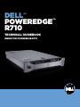
Inside the poweredge R710
Dell™ PowerEdge™ R710 Technical Guidebook
TABLE OF CONTENTS
Section 1. system overview
A. Overview / Description
B. Product Features Summary
6
6
6
Section 2. Mechanical
A. Chassis Description
B. Dimensions and Weight
C. Front Panel View and Features
D. Back Panel View and Features
E. Power Supply Indicators
F. NIC Indicators
G. Side Views and Features
H. Rails and Cable Management
I. Fans
J. Control Panel / LCD
K. Security
I. Cover Latch
II. Bezel
III. Hard Drive
IV. TPM
V. Power Off Security
VI. Intrusion Alert
VII. Secure Mode
L. USB Key
M. Battery
N. Field Replaceable Units (FRU)
7
7
8
8
8
9
9
9
10
10
11
11
11
12
12
12
12
12
12
12
12
12
Section 3. Electrical
A. Volatility
B. ePPID (Electronic Piece Part Identification)
13
13
13
Section 4. Power, Thermal, Acoustic
A. Power Efficiencies
B. Power Supplies
I. Main Power Supply
C. Power Supply Specifications
D. Environmental Specifications
E. Power Consumption Testing
F. Maximum Input Amps
G. Energy SMART Enablement
H. Acoustics
14
14
14
14
15
16
17
17
17
18
Dell™ PowerEdge™ R710 Technical Guidebook
Section 5. Block Diagram
19
Section 6. Processors
A. Overview / Description
B. Features
C. Supported Processors
D. Processor Configurations
21
21
21
21
22
Section 7. Memory
A. Overview / Description
B. DIMMs Supported
C. Speed
D. Slots / Risers
E. Supported Configurations
F. Mirroring
G. Advanced ECC (Lockstep) Modes
H. Optimizer (Independent Channel) Mode
23
23
23
24
27
27
28
28
28
Section 8. Chipset
A. Overview / Description
29
29
Section 9. BIOS
A. Overview / Description
B. Supported ACPI States
C. I2C (Inter-Integrated Circuit)
31
31
31
32
Section 10. Embedded NICs / LAN on Motherboard (LOM)
A. Overview / Description
32
32
Section 11. I/O Slots
A. Overview / Description
B. PCI Express Risers
C. Additional Riser Restrictions
D. X16 Express Card Specifications
E. Boot Order
33
33
35
35
35
35
Section 12. Storage
A. Overview / Description
B. Drives
I. Internal Hard Disk drives
II. Hard Disk Drive Carriers
III. Empty Drive Bays
IV. Diskless Configuration Support
V. Hard Drive LED Indicators
C. RAID Configurations
36
36
36
36
37
37
38
38
38
Dell™ PowerEdge™ R710 Technical Guidebook
D. Storage Controllers
I. SAS 6/iR
II. PERC 6i
E. LED Indicators
F. Optical Drives
G. Tape Drives
39
39
40
41
41
41
Section 13. Video
A. Overview / Description
42
42
Section 14. Audio
A. Overview / Description
43
43
Section 15. Rack Information
A. Overview / Description
B. Cable Management Arm (CMA) C. Rails
43
43
43
44
Section 16. Operating Systems
A. Overview / Description
45
45
Section 17. Virtualization
A. Overview / Description
47
47
Section 18. Systems Management
A. Overview / Description
B. Server Management
C. Embedded Server Management
I. Unmanaged Persistent Storage
II. Lifecycle Controller/Unified Server Configurator
III. iDRAC6 Express
IV. iDRAC6 Enterprise
47
47
47
48
48
48
49
49
Section 19. Peripherals
A. USB peripherals
B. External Storage
52
52
52
Section 20. Documentation
A. Overview, Description, and List
53
53
Section 21. Packaging Options
53
appendix
54
Dell™ PowerEdge™ R710 Technical Guidebook
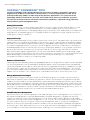
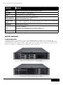
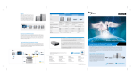
The Dell™ PowerEdge™ R710
The Dell PowerEdge R710 is designed to be the cornerstone of today’s competitive enterprise.
Engineered in response to input from IT professionals, it is the next-generation 2U rack server
created to efficiently address a wide range of key business applications. The successor to the
PowerEdge 2950 III, the R710 runs the Intel® Xeon® 5500 Series Processors and helps you lower
the total cost of ownership with enhanced virtualization capabilities, improved energy efficiency,
and innovative system management tools.
Strong IT Foundation
As an IT professional, you want a data center built to allow for organic growth and the ability to scale
based on your company’s changing requirements. You need complete solutions that allow you to
focus your time and money on managing and growing your business. Dell understands your needs and
responds with an expanding portfolio of enterprise servers, storage technologies, and services with a
single goal: to help you simplify IT.
Purposeful Design
The R710 takes advantage of Dell’s system commonality. Once your IT managers learn one system, they
understand how to manage next-generation Dell servers. Logical component layout and power supply
placement also provide a straightforward installation and redeployment experience. Featuring 18 DIMM
slots and 4 integrated network connections, the R710 delivers the critical components to virtualization
and database performance. The Intel Xeon Processor 5500 Series adapts to your software in real time,
processing more tasks simultaneously. Using Intel® Turbo Boost Technology, the R710 can increase
performance during peak usage periods. You can then help reduce operating costs and energy usage
with Intel® Intelligent Power Technology, which proactively puts your server into lower power states when
demand decreases. Increased memory slots also save money by enabling you to use smaller,
less-expensive DIMMs to meet your computing needs.
Enhanced Virtualization
Featuring Intel Xeon-based architecture, embedded hypervisors, large memory capacity, and integrated
I/O, the next-generation Dell PowerEdge R710 delivers better overall system performance and greater
virtual machine-per-server capacity. With optional factory-integrated virtualization capabilities, you get
tailored solutions – built with the latest technologies from Dell and our trusted partners – which allow
you to streamline deployment and simplify virtual infrastructures. Choose your hypervisor from market
leaders such as VMware®, Citrix®, and Microsoft®, and enable virtualization with a few mouse clicks.
Energy-Optimized Technologies
Using the latest Energy Smart technologies, the R710 reduces power consumption while increasing
performance capacity versus the previous generation servers. Enhancements include efficient power
supply units right-sized for system requirements, improved system-level design efficiency, policy-driven
power and thermal management, and highly efficient standards-based Energy Smart components. Dell's
advanced thermal control delivers optimal performance at minimal system and fan power consumption
resulting in our quietest 2U servers to date. These enhancements maximize energy efficiency across our
latest core data center servers without compromising enterprise performance.
Simplified Systems Management
Gain more control with the next-generation Dell OpenManage™ suite of management tools. These tools
provide enhanced operations and standards-based commands designed to integrate with existing
systems for effective control. Dell Management Console (DMC) helps simplify operations and creates
stability by shrinking infrastructure management to one console. This console delivers a single view and
a common data source into the entire infrastructure management. Built on Symantec® Management
Platform, it has an easily extensible, modular foundation that can provide basic hardware management
all the way up to more advanced functions, such as asset and security management. Dell Management
Console reduces or eliminates manual processes, enabling you to save time and money for more
5
Dell™ PowerEdge™ R710 Technical Guidebook
strategic technology usage. Secure, efficient, and more user friendly than its predecessors, the Dell
Unified Server Configurator (USC) delivers “Instant On” integrated manageability through a single
access point. You get quick, persistent access to the tool because it is embedded and integrated into
the system for increased flexibility and capabilities. The USC is a one-stop shop for deploying operating
systems with built-in driver installations, firmware updates, hardware configuration, and issue diagnoses.
Section 1. System Overview
A. Overview / Description
The PowerEdge R710 will lead Dell's 11th Generation PowerEdge portfolio in key areas of differentiation,
primarily:
• Virtualization
• Power, thermal, efficiency
• Systems management, and usability
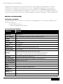
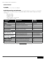
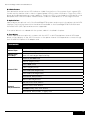
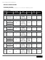
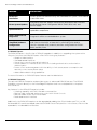
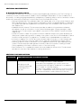
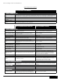
B. Product Features Summary
Feature
Details
Processor
Nehalem EP
Front Side Bus
Intel® QuickPath Interconnect (QPI) @ maximum 6.GT/s
# Procs
2S
# Cores
4 cores
L2/L3 Cache
4MB and 8MB
Chipset
Tylersberg
DIMMs/Speed
18 RDIMM or UDIMM DDR3 (9 per processor)
Min/Max RAM
1GB – 144GB
HD Bays
Internal hard drive bay and hot-plug backplane
Up to six 3.5" SAS or SATA drives without optional flex bay OR
Up to eight 2.5" SAS or SATA drives with optional flex bay
HD Types
SAS, SATA, Near-line SAS, and SSD
Ext Drive Bay(s)
Optional flex-bay expansion to support a half-height TBU
Int. HD Controller
PERC 6i and SAS 6/iR
Opt. HD Controller
BIOS
Video
Based on the Matrox G200 w/iDRAC
Availability
Server
Management
I/O Slots
Two x8 and two x4 PCIe Gen2 slots or One x16 PCIe slot and two x4 PCIe Gen2
6
Dell™ PowerEdge™ R710 Technical Guidebook
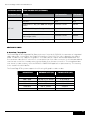
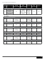
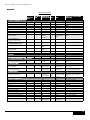
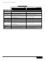
Feature
Details
RAID
PERC 6i utilizing battery backed 256MB DDRII 667
NIC/LOM
Broadcom 5809C (2 cards/4ports)
USB
Five (two front, two rear, one internal)
Power Supplies
Two hot-plug high-efficient 570W PSU OR
Two hot-plug 870W PSUs (1+1)
Front Control
Panel
The system control panel is located on the front of the system chassis to provide
user access to buttons, display, and I/O interfaces
System ID
Front and rear (0x0235)
Fans
Five hot-swappable
Additional fan integrated into each power supply
Single processor configurations will only have four fans
Chassis
2u Rackmount
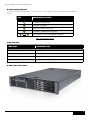
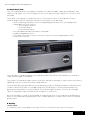
Section 2. Mechanical
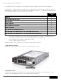
A. Chassis Description
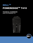
PowerEdge R710 is a 2U rackmount chassis. The updated design includes a new LCD, bezel and
hard-drive carriers. Additional changes include tool-less rack latches, a pull out tray for customer labels,
and LOM0/iDRAC MAC address; labels; support persistent storage (internal USB and SD card slots and
external SD card slots); updated power supplies and removal process.
From view 3.5" HDD Chassis (without bezel)
From view 2.5" HDD Chassis (without bezel)
7
Dell™ PowerEdge™ R710 Technical Guidebook
B. Dimensions and Weight
Height
8.64cm (3.40")
Width
44.31cm (17.44")
Depth
68.07cm (26.80")
Weight (maximum config) 26.1kg (57.54lbs)
.
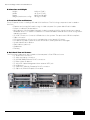
C. Front Panel View and Features
Front I/O panel access including USB and VGA interfaces. The following components are located on
the front:
• Express service tag (Information tag). A slide-out panel for system identification labels
• Power on indicator, power button
• NMI indicator (Nonmaskable interrupt). A device sends an NMI to signal the processor about
hardware errors. It is used to troubleshoot software and device driver errors when using certain
operating systems
• (2) USB connectors. Connects USB devices to the system. The ports are USB 2.0 compliant
• Video connector
• LCD menu buttons. Allows you to navigate the control panel LCD menu
• LCD panel. Provides system ID, status information, and system error messages
• System identification button
• Optical drive (optional)
• Hard drives
• Flex bay
D. Back Panel View and Features
The following components are located on the rear panel of the R710 enclosure:
• (1) 15-pin VGA connector
• (1) 9-pin serial port connector
• (4) 10/100/1000 Ethernet RJ-45 connectors
• (1) Rear system ID button
• (1) Active ID Cable Management Arm external LED jack
• (2) USB ports
• (1) (Optional) iDRAC6 Enterprise RJ-45 connector
• (1) Optional) iDRAC6 Express SD module
8
Dell™ PowerEdge™ R710 Technical Guidebook
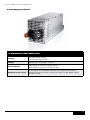
E. Power Supply Indicators
The PSUs on the PE R710 have one status bi-color LED: green for AC power present and amber for
a fault.
led
Power Supply status
AC power is not present
AC power is present
Fault of any kind is detected
DC power is applied to the system
PSU mismatch (when hot-added/swapped)
Table: Power Supply Indicator
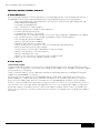
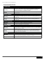
F. NIC Indicators
indicator
indicator code
Link and activity indicators are off
The NIC is not connected to the network
Link indicator is green
The NIC is connected to a valid network link at 1000 Mbps
Link indicator is amber
The NIC is connected to a valid network link at 1000 Mbps
Activity indicator is green blinking
Network data is being sent or received
G. Side Views and Features
9
Dell™ PowerEdge™ R710 Technical Guidebook
H. Rails and Cable Management
Rack installation components such as rails are provided with the PowerEdge R710 Rack Kit. The rack
installation components are as follows: Sliding rack mount with latest generation Cable Management
Arm (CMA). When the system is installed in a rack, please observe the following guideline:
When the system is installed in a rack, only Dell-approved CMAs should be installed behind
the chassis.
Rails
CMAs
• Enable the replacement of thumbscrews with slam latches on the chassis for easier stowing in
the rack.
• Include the new simple and intuitive ReadyRail™ tool-less rack interface for square-hole and
round-hole racks.
• Provide significantly improved compatibility with non-Dell racks.
• Static rails for the R610 & R710 fit in all types of four-post and two-post racks available in the
industry including four-post threaded hole racks.
• Provide much larger vent pattern for improved airflow through the CMA.
• Include a common support tray for eliminating CMA sag.
• Replaced tie wraps with hook and loop straps to eliminate risk of cable damage during cycling.
• Maintain key feature of being fully reversible with no conversion required.
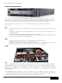
I. Fans
Fans
Five hot-swappable fans are mounted in a fan gantry that is located in the chassis between the hard
drive bay and the processors. Each fan has a blind mate 2x2 connector that plugs directly into the
planar. There is an additional fan integrated in each power supply to cool the power supply subsystem
and also provide additional cooling for the whole system. Single processor configurations will have four
fans populated.
The Embedded Server Management logic in the system monitors the speed of the fans. A fan failure
or over-temperature in the system results in a notification by iDRAC6. All system fans are pulse-width
modulated fans. Redundant cooling is supported with one fan failing at a time.
10
Dell™ PowerEdge™ R710 Technical Guidebook
J. Control Panel / LCD
The control panel board is connected to the planar via a 60-wire ribbon cable and a separate 5-wire
cable for USB signals only. The LCD plugs into the control panel through a 20-pin ZIF connector and
flex cable.
The system control panel is located on the front of the system chassis to provide user access to
switches, display, and I/O interfaces. Features of the system control panel are:
• ACPI-compliant power button with an integrated green power LED (controlled by ESM)
• 128x20 pixel LCD with controls
• Two navigation buttons
• One-select button
• One system ID button
• Non-Maskable-Interrupt (NMI) button (recessed)
• Ambient temperature sensor
• Two external USB 2.0 connectors (with two internal connectors dedicated for UIPS)
• 15-pin VGA connector
The LCD panel is a graphics display controlled by the BMC/ESM. Both ESM and BIOS can send error
codes and messages to the display.
The system’s LCD panel provides system information and status messages to signify when the system is
operating correctly or when the system needs attention.
The LCD backlight lights blue during normal operating conditions and lights amber to indicate an error
condition. When the system is in standby mode, the LCD backlight is off and can be turned on by
pressing the Select button on the LCD panel. The LCD backlight will remain off if the “No Message"
option is selected through the iDRAC6, the LCD panel, or other tools.
BIOS has the ability to enter a “Secure Mode" through Setup, which locks the power and NMI buttons.
When in this mode, pressing either button has no effect but does not mask other sources of NMI and
power control.
K. Security
I. Cover Latch
A tooled entry latch is provided on the top of the unit to secure the top cover to the chassis
11
Dell™ PowerEdge™ R710 Technical Guidebook
II. Bezel
A metal bezel is mounted to the chassis front to provide the Dell ID. A lock on the bezel is used to
protect un-authorized access to system peripherals and the control panel. System status via the LCD is
viewable even when the bezel is installed.
III. Hard Drive
The optional front bezel of the system contains a lock. A locked bezel secures the system hard drives.
IV. TPM
The TPM is used to generate/store keys, protect/authenticate passwords, and create/store digital
certificates. TPM can also be used to enable the BitLocker™ hard drive encryption feature in Windows
Server® 2008. TPM is enabled through a BIOS option and uses HMAC-SHA1-160 for binding. There will be
different planar PWA part numbers to accommodate the different TPM solutions. The “Rest of World"
(ROW) version will have the TPM soldered onto the planar. The other version of the planar (post RTS
and primarily for use by China) will have a connector for a plug-in module.
V. Power Off Security
The control panel is designed such that the power switch cannot be accidentally activated. The lock on
the bezel secures the switch behind the bezel. In addition, there is a setting in the CMOS setup that
disables the power button function.
VI. Intrusion Alert
A switch mounted on the left riser board is used to detect chassis intrusion. When the cover is opened,
the switch circuit closes to indicate intrusion to ESM. When enabled, the software can provide
notification to the customer that the cover has been opened.
VII. Secure Mode
BIOS has the ability to enter a secure boot mode via Setup. This mode includes the option to lock out
the power and NMI switches on the Control Panel or set up a system password. See the 11th generation
of PowerEdge servers BIOS Specification for details
L. USB Key
The port on the control panel is for an optional USB key and is located inside the chassis. Some of the
possible applications of the USB key are:
• User custom boot and pre-boot OS for ease of deployment or diskless environments
• USB license keys for software applications like eToken™ or Sentinel Hardware Keys
• Storage of custom logs or scratch pad for portable user defined information (not hot-swappable)
M. Battery
A replaceable coin cell CR2032 3V battery is mounted on the planar to provide backup power for the
Real-Time Clock and CMOS RAM on the ICH9 chip.
N. Field Replaceable Units (FRU)
The planar contains a serial EEPROM to contain FRU information including Dell part number, part
revision level, and serial number. The Advanced Management Enablement Adapter (AMEA) also
contains a FRU EEPROM. The backplane’s SEP and the power supplies’ microcontroller are also used to
store FRU data.
12
Dell™ PowerEdge™ R710 Technical Guidebook
Section 3. Electrical
A. Volatility
See Appendix A of this Technical Guidebook
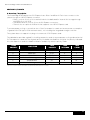
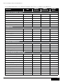
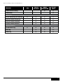
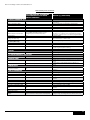
B. ePPID (Electronic Piece Part Identification)
ePPID is an electronic repository for information from the PPID label that is stored in non-volatile RAM.
The BIOS reports the ePPID information using SMBIOS data structures. ePPID includes the following
information:
• Dell part number
• Part revision level
• Country of origin
• Supplier ID code
• Date code (date of manufacture)
• Unique sequence number
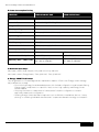
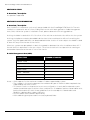
COMPOnent
description
storage
location
BOARDS
Planar
PWA,PLN,SV,DELL,R710
iDRAC FRU
2.5" x 8' Backplane
PWA,BKPLN,SV,R710,2.5SASX8
SEP
3.5" x 6' Backplane
PWA,BKPLN,SV,R710,3.5SASX6
SEP
3.5" x 4' Backplane
PWA,BKPLN,SV,R710,3.5SASX4
SEP
iDRAC Enterprise
PWA,RSR, SV, DELL,AMEA
FRU
PWR SPLY,885W,RDNT,ASTEC
PSU Microcontroller
PWR SPLY,885W,RDNT,DELTA
PSU Microcontroller
PWR SPLY,598W,RDNT,ASTEC
PSU Microcontroller
PWR SPLY,598W,RDNT,COLDWATT
PSU Microcontroller
PERC 6/i Integrated
ASSY,CRD,PERC6I-INT,SAS,NOSLED
FRU
PERC 6/E External
PWA,CTL,PCIE,SAS,PERC6/E,ADPT
FRU
SAS 6/iR Integrated
PWA,CTL,SAS,SAS6/IR,INTG
FRU
Power supplies
870W PowerEdge™ PSU
570W Energy Smart PSU
storage cards
Table: ePPID Support list
Note: The fans do not have any integrated NVRAM. The PPID tables are currently scanned into a database by the system integrator.
13
Dell™ PowerEdge™ R710 Technical Guidebook
Section 4. Power, Thermal, Acoustic
A. Power Efficiencies
One of the main features of the 11th generation of PowerEdge servers is enhanced power efficiency.
PowerEdge R710 achieves higher power efficiency by implementing the following features:
• User-selectable power cap (subsystems will throttle to maintain the specified power cap)
• Improved power budgeting
• Accurate inlet temperature
• PSU / VR efficiency improvements
• Switching regulators instead of linear regulators
• Closed loop thermal throttling
• Increased rear venting / 3D venting
• PWM fans with an increased number of fan zones and configuration-dependent fan speeds
• Use of DDR3 memory (lower voltage compared to DDR2, UDIMM support)
• CPU VR dynamic phase shedding
• Memory VR static phase shedding
• Random time interval for system start
• Allows an entire rack to power on without exceeding the available power
• BIOS Power/Performance options page
• Active Power Controller (BIOS-based CPU P-state manager)
• Ability to power down or throttle memory
• Ability to disable a CPU core
• Ability to turn off LOMs or PCIe lanes when not being used
• Option to run PCIe at Gen1 speeds instead of Gen2
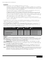
B. Power Supplies
I. Main Power Supply
The base redundant system consists of two hot-plug 570W Energy Smart (energy efficient) power
supplies in a 1+1 configuration. An 870W high-output power supply is also available. The power supplies
connect directly to the planar.
There is a power cable to connect between the planar and the backplane. PowerEdge R710 power
supplies have embedded cooling fans.
Starting with the 11th generation of PowerEdge servers (R710, R610, T610, M610, and M710), the
power supplies no longer have a FRU EEPROM. FRU data is now stored in the memory of the PSU
Microcontroller. Additionally, the PSU Firmware can now be updated by the BMC over the PMBus.
Power is “soft-switched,” allowing power cycling via a switch on the front of the system enclosure, or
via software control (through server management functions). In a single power supply configuration,
the power supply is installed in the PS1 location and a blank module (metal cover) is installed in the
PS2 location for factory consistency. Electrically, the system can operate with a single power supply in
either bay.
14
Dell™ PowerEdge™ R710 Technical Guidebook
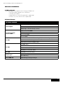
C. Power Supply Specifications
AC Power supply (per power supply)
Wattage
870 Watt (High Output)
570 Watt (Energy Smart)
Voltage
90-264 VAC, autoranging, 47-63Hz
Heat Dissipation
2968.6 BTU/hr maximum (High Output)
1944.9 BTU/hr maximum (Energy Smart)
Maximum Inrush Current
Under typical line conditions and over the entire system ambient
operating range, the inrush current may reach 55A per power supply
for 10ms or less.
15
Dell™ PowerEdge™ R710 Technical Guidebook
D. Environmental Specifications
temperature
Operating
10° to 35°C (50° to 95°F) with a maximum temperature gradation of
10°C per hour. Note: For altitudes above 2950 feet, the maximum
operating temperature is derated 1°F/550 ft.
Storage
-40° to 65°C (-40° to 149°F) with a maximum temperature gradation of
20°C per hour
Relative humidity
Operating
20% to 80% (noncondensing) with a maximum humidity gradation of
10% per hour
Storage
5% to 95% (noncondensing) with a maximum humidity gradation of
10% per hour
Maximum vibration
Operating
0.26 Grms at 5-350Hz in operational orientations
Storage
1.54 Grms at 10-250Hz in all orientations
Maximum shock
Operating
Half sine shock in all operational orientations of 31G +/- 5% with a pulse
duration of 2.6 ms +/-10%
Storage
Half sine shock on all six sides of 71G +/- 5% with a pulse duration of
2 ms +/-10%: Square wave shock on all six sides of 27G with velocity
change @ 235 in/sec or greater
Altitude
Operating
-16 to 3048 m (-50 to 10,000 ft) Note: For altitudes above 2950 feet, the
maximum operating temperature is derated 1°F/550 ft.
Storage
-16 to 10,600 m (-50 to 35,000 ft)
16
Dell™ PowerEdge™ R710 Technical Guidebook
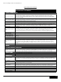
E. Power Consumption Testing
Feature
1
Energy Smart PSU
High Output PSU
Dimensions
L-206.4 mm1 x W-67.5 mm x H-76.5 mm
Status Indicators
1 x bi-color Light Emitting Diode
Integrated Fans
1 x 60 mm
Fixed Input Plug
IEC-C14
AC Cord Rating
15 Amps @ 120 VAC, 10 Amps @ 240 VAC
Input Voltage
90 – 264 VAC
Auto-ranging
Yes
Line Frequency
47 – 63Hz
Maximum Inrush Current
55 Amps per supply for 10 ms or less
Hot-Swap Capability
Yes
Output Power
570W
870W
Maximum Heat Dissipation
1944.9 BTU per hour
2968.6 BTU per hour
Efficiency (20% - 100% Load)
86.9 – 90.5% @ 115 VAC
88 – 92% @ 230 VAC
85 – 88% @ 115 VAC
87 – 90% @ 230 VAC
Does not include the power supply handle or ejection tab
F. Maximum Input Amps
Max input current (High Output): 12A @ 90 VAC, 6A @ 180 VAC
Max input current (EnergySmart): 7.8A @ 90 VAC, 3.9A @ 180 VAC
G. Energy SMART Enablement
The 11th generation of PowerEdge servers implements aspects of Dell’s new Energy Smart strategy.
Major differences include:
• Discontinuing Energy Smart-branded servers with limited configurations and instead offering
Energy Smart components on a portfolio level, such as high capacity and Energy Smart
power supplies
• Allowing customers to order either a lowest power footprint configuration or a best
performance-per-watt configuration
• Offering Energy Smart selected components such as DIMMs or hard drives, but not “cherry
picking" or screening individual manufacturers’ components based on energy consumption.
17
Dell™ PowerEdge™ R710 Technical Guidebook
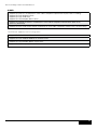
H. Acoustics
The acoustical design of the PowerEdge R710 reflects the following:
• Adherence to Dell’s high sound quality standards. Sound quality is different from sound power
level and sound pressure level in that it describes how humans respond to annoyances in sound,
like whistles, hums, etc. One of the sound quality metrics in the Dell specification is prominence
ratio of a tone, and this is listed in the table below.
• Office environment acoustics. Compare the values for LpA in the table below and note that
they are lower than ambient noise levels of typical office environments.
• Hardware configurations affect system noise levels. Dell’s advanced thermal control provides
for optimized cooling with varying hardware configurations. Most typical configurations will
perform as listed in the table below. However some less typical configurations and components
can result in higher noise levels. For example, a system configured with a PERC6/E card will be
approximately twice as loud ( 9 dBA higher) in 23+/-2° C ambient.
• Noise ramp and descent at Bootup. Fan speeds hence noise levels ramp during the boot
process in order to add a layer of protection for component cooling in the case that the system
were not to boot properly.
~
PowerEdge R710 (2.5" and 3.5" chassis) with RK385 fans (quantity below), 2x 870-W FU096 Power
Supplies, 2.40 GHz Quad-Core E5530 CPUs (quantity below), 7x 2-GB DIMMs, 1x DVD Drive, Perc 6i
card, and 4x Hard Disk Drives (type below)
Acoustical dependence on quantities of fans, CPUs, and Hard Disk Drive type is not strong. The values
below represent therefore the performance for redundant (5x fans and 2x CPUs) as well as the
nonredundant (4x fans and 1x CPU) configurations. They also represent performance for 2.5" 10k SAS
XK112 as well as 3.5" 7.2k SATA NW340 Hard Disk Drives.
_ 2° C ambient
Condition in 23 +
LwA-UL, bels
LpA, dBA
Tones
Standby
3.1
18
No prominent tones
Idle
5.5
39
No prominent tones
Active Hard Disk Drives
5.5
39
No prominent tones
Stressed Processor
5.5
39
No prominent tones
Definitions
Standby: AC Power is connected to Power Supply Units but system is not turned on.
Idle: Reference ISO7779 (1999) definition 3.1.7; system is running in its OS but no other specific activity.
Active Hard Drives: An operating mode per ISO7779 (1999) definition 3.1.6; Section C.9 of ECMA-74
9th ed. (2005) is followed in exercising the hard disk drives.
Stressed Processor: An operating mode per ISO7779 (1999) definition 3.1.6; SPECPower set to 50%
loading is used.
LwA-UL: The upper limit sound power level (LwA) calculated per section 4.4.2 of ISO 9296 (1988) and
measured in accordance with ISO7779 (1999).
LpA: The average bystander position A-weighted sound pressure level calculated per section 4.3 of
ISO9296 (1988) and measured in accordance with ISO7779 (1999). The system is placed in a
rack with its bottom at 25-cm from the floor.
Tones: Criteria of D.5 and D.8 of ECMA-74 9th ed. (2005) are followed to determine if discrete tones are
prominent. The system is placed in a rack with its bottom at 75-cm from the floor. The acoustic
transducer is at front bystander position, ref ISO7779 (1999), Section 8.6.2.
18
Dell™ PowerEdge™ R710 Technical Guidebook
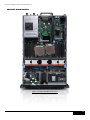
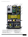
Section 5. Block Diagram
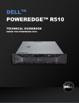
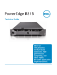
Figure: PowerEdge R710 Main Components
19
Dell™ PowerEdge™ R710 Technical Guidebook
1
2
3
4
5
6
7
8
8
9
11
10
1. Embedded Network Interface Ports (4)
2. PCIe Gen2 Riser / Slots
3. Broadcom 5709c Network Interface Chip
4. PCIe Gen2 Riser / Slots
5. iDRAC6 Enterprise (Optional)
6. iDRAC6 Express / Lifecycle Controller
7. Heat Sink / Processor Socket
8. DIMM Slots
9. Hot plug, redundant fans
10. Hard drive bay, 6" x 3.5"
11. Internal SD Module
(Embedded Hypervisor Optional)
20
Dell™ PowerEdge™ R710 Technical Guidebook
Section 6. Processors
A. Overview / Description
The Intel 5500 series 2S processor (Nehalem - Efficient Processor (EP)), is the microprocessor designed
specifically for servers and workstation applications. The processor features quad-core processing to
maximize performance and performance/watt for data center infrastructures and highly dense
deployments. The Nehalem-EP 2S processor also features Intel’s Core™ micro-architecture and Intel
64 architecture for flexibility in 64-bit and 32-bit applications and operating systems.
The 5500 series 2S processor (Nehalem EP) utilizes a 1366-contact Flip-Chip Land Grid Array (FC-LGA)
package that plugs into a surface mount socket. PowerEdge R710 provides support for up to two 5500
series 2S processors (Nehalem EP).
Nehalem-EP 2S Processor
Cache Size
Features
32KB instruction, 32KB data, 4 or 8MB (shared)
Multi-processor Support
1-2 CPUs
Package
LGA1366
Table: Nehalem-EP Features
B. Features
Key features of the 5500 series 2S processor (Nehalem EP) include:
• Four or two cores per processor
• Two point-to-point QuickPath Interconnect links at up to 6.4 GT/s
• 1366-pin FC-LGA package
• 45 nm process technology
• No termination required for non-populated CPUs (must populate CPU socket 1 first)
• Integrated three-channel DDR3 memory controller at up to 1333MHz
• Compatible with existing x86 code base
• MMX™ support
• Execute Disable Bit Intel Wide Dynamic Execution
• Executes up to four instructions per clock cycle
• Simultaneous Multi-Threading (Hyper-Threading) capability
• Support for CPU Turbo Mode (on certain SKUs)
• Increases CPU frequency if operating below thermal, power, and current limits
• Streaming SIMD (Single Instruction, Multiple Data) Extensions 2, 3, and 4
• Intel 64 Tecnology for Virtualization
• Intel VT-x and VT-d Technology for Virtualization
• Demand-based switching for active CPU power management as well as support for ACPI
P-States, C-States, and T-States
C. Supported Processors
model
speed
power
cache
cores
X5570
2.93GHz
95W
8M
4
X5560
2.80GHz
95W
8M
4
X5550
2.66GHz
95W
8M
4
E5540
2.53GHz
80W
8M
4
21
Dell™ PowerEdge™ R710 Technical Guidebook
model
speed
power
cache
cores
E5530
2.40GHz
80W
8M
4
E5520
2.26GHz
80W
8M
4
L5520
2.26GHz
60W
8M
4
E5506
2.13GHz
80W
4M
4
L5506
2.13GHz
60W
4M
4
E5504
2.00GHz
80W
4M
4
E5502
1.86GHz
80W
4M
2
D. Processor Configurations
Single CPU Configuration
The PowerEdge R710 is designed such that a single processor placed in the CPU1 socket will function
normally, however PowerEdge R710 systems require a CPU blank in the CPU2 socket for thermal reasons.
The system will be held in reset if a single processor is placed in the CPU2 socket.
Performance Enhancements
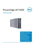
Intel® Turbo Boost Technology
Intel Xeon 5500 Series Processor (Nehalem-EP)
®
Intel® Turbo Boost
Technology
Intel® Hyper-Threading
Technology
Increases performance by increasing processor
frequency and enabling faster speeds when
conditions allow
Increases performance for threading applications
delivering greater throughput and responsiveness
Normal
Cores / Threads
4C Turbo <4C Turbo
Core Core
Core 0Core 1
0
1
Core Core
Core 2Core 3
2
3
(2 socket/HT on)
Core IDLE
Core 0IDLE
0
IDLE IDLE
IDLE IDLE
2
16
TURBO Freq
BASE Freq
Benefit
3.20 GHz
up to 6%†
2.93 GHz
for 16 concurrent
software threads
3.33 GHz
up to 10%
2.93 GHz
for 2 software
threads
Core 0
Core 1
Core 2
Core 3
All cores
operate
at rated
frequency
All cores
operate
at higher
frequency
Core 0
Core 1
Core 1
Core 1
Core 2
Core 3
Frequency
OR
Fewer cores
may operate
at even higher
frequencies
Higher performance
on demand
Higher performance
for threaded workloads
(2 socket/HT on)
Improves application responsiveness
Delivers higher processor frequency on demand
model
speed
power
cache
cores
X5570
2.93GHz
95W
8M
4
X5560
2.80GHz
95W
8M
4
X5550
2.66GHz
95W
8M
4
E5540
2.53GHz
80W
8M
4
E5530
2.40GHz
80W
8M
4
E5520
2.26GHz
80W
8M
4
L5520
2.26GHz
60W
8M
4
E5506
2.13GHz
80W
4M
4
L5506
2.13GHz
60W
4M
4
E5504
2.00GHz
80W
4M
4
E5502
1.86GHz
80W
4M
2
22
Dell™ PowerEdge™ R710 Technical Guidebook
CPU Power Voltage Regulation Modules (EVRD 11.1)
Voltage regulation to the 5500 series 2S processor (Nehalem EP) is provided by EVRD (Enterprise
Voltage Regulator-Down). EVRDs are embedded on the planar. CPU core voltage is not shared between
processors. EVRDs support static phase shedding and power management via the PMBus.
Section 7. Memory
A. Overview / Description
The PowerEdge R710 utilizes DDR3 memory providing a high performance, high-speed memory
interface capable of low latency response and high throughput. The PE R710 supports Registered
ECC DDR3 DIMMs (RDIMM) or Unbuffered ECC DDR3 DIMMs (UDIMM).
Key features of the PowerEdge R710 memory system include:
• Registered (RDIMM) and Unbuffered (UDIMM) ECC DDR3 technology
• Each channel carries 64 data and eight ECC bits support for up to 96GB of RDIMM memory
(with twelve 8GB RDIMMs)
• Support for up to 24GB of UDIMM memory (with twelve 2GB UDIMMs)
• Support for 1066/1333MHz single- and dual-rank DIMMs
• Support for 1066MHz quad rank DIMMs
• Single DIMM configuration only with DIMM in socket A1
• Support ODT (On Die Termination) Clock gating (CKE) to conserve power when DIMMs
are not accessed
• DIMMs enter a low-power self-refresh mode
• I2C access to SPD EEPROM for access to RDIMM thermal sensors
• Single Bit Error Correction
• SDDC (Single Device Data Correction – x4 or x8 devices)
• Support for Closed Loop
• Thermal Management on RDIMMs and UDIMMs
• Multi Bit Error Detection Support for Memory Optimized Mode
• Support for Advanced ECC mode
• Support for Memory Mirroring
B. DIMMs Supported
The DDR3 memory interface consists of three channels, with up to two RDIMMs or UDIMMs per
channel for single-/dual-rank and up to two RDIMMs per channel for quad rank. The interface uses 2GB,
4GB, or 8GB RDIMMs. 1GB or 2GB UDIMMs are also supported. The memory mode is dependent on how
the memory is populated in the system:
Three channels per CPU populated identically:
• Typically, the system will be set to run in Memory Optimized (Independent Channel) mode in
this configuration. This mode offers the most DIMM population flexibility and system memory
capacity, but offers the least number of RAS (reliability, availability, service) features.
• All three channels must be populated identically.
• Users wanting memory sparing must also populate the DIMMs in this method, but one channel
is the spare and is not accessible as system memory until it is brought online to replace a failing
channel.
• The first two channels per CPU populated identically with the third channel unused
• Typically, two channels operate in Advanced ECC (Lockstep) mode with each other by
having the cache line split across both channels. This mode provides improved RAS
features (SDDC support for x8-based memory).
• For Memory Mirroring, two channels operate as mirrors of each other — writes go to
both channels and reads alternate between the two channels.
23
Dell™ PowerEdge™ R710 Technical Guidebook
• One channel per CPU populated:
• This is a simple Memory Optimized mode. Mirroring is not supported.
The PowerEdge R710 memory interface supports memory demand and patrol scrubbing, single-bit
correction and multi-bit error detection. Correction of a x4 or x8 device failure is also possible with
SDDC in the Advanced ECC mode. Additionally, correction of a x4 device failure is possible in the Memory
Optimized mode. If DIMMs of different speeds are mixed, all channels will operate at the fastest common
frequency. RDIMMs and UDIMMs cannot be mixed.
• If memory mirroring is enabled, identical DIMMs must be installed in the same slots across both
channels.
• The third channel of each processor is unavailable for memory mirroring.
• The first DIMM slot in each channel is color-coded with white ejection tabs for ease of
installation.
• The DIMM sockets are placed 450 mils (11.43 mm) apart, center-to-center in order to provide
enough space for sufficient airflow to cool stacked DIMMs.
• The PE R710 memory system supports up to 18 DIMMs. DIMMs must be installed in each channel
starting with the DIMM farthest from the processor. Population order will be identified by the
silkscreen designator and the System Information Label (SIL) located on the chassis cover.
• Memory Optimized: {1, 2, 3}, {4, 5, 6}, {7, 8, 9}
• Advanced ECC or Mirrored: {2, 3}, {5, 6}, {8, 9}
• Quad Rank or UDIMM: {1, 2, 3}, {4, 5, 6}, {7, 8, 9}
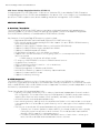
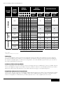
C. Speed
Memory Speed Limitations
The memory frequency is determined by a variety of inputs:
• Speed of the DIMMs
• Speed supported by the CPU
• Configuration of the DIMMs
24
Dell™ PowerEdge™ R710 Technical Guidebook
The table below shows the memory populations and the maximum frequency achievable for that
configuration.
dimm type
UDIMM
RDIMM
DImm 0
dimm 1
dimm 2
# of dimms
SR
1
DR
1
SR
SR
2
SR
DR
2
DR
DR
2
SR
1
DR
1
QR
1
SR
SR
2
SR
DR
2
DR
DR
2
QR
SR
2
QR
DR
2
QR
QR
2
SR
SR
SR
3
SR
SR
DR
3
SR
DR
DR
3
DR
DR
DR
3
800
1066
1333
Note: For QR mixed with an SR/DR DIMM, the QR needs to be in the white DIMM connector. There is no requirement in the order of SR and DR DIMMs.
Supported
Not Supported
NOTE: For Quad Rank DIMMs mixed with Single- or Dual-Rank DIMMs, the QR DIMM needs to be in the slot with the white ejection tabs (the first DIMM slot in each channel).
There is no requirement for the order of SR and DR DIMMs
25
Dell™ PowerEdge™ R710 Technical Guidebook
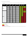
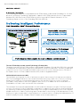
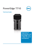
NHM-EP Platform Memory Overview
•P
latform capability (18 DIMMs):
– Up to 3 channels per CPU
– Up to 3 DIMMS per channel
1
•M
emory Types Supported:
– DDR 1333, 1066, and 800
– Registered (RDIMM) and unbuffered (UDIMM)
– Single-rank (SR), dual-rank (DR), quad-rank (QR)
Up to 3
channels
per CPU
2
NHM-EP
NHM-EP
3
1 2 3
Up to 3
DIMMs per
Channel
• System memory Speed (i.e. the speed at which the memory is
actually running) is set by BIOS depending on:
– CPU capability
– DIMM type(s) used (memory speed, U/RDIMM, SR/DR/QR)
– DIMM populated per channel
• All channels in a system will run at the fastest common frequency
Memory Population Scenarios
• Maximum B/W:
– DDR3 1333 across 3 channels
– 1 DPC (6 DIMMs)
– Max capacity: 48 GB+
• Balanced Performance:
– DDR3 1066 across 3 channels
– Up to 2 DIMMs per Channel
(DPC) (12 DIMMs)
– Max capacity: 96 GB+
• Maximum capacity:
– DDR3 800 across 3 channels
– Up to 3 DPC (18 DIMMs total)
– Max capacity: 144 GB+
• RAS capabilities:
CPUs
10.6 GB/s
10.6
CPU
CPU
10.6
8.5 GB/s
8.5
CPU
CPU
8.5
Channel
2 unused
E5520
and above
6.4 GB/s
6.4
CPU
CPU
6.4
Mirroring
Channel
0&1
mirror
each other
E5550
and above
CPU
All
NHM-EP
SKUs
Lockstep
Channel
0&1
operate in
lockstep
CPU
Channel
2 unused
26
Dell™ PowerEdge™ R710 Technical Guidebook
D. Slots / Risers
The PowerEdge R710 has 18 DIMM slots for memory. It does not have any riser cards for DIMM population.
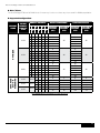
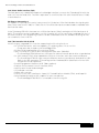
E. Supported Configurations
memory
mode
RDIMM
Memory
Module
Size
memory sockets
1
2
4
3
5
6
x
OPTIMIZER
2GB
4GB
Advanced
ECCb or
mirroring
8GBa
x
x
x
x
x
x
x
x
x
x
x
x
x
x
x
x
x
x
x
x
x
x
x
x
x
x
x
x
x
x
x
x
x
x
x
x
x
x
x
x
2GB
None
4GB
None
8GB
None
x
x
x
x
x
x
x
x
x
x
x
x
x
x
x
x
x
x
x
x
x
x
x
x
x
x
x
x
x
x
x
x
x
x
single processor
physical
memory
(GB)
available
memory
(GB)
dual processor
physical
memory
(GB)
2
4
4
6
4
8
12
4
8
12
8
16
24
8
16
24
16
32
48
4
8
8
16
16
32
8
12
8
16
24
8
16
24
16
32
48
16
32
48
32
64
96
8
16
16
32
32
64
All
All
All
2
4
4
8
8
16
available
memory
(GB)
All
All
All
4
8
8
16
16
32
Table: RDIMM Memory Configurations (Each Processor)
27
Dell™ PowerEdge™ R710 Technical Guidebook
memory
mode
memory
sockets
UDIMM
memory
module
size
1
2
4
single
processor
3
5
6
x
x
x
x
x
x
x
x
x
x
OPTIMIZER
1GB
Advanced
ECCa
2GB
Mirroring
memory
mode
1GB
RDIMM
Memory
Module
2GB
Size
1GB
2GB
physical
memory
(GB)
dual processor
available
memory
(GB)
1
x
x
x
x
x
x
x
x
x
x
x
x
x
x
x
x
x
x
x
x
x
x
None x
x
memory sockets
x x x x
1
2
3
None x
x
4
x
None
x
x
None
5
x
6
x
x
x
x
x
x
x
x
x
x
x
x
2
3
4
6
2
4
6
8
12
physical
memory
(GB)
available
memory
(GB)
2
All
All
2
single processor
All
4
physical available
4
memory
memory
All
(GB)
(GB)
8
4
6
8
12
4
8
12
16
24
All
All
dual
All processor
All
physical
memory
All
(GB)
available
memory
All
(GB)
2
1
4
2
4
2
8
4
4
2
8
4
8
4
16
8
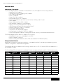
Table: UDIMM Memory Configurations (Each Processor)
a
b
When available
Requires x4- or x8-based memory modules
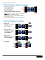
F. Mirroring
The system supports memory mirroring if identical memory modules are installed in the two channels
closest to the processor (memory is not installed in the farthest channel). Mirroring must be enabled in
the System Setup program. In a mirrored configuration, the total available system memory is one-half of
the total installed physical memory.
G. Advanced ECC (Lockstep) Modes
In this configuration, the two channels closest to the processor are combined to form one 128-bit channel.
This mode supports Single Device Data Correction (SDDC) for both x4- and x8-based memory modules.
Memory modules must be identical in size, speed, and technology in corresponding slots.
H. Optimizer (Independent Channel) Mode
In this mode, all three channels are populated with identical memory modules. This mode permits a larger
total memory capacity but does not support SDDC with x8-based memory modules. A minimal singlechannel configuration of 1GB memory modules per processor is also supported in this mode.
28
Dell™ PowerEdge™ R710 Technical Guidebook
Section 8. Chipset
A. Overview / Description
The PowerEdge R710 planar incorporated the Intel 5520 chipset (code named Tylersburg) for I/O and
processor interfacing. Tylersburg is designed to support Intel's 5500 series processors (code named
Nehalem-EP), QPI interconnect, DDR3 memory technology, and PCI Express Generation 2. The
Tylersburg chipset consists of the Tylersburg-36D IOH and ICH9.
The Intel 5520 chipset (code named Tylersburg) I/O Hub (IOH)
The planar uses the The Intel® 5520 chipset (code named Tylersburg) I/O Hub (IOH)-36D IOH to provide
a link between the 5500 series 2S processor (Nehalem EP) and I/O components. The main components
of the IOH consist of two full-width QuickPath Interconnect links (one to each processor), 36 lanes of
PCI Express Gen2, a x4 Direct Media Interface (DMI), and an integrated IOxAPIC.
IOH QuickPath Interconnect (QPI)
The QuickPath Architecture consists of serial point-to-point interconnects for the processors and the
IOH. The PowerEdge R710 has a total of three QuickPath Interconnect (QPI) links: one link connecting
the processors and links connecting both processors with the IOH. Each link consists of 20 lanes
(full-width) in each direction with a link speed of up to 6.4 GT/s. An additional lane is reserved for a
forwarded clock. Data is sent over the QPI links as packets.
The QuickPath Architecture implemented in the IOH and CPUs features four layers. The Physical layer
consists of the actual connection between components. It supports Polarity Inversion and Lane Reversal
for optimizing component placement and routing. The Link layer is responsible for flow control and the
reliable transmission of data. The Routing layer is responsible for the routing of QPI data packets. Finally,
the Protocol layer is responsible for high-level protocol communications, including the implementation of
a MESIF (Modify, Exclusive, Shared, Invalid, Forward) cache coherence protocol.
29
Dell™ PowerEdge™ R710 Technical Guidebook
Intel Direct Media Interface (DMI)
The DMI (previously called the Enterprise Southbridge Interface) connects the Tylersburg IOH with the
Intel I/O Controller Hub (ICH). The DMI is equivalent to a x4 PCIe Gen1 link with a transfer rate of 1 Gb/s
in each direction.
PCI Express Generation 2
PCI Express is a serial point-to-point interconnect for I/O devices. PCIe Gen2 doubles the signaling bit
rate of each lane from 2.5 Gb/s to 5 Gb/s. Each of the PCIe Gen2 ports are backwards-compatible with
Gen1 transfer rates.
In the Tylersburg-36D IOH, there are two x2 PCIe Gen2 ports (1Gb/s) and eight x4 PCIe Gen2 ports (2
Gb/s). The x2 ports can be combined as a x4 link; however, this x4 link cannot be combined with any of
the other x4 ports. Two neighboring x4 ports can be combined as a x8 link, and both resulting x8 links
can combine to form a x16 link.
Intel I/O Controller Hub 9 (ICH9)
ICH9 is a highly integrated I/O controller, supporting the following functions:
• Six x1 PCIe Gen1 ports, with the capability of combining ports 1-4 as a x4 link
• These ports are unused on the PowerEdge R710
• PCI Bus 32-bit Interface Rev 2.3 running at 33MHz
• Up to six Serial ATA (SATA) ports with transfer rates up to 300 MB/s
• The PowerEdge R710 features two SATA port for optional internal optical drive or tape backup
• Six UHCI and two EHCI (High-Speed 2.0) USB host controllers, with up to twelve USB ports
• The PowerEdge R710 has eight external USB ports and two internal ports dedicated for UIPS.
Refer to the 11th generation of PowerEdge servers Hardware/BIOS Specification for the USB
assignments for each platform
• Power management interface (ACPI 3.0b compliant)
• Platform Environmental Control Interface (PECI)
• Intel Dynamic Power Mode Manager
• I/O interrupt controller
• SMBus 2.0 controller
• Low Pin Count (LPC) interface to Super I/O, Trusted Platform Module (TPM), and SuperVU
• Serial Peripheral Interface (SPI) support for up to two devices
• The PowerEdge R710’s BIOS is connected to the ICH using SPI
30
Dell™ PowerEdge™ R710 Technical Guidebook
Section 9. BIOS
A. Overview / Description
The PowerEdge R710 BIOS is based on the Dell BIOS core, and supports the following features:
• Nehalem-EP 2S Support
• Simultaneous Multi-Threading (SMT) support
• CPU Turbo Mode support
• PCI 2.3 compliant
• Plug n’ Play 1.0a compliant
• MP (Multiprocessor) 1.4 compliant
• Boot from hard drive, optical drive, iSCSI drive, USB key, and SD card
• ACPI support
• Direct Media Interface (DMI) support
• PXE and WOL support for on-board NICs
• Memory mirroring and spare bank support
• SETUP access through <F2> key at end of POST
• USB 2.0 (USB boot code is 1.1 compliant)
• F1/F2 error logging in CMOS
• Virtual KVM, CD, and floppy support
• Unified Server Configurator (UEFI 2.1) support
• Power management support including DBS, power inventory and multiple power profiles
The PowerEdge R710 BIOS does not support the following:
• Embedded Diagnostics (embedded in MASER)
• BIOS language localization
• BIOS recovery after bad flash (but can be recovered from iDRAC6 Express)
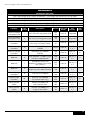
B. Supported ACPI States
Advanced Configuration and Power Interface – A standard interface for enabling the operating system
to direct configuration and power management.
The Nehalem processor supports the following C-States: C0, C1, C1E, C3, and C6. R710 will support all of
the available C-States.
The PowerEdge R710 will support the available P-States as supported by the specific Nehalem processors:
proc
number
qdF #
frequency
standard
tdp
lfm tdp
p-state
1.60
Pmin+0
1.73
Pmin+1
notes
E5502
Q1G8
1.86
80
75
Pmin+2
D-0
E5504
Q1GM
2.00
80
75
Pmin+3
D-0
L5506
Q1HG
2.13
60
52
Pmin+4
D-0
E5506
Q1GL
2.13
80
75
Pmin+4
D-0
L5520
Q1GN
2.26
60
52
Pmin+5
D-0
E5520
Q1GR
2.26
80
75
Pmin+5
D-0
E5530
Q1GK
2.40
80
75
Pmin+6
D-0
31
Dell™ PowerEdge™ R710 Technical Guidebook
proc
number
qdF #
frequency
standard
tdp
lfm tdp
p-state
notes
E5540
Q1G2
2.53
80
75
Pmin+7
D-0
X5550
Q1GJ
2.67
95
75
Pmin+8
D-0
X5560
Q1GF
2.80
95
75
Pmin+9
D-0
X5570
Q1G9
2.93
95
75
Pmin+10
D-0
W5580
Q1G6
3.20
130
98
Pmin+12
D-0
Table: Nehalem P-State Projections
C. I2C (Inter-Integrated Circuit)
What is I2C? A simple bi-directional 2-wire bus for efficient inter-integrated circuit control. All I2C-bus
compatible devices incorporate an on-chip interface which allows them to communicate directly with
each other via the I2C-bus. This design concept solves the many interfacing problems encountered
when designing digital control circuits. These I2C devices perform communication functions between
intelligent control devices (e.g., microcontrollers), general-purpose circuits (e.g., LCD drivers, remote
I/O ports, memories), and application-oriented circuits.
The PowerEdge R710, BIOS accesses the I2C through the ICH9 (Intel I/O Controller Hub 9). There are two
MUXes on ICH9’s I2C bus.
• One MUX (U_ICH_SPD) controls the DIMM SPDs through four split segments
• The other MUX (U_ICH_MAIN) controls the clock buffers, TOE, USB Hub through four split
segments.
BIOS controls both the MUXes through the two select lines using GPIO pins.
Clock chip, USB hub, and the front panel EEPROM device addresses are located on the IOH I2C bus.
Section 10. Embedded NICs / LAN on Motherboard (LOM)
A. Overview / Description
Embedded Gigabit Ethernet Controllers with TCP Offload Engine (TOE) support
Two embedded Broadcom 5709C dual-port LAN controllers are on the R710 planar as independent
Gigabit Ethernet interface devices. The following information details the features of the LAN devices.
• x4 PCI Express Gen2 capable interface
• The PowerEdge R710 operates this controller at Gen1 speed
• Integrated MAC and PHY 3072x18 Byte context memory
• 64 KB receive buffer
• TOE (TCP Offload Engine)
• iSCSI controller (enabled through an optional hardware key)
• RDMA controller (RNIC) (enabled post-RTS through an optional hardware key)
• NC-SI (Network Controller-Sideband Interface) connection for manageability
• Wake-On-LAN (WOL)
• PXE 2.0 remote boot
• iSCSI boot
• IPv4 and IPv6 support
• Bare metal deployment support
32
Dell™ PowerEdge™ R710 Technical Guidebook
Section 11. I/O Slots
A. Overview / Description
The PowerEdge R710 requires two PCI Express risers: Riser 1 and Riser 2. Each riser connects to the
planar through an x16 PCI Express connector.
• Riser 1 consists of two x4 slots and a third x4 slot dedicated for internal SAS storage through
the PERC 6i or SAS 6/iR.
• The default Riser 2 consists of two x8 PCI Express connectors.
• There is also an optional x16 Riser 2 that supports one x16 PCI Express card.
To ensure proper cooling, no more than two of the four expansion cards can have a power consumption
of greater than 15W (up to 25W maximum each), not including the integrated storage controller.
The system does not support hot-plug or hot-removal of PCI Express cards.
The table below provides a guide for installing expansion cards to ensure proper cooling and mechanical
fit. The expansion cards with the highest priority should be installed first using the slot priority indicated.
All other expansion cards should be installed in card priority and slot priority order.
card
priority
a
b
card type
slot
priority
Max
allowed
25W
Card?
1
PERC 5/E controller
1, 3, 4
2
Y
2
PERC 6/E
3, 4, 1
2
Y
3
10Gb NIC
3, 4, 1, 2
2
Y
4
All other Dell storage cards
3, 4, 1
2
Y
5
All other NICs
2, 1
4a
Nb
6
Non-Dell storage cards
1, 2
4a
Nb
Maximum of 2 of any card whose maximum power exceeds 15w
Refer to the expansion card’s documentation to determine if the maximum power exceeds 15w
33
Dell™ PowerEdge™ R710 Technical Guidebook
Poweredge R710
PCI Express Gen2 Slots
Slot 1: Half-Length (6.6" Factory Installation) / Full-Height (x8 connector), x4 link width
Slot 2: Full-Length (12.2" Factory Installation) / Full-Height (x8 connector), x8 link width
Slot 3: Full-Length (12.2" Factory Installation) / Full-Height (x8 connector), x8 link width
Slot 4: Half-Length (6.6" Factory Installation) / Full-Height (x8 connector), x4 link width
Slot 5: Half-Length (6.6" Factory Installation) / Full-Height (x8 connector), x4 link width
1
2
Category
Card
Priority
Description
Dell PN
PCIe Link
Width
Slot
Priority
Max
Cards
Internal Storage
(Integrated Slot)
1
Dell™ PERC 6/i Integrated (Sled)
T95
4J
Gen1 x8
Integrated
1
Internal Storage
(Integrated Slot)
2
Dell SAS 6/iR Integrated (Sled)
YK8
38
Gen1 x8
Integrated
1
External Storage
Controller
3
*Dell PERC 5/E Adapter
(Test only, no factory install)
GP2
97
Gen1 x8
Slot 4, 51
22
External Storage
Controller
4
*Dell PERC 6/E Adapter
(512MB)
J15 5F
Gen1 x8
Slot 3, 2,
5, 4, 1
22
External Storage
Controller
5
*Dell PERC 6/E Adapter
(256MB)
F98
9F
Gen1 x8
Slot 3, 2,
5, 4, 1
22
10Gb NIC
6
*Intel 10GBase-T Copper Single
Port NIC (Copperpond)
XR9
97
Gen1 x8
Slot 4, 5, 1,
2, 3
2
10Gb NIC
7
*Broadcom BCM57710
10GBase-T Copper Single Port
NIC (Quiver)
RK3
75
Gen1 x8
Slot 4, 5, 1,
2, 3
2
10Gb NIC
8
Intel® 10GBase-SR Optical
Single Port NIC (BelleFontaine)
RN
219
Gen1 x8
Slot 4, 5, 1,
2, 3
2
External Storage
Controller
9
*Dell SAS 5/E Adapter
M7
78G
Gen1 x8
Slot 3, 2,
4, 5, 1
22
Internal Tape
Controller
10
Dell SAS 5/iR Adapter
(for internal tape only)
UN
939
Gen1 x8
Slot 3, 2,
4, 5, 1
22
Fibre Channel
8 HBA
11
Emulex LPe12002 FC8
Dual-Channel HBA
C85
6M
Gen2 x4
Slot 4, 5, 1,
2, 3
5
Fibre Channel
8 HBA
12
Emulex LPe12000 FC8
Single-Channel HBA
C85
5M
Gen2 x4
Slot 4, 5, 1,
2, 3
5
Thermal testing to determine if the PERC5 can be installed in other slots is pending.
A maximum of 2 nternal/external storage controllers (Dell PERC and SAS cards) are allowed in the system in addition to the integrated storage controller.
34
Dell™ PowerEdge™ R710 Technical Guidebook
B. PCI Express Risers
The two PowerEdge R710 PCI Express risers provide up to four expansion slots and one internal slot
as follows:
• Two x8 and two x4 PCI Express Gen2 slots, connected to the IOH
• One x4 PCI Express Gen1 slot for internal storage, connected to the IOH
• Support for three full-height 9.5" long PCI Express cards and one full-height bracket, low-profile
PCB PCI Express card
• Support for field upgrading one slot (on the center riser) to a full-length 12.2" PCI Express card
• System supports 25W maximum power for the first two cards and 15W for the third and
fourth cards
• The lower power support on the third and fourth cards is due to system thermal limitations
• An optional x16 riser to accommodate interface cards for external GPU boxes that supports a
maximum power of 25W. Use of this riser reduces the number of PCI Express slots from four
to three
C. Additional Riser Restrictions
• The riser connectors on the planar do not support plugging in a standard PCI Express card. Do
not attempt this for troubleshooting.
• Two PowerEdge R710 risers must be installed or the system will not power up.
D. X16 Express Card Specifications
The PowerEdge R710 supports x16 cards that meet the following requirements:
• Standard height (4.376")
• Maximum length of 9.5" (Half-length cards are 6.6"; Full-length cards are 12.283")
• x16 cards can only plug into the optional PowerEdge R710 x16 left riser
• Support for full bandwidth of x16 Gen2 link
• No support for hot-plug or hot-removal
• Maximum power of 25W
• The PowerEdge R710 provides +12V, +3.3V, and +3.3Vaux in accordance with Power Supply Rail
Requirements (Table 4-1 of PCIe Card Electromechanical Spec, Rev 2.0)
• The PowerEdge R710 x16 slot is not compliant with the PCI Express x16 Graphics
150W-ATX Specification
• x16 cards must be compliant with the PCI Express Card Electromechanical Specification Rev 2.0
• x16 cards must only occupy the space of one slot. Cards that occupy the space of two slots are
not supported
• The x16 card is limited to 25W initial start-up power until it is configured as a high-power
device. If no value is set for the Slot Power Limit, the card is limited to 25W. The card must then
either scale down to 25W or disable operation per PCI Express Base Spec Rev 2.0
• The x16 card must be able to support a maximum operating temperature of 55°C as defined in
the Dell PCI Environmental Spec and the PCI Express Card Electromechanical Spec. The
PowerEdge R710 provides a minimum transverse air velocity of 100 LFM (linear feet per minute)
to the x16 card.
E. Boot Order
PCIe scan order (from the BIOS HW spec v1.0)
IOH port 1,2 (PCI Express Gen1 x4) – Broadcom BCM5709C Gigabit Embedded NIC #1
IOH port 3 (PCI Express Gen1 x4) – Broadcom BCM5709C Gigabit Embedded NIC #2
IOH port 4 in Bluefish or ICH9 port1-4 in Thidwick (PCI Express Gen1 x4) – Integrated PERC6i or SAS6i on the Riser 1
IOH port 5 (PCI Express Gen2 x4) – Slot 2 on Riser 1
IOH port 6 (PCI Express Gen2 x4) – Slot 1 on Riser 1
IOH port 7/8 (PCI Express Gen2 x8) – Slot 3 on Riser 2
IOH port 9/10 (PCI Express Gen2 x8) – Slot 4 on Riser 2
For PCI-e X16 optional left riser, IOH port 7,8,9,10 are combined into one x16 PCI-e slot.
35
Dell™ PowerEdge™ R710 Technical Guidebook
Section 12. Storage
A. Overview / Description
The PowerEdge R710 supports three different backplanes to support different hard drive configurations:
six 3.5" hard drives, four 3.5" hard drives, or eight 2.5" hard drives.
On each backplane are two LED indicators per drive slot with one or two mini-SAS x4 cable connectors
for connecting the backplane to the integrated SAS 6/iR or PERC 6i, and a power connector to connect
to the planar. Both Serial Attached SCSI (SAS) and Serial ATA (SATA) hard drives are supported. For
SAS/SATA mixing, two SAS drives are supported with the 3.5" backplane.
B. Drives
I. Internal Hard Disk drives
The PowerEdge R710 supports up to eight 2.5" or six 3.5" hard disk drives.
• Support for 15,000 rpm 3.5" SAS drives
• Support for 10,000 and 15,000 rpm 2.5" SAS drives
• Support for 7,200 rpm 3.5" Near Line SAS drives
• Support for 7,200 rpm 3.5" and 2.5" Enterprise SATA drives
• Support for 7,200 rpm 3.5" and 2.5" SATAu drives
• For SAS/SATA mixing, two SAS and up to six SATA drives are possible
• A pair of SAS drives must be installed in slots 0 and 1
• One mixed 2.5" and 3.5" hard drive configuration is allowed:
• A pair of 2.5" 10k rpm SAS drives must be installed with an adapter in a 3.5" hard drive
carrier in drive slots 0 and 1
• The remaining hard drives must be 3.5" hard drives and must be either all SAS or all
SATA
• Support for 25 and 50GB 2.5" solid state drives at RTS (additional solid state drive support is
Post RTS)
• SSDs require the PERC 6/i Integrated storage controller and cannot be mixed with any other
type of hard drive
2.5 HDDs
2.5" Enterprise SATA 7.2K HDs
160GB, 250GB, and 500GB
2.5" SAS 10K HDs:
73GB, 146GB, and 300GB
2.5" entry 10K SAS in 3.5" HDD carrier
2.5" SAS 15K HDs
73GB and 146GB
2.5" Enterprise SATA SSD
25GB, 50GB, and 100GB
2.5" SSD
25GB and 50GB
3.5 HDDs
Support for 3.5" Enterprise SATA 7.2K:
160GB, 250GB, 500GB, 750GB, and
1,000GB
Support for 3.5" Enterprise SATAu 7.2K:
500GB SATAu, 750GB SATAu, and
1 ,000GB SATAu
Support for 3.5" Green Enterprise SATA 5.4K
1,000GB
Support for 3.5" Near Line SAS 7.2K
500GB, 750GB, and 1,000GB
Support for 3.5" SAS 15K HDs:
146GB, 300GB, and 450GB
Table: R710 supported HDD matrix
36
Dell™ PowerEdge™ R710 Technical Guidebook
For mixed SAS/SATA configurations, SAS drives must be installed as a pair in drive slots 0 and 1.
One mixed 2.5" and 3.5" hard drive configuration is allowed: a pair of 2.5" 10k rpm SAS drives can be
installed with an adapter in a 3.5" hard drive carrier in drive slots 0 and 1. The remaining hard drives must
be 3.5" hard drives and must be either all SAS or all SATA.
PowerEdge
R710
Platforms
4
All 2.5" HDD SAS (or) SATA
4
All 2.5" SSD***
4
Mixed SSD/SAS**
4
All 3.5" HDD SAT (or) SATA
4
Mixed SAS/SATA*
4
2.5" SAS in 3.5" HDD Carrier (RTS+)
4
2.5" SAS HDD in 3.5" HDD Carrier + 3.5" SATA HDDs (Mixed SAS)
4
2.5" SAS HDD in 3.5" HDD Carrier + 3.5" SATA HDDs (Mixed SAS/SATA)*
4
• SAS HDDs should be in slots 0 & 1 and min/max number of SAS HDDs is 2, rest will be SATA
HDDs and min/max number of SATA HDDs depends on the configuration.
• **No maximum for SAS HDD’s combined with SSD
• ***SSD Support requires PERC 6/i
20GB and 50GB solid state drives (SSD) support will be supported at RTS
II. Hard Disk Drive Carriers
Hard drives must use the Dell 2.5" and the 3.5" Hard Drive Disk Carriers.
Figure: 2.5" HDD Carrier
III. Empty Drive Bays
For the slots that are not occupied by drives, a carrier blank is provided to maintain proper cooling,
maintain a uniform appearance to the unit, and provide EMI shielding.
37
Dell™ PowerEdge™ R710 Technical Guidebook
IV. Diskless Configuration Support
The system supports diskless configuration with no storage controller (SAS 6/iR or PERC 6i) installed in
the system. A 2.5" HDD backplane is still installed in this configuration.
V. Hard Drive LED Indicators
Each disk drive carrier has two LED indicators visible from the front of the system. One is a green LED
for disk activity and the other is a bicolor (green/amber) LED for status information. The activity LED is
driven by the disk drive during normal operation. The bicolor LED is controlled by the SEP device on the
backplane. Both LEDs are used to indicate certain conditions under direction of a storage controller.
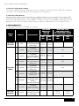
C. RAID Configurations
PowerEdge R710 Factory Configuration Summary
config
type
SAS/SATA
(No RAID)
SAS/SATA
(RAID)
SAS/SATA
(No RAID)
configs
description
non-mixed
drives, all
sata or
all sas
Min
HDD
Max
HDD
Mixed SAS/ SATA
Min 2xSAS+1xSATA
2.5": Max 2xSAS + 6xSATA
3.5": Max 2xSAS + 6xSATA
Min
HDD
MAX
HDD
0
MSS
Integrated
SAS/SATA No RAID
(SAS 6/iR)
2.5"=1
3.5"=1
2.5"=8
3.5"=8
1
MSSR0
Integrated
SAS/SATA RAID 0
(SAS 6/iR, PERC6/I)
2.5"=1*
3.5"=1*
2.5"=8
3.5"=8
N/A
2
MSSR1
Integrated
SAS/SATA RAID 1
(SAS 6/iR, PERC6/I)
2.5"=2
3.5"=2
2.5"=2
3.5"=2
N/A
3
MSSR5
Integrated
SAS/SATA RAID 5
(PERC 6/i)
2.5"=3
3.5"=3
2.5"=8
3.5"=8
N/A
4
MSSR6
Integrated
SAS/SATA RAID 6
(PERC 6/i)
2.5"=4
3.5"=4
2.5"=8
3.5"=8
N/A
5
MSSR10
Integrated
SAS/SATA RAID 10
(PERC 6/i)
2.5"=4
3.5"=4
2.5"=8
3.5"=8
6
MSSR1R1
Integrated
2.5"=2+2 2.5"=2+2
SAS/SATA RAID
3.5"=2+2 3.5"=2+2
1/RAID 1
(SAS 6/iR, PERC 6/i)
7
MSSR1R5
Integrated
2.5"=2+3 2.5"=2+6
SAS/SATA RAID
3.5"=2+3 3.5"=2+6
1/RAID 5 (PERC 6/i)
8
MSS-X
Integrated
SAS/SATA No RAID
(SAS 6/iR)
2.5"=3
3.5"=3
2.5"=6
3.5"=6
38
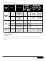
Dell™ PowerEdge™ R710 Technical Guidebook
config
type
configs
Min
HDD
9
SAS/SATA
(RAID)
config
type
SSD
(RAID)
SSD/SAS
(RAID)
description
non-mixed
drives, all
sata or
all sas
Integrated
SAS/SATA RAID
MSSR1R1- X
1/RAID 1
(SAS 6/iR, PERC 6/i)
configs
10 MSSR1R5-X
Integrated
description
SAS/SATA RAID
1/RAID 5
(PERC 6/i)
Max
HDD
non-mixed
drives, all SSD
Min
HDD
Max
HDD
Mixed SAS/ SATA
Min 2xSAS+1xSATA
2.5": Max 2xSAS + 6xSATA
3.5": Max 2xSAS + 6xSATA
Min
HDD
MAX
HDD
2.5"=2+2
2.5"=2+2
3.5"=2+2
3.5"=2+2
Mixed SSD/ SAs
Min 2xSSD+1xSAS
2.5": Max 2xSSD + 6xSAS
2.5"=2+3
2.5"=2+6
Min
MAX
3.5"=2+3
3.5"=2+6
HDD
HDD
11
MSSR1
Integrated SSD
RAID 1 (PERC 6/i)
2.5"=2
2.5"=2
3.5"=N/A 3.5"=N/A
N/A
12
MSSR5
Integrated SSD
RAID 5 (PERC 6/i)
2.5"=3
2.5"=
3.5"=N/A 3.5"=N/A
N/A
13
MSSR10
Integrated SSD
2.5"=4
2.5"=8
RAID 10 (PERC 6/i) 3.5"=N/A 3.5"=N/A
N/A
14
MSSR1R5-X
Integrated
SSD/SAS RAID
1/RAID 5
(PERC 6/i)
2.5"=2+3
3.5"=N/A
2.5"=2+6
3.5"=N/A
* Minimum of 1 hard drive for PERC6i ; and minimum of 2 for SAS6iR.
D. Storage Controllers
I. SAS 6/iR
The PowerEdge R710 internal SAS 6/iR HBA is an expansion card that plugs into a dedicated PCI
Express x8 slot (only four lanes wired). It incorporates two four-channel SAS IOCs for connection to
SAS/SATA hard disk drives. It is designed in a form factor that allows the same card to be used in R610
and T610.
39
Dell™ PowerEdge™ R710 Technical Guidebook
II. PERC 6i
For customers who want a hardware RAID solution, the PERC 6i is an option. The PERC 6i uses the LSI
1078 ROC (RAID on Chip) processor with a PCI Express host interface and DDR2 memory. A battery is
also available for backup.
LSI 2032 SCSI
ICH9
SAS HBA SAS/SATA
PERC SAS/SATA
product
Usage
R710
Support
Slot
PCIe
CON
PCIe
bracket
I/O
CON
RAID
x4 int
x4 int
0, 1,
5, 6,
10, 50,
and
60
Yes
TBBU
BBU
PERC 6/i
Integrated
Internal
Backplane
Storage
(HDD, SSD)
Yes, Max 1
PERC 6/E
Adapter
External
SAS/SATA
Storage
Yes, Max 2
(MD1000
Pompano
& MD1020
Ridgeback)
PCIe
slot
x8
Yes
x4 ext
x4 ext
0, 1,
5, 6,
10, 50,
and
60
PERC 5/E
Adapter
External
Legacy
Storage
Yes, Max 2
(MD1000,
Pompano,
& MD1020
Ridgeback)
PCIe
slot
x8
Yes
x4 ext
x4 ext
0, 1, 5,
10, 50
TBBU
SAS 6/iR
Integrated
Internal
Backplane
Storage
(No tape
or SSD
support)
Yes, Max 1
Storage
slot
x8
No
x4 int
x4 int
0, 1
No
SAS 5/E
Adapter
External
SAS (DAS,
Tape)
Yes, Max 2
PCIe
slot
x8
Yes
x4 ext
x4 ext
none
No
On Planar
via chipset
Internal
slim-line
SATA
Optical
and/or
TBU Only
(no HDD)
Yes, 2
ports for
Optical
and/or
TBU
n/a
n/a
n/a
x1 int
n/a
n/a
LSI 2032
Adapter
Internal or
External
SCSI
Tape/
Legacy
External
storage
Yes, Max 2
PCIe
slot
Yes
SCSI
int
SCSI
ext
n/a
n/a
Storage
slot
x8
x8
No
Note: A maximum of 2 external storage controllers (Dell PERC or SAS cards) are allowed in the system in
addition to the integrated storage controller.
40
Dell™ PowerEdge™ R710 Technical Guidebook
E. LED Indicators
Each disk drive carrier has two LED indicators visible from the front of the system. One is a green LED
for disk activity and the other is a bicolor (green/amber) LED for status information. The activity LED is
driven by the disk drive during normal operation. The bicolor LED is controlled by the SEP device on the
backplane. Both LEDs are used to indicate certain conditions under direction of a storage controller.
F. Optical Drives
Optical drives are optional in all of the PowerEdge R710 systems and connect to the planar via the SATA
interface. The following internal slim-line drives are available on the PowerEdge R710: DVD-ROM and
DVD+RW. PATA (IDE) optical drives are not supported.
If an optical drive is not ordered with the system, a blank is installed in its place.
G. Tape Drives
Internal tape drives are optional in systems with the 4x3.5" or 8x2.5" backplanes. Internal SATA tape
drives connect directly to the SATA connector on the planar. Internal SCSI tape drives connect through
the LSI 2032 PCI Express SCSI adapter card.
TAPE DRIVES
Internal Tape
Internal Tape
Drive Bays
Internal (RD1000 Half-Height SATA)
DAT72 Half –Height SCSI
One 3.5" Half-Height Tape Drive Bay
External (RD1000 USB)
LTO-2L (Legacy, SCSI)
LTO-3-060 (SCSI)
External TBU
LTO-3 (Legacy, SCSI)
LTO-4-120 (Half-Height SAS)
LTO-4-120 (Full-Height SAS)
2U external TBU (PV114T)
DAT72 Half–Height SCSI
4U SAS, SCSI, iSCSI, and FC
External
TBU/Automation
2U SAS, SCSI, iSCSI, and FC
ML6000 Family SAS, SCSI, and FC
2U external TBU (PV124T ) Legacy SCSI
41
Dell™ PowerEdge™ R710 Technical Guidebook
chassis config
tape backup unit (internal)
Backplane Type
Config
3.5" x 6"
3.5" x 4"
2.5" x 8
TBU Controller
TBU Cable
No TBU
N/A
N/A
No TBU
N/A
N/A
Internal for 3.5 Bay (RD 1000 Half-Height
SATA)
Connects to MB
XR724
DAT72 for 3.5 Bay (Half-Height SCSI)
LSI 2032 (SCSI) HBA
DR017
No TBU
N/A
N/A
Internal for 3.5 Bay (RD 1000
Half-Height SATA)
Connects to MB
RN694
DAT72 for 3.5 Bay (Half-Height SCSI)
LSI 2032 (SCSI) HBA
CJ176
Section 13. Video
A. Overview / Description
The PowerEdge R710 Integrated Dell Remote Access Controller 6 (iDRAC6) incorporates an integrated
video subsystem, connected to the 32-bit PCI interface of the ICH9. This logic is based on the Matrox
G200. The device only supports 2D graphics. The video device outputs are multiplexed between the
front and rear video ports. If a monitor is connected to the front video connector, it will take precedence
over the rear connection, thereby removing the display from the rear connection. The integrated video
core shares its video memory with the iDRAC6’s 128MB DDR2 application space memory. This memory
is also used for the KVM buffer.
The PowerEdge R710 system supports the following 2D graphics video modes:
resolution
refresh rate (Hz)
Color Depth (bit)
640 x 480
60, 72, 75, and 85
8, 16, and 32
800 x 600
56, 60, 72, 75, and 85
8, 16, and 32
1024 x 768
60, 72, 75, and 85
8, 16, and 32
1152 x 864
75
8, 16, and 32
1280 1024
60, 75, and 85
8 and 16
1280 1024
60
32
42
Dell™ PowerEdge™ R710 Technical Guidebook
Section 14. Audio
A. Overview / Description
No speakers supported
Section 15. Rack Information
A. Overview / Description
Rack installation components such as rails are provided with the PowerEdge R710 Rack Kit. The rack
installation components are as follows: Sliding Rack mount with latest generation Cable Management
Arm (CMA). When the system is installed in a rack, please observe the following guidelines:
Nothing should be located within 12" of the front of the unit that would restrict the airflow into the system.
Nothing should be mounted or placed behind the chassis that would restrict airflow from exiting the
system. Only Dell approved CMAs can be placed behind the chassis. All other objects should be located
at least 24" away from the rear of the chassis.
When two systems are placed back to back, the separation between the units should be at least 24" if
the exit airflow is equivalent for the two chassis. This allows the exit air to escape without creating an
extreme back pressure at the rear of one of the chassis.
B. Cable Management Arm (CMA)
Cable Type
Number of cables
Mouse – USB
1
Keyboard – USB
1
Video – VGA
1
Power Cords
2
LOMs – Ethernet
1
PCI NICs
1
Total
8
Notes: • CMA supports for the maximum number of cables supported by system
• The numbers in this matrix represent the number and types of external cables required to be
supported by the CMA solution.
• This matrix is built on the practical worst case configuration in each platform based on prior
and projected take rates. Note that other combinations of adapters and associated cables exist,
but are assumed to fall within these guidelines from the standpoint of bend radius and
flexibility, cable bundling, cable volume, etc.
• PCI NIC cables are assumed to be Ethernet.
• KVM cable dongle may be used for mouse/keyboard/video.
43
Dell™ PowerEdge™ R710 Technical Guidebook
C. Rails
Support
Support
Support
Support
for
for
for
for
tool-less installation in CEA-310-E compliant square hole 4-post racks including:
Dell 2410 24U Rack
Dell 4210 Rack
HP/Compaq 10xxx series
Support for tooled or tool-less installation in CEA-310-E compliant round hole 4-post racks
(tool-less preferred)
Support for flush and center mount installation in CEA-310-E compliant 2-post racks (1U & 2U only)
The R710 rail supports the following racks:
Support for Dell 4210 & 2410 racks
Support for Dell 4200 & 2400 racks without CMA
Support for HP/Compaq 10XXX series racks
Support for HP/Compaq 9XXX & 7XXX series racks without CMA
44
Dell™ PowerEdge™ R710 Technical Guidebook
Section 16. Operating Systems
A. Overview / Description
The PowerEdge R710 supports Windows®, Linux®, and Solaris™ Operating Systems.
Windows® Support:
x86
or
x64
INSTALLATION
Factory
INSTALLATION
logo
certification
Test/
Validate
support
Shipping
Yes
Yes
Yes
Windows
Hardware
Quality Labs Windows 2008
Shipping
Yes
Yes
Yes
Windows
Hardware
Quality Labs Windows 2008
Shipping
Yes
Yes
Yes
Windows
Hardware
Quality Labs Windows 2008
Shipping
Yes
Yes
Yes
Windows
Hardware
Quality Labs Windows 2008
Available in
August October
2009
Yes
Yes
Yes
Windows
Hardware
Quality Labs Windows 2008
Available in
August October
2009
Yes
Yes
Windows
Hardware
Quality Labs Windows 2008
Available in
August October
2009
Yes
Yes
schedule
Windows® Small Business Server 2008 and Essential Business Server 2008
x64
Standard/
Premium
Yes
Windows
Hardware
Quality Labs Windows 2008
Windows Server® 2008 (x64 includes Hyper-V™)
Standard
x64
Enterprise
Datacenter
Windows Server® 2008
Standard
x86
Enterprise
Windows® Web Server 2008
x86
and
x64
Web
Windows Server® 2008, SP2 (x64 includes Hyper-V™)
Standard
x64
Enterprise
Datacenter
Windows Server® 2008, SP2
Standard
x86
Enterprise
Windows® Web Server 2008, SP2
x86
and
x64
Web
Yes
45
Dell™ PowerEdge™ R710 Technical Guidebook
x86
or
x64
INSTALLATION
Factory
INSTALLATION
logo
certification
schedule
Test/
Validate
support
Yes
Windows
Hardware
Quality Labs Windows 2008
Release 2
Available in
November
2009 January
2010
Yes
Yes
Available in
June 2009
n/A
Available in
June 2009
Yes
Yes
Yes
n/A
Shipping
Yes
Yes
Available in
June 2009
n/A
Available in
June 2009
Yes
Yes
n/A
Shipping
Yes
Yes
Available in
June 2009
n/A
Available in
June 2009
Yes
Yes
Drop in the box
n/A
Available in
June 2009
Yes
Yes
Windows Server® 2008, R2, (x64 includes Hyper-V™)
Standard
x64
Enterprise
Datacenter
Linux support:
Red Hat® Enterprise Linux 4.7
x86
and
x64
ES/AS
Red Hat Enterprise Linux 5.2
x86
and
x64
Standard/AP
Red Hat Enterprise Linux 5.3
x86
and
x64
Standard/AP
Novell® SUSE® Linux Enterprise Server 10 SP2
x64
Enterprise
Yes
Novell SUSE Linux Enterprise Server 11
x64
Enterprise
Solaris™ 10 05/09
x64
Enterprise
46
Dell™ PowerEdge™ R710 Technical Guidebook
Section 17. Virtualization
A. Overview / Description
Supported embedded hypervisors:
• Microsoft® Windows Server® 2008 Hyper-V
• VMware® ESXi Version 4.0 and 3.5 update 4
• Citrix® XenServer 5.0 with Hotfix 1 or later
Section 18. Systems Management
A. Overview / Description
Dell is focused on delivering open, flexible, and integrated solutions the help our customers reduce the
complexity of managing disparate IT assets. We build comprehensive IT management solutions.
Combining Dell PowerEdge Servers with a wide selection of Dell-developed management solutions, we
provide customers choice and flexibility – so you can simplify and save in environments of any size.
To help you meet your server performance demands, Dell offers Dell OpenManage™ systems
management solutions for:
• Deployment of one or many servers from a single console
• Monitoring of server and storage health and maintenance
• Update of system, operating system, and application software
We offer IT management solutions for organizations of all sizes – priced right, sized right, and
supported right.
B. Server Management
A Dell Systems Management and Documentation DVD and a Dell Management Console DVD are included
with the product. ISO images are also available. The following sections briefly describe the content.
Dell Systems Build and Update Utility: Dell Systems Build and Update Utility assists in OS install and
pre-OS hardware configuration and updates.
OpenManage Server Administrator: The OpenManage Server Administrator (OMSA) tool provides a
comprehensive, one-to-one systems management solution, designed for system administrators to
manage systems locally and remotely on a network. OMSA allows system administrators to focus on
managing their entire network by providing comprehensive one-to-one systems management.
Management Console: Our legacy IT Assistant console is also included, as well as tools to allow access
to our remote management products. These tools include: Remote Access Service, for iDRAC, and the
BMC Management Utility.
Active Directory Snap-in Utility: The Active Directory Snap-in Utility provides an extension snap-in to
the Microsoft Active Directory. This allows you to manage Dell specific Active Directory objects. The
Dell-specific schema class definitions and their installation are also included on the DVD.
Dell Systems Service Diagnostics Tools: Dell Systems Service and Diagnostics tools deliver the latest
Dell optimized drivers, utilities, and operating system-based diagnostics that you can use to update
your system.
eDocs: The section includes Acrobat files for PowerEdge systems, storage peripheral and
OpenManage software.
47
Dell™ PowerEdge™ R710 Technical Guidebook
Dell Management Console DVD: The Dell Management Console is a Web-based systems management
software that enables you to discover and inventory devices on your network. It also provides advanced
functions, such as health and performance monitoring of networked devices and patch management
capabilities for Dell systems.
Server Update Utility: In addition to the Systems Management Tools and Documentation and Dell
Management Console DVDs, customers have the option to obtain Server Update Utility DVD. This
DVD has an inventory tool for managing updates to firmware, BIOS and drivers for either Linux or
Windows varieties.
C. Embedded Server Management
The PowerEdge R710 implements circuitry for the next generation of Embedded Server Management. It
is Intelligent Platform Management Interface (IPMI) v2.0 compliant. The iDRAC6 (Integrated Dell Remote
Access Controller) is responsible for acting as an interface between the host system and its management
software and the periphery devices. These periphery devices consist of the PSUs, the storage backplane,
integrated SAS HBA or PERC 6/i and control panel with semi-intelligent display.
The iDRAC6 provides features for managing the server remotely or in data center lights-out
environments.
Advanced iDRAC features require the installation of the iDRAC6 Enterprise card.
I. Unmanaged Persistent Storage
The unmanaged persistent storage consists of two ports:
• one located on the control panel board
• one located on the Internal SD Module
The port on the control panel is for an optional USB key and is located inside the chassis. Some of the
possible applications of the USB key are:
• User custom boot and pre-boot OS for ease of deployment or diskless environments
• USB license keys for software applications like eToken™ or Sentinel Hardware Keys
• Storage of custom logs or scratch pad for portable user-defined information (not hot-pluggable)
The Internal SD Module is dedicated for an SD Flash Card with embedded Hypervisor for virtualization.
The SD Flash Card contains a bootable OS image for virtualized platforms.
II. Lifecycle Controller/Unified Server Configurator
Embedded management is comprised of several pieces which are very interdependent.
• Lifecycle Controller
• Unified Server Configurator
• iDRAC6
• vFLASH
Lifecycle controller is the hardware component that powers the embedded management features. It is
integrated and tamperproof storage for system-management tools and enablement utilities (firmware,
drivers, etc.). It is flash partitioned to support multiple, future use cases.
Dell Unified Server Configurator is a 1:1 user interface exposing utilities from Lifecycle Controller. Customers
will use this interface to configure hardware, update server, run diagnostics, or deploy the operating
system. This utility resides on Lifecycle Controller. To access the Unified Server Configurator, press <F10>
key within 10 seconds of the Dell logo display during the system boot process. Current functionality
enabled by the Unified Server Configurator includes:
48
Dell™ PowerEdge™ R710 Technical Guidebook
feature
description
Faster O/S
Installation
Drivers and the installation utility are embedded on system, so no need to
scour DELL.COM
Faster System Updates
Integration with Dell support automatically directed to latest versions
of the Unified Server Configurator iDRAC, RAID, BIOS, NIC, and
Power Supply
Update Rollback
Description: Ability to recover to previous “known good state” for all
updatable components
More Comprehensive
Diagnostics
Diagnostic utilities are embedded on system
Simplified Hardware
Configuration
Detects RAID controller and allows user to configure virtual disk
and choose virtual disk as boot device, eliminating the need to
launch a separate utility and also provides configuration for iDRAC,
BIOS, and NIC/LOM.
III. iDRAC6 Express
The iDRAC6 Express is the first tier of iDRAC6 upgrades. In addition to upgrading the system with a
Lifecycle Controller, the iDRAC6 Express offers the following key features:
• Graphical web interface
• Standard-based interfaces
• Server Sensor monitoring and fault alerting
• Secure operation of remote access functions including authentication, authorization,
and encryption
• Power control and management with the ability to limit server power consumption and
remotely control server power states
• Advanced troubleshooting capabilities
For more information on iDRAC6 Express features see the table below.
IV. iDRAC6 Enterprise
The optional iDRAC6 Enterprise card provides access to advanced iDRAC6 features. The iDRAC6
Enterprise connects directly to the PowerEdge R710 planar and is mounted parallel to the planar
with stand-offs.
Key features for the iDRAC6 Enterprise include:
• Scripting capability with Dell’s Racadm command-line
• Remote video, keyboard, and mouse control with Virtual Console
• Remote media access with Virtual Media
• Dedicated network interface
Additionally, the iDRAC6 Enterprise can be upgraded by adding the vFlash Media card. This is a 1GB
Dell branded SD card that enabled a persistent 256MB virtual flash partition. In the future, vFlash will be
expanded to include additional features.
49
Dell™ PowerEdge™ R710 Technical Guidebook
A more detailed feature list for iDRAC6 Enterprise and vFlash is included in the table below.
BMC
iDRAC6
Express
iDRAC6
Enterprise
VFlash
Media
4
4
4
4
Web-based GUI
4
4
4
SNMP
4
4
4
WSMAN
4
4
4
SMASH-CLP
4
4
4
4
4
Feature
Interface and Standards Support
IPMI 2.0
Racadm command-line
Conductivity
Shared/Failover Network Modes
4
4
4
4
IPv4
4
4
4
4
VLAN tagging
4
4
4
4
IPv6
4
4
4
Dynamic DNS
4
4
4
4
4
Dedicated NIC
Security & Authentication
Role-based Authority
4
4
4
4
Local Users
4
4
4
4
Active Directory
4
4
4
SSL Encryption
4
4
4
Remote Management & Remediation
Remote Firmware Update
4
4
4
4
Server power control
4
4
4
4
Serial-over-LAN (with proxy)
4
4
4
4
Serial-over-LAN (no proxy)
4
4
4
Power capping
4
4
4
Last crash screen capture
4
4
4
Boot capture
4
4
4
Serial-over-LAN
4
4
4
Virtual media
4
4
Virtual console
4
4
50
Dell™ PowerEdge™ R710 Technical Guidebook
Feature
BMC
iDRAC6
Express
Virtual console sharing
iDRAC6
Enterprise
VFlash
Media
4
4
Virtual flash
4
Monitoring
Sensor Monitoring and Alerting
4
4
4
4
Real-time Power Monitoring
4
4
4
Real-time Power Graphing
4
4
4
Historical Power Counters
4
4
4
4
4
4
RAC Log
4
4
4
Trace Log
4
4
4
Logging Features
System Event Log
4
51
Dell™ PowerEdge™ R710 Technical Guidebook
Section 19. Peripherals
A. USB peripherals
The PowerEdge R710 supports the following USB devices:
• DVD (bootable; requires two USB ports)
• USB Key (bootable)
• Keyboard (only one USB keyboard is supported)
• Mouse (only one USB mouse is supported)
B. External Storage
external storage
EMC's AX Arrays (SCSI, FC, and iSCSI)
SAN Support
EMC's CX Arrays (SCSI, FC, and iSCSI)
EqualLogic's PS5XXX Arrays (iSCSI)
OMSS X.X for MD1000
SAS Management
SW for xBOD
OMSS X.X for MD1020
X.X for MD3000
for MD3000i
Attachment to PV NX1950 including iSCSI and clustering support
PV NAS
Attachment to Win Storage Server on PE
Attachment to EMC NS500G (S&P)
MD1000 JBOD
PV DAS
MD3000 RBOD
MD1120 2.5 SAS/SATA JBOD
MD1100 3.5 SAS/SATA JBOD
PV SAN
EqualLogic™
SAS xBOD SW
MD3000i iSCSI RAID array
PS5000 family
PS5500 family
OpenManage Storage Manager
52
Dell™ PowerEdge™ R710 Technical Guidebook
Section 20. Documentation
A. Overview, Description, and List
PowerEdge R710 and other 11G systems use the new enterprise documentation set. The following is a
summary of some of the documents slated for the PowerEdge R710 product. For the complete list of
documents, including language requirements and delivery scheduling, refer to the Documentation Matrix
and the Documentation Milestones in the InfoDev Functional Publications Plan.
• Getting Started Guide: This guide provides initial setup steps, a list of key system features, and
technical specifications. This document is required for certain worldwide regulatory submittals.
This guide is printed and shipped with the system, and is also available in PDF format on the
Dell support site.
• Hardware Owner’s Manual: This document provides troubleshooting and remove/replace
procedures, as well as information on the System Setup program, system messages, codes,
and indicators. This document is provided to customers in HTML and PDF format at the Dell
support site.
• System Information Label: The system information label documents the system board layout
and system jumper settings and is located on the system cover. Text is minimized due to space
limitations and translation considerations. The label size is standardized across platforms.
• Information Update: This is a PDF document that provides information on late changes and
issues having significant customer impact which were discovered after document signoff.
• General System Information Placemat: This is a paper document that is provided with every
system. The document provides general information about the system, including software
license agreement information and the location of the service tag.
• Rack Placemat: This is a paper document that is provided with the rack kits. The document
provides an overview of procedures for setting up the rack.
Section 21. PAckaging options
Packaging
Provide packaging to support system
Packaging should
incorporate keyboard,
mouse, bezel, Doc,
CDs, rails
•W
ill not bag the server in outbound pack
• Multi-pack rails targeted to go in a box within the
multi-pack but investigation underway for a separate
box for ease of customer staging
• Accessory tray needs a cover and icon showing contents
• Doc Box – separate box within the main box containing
import documentation and software (OS, OM, etc.)
53
Dell™ PowerEdge™ R710 Technical Guidebook
Appendix
R710 Volatility Chart.
NonVolatile
RAM
volatile
ram
Reference
designator
QTY
Size
Type [e.g., Flash PROM,
EEPROM]:
1
2
1
1
1
1
1
4MB
Flash EEPROM (SPI interface)
512KB
FLASH (NOR)
4KB
ROM
8KB
RAM
1200 Macro cells
Internal Flash EEPROM
1KB
RAM
1GB
NAND FLASH
up to 18 DIMMs
*16GB
RAM
Planar, Poweredge R710
System BIOS SPI Flash
LOM Configuration Data
iDRAC6 Controller ROM
iDRAC6 Controller RAM
System CPLD
System CPLD
iDRAC6 Express Internal Flash
Y
Y
Y
Y
Y
Y
Y
System RAM
TPM ID EEPROM
(Plug in module only)
TPM Binding EEPROM
(on China planar only)
Y
U_SPI_BIOS
U15, U16
U_IBMC
U_IBMC
U_CPLD
U_CPLD
U_EMMC
J_CPU(2:1)_
CH(2:0)_
DIMM(3:1)
18
Y
U_SEEPROM
1
256B
EEPROM
Y
U7261
1
256B
EEPROM
1
128MB
DDR2 RAM
1
4KB
EEPROM
1
1
2MB
FLASH (NOR)
128 bytes
EEPROM
U_ICH9
1
256KB
Battery backed RAM
U_SEP
1
32KB
Embedded Microcontroller
Flash
1
User selectable
License key hard set ROM or
user choice
1
User selectable 1GB shipped
Secure Digital NAND Flash
Up
to 2
Maximum
supported = 2MB
per PSU
Embedded microcontroller
flash
iDRAC6 SDRAM
Y
iDRAC6 FRU
Y
iDRAC6 Boot Block Flash
Trusted Platform Module
Y
Y
N
U_IBMC_
MEM
U_IBMC_
FRU
U_IBMC_SPI
U_TPM
chipset
CMOS
Y
2.5" backplane or 3.5" Backplane
Storage Controller Processor
Y
control panel
Internal USB
Y
Internal SD Module
Y
J_USBKEY
(connector)
J_SDCARD
(Connector)
Power Supply
PSU Microcontroller
Varies by
part number
Y
PERC 6/i Integrated
PERC NVSRAM Config Data
PERC Firmware
Y
Y
1
1
1
1
1
1
32KB
Non-volatile SRAM
4MB
FLASH (NOR)
256MB
RAM
Y
Y
Y
U23
U24
U58-61
U40
U21
U_CPLD
256MB
EEPROM
1KB
EEPROM
72 macrocells
Internal Flash EEPROM
Y
Y
Y
U3
U4
U1
1
1
1
4MB
FLASH (NOR)
256KB
EEPROM
32KB
Non-volatile SRAM
Y
J_SD
(connector)
1
1GB @ RTS,
Larger later
Secure Digital NAND Flash
Y
PERC Cache RAM
FRU
IBUTTON Key EEPROM
CPLD
SAS 6/iR Integrated
Controller Configuration Data
FRU
Integrated Mirroring NVSRAM
iDRAC6 Enterprise
VFlash
54
Dell™ PowerEdge™ R710 Technical Guidebook
R710 Volatility Chart Continued.
Can user programs or operating
system write data to it during
normal operation?
Purpose? [e.g., boot code]
Planar, Poweredge R710
System RAM
TPM ID EEPROM
(Plug in module only)
TPM Binding EEPROM
(on China planar only)
iDRAC6 SDRAM
iDRAC6 FRU
Yes
Boot Code, System Configuration Information, EUFI
environment
LAN on motherboard configuration and firmware
not utilized
iDRAC internal RAM
System-specific hardware logic
not utilized
iDRAC Operating System plus Managed System Services
Repository (i.e., Unified Server Configurator, OS drivers,
diagnostics, rollback versions of various programmables)
System OS RAM
No
BIOS Identification of TPM module
No
BIOS binding of plug in module to a particulare planar
No
No
iDRAC6 Boot Block Flash
No
Trusted Platform Module
yes
BMC OS + VGA frame buffer
Motherboard electronic product identifier
iDRAC boot loader and configuration (i.e., MAC address),
life cycle log, and system event log
Storage of encryption keys
No
BIOS settings
System BIOS SPI Flash
No
LOM Configuration Data
iDRAC6 Controller ROM
iDRAC6 Controller RAM
System CPLD
System CPLD
No
No
No
No
No
iDRAC6 Express Internal Flash
No for iDRAC Operating System. Yes for
Managed System Services Repository
chipset
CMOS
2.5" backplane or 3.5" Backplane
Storage Controller Processor
No
Backplane firmware (HDD status, etc.)
control panel
Internal USB
Yes as allowed by OS
Internal SD Module
Yes as allowed by OS
Normal usage is read only software license key, but not
limited
Normal usage is embedded hypervisor OS but not
limited
Power Supply
PSU Microcontroller
No
Power supply operation, power telemetry data, and fault
behaviors
PERC 6/i Integrated
PERC NVSRAM Config Data
PERC Firmware
PERC Cache RAM
No
No
No - not directly.
FRU
No
IBUTTON Key EEPROM
CPLD
No
No
SAS 6/iR Integrated
Controller Configuration Data
No
FRU
No
Integrated Mirroring NVSRAM
iDRAC6 Enterprise
No
VFlash
Yes - When enabled, installed, and the media
does not have the write protect switch applied
Stores configuration data of HDDs
Storage Controller Firmware
Storage RAID controller cache
Card product identification for system inventory
purposes
Feature enablement encyrpted key
HW control logic (i.e., power sequencing)
Stores configuration data of HDDs
Card product identification for system inventory
purposes
Stores configuration data of HDDs
Storage of logs, user images like files, drivers, OS's, etc.
55
Dell™ PowerEdge™ R710 Technical Guidebook
R710 Volatility Chart Continued.
How is data input to this memory?
Planar, Poweredge R710
System BIOS SPI Flash
LOM Configuration Data
iDRAC6 Controller ROM
iDRAC6 Controller RAM
System CPLD
System CPLD
iDRAC6 Express Internal
Flash
System RAM
TPM ID EEPROM
(Plug in module only)
TPM Binding EEPROM
(on China planar only)
iDRAC6 SDRAM
iDRAC6 FRU
iDRAC6 Boot Block
Flash
Trusted Platform Module
Loading flash memory requires a vendor-provided firmware file and loader program that is executed by booting
up the system from a floppy or OS-based executable containing the firmware file and the loader. System
loaded with arbitrary data in firmware memory would not operate. Future firmware releases may add support
for recovery of a bad/corrupted BIOS ROM image via the iDRAC (administrator privilege plus specific firmware,
binary, and commands)
Loading flash memory requires a vendor-provided firmware file and loader program that is executed by booting
up the system from a floppy or OS-based executable containing the firmware file and the loader. LOMs loaded
with arbitrary data in firmware memory would not operate.
N/A
iDRAC embedded system
Loading flash memory requires a vendor-provided firmware file and loader program that is executed by booting
up the system from a floppy or OS-based executable (currently only DRMK utility support) containing the
firmware file and the loader. System loaded with arbitrary data in CPLD memory would not operate.
Not utilized
iDRAC OS: Loading flash memory requires a vendor-provided firmware file and loader program that is executed
by booting up the system from a floppy or OS-based executable containing the firmware file and the loader.
System loaded without a good iDRAC firmware image yields a non-functional iDRAC. Managed Services
Repository: Various partitions are loaded via vendor-provided firmware file and loader program just like iDRAC
OS.
System OS
Factory load only.
BIOS only
Embedded iDRAC OS for 108MB and 8MB for VGA frame buffer
Factory and iDRAC embedded OS
Loading flash memory requires a vendor-provided firmware file and loader program that is executed by booting
up the system from a floppy or OS-based executable or out-of-band firmware updates across the management
network. Bad contents yield the iDRAC inoperable and unrecoverable in the customer environment. Note the
life cycle log is automatically updated by the iDRAC as various system component FW, HW, and SW verions are
changed.
Using TPM-enabled operating systems
chipset
CMOS
BIOS control only via input such as BIOS F2 menu user configuration settings (such as boot order)
2.5" backplane or 3.5" Backplane
Storage Controller Processor
Loading flash memory requires a vendor-provided firmware file and loader program that is executed by booting
up the system from a floppy or OS-based executable (DRMK, USC, OS DUPs utility support) containing the firmware file and the loader. Backplane loaded with bad firmware will not provide backplane and HDD status.
control panel
Internal USB
Internal SD Module
Either read-only license key or OS control copies
Factory load, OS run time usage, and OS updates and configuration changes.
Power Supply
PSU Microcontroller
Loading flash memory requires a vendor-provided firmware file and loader program that is executed by booting
up the system from a floppy or OS-based executable (Unified Server Configurator) containing the firmware file
and the loader. PSUs loaded with bad firmware will not provide PSU functional behavior and result in PSU system
faults.
PERC 6/i Integrated
PERC NVSRAM Config
Data
PERC Firmware
PERC Cache RAM
FRU
IBUTTON Key EEPROM
CPLD
Embedded storage firmware controls this data
Loading flash memory requires a vendor-provided firmware file and loader program that is executed by booting
up the system from a floppy or OS-based executable (DUPs, Unified Server Configurator) containing the firmware
file and the loader. Storage adapters loaded with bad firmware will not provide storage controller behavior.
Embedded storage firmware controls the use of storage cache data.
Factory only. Not customer updatable.
Factory only. Not customer updatable.
Factory only. Not customer updatable.
SAS 6/iR Integrated
56
Dell™ PowerEdge™ R710 Technical Guidebook
R710 Volatility Chart Continued.
How is data input to this memory?
Planar, Poweredge R710
Controller Configuration
Data
FRU
Integrated Mirroring
NVSRAM
iDRAC6 Enterprise
VFlash
Loading flash memory requires a vendor-provided firmware file and loader program that is executed by booting
up the system from a floppy or OS-based executable (DUPs, Unified Server Configurator) containing the firmware
file and the loader. Storage adapters loaded with bad firmware will not provide storage controller behavior.
Factory only. Not customer updatable.
Embedded storage firmware controls this data
Preloaded media before installation, or remote out-of-band upload of user data (i.e., ISO images, files) or local
server read/write capability to use like a hard disk
How is this memory write protected?
How is the memory cleared?
Planar, Poweredge R710
System BIOS SPI Flash
Software write protected
iDRAC6 Controller ROM
iDRAC6 Controller RAM
Not explicitly protected but special applications
are needed to communicate through the LOMs to
reprogram this ROM.
Protected permanently by hardware
n/a
System CPLD
Requires special system-specific utility
System CPLD
It's not accessible
Writes are proxied through a temporary iDRAC
scratchpad RAM and not directly made from an OS or
OS application.
OS control
LOM Configuration Data
iDRAC6 Express Internal
Flash
System RAM
TPM ID EEPROM
(Plug in module only)
TPM Binding EEPROM
(on China planar only)
HW read only
Locked by BIOS from physical access by anyone after
boot
iDRAC6 SDRAM
n/a
iDRAC6 FRU
Writes controlled by iDRAC embedded OS
iDRAC6 Boot Block
Flash
iDRAC embedded OS control of the write protection.
Trusted Platform Module
SW write protected
Not possible with any utilities or applications and
system is not functional if corrupted/removed.
Not user clearable
Not clearable
iDRAC reset
Not possible with any utilities or applications and
system is not functional if corrupted/removed.
Not clearable
Not user clearable
Reboot or power down system
Not - read only
N/A - BIOS control only
AC cycle for BMC OS and reset / power off server for
VGA frame buffer
EPPID is not clearable
Not possible with any utilities or applications and
iDRAC does not function as expected if corrupted/
removed. Lifecycle log is clearable only in a factory
environment. SEL is user clearable.
F2 setup option
chipset
CMOS
N/A - BIOS only control
Planar NVRAM_CLR jumper or remove AC cord, remove
cover, remove coin cell battery. Wait for 30 seconds,
replace battery, cover, and then AC cord.
F2 system setup option to restore defaults
2.5" backplane or 3.5" Backplane
Storage Controller
Processor
Embedded firmware only writeable through controlled
iDRAC methods
Not possible with any utilities or applications and
backplane does not function as expected if corrupted/
removed.
OS control
Only by SD card write-protect switch.
OS control format
OS control format
Protected by the embedded microcontroller. Special
keys are used by special vendor-provided utilities to
unlock the ROM with various CRC checks during load.
N/A - not in-system clearable
control panel
Internal USB
Internal SD Module
Power Supply
PSU Microcontroller
57
Dell™ PowerEdge™ R710 Technical Guidebook
R710 Volatility Chart Continued.
How is this memory write protected?
How is the memory cleared?
Planar, Poweredge R710
PERC 6/i Integrated
PERC NVSRAM Config
Data
PERC Firmware
Storage controller firmware accessed only
N/A - not in-system clearable
Write control access by storage controller firmware
PERC Cache RAM
Storage controller firmware accessed only
N/A - not in-system clearable
Storage controller firmware clearable only. Remove AC
AND deplete or remove backup battery.
FRU
IBUTTON Key EEPROM
CPLD
SAS 6/iR Integrated
Controller Configuration
Data
FRU
Integrated Mirroring
NVSRAM
iDRAC6 Enterprise
VFlash
Protected in that no iDRAC-embedded firmware writes
to this device. Although very convoluted, theoretically,
IPMI I2C Master write commands would flow through to
overwrite this EEPROM
SHA1 encryption included. Storage controller use only
Only factory programmable
N/A - not in-system clearable
N/A - not in-system clearable
Write control access by storage controller firmware
N/A - not in-system clearable
Protected in that no iDRAC-embedded firmware writes
to this device. Although very convoluted, theoretically,
IPMI I2C Master write commands would flow through to
overwrite this EEPROM
N/A - not in-system clearable
Storage controller firmware accessed only
N/A - not in-system clearable
Media write protection switch or OS control
iDRAC-based format or local OS format or delete or
card removal and formatted on a client
N/A - not in-system clearable
58