1
Technical Information
Motorola G24 Developer’s Guide
AT Commands Reference Manual
AUGUST 5, 2008
6889192V28-K
SPECIFICATIONS SUBJECT TO CHANGE WITHOUT NOTICE
Notice
While reasonable efforts have been made to assure the accuracy of this document, Motorola, Inc. assumes no liability resulting
from any inaccuracies or omissions in this document, or from use of the information obtained herein. The information in this
document has been carefully checked and is believed to be entirely reliable. However, no responsibility is assumed for
inaccuracies or omissions. Motorola, Inc. reserves the right to make changes to any products described herein and reserves the
right to revise this document and to make changes from time to time in content hereof with no obligation to notify any person of
revisions or changes. Motorola, Inc. does not assume any liability arising out of the application or use of any product, software, or
circuit described herein; neither does it convey license under its patent rights or the rights of others.
It is possible that this publication may contain references to, or information about Motorola products (machines and programs),
programming, or services that are not announced in your country. Such references or information must not be construed to mean
that Motorola intends to announce such Motorola products, programming, or services in your country.
Copyrights
This instruction manual, and the Motorola products described in this instruction manual may be, include or describe copyrighted
Motorola material, such as computer programs stored in semiconductor memories or other media. Laws in the United States and
other countries preserve for Motorola and its licensors certain exclusive rights for copyrighted material, including the exclusive
right to copy, reproduce in any form, distribute and make derivative works of the copyrighted material. Accordingly, any
copyrighted material of Motorola and its licensors contained herein or in the Motorola products described in this instruction
manual may not be copied, reproduced, distributed, merged or modified in any manner without the express written permission of
Motorola. Furthermore, the purchase of Motorola products shall not be deemed to grant either directly or by implication, estoppel,
or otherwise, any license under the copyrights, patents or patent applications of Motorola, as arises by operation of law in the sale
of a product.
Computer Software Copyrights
The Motorola and 3rd Party supplied Software (SW) products described in this instruction manual may include copyrighted
Motorola and other 3rd Party supplied computer programs stored in semiconductor memories or other media. Laws in the United
States and other countries preserve for Motorola and other 3rd Party supplied SW certain exclusive rights for copyrighted
computer programs, including the exclusive right to copy or reproduce in any form the copyrighted computer program.
Accordingly, any copyrighted Motorola or other 3rd Party supplied SW computer programs contained in the Motorola products
described in this instruction manual may not be copied (reverse engineered) or reproduced in any manner without the express
written permission of Motorola or the 3rd Party SW supplier. Furthermore, the purchase of Motorola products shall not be deemed
to grant either directly or by implication, estoppel, or otherwise, any license under the copyrights, patents or patent applications of
Motorola or other 3rd Party supplied SW, except for the normal non-exclusive, royalty free license to use that arises by operation
of law in the sale of a product.
VENDOR COPYRIGHT
Apache Software Foundation - Copyright 2004-2005 All Rights Reserved
Usage and Disclosure Restrictions
License Agreements
The software described in this document is the property of Motorola, Inc. and its licensors. It is furnished by express license
agreement only and may be used only in accordance with the terms of such an agreement.
Copyrighted Materials
Software and documentation are copyrighted materials. Making unauthorized copies is prohibited by law. No part of the software
or documentation may be reproduced, transmitted, transcribed, stored in a retrieval system, or translated into any language or
computer language, in any form or by any means, without prior written permission of Motorola, Inc.
High Risk Materials
Components, units, or third-party products used in the product described herein are NOT fault-tolerant and are NOT designed,
manufactured, or intended for use as on-line control equipment in the following hazardous environments requiring fail-safe
controls: the operation of Nuclear Facilities, Aircraft Navigation or Aircraft Communication Systems, Air Traffic Control, Life
Support, or Weapons Systems (High Risk Activities"). Motorola and its supplier(s) specifically disclaim any expressed or implied
warranty of fitness for such High Risk Activities.
Trademarks
MOTOROLA and the Stylized M Logo are registered in the US Patent & Trademark Office. All other product or service names are
the property of their respective owners.
©Copyright 2008 Motorola, Inc.
Copyright, Trademarks and Disclaimer
REV052604
Table of Contents
Manual Scope . . . . . . . . . . . . . . . . . . . . . . . . . . . . . . . . . . . . . . . . . . . . . . . . . . . . . . . . . . . . . . . . . . .xxi
Target Audience . . . . . . . . . . . . . . . . . . . . . . . . . . . . . . . . . . . . . . . . . . . . . . . . . . . . . . . . . . . . . . . . .xxi
Manual Organization . . . . . . . . . . . . . . . . . . . . . . . . . . . . . . . . . . . . . . . . . . . . . . . . . . . . . . . . . . . . . .xxi
Applicable Documents . . . . . . . . . . . . . . . . . . . . . . . . . . . . . . . . . . . . . . . . . . . . . . . . . . . . . . . . . . . xxii
Contact Us . . . . . . . . . . . . . . . . . . . . . . . . . . . . . . . . . . . . . . . . . . . . . . . . . . . . . . . . . . . . . . . . . . . . . xxii
Text Conventions. . . . . . . . . . . . . . . . . . . . . . . . . . . . . . . . . . . . . . . . . . . . . . . . . . . . . . . . . . . . . . . . xxii
Manual Banner Definitions . . . . . . . . . . . . . . . . . . . . . . . . . . . . . . . . . . . . . . . . . . . . . . . . . . . . . . . xxiii
Field Service . . . . . . . . . . . . . . . . . . . . . . . . . . . . . . . . . . . . . . . . . . . . . . . . . . . . . . . . . . . . . . . . . . xxiii
General Safety . . . . . . . . . . . . . . . . . . . . . . . . . . . . . . . . . . . . . . . . . . . . . . . . . . . . . . . . . . . . . . . . . xxiii
Caring for the Environment. . . . . . . . . . . . . . . . . . . . . . . . . . . . . . . . . . . . . . . . . . . . . . . . . . . . . . . .xxiv
Limitation of Liability . . . . . . . . . . . . . . . . . . . . . . . . . . . . . . . . . . . . . . . . . . . . . . . . . . . . . . . . . . . . xxv
Warranty Notification . . . . . . . . . . . . . . . . . . . . . . . . . . . . . . . . . . . . . . . . . . . . . . . . . . . . . . . . . . . . xxv
How to Get Warranty Service? . . . . . . . . . . . . . . . . . . . . . . . . . . . . . . . . . . . . . . . . . . . . . . . . . . . . .xxvi
Claiming . . . . . . . . . . . . . . . . . . . . . . . . . . . . . . . . . . . . . . . . . . . . . . . . . . . . . . . . . . . . . . . . . . . . . .xxvi
Conditions . . . . . . . . . . . . . . . . . . . . . . . . . . . . . . . . . . . . . . . . . . . . . . . . . . . . . . . . . . . . . . . . . . . . xxvii
What is Not Covered by the Warranty . . . . . . . . . . . . . . . . . . . . . . . . . . . . . . . . . . . . . . . . . . . . . . xxvii
Installed Data. . . . . . . . . . . . . . . . . . . . . . . . . . . . . . . . . . . . . . . . . . . . . . . . . . . . . . . . . . . . . . . . . xxviii
Out of Warranty Repairs . . . . . . . . . . . . . . . . . . . . . . . . . . . . . . . . . . . . . . . . . . . . . . . . . . . . . . . . xxviii
Revision History . . . . . . . . . . . . . . . . . . . . . . . . . . . . . . . . . . . . . . . . . . . . . . . . . . . . . . . . . . . . . . . .xxix
Chapter 1:
Product Features . . . . . . . . . . . . . . . . . . . . . . . . . . . . . . . . . . . . . . . . . . . . . . . . . . . . . . . .1-1
Connectivity Interface . . . . . . . . . . . . . . . . . . . . . . . . . . . . . . . . . . . . . . . . . . . . . . . . . . . . . . . . . . . . 1-1
GPRS Operation . . . . . . . . . . . . . . . . . . . . . . . . . . . . . . . . . . . . . . . . . . . . . . . . . . . . . . . . . . . . . . . . 1-1
Overview . . . . . . . . . . . . . . . . . . . . . . . . . . . . . . . . . . . . . . . . . . . . . . . . . . . . . . . . . . . . . . . . . . . 1-1
Features and Benefits . . . . . . . . . . . . . . . . . . . . . . . . . . . . . . . . . . . . . . . . . . . . . . . . . . . . . . . . . . 1-1
Technical Description (GPRS – Class B Operation) . . . . . . . . . . . . . . . . . . . . . . . . . . . . . . . . . . 1-1
CSD Operation . . . . . . . . . . . . . . . . . . . . . . . . . . . . . . . . . . . . . . . . . . . . . . . . . . . . . . . . . . . . . . . . . 1-2
Overview . . . . . . . . . . . . . . . . . . . . . . . . . . . . . . . . . . . . . . . . . . . . . . . . . . . . . . . . . . . . . . . . . . . 1-2
Features and Benefits . . . . . . . . . . . . . . . . . . . . . . . . . . . . . . . . . . . . . . . . . . . . . . . . . . . . . . . . . . 1-2
Technical Description . . . . . . . . . . . . . . . . . . . . . . . . . . . . . . . . . . . . . . . . . . . . . . . . . . . . . . . . . 1-2
Improved OEM Features . . . . . . . . . . . . . . . . . . . . . . . . . . . . . . . . . . . . . . . . . . . . . . . . . . . . . . . . . . 1-3
SIM Application Toolkit (STK) . . . . . . . . . . . . . . . . . . . . . . . . . . . . . . . . . . . . . . . . . . . . . . . . . . 1-3
Overview . . . . . . . . . . . . . . . . . . . . . . . . . . . . . . . . . . . . . . . . . . . . . . . . . . . . . . . . . . . . . . . . . 1-3
Features and Benefits . . . . . . . . . . . . . . . . . . . . . . . . . . . . . . . . . . . . . . . . . . . . . . . . . . . . . . . . 1-3
Technical Description. . . . . . . . . . . . . . . . . . . . . . . . . . . . . . . . . . . . . . . . . . . . . . . . . . . . . . . . 1-3
Profile Download . . . . . . . . . . . . . . . . . . . . . . . . . . . . . . . . . . . . . . . . . . . . . . . . . . . . . . . . . . . 1-3
Data Transfer into the SIM. . . . . . . . . . . . . . . . . . . . . . . . . . . . . . . . . . . . . . . . . . . . . . . . . . . . 1-3
Set up Idle Mode Text . . . . . . . . . . . . . . . . . . . . . . . . . . . . . . . . . . . . . . . . . . . . . . . . . . . . . . . 1-4
Menu Selection. . . . . . . . . . . . . . . . . . . . . . . . . . . . . . . . . . . . . . . . . . . . . . . . . . . . . . . . . . . . . 1-4
Call Control by SIM . . . . . . . . . . . . . . . . . . . . . . . . . . . . . . . . . . . . . . . . . . . . . . . . . . . . . . . . . 1-4
August 5, 2008
AT Commands Reference Manual
i
Table of Contents
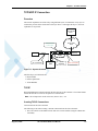
TCP/UDP IP Connection . . . . . . . . . . . . . . . . . . . . . . . . . . . . . . . . . . . . . . . . . . . . . . . . . . . . . . . 1-5
Overview. . . . . . . . . . . . . . . . . . . . . . . . . . . . . . . . . . . . . . . . . . . . . . . . . . . . . . . . . . . . . . . . . . 1-5
TCP/IP . . . . . . . . . . . . . . . . . . . . . . . . . . . . . . . . . . . . . . . . . . . . . . . . . . . . . . . . . . . . . . . . . . . 1-5
UDP/IP . . . . . . . . . . . . . . . . . . . . . . . . . . . . . . . . . . . . . . . . . . . . . . . . . . . . . . . . . . . . . . . . . . . 1-7
Online Data Mode. . . . . . . . . . . . . . . . . . . . . . . . . . . . . . . . . . . . . . . . . . . . . . . . . . . . . . . . . . . 1-8
SSL . . . . . . . . . . . . . . . . . . . . . . . . . . . . . . . . . . . . . . . . . . . . . . . . . . . . . . . . . . . . . . . . . . . . . . 1-9
Features and Benefits . . . . . . . . . . . . . . . . . . . . . . . . . . . . . . . . . . . . . . . . . . . . . . . . . . . . . . . . 1-9
Technical Description . . . . . . . . . . . . . . . . . . . . . . . . . . . . . . . . . . . . . . . . . . . . . . . . . . . . . . . 1-10
FTP Connection . . . . . . . . . . . . . . . . . . . . . . . . . . . . . . . . . . . . . . . . . . . . . . . . . . . . . . . . . . . . . 1-10
Overview. . . . . . . . . . . . . . . . . . . . . . . . . . . . . . . . . . . . . . . . . . . . . . . . . . . . . . . . . . . . . . . . . 1-10
Manage FTP Connection . . . . . . . . . . . . . . . . . . . . . . . . . . . . . . . . . . . . . . . . . . . . . . . . . . . . 1-11
Manage Remote File System . . . . . . . . . . . . . . . . . . . . . . . . . . . . . . . . . . . . . . . . . . . . . . . . . 1-12
File Transfer Operations . . . . . . . . . . . . . . . . . . . . . . . . . . . . . . . . . . . . . . . . . . . . . . . . . . . . . 1-12
Other FTP Operations. . . . . . . . . . . . . . . . . . . . . . . . . . . . . . . . . . . . . . . . . . . . . . . . . . . . . . . 1-13
Interaction with Other MIP Commands . . . . . . . . . . . . . . . . . . . . . . . . . . . . . . . . . . . . . . . . . 1-13
Audio . . . . . . . . . . . . . . . . . . . . . . . . . . . . . . . . . . . . . . . . . . . . . . . . . . . . . . . . . . . . . . . . . . . . . 1-14
Overview. . . . . . . . . . . . . . . . . . . . . . . . . . . . . . . . . . . . . . . . . . . . . . . . . . . . . . . . . . . . . . . . . 1-14
Features and Benefits . . . . . . . . . . . . . . . . . . . . . . . . . . . . . . . . . . . . . . . . . . . . . . . . . . . . . . . 1-14
Technical Description . . . . . . . . . . . . . . . . . . . . . . . . . . . . . . . . . . . . . . . . . . . . . . . . . . . . . . . 1-15
MUX Integration . . . . . . . . . . . . . . . . . . . . . . . . . . . . . . . . . . . . . . . . . . . . . . . . . . . . . . . . . . . . . . . 1-16
Overview . . . . . . . . . . . . . . . . . . . . . . . . . . . . . . . . . . . . . . . . . . . . . . . . . . . . . . . . . . . . . . . . . . 1-16
Features and Benefits . . . . . . . . . . . . . . . . . . . . . . . . . . . . . . . . . . . . . . . . . . . . . . . . . . . . . . . . . 1-16
Technical Description . . . . . . . . . . . . . . . . . . . . . . . . . . . . . . . . . . . . . . . . . . . . . . . . . . . . . . . . . 1-17
Short Message Service (SMS) . . . . . . . . . . . . . . . . . . . . . . . . . . . . . . . . . . . . . . . . . . . . . . . . . . . . . 1-18
Overview . . . . . . . . . . . . . . . . . . . . . . . . . . . . . . . . . . . . . . . . . . . . . . . . . . . . . . . . . . . . . . . . . . 1-18
Features . . . . . . . . . . . . . . . . . . . . . . . . . . . . . . . . . . . . . . . . . . . . . . . . . . . . . . . . . . . . . . . . . . . 1-18
Technical Description . . . . . . . . . . . . . . . . . . . . . . . . . . . . . . . . . . . . . . . . . . . . . . . . . . . . . . . . . 1-19
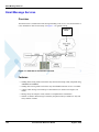
Email Message Services . . . . . . . . . . . . . . . . . . . . . . . . . . . . . . . . . . . . . . . . . . . . . . . . . . . . . . . . . 1-20
Overview . . . . . . . . . . . . . . . . . . . . . . . . . . . . . . . . . . . . . . . . . . . . . . . . . . . . . . . . . . . . . . . . . . 1-20
Features . . . . . . . . . . . . . . . . . . . . . . . . . . . . . . . . . . . . . . . . . . . . . . . . . . . . . . . . . . . . . . . . . . . 1-20
Fax . . . . . . . . . . . . . . . . . . . . . . . . . . . . . . . . . . . . . . . . . . . . . . . . . . . . . . . . . . . . . . . . . . . . . . . . . . 1-21
Overview . . . . . . . . . . . . . . . . . . . . . . . . . . . . . . . . . . . . . . . . . . . . . . . . . . . . . . . . . . . . . . . . . . 1-21
Features and Benefits . . . . . . . . . . . . . . . . . . . . . . . . . . . . . . . . . . . . . . . . . . . . . . . . . . . . . . . . . 1-21
Technical Description . . . . . . . . . . . . . . . . . . . . . . . . . . . . . . . . . . . . . . . . . . . . . . . . . . . . . . . . . 1-21
Character Sets . . . . . . . . . . . . . . . . . . . . . . . . . . . . . . . . . . . . . . . . . . . . . . . . . . . . . . . . . . . . . . . . . 1-22
ASCII Character Set Management . . . . . . . . . . . . . . . . . . . . . . . . . . . . . . . . . . . . . . . . . . . . . . . 1-22
GSM Character Set Management . . . . . . . . . . . . . . . . . . . . . . . . . . . . . . . . . . . . . . . . . . . . . . . . 1-22
UCS2 Character Set Management . . . . . . . . . . . . . . . . . . . . . . . . . . . . . . . . . . . . . . . . . . . . . . . 1-22
UTF-8 Character Set Management . . . . . . . . . . . . . . . . . . . . . . . . . . . . . . . . . . . . . . . . . . . . . . . 1-22
8859-1 Character Set Management . . . . . . . . . . . . . . . . . . . . . . . . . . . . . . . . . . . . . . . . . . . . . . 1-23
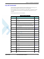
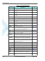
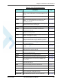
AT Commands Summary . . . . . . . . . . . . . . . . . . . . . . . . . . . . . . . . . . . . . . . . . . . . . . . . . . . . . . . . 1-24
Chapter 2:
ii
Introduction to AT Commands . . . . . . . . . . . . . . . . . . . . . . . . . . . . . . . . . . . . . . . . . . . . 2-1
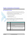
AT Commands Overview . . . . . . . . . . . . . . . . . . . . . . . . . . . . . . . . . . . . . . . . . . . . . . . . . . . . . . . . . 2-1
General Symbols Used in AT Commands Description . . . . . . . . . . . . . . . . . . . . . . . . . . . . . . . . 2-1
General System Abbreviations . . . . . . . . . . . . . . . . . . . . . . . . . . . . . . . . . . . . . . . . . . . . . . . . . . . 2-2
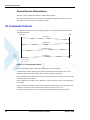
AT Commands Protocol . . . . . . . . . . . . . . . . . . . . . . . . . . . . . . . . . . . . . . . . . . . . . . . . . . . . . . . . . . 2-2
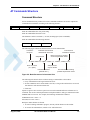
AT Commands Structure . . . . . . . . . . . . . . . . . . . . . . . . . . . . . . . . . . . . . . . . . . . . . . . . . . . . . . . . . . 2-3
Command Structure . . . . . . . . . . . . . . . . . . . . . . . . . . . . . . . . . . . . . . . . . . . . . . . . . . . . . . . . . . . 2-3
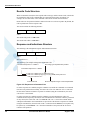
Results Code Structure . . . . . . . . . . . . . . . . . . . . . . . . . . . . . . . . . . . . . . . . . . . . . . . . . . . . . . . . . 2-4
Response and Indications Structure . . . . . . . . . . . . . . . . . . . . . . . . . . . . . . . . . . . . . . . . . . . . . . . 2-4
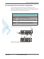
AT Commands Protocol & Structure Configuration . . . . . . . . . . . . . . . . . . . . . . . . . . . . . . . . . . . . . 2-5
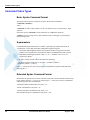
Command Token Types . . . . . . . . . . . . . . . . . . . . . . . . . . . . . . . . . . . . . . . . . . . . . . . . . . . . . . . . . . . 2-6
Basic Syntax Command Format . . . . . . . . . . . . . . . . . . . . . . . . . . . . . . . . . . . . . . . . . . . . . . . . . . 2-6
AT Commands Reference Manual
August 5, 2008
Table of Contents
S-parameters . . . . . . . . . . . . . . . . . . . . . . . . . . . . . . . . . . . . . . . . . . . . . . . . . . . . . . . . . . . . . . . .
Extended Syntax Command Format . . . . . . . . . . . . . . . . . . . . . . . . . . . . . . . . . . . . . . . . . . . . . .
Command Argument Types. . . . . . . . . . . . . . . . . . . . . . . . . . . . . . . . . . . . . . . . . . . . . . . . . . . . . . . .
Numeric Constants . . . . . . . . . . . . . . . . . . . . . . . . . . . . . . . . . . . . . . . . . . . . . . . . . . . . . . . . . . . .
String Constants . . . . . . . . . . . . . . . . . . . . . . . . . . . . . . . . . . . . . . . . . . . . . . . . . . . . . . . . . . . . . .
Command Mode Types . . . . . . . . . . . . . . . . . . . . . . . . . . . . . . . . . . . . . . . . . . . . . . . . . . . . . . . . . . .
Parameter Set Command Syntax . . . . . . . . . . . . . . . . . . . . . . . . . . . . . . . . . . . . . . . . . . . . . . . . .
Parameter Read Command Syntax . . . . . . . . . . . . . . . . . . . . . . . . . . . . . . . . . . . . . . . . . . . . . . .
Parameter Test Command Syntax . . . . . . . . . . . . . . . . . . . . . . . . . . . . . . . . . . . . . . . . . . . . . . . .
Values . . . . . . . . . . . . . . . . . . . . . . . . . . . . . . . . . . . . . . . . . . . . . . . . . . . . . . . . . . . . . . . . . . . . . . . .
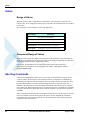
Range of Values . . . . . . . . . . . . . . . . . . . . . . . . . . . . . . . . . . . . . . . . . . . . . . . . . . . . . . . . . . . . . .
Compound Range of Values . . . . . . . . . . . . . . . . . . . . . . . . . . . . . . . . . . . . . . . . . . . . . . . . . . . .
Aborting Commands . . . . . . . . . . . . . . . . . . . . . . . . . . . . . . . . . . . . . . . . . . . . . . . . . . . . . . . . . . . . .
Core AT Commands . . . . . . . . . . . . . . . . . . . . . . . . . . . . . . . . . . . . . . . . . . . . . . . . . . . . . . . . . . . . .
Chapter 3:
2-6
2-6
2-7
2-7
2-7
2-7
2-7
2-7
2-7
2-8
2-8
2-8
2-8
2-9
AT Commands Reference. . . . . . . . . . . . . . . . . . . . . . . . . . . . . . . . . . . . . . . . . . . . . . . . .3-1
Modem ID . . . . . . . . . . . . . . . . . . . . . . . . . . . . . . . . . . . . . . . . . . . . . . . . . . . . . . . . . . . . . . . . . . . . . 3-1
Subscriber Unit Identity . . . . . . . . . . . . . . . . . . . . . . . . . . . . . . . . . . . . . . . . . . . . . . . . . . . . . . . . 3-1
+CGMI, +GMI, +FMI, Request Manufacturer ID . . . . . . . . . . . . . . . . . . . . . . . . . . . . . . . . . . 3-1
+CGMM, +GMM, +FMM, Request Model ID . . . . . . . . . . . . . . . . . . . . . . . . . . . . . . . . . . . . 3-2
+CGMR, +GMR, +FMR, Request Revision . . . . . . . . . . . . . . . . . . . . . . . . . . . . . . . . . . . . . . 3-3
+CGSN, +GSN, Request Product Serial Number Identification . . . . . . . . . . . . . . . . . . . . . . . 3-3
+CSCS, Select Terminal Character Set . . . . . . . . . . . . . . . . . . . . . . . . . . . . . . . . . . . . . . . . . . 3-4
+CIMI, Request IMSI . . . . . . . . . . . . . . . . . . . . . . . . . . . . . . . . . . . . . . . . . . . . . . . . . . . . . . . 3-6
+CFSN, Read Factory Serial Number . . . . . . . . . . . . . . . . . . . . . . . . . . . . . . . . . . . . . . . . . . . 3-6
I, Request Identification Information . . . . . . . . . . . . . . . . . . . . . . . . . . . . . . . . . . . . . . . . . . . . 3-6
+CNUM, Request MSISDN(s) . . . . . . . . . . . . . . . . . . . . . . . . . . . . . . . . . . . . . . . . . . . . . . . . 3-7
$, List of All Available AT Commands . . . . . . . . . . . . . . . . . . . . . . . . . . . . . . . . . . . . . . . . . 3-8
+CLAC, List of All Available AT Commands . . . . . . . . . . . . . . . . . . . . . . . . . . . . . . . . . . . . 3-9
Capability Reporting . . . . . . . . . . . . . . . . . . . . . . . . . . . . . . . . . . . . . . . . . . . . . . . . . . . . . . . . . 3-10
Call Control . . . . . . . . . . . . . . . . . . . . . . . . . . . . . . . . . . . . . . . . . . . . . . . . . . . . . . . . . . . . . . . . . . . 3-11
Managing a CSD (Data) Call . . . . . . . . . . . . . . . . . . . . . . . . . . . . . . . . . . . . . . . . . . . . . . . . . . . 3-11
Simple Dialing . . . . . . . . . . . . . . . . . . . . . . . . . . . . . . . . . . . . . . . . . . . . . . . . . . . . . . . . . . . . 3-11
Switching From Data Mode to Command Mode . . . . . . . . . . . . . . . . . . . . . . . . . . . . . . . . . . 3-12
Hanging Up . . . . . . . . . . . . . . . . . . . . . . . . . . . . . . . . . . . . . . . . . . . . . . . . . . . . . . . . . . . . . . 3-12
Dialing to an Electronic Telephone Service. . . . . . . . . . . . . . . . . . . . . . . . . . . . . . . . . . . . . . 3-12
Receiving a Data Call . . . . . . . . . . . . . . . . . . . . . . . . . . . . . . . . . . . . . . . . . . . . . . . . . . . . . . . . 3-12
August 5, 2008
AT Commands Reference Manual
iii
Table of Contents
Call Control AT Commands . . . . . . . . . . . . . . . . . . . . . . . . . . . . . . . . . . . . . . . . . . . . . . . . . . . .
D, Dial Command . . . . . . . . . . . . . . . . . . . . . . . . . . . . . . . . . . . . . . . . . . . . . . . . . . . . . . . . .
D>, Direct Dialing from Phone Books . . . . . . . . . . . . . . . . . . . . . . . . . . . . . . . . . . . . . . . . . .
DL, Dial Last Number . . . . . . . . . . . . . . . . . . . . . . . . . . . . . . . . . . . . . . . . . . . . . . . . . . . . . .
H, Hang-up Call . . . . . . . . . . . . . . . . . . . . . . . . . . . . . . . . . . . . . . . . . . . . . . . . . . . . . . . . . . .
A, Answer Incoming Call . . . . . . . . . . . . . . . . . . . . . . . . . . . . . . . . . . . . . . . . . . . . . . . . . . .
+CRC, Cellular Result Codes and RING, +CRING - Incoming Call Indication . . . . . . . . . .
+CLIP, Calling Line Identification . . . . . . . . . . . . . . . . . . . . . . . . . . . . . . . . . . . . . . . . . . . .
+CCWA, Call Waiting Command . . . . . . . . . . . . . . . . . . . . . . . . . . . . . . . . . . . . . . . . . . . . .
+CHLD, Call Related Supplementary Services Command . . . . . . . . . . . . . . . . . . . . . . . . . .
+CCFC, Call Forwarding Number and Conditions . . . . . . . . . . . . . . . . . . . . . . . . . . . . . . . .
+CLIR, Calling Line Identification Restriction . . . . . . . . . . . . . . . . . . . . . . . . . . . . . . . . . . .
+CBST, Select Bearer Service Type . . . . . . . . . . . . . . . . . . . . . . . . . . . . . . . . . . . . . . . . . . .
O, Return to Online Data State . . . . . . . . . . . . . . . . . . . . . . . . . . . . . . . . . . . . . . . . . . . . . . .
&Q, Asynchronous Mode . . . . . . . . . . . . . . . . . . . . . . . . . . . . . . . . . . . . . . . . . . . . . . . . . . . .
+CHUP, Hang Up Call . . . . . . . . . . . . . . . . . . . . . . . . . . . . . . . . . . . . . . . . . . . . . . . . . . . . . .
+CSNS, Single Numbering Call Scheme . . . . . . . . . . . . . . . . . . . . . . . . . . . . . . . . . . . . . . . .
+MDC, Selection of Desired Message to Be Displayed Upon Connection of a Voice Call .
+CTFR1, Divert an Incoming Call When User Busy. . . . . . . . . . . . . . . . . . . . . . . . . . . . . . .
+MFIC, Filtering Incoming Calls . . . . . . . . . . . . . . . . . . . . . . . . . . . . . . . . . . . . . . . . . . . . . .
+MHUP, Motorola Hung UP call . . . . . . . . . . . . . . . . . . . . . . . . . . . . . . . . . . . . . . . . . . . . . .
+MVC, Motorola Vocoders Configuration . . . . . . . . . . . . . . . . . . . . . . . . . . . . . . . . . . . . . .
+MTTY, Motorola TTY Configuration . . . . . . . . . . . . . . . . . . . . . . . . . . . . . . . . . . . . . . . . .
Call Status Messages . . . . . . . . . . . . . . . . . . . . . . . . . . . . . . . . . . . . . . . . . . . . . . . . . . . . . . . . .
+CPAS, Phone Activity Status . . . . . . . . . . . . . . . . . . . . . . . . . . . . . . . . . . . . . . . . . . . . . . .
+CLCC, List Current Calls . . . . . . . . . . . . . . . . . . . . . . . . . . . . . . . . . . . . . . . . . . . . . . . . . . .
+MCST, Call Status Messages . . . . . . . . . . . . . . . . . . . . . . . . . . . . . . . . . . . . . . . . . . . . . . . .
+TCLCC, List Current Calls. . . . . . . . . . . . . . . . . . . . . . . . . . . . . . . . . . . . . . . . . . . . . . . . . .
+MNTFY, Motorola NoTiFY Indication . . . . . . . . . . . . . . . . . . . . . . . . . . . . . . . . . . . . . . . .
Call Advice of Charge Commands . . . . . . . . . . . . . . . . . . . . . . . . . . . . . . . . . . . . . . . . . . . . . . .
+CAOC, Advice of Charge . . . . . . . . . . . . . . . . . . . . . . . . . . . . . . . . . . . . . . . . . . . . . . . . . .
+CACM, Accumulated Call Meter. . . . . . . . . . . . . . . . . . . . . . . . . . . . . . . . . . . . . . . . . . . . .
+CAMM, Accumulated Call Meter Maximum . . . . . . . . . . . . . . . . . . . . . . . . . . . . . . . . . . .
+CPUC, Price per Unit and Currency Table . . . . . . . . . . . . . . . . . . . . . . . . . . . . . . . . . . . . .
+CR, Service Reporting Control. . . . . . . . . . . . . . . . . . . . . . . . . . . . . . . . . . . . . . . . . . . . . . .
Supplementary Services . . . . . . . . . . . . . . . . . . . . . . . . . . . . . . . . . . . . . . . . . . . . . . . . . . . . . . .
+CSSN, Supplementary Service Notifications . . . . . . . . . . . . . . . . . . . . . . . . . . . . . . . . . . . .
+CUSD, Unstructured Supplementary Service Data . . . . . . . . . . . . . . . . . . . . . . . . . . . . . . .
+COLP, Connected Line Identification Presentation . . . . . . . . . . . . . . . . . . . . . . . . . . . . . . .
Phone and Date Books and Clock . . . . . . . . . . . . . . . . . . . . . . . . . . . . . . . . . . . . . . . . . . . . . . . . . .
Directory Access Commands - Phone Book . . . . . . . . . . . . . . . . . . . . . . . . . . . . . . . . . . . . . . .
+CPBS, Select Phone Book Memory . . . . . . . . . . . . . . . . . . . . . . . . . . . . . . . . . . . . . . . . . . .
+CPBR, Read Phone Book Entries . . . . . . . . . . . . . . . . . . . . . . . . . . . . . . . . . . . . . . . . . . . .
+CPBF, Find Phone Book Entries . . . . . . . . . . . . . . . . . . . . . . . . . . . . . . . . . . . . . . . . . . . . .
+CPBW, Write Phone Book Entry . . . . . . . . . . . . . . . . . . . . . . . . . . . . . . . . . . . . . . . . . . . .
+CSVM, Set Voice Mail Server . . . . . . . . . . . . . . . . . . . . . . . . . . . . . . . . . . . . . . . . . . . . . . .
+MDSI, Motorola Deactivate SIM Card Indication . . . . . . . . . . . . . . . . . . . . . . . . . . . . . . . .
+MCSN, Motorola Change Subscriber Number . . . . . . . . . . . . . . . . . . . . . . . . . . . . . . . . . .
+MPDPM, Motorola Phonebook Dynamic Percentage Memory. . . . . . . . . . . . . . . . . . . . . .
iv
AT Commands Reference Manual
3-13
3-13
3-14
3-16
3-17
3-19
3-19
3-21
3-23
3-25
3-29
3-31
3-33
3-34
3-35
3-35
3-36
3-38
3-39
3-40
3-42
3-43
3-44
3-46
3-46
3-47
3-49
3-51
3-53
3-55
3-55
3-57
3-58
3-60
3-61
3-62
3-62
3-65
3-69
3-71
3-71
3-71
3-73
3-75
3-76
3-77
3-78
3-81
3-85
August 5, 2008
Table of Contents
Directory Access Commands - Date Book . . . . . . . . . . . . . . . . . . . . . . . . . . . . . . . . . . . . . . . . 3-86
+MALARM, Date Book Reminder Unsolicited Report . . . . . . . . . . . . . . . . . . . . . . . . . . . . 3-86
+MALMH, Terminate the Current Reminder . . . . . . . . . . . . . . . . . . . . . . . . . . . . . . . . . . . . 3-87
+MDBGD, Defines General Setting for Date Book. . . . . . . . . . . . . . . . . . . . . . . . . . . . . . . . 3-88
+MDBR, Read Date Book Entries . . . . . . . . . . . . . . . . . . . . . . . . . . . . . . . . . . . . . . . . . . . . . 3-89
+MDBW, Write Date Book Entry . . . . . . . . . . . . . . . . . . . . . . . . . . . . . . . . . . . . . . . . . . . . . 3-91
+MDBWE, Write Date Book Exception . . . . . . . . . . . . . . . . . . . . . . . . . . . . . . . . . . . . . . . . 3-93
System Date and Time Access Commands . . . . . . . . . . . . . . . . . . . . . . . . . . . . . . . . . . . . . . . . 3-96
+CCLK, Read/Set System Date and Time . . . . . . . . . . . . . . . . . . . . . . . . . . . . . . . . . . . . . . 3-96
SMS . . . . . . . . . . . . . . . . . . . . . . . . . . . . . . . . . . . . . . . . . . . . . . . . . . . . . . . . . . . . . . . . . . . . . . . . . 3-98
SMS Commands . . . . . . . . . . . . . . . . . . . . . . . . . . . . . . . . . . . . . . . . . . . . . . . . . . . . . . . . . . . . 3-98
+CSMS, Select Message Service. . . . . . . . . . . . . . . . . . . . . . . . . . . . . . . . . . . . . . . . . . . . . . 3-98
+CPMS, Preferred Message Storage . . . . . . . . . . . . . . . . . . . . . . . . . . . . . . . . . . . . . . . . . . . 3-99
+CMGF, Message Format . . . . . . . . . . . . . . . . . . . . . . . . . . . . . . . . . . . . . . . . . . . . . . . . . . 3-101
+CSCA, Service Center Address . . . . . . . . . . . . . . . . . . . . . . . . . . . . . . . . . . . . . . . . . . . . 3-101
+CSMP, Set Text Mode Parameters . . . . . . . . . . . . . . . . . . . . . . . . . . . . . . . . . . . . . . . . . . 3-104
+CSDH, Show Text Mode Parameters . . . . . . . . . . . . . . . . . . . . . . . . . . . . . . . . . . . . . . . . 3-106
+CNMI, New Message Indications to Terminal . . . . . . . . . . . . . . . . . . . . . . . . . . . . . . . . . 3-107
+CNMA, New Message Acknowledgment . . . . . . . . . . . . . . . . . . . . . . . . . . . . . . . . . . . . . 3-108
+CMTI, Unsolicited Response (New SMS-DELIVER Receipt Indication) . . . . . . . . . . . . 3-110
+CMT, Unsolicited Response (New SMS-DELIVER Receipt) . . . . . . . . . . . . . . . . . . . . . 3-110
+CBM, Unsolicited Response (New CB Message Receipt) . . . . . . . . . . . . . . . . . . . . . . . . 3-112
+CDSI, Unsolicited Response (New SMS-STATUS-REPORT Indication) . . . . . . . . . . . . 3-112
+CDS, Unsolicited Response (New SMS-STATUS-REPORT Receipt). . . . . . . . . . . . . . . 3-113
+CMGL, +MMGL, List Messages . . . . . . . . . . . . . . . . . . . . . . . . . . . . . . . . . . . . . . . . . . . 3-114
+CMGR, +MMGR, Read Message . . . . . . . . . . . . . . . . . . . . . . . . . . . . . . . . . . . . . . . . . . . 3-118
+MMAR, Motorola Mark As Read . . . . . . . . . . . . . . . . . . . . . . . . . . . . . . . . . . . . . . . . . . . 3-125
+CMSS, Send Message From Storage . . . . . . . . . . . . . . . . . . . . . . . . . . . . . . . . . . . . . . . . 3-125
+CMGW, Write Message to Memory . . . . . . . . . . . . . . . . . . . . . . . . . . . . . . . . . . . . . . . . . 3-127
+CMGD, Delete Message . . . . . . . . . . . . . . . . . . . . . . . . . . . . . . . . . . . . . . . . . . . . . . . . . . 3-132
+CGSMS, Select Service for MO SMS Messages. . . . . . . . . . . . . . . . . . . . . . . . . . . . . . . . 3-133
+CMGS, Send SM to Network . . . . . . . . . . . . . . . . . . . . . . . . . . . . . . . . . . . . . . . . . . . . . . 3-134
+CSCB, Cell Broadcast Messages . . . . . . . . . . . . . . . . . . . . . . . . . . . . . . . . . . . . . . . . . . . . 3-135
+MCSAT, Motorola Control SMS Alert Tone . . . . . . . . . . . . . . . . . . . . . . . . . . . . . . . . . . 3-137
+MEDT, Motorola Enable/Disable Tone. . . . . . . . . . . . . . . . . . . . . . . . . . . . . . . . . . . . . . . 3-139
+TSMSRET, Control SMS Sending Retry . . . . . . . . . . . . . . . . . . . . . . . . . . . . . . . . . . . . . 3-143
+MRICS, Motorola Ring Indicator Configuration for SMS . . . . . . . . . . . . . . . . . . . . . . . . 3-143
DCS handling . . . . . . . . . . . . . . . . . . . . . . . . . . . . . . . . . . . . . . . . . . . . . . . . . . . . . . . . . . . . 3-145
Email . . . . . . . . . . . . . . . . . . . . . . . . . . . . . . . . . . . . . . . . . . . . . . . . . . . . . . . . . . . . . . . . . . . . . . . 3-150
Email Services AT Commands . . . . . . . . . . . . . . . . . . . . . . . . . . . . . . . . . . . . . . . . . . . . . . . . 3-150
+MEMISP, Email Account ISP (Internet Service Provider) Settings . . . . . . . . . . . . . . . . . 3-150
+MEMAS, Email Account Settings . . . . . . . . . . . . . . . . . . . . . . . . . . . . . . . . . . . . . . . . . . . 3-151
+MEMGS, Email Account General Settings . . . . . . . . . . . . . . . . . . . . . . . . . . . . . . . . . . . . 3-153
+MEMDE, Download Email Message. . . . . . . . . . . . . . . . . . . . . . . . . . . . . . . . . . . . . . . . . 3-155
+MEMSE, Send Email Message . . . . . . . . . . . . . . . . . . . . . . . . . . . . . . . . . . . . . . . . . . . . . 3-157
+MEML, List Email Messages . . . . . . . . . . . . . . . . . . . . . . . . . . . . . . . . . . . . . . . . . . . . . . 3-160
+MEMR, Read Email Message . . . . . . . . . . . . . . . . . . . . . . . . . . . . . . . . . . . . . . . . . . . . . . 3-163
+MEMD, Delete Email Message . . . . . . . . . . . . . . . . . . . . . . . . . . . . . . . . . . . . . . . . . . . . . 3-164
+MEMW, Write or Update Email Message. . . . . . . . . . . . . . . . . . . . . . . . . . . . . . . . . . . . . 3-166
+MEGA, Email Gateway Address . . . . . . . . . . . . . . . . . . . . . . . . . . . . . . . . . . . . . . . . . . . . 3-167
Network . . . . . . . . . . . . . . . . . . . . . . . . . . . . . . . . . . . . . . . . . . . . . . . . . . . . . . . . . . . . . . . . . . . . . 3-169
August 5, 2008
AT Commands Reference Manual
v
Table of Contents
Network Commands . . . . . . . . . . . . . . . . . . . . . . . . . . . . . . . . . . . . . . . . . . . . . . . . . . . . . . . . .
+CSQ, Signal Strength . . . . . . . . . . . . . . . . . . . . . . . . . . . . . . . . . . . . . . . . . . . . . . . . . . . . .
+CRLP, Radio Link Protocol . . . . . . . . . . . . . . . . . . . . . . . . . . . . . . . . . . . . . . . . . . . . . . . .
+CREG, Network Registration Status . . . . . . . . . . . . . . . . . . . . . . . . . . . . . . . . . . . . . . . . .
+CGREG, GPRS Network Registration . . . . . . . . . . . . . . . . . . . . . . . . . . . . . . . . . . . . . . .
+COPS, Operator Selection . . . . . . . . . . . . . . . . . . . . . . . . . . . . . . . . . . . . . . . . . . . . . . . . .
+CPOL, Preferred Operators . . . . . . . . . . . . . . . . . . . . . . . . . . . . . . . . . . . . . . . . . . . . . . . .
+CPLS, Selection of Preferred PLMN List. . . . . . . . . . . . . . . . . . . . . . . . . . . . . . . . . . . . . .
+MFS, Motorola Frequency of Search . . . . . . . . . . . . . . . . . . . . . . . . . . . . . . . . . . . . . . . . .
+MCELL, Motorola Cell Description . . . . . . . . . . . . . . . . . . . . . . . . . . . . . . . . . . . . . . . . .
+ MGAUTH, Enable Authentication Protocol Setting (CHAP/PAP) . . . . . . . . . . . . . . . . .
+MCI, Motorola Cell Information . . . . . . . . . . . . . . . . . . . . . . . . . . . . . . . . . . . . . . . . . . . .
+MJDC, Jamming Detection . . . . . . . . . . . . . . . . . . . . . . . . . . . . . . . . . . . . . . . . . . . . . . . .
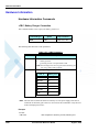
Hardware Information . . . . . . . . . . . . . . . . . . . . . . . . . . . . . . . . . . . . . . . . . . . . . . . . . . . . . . . . . .
Hardware Information Commands . . . . . . . . . . . . . . . . . . . . . . . . . . . . . . . . . . . . . . . . . . . . . .
+CBC, Battery Charger Connection . . . . . . . . . . . . . . . . . . . . . . . . . . . . . . . . . . . . . . . . . .
+CBAUD, Baud Rate Regulation. . . . . . . . . . . . . . . . . . . . . . . . . . . . . . . . . . . . . . . . . . . . .
+IPR, Local Terminal/G24 Serial Port Rate. . . . . . . . . . . . . . . . . . . . . . . . . . . . . . . . . . . . .
+GCAP, Request Overall Capabilities . . . . . . . . . . . . . . . . . . . . . . . . . . . . . . . . . . . . . . . .
+MTDTR, DTR Line Test Command . . . . . . . . . . . . . . . . . . . . . . . . . . . . . . . . . . . . . . . . .
+MTCTS, CTS Line Test Command . . . . . . . . . . . . . . . . . . . . . . . . . . . . . . . . . . . . . . . . . .
&K, RTS/CTS Flow Control . . . . . . . . . . . . . . . . . . . . . . . . . . . . . . . . . . . . . . . . . . . . . . . .
&C, Circuit 109 Behavior. . . . . . . . . . . . . . . . . . . . . . . . . . . . . . . . . . . . . . . . . . . . . . . . . . .
&D, Circuit 108 Behavior. . . . . . . . . . . . . . . . . . . . . . . . . . . . . . . . . . . . . . . . . . . . . . . . . . .
+MCWAKE, GPRS Coverage . . . . . . . . . . . . . . . . . . . . . . . . . . . . . . . . . . . . . . . . . . . . . . .
+MGGIND, GSM/GPRS Service Indicator . . . . . . . . . . . . . . . . . . . . . . . . . . . . . . . . . . . . .
+CFUN, Shut Down Phone Functionality . . . . . . . . . . . . . . . . . . . . . . . . . . . . . . . . . . . . . .
+ICF, DTE-DCE Character Framing . . . . . . . . . . . . . . . . . . . . . . . . . . . . . . . . . . . . . . . . . .
ATS97, Antenna Diagnostic . . . . . . . . . . . . . . . . . . . . . . . . . . . . . . . . . . . . . . . . . . . . . . . . .
+MRST, Perform Hard Reset . . . . . . . . . . . . . . . . . . . . . . . . . . . . . . . . . . . . . . . . . . . . . . . .
+TWUS, Wakeup Reason Set. . . . . . . . . . . . . . . . . . . . . . . . . . . . . . . . . . . . . . . . . . . . . . . .
+TWUR, Wakeup Reason Request . . . . . . . . . . . . . . . . . . . . . . . . . . . . . . . . . . . . . . . . . . .
+TASW, Antenna Switch . . . . . . . . . . . . . . . . . . . . . . . . . . . . . . . . . . . . . . . . . . . . . . . . . . .
+TADIAG, Query Antennas ADC Value. . . . . . . . . . . . . . . . . . . . . . . . . . . . . . . . . . . . . . .
READY, Unsolicited Notification (UART Ready Indication). . . . . . . . . . . . . . . . . . . . . . .
+MPSU, Motorola Physical Second Uart . . . . . . . . . . . . . . . . . . . . . . . . . . . . . . . . . . . . . . .
+MIOC, Motorola I/O Configure . . . . . . . . . . . . . . . . . . . . . . . . . . . . . . . . . . . . . . . . . . . . .
+MIOD, Motorola I/O Define . . . . . . . . . . . . . . . . . . . . . . . . . . . . . . . . . . . . . . . . . . . . . . .
+MMAD, Query and Monitor ADC Value . . . . . . . . . . . . . . . . . . . . . . . . . . . . . . . . . . . . .
+MPCMC, Continuous PCM Clock . . . . . . . . . . . . . . . . . . . . . . . . . . . . . . . . . . . . . . . . . . .
+MVREF, Motorola Voltage Reference. . . . . . . . . . . . . . . . . . . . . . . . . . . . . . . . . . . . . . . .
Audio . . . . . . . . . . . . . . . . . . . . . . . . . . . . . . . . . . . . . . . . . . . . . . . . . . . . . . . . . . . . . . . . . . . . . . .
Scope . . . . . . . . . . . . . . . . . . . . . . . . . . . . . . . . . . . . . . . . . . . . . . . . . . . . . . . . . . . . . . . . . . . .
Audio Setup . . . . . . . . . . . . . . . . . . . . . . . . . . . . . . . . . . . . . . . . . . . . . . . . . . . . . . . . . . . . . . .
Basic Audio Setup . . . . . . . . . . . . . . . . . . . . . . . . . . . . . . . . . . . . . . . . . . . . . . . . . . . . . . . .
Advanced Audio Setup . . . . . . . . . . . . . . . . . . . . . . . . . . . . . . . . . . . . . . . . . . . . . . . . . . . . .
General Audio Commands . . . . . . . . . . . . . . . . . . . . . . . . . . . . . . . . . . . . . . . . . . . . . . . . . .
Basic Audio Setup Commands . . . . . . . . . . . . . . . . . . . . . . . . . . . . . . . . . . . . . . . . . . . . . . . . .
+CRSL, Call Ringer Level . . . . . . . . . . . . . . . . . . . . . . . . . . . . . . . . . . . . . . . . . . . . . . . . . .
+CLVL, Loudspeaker Volume . . . . . . . . . . . . . . . . . . . . . . . . . . . . . . . . . . . . . . . . . . . . . . .
+CMUT, Mute/Unmute Currently Active Microphone Path . . . . . . . . . . . . . . . . . . . . . . . .
S94, Sidetone Effect . . . . . . . . . . . . . . . . . . . . . . . . . . . . . . . . . . . . . . . . . . . . . . . . . . . . . . .
S96, Echo Canceling. . . . . . . . . . . . . . . . . . . . . . . . . . . . . . . . . . . . . . . . . . . . . . . . . . . . . . .
vi
AT Commands Reference Manual
3-169
3-169
3-170
3-171
3-173
3-174
3-177
3-179
3-180
3-182
3-193
3-194
3-196
3-199
3-199
3-199
3-200
3-201
3-203
3-203
3-204
3-204
3-205
3-207
3-208
3-209
3-210
3-211
3-212
3-213
3-213
3-215
3-215
3-216
3-217
3-217
3-219
3-223
3-225
3-232
3-233
3-235
3-235
3-236
3-237
3-237
3-238
3-238
3-238
3-239
3-240
3-241
3-242
August 5, 2008
Table of Contents
Advanced Audio Setup Commands . . . . . . . . . . . . . . . . . . . . . . . . . . . . . . . . . . . . . . . . . . . .
+MAPATH, Audio Path . . . . . . . . . . . . . . . . . . . . . . . . . . . . . . . . . . . . . . . . . . . . . . . . . . .
+MAVOL, Volume Setting . . . . . . . . . . . . . . . . . . . . . . . . . . . . . . . . . . . . . . . . . . . . . . . . .
+MAMUT, Input Devices Mute . . . . . . . . . . . . . . . . . . . . . . . . . . . . . . . . . . . . . . . . . . . . .
+MAFEAT, Features Selection . . . . . . . . . . . . . . . . . . . . . . . . . . . . . . . . . . . . . . . . . . . . . .
General Audio Commands . . . . . . . . . . . . . . . . . . . . . . . . . . . . . . . . . . . . . . . . . . . . . . . . . . . .
+MADIGITAL, Analog/Digital Audio Switching. . . . . . . . . . . . . . . . . . . . . . . . . . . . . . . .
+CALM, Alert Sound Mode . . . . . . . . . . . . . . . . . . . . . . . . . . . . . . . . . . . . . . . . . . . . . . . .
+MDMIC, Enable/Disable Microphone Level Setting in Digital Audio Mode. . . . . . . . . .
+ MMICG, Microphone Gain Value . . . . . . . . . . . . . . . . . . . . . . . . . . . . . . . . . . . . . . . . . .
+CRTT, Ring Type Selection. . . . . . . . . . . . . . . . . . . . . . . . . . . . . . . . . . . . . . . . . . . . . . . .
+VTD, Tone Duration . . . . . . . . . . . . . . . . . . . . . . . . . . . . . . . . . . . . . . . . . . . . . . . . . . . . .
+VTS, Command-Specific Tone Duration. . . . . . . . . . . . . . . . . . . . . . . . . . . . . . . . . . . . . .
Access . . . . . . . . . . . . . . . . . . . . . . . . . . . . . . . . . . . . . . . . . . . . . . . . . . . . . . . . . . . . . . . . . . . . . .
Access Control Commands . . . . . . . . . . . . . . . . . . . . . . . . . . . . . . . . . . . . . . . . . . . . . . . . . . .
A/, Repeat Last Command . . . . . . . . . . . . . . . . . . . . . . . . . . . . . . . . . . . . . . . . . . . . . . . . . .
AT, Check AT Communication . . . . . . . . . . . . . . . . . . . . . . . . . . . . . . . . . . . . . . . . . . . . . .
+CPIN, Enter PIN for Unlocking SIM Card or Enter PUK for Unblocking SIM Card . . .
+EPIN, Enter SIM PIN2 to Verify PIN2 Indicator . . . . . . . . . . . . . . . . . . . . . . . . . . . . . . .
+TPIN, Query Number of Remaining SIM PIN/PUK Entering Attempts. . . . . . . . . . . . . .
+CPWD, Change Password . . . . . . . . . . . . . . . . . . . . . . . . . . . . . . . . . . . . . . . . . . . . . . . . .
+CLCK, Facility Lock . . . . . . . . . . . . . . . . . . . . . . . . . . . . . . . . . . . . . . . . . . . . . . . . . . . . .
+EMPC, Unlocking or Locking Subsidy Code . . . . . . . . . . . . . . . . . . . . . . . . . . . . . . . . . .
Firmware Update Over the Air (FOTA) . . . . . . . . . . . . . . . . . . . . . . . . . . . . . . . . . . . . . . . . . . . .
+MFOTAWSCFG, Set the Web-Session Default Entry . . . . . . . . . . . . . . . . . . . . . . . . . . . . .
+MFOTACNFG, Set the DM Session as Automatic/Non-Automatic . . . . . . . . . . . . . . . . . . .
+MFOTAREQ, Sends FOTA Requests Toward DTE . . . . . . . . . . . . . . . . . . . . . . . . . . . . . . .
+MFOTARSP, Respond to +MFOTAREQ Report . . . . . . . . . . . . . . . . . . . . . . . . . . . . . . . . .
+MFOTAINSTL, Install the FOTA Updated Package . . . . . . . . . . . . . . . . . . . . . . . . . . . . . .
+MFOTAABORT, Abort the DM Session . . . . . . . . . . . . . . . . . . . . . . . . . . . . . . . . . . . . . . .
+ MFOTAIND, Send Unsolicited FOTA Indications Toward the DTE . . . . . . . . . . . . . . . . .
+MFOTABS, Initialize OTA Bootstrap Definition to Enable New Bootstrap Process . . . . .
Modem Configuration and Profile . . . . . . . . . . . . . . . . . . . . . . . . . . . . . . . . . . . . . . . . . . . . . . . .
Modem Register Commands . . . . . . . . . . . . . . . . . . . . . . . . . . . . . . . . . . . . . . . . . . . . . . . . . .
V, G24 Response Format . . . . . . . . . . . . . . . . . . . . . . . . . . . . . . . . . . . . . . . . . . . . . . . . . . .
Q, Result Code Suppression. . . . . . . . . . . . . . . . . . . . . . . . . . . . . . . . . . . . . . . . . . . . . . . . .
E, Command Echo . . . . . . . . . . . . . . . . . . . . . . . . . . . . . . . . . . . . . . . . . . . . . . . . . . . . . . . .
X, Result Code Selection and Call Progress Monitoring Control . . . . . . . . . . . . . . . . . . . .
S, Bit Map Registers. . . . . . . . . . . . . . . . . . . . . . . . . . . . . . . . . . . . . . . . . . . . . . . . . . . . . . .
\S, Show the Status of the Commands and S-registers in Effect . . . . . . . . . . . . . . . . . . . . .
\G, Software Control . . . . . . . . . . . . . . . . . . . . . . . . . . . . . . . . . . . . . . . . . . . . . . . . . . . . . .
\J, Terminal Auto Rate . . . . . . . . . . . . . . . . . . . . . . . . . . . . . . . . . . . . . . . . . . . . . . . . . . . . .
\N, Link Type . . . . . . . . . . . . . . . . . . . . . . . . . . . . . . . . . . . . . . . . . . . . . . . . . . . . . . . . . . . .
+CBAND, Change Radio Band . . . . . . . . . . . . . . . . . . . . . . . . . . . . . . . . . . . . . . . . . . . . . .
?, Return the Value of the Last Updated S-register . . . . . . . . . . . . . . . . . . . . . . . . . . . . . . .
&F, Set to Factory Defined Configuration . . . . . . . . . . . . . . . . . . . . . . . . . . . . . . . . . . . . .
Z, Reset to Default Configuration . . . . . . . . . . . . . . . . . . . . . . . . . . . . . . . . . . . . . . . . . . . .
Sleep Mode Commands . . . . . . . . . . . . . . . . . . . . . . . . . . . . . . . . . . . . . . . . . . . . . . . . . . . . . .
Sleep Mode AT Commands . . . . . . . . . . . . . . . . . . . . . . . . . . . . . . . . . . . . . . . . . . . . . . . .
Sleep Mode HW Signals . . . . . . . . . . . . . . . . . . . . . . . . . . . . . . . . . . . . . . . . . . . . . . . . . . .
S24, Set Number of Seconds Delay Before G24 Enters Sleep Mode . . . . . . . . . . . . . . . . .
S102, Set Delay Before Sending Data to the Terminal . . . . . . . . . . . . . . . . . . . . . . . . . . . .
S100, Set Minimum Time for Terminal to Fall into Sleep Mode . . . . . . . . . . . . . . . . . . . .
+MSCTS, Enable/Disable CTS During Wakeup Period . . . . . . . . . . . . . . . . . . . . . . . . . . .
August 5, 2008
AT Commands Reference Manual
3-243
3-243
3-246
3-248
3-249
3-250
3-250
3-251
3-252
3-252
3-253
3-256
3-257
3-258
3-258
3-258
3-258
3-259
3-262
3-263
3-264
3-265
3-268
3-271
3-271
3-273
3-274
3-275
3-276
3-277
3-277
3-279
3-281
3-281
3-281
3-282
3-283
3-284
3-285
3-288
3-288
3-288
3-288
3-288
3-289
3-289
3-290
3-290
3-291
3-291
3-293
3-294
3-295
3-296
vii
Table of Contents
Error Handling Commands . . . . . . . . . . . . . . . . . . . . . . . . . . . . . . . . . . . . . . . . . . . . . . . . . . .
+CMEE, Report Mobile Equipment Error . . . . . . . . . . . . . . . . . . . . . . . . . . . . . . . . . . . . . .
+CEER, Extended Error Report . . . . . . . . . . . . . . . . . . . . . . . . . . . . . . . . . . . . . . . . . . . . . .
+MGEER, GPRS Extended Error Report. . . . . . . . . . . . . . . . . . . . . . . . . . . . . . . . . . . . . . .
UI (User Interface) . . . . . . . . . . . . . . . . . . . . . . . . . . . . . . . . . . . . . . . . . . . . . . . . . . . . . . . . . . . . .
+CRSM, Restricted SIM Access . . . . . . . . . . . . . . . . . . . . . . . . . . . . . . . . . . . . . . . . . . . . . . .
&V, View Configuration . . . . . . . . . . . . . . . . . . . . . . . . . . . . . . . . . . . . . . . . . . . . . . . . . . . . .
&W, Store User Profile . . . . . . . . . . . . . . . . . . . . . . . . . . . . . . . . . . . . . . . . . . . . . . . . . . . . . .
&Y, Default User Profile . . . . . . . . . . . . . . . . . . . . . . . . . . . . . . . . . . . . . . . . . . . . . . . . . . . . .
+CKPD, Keypad Control . . . . . . . . . . . . . . . . . . . . . . . . . . . . . . . . . . . . . . . . . . . . . . . . . . . .
+MKPD, Auxiliary Keypad Control . . . . . . . . . . . . . . . . . . . . . . . . . . . . . . . . . . . . . . . . . . . .
+CMER, Mobile Equipment Event Reporting . . . . . . . . . . . . . . . . . . . . . . . . . . . . . . . . . . . . .
+CLAN, ME Language . . . . . . . . . . . . . . . . . . . . . . . . . . . . . . . . . . . . . . . . . . . . . . . . . . . . . .
+CIND, Indicator Control . . . . . . . . . . . . . . . . . . . . . . . . . . . . . . . . . . . . . . . . . . . . . . . . . . . .
+MHDPB, Motorola Headset Dual-position Button . . . . . . . . . . . . . . . . . . . . . . . . . . . . . . . .
Unsolicited UI Status Messages . . . . . . . . . . . . . . . . . . . . . . . . . . . . . . . . . . . . . . . . . . . . . . . .
+CKEV, Key Press Echo Output . . . . . . . . . . . . . . . . . . . . . . . . . . . . . . . . . . . . . . . . . . . . .
+CDEV, Change Display Indication . . . . . . . . . . . . . . . . . . . . . . . . . . . . . . . . . . . . . . . . . .
+CIEV, Indicator Event Reporting . . . . . . . . . . . . . . . . . . . . . . . . . . . . . . . . . . . . . . . . . . . .
+MUPB, Phone Book Event . . . . . . . . . . . . . . . . . . . . . . . . . . . . . . . . . . . . . . . . . . . . . . . .
GPRS/EDGE . . . . . . . . . . . . . . . . . . . . . . . . . . . . . . . . . . . . . . . . . . . . . . . . . . . . . . . . . . . . . . . . .
GPRS Functionality . . . . . . . . . . . . . . . . . . . . . . . . . . . . . . . . . . . . . . . . . . . . . . . . . . . . . . . . .
GPRS Commands . . . . . . . . . . . . . . . . . . . . . . . . . . . . . . . . . . . . . . . . . . . . . . . . . . . . . . . . . . .
+CGCLASS, GPRS Mobile Station Class . . . . . . . . . . . . . . . . . . . . . . . . . . . . . . . . . . . . . .
+CGDCONT, Define PDP Context . . . . . . . . . . . . . . . . . . . . . . . . . . . . . . . . . . . . . . . . . . .
+CGQMIN, Quality of Service Profile (Min Acceptable) . . . . . . . . . . . . . . . . . . . . . . . . . .
+CGQREQ, Quality of Service Profile (Requested) . . . . . . . . . . . . . . . . . . . . . . . . . . . . . .
+CGATT, GPRS Attach or Detach . . . . . . . . . . . . . . . . . . . . . . . . . . . . . . . . . . . . . . . . . . .
D*99, Request GPRS Service "D" . . . . . . . . . . . . . . . . . . . . . . . . . . . . . . . . . . . . . . . . . . . .
+CGPRS, GPRS Coverage . . . . . . . . . . . . . . . . . . . . . . . . . . . . . . . . . . . . . . . . . . . . . . . . . .
+CGACT, PDP Context Activate or Deactivate. . . . . . . . . . . . . . . . . . . . . . . . . . . . . . . . . .
CGPADDR, GPRS ADDResses. . . . . . . . . . . . . . . . . . . . . . . . . . . . . . . . . . . . . . . . . . . . . .
+MDLC, Dial Local Connection . . . . . . . . . . . . . . . . . . . . . . . . . . . . . . . . . . . . . . . . . . . . .
+MIAU, IP Addresses Utility . . . . . . . . . . . . . . . . . . . . . . . . . . . . . . . . . . . . . . . . . . . . . . . .
EDGE Commands . . . . . . . . . . . . . . . . . . . . . . . . . . . . . . . . . . . . . . . . . . . . . . . . . . . . . . . . . .
+CGEQREQ, EDGE Quality of Service Profile (requested) . . . . . . . . . . . . . . . . . . . . . . . .
+CGEQMIN, (Minimum acceptable) . . . . . . . . . . . . . . . . . . . . . . . . . . . . . . . . . . . . . . . . . .
+CGEQNEG - (Negotiated) . . . . . . . . . . . . . . . . . . . . . . . . . . . . . . . . . . . . . . . . . . . . . . . . .
+MCEG, Motorola Control EGPRS . . . . . . . . . . . . . . . . . . . . . . . . . . . . . . . . . . . . . . . . . . .
STK . . . . . . . . . . . . . . . . . . . . . . . . . . . . . . . . . . . . . . . . . . . . . . . . . . . . . . . . . . . . . . . . . . . . .
STK Mechanisms . . . . . . . . . . . . . . . . . . . . . . . . . . . . . . . . . . . . . . . . . . . . . . . . . . . . . . . . .
+MTKR, Profile Download . . . . . . . . . . . . . . . . . . . . . . . . . . . . . . . . . . . . . . . . . . . . . . . . .
+MTKE, Motorola ToolKit Enable . . . . . . . . . . . . . . . . . . . . . . . . . . . . . . . . . . . . . . . . . . .
+MTKP, Motorola ToolKit Proactive (Unsolicited Indication) . . . . . . . . . . . . . . . . . . . . . .
+MTKM, Motorola ToolKit Menu. . . . . . . . . . . . . . . . . . . . . . . . . . . . . . . . . . . . . . . . . . . .
+MTKM, Motorola ToolKit Menu (Response) . . . . . . . . . . . . . . . . . . . . . . . . . . . . . . . . . .
+MTKC, Motorola ToolKit Call Control . . . . . . . . . . . . . . . . . . . . . . . . . . . . . . . . . . . . . . .
viii
AT Commands Reference Manual
3-297
3-297
3-304
3-307
3-310
3-310
3-315
3-316
3-318
3-318
3-320
3-322
3-323
3-324
3-326
3-328
3-328
3-329
3-329
3-330
3-331
3-331
3-331
3-332
3-333
3-335
3-337
3-338
3-340
3-342
3-343
3-344
3-345
3-346
3-348
3-348
3-354
3-360
3-364
3-365
3-366
3-366
3-375
3-376
3-391
3-392
3-393
August 5, 2008
Table of Contents
TCP/IP . . . . . . . . . . . . . . . . . . . . . . . . . . . . . . . . . . . . . . . . . . . . . . . . . . . . . . . . . . . . . . . . . . . 3-394
+MIPCALL, Create a Wireless Link . . . . . . . . . . . . . . . . . . . . . . . . . . . . . . . . . . . . . . . . . . 3-394
+MIPOPEN, Open a Socket (UDP or TCP) . . . . . . . . . . . . . . . . . . . . . . . . . . . . . . . . . . . . 3-396
+MIPODM, Open a Socket (UDP or TCP) in Online Data Mode. . . . . . . . . . . . . . . . . . . . 3-398
+MIPCLOSE, Close a Socket . . . . . . . . . . . . . . . . . . . . . . . . . . . . . . . . . . . . . . . . . . . . . . . 3-401
+MIPSETS, Set Size and Timeout for Automatic Push. . . . . . . . . . . . . . . . . . . . . . . . . . . . 3-403
+MIPSEND, Send Data . . . . . . . . . . . . . . . . . . . . . . . . . . . . . . . . . . . . . . . . . . . . . . . . . . . . 3-404
+MIPPUSH, Push Data into Protocol Stack . . . . . . . . . . . . . . . . . . . . . . . . . . . . . . . . . . . . 3-406
+MIPFLUSH, Flush Data from Buffers. . . . . . . . . . . . . . . . . . . . . . . . . . . . . . . . . . . . . . . . 3-407
+MIPRUDP, Receive Data from UDP Protocol Stack . . . . . . . . . . . . . . . . . . . . . . . . . . . . 3-408
+MIPRTCP, Receive Data from TCP Protocol Stack . . . . . . . . . . . . . . . . . . . . . . . . . . . . . 3-408
+MIPSTAT, Status Report . . . . . . . . . . . . . . . . . . . . . . . . . . . . . . . . . . . . . . . . . . . . . . . . . . 3-409
+MIPDATA, Network Incoming Data Unsolicited Indication in Pseudo-command Mode 3-410
MIPXOFF, Flow Control - Xoff . . . . . . . . . . . . . . . . . . . . . . . . . . . . . . . . . . . . . . . . . . . . . 3-410
MIPXON, Flow Control - Xon. . . . . . . . . . . . . . . . . . . . . . . . . . . . . . . . . . . . . . . . . . . . . . . 3-411
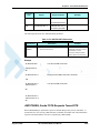
MIPCONF - Configure Internal TCP/IP stack . . . . . . . . . . . . . . . . . . . . . . . . . . . . . . . . . . . 3-412
+MPING, Start Ping Execution (ICMP Protocol) . . . . . . . . . . . . . . . . . . . . . . . . . . . . . . . . 3-414
+MPINGSTAT, Status Update for +MPING Execution . . . . . . . . . . . . . . . . . . . . . . . . . . . 3-418
+MSDNS, Set DNS IP Address . . . . . . . . . . . . . . . . . . . . . . . . . . . . . . . . . . . . . . . . . . . . . . 3-421
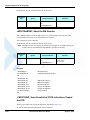
+MIPCSC, Motorola Control Secured Connection . . . . . . . . . . . . . . . . . . . . . . . . . . . . . . . 3-423
+MIPCFF, Control Filtering Feature for Incoming TCP Connection . . . . . . . . . . . . . . . . . 3-426
+MIPSSL, SSL Alerts Unsolicited Report. . . . . . . . . . . . . . . . . . . . . . . . . . . . . . . . . . . . . . 3-428
FTP (File Transfer Protocol) . . . . . . . . . . . . . . . . . . . . . . . . . . . . . . . . . . . . . . . . . . . . . . . . . . . . . 3-431
Session Commands . . . . . . . . . . . . . . . . . . . . . . . . . . . . . . . . . . . . . . . . . . . . . . . . . . . . . . . . . 3-431
+FTPOPEN, Open FTP Connection Between G24 (FTP client) and Remote FTP Server . 3-431
+FTPCLOSE, Close Established FTP Connection Between G24 (FTP client) and Remote FTP
Server . . . . . . . . . . . . . . . . . . . . . . . . . . . . . . . . . . . . . . . . . . . . . . . . . . . . . . . . . . . . . . . . . . 3-433
+FTPINFO, FTP Unsolicited Indication Enable/Disable . . . . . . . . . . . . . . . . . . . . . . . . . . 3-434
+FTPCWD, Change Working Directory . . . . . . . . . . . . . . . . . . . . . . . . . . . . . . . . . . . . . . . 3-435
+FTPMKD, Make Directory . . . . . . . . . . . . . . . . . . . . . . . . . . . . . . . . . . . . . . . . . . . . . . . . 3-437
+FTPRMD, Remove Directory . . . . . . . . . . . . . . . . . . . . . . . . . . . . . . . . . . . . . . . . . . . . . . 3-438
+FTPPWD, Print Working Directory. . . . . . . . . . . . . . . . . . . . . . . . . . . . . . . . . . . . . . . . . . 3-439
+FTPCDUP, Change Directory Up . . . . . . . . . . . . . . . . . . . . . . . . . . . . . . . . . . . . . . . . . . . 3-440
+FTPDEL, Delete File . . . . . . . . . . . . . . . . . . . . . . . . . . . . . . . . . . . . . . . . . . . . . . . . . . . . . 3-440
+FTPREN, Rename File . . . . . . . . . . . . . . . . . . . . . . . . . . . . . . . . . . . . . . . . . . . . . . . . . . . 3-441
+FTPLIST, Request List . . . . . . . . . . . . . . . . . . . . . . . . . . . . . . . . . . . . . . . . . . . . . . . . . . . 3-443
+FTPSTAT, Request Status . . . . . . . . . . . . . . . . . . . . . . . . . . . . . . . . . . . . . . . . . . . . . . . . . 3-444
+FTPSYST, Request Remote FTP Server Operating System Type . . . . . . . . . . . . . . . . . . 3-446
+FTPNOOP, No Operation . . . . . . . . . . . . . . . . . . . . . . . . . . . . . . . . . . . . . . . . . . . . . . . . . 3-447
+FTPSTOR, Store File On Remote FTP Server . . . . . . . . . . . . . . . . . . . . . . . . . . . . . . . . . 3-448
+FTPRETR, Retrieve a File From a Remote FTP Server . . . . . . . . . . . . . . . . . . . . . . . . . . 3-449
NOP - Compatible . . . . . . . . . . . . . . . . . . . . . . . . . . . . . . . . . . . . . . . . . . . . . . . . . . . . . . . . . . . . . 3-451
IGNORED (Compatible Only) Commands . . . . . . . . . . . . . . . . . . . . . . . . . . . . . . . . . . . . . . . 3-451
Fax Class 1. . . . . . . . . . . . . . . . . . . . . . . . . . . . . . . . . . . . . . . . . . . . . . . . . . . . . . . . . . . . . . . . . . . 3-452
Fax Commands . . . . . . . . . . . . . . . . . . . . . . . . . . . . . . . . . . . . . . . . . . . . . . . . . . . . . . . . . . . . 3-453
+FCLASS, Select Mode . . . . . . . . . . . . . . . . . . . . . . . . . . . . . . . . . . . . . . . . . . . . . . . . . . . . 3-453
+FTS, Transmit Silence . . . . . . . . . . . . . . . . . . . . . . . . . . . . . . . . . . . . . . . . . . . . . . . . . . . . 3-454
+FRS, Receive Silence . . . . . . . . . . . . . . . . . . . . . . . . . . . . . . . . . . . . . . . . . . . . . . . . . . . . . 3-454
+FTM, Transmit Data . . . . . . . . . . . . . . . . . . . . . . . . . . . . . . . . . . . . . . . . . . . . . . . . . . . . . 3-455
+FRM, Receive Data . . . . . . . . . . . . . . . . . . . . . . . . . . . . . . . . . . . . . . . . . . . . . . . . . . . . . . 3-457
+FTH, Transmit DATA with HDLC Frame . . . . . . . . . . . . . . . . . . . . . . . . . . . . . . . . . . . . 3-457
+FRH, Receive DATA with HDLC Frame . . . . . . . . . . . . . . . . . . . . . . . . . . . . . . . . . . . . . 3-459
+IFC, Terminal-G24 Local Flow Control . . . . . . . . . . . . . . . . . . . . . . . . . . . . . . . . . . . . . . 3-459
+FPR, Fax Serial Port Rate . . . . . . . . . . . . . . . . . . . . . . . . . . . . . . . . . . . . . . . . . . . . . . . . . 3-461
August 5, 2008
AT Commands Reference Manual
ix
Table of Contents
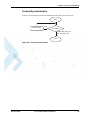
RS232 Multiplexer Feature . . . . . . . . . . . . . . . . . . . . . . . . . . . . . . . . . . . . . . . . . . . . . . . . . . . . . .
MUX Details . . . . . . . . . . . . . . . . . . . . . . . . . . . . . . . . . . . . . . . . . . . . . . . . . . . . . . . . . . . . . .
Protocol Versions . . . . . . . . . . . . . . . . . . . . . . . . . . . . . . . . . . . . . . . . . . . . . . . . . . . . . . . . .
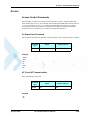
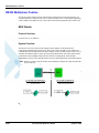
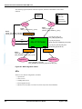
System Overview . . . . . . . . . . . . . . . . . . . . . . . . . . . . . . . . . . . . . . . . . . . . . . . . . . . . . . . . .
Product Architecture . . . . . . . . . . . . . . . . . . . . . . . . . . . . . . . . . . . . . . . . . . . . . . . . . . . . . . .
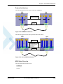
MUX States Overview . . . . . . . . . . . . . . . . . . . . . . . . . . . . . . . . . . . . . . . . . . . . . . . . . . . . .
MUX-Init State . . . . . . . . . . . . . . . . . . . . . . . . . . . . . . . . . . . . . . . . . . . . . . . . . . . . . . . . . . .
MUX State . . . . . . . . . . . . . . . . . . . . . . . . . . . . . . . . . . . . . . . . . . . . . . . . . . . . . . . . . . . . . .
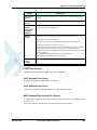
Supported 27.010 Protocol Services. . . . . . . . . . . . . . . . . . . . . . . . . . . . . . . . . . . . . . . . . . .
UART Flow Control . . . . . . . . . . . . . . . . . . . . . . . . . . . . . . . . . . . . . . . . . . . . . . . . . . . . . . .
MUX Software Flow Control Per Channel . . . . . . . . . . . . . . . . . . . . . . . . . . . . . . . . . . . . .
MUX UART Port Speed. . . . . . . . . . . . . . . . . . . . . . . . . . . . . . . . . . . . . . . . . . . . . . . . . . . .
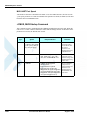
+CMUX, MUX Startup Command . . . . . . . . . . . . . . . . . . . . . . . . . . . . . . . . . . . . . . . . . . . . .
MUX Modes . . . . . . . . . . . . . . . . . . . . . . . . . . . . . . . . . . . . . . . . . . . . . . . . . . . . . . . . . . . . . . .
MUX Customer Open Source Code Packet . . . . . . . . . . . . . . . . . . . . . . . . . . . . . . . . . . . . . . .
APIs . . . . . . . . . . . . . . . . . . . . . . . . . . . . . . . . . . . . . . . . . . . . . . . . . . . . . . . . . . . . . . . . . . . . .
MUX Channels (Information Data Link Control - IDLC) . . . . . . . . . . . . . . . . . . . . . . . . . . . .
Basic MUX Channel Definitions . . . . . . . . . . . . . . . . . . . . . . . . . . . . . . . . . . . . . . . . . . . . .
Channel Priorities . . . . . . . . . . . . . . . . . . . . . . . . . . . . . . . . . . . . . . . . . . . . . . . . . . . . . . . . .
Multiple Channel Configuration. . . . . . . . . . . . . . . . . . . . . . . . . . . . . . . . . . . . . . . . . . . . . .
AT Commands per Channel Configuration . . . . . . . . . . . . . . . . . . . . . . . . . . . . . . . . . . . . .
Multiple Channel Definitions . . . . . . . . . . . . . . . . . . . . . . . . . . . . . . . . . . . . . . . . . . . . . . . .
GPRS Definitions . . . . . . . . . . . . . . . . . . . . . . . . . . . . . . . . . . . . . . . . . . . . . . . . . . . . . . . . .
IDLC Modem Profile in MUX State . . . . . . . . . . . . . . . . . . . . . . . . . . . . . . . . . . . . . . . . . .
Chapter 4:
x
3-463
3-463
3-463
3-463
3-464
3-464
3-465
3-465
3-465
3-466
3-466
3-467
3-467
3-468
3-469
3-469
3-469
3-469
3-469
3-470
3-471
3-483
3-483
3-483
Using the Commands. . . . . . . . . . . . . . . . . . . . . . . . . . . . . . . . . . . . . . . . . . . . . . . . . . . . 4-1
Setting Up the G24 (Power On and Initial Actions) . . . . . . . . . . . . . . . . . . . . . . . . . . . . . . . . . . . . . 4-1
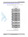
Recommended G24 Initialization after Powerup. . . . . . . . . . . . . . . . . . . . . . . . . . . . . . . . . . . . . . . . 4-3
RS232 Lines Setup . . . . . . . . . . . . . . . . . . . . . . . . . . . . . . . . . . . . . . . . . . . . . . . . . . . . . . . . . . . . 4-4
Test G24 Communication . . . . . . . . . . . . . . . . . . . . . . . . . . . . . . . . . . . . . . . . . . . . . . . . . . . . . . 4-5
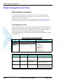
Basic Configuration . . . . . . . . . . . . . . . . . . . . . . . . . . . . . . . . . . . . . . . . . . . . . . . . . . . . . . . . . . . 4-5
SIM Card Status . . . . . . . . . . . . . . . . . . . . . . . . . . . . . . . . . . . . . . . . . . . . . . . . . . . . . . . . . . . . . . 4-7
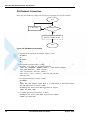
G24 Network Connection . . . . . . . . . . . . . . . . . . . . . . . . . . . . . . . . . . . . . . . . . . . . . . . . . . . . . . . 4-8
Terminal Synchronization . . . . . . . . . . . . . . . . . . . . . . . . . . . . . . . . . . . . . . . . . . . . . . . . . . . . . . 4-9
SMS . . . . . . . . . . . . . . . . . . . . . . . . . . . . . . . . . . . . . . . . . . . . . . . . . . . . . . . . . . . . . . . . . . . . . . . . . 4-10
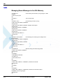
Managing Stored Messages in the G24 Memory . . . . . . . . . . . . . . . . . . . . . . . . . . . . . . . . . . . . 4-10
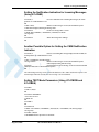
Setting the Notification Indication for Incoming Messages (Using AT+CNMI) . . . . . . . . . . . 4-11
Another Possible Option for Setting the CNMI Notification Indication . . . . . . . . . . . . . . . . . . 4-11
Setting TEXT Mode Parameters (Using AT+CMGW and AT+CMGS) . . . . . . . . . . . . . . . . . . 4-11
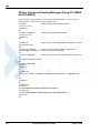
Writing, Saving and Sending Messages (Using AT+CMGW and AT+CMSS) . . . . . . . . . . . . 4-12
Sending Messages (Using AT+CMGS) . . . . . . . . . . . . . . . . . . . . . . . . . . . . . . . . . . . . . . . . . . . 4-13
Deleting Messages (Using AT+CMGD) . . . . . . . . . . . . . . . . . . . . . . . . . . . . . . . . . . . . . . . . . . 4-13
Call Control . . . . . . . . . . . . . . . . . . . . . . . . . . . . . . . . . . . . . . . . . . . . . . . . . . . . . . . . . . . . . . . . . . . 4-14
Dialing Using ATD . . . . . . . . . . . . . . . . . . . . . . . . . . . . . . . . . . . . . . . . . . . . . . . . . . . . . . . . . . 4-14
Direct Dialing from Phone Book . . . . . . . . . . . . . . . . . . . . . . . . . . . . . . . . . . . . . . . . . . . . . . . . 4-15
Dialing the Last Number Example . . . . . . . . . . . . . . . . . . . . . . . . . . . . . . . . . . . . . . . . . . . . . . . 4-16
Voice Call Manipulations . . . . . . . . . . . . . . . . . . . . . . . . . . . . . . . . . . . . . . . . . . . . . . . . . . . . . . 4-16
Call Waiting . . . . . . . . . . . . . . . . . . . . . . . . . . . . . . . . . . . . . . . . . . . . . . . . . . . . . . . . . . . . . . 4-16
Call Forwarding . . . . . . . . . . . . . . . . . . . . . . . . . . . . . . . . . . . . . . . . . . . . . . . . . . . . . . . . . . . 4-16
Conference Call . . . . . . . . . . . . . . . . . . . . . . . . . . . . . . . . . . . . . . . . . . . . . . . . . . . . . . . . . . . 4-17
Data Call . . . . . . . . . . . . . . . . . . . . . . . . . . . . . . . . . . . . . . . . . . . . . . . . . . . . . . . . . . . . . . . . . . . . . 4-18
Switching Modes (Data Mode/Command Mode) . . . . . . . . . . . . . . . . . . . . . . . . . . . . . . . . . . . 4-18
GPRS . . . . . . . . . . . . . . . . . . . . . . . . . . . . . . . . . . . . . . . . . . . . . . . . . . . . . . . . . . . . . . . . . . . . . . . . 4-19
AT Commands Reference Manual
August 5, 2008
Table of Contents
Establishing GPRS PDP Context . . . . . . . . . . . . . . . . . . . . . . . . . . . . . . . . . . . . . . . . . . . . . . . .
Activating a Saved Profile in G24 . . . . . . . . . . . . . . . . . . . . . . . . . . . . . . . . . . . . . . . . . . . . .
Two Ways to Activate PDP Context . . . . . . . . . . . . . . . . . . . . . . . . . . . . . . . . . . . . . . . . . . .
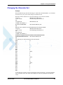
Changing the Character Set . . . . . . . . . . . . . . . . . . . . . . . . . . . . . . . . . . . . . . . . . . . . . . . . . . . . . . .
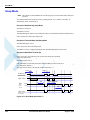
Sleep Mode . . . . . . . . . . . . . . . . . . . . . . . . . . . . . . . . . . . . . . . . . . . . . . . . . . . . . . . . . . . . . . . . . . .
STK . . . . . . . . . . . . . . . . . . . . . . . . . . . . . . . . . . . . . . . . . . . . . . . . . . . . . . . . . . . . . . . . . . . . . . . . .
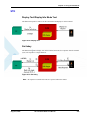
Display Text/Display Idle Mode Text . . . . . . . . . . . . . . . . . . . . . . . . . . . . . . . . . . . . . . . . . . . .
Get Inkey . . . . . . . . . . . . . . . . . . . . . . . . . . . . . . . . . . . . . . . . . . . . . . . . . . . . . . . . . . . . . . . . . .
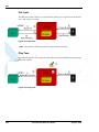
Get Input . . . . . . . . . . . . . . . . . . . . . . . . . . . . . . . . . . . . . . . . . . . . . . . . . . . . . . . . . . . . . . . . . .
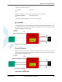
Play Tone . . . . . . . . . . . . . . . . . . . . . . . . . . . . . . . . . . . . . . . . . . . . . . . . . . . . . . . . . . . . . . . . . .
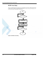
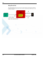
Set Up Menu . . . . . . . . . . . . . . . . . . . . . . . . . . . . . . . . . . . . . . . . . . . . . . . . . . . . . . . . . . . . . . .
Select Item . . . . . . . . . . . . . . . . . . . . . . . . . . . . . . . . . . . . . . . . . . . . . . . . . . . . . . . . . . . . . . . . .
Send SMS . . . . . . . . . . . . . . . . . . . . . . . . . . . . . . . . . . . . . . . . . . . . . . . . . . . . . . . . . . . . . . . . . .
Set Up Call . . . . . . . . . . . . . . . . . . . . . . . . . . . . . . . . . . . . . . . . . . . . . . . . . . . . . . . . . . . . . . . . .
Call Control . . . . . . . . . . . . . . . . . . . . . . . . . . . . . . . . . . . . . . . . . . . . . . . . . . . . . . . . . . . . . . . .
Send DTMF . . . . . . . . . . . . . . . . . . . . . . . . . . . . . . . . . . . . . . . . . . . . . . . . . . . . . . . . . . . . . . . .
Launch Browser . . . . . . . . . . . . . . . . . . . . . . . . . . . . . . . . . . . . . . . . . . . . . . . . . . . . . . . . . . . . .
Setup Event List . . . . . . . . . . . . . . . . . . . . . . . . . . . . . . . . . . . . . . . . . . . . . . . . . . . . . . . . . . . . .
TCP/IP . . . . . . . . . . . . . . . . . . . . . . . . . . . . . . . . . . . . . . . . . . . . . . . . . . . . . . . . . . . . . . . . . . . . . . .
TCP Data Transfer Example . . . . . . . . . . . . . . . . . . . . . . . . . . . . . . . . . . . . . . . . . . . . . . . . . . .
TCP Raw Data Transfer Example (Online Data Mode) . . . . . . . . . . . . . . . . . . . . . . . . . . . . . .
Multi-point Data Transfer Example . . . . . . . . . . . . . . . . . . . . . . . . . . . . . . . . . . . . . . . . . . . . . .
Xoff and Xon Example . . . . . . . . . . . . . . . . . . . . . . . . . . . . . . . . . . . . . . . . . . . . . . . . . . . . . . .
Error in Reopening a Valid Socket . . . . . . . . . . . . . . . . . . . . . . . . . . . . . . . . . . . . . . . . . . . . . .
Audio . . . . . . . . . . . . . . . . . . . . . . . . . . . . . . . . . . . . . . . . . . . . . . . . . . . . . . . . . . . . . . . . . . . . . . . .
Scenarios for Setting Up Handset Mode or Handsfree Mode . . . . . . . . . . . . . . . . . . . . . . . . . .
Handset Mode. . . . . . . . . . . . . . . . . . . . . . . . . . . . . . . . . . . . . . . . . . . . . . . . . . . . . . . . . . . . .
Handsfree Mode . . . . . . . . . . . . . . . . . . . . . . . . . . . . . . . . . . . . . . . . . . . . . . . . . . . . . . . . . . .
Firmware Update Over the Air (FOTA) . . . . . . . . . . . . . . . . . . . . . . . . . . . . . . . . . . . . . . . . . . . . .
FOTA Command for Non-Automatic Mode (Non-Transparent Mode) . . . . . . . . . . . . . . . . . .
FOTA Command for Automatic Mode (Transparent Mode) . . . . . . . . . . . . . . . . . . . . . . . . . .
Chapter 5:
4-19
4-19
4-19
4-21
4-22
4-23
4-23
4-23
4-24
4-24
4-25
4-25
4-25
4-26
4-26
4-27
4-27
4-28
4-29
4-29
4-29
4-30
4-31
4-32
4-33
4-33
4-33
4-33
4-34
4-34
4-35
Tools . . . . . . . . . . . . . . . . . . . . . . . . . . . . . . . . . . . . . . . . . . . . . . . . . . . . . . . . . . . . . . . . . .5-1
Tools Overview . . . . . . . . . . . . . . . . . . . . . . . . . . . . . . . . . . . . . . . . . . . . . . . . . . . . . . . . . . . . . . . . . 5-1
PC Driver. . . . . . . . . . . . . . . . . . . . . . . . . . . . . . . . . . . . . . . . . . . . . . . . . . . . . . . . . . . . . . . . . . . . . . 5-1
Overview . . . . . . . . . . . . . . . . . . . . . . . . . . . . . . . . . . . . . . . . . . . . . . . . . . . . . . . . . . . . . . . . . . . 5-1
Fax Communication by Standard 19200 bps Modem . . . . . . . . . . . . . . . . . . . . . . . . . . . . . . . . . 5-1
Using WinFAX . . . . . . . . . . . . . . . . . . . . . . . . . . . . . . . . . . . . . . . . . . . . . . . . . . . . . . . . . . . . . . 5-2
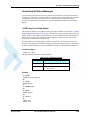
Establishing GPRS PDP Context (Using GPRS Manager) . . . . . . . . . . . . . . . . . . . . . . . . . . . . . 5-2
Installing GPRS Manager on a PC . . . . . . . . . . . . . . . . . . . . . . . . . . . . . . . . . . . . . . . . . . . . . . 5-2
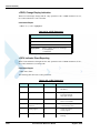
Configuring a Dialer Icon. . . . . . . . . . . . . . . . . . . . . . . . . . . . . . . . . . . . . . . . . . . . . . . . . . . . . 5-2
Establishing a Connection . . . . . . . . . . . . . . . . . . . . . . . . . . . . . . . . . . . . . . . . . . . . . . . . . . . . 5-2
Appendix A: Reference Tables . . . . . . . . . . . . . . . . . . . . . . . . . . . . . . . . . . . . . . . . . . . . . . . . . . . . . A-1
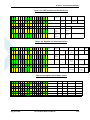
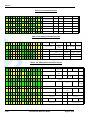
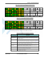
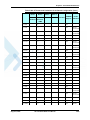
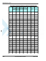
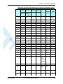
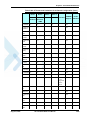
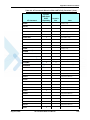
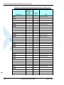
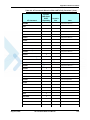
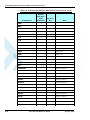
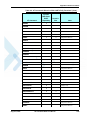
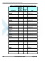
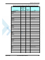
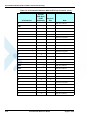
AT Commands Alphabetical Summary. . . . . . . . . . . . . . . . . . . . . . . . . . . . . . . . . . . . . . . . . . . . . . . A-1
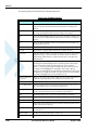
AT Commands Behaviour When UART 2 Has Full Functionality. . . . . . . . . . . . . . . . . . . . . . . . . A-23
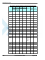
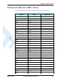
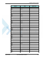
Character Set Table CS1: (GSM -> UCS-2) . . . . . . . . . . . . . . . . . . . . . . . . . . . . . . . . . . . . . . . . . . A-33
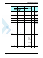
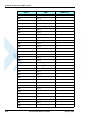
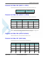
Character Set Table CS2: (ASCII <-> UTF-8) . . . . . . . . . . . . . . . . . . . . . . . . . . . . . . . . . . . . . . . . A-37
Character Set Table CS3: (UCS-2 <-> UTF-8) . . . . . . . . . . . . . . . . . . . . . . . . . . . . . . . . . . . . . . . . A-37
Character Set Table CS6: (UCS-2 Full table) . . . . . . . . . . . . . . . . . . . . . . . . . . . . . . . . . . . . . . . . . A-37
Character Set Table CS7: (ASCII table) . . . . . . . . . . . . . . . . . . . . . . . . . . . . . . . . . . . . . . . . . . . . . A-37
Appendix B: MUX . . . . . . . . . . . . . . . . . . . . . . . . . . . . . . . . . . . . . . . . . . . . . . . . . . . . . . . . . . . . . . . . B-1
PREMUX State . . . . . . . . . . . . . . . . . . . . . . . . . . . . . . . . . . . . . . . . . . . . . . . . . . . . . . . . . . . . . . . . . B-1
August 5, 2008
AT Commands Reference Manual
xi
Table of Contents
MUX-Init State . . . . . . . . . . . . . . . . . . . . . . . . . . . . . . . . . . . . . . . . . . . . . . . . . . . . . . . . . . . . . . . . . B-1
MUX State . . . . . . . . . . . . . . . . . . . . . . . . . . . . . . . . . . . . . . . . . . . . . . . . . . . . . . . . . . . . . . . . . . . . . B-2
Software Procedures Related to RS232 HW Lines . . . . . . . . . . . . . . . . . . . . . . . . . . . . . . . . . . . . . . B-2
RI Hardware Line . . . . . . . . . . . . . . . . . . . . . . . . . . . . . . . . . . . . . . . . . . . . . . . . . . . . . . . . . . . . . B-2
DCD Hardware Line . . . . . . . . . . . . . . . . . . . . . . . . . . . . . . . . . . . . . . . . . . . . . . . . . . . . . . . . . . B-2
DTR Hardware Line . . . . . . . . . . . . . . . . . . . . . . . . . . . . . . . . . . . . . . . . . . . . . . . . . . . . . . . . . . . B-2
G24 DTR Interrupt . . . . . . . . . . . . . . . . . . . . . . . . . . . . . . . . . . . . . . . . . . . . . . . . . . . . . . . . . . . . B-2
DSR Hardware Line (Optional) . . . . . . . . . . . . . . . . . . . . . . . . . . . . . . . . . . . . . . . . . . . . . . . . . . B-2
MUX UART Port Speed . . . . . . . . . . . . . . . . . . . . . . . . . . . . . . . . . . . . . . . . . . . . . . . . . . . . . . . B-3
Controlling the UART Port Speed Within MUX State . . . . . . . . . . . . . . . . . . . . . . . . . . . . . . . . B-3
Basic Mode UART Software Flow Control . . . . . . . . . . . . . . . . . . . . . . . . . . . . . . . . . . . . . . . . . B-3
Advanced Mode UART Software Flow Control . . . . . . . . . . . . . . . . . . . . . . . . . . . . . . . . . . . . . B-3
Basic Mode MUX Software Flow Control Per Channel . . . . . . . . . . . . . . . . . . . . . . . . . . . . . . . B-3
Advanced Mode MUX Software Flow Control Per Channel . . . . . . . . . . . . . . . . . . . . . . . . . . . . B-4
MUX Modes . . . . . . . . . . . . . . . . . . . . . . . . . . . . . . . . . . . . . . . . . . . . . . . . . . . . . . . . . . . . . . . . . B-4
Advance Mode Transparency Mechanism . . . . . . . . . . . . . . . . . . . . . . . . . . . . . . . . . . . . . . . . B-4
Advance Mode Frame Packing. . . . . . . . . . . . . . . . . . . . . . . . . . . . . . . . . . . . . . . . . . . . . . . . . B-5
Advance Mode Frame Unpacking . . . . . . . . . . . . . . . . . . . . . . . . . . . . . . . . . . . . . . . . . . . . . . B-5
MUX State Procedures . . . . . . . . . . . . . . . . . . . . . . . . . . . . . . . . . . . . . . . . . . . . . . . . . . . . . . . . . B-5
UIH Frames . . . . . . . . . . . . . . . . . . . . . . . . . . . . . . . . . . . . . . . . . . . . . . . . . . . . . . . . . . . . . . . B-6
Test UIH Control Frames . . . . . . . . . . . . . . . . . . . . . . . . . . . . . . . . . . . . . . . . . . . . . . . . . . . . . B-6
MSC UIH Control Frame – Virtual Channel V.24 signals. . . . . . . . . . . . . . . . . . . . . . . . . . . . B-6
MUX Customer Packet . . . . . . . . . . . . . . . . . . . . . . . . . . . . . . . . . . . . . . . . . . . . . . . . . . . . . . . . B-7
MUX Customer Open Source Code Packet . . . . . . . . . . . . . . . . . . . . . . . . . . . . . . . . . . . . . . . B-7
APIs . . . . . . . . . . . . . . . . . . . . . . . . . . . . . . . . . . . . . . . . . . . . . . . . . . . . . . . . . . . . . . . . . . . . . B-8
MUX Open Service . . . . . . . . . . . . . . . . . . . . . . . . . . . . . . . . . . . . . . . . . . . . . . . . . . . . . . . . B-10
MUX Close Service . . . . . . . . . . . . . . . . . . . . . . . . . . . . . . . . . . . . . . . . . . . . . . . . . . . . . . . . B-10
Data Transfer . . . . . . . . . . . . . . . . . . . . . . . . . . . . . . . . . . . . . . . . . . . . . . . . . . . . . . . . . . . . . B-10
Acronyms and Abbreviations
Index
xii
AT Commands Reference Manual
August 5, 2008
List of Figures
1-1
1-2
1-3
1-4
1-5
1-6
1-7
System Overview . . . . . . . . . . . . . . . . . . . . . . . . . . . . . . . . . . . . . . . . . . . . . . . . . . . . . . . . . . . 1-5
G24 Operation Modes Switching . . . . . . . . . . . . . . . . . . . . . . . . . . . . . . . . . . . . . . . . . . . . . . 1-12
Files Transfer Process. . . . . . . . . . . . . . . . . . . . . . . . . . . . . . . . . . . . . . . . . . . . . . . . . . . . . . . 1-13
Sidetone . . . . . . . . . . . . . . . . . . . . . . . . . . . . . . . . . . . . . . . . . . . . . . . . . . . . . . . . . . . . . . . . . 1-14
Echo Suppression . . . . . . . . . . . . . . . . . . . . . . . . . . . . . . . . . . . . . . . . . . . . . . . . . . . . . . . . . . 1-15
G24 with Multiplexer Support Capabilities . . . . . . . . . . . . . . . . . . . . . . . . . . . . . . . . . . . . . . 1-16
Email Server Connection Overview . . . . . . . . . . . . . . . . . . . . . . . . . . . . . . . . . . . . . . . . . . . . 1-20
2-1
2-2
2-3
2-4
3-1
3-2
3-3
3-4
3-5
3-6
3-7
3-8
3-9
3-10
3-11
3-12
3-13
3-14
3-15
3-16
3-17
3-18
3-19
3-20
3-21
3-22
3-23
AT Commands Protocol . . . . . . . . . . . . . . . . . . . . . . . . . . . . . . . . . . . . . . . . . . . . . . . . . . . . . . 2-2
Basic Structure of a Command Line. . . . . . . . . . . . . . . . . . . . . . . . . . . . . . . . . . . . . . . . . . . . . 2-3
Response to a Command Line . . . . . . . . . . . . . . . . . . . . . . . . . . . . . . . . . . . . . . . . . . . . . . . . . 2-4
Flow and Structure Configuration Commands . . . . . . . . . . . . . . . . . . . . . . . . . . . . . . . . . . . . . 2-5
TTY Hardware Configuration . . . . . . . . . . . . . . . . . . . . . . . . . . . . . . . . . . . . . . . . . . . . . . . . 3-45
Temperature Vs. A/D Value . . . . . . . . . . . . . . . . . . . . . . . . . . . . . . . . . . . . . . . . . . . . . . . . . 3-230
Audio Modes . . . . . . . . . . . . . . . . . . . . . . . . . . . . . . . . . . . . . . . . . . . . . . . . . . . . . . . . . . . . 3-236
Basic Audio Setup . . . . . . . . . . . . . . . . . . . . . . . . . . . . . . . . . . . . . . . . . . . . . . . . . . . . . . . . 3-237
Advanced Audio Setup . . . . . . . . . . . . . . . . . . . . . . . . . . . . . . . . . . . . . . . . . . . . . . . . . . . . . 3-237
Analog/Digital Switching . . . . . . . . . . . . . . . . . . . . . . . . . . . . . . . . . . . . . . . . . . . . . . . . . . . 3-238
Audio Paths. . . . . . . . . . . . . . . . . . . . . . . . . . . . . . . . . . . . . . . . . . . . . . . . . . . . . . . . . . . . . . 3-244
G24 Audio Gain . . . . . . . . . . . . . . . . . . . . . . . . . . . . . . . . . . . . . . . . . . . . . . . . . . . . . . . . . . 3-246
SIM States. . . . . . . . . . . . . . . . . . . . . . . . . . . . . . . . . . . . . . . . . . . . . . . . . . . . . . . . . . . . . . . 3-259
Wakeup-In Line . . . . . . . . . . . . . . . . . . . . . . . . . . . . . . . . . . . . . . . . . . . . . . . . . . . . . . . . . . 3-292
Wake up Outline . . . . . . . . . . . . . . . . . . . . . . . . . . . . . . . . . . . . . . . . . . . . . . . . . . . . . . . . . . 3-292
Sleep Mode when S24 > 0 . . . . . . . . . . . . . . . . . . . . . . . . . . . . . . . . . . . . . . . . . . . . . . . . . . 3-293
G24 Lines when S24 > 0 . . . . . . . . . . . . . . . . . . . . . . . . . . . . . . . . . . . . . . . . . . . . . . . . . . . 3-293
SIM Toolkit . . . . . . . . . . . . . . . . . . . . . . . . . . . . . . . . . . . . . . . . . . . . . . . . . . . . . . . . . . . . . 3-365
Communication During DTMF Command . . . . . . . . . . . . . . . . . . . . . . . . . . . . . . . . . . . . . 3-383
Communication During Launch Browser Command . . . . . . . . . . . . . . . . . . . . . . . . . . . . . . 3-384
G24 with and without MUX . . . . . . . . . . . . . . . . . . . . . . . . . . . . . . . . . . . . . . . . . . . . . . . . . 3-463
PREMUX Architecture. . . . . . . . . . . . . . . . . . . . . . . . . . . . . . . . . . . . . . . . . . . . . . . . . . . . . 3-464
Current MUX Architecture. . . . . . . . . . . . . . . . . . . . . . . . . . . . . . . . . . . . . . . . . . . . . . . . . . 3-464
MUX States . . . . . . . . . . . . . . . . . . . . . . . . . . . . . . . . . . . . . . . . . . . . . . . . . . . . . . . . . . . . . 3-465
Two-channel Configuration . . . . . . . . . . . . . . . . . . . . . . . . . . . . . . . . . . . . . . . . . . . . . . . . . 3-470
Four-Channel Configuration. . . . . . . . . . . . . . . . . . . . . . . . . . . . . . . . . . . . . . . . . . . . . . . . . 3-470
Using the Additional UART. . . . . . . . . . . . . . . . . . . . . . . . . . . . . . . . . . . . . . . . . . . . . . . . . 3-471
4-1
4-2
4-3
4-4
4-5
4-6
4-7
4-8
4-9
4-10
Phone State Transactions . . . . . . . . . . . . . . . . . . . . . . . . . . . . . . . . . . . . . . . . . . . . . . . . . . . . . 4-1
Detailed Phone State Transactions . . . . . . . . . . . . . . . . . . . . . . . . . . . . . . . . . . . . . . . . . . . . . . 4-2
Recommended G24 Initialization Workflow . . . . . . . . . . . . . . . . . . . . . . . . . . . . . . . . . . . . . . 4-3
RS232 Lines Setup . . . . . . . . . . . . . . . . . . . . . . . . . . . . . . . . . . . . . . . . . . . . . . . . . . . . . . . . . . 4-4
Test G24 Communication. . . . . . . . . . . . . . . . . . . . . . . . . . . . . . . . . . . . . . . . . . . . . . . . . . . . . 4-5
Basic Configuration . . . . . . . . . . . . . . . . . . . . . . . . . . . . . . . . . . . . . . . . . . . . . . . . . . . . . . . . . 4-5
SIM Card Status . . . . . . . . . . . . . . . . . . . . . . . . . . . . . . . . . . . . . . . . . . . . . . . . . . . . . . . . . . . . 4-7
G24 Network Connection . . . . . . . . . . . . . . . . . . . . . . . . . . . . . . . . . . . . . . . . . . . . . . . . . . . . . 4-8
Terminal Synchronization . . . . . . . . . . . . . . . . . . . . . . . . . . . . . . . . . . . . . . . . . . . . . . . . . . . . 4-9
Call States . . . . . . . . . . . . . . . . . . . . . . . . . . . . . . . . . . . . . . . . . . . . . . . . . . . . . . . . . . . . . . . . 4-14
August 5, 2008
AT Commands Reference Manual
xiii
List of Figures
xiv
4-11
4-12
4-13
4-14
4-15
4-16
4-17
4-18
4-19
4-20
4-21
4-22
4-23
4-24
Sleep Mode when S24 > 0 . . . . . . . . . . . . . . . . . . . . . . . . . . . . . . . . . . . . . . . . . . . . . . . . . . .4-22
Display Text . . . . . . . . . . . . . . . . . . . . . . . . . . . . . . . . . . . . . . . . . . . . . . . . . . . . . . . . . . . . . .4-23
Get Inkey. . . . . . . . . . . . . . . . . . . . . . . . . . . . . . . . . . . . . . . . . . . . . . . . . . . . . . . . . . . . . . . . .4-23
Get Input . . . . . . . . . . . . . . . . . . . . . . . . . . . . . . . . . . . . . . . . . . . . . . . . . . . . . . . . . . . . . . . . .4-24
Play Tone . . . . . . . . . . . . . . . . . . . . . . . . . . . . . . . . . . . . . . . . . . . . . . . . . . . . . . . . . . . . . . . .4-24
Set Up Menu . . . . . . . . . . . . . . . . . . . . . . . . . . . . . . . . . . . . . . . . . . . . . . . . . . . . . . . . . . . . . .4-25
Select Item. . . . . . . . . . . . . . . . . . . . . . . . . . . . . . . . . . . . . . . . . . . . . . . . . . . . . . . . . . . . . . . .4-25
Send SMS . . . . . . . . . . . . . . . . . . . . . . . . . . . . . . . . . . . . . . . . . . . . . . . . . . . . . . . . . . . . . . . .4-25
Set Up Call . . . . . . . . . . . . . . . . . . . . . . . . . . . . . . . . . . . . . . . . . . . . . . . . . . . . . . . . . . . . . . .4-26
Call Control. . . . . . . . . . . . . . . . . . . . . . . . . . . . . . . . . . . . . . . . . . . . . . . . . . . . . . . . . . . . . . .4-26
Send DTMF. . . . . . . . . . . . . . . . . . . . . . . . . . . . . . . . . . . . . . . . . . . . . . . . . . . . . . . . . . . . . . .4-27
Launch Browser . . . . . . . . . . . . . . . . . . . . . . . . . . . . . . . . . . . . . . . . . . . . . . . . . . . . . . . . . . .4-27
Setup Event List . . . . . . . . . . . . . . . . . . . . . . . . . . . . . . . . . . . . . . . . . . . . . . . . . . . . . . . . . . .4-28
Handset or Handsfree Setup . . . . . . . . . . . . . . . . . . . . . . . . . . . . . . . . . . . . . . . . . . . . . . . . . .4-33
B-1
MUX Integration Packet . . . . . . . . . . . . . . . . . . . . . . . . . . . . . . . . . . . . . . . . . . . . . . . . . . . . . B-8
AT Commands Reference Manual
August 5, 2008
List of Tables
1-1
AT Commands . . . . . . . . . . . . . . . . . . . . . . . . . . . . . . . . . . . . . . . . . . . . . . . . . . . . . . . . . . . . 1-24
2-1
Core AT Commands . . . . . . . . . . . . . . . . . . . . . . . . . . . . . . . . . . . . . . . . . . . . . . . . . . . . . . . . . 2-9
3-1
3-2
3-3
3-4
3-5
3-6
3-7
3-8
3-9
3-10
3-11
3-12
3-13
3-14
3-15
3-16
3-17
3-18
3-19
3-20
3-21
3-22
3-23
3-24
3-25
3-26
3-27
3-28
3-29
3-30
3-31
3-32
3-33
3-34
3-35
3-36
3-37
3-38
3-39
3-40
3-41
3-42
+CGSN, +GSN Parameters . . . . . . . . . . . . . . . . . . . . . . . . . . . . . . . . . . . . . . . . . . . . . . . . . . . 3-4
+CSCS Parameters . . . . . . . . . . . . . . . . . . . . . . . . . . . . . . . . . . . . . . . . . . . . . . . . . . . . . . . . . . 3-5
+CNUM Parameters . . . . . . . . . . . . . . . . . . . . . . . . . . . . . . . . . . . . . . . . . . . . . . . . . . . . . . . . . 3-8
D Parameters. . . . . . . . . . . . . . . . . . . . . . . . . . . . . . . . . . . . . . . . . . . . . . . . . . . . . . . . . . . . . . 3-14
D> Parameters . . . . . . . . . . . . . . . . . . . . . . . . . . . . . . . . . . . . . . . . . . . . . . . . . . . . . . . . . . . . 3-15
DL Parameters . . . . . . . . . . . . . . . . . . . . . . . . . . . . . . . . . . . . . . . . . . . . . . . . . . . . . . . . . . . . 3-16
+CRC Parameters . . . . . . . . . . . . . . . . . . . . . . . . . . . . . . . . . . . . . . . . . . . . . . . . . . . . . . . . . . 3-20
+CLIP Parameters. . . . . . . . . . . . . . . . . . . . . . . . . . . . . . . . . . . . . . . . . . . . . . . . . . . . . . . . . . 3-22
+CCWA Parameters . . . . . . . . . . . . . . . . . . . . . . . . . . . . . . . . . . . . . . . . . . . . . . . . . . . . . . . . 3-24
+CHLD Parameters . . . . . . . . . . . . . . . . . . . . . . . . . . . . . . . . . . . . . . . . . . . . . . . . . . . . . . . . 3-26
+CHLD Actions According to Call State and Operation . . . . . . . . . . . . . . . . . . . . . . . . . . . . 3-27
+CCFC Parameters . . . . . . . . . . . . . . . . . . . . . . . . . . . . . . . . . . . . . . . . . . . . . . . . . . . . . . . . . 3-30
+CLIR Parameters . . . . . . . . . . . . . . . . . . . . . . . . . . . . . . . . . . . . . . . . . . . . . . . . . . . . . . . . . 3-32
+CBST Parameters . . . . . . . . . . . . . . . . . . . . . . . . . . . . . . . . . . . . . . . . . . . . . . . . . . . . . . . . . 3-34
+CSNS Parameters . . . . . . . . . . . . . . . . . . . . . . . . . . . . . . . . . . . . . . . . . . . . . . . . . . . . . . . . . 3-37
Mapping Table (V.34) . . . . . . . . . . . . . . . . . . . . . . . . . . . . . . . . . . . . . . . . . . . . . . . . . . . . . . 3-38
+MFIC Parameters . . . . . . . . . . . . . . . . . . . . . . . . . . . . . . . . . . . . . . . . . . . . . . . . . . . . . . . . . 3-41
+MHUP Parameters . . . . . . . . . . . . . . . . . . . . . . . . . . . . . . . . . . . . . . . . . . . . . . . . . . . . . . . . 3-42
+MVC Parameters . . . . . . . . . . . . . . . . . . . . . . . . . . . . . . . . . . . . . . . . . . . . . . . . . . . . . . . . . 3-43
+MTTY Parameters . . . . . . . . . . . . . . . . . . . . . . . . . . . . . . . . . . . . . . . . . . . . . . . . . . . . . . . . 3-45
+CPAS Parameters . . . . . . . . . . . . . . . . . . . . . . . . . . . . . . . . . . . . . . . . . . . . . . . . . . . . . . . . . 3-46
+CLCC Parameters. . . . . . . . . . . . . . . . . . . . . . . . . . . . . . . . . . . . . . . . . . . . . . . . . . . . . . . . . 3-48
+MCST Parameters . . . . . . . . . . . . . . . . . . . . . . . . . . . . . . . . . . . . . . . . . . . . . . . . . . . . . . . . 3-50
+TCLCC Parameters . . . . . . . . . . . . . . . . . . . . . . . . . . . . . . . . . . . . . . . . . . . . . . . . . . . . . . . 3-52
+MNTFY Parameters . . . . . . . . . . . . . . . . . . . . . . . . . . . . . . . . . . . . . . . . . . . . . . . . . . . . . . . 3-54
+CAOC Parameters . . . . . . . . . . . . . . . . . . . . . . . . . . . . . . . . . . . . . . . . . . . . . . . . . . . . . . . . 3-56
+CACM Parameters . . . . . . . . . . . . . . . . . . . . . . . . . . . . . . . . . . . . . . . . . . . . . . . . . . . . . . . . 3-58
+CAMM Parameters. . . . . . . . . . . . . . . . . . . . . . . . . . . . . . . . . . . . . . . . . . . . . . . . . . . . . . . . 3-59
+CPUC Parameters. . . . . . . . . . . . . . . . . . . . . . . . . . . . . . . . . . . . . . . . . . . . . . . . . . . . . . . . . 3-60
+CR Parameters . . . . . . . . . . . . . . . . . . . . . . . . . . . . . . . . . . . . . . . . . . . . . . . . . . . . . . . . . . . 3-61
+CSSN Parameters . . . . . . . . . . . . . . . . . . . . . . . . . . . . . . . . . . . . . . . . . . . . . . . . . . . . . . . . . 3-63
+CSSI Notification Values . . . . . . . . . . . . . . . . . . . . . . . . . . . . . . . . . . . . . . . . . . . . . . . . . . . 3-63
+CSSU Notification Values . . . . . . . . . . . . . . . . . . . . . . . . . . . . . . . . . . . . . . . . . . . . . . . . . . 3-63
+CUSD Parameters. . . . . . . . . . . . . . . . . . . . . . . . . . . . . . . . . . . . . . . . . . . . . . . . . . . . . . . . . 3-65
CUSD Termination Cause Table Index . . . . . . . . . . . . . . . . . . . . . . . . . . . . . . . . . . . . . . . . . 3-67
+COLP Parameters . . . . . . . . . . . . . . . . . . . . . . . . . . . . . . . . . . . . . . . . . . . . . . . . . . . . . . . . . 3-70
+CPBS Parameters . . . . . . . . . . . . . . . . . . . . . . . . . . . . . . . . . . . . . . . . . . . . . . . . . . . . . . . . . 3-72
+CPBR Parameters . . . . . . . . . . . . . . . . . . . . . . . . . . . . . . . . . . . . . . . . . . . . . . . . . . . . . . . . . 3-74
+CPBF Parameters . . . . . . . . . . . . . . . . . . . . . . . . . . . . . . . . . . . . . . . . . . . . . . . . . . . . . . . . . 3-75
+CPBW Parameters . . . . . . . . . . . . . . . . . . . . . . . . . . . . . . . . . . . . . . . . . . . . . . . . . . . . . . . . 3-77
+CSVM Parameters . . . . . . . . . . . . . . . . . . . . . . . . . . . . . . . . . . . . . . . . . . . . . . . . . . . . . . . . 3-78
+MDSI Parameters . . . . . . . . . . . . . . . . . . . . . . . . . . . . . . . . . . . . . . . . . . . . . . . . . . . . . . . . . 3-80
August 5, 2008
AT Commands Reference Manual
xv
List of Tables
3-43
3-44
3-45
3-46
3-47
3-48
3-49
3-50
3-51
3-52
3-53
3-54
3-55
3-56
3-57
3-58
3-59
3-60
3-61
3-62
3-63
3-64
3-65
3-66
3-67
3-68
3-69
3-70
3-71
3-72
3-73
3-74
3-75
3-76
3-77
3-78
3-79
3-80
3-81
3-82
3-83
3-84
3-85
3-86
3-87
3-88
3-89
3-90
3-91
3-92
3-93
3-94
3-95
3-96
xvi
+MCSN Parameters . . . . . . . . . . . . . . . . . . . . . . . . . . . . . . . . . . . . . . . . . . . . . . . . . . . . . . . .3-83
+MPDPM Parameters . . . . . . . . . . . . . . . . . . . . . . . . . . . . . . . . . . . . . . . . . . . . . . . . . . . . . . .3-85
+MALARM Parameters . . . . . . . . . . . . . . . . . . . . . . . . . . . . . . . . . . . . . . . . . . . . . . . . . . . . .3-86
+MDBGD Parameters. . . . . . . . . . . . . . . . . . . . . . . . . . . . . . . . . . . . . . . . . . . . . . . . . . . . . . .3-89
+MDBR Parameters . . . . . . . . . . . . . . . . . . . . . . . . . . . . . . . . . . . . . . . . . . . . . . . . . . . . . . . .3-90
+MDBW Parameters. . . . . . . . . . . . . . . . . . . . . . . . . . . . . . . . . . . . . . . . . . . . . . . . . . . . . . . .3-92
+MDBWE Parameters . . . . . . . . . . . . . . . . . . . . . . . . . . . . . . . . . . . . . . . . . . . . . . . . . . . . . .3-94
+CCLK Parameters . . . . . . . . . . . . . . . . . . . . . . . . . . . . . . . . . . . . . . . . . . . . . . . . . . . . . . . . .3-97
+CSMS Parameters . . . . . . . . . . . . . . . . . . . . . . . . . . . . . . . . . . . . . . . . . . . . . . . . . . . . . . . . .3-98
+CPMS Parameters . . . . . . . . . . . . . . . . . . . . . . . . . . . . . . . . . . . . . . . . . . . . . . . . . . . . . . . .3-100
+CMGF Parameters . . . . . . . . . . . . . . . . . . . . . . . . . . . . . . . . . . . . . . . . . . . . . . . . . . . . . . .3-101
+CSCA Input Characters and Hexadecimal Values . . . . . . . . . . . . . . . . . . . . . . . . . . . . . . .3-102
+CSCA Parameters . . . . . . . . . . . . . . . . . . . . . . . . . . . . . . . . . . . . . . . . . . . . . . . . . . . . . . . .3-103
+CSMP Parameters . . . . . . . . . . . . . . . . . . . . . . . . . . . . . . . . . . . . . . . . . . . . . . . . . . . . . . . .3-104
VP Relative Format (In Integer Frmat). . . . . . . . . . . . . . . . . . . . . . . . . . . . . . . . . . . . . . . . .3-105
+CSDH Parameters . . . . . . . . . . . . . . . . . . . . . . . . . . . . . . . . . . . . . . . . . . . . . . . . . . . . . . . .3-106
+CNMI Parameters . . . . . . . . . . . . . . . . . . . . . . . . . . . . . . . . . . . . . . . . . . . . . . . . . . . . . . . .3-107
+CMTI Parameters . . . . . . . . . . . . . . . . . . . . . . . . . . . . . . . . . . . . . . . . . . . . . . . . . . . . . . . .3-110
+CMT Parameters . . . . . . . . . . . . . . . . . . . . . . . . . . . . . . . . . . . . . . . . . . . . . . . . . . . . . . . . .3-111
+CBM Parameters. . . . . . . . . . . . . . . . . . . . . . . . . . . . . . . . . . . . . . . . . . . . . . . . . . . . . . . . .3-112
+CDSI Parameters. . . . . . . . . . . . . . . . . . . . . . . . . . . . . . . . . . . . . . . . . . . . . . . . . . . . . . . . .3-113
+CDS Parameters . . . . . . . . . . . . . . . . . . . . . . . . . . . . . . . . . . . . . . . . . . . . . . . . . . . . . . . . .3-114
+CGML/+MMGL Parameters . . . . . . . . . . . . . . . . . . . . . . . . . . . . . . . . . . . . . . . . . . . . . . .3-116
+CGMR/+MMGR Parameters . . . . . . . . . . . . . . . . . . . . . . . . . . . . . . . . . . . . . . . . . . . . . . .3-119
Layout of SMS-DELIVER in PDU Mode (according to GSM03.40) . . . . . . . . . . . . . . . . .3-120
<fo> for SMS-DELIVER Message. . . . . . . . . . . . . . . . . . . . . . . . . . . . . . . . . . . . . . . . . . . .3-121
Layout of SMS-STATUS-REPORT in PDU Mode (according to GSM03.40) . . . . . . . . . .3-121
<fo> for SMS-STATUS-REPORT Message . . . . . . . . . . . . . . . . . . . . . . . . . . . . . . . . . . . .3-123
<TP-PI> for SMS-STATUS-REPORT Message . . . . . . . . . . . . . . . . . . . . . . . . . . . . . . . . .3-123
+MMAR Parameters . . . . . . . . . . . . . . . . . . . . . . . . . . . . . . . . . . . . . . . . . . . . . . . . . . . . . . .3-125
+CMSS Parameters . . . . . . . . . . . . . . . . . . . . . . . . . . . . . . . . . . . . . . . . . . . . . . . . . . . . . . . .3-126
+CMGW Parameters. . . . . . . . . . . . . . . . . . . . . . . . . . . . . . . . . . . . . . . . . . . . . . . . . . . . . . .3-127
Layout of SMS-SUBMIT in PDU Mode: (according to GSM03.40). . . . . . . . . . . . . . . . . .3-128
Layout of SMS-COMMAND in PDU Mode: (according to GSM03.40). . . . . . . . . . . . . . .3-128
<fo> for SMS-SUBMIT Message. . . . . . . . . . . . . . . . . . . . . . . . . . . . . . . . . . . . . . . . . . . . .3-129
<fo> for SMS-COMMAND Message. . . . . . . . . . . . . . . . . . . . . . . . . . . . . . . . . . . . . . . . . .3-130
+CMGD Parameters . . . . . . . . . . . . . . . . . . . . . . . . . . . . . . . . . . . . . . . . . . . . . . . . . . . . . . .3-132
+CGSMS Parameters . . . . . . . . . . . . . . . . . . . . . . . . . . . . . . . . . . . . . . . . . . . . . . . . . . . . . .3-133
+CMGS Parameters . . . . . . . . . . . . . . . . . . . . . . . . . . . . . . . . . . . . . . . . . . . . . . . . . . . . . . .3-134
+CSCB Parameters . . . . . . . . . . . . . . . . . . . . . . . . . . . . . . . . . . . . . . . . . . . . . . . . . . . . . . . .3-136
+MCSAT Parameters . . . . . . . . . . . . . . . . . . . . . . . . . . . . . . . . . . . . . . . . . . . . . . . . . . . . . .3-138
+MEDT Parameters . . . . . . . . . . . . . . . . . . . . . . . . . . . . . . . . . . . . . . . . . . . . . . . . . . . . . . .3-141
+TSMSRET Parameters . . . . . . . . . . . . . . . . . . . . . . . . . . . . . . . . . . . . . . . . . . . . . . . . . . . .3-143
+MRICS Parameters . . . . . . . . . . . . . . . . . . . . . . . . . . . . . . . . . . . . . . . . . . . . . . . . . . . . . . .3-144
<dcs> field and +CSCS settings conversion when writing SM . . . . . . . . . . . . . . . . . . . . . .3-146
<dcs> field and +CSCS settings conversion when reading SM . . . . . . . . . . . . . . . . . . . . . .3-147
+MEMISP Parameters . . . . . . . . . . . . . . . . . . . . . . . . . . . . . . . . . . . . . . . . . . . . . . . . . . . . .3-150
+MEMAS Parameters . . . . . . . . . . . . . . . . . . . . . . . . . . . . . . . . . . . . . . . . . . . . . . . . . . . . . .3-152
+MEMGS Parameters . . . . . . . . . . . . . . . . . . . . . . . . . . . . . . . . . . . . . . . . . . . . . . . . . . . . . .3-154
+MEMDE Parameters. . . . . . . . . . . . . . . . . . . . . . . . . . . . . . . . . . . . . . . . . . . . . . . . . . . . . .3-156
+MEMSE Parameters . . . . . . . . . . . . . . . . . . . . . . . . . . . . . . . . . . . . . . . . . . . . . . . . . . . . . .3-157
Send/Receive Status . . . . . . . . . . . . . . . . . . . . . . . . . . . . . . . . . . . . . . . . . . . . . . . . . . . . . . .3-158
+MEML Parameters . . . . . . . . . . . . . . . . . . . . . . . . . . . . . . . . . . . . . . . . . . . . . . . . . . . . . . .3-160
+MEMR Parameters . . . . . . . . . . . . . . . . . . . . . . . . . . . . . . . . . . . . . . . . . . . . . . . . . . . . . . .3-163
AT Commands Reference Manual
August 5, 2008
List of Tables
3-97
3-98
3-99
3-100
3-101
3-102
3-103
3-104
3-105
3-106
3-107
3-108
3-109
3-110
3-111
3-112
3-113
3-114
3-115
3-116
3-117
3-118
3-119
3-120
3-121
3-122
3-123
3-124
3-125
3-126
3-127
3-128
3-129
3-130
3-131
3-132
3-133
3-134
3-135
3-136
3-137
3-138
3-139
3-140
3-141
3-142
3-143
3-144
3-145
3-146
3-147
3-148
3-149
3-150
August 5, 2008
+MEMD Parameters. . . . . . . . . . . . . . . . . . . . . . . . . . . . . . . . . . . . . . . . . . . . . . . . . . . . . . . 3-165
+MEMW Parameters . . . . . . . . . . . . . . . . . . . . . . . . . . . . . . . . . . . . . . . . . . . . . . . . . . . . . . 3-166
+MEGA Parameters . . . . . . . . . . . . . . . . . . . . . . . . . . . . . . . . . . . . . . . . . . . . . . . . . . . . . . . 3-167
+CSQ Parameters . . . . . . . . . . . . . . . . . . . . . . . . . . . . . . . . . . . . . . . . . . . . . . . . . . . . . . . . . 3-169
+CRLP Parameters . . . . . . . . . . . . . . . . . . . . . . . . . . . . . . . . . . . . . . . . . . . . . . . . . . . . . . . . 3-170
+CREG Parameters. . . . . . . . . . . . . . . . . . . . . . . . . . . . . . . . . . . . . . . . . . . . . . . . . . . . . . . . 3-171
+CGREG Parameters . . . . . . . . . . . . . . . . . . . . . . . . . . . . . . . . . . . . . . . . . . . . . . . . . . . . . . 3-173
+COPS Parameters . . . . . . . . . . . . . . . . . . . . . . . . . . . . . . . . . . . . . . . . . . . . . . . . . . . . . . . . 3-176
+CPOL Parameters . . . . . . . . . . . . . . . . . . . . . . . . . . . . . . . . . . . . . . . . . . . . . . . . . . . . . . . . 3-177
+CPLS Parameters . . . . . . . . . . . . . . . . . . . . . . . . . . . . . . . . . . . . . . . . . . . . . . . . . . . . . . . . 3-179
+MFS Parameters . . . . . . . . . . . . . . . . . . . . . . . . . . . . . . . . . . . . . . . . . . . . . . . . . . . . . . . . . 3-181
+MCELL Parameters . . . . . . . . . . . . . . . . . . . . . . . . . . . . . . . . . . . . . . . . . . . . . . . . . . . . . . 3-182
Title to Screen Mapping . . . . . . . . . . . . . . . . . . . . . . . . . . . . . . . . . . . . . . . . . . . . . . . . . . . . 3-183
Serving Idle Information Screen. . . . . . . . . . . . . . . . . . . . . . . . . . . . . . . . . . . . . . . . . . . . . . 3-184
Circuit Switched Serving Cell Information Screen . . . . . . . . . . . . . . . . . . . . . . . . . . . . . . . 3-185
I-PI Serving Cell Miscellaneous Information Screen. . . . . . . . . . . . . . . . . . . . . . . . . . . . . . 3-185
TBF Uplink Data Transfer Screen . . . . . . . . . . . . . . . . . . . . . . . . . . . . . . . . . . . . . . . . . . . . 3-185
TBF Downlink Data Transfer Screen . . . . . . . . . . . . . . . . . . . . . . . . . . . . . . . . . . . . . . . . . . 3-186
Neighbor Cell Information Screen . . . . . . . . . . . . . . . . . . . . . . . . . . . . . . . . . . . . . . . . . . . . 3-186
Neighbor Cell Summary Screen . . . . . . . . . . . . . . . . . . . . . . . . . . . . . . . . . . . . . . . . . . . . . . 3-186
Reselection Screen . . . . . . . . . . . . . . . . . . . . . . . . . . . . . . . . . . . . . . . . . . . . . . . . . . . . . . . . 3-187
Hopping Information Screen . . . . . . . . . . . . . . . . . . . . . . . . . . . . . . . . . . . . . . . . . . . . . . . . 3-187
PDP Context Information Screen . . . . . . . . . . . . . . . . . . . . . . . . . . . . . . . . . . . . . . . . . . . . . 3-187
I-PI Serving Cell Paging Parameters Screen . . . . . . . . . . . . . . . . . . . . . . . . . . . . . . . . . . . . 3-188
I-PI Serving Cell Optional SYSINFOs. . . . . . . . . . . . . . . . . . . . . . . . . . . . . . . . . . . . . . . . . 3-188
+MCELL AT Command Conventions . . . . . . . . . . . . . . . . . . . . . . . . . . . . . . . . . . . . . . . . . 3-188
EFEM Parameters. . . . . . . . . . . . . . . . . . . . . . . . . . . . . . . . . . . . . . . . . . . . . . . . . . . . . . . . . 3-189
+MGAUTH Parameters . . . . . . . . . . . . . . . . . . . . . . . . . . . . . . . . . . . . . . . . . . . . . . . . . . . . 3-193
+MCI Parameters . . . . . . . . . . . . . . . . . . . . . . . . . . . . . . . . . . . . . . . . . . . . . . . . . . . . . . . . . 3-195
+MJDC Parameters. . . . . . . . . . . . . . . . . . . . . . . . . . . . . . . . . . . . . . . . . . . . . . . . . . . . . . . . 3-197
+CBC Parameters . . . . . . . . . . . . . . . . . . . . . . . . . . . . . . . . . . . . . . . . . . . . . . . . . . . . . . . . . 3-199
+CBAUD Parameters . . . . . . . . . . . . . . . . . . . . . . . . . . . . . . . . . . . . . . . . . . . . . . . . . . . . . . 3-201
+IPR Parameters . . . . . . . . . . . . . . . . . . . . . . . . . . . . . . . . . . . . . . . . . . . . . . . . . . . . . . . . . . 3-202
+MTDTR Parameters . . . . . . . . . . . . . . . . . . . . . . . . . . . . . . . . . . . . . . . . . . . . . . . . . . . . . . 3-203
&K Parameters . . . . . . . . . . . . . . . . . . . . . . . . . . . . . . . . . . . . . . . . . . . . . . . . . . . . . . . . . . . 3-205
&C Parameters . . . . . . . . . . . . . . . . . . . . . . . . . . . . . . . . . . . . . . . . . . . . . . . . . . . . . . . . . . . 3-206
&D Parameters . . . . . . . . . . . . . . . . . . . . . . . . . . . . . . . . . . . . . . . . . . . . . . . . . . . . . . . . . . . 3-207
+MCWAKE Parameters . . . . . . . . . . . . . . . . . . . . . . . . . . . . . . . . . . . . . . . . . . . . . . . . . . . . 3-208
+MGGIND Parameters. . . . . . . . . . . . . . . . . . . . . . . . . . . . . . . . . . . . . . . . . . . . . . . . . . . . . 3-209
+CFUN Parameters. . . . . . . . . . . . . . . . . . . . . . . . . . . . . . . . . . . . . . . . . . . . . . . . . . . . . . . . 3-210
+ICF Parameters . . . . . . . . . . . . . . . . . . . . . . . . . . . . . . . . . . . . . . . . . . . . . . . . . . . . . . . . . . 3-212
ATS97 Parameters . . . . . . . . . . . . . . . . . . . . . . . . . . . . . . . . . . . . . . . . . . . . . . . . . . . . . . . . 3-213
+TWUS Parameters . . . . . . . . . . . . . . . . . . . . . . . . . . . . . . . . . . . . . . . . . . . . . . . . . . . . . . . 3-214
+TASW Parameters . . . . . . . . . . . . . . . . . . . . . . . . . . . . . . . . . . . . . . . . . . . . . . . . . . . . . . . 3-216
+TADIAG Parameters . . . . . . . . . . . . . . . . . . . . . . . . . . . . . . . . . . . . . . . . . . . . . . . . . . . . . 3-217
+MPSU Parameters . . . . . . . . . . . . . . . . . . . . . . . . . . . . . . . . . . . . . . . . . . . . . . . . . . . . . . . 3-218
+MIOC Parameters. . . . . . . . . . . . . . . . . . . . . . . . . . . . . . . . . . . . . . . . . . . . . . . . . . . . . . . . 3-220
+MIOD Parameters. . . . . . . . . . . . . . . . . . . . . . . . . . . . . . . . . . . . . . . . . . . . . . . . . . . . . . . . 3-224
Keypad GPIOs . . . . . . . . . . . . . . . . . . . . . . . . . . . . . . . . . . . . . . . . . . . . . . . . . . . . . . . . . . . 3-224
+MMAD Parameters . . . . . . . . . . . . . . . . . . . . . . . . . . . . . . . . . . . . . . . . . . . . . . . . . . . . . . 3-227
A/D Value to Temperature Conversion . . . . . . . . . . . . . . . . . . . . . . . . . . . . . . . . . . . . . . . . 3-229
+MPCMC Parameters. . . . . . . . . . . . . . . . . . . . . . . . . . . . . . . . . . . . . . . . . . . . . . . . . . . . . . 3-232
+MVREF Parameters . . . . . . . . . . . . . . . . . . . . . . . . . . . . . . . . . . . . . . . . . . . . . . . . . . . . . . 3-233
+MVREF Signals Values . . . . . . . . . . . . . . . . . . . . . . . . . . . . . . . . . . . . . . . . . . . . . . . . . . . 3-233
AT Commands Reference Manual
xvii
List of Tables
3-151
3-152
3-153
3-154
3-155
3-156
3-157
3-158
3-159
3-160
3-161
3-162
3-163
3-164
3-165
3-166
3-167
3-168
3-169
3-170
3-171
3-172
3-173
3-174
3-175
3-176
3-177
3-178
3-179
3-180
3-181
3-182
3-183
3-184
3-185
3-186
3-187
3-188
3-189
3-190
3-191
3-192
3-193
3-194
3-195
3-196
3-197
3-198
3-199
3-200
3-201
3-202
3-203
3-204
xviii
Basic and Advanced Audio Modes Comparison . . . . . . . . . . . . . . . . . . . . . . . . . . . . . . . . .3-236
+CRSL Parameters . . . . . . . . . . . . . . . . . . . . . . . . . . . . . . . . . . . . . . . . . . . . . . . . . . . . . . . .3-239
+CLVL Parameters . . . . . . . . . . . . . . . . . . . . . . . . . . . . . . . . . . . . . . . . . . . . . . . . . . . . . . . .3-240
+CMUT Parameters . . . . . . . . . . . . . . . . . . . . . . . . . . . . . . . . . . . . . . . . . . . . . . . . . . . . . . .3-240
ATS94 and ATS96 Behavior . . . . . . . . . . . . . . . . . . . . . . . . . . . . . . . . . . . . . . . . . . . . . . . .3-241
S94 Parameters . . . . . . . . . . . . . . . . . . . . . . . . . . . . . . . . . . . . . . . . . . . . . . . . . . . . . . . . . . .3-242
ATS96 and ATS94 Behavior . . . . . . . . . . . . . . . . . . . . . . . . . . . . . . . . . . . . . . . . . . . . . . . .3-242
S96 Parameters . . . . . . . . . . . . . . . . . . . . . . . . . . . . . . . . . . . . . . . . . . . . . . . . . . . . . . . . . . .3-243
+MAPATH Parameters. . . . . . . . . . . . . . . . . . . . . . . . . . . . . . . . . . . . . . . . . . . . . . . . . . . . .3-245
+MAVOL Parameters . . . . . . . . . . . . . . . . . . . . . . . . . . . . . . . . . . . . . . . . . . . . . . . . . . . . . .3-247
MAMUT Parameters. . . . . . . . . . . . . . . . . . . . . . . . . . . . . . . . . . . . . . . . . . . . . . . . . . . . . . .3-248
MAFEAT Parameters . . . . . . . . . . . . . . . . . . . . . . . . . . . . . . . . . . . . . . . . . . . . . . . . . . . . . .3-249
+MADIGITAL Parameters . . . . . . . . . . . . . . . . . . . . . . . . . . . . . . . . . . . . . . . . . . . . . . . . . .3-250
+CALM Parameters . . . . . . . . . . . . . . . . . . . . . . . . . . . . . . . . . . . . . . . . . . . . . . . . . . . . . . .3-251
+MDMIC Parameters . . . . . . . . . . . . . . . . . . . . . . . . . . . . . . . . . . . . . . . . . . . . . . . . . . . . . .3-252
+MMICG Parameters . . . . . . . . . . . . . . . . . . . . . . . . . . . . . . . . . . . . . . . . . . . . . . . . . . . . . .3-253
+CRTT Parameters . . . . . . . . . . . . . . . . . . . . . . . . . . . . . . . . . . . . . . . . . . . . . . . . . . . . . . . .3-254
Ring Tone Types Available . . . . . . . . . . . . . . . . . . . . . . . . . . . . . . . . . . . . . . . . . . . . . . . . .3-255
+VTD Parameters . . . . . . . . . . . . . . . . . . . . . . . . . . . . . . . . . . . . . . . . . . . . . . . . . . . . . . . . .3-256
+VTS Parameters . . . . . . . . . . . . . . . . . . . . . . . . . . . . . . . . . . . . . . . . . . . . . . . . . . . . . . . . .3-257
SIM Card Errors . . . . . . . . . . . . . . . . . . . . . . . . . . . . . . . . . . . . . . . . . . . . . . . . . . . . . . . . . .3-259
+CPIN Parameters. . . . . . . . . . . . . . . . . . . . . . . . . . . . . . . . . . . . . . . . . . . . . . . . . . . . . . . . .3-260
+EPIN Parameters. . . . . . . . . . . . . . . . . . . . . . . . . . . . . . . . . . . . . . . . . . . . . . . . . . . . . . . . .3-262
+TPIN Parameters. . . . . . . . . . . . . . . . . . . . . . . . . . . . . . . . . . . . . . . . . . . . . . . . . . . . . . . . .3-263
+CPWD Parameters . . . . . . . . . . . . . . . . . . . . . . . . . . . . . . . . . . . . . . . . . . . . . . . . . . . . . . .3-264
+CLCK Parameters . . . . . . . . . . . . . . . . . . . . . . . . . . . . . . . . . . . . . . . . . . . . . . . . . . . . . . . .3-266
+EMPC Parameters. . . . . . . . . . . . . . . . . . . . . . . . . . . . . . . . . . . . . . . . . . . . . . . . . . . . . . . .3-269
+MFOTAWSCFG Parameters . . . . . . . . . . . . . . . . . . . . . . . . . . . . . . . . . . . . . . . . . . . . . . .3-272
+MFOTACNFG Parameters . . . . . . . . . . . . . . . . . . . . . . . . . . . . . . . . . . . . . . . . . . . . . . . . .3-274
+MFOTAREQ Parameters . . . . . . . . . . . . . . . . . . . . . . . . . . . . . . . . . . . . . . . . . . . . . . . . . .3-275
+MFOTARSP Parameters. . . . . . . . . . . . . . . . . . . . . . . . . . . . . . . . . . . . . . . . . . . . . . . . . . .3-276
+MFOTAIND Parameters. . . . . . . . . . . . . . . . . . . . . . . . . . . . . . . . . . . . . . . . . . . . . . . . . . .3-278
Effects of Parameter Settings . . . . . . . . . . . . . . . . . . . . . . . . . . . . . . . . . . . . . . . . . . . . . . . .3-281
V Parameters . . . . . . . . . . . . . . . . . . . . . . . . . . . . . . . . . . . . . . . . . . . . . . . . . . . . . . . . . . . . .3-282
Qn Parameters . . . . . . . . . . . . . . . . . . . . . . . . . . . . . . . . . . . . . . . . . . . . . . . . . . . . . . . . . . . .3-283
En Parameters . . . . . . . . . . . . . . . . . . . . . . . . . . . . . . . . . . . . . . . . . . . . . . . . . . . . . . . . . . . .3-283
X Parameters . . . . . . . . . . . . . . . . . . . . . . . . . . . . . . . . . . . . . . . . . . . . . . . . . . . . . . . . . . . . .3-284
S2 Parameters . . . . . . . . . . . . . . . . . . . . . . . . . . . . . . . . . . . . . . . . . . . . . . . . . . . . . . . . . . . .3-287
S12 Parameters . . . . . . . . . . . . . . . . . . . . . . . . . . . . . . . . . . . . . . . . . . . . . . . . . . . . . . . . . . .3-288
&F Parameters. . . . . . . . . . . . . . . . . . . . . . . . . . . . . . . . . . . . . . . . . . . . . . . . . . . . . . . . . . . .3-289
Z Parameters . . . . . . . . . . . . . . . . . . . . . . . . . . . . . . . . . . . . . . . . . . . . . . . . . . . . . . . . . . . . .3-290
S24 Parameters . . . . . . . . . . . . . . . . . . . . . . . . . . . . . . . . . . . . . . . . . . . . . . . . . . . . . . . . . . .3-294
S102 Parameters . . . . . . . . . . . . . . . . . . . . . . . . . . . . . . . . . . . . . . . . . . . . . . . . . . . . . . . . . .3-295
Command parameters . . . . . . . . . . . . . . . . . . . . . . . . . . . . . . . . . . . . . . . . . . . . . . . . . . . . . .3-296
+MSCTS Parameters. . . . . . . . . . . . . . . . . . . . . . . . . . . . . . . . . . . . . . . . . . . . . . . . . . . . . . .3-297
+CMEE Parameters. . . . . . . . . . . . . . . . . . . . . . . . . . . . . . . . . . . . . . . . . . . . . . . . . . . . . . . .3-298
+CME Errors. . . . . . . . . . . . . . . . . . . . . . . . . . . . . . . . . . . . . . . . . . . . . . . . . . . . . . . . . . . . .3-299
+CMS Errors . . . . . . . . . . . . . . . . . . . . . . . . . . . . . . . . . . . . . . . . . . . . . . . . . . . . . . . . . . . . .3-301
+STK Errors . . . . . . . . . . . . . . . . . . . . . . . . . . . . . . . . . . . . . . . . . . . . . . . . . . . . . . . . . . . . .3-302
+CEER Parameters . . . . . . . . . . . . . . . . . . . . . . . . . . . . . . . . . . . . . . . . . . . . . . . . . . . . . . . .3-305
+MGEER Parameters . . . . . . . . . . . . . . . . . . . . . . . . . . . . . . . . . . . . . . . . . . . . . . . . . . . . . .3-308
+CRSM Parameters. . . . . . . . . . . . . . . . . . . . . . . . . . . . . . . . . . . . . . . . . . . . . . . . . . . . . . . .3-311
&W Parameters . . . . . . . . . . . . . . . . . . . . . . . . . . . . . . . . . . . . . . . . . . . . . . . . . . . . . . . . . . .3-316
Profile Parameters . . . . . . . . . . . . . . . . . . . . . . . . . . . . . . . . . . . . . . . . . . . . . . . . . . . . . . . . .3-316
AT Commands Reference Manual
August 5, 2008
List of Tables
3-205
3-206
3-207
3-208
3-209
3-210
3-211
3-212
3-213
3-214
3-215
3-216
3-217
3-218
3-219
3-220
3-221
3-222
3-223
3-224
3-225
3-226
3-227
3-228
3-229
3-230
3-231
3-232
3-233
3-234
3-235
3-236
3-237
3-238
3-239
3-240
3-241
3-242
3-243
3-244
3-245
3-246
3-247
3-248
3-249
3-374
3-250
3-251
3-252
3-253
3-254
3-255
3-256
3-257
August 5, 2008
&Y Parameters . . . . . . . . . . . . . . . . . . . . . . . . . . . . . . . . . . . . . . . . . . . . . . . . . . . . . . . . . . . 3-318
+CKPD Parameters. . . . . . . . . . . . . . . . . . . . . . . . . . . . . . . . . . . . . . . . . . . . . . . . . . . . . . . . 3-319
Character Codes . . . . . . . . . . . . . . . . . . . . . . . . . . . . . . . . . . . . . . . . . . . . . . . . . . . . . . . . . . 3-319
+MKPD Parameters . . . . . . . . . . . . . . . . . . . . . . . . . . . . . . . . . . . . . . . . . . . . . . . . . . . . . . . 3-321
+CMER Parameters . . . . . . . . . . . . . . . . . . . . . . . . . . . . . . . . . . . . . . . . . . . . . . . . . . . . . . . 3-322
+CLAN Parameters . . . . . . . . . . . . . . . . . . . . . . . . . . . . . . . . . . . . . . . . . . . . . . . . . . . . . . . 3-323
+CIND Parameters . . . . . . . . . . . . . . . . . . . . . . . . . . . . . . . . . . . . . . . . . . . . . . . . . . . . . . . . 3-325
+MHDPB Parameters . . . . . . . . . . . . . . . . . . . . . . . . . . . . . . . . . . . . . . . . . . . . . . . . . . . . . . 3-326
+CKEV Parameters . . . . . . . . . . . . . . . . . . . . . . . . . . . . . . . . . . . . . . . . . . . . . . . . . . . . . . . 3-328
+CDEV Parameters . . . . . . . . . . . . . . . . . . . . . . . . . . . . . . . . . . . . . . . . . . . . . . . . . . . . . . . 3-329
+CIEV Parameters . . . . . . . . . . . . . . . . . . . . . . . . . . . . . . . . . . . . . . . . . . . . . . . . . . . . . . . . 3-329
+MUPB Parameters . . . . . . . . . . . . . . . . . . . . . . . . . . . . . . . . . . . . . . . . . . . . . . . . . . . . . . . 3-330
+CGCLASS Parameters . . . . . . . . . . . . . . . . . . . . . . . . . . . . . . . . . . . . . . . . . . . . . . . . . . . . 3-332
+CGDCONT Parameters . . . . . . . . . . . . . . . . . . . . . . . . . . . . . . . . . . . . . . . . . . . . . . . . . . . 3-334
+CGQMIN Parameters . . . . . . . . . . . . . . . . . . . . . . . . . . . . . . . . . . . . . . . . . . . . . . . . . . . . . 3-336
+CGQREQ Parameters. . . . . . . . . . . . . . . . . . . . . . . . . . . . . . . . . . . . . . . . . . . . . . . . . . . . . 3-338
+CGATT Parameters . . . . . . . . . . . . . . . . . . . . . . . . . . . . . . . . . . . . . . . . . . . . . . . . . . . . . . 3-339
D*99 Parameters. . . . . . . . . . . . . . . . . . . . . . . . . . . . . . . . . . . . . . . . . . . . . . . . . . . . . . . . . . 3-341
+GPRS Parameters . . . . . . . . . . . . . . . . . . . . . . . . . . . . . . . . . . . . . . . . . . . . . . . . . . . . . . . . 3-342
+CGACT Parameters . . . . . . . . . . . . . . . . . . . . . . . . . . . . . . . . . . . . . . . . . . . . . . . . . . . . . . 3-343
+CGPADDR Parameters . . . . . . . . . . . . . . . . . . . . . . . . . . . . . . . . . . . . . . . . . . . . . . . . . . . 3-345
+MIAU Parameters. . . . . . . . . . . . . . . . . . . . . . . . . . . . . . . . . . . . . . . . . . . . . . . . . . . . . . . . 3-347
+CGEQREQ Command Parameters. . . . . . . . . . . . . . . . . . . . . . . . . . . . . . . . . . . . . . . . . . . 3-351
+CGEQMIN Command Parameters . . . . . . . . . . . . . . . . . . . . . . . . . . . . . . . . . . . . . . . . . . . 3-357
+CGEQNEG Command Parameters. . . . . . . . . . . . . . . . . . . . . . . . . . . . . . . . . . . . . . . . . . . 3-361
+MCEG Parameters . . . . . . . . . . . . . . . . . . . . . . . . . . . . . . . . . . . . . . . . . . . . . . . . . . . . . . . 3-364
STK Mechanisms . . . . . . . . . . . . . . . . . . . . . . . . . . . . . . . . . . . . . . . . . . . . . . . . . . . . . . . . . 3-366
+MTKR Parameters . . . . . . . . . . . . . . . . . . . . . . . . . . . . . . . . . . . . . . . . . . . . . . . . . . . . . . . 3-367
Profile Structure – Byte 1 (Download). . . . . . . . . . . . . . . . . . . . . . . . . . . . . . . . . . . . . . . . . 3-367
Profile Structure – Byte 2 (Other) . . . . . . . . . . . . . . . . . . . . . . . . . . . . . . . . . . . . . . . . . . . . 3-368
Profile Structure – Byte 3 (Proactive SIM) . . . . . . . . . . . . . . . . . . . . . . . . . . . . . . . . . . . . . 3-368
Profile Structure – Byte 4 (Proactive SIM) . . . . . . . . . . . . . . . . . . . . . . . . . . . . . . . . . . . . . 3-368
Profile Structure – Byte 5 (Event driven information) . . . . . . . . . . . . . . . . . . . . . . . . . . . . . 3-369
Profile Structure – Byte 6 (Event driven information extensions) . . . . . . . . . . . . . . . . . . . . 3-369
Profile Structure – Byte 7 (Multiple card proactive commands) . . . . . . . . . . . . . . . . . . . . . 3-369
Profile Structure – Byte 8 (Proactive SIM) . . . . . . . . . . . . . . . . . . . . . . . . . . . . . . . . . . . . . 3-370
Profile Structure – Byte 9 (Proactive SIM) . . . . . . . . . . . . . . . . . . . . . . . . . . . . . . . . . . . . . 3-370
Profile Structure – Byte 10 (Soft keys support) . . . . . . . . . . . . . . . . . . . . . . . . . . . . . . . . . . 3-371
Profile Structure – Byte 11 (Soft keys information). . . . . . . . . . . . . . . . . . . . . . . . . . . . . . . 3-371
Profile Structure – Byte 12 (Bearer independent protocol proactive commands – class "e")3-372
Profile Structure – Byte 13 (Bearer independent protocol supported bearers – class "e"). . 3-372
Profile Structure – Byte 14 (Screen height) . . . . . . . . . . . . . . . . . . . . . . . . . . . . . . . . . . . . . 3-372
Profile Structure – Byte 15 (Screen width). . . . . . . . . . . . . . . . . . . . . . . . . . . . . . . . . . . . . . 3-373
Profile Structure – Byte 16 (Screen effects) . . . . . . . . . . . . . . . . . . . . . . . . . . . . . . . . . . . . . 3-373
Profile Structure – Byte 17 (Bearer independent protocol supported transport interface – class "e")
Profile Structure – Byte 18 (Reserved). . . . . . . . . . . . . . . . . . . . . . . . . . . . . . . . . . . . . . . . . 3-374
Profile Structure – Byte 19 (Reserved for TIA/EIA-136 facilities) . . . . . . . . . . . . . . . . . . . 3-375
+MTKE Parameters . . . . . . . . . . . . . . . . . . . . . . . . . . . . . . . . . . . . . . . . . . . . . . . . . . . . . . . 3-375
+MTKP Field Descriptions . . . . . . . . . . . . . . . . . . . . . . . . . . . . . . . . . . . . . . . . . . . . . . . . . 3-377
+MTKP Parameters of MTKP Field Description. . . . . . . . . . . . . . . . . . . . . . . . . . . . . . . . . 3-378
+MTKP Set Command Parameters . . . . . . . . . . . . . . . . . . . . . . . . . . . . . . . . . . . . . . . . . . . 3-381
+MTKP Parameters – Response Code 26 . . . . . . . . . . . . . . . . . . . . . . . . . . . . . . . . . . . . . . 3-384
Current Event Types . . . . . . . . . . . . . . . . . . . . . . . . . . . . . . . . . . . . . . . . . . . . . . . . . . . . . . . 3-384
AT Commands Reference Manual
xix
List of Tables
xx
3-258
3-259
3-260
3-261
3-262
3-263
3-264
3-265
3-266
3-267
3-268
3-269
3-270
3-271
3-272
3-273
3-274
3-275
3-276
3-277
3-278
3-279
3-280
3-281
3-282
3-283
3-284
3-285
3-286
3-287
3-288
3-289
3-290
3-291
3-292
3-293
3-294
3-295
3-296
3-297
3-298
3-299
3-300
3-301
3-302
3-303
3-304
3-305
Set Event List Parameters . . . . . . . . . . . . . . . . . . . . . . . . . . . . . . . . . . . . . . . . . . . . . . . . . . .3-386
Sample Language Codes . . . . . . . . . . . . . . . . . . . . . . . . . . . . . . . . . . . . . . . . . . . . . . . . . . . .3-387
+MTKM Parameters . . . . . . . . . . . . . . . . . . . . . . . . . . . . . . . . . . . . . . . . . . . . . . . . . . . . . . .3-391
+MTKM Unsolicited Identification Parameters . . . . . . . . . . . . . . . . . . . . . . . . . . . . . . . . . .3-392
+MTKC Parameters . . . . . . . . . . . . . . . . . . . . . . . . . . . . . . . . . . . . . . . . . . . . . . . . . . . . . . .3-393
+MIPCALL Parameters . . . . . . . . . . . . . . . . . . . . . . . . . . . . . . . . . . . . . . . . . . . . . . . . . . . .3-395
+MIPOPEN Parameters . . . . . . . . . . . . . . . . . . . . . . . . . . . . . . . . . . . . . . . . . . . . . . . . . . . .3-397
+MIPODM Parameters . . . . . . . . . . . . . . . . . . . . . . . . . . . . . . . . . . . . . . . . . . . . . . . . . . . . .3-400
+MIPCLOSE Parameters . . . . . . . . . . . . . . . . . . . . . . . . . . . . . . . . . . . . . . . . . . . . . . . . . . .3-402
+MIPSETS Parameters . . . . . . . . . . . . . . . . . . . . . . . . . . . . . . . . . . . . . . . . . . . . . . . . . . . . .3-403
+MIPSEND Parameters . . . . . . . . . . . . . . . . . . . . . . . . . . . . . . . . . . . . . . . . . . . . . . . . . . . .3-405
+MIPPUSH Parameters . . . . . . . . . . . . . . . . . . . . . . . . . . . . . . . . . . . . . . . . . . . . . . . . . . . .3-406
+MIPFLUSH Parameters . . . . . . . . . . . . . . . . . . . . . . . . . . . . . . . . . . . . . . . . . . . . . . . . . . .3-407
+MIPRUDP Parameters . . . . . . . . . . . . . . . . . . . . . . . . . . . . . . . . . . . . . . . . . . . . . . . . . . . .3-408
+MIPRTCP Parameters. . . . . . . . . . . . . . . . . . . . . . . . . . . . . . . . . . . . . . . . . . . . . . . . . . . . .3-409
+MIPSTAT Parameters. . . . . . . . . . . . . . . . . . . . . . . . . . . . . . . . . . . . . . . . . . . . . . . . . . . . .3-409
MIPDATA Parameters . . . . . . . . . . . . . . . . . . . . . . . . . . . . . . . . . . . . . . . . . . . . . . . . . . . . .3-410
+MIPCONF Parameters . . . . . . . . . . . . . . . . . . . . . . . . . . . . . . . . . . . . . . . . . . . . . . . . . . . .3-413
+MPING Command Parameters . . . . . . . . . . . . . . . . . . . . . . . . . . . . . . . . . . . . . . . . . . . . . .3-416
+MPING Unsolicited Response Parameters . . . . . . . . . . . . . . . . . . . . . . . . . . . . . . . . . . . . .3-417
+MPINGSTAT Unsolicited Response Parameters . . . . . . . . . . . . . . . . . . . . . . . . . . . . . . . .3-419
+MSDNS Parameters . . . . . . . . . . . . . . . . . . . . . . . . . . . . . . . . . . . . . . . . . . . . . . . . . . . . . .3-421
+MIPCSC Parameters . . . . . . . . . . . . . . . . . . . . . . . . . . . . . . . . . . . . . . . . . . . . . . . . . . . . . .3-424
+MIPCFF Parameters . . . . . . . . . . . . . . . . . . . . . . . . . . . . . . . . . . . . . . . . . . . . . . . . . . . . . .3-427
+MIPSSL Parameters . . . . . . . . . . . . . . . . . . . . . . . . . . . . . . . . . . . . . . . . . . . . . . . . . . . . . .3-429
+MIPSSL Alerts . . . . . . . . . . . . . . . . . . . . . . . . . . . . . . . . . . . . . . . . . . . . . . . . . . . . . . . . . .3-429
+FTPOPEN Parameters . . . . . . . . . . . . . . . . . . . . . . . . . . . . . . . . . . . . . . . . . . . . . . . . . . . .3-432
+FTPINFO Parameters . . . . . . . . . . . . . . . . . . . . . . . . . . . . . . . . . . . . . . . . . . . . . . . . . . . . .3-434
+FTPCWD Parameters . . . . . . . . . . . . . . . . . . . . . . . . . . . . . . . . . . . . . . . . . . . . . . . . . . . . .3-436
+FTPMKD Parameters . . . . . . . . . . . . . . . . . . . . . . . . . . . . . . . . . . . . . . . . . . . . . . . . . . . . .3-437
+FTPRMD Parameters . . . . . . . . . . . . . . . . . . . . . . . . . . . . . . . . . . . . . . . . . . . . . . . . . . . . .3-438
+FTPDEL Parameters . . . . . . . . . . . . . . . . . . . . . . . . . . . . . . . . . . . . . . . . . . . . . . . . . . . . . .3-441
+FTPREN Parameters. . . . . . . . . . . . . . . . . . . . . . . . . . . . . . . . . . . . . . . . . . . . . . . . . . . . . .3-442
+FTPLIST Parameters . . . . . . . . . . . . . . . . . . . . . . . . . . . . . . . . . . . . . . . . . . . . . . . . . . . . .3-443
+FTPSTAT Parameters. . . . . . . . . . . . . . . . . . . . . . . . . . . . . . . . . . . . . . . . . . . . . . . . . . . . .3-445
+FTPSTOR Parameters. . . . . . . . . . . . . . . . . . . . . . . . . . . . . . . . . . . . . . . . . . . . . . . . . . . . .3-448
+FTPRETR Parameters. . . . . . . . . . . . . . . . . . . . . . . . . . . . . . . . . . . . . . . . . . . . . . . . . . . . .3-450
+FCLASS Parameters . . . . . . . . . . . . . . . . . . . . . . . . . . . . . . . . . . . . . . . . . . . . . . . . . . . . . .3-453
+FTS Parameters. . . . . . . . . . . . . . . . . . . . . . . . . . . . . . . . . . . . . . . . . . . . . . . . . . . . . . . . . .3-454
+FRS Parameters. . . . . . . . . . . . . . . . . . . . . . . . . . . . . . . . . . . . . . . . . . . . . . . . . . . . . . . . . .3-455
Command Modulation Select Codes - Modulation Parameters . . . . . . . . . . . . . . . . . . . . . .3-456
Command Modulation Select Codes -Modulation Parameters. . . . . . . . . . . . . . . . . . . . . . .3-457
Command Modulation Select Codes - Modulation Parameters . . . . . . . . . . . . . . . . . . . . . .3-458
<DCE_by_DTE> and <DTE_by_DCE> Parameters . . . . . . . . . . . . . . . . . . . . . . . . . . . . . .3-460
+FPR Parameter . . . . . . . . . . . . . . . . . . . . . . . . . . . . . . . . . . . . . . . . . . . . . . . . . . . . . . . . . .3-461
+CMUX Parameters . . . . . . . . . . . . . . . . . . . . . . . . . . . . . . . . . . . . . . . . . . . . . . . . . . . . . . .3-468
AT Commands Limitations for 4-Channel Configuration . . . . . . . . . . . . . . . . . . . . . . . . . .3-472
Multiple Channel Definitions . . . . . . . . . . . . . . . . . . . . . . . . . . . . . . . . . . . . . . . . . . . . . . . .3-483
A-1
A-2
AT Commands (Alphabetical) . . . . . . . . . . . . . . . . . . . . . . . . . . . . . . . . . . . . . . . . . . . . . . . . A-1
AT Commands Behaviour With UART2 Fully Functional . . . . . . . . . . . . . . . . . . . . . . . . . A-23
B-1
B-2
B-3
MUX Mode Differences . . . . . . . . . . . . . . . . . . . . . . . . . . . . . . . . . . . . . . . . . . . . . . . . . . . . . B-4
Protected Characters . . . . . . . . . . . . . . . . . . . . . . . . . . . . . . . . . . . . . . . . . . . . . . . . . . . . . . . . B-4
MUX State Procedures . . . . . . . . . . . . . . . . . . . . . . . . . . . . . . . . . . . . . . . . . . . . . . . . . . . . . . B-5
AT Commands Reference Manual
August 5, 2008
Preface
Manual Scope
This manual introduces the G24 AT commands, and describes how software developers can use
these commands to communicate with the G24 device, and to create software applications that
communicate with the G24 using these commands.
Note: The integrator should read the corresponding SW release notes for the G24 version he is
using to get information about differences from this manual.
Target Audience
This manual is intended for software developers who communicate with the G24 device using the
AT commands, and create applications to communicate with the G24 device using the AT
commands.
Manual Organization
This manual contains the following chapters:
• “Preface” provides a scope for this manual, document convention, safety instructions and a
liability notification.
• “Chapter 1: Product Features” introduces the new product features and provides a list of the
AT commands.
• “Chapter 2: Introduction to AT Commands” provides an introduction to the AT commands,
and includes a general explanation of the command’s format and usage. It also describes
supported character sets and error handling.
• “Chapter 3: AT Commands Reference” provides a reference to all available AT commands,
including examples, where relevant.
• “Chapter 4: Using the Commands” provides scenarios and examples for implementing
various G24 functionality, including G24 setup and connectivity, SMS, call control, data
calls, GPRS, Sleep mode, audio, TCP/IP, STK and MUX user integration.
• “Chapter 5: Tools” describes the PC Driver and PC Loader tools provided by the
application.
• “Appendix A: Reference Tables” provides conversions between different character sets. It
also provides an alphabetical list of all the AT commands.
• “Appendix B: MUX” describes the MUX’s PREMUX and MUX states.
August 5, 2008
AT Commands Reference Manual
xxi
Applicable Documents
Applicable Documents
• G24 Module Hardware Description – 6889192V27
• G24 Developer’s Kit – 6889192V26
Contact Us
We at Motorola want to make this guide as helpful as possible. Keep us informed of your
comments and suggestions for improvements.
For general contact, technical support, report documentation errors and to order manuals, use this
email address:
M2M.CustomerCare@motorola.com
Motorola appreciates feedback from the users of our information.
Text Conventions
The following special paragraphs are used in this guide to point out information that must be read.
This information may be set-off from the surrounding text, but is always preceded by a bold title
in capital letters:
Note
Note: Presents additional, helpful, noncritical information that you can use.
Warning
Warning:
Presents information to warn you of a potentially hazardous situation in which there
is a possibility of personal injury.
Important
Important:
Presents information to help you avoid an undesirable situation
or provides additional information to help you understand a topic or concept.
Caution
Caution:
xxii
Presents information to identify a situation in which damage to software, stored
data, or equipment could occur, thus avoiding the damage.
AT Commands Reference Manual
August 5, 2008
Preface
Manual Banner Definitions
A banner text in the page footer under the book title (for example, Preliminary or FOA) indicates
that some information contained in the manual is not yet approved for general customer use.
Field Service
For Field Service requests, use this email address:
n2csfs01@motorola.com
General Safety
Remember!. . . safety depends on you!
The following general safety precautions must be observed during all phases of operation,
service, and repair of the equipment described in this manual. Failure to comply with these
precautions or with specific warnings elsewhere in this manual violates safety standards of
design, manufacture, and intended use of the equipment. Motorola, Inc. assumes no liability for
the customer’s failure to comply with these requirements. The safety precautions listed below
represent warnings of certain dangers of which we are aware. You, as the user of this product,
should follow these warnings and all other safety precautions necessary for the safe operation of
the equipment in your operating environment.
Ground the instrument
To minimize shock hazard, the equipment chassis and enclosure must be connected to an
electrical ground. If the equipment is supplied with a three-conductor AC power cable, the power
cable must be either plugged into an approved three-contact electrical outlet or used with a threecontact to two-contact adapter. The three-contact to two-contact adapter must have the grounding
wire (green) firmly connected to an electrical ground (safety ground) at the power outlet. The
power jack and mating plug of the power cable must meet International Electrotechnical
Commission (IEC) safety standards.
Note: Refer to “Grounding Guideline for Cellular Radio Installations”–Motorola part no.
68P081150E62.
Do not operate in an explosive atmosphere
Do not operate the equipment in the presence of flammable gases or fumes. Operation of any
electrical equipment in such an environment constitutes a definite safety hazard.
Do not service or adjust alone
Do not attempt internal service or adjustment unless another person, capable of rendering first aid
is present.
August 5, 2008
AT Commands Reference Manual
xxiii
Caring for the Environment
Keep away from live circuits
Operating personnel must:
• not remove equipment covers. Only Factory Authorized Service Personnel or other qualified
maintenance personnel may remove equipment covers for internal subassembly, or
component replacement, or any internal adjustment
• not replace components with power cable connected. Under certain conditions, dangerous
voltages may exist even with the power cable removed
• always disconnect power and discharge circuits before touching them
Do not substitute parts or modify equipment
Because of the danger of introducing additional hazards, do not install substitute parts or perform
any unauthorized modification of equipment. Contact Motorola Warranty and Repair for service
and repair to ensure that safety features are maintained.
Dangerous procedure warnings
Warnings, such as the example below, precede potentially dangerous procedures throughout this
manual. Instructions contained in the warnings must be followed. You should also employ all
other safety precautions that you deem necessary for the operation of the equipment in your
operating environment.
Warning example:
Warning:
Dangerous voltages, capable of causing death, are present in this equipment. Use
extreme caution when handling, testing, and adjusting.
Caring for the Environment
The following information is provided to enable regulatory compliance with the European Union
(EU) Directive 2002/96/EC Waste Electrical and Electronic Equipment (WEEE) when using
Motorola equipment in EU countries.
Disposal of Motorola equipment in EU countries
Please do not dispose of Motorola equipment in landfill sites.
In the EU, Motorola in conjunction with a recycling partner will ensure that equipment is
collected and recycled according to the requirements of EU environmental law.
xxiv
AT Commands Reference Manual
August 5, 2008
Preface
Please contact the Customer Network Resolution Center (CNRC) for assistance. The 24 hour
telephone numbers are listed at
http://mynetworksupport.motorola.com
Select Customer Network Resolution Center contact information.
Alternatively if you do not have access to CNRC or the internet, contact the Local Motorola
Office.
Disposal of Motorola equipment in non-EU countries
In non-EU countries, dispose of Motorola Networks equipment in accordance with national and
regional regulations.
Limitation of Liability
The Products are not designed, intended, or authorized for use as components in systems intended
for surgical implant into the body; in other applications intended to support or sustain life; for the
planning, construction, maintenance, operation or use of any nuclear facility; for the flight,
navigation, communication of aircraft or ground support equipment; or in any other application in
which the failure of the Product could create a situation where personal injury or death may occur.
If CUSTOMER should use any Product or provide any Product to a third party for any such use,
CUSTOMER hereby agrees that MOTOROLA is not liable, in whole or in part, for any claims or
damages arising from such use, and further agrees to indemnify and hold MOTOROLA harmless
from any claim, loss, cost or damage arising from such use.
EXCEPT AS SPECIFICALLY STATED ABOVE, THE PRODUCTS ARE PROVIDED "AS IS"
AND MOTOROLA MAKES NO OTHER WARRANTIES EXPRESS, IMPLIED,
STATUTORY, OR OTHERWISE REGARDING THE PRODUCTS. MOTOROLA
SPECIFICALLY DISCLAIMS ANY IMPLIED WARRANTIES OF MERCHANTABILITY
AND FITNESS FOR A PARTICULAR PURPOSE, OR ARISING FROM A COURSE OF
DEALING OR USAGE OF TRADE.
Under no circumstances shall MOTOROLA be liable to CUSTOMER or any other party for any
costs, lost revenue or profits or for any other special, incidental or consequential damages, even if
MOTOROLA has been informed of such potential loss or damage. And in no event shall
MOTOROLA's liability to CUSTOMER for damages of any nature exceed the total purchase
price CUSTOMER paid for the Product at issue in the dispute, except direct damages resulting
from patent and/or copyright infringement, which shall be governed by the "INDEMNITY"
Section of this Agreement.
The preceding states MOTOROLA's entire liability for MOTOROLA's breach or failure to
perform under any provision of this Agreement.
Warranty Notification
Motorola guarantees to you, the original purchaser, the OEM module and accessories which you
have purchased from an authorized Motorola dealer (the "Products"), to be in conformance with
the applicable Motorola specifications current at the time of manufacture for a term of [1] year
from date of purchase of the Product(s) (Warranty Term).
You must inform Motorola of the lack of conformity to the applicable specifications of any of the
Products within a period of two (2) months from the date on which you detect a defect in
material, workmanship or lack of conformity and in any event within a term not to exceed the
August 5, 2008
AT Commands Reference Manual
xxv
How to Get Warranty Service?
Warranty Term, and must immediately submit the Product for service to Motorola's Authorized
Repair or Service Center. Motorola shall not be bound by Product related statements not directly
made by Motorola nor any warranty obligations applicable to the seller.
A list of the Motorola Call Center numbers is enclosed with this Product.
During the Warranty term, Motorola will, at its discretion and without extra charge, as your
exclusive remedy, repair or replace your Product which does not comply with this warranty; or
failing this, to reimburse the price of the Product but reduced to take into account the use you
have had of the Product since it was delivered. This warranty will expire at the end of the
Warranty Term.
This is the complete and exclusive warranty for a Motorola OEM module and accessories and in
lieu of all other warranties, terms and conditions, whether express or implied.
Where you purchase the product other than as a consumer, Motorola disclaims all other
warranties, terms and conditions express or implied, such as fitness for purpose and satisfactory
quality.
In no event shall Motorola be liable for damages nor loss of data in excess of the purchase price
nor for any incidental special or consequential damages* arising out of the use or inability to use
the Product, to the full extent such may be disclaimed by law.
This Warranty does not affect any statutory rights that you may have if you are a consumer, such
as a warranty of satisfactory quality and fit for the purpose for which products of the same type
are normally used under normal use and service, nor any rights against the seller of the Products
arising from your purchase and sales contract.
(*)including without limitation loss of use, loss of time, loss of data, inconvenience, commercial
loss, lost profits or savings.
How to Get Warranty Service?
In most cases the authorized Motorola dealer which sold and/or installed your Motorola OEM
module and original accessories will honor a warranty claim and/or provide warranty service.
Alternatively, for further information on how to get warranty service please contact either the
customer service department of your service provider or Motorola's call Center at
n2csfs01@motorola.com.
Claiming
In order to claim the warranty service you must return the OEM module and/or accessories in
question to Motorola's Authorized Repair or Service Center in the original configuration and
packaging as supplied by Motorola. Please avoid leaving any supplementary items like SIM
cards. The Product should also be accompanied by a label with your name, address, and telephone
number; name of operator and a description of the problem.
In order to be eligible to receive warranty service, you must present your receipt of purchase or a
comparable substitute proof of purchase bearing the date of purchase. The phone should also
clearly display the original compatible electronic serial number (IMEI) and mechanic serial
number [MSN]. Such information is contained with the Product.
You must ensure that all and any repairs or servicing is handled at all times by a Motorola
Authorized Service Center in accordance with the Motorola Service requirements.
xxvi
AT Commands Reference Manual
August 5, 2008
Preface
In some cases, you may be requested to provide additional information concerning the
maintenance of the Products by Motorola Authorized Service Centers only, therefore it is
important to keep a record of any previous repairs, and make them available if questions arise
concerning maintenance.
Conditions
This warranty will not apply if the type or serial numbers on the Product has been altered, deleted,
duplicated, removed, or made illegible. Motorola reserves the right to refuse free-of-charge
warranty service if the requested documentation can not be presented or if the information is
incomplete, illegible or incompatible with the factory records.
Repair, at Motorola's option, may include reflashing of software, the replacement of parts or
boards with functionally equivalent, reconditioned or new parts or boards. Replaced parts,
accessories, batteries, or boards are warranted for the balance of the original warranty time
period. The Warranty Term will not be extended. All original accessories, batteries, parts, and
OEM module equipment that have been replaced shall become the property of Motorola.
Motorola does not warrant the installation, maintenance or service of the products, accessories,
batteries or parts.
Motorola will not be responsible in any way for problems or damage caused by any ancillary
equipment not furnished by Motorola which is attached to or used in connection with the
Products, or for operation of Motorola equipment with any ancillary equipment and all such
equipment is expressly excluded from this warranty.
When the Product is used in conjunction with ancillary or peripheral equipment not supplied by
Motorola, Motorola does not warrant the operation of the Product/peripheral combination and
Motorola will not honor any warranty claim where the Product is used in such a combination and
it is determined by Motorola that there is no fault with the Product. Motorola specifically
disclaims any responsibility for any damage, whether or not to Motorola equipment, caused in
any way by the use of the OEM module, accessories, software applications and peripherals
(specific examples include, but are not limited to: batteries, chargers, adapters, and power
supplies) when such accessories, software applications and peripherals are not manufactured and
supplied by Motorola.
What is Not Covered by the Warranty
This warranty is not valid if the defects are due to damage, misuse, tampering, neglect or lack of
care and in case of alterations or repair carried out by unauthorized persons.
The following are examples of defects or damage not covered by this product warranty
1. Defects or damage resulting from use of the Product in other than its normal and customary
manner.
2. Defects or damage from misuse, access to incompatible sources, accident or neglect.
3. Defects or damage from improper testing, operation, maintenance, installation, adjustment,
unauthorized software applications or any alteration or modification of any kind.
4. Breakage or damage to antennas unless caused directly by defects in material or
workmanship.
5. Products disassembled or repaired other than by Motorola in such a manner as to adversely
affect performance or prevent adequate inspection and testing to verify any warranty claim.
August 5, 2008
AT Commands Reference Manual
xxvii
Installed Data
6. Defects or damage due to range, coverage, availability, grade of service, or operation of the
cellular system by the cellular operator.
7. Defects or damage due to moist, liquid or spills of food.
8. Control unit coil cords in the Product that are stretched or have the modular tab broken.
9. All plastic surfaces and all other externally exposed parts that are scratched or damaged due
to customer normal use.
Depending on operating conditions and your usage habits, wear and tear might take place of
components including mechanical problems related to Product housing, paint, assembly, subassemblies, displays and keyboards and any accessories which are not part of the Product's in-box
configuration. The rectification of faults generated through wear and tear and the use of
consumable items like batteries beyond their Optimum Performance Time as indicated in the
product manual is considered to be your responsibility and therefore Motorola will not provide
the free Warranty repair service for these items.
Installed Data
Please make and retain a note of all data you have inserted into your product. For example names,
addresses, phone numbers, user and access codes, notes etc. before submitting your product for a
warranty service as such data may be deleted or erased as part of the repair or service process.
Please note if you have downloaded material onto your product, for example ring tones, ring
tunes, screensavers, wallpaper, games, etc. These may be deleted or erased as part of the repair
process or testing process. Motorola shall not be responsible for such matters. The repair or
testing process should not affect any such material that was installed by Motorola on your product
as a standard feature.
Out of Warranty Repairs
If you request Motorola to repair your product any time after the warranty term or where this
warranty does not apply due to the nature of the defect or fault, then Motorola may in its
discretion carry out such repairs subject to you paying Motorola its fees for such a repair or it may
refer you to an authorized third party to carry out such repairs.
xxviii
AT Commands Reference Manual
August 5, 2008
Preface
Revision History
Manual Number
6889192V28-K
Manual Title
G24 Developer’s Guide: AT Commands Reference Manual
Version Information
The following table lists the manual version, date of version, and remarks about
the version.
Revision History
Version
August 5, 2008
Date Issue
Remarks
A
January 1, 2006
Initial Release
B
April 1, 2006
Updated with SW version G24_G_0C.11.52R.
Commands added: +CIND, +EMPC, +MFIC, +MIOC, +MIOD,
+TASW, +TPIN, +TSMSRET
Commands removed: +CDEV, +GCAP
C
June 29, 2006
Updated with SW version G24_G_0C.11.61R.
Commands added: +CDEV, +CFSN, +CGEQMIN, +CGEQNEG,
+CGEQREQ, +CLAN, +CRSM, +EPIN, +GCAP, +MGGIND,
+MMAD, +MPING, +MPINGSTAT, +TADIAG, +TCLCC, +TWUS
Commands updated: +CBAUD, +CME Errors, +CMGS, +CMS Errors,
+CMUX, I, +IPR, +MCWAKE, +MIPOPEN
D
September 1, 2006
Updated with SW version - September official release.
Commands added: +MIPDATA, +MIPODM, +MSDNS
Commands updated: +CFUN, +CRSM, +CRTT, +EMPC, +MDSI,
+MFS, +MMAD, +MPCMC, +MPING
Appendix B updated
E
January 31, 2007
Updated with SW version G24_G_0C.11.80R.
Commands added: +CGPADDR, +MCEG, +MCELL, +MCI,
+MGEER, +MNTFY, +MPSU, +MVC, +MVREF
Commands updated: +CBAUD, +CBC, +CFUN, +CRSL, +CSCB,
+IPR, +MIPODM, +MIPOPEN, +MMAD
Also updated: RS232 Multiplexer Features
F
May 31, 2007
Updated with SW version G24_G_0C.11.91R.
Commands added: +MDMIC, +MEDT, +MEMAS, +MEMD,
+MEMDE, +MEMISP, +MEMGS, +MEML, +MEMSE, +MEMR,
+MEMW, +MIPCFF, +MIPCSC, +MIPSSL, +MRICS, +MTTY
Commands updated: &K, +CBC, +CPBS, +MGGIND, +MIPODM,
+MIPOPEN, +MIPRTCP, +MIPSTART, +MMAD, +MNTFY
AT Commands Reference Manual
xxix
Revision History
Revision History (Cont.)
Version
xxx
Date Issue
Remarks
G
December 31,
2007
Updated with SW version G24_G_0C.11.XXR.
Commands added: +MDLC,+MHDPB, +MHUP, +MIAU
Commands updated: &C, &D, +CNUM, +CSCS, +CUSD, H,
+MEMGS, +MEML, +MEMR, +MEMW, +MIPCALL, +MIPODM,
+MIPSETS, +MMAD, +MVC
New features and command groups: Firmware Update Over the Air
(FOTA), Phone and Date Books Directory Access Commands, SIM
Application Toolkit (STK)
H
June 30, 2008
Updated with SW version G24_G_0C.11.B6R.
Commands added: +MFOTAABS, +MGAUTH, +MJDC
Commands updated: +MCI, +MEDT, +MEGA, +MFOTAWSCFG,
+MIPCALL, +MIPCONF
J
July 31, 2008
FTP capabilities and commands added.
K
August 5, 2008
Updated with SW version G24_G_0C.11.B6R.
Command added: +CPSL
Commands updated: +COPS, +CPOL
AT Commands Reference Manual
August 5, 2008
Chapter 1: Product Features
Connectivity Interface
The user can establish two types of connections in order to establish an AT command session with
the G24:
• RS232 connection
• USB connection
The user can use either RS232 or USB connections, but not both simultaneously.
GPRS Operation
Overview
The GPRS allows the service subscriber to send and receive data in an end-to-end packet-transfer
mode, without utilizing network resources in circuit-switched mode.
Features and Benefits
GPRS enables the cost-effective and efficient use of network resources for packet mode data
applications:
• Always connected.
• No setup time before data transmission.
• Cost change based on current data communication (not time based).
Technical Description (GPRS – Class B Operation)
The G24 is attached to both GPRS and other GSM services, but can only operate one set of
services at a time (GPRS or CSD).
The G24 can activate a GPRS context and at the same time be alerted for an incoming CSD call.
This functionality is available on the G24 single serial line by either of two procedure options:
Option 1:
1. While in GPRS, listen to the RI signal (RS232) for an incoming CSD call ring.
August 5, 2008
AT Commands Reference Manual
1-1
CSD Operation
2. Upon being interrupted by the RI signal, drop the DTR line to switch to command mode
(depending on the previous DTR configuration: AT&D).
3. Answer the call (suspending the GPRS session).
4. At the end of the call, pull the DTR to resume the GPRS session.
Option 2:
• Use the MUX protocol for virtual channels support, with a unique channel for the GPRS
session (Data) and a unique channel for answering the voice call (command)
CSD Operation
Overview
GSM CSD bearer service, the most widely used data service, provides both a transparent and
non-transparent (error correction and flow control) data rate of 9.6 kbit/s.
Data transfer over Circuit Switched Data (CSD) is possible. Once the connection is established,
data can be transferred to and from the remote side.
The user should take the CSD call setup time into account.
Network operators charge the user for the call time regardless of data usage.
Features and Benefits
CSD operation enables the terminal to perform a data transfer over a circuit switched link.
It enables the user to:
• Connect to a remote modem without any Internet network involvement.
• Own a real IP address and enable its access by connecting to an external ISP.
The following are examples of standard CSD call uses:
• Connecting an Internet Service Provider (ISP).
• Remotely accessing corporate Intranet via Remote Access Server (RAS).
• User specific protocol, where the user defines both the remote and local sides.
Technical Description
GSM network operators typically support the non-transparent CSD bearer service through a
modem interworking function. This means that a G24 initiates a data call and the network routes
the call to the modem interworking function, which is located at the Mobile Switching Center
(MSC) of the GSM network. The modem interworking function then dials the number supplied
by the mobile station.
This is different from voice calls, where the GSM network itself routes the call, often to another
mobile station on the same network. The GSM network does not route data calls - it dials the
requested number on behalf of the mobile station and leaves the routing to the external wireline
telephone network. The main reason for this is that the GSM network has information about what
the user wants to do with the data call. For example, the user may be contacting his or her Internet
1-2
AT Commands Reference Manual
August 5, 2008
Chapter 1: Product Features
Service Provider (ISP) to send email or dialing the corporate Intranet to set up a virtual private
network (VPN) connection to retrieve confidential customer information from a company
database.
Improved OEM Features
G24 contains the following new and improved features:
• SIM Application Toolkit (STK)
• TCP/IP support
• Audio (digital and analog) - path, gain and algorithm
• User-defined profiles
For a full list of G24 features, refer to the G24 Module Hardware Description manual.
SIM Application Toolkit (STK)
Overview
The SIM Toolkit (STK, also known as the SIM Application Toolkit or SAT) is a set of
applications operated by the network provider (usually the module's SIM provider). If the STK is
supported and enabled on the mobile side, specific data can be obtained via menu browsing.
Features and Benefits
The G24 STK enables the terminal to obtain information via menus created by the provider, for
example, "local news" or "weather info". These menus are provider dependent. Enabling the STK
allows the provider to perform other actions regarding call control, SMS etc.
Technical Description
The STK supports the specific mechanism(s) that SIM applications require to interact and operate
with the G24. Using this mechanism, the SIM can notify the terminal, via the G24, that a specific
action is requested. A full list of supported actions is listed in the Proactive SIM section. For more
information regarding the STK mechanism, refer to the GSM 11.11 [20], GSM 11.14 ETSI
standards.
Profile Download
Profile downloading provides a mechanism for the G24 to transmit information describing its
capabilities to the SIM. During the early, profile download phase of the protocol, the G24
negotiates and confirms its ability to support the capabilities requested by the STK.
Data Transfer into the SIM
STK data transfer uses the short message service (SMS) as a transfer layer.
August 5, 2008
AT Commands Reference Manual
1-3
Improved OEM Features
Set up Idle Mode Text
The proactive SIM mechanism enables the SIM to initiate actions to be handled by the G24.
Using this service, the SIM can inform the G24 that it has information pending for action. The
SIM can issue a variety of protocol commands through this mechanism, for example:
• Displaying text
•
•
•
•
•
•
•
•
•
•
•
•
Sending a short message
Setting up a voice call to a number held by the SIM
Setting up a data call to a number whose bearer capabilities are held by the SIM
Sending an SS control or USSD string
Playing a tone
Initiating a dialogue with the user (get inkey, get input)
Providing local information from the G24 to the SIM
Profile download
Send DTMF
Set up idle text mode
Launch browser
Set up event list
Menu Selection
The SIM supplies a set of possible menu entries via a proactive SIM command. The menu
selection mechanism is used to transfer the SIM application menu item selected by the user to the
SIM and then via SMS to the provider.
Call Control by SIM
When this service is activated by the SIM, all dialed digit strings, supplementary service control
strings and USSD strings are first passed to the SIM before the G24 sets up the call, the
supplementary service operation or the USSD operation. The SIM has the ability to allow, disable
or modify the call. The STK has the ability to replace a call request, a supplementary service
operation or a USSD operation with another call, for example, a call request by the G24 can be
diverted to a different destination.
1-4
AT Commands Reference Manual
August 5, 2008
Chapter 1: Product Features
TCP/UDP IP Connection
Overview
The network capabilities are achieved by using different layers of connections. Every layer of
connections provides basic connections to the layer above it. The higher the layer is, the more
capabilities it can provide.
Internet Site
www...
World Wide
Web
TCP/UDP IP
Connection
GSM/
Gateway
RS232
Terminal
GPRS
AT Commands
G24
GPRS
Signaling
PPP Connection
Figure 1-1: System Overview
The three layers of connections are:
• Physical links
• Point-to-point links
• TCP/UDP links
TCP/IP
When establishing the TCP/IP connection the G24 can only be the "initiator". The TCP/IP feature
enables the G24 to be a wireless end point for a TCP/IP socket.
Note: The TCP protocol use the value TTL (Time to live) = 64.
Creating TCP/IP Connections
Connection from the G24 to the Web
The following occurs when creating a TCP/IP connection from the G24 to the Web:
1. The G24 connects to the GPRS network and receives an IP address (using the +MIPCALL
command).
August 5, 2008
AT Commands Reference Manual
1-5
Improved OEM Features
2. The G24 opens a TCP/IP stack as one of its "sockets" (it must know the target’s IP address
and port number).
3. Once the connection is established, data is transferred freely in both directions (upload and
download).
Connection with another G24 using the "GPRS Manager"
The following occurs when creating a TCP/IP connection with another G24 using the "GPRS
Manager":
1. The OEM on the target side (server) uses the "GPRS Manager" application. When using this
application the TCP/IP is external to the OEM. (External TCP stack is used).
2. The target side activates the "server application" (The term "server application" means an
application that has the ability to listen on a given IP address and port number).
3. After connecting to the GPRS network, the "server" sends its IP address to the G24 using an
alternative connection (for example, CSD, SMS and so on).
4. The server application listens on a known port, waiting for G24 to connect.
5. The G24 connects to the same GPRS network as the server, and receives an IP address
(using the +MIPCALL command).
6. The G24 initiates a TCP/IP connection with the listening "server". (It knows the IP address
and port number of the server).
7. Once the server is connected, the TCP/IP connection is created and data can be transferred
freely in both directions (upload and download).
1-6
AT Commands Reference Manual
August 5, 2008
Chapter 1: Product Features
UDP/IP
The set of AT commands created for the TCP/IP connection is used for the UDP/IP connection as
well. Therefore, UDP/IP must open a UDP stack using the MIPOPEN AT command. The
connection created does not change any concept regarding the UDP/IP known protocol (which is
connectionless), this is just an easy way for the terminal to specify to the G24 which of the four
possible stacks should be used.
When establishing the UDP/IP connection, the G24 is both the "initiator" and the "listener".
Creating UDP/IP Connections
Connection with another G24
The following occurs during a UDP/IP connection with another G24:
1. Side A:
– The G24 connects to the GPRS network and receives an IP address (using the +MIPCALL
command).
– The G24 opens a UDP/IP stack as one of its "sockets" (using the +MIPOPEN and selecting
the protocol UDP).
2. Side B:
– The G24 connects to the GPRS network and receives an IP address (using the +MIPCALL
command).
– The G24 opens a UDP/IP stack as one of its "sockets" (using the +MIPOPEN and selecting
the protocol UDP).
3. Side A and B previously agree on a port number, and exchange their given IP addresses via
other means of connection (SMS, CSD, Voice, DB and so on).
4. The G24 sends and receives data to and from the targeted site as it knows the IP address and
port number of the target.
5. Sending (accumulating) data is done using the +MIPSEND command.
6. Actual send is done using the +MIPPUSH command, by specifying the IP address and port
number of the destination.
Note: Every +MIPPUSH sets the destination IP address and destination port number for the
current and future transactions. These values are used for the next push if not explicitly
overwritten.
Connection from the G24 (client/server) to WEB (client/server)
The following occurs when creating a UDP/IP connection from the G24 (client/server) to WEB
(client/server):
1. Client side:
– The G24 client connects to the GPRS network and receives an IP address (using the
+MIPCALL command).
– The G24 opens a UDP/IP stack as one of its "sockets" (using the +MIPOPEN and selecting
the protocol UDP).
2. The G24 sends data to the Website, as the Web site’s IP address is known and is public, and
the port number is previously agreed upon.
3. Sending (accumulating) data is done by the +MIPSEND command.
4. Actual send is done by the +MIPPUSH command by specifying the Website IP address and
Website port number.
August 5, 2008
AT Commands Reference Manual
1-7
Improved OEM Features
5. Server side:
– After receiving the first packet from the client, the server knows the IP address and port
number of the G24.
– The IP address and port number for the specific mobile G24 should be saved in the DB.
Note: Every +MIPPUSH sets the destination IP address and destination port number for the
current and future transactions. These values are used for the next push if not explicitly
overwritten.
Online Data Mode
The Online Data Mode (ODM) feature, allows the user to transfer raw data (without using the
+MIPSEND and +MIPPUSH commands) between G24 and Network. The data transfers via
established network connection (socket), based on internal TCP or UDP protocol stack. RS232
connection between G24 and terminal with Hardware flow control is required for the feature
execution.
A special AT Command +MIPODM (instead of +MIPOPEN) is used to open a socket in Online
Data Mode. The command provides a set of parameters for the feature configuration and corrects
performance, see “+MIPODM, Open a Socket (UDP or TCP) in Online Data Mode” on
page 3-398. When a socket is successfully opened in Online Data Mode, all data, comes from
terminal, "as is" is being sent to Network and vice versa: all data, comes from Network, "as is" is
being sent to terminal.
Each socket, opened in Online Data Mode, allocates an accumulating buffer whose size is 1372
bytes. When the user sends amount of data, less then the buffer size, the data is being sent to
Network after a spooling timeout (200 mS), otherwise the data is being sent to Network
immediately.
When ODM feature is executed, pseudo-command mode is enabled in PREMUX state and
disabled in MUX state by default (see RS232 Multiplexer Feature). ODM feature allows the user
to disable pseudo-command mode, when G24 is in PREMUX state by setting "pseudo-command
mode enable/disable" parameter to "1" - see “+MIPODM, Open a Socket (UDP or TCP) in
Online Data Mode” on page 3-398. Disabled pseudo-command mode provides better data
transfer performance.
When G24 is in MUX state and ODM feature executed, a pseudo-command mode is not
supported.
The user can suspend an opened in Online Data Mode socket by entering, for example, ESC
sequence (by default "+++") from terminal, when pseudo-command mode is enabled. In this case
G24 switches to pseudo-command mode, allowing the user to enter AT commands from terminal.
The ATO command used to resume Online Data Mode from pseudo-command mode. When a
data comes from Network and G24 is in pseudo-command mode, a special unsolicited event
(+MIPDATA) is being sent to terminal (see “+MIPDATA, Network Incoming Data Unsolicited
Indication in Pseudo-command Mode” on page 3-410).
When socket is in Online Data Mode (not in pseudo-command mode), RS232 communication
DCD line is enabled.
There are two options to suspend a socket, opened in Online Data Mode, when G24 is in
PREMUX state:
• Enter ESC sequence from terminal.
• Disable DTR line on RS232 communication port in case of AT&D1 parameter configuration.
1-8
AT Commands Reference Manual
August 5, 2008
Chapter 1: Product Features
There are two options for valid closing of a socket, opened in Online Data Mode, when G24 is in
PREMUX state:
• Switch G24 to pseudo-command mode and enter +MIPCLOSE command with opened in
Online Data Mode Socket ID.
• Disable DTR line on RS232 communication port in case of A&D2 or AT&D3 parameter
configuration.
When G24 is in MUX state, change of DTR or software DTR state on ODM MUX channel closes
ODM session in case of A&D1, A&D2 or AT&D3.
When an error occurred with the socket, opened in Online Data Mode, the socket closes
automatically and +MIPSTAT unsolicited response is being sent to terminal (see “+MIPSTAT,
Status Report” on page 3-409).
SSL
General Description
SSL (Secure Socket Layer) and its successor TLS (Transport Layer Security) are cryptographic
protocols which provide endpoint authentication and communication privacy over the TCP / IP.
There are slight differences between SSL 3.0 and TLS 1.0, but the protocol remains substantially
the same. The term "SSL" as used here applies to both protocols unless clarified by context.
Cipher Suite
Cipher Suite is a set of cryptographic algorithms. A cipher suite specifies one algorithm for each
of the following tasks: Key exchange, Bulk encryption and Message authentication. For example,
Cipher Suite TLS_RSA_WITH_RC4_128_MD5 specifies RSA as key exchange algorithm, RC4
with key length 128 bit as a stream cipher algorithm, to encrypt data transfer after handshake, and
MD5 as algorithm for SSL message authentication.
The G24 SSL feature supports the following Cipher Suites (listed in order of the preference):
• TLS_RSA_WITH_3DES_EDE_CBC_SHA
•
•
•
•
•
TLS_RSA_WITH_RC4_128_MD5
TLS_RSA_WITH_RC4_128_SHA
TLS_RSA_EXPORT_WITH_RC4_40_MD5
TLS_DHE_DSS_WITH_3DES_EDE_CBC_SHA
TLS_RSA_WITH_NULL_MD5
Certificate expiration time
In order to check if SSL Certificate has expired, G24 uses internal clock. Some cellular operators
support automatic time synchronization, so the G24 internal clock synchronizes automatically. In
case the cellular operator does not support such feature, user should manually set G24 internal
clock using +CCLK AT command. Since the clock is reset when the power to G24 is cut, the
current time should be updated after G24 is powered up.
Features and Benefits
The TCP/UDP IP feature provides the terminal with the following benefits:
August 5, 2008
AT Commands Reference Manual
1-9
Improved OEM Features
• Up to four simultaneous protocol connections.
• Ability to pass data via the protocol stack using AT commands (command mode). This
relieves the terminal from switching the RS232 to "binary mode" and back to "command
mode".
• Ability to use UDP and TCP simultaneously.
• No need for protocol support from the terminal - only data sending and receiving.
• Reduced memory utilization. The G24 manages the protocol stack and therefore saves
terminal memory.
• Ability to open TCP connections, secured with SSL/TLS.
• Ability to receive the incoming TCP connections.
• Ability to accept IP connections only if the IP belongs to a defined IP white list.
Technical Description
Figure 1-1, “System Overview,” on page 1-5 displays the system overview which comprises the
following links and layers:
Physical layer links:
• The terminal is connected to the G24 using a physical RS-232 connection.
• The G24 is connected to the GGSN using a GPRS link.
• The GGSN is connected to the Internet via some sort of physical connection (usually
telephone or cable).
Point-to-point layer links:
• AT command protocol is used to transfer data between the terminal and the G24.
• After authentication, the G24 is linked to the GGSN using PPP protocol.
• The GGSN is connected to its Internet service provider using some protocol.
TCP / UDP layer:
• The G24 can transfer data with the WEB using either TCP/IP or UDP/IP protocols.
• The protocol stacks in the terminal or in the OEM must be managed when using TCP/IP or
UDP/IP protocols. The G24 software can manage these stacks internally. This enables the
G24 to relieve the terminal from the job of managing these protocols.
Note: Currently, the embedded TCP/IP feature may be used only for mobile-initiated
connections. The embedded. TCP/IP feature cannot listen on a port for incoming
connections.
FTP Connection
Overview
G24 implements FTP connection feature, based on RFC959 standard, and operates as a FTP
client. When connected to a remote FTP server, G24 is able to receive information about remote
file system, manage it and perform files transfer operations.
1-10
AT Commands Reference Manual
August 5, 2008
Chapter 1: Product Features
Manage FTP Connection
AT+FTPOPEN command is used to open a FTP connection with a remote FTP server. When
G24 performs FTP connection establish procedure, it allocates two TCP sockets. One of them is
used for FTP control channel, the other - for FTP data channel (listen mode). FTP control channel
port has default identification number (ID) - 21 for source (client) and destination (server) sides,
but the user is able to configure control channel port ID for client as well as for server by passing
new source control port and/or new destination control port id as AT+FTPOPEN command
optional parameters. This is applicable when a remote FTP server is able to accept FTP
connection over non-standard (other then 21) ports. FTP data channel port has a default
identification number (ID) - 20 for source (client) side, but the user is able to configure data
channel port id by passing a new source data port id as AT+FTPOPEN command optional
parameter. This is applicable when the remote FTP server is unable to establish data connection to
some port IDs. The following example show how to use AT+FTPOPEN command in various
situations.
• To open a FTP connection with a remote FTP server, use the following settings:
destination URL
= someftpsite.com
(mandatory)
user
= anonymous
(mandatory)
password
= qwerty@email.com
(mandatory)
account
= ""
(optional, default value)
source control port id
= 21
(optional, default value)
destination control port id
= 21
(optional, default value)
source data port id
= 20
(optional, default value)
AT+FTPOPEN = "someftpsite.com","anonymous","qwerty@somemail.com",,,,
• To open a FTP connection with a remote FTP server, use the same mandatory settings, but
customize source control and data ports id:
source control port id
= 1300
(optional, custom value)
destination control port id
= 21
(optional, default value)
source data port id
= 1302
(optional, custom value)
AT+FTPOPEN = "someftpsite.com","anonymous","qwerty@somemail.com",,1300,,1302
When FTP connection is establish, G24 remains in command mode. This mode is used for
performing most of the FTP AT commands. Only AT+FTPLIST, AT+FTPSTOR and
AT+FTPRETR commands switch G24 to online data mode. Generally, G24 returns to command
mode after the data mode caused command execution is finished, but the user is able to interrupt
online data mode (and close actual FTP connection) by changing the DTR line status from ON to
OFF, when AT&D settings = 2 or 3.
August 5, 2008
AT Commands Reference Manual
1-11
Improved OEM Features
The G24 operation modes switching is shown in Figure 1-2.
Figure 1-2: G24 Operation Modes Switching
Note:
1
AT&D settings = 2 or 3. The operation closes the actual FTP connection and switches
G24 to command mode.
AT&D settings = 1 does not affect.
Established FTP connection can be closed when G24 is in command mode by AT+FTPCLOSE
command or by changing DTR line status from ON to OFF when data transfer operations are
performed (G24 is in online data mode).
Manage Remote File System
When FTP connection is established, the user is able to manage file system on the remote FTP
server, like create, remove, change directory, rename or delete a file. The following FTP
commands are used for remote file system management purpose.
+FTPCWD - changes the working directory on a remote server.
+FTPMKD - creates a new directory on a remote server.
+FTPRMD - removes existing directory on a remote server.
+FTPPWD - returns actual working directory name from a remote server.
+FTPCDUP - changes working directory on a remote server, up to parent directory.
+FTPDEL - deletes a file on a remote server.
+FTPREN - renames a file on a remote server.
File Transfer Operations
The file transfer operation allows the user to transfer a file over an established FTP connection.
To avoid end-of-file detection problem for user in download case and for G24 in upload case,
G24 implements a special format of transferred files over FTP connection. The format proposed
"escaping" one of the ASCII symbols of a file context and using the "escaped" symbol as
end-of-file marker. An escaping algorithm is described below.
The algorithm defines two special characters: EOF (end-of-file character) and ESC (escape
character). EOF symbol is a hexadecimal 0x03 (decimal 3) ASCII ETX symbol and ESC symbol
is a hexadecimal 0x10 (decimal 16) ASCII DLE symbol - not to be confused with the ASCII
ESCape character.
To encode a file to FTP File Transfer Format, the user or G24 will read each data byte from the
source file and will perform the following operations:
1-12
AT Commands Reference Manual
August 5, 2008
Chapter 1: Product Features
• When a data byte has the same code as EOF character, a two byte sequence of ESC and EOF
characters is sent instead.
• When a data byte has the same code as ESC character, a two byte sequence of ESC and ESC
characters is sent instead.
• When end of file is reached, EOF character is sent.
To decode a file from FTP File Transfer Format, the user or G24 will read each data byte from the
source file and will perform the following operations:
• When a data byte has the same code as ESC character and next data byte is ESC or EOF
character, the first byte should be ignored.
• When a data byte has the same code as EOF character and previous data byte is not ESC
character, end of file is reached.
The process is illustrated in Figure 1-3.
Figure 1-3: Files Transfer Process
Other FTP Operations
G24 provides +FTPINFO feature that allows the user to receive more information about FTP
connection and FTP commands execution. When the feature is enabled, all FTP commands send
by G24 to the remote server and all FTP responses, received by the G24 from the remote server
are printed to the user as AT+FTPINFO: <text> unsolicited response. Use the AT+FTPINFO=1
for the feature enabling, and the AT+FTPINFO=0 for the feature disabling in any G24 operation
time, when G24 is in command mode.
Interaction with Other MIP Commands
Interaction with +MIPODM Command
The external ODM session is prohibited when FTP feature is executed, because FTP feature data
connection is based on socket, opened for ODM (internal ODM session), so, when G24 receives
+MIPODM command within FTP connection, the error code: 302 (FTP session is active) is
returned to the user.
Interaction with +MIPOPEN and +MIPCLOSE Commands
The user cannot initiate FTP connection with +MIPOPEN command as well as close FTP
connection with +MIPCLOSE command. However, +MIPOPEN and +MIPCLOSE commands in
August 5, 2008
AT Commands Reference Manual
1-13
Improved OEM Features
"read" state still indicate actually used / unused sockets include sockets, allocated for active FTP
connection:
• AT+MIPOPEN? indicates inactive sockets (include allocated for active FTP connection)
• AT+MIPCLOSE? indicates active sockets (include allocated for active FTP connection)
When G24 receives +MIPCLOSE command for closing a socket, used within FTP connection,
the error code: 302 (FTP session is active) is returned to the user.
Audio
Overview
The audio (digital and analog) feature in the G24 module involves three main issues: path (routes
the current input and output devices), gain (volume management) and algorithm. For more
information, refer to “Audio” on page 3-235.
Features and Benefits
The following algorithm related features are provided:
Sidetone
Sidetone reduces the microphone audio input that is routed to the selected speaker so that the
person speaking can hear himself or herself talking. This creates a slight echo because the speaker
sound then gets picked up again by the microphone and is again routed to the speaker, and so on.
Echo suppress is designed to take care of this echo.
Spkr
Mic
2
1
Figure 1-4: Sidetone
1-14
AT Commands Reference Manual
August 5, 2008
Chapter 1: Product Features
Echo Suppression
Echo suppression suppresses a large amount of the output sound picked up by the input device
(cancels all echoes).
G24
Remote
Spkr
5
1
Mic
2
Spkr
3
Mic
4
Out
Out line is filtered
by In line
In
Echo
Suppression
1
Solution
2
3
4
5
4
(
3
1
(
Problem
Loop
Figure 1-5: Echo Suppression
Noise Suppress
Noise suppression improves audio quality in all modes by suppressing environment noise from
being picked up by the input device.
Technical Description
The path features provide full control over the navigation of the audio in the product.
The gain features provide full control over the volume levels of the different output accessories
and tones.
The algorithm provides full control over activation/deactivation of audio quality features such as
echo canceling and noise suppression.
The user can access these features by means of AT commands. These are described later in this
document.
August 5, 2008
AT Commands Reference Manual
1-15
MUX Integration
MUX Integration
Overview
The G24 is supplied with an internal GSM 7.10 protocol stack, also referred to as a multiplexer or
MUX.
The G24 with multiplexer support utility provides the following capabilities:
• Provides the terminal with up to five virtual channels on one physical RS-232 connection.
• Provides simultaneous data (CSD/GPRS) and command (AT command set) services. In this
way, many applications can use a single RS232 line via virtual channels. This enables a user
to make network and phone service inquiries and maintain data communication at the same
time.
These capabilities are illustrated in the following figure:
G 24
Figure 1-6: G24 with Multiplexer Support Capabilities
Features and Benefits
The G24 with the MUX feature ENABLES multiple channel operation and simultaneous data and
control operation. For example, it allows a user to be connected to an Internet website (GPRS
session connected), receive a file via CSD Call, and query the G24 phone book all at the same
time.
The following actions are enabled during a data session:
• Incoming call alert string RING (while G24 is in GPRS session)
• Answering to incoming call via the ATA command (while G24 is in GPRS session)
1-16
AT Commands Reference Manual
August 5, 2008
Chapter 1: Product Features
•
•
•
•
•
•
•
Receive Incoming SMS indication
Inquiry GSM coverage indication
Setup a voice call (while G24 is in GPRS session)
Send & Receive SMS
Read/write to/from Phone Book
Local modem operation
Network interrogation and settings
Technical Description
The MUX feature adds five virtual channels on a single physical RS232 line:
• Channel #0 - DLC0 for MUX Control
• Channels #1 through #4 are used for Data/Fax, GPRS, Voice call and control, and
Logger/External modem applications
August 5, 2008
AT Commands Reference Manual
1-17
Short Message Service (SMS)
Short Message Service (SMS)
Overview
The SMS feature provides means for SMS messages handling and the reporting of SMS reception
events.
G24 SMS implementation is based on the GSM 07.05 specification.
Features
The SMS, as defined within the GSM 900/1800/1900 digital mobile phone standard:
• A single short message can be up to 160 characters of ASCII text in length (7-bit coded).
Message text can comprise words, numbers or an alphanumeric combination.
• Short messages can be written and displayed in various coding schemes, including ASCII
and UCS2.
• Reception of an incoming message can invoke an indication to the terminal. This feature is
configurable using the command AT+CNMI. Short messages received during data calls are
not indicated.
• Short messages can be sent and received simultaneously with GSM voice, data and fax calls.
• Cell broadcast messages can also be selected and received on the G24. The G24 enables
registration to specific broadcast channels.
1-18
AT Commands Reference Manual
August 5, 2008
Chapter 1: Product Features
Technical Description
The G24 memory for incoming short messages is SIM-dependent. A new incoming message is
saved in the first free memory location, from index 1, according to the SIM card.
The G24 memory can contain up to 73 outgoing and CB messages. A new outgoing message is
saved in the next free memory location, from index 101 up to index 352.
SMS Type
Incoming messages
SMS Index
1
Max Number of SMS
SIM-dependent
2
...
30
Future use
31
N/A
...
100
Outgoing and CB
messages
101
73
102
...
352
August 5, 2008
AT Commands Reference Manual
1-19
Email Message Services
Email Message Services
Overview
The Email feature is intended for Email messages handling: send, receive, read, list and delete. It
is also intended for email account setup. See Figure 1-7 for general concept.
POP3 Email
server
Figure 1-7: Email Server Connection Overview
Features
• Sending and receiving emails can be done only when account setup is fully completed using
+MEMISP and +MEMAS.
• Sending and receiving emails can be done only when GPRS connection service is available.
• A single email message can contain up to 3000 characters of ASCII text in length (7-bit
coded).
• Message body can comprise words, numbers or an alphanumeric combination.
• Number of emails in Email storage is limited by the phone memory available size only and
not by number of emails.
1-20
AT Commands Reference Manual
August 5, 2008
Chapter 1: Product Features
Fax
Overview
A Service Class 1 facsimile G24 provides a basic level of services necessary to support Group 3
facsimile operation. This requires support from the facsimile terminal to implement the
recommended T.30 procedures for document facsimile transmission and recommended T.4 for
representing facsimile images.
Features and Benefits
Sending and receiving Fax services.
Technical Description
Service Class 1 includes the following services, as required or optional in Group 3 facsimile:
• Connection
•
•
•
•
August 5, 2008
Waiting and silence detection
Data transmission and reception
HDLC data framing, transparency and error detection
Message generation
AT Commands Reference Manual
1-21
Character Sets
Character Sets
The following includes the references to various tables that provide conversions between the
different character sets.
• CS1 - GSM to UCS2.
• CS2 - ASCII to/from UTF8.
• CS3 - UCS2 to/from UTF8.
For the full content of a specific conversion table, refer to Appendix A, Character Set Tables.
ASCII Character Set Management
The ASCII character set is a standard seven-bit code that was proposed by ANSI in 1963, and
finalized in 1968. ASCII was established to achieve compatibility between various types of data
processing equipment.
GSM Character Set Management
In G24, the GSM character set is defined as octant stream. This means that text is displayed not as
GSM characters but in the hex values of these characters.
UCS2 Character Set Management
UCS2 is the first officially standardized coded character set, eventually to include the characters
of all the written languages in the world, as well as all mathematical and other symbols.
Unicode can be characterized as the (restricted) 2-octet form of UCS2 on (the most general)
implementation level 3, with the addition of a more precise specification of the bi-directional
behavior of characters, as used in the Arabic and Hebrew scripts.
The 65,536 positions in the 2-octet form of UCS2 are divided into 256 rows with 256 cells in
each. The first octet of a character representation denotes the row number, the second the cell
number. The first row (row 0) contains exactly the same characters as ISO/IEC 8859-1. The first
128 characters are thus the ASCII characters. The octet representing an ISO/IEC 8859-1 character
is easily transformed to the representation in UCS2 by placing a 0 octet in front of it. UCS2
includes the same control characters as ISO/IEC 8859 (also in row 0).
UTF-8 Character Set Management
UTF-8 provides compact, efficient Unicode encoding. The encoding distributes a Unicode code
value's bit pattern across one, two, three, or even four bytes. This encoding is a multi-byte
encoding.
UTF-8 encodes ASCII in a single byte, meaning that languages using Latin-based scripts can be
represented with only 1.1 bytes per character on average.
UTF-8 is useful for legacy systems that want Unicode support because developers do not have to
drastically modify text processing code. Code that assumes single-byte code units typically does
not fail completely when provided UTF-8 text instead of ASCII or even Latin-1.
1-22
AT Commands Reference Manual
August 5, 2008
Chapter 1: Product Features
Unlike some legacy encoding, UTF-8 is easy to parse. So-called lead and trail bytes are easily
distinguished. Moving forwards or backwards in a text string is easier in UTF-8 than in many
other multi-byte encoding.
The codes in the first half of the first row in Character Set Table CS2 (UTF-8 <-> ASCII) are
replaced in this transformation format by their ASCII codes, which are octets in the range
between 00h and 7F. The other UCS2 codes are transformed to between two and six octets in the
range between 80h and FF. Text containing only characters in Character Set Table CS3
(UTF-8 <-> UCS-2) is transformed to the same octet sequence, irrespective of whether it was
coded with UCS-2.
8859-1 Character Set Management
ISO-8859-1 is an 8 bit character set - a major improvement over the plain 7 bit US-ASCII.
Characters 0 to 127 are always identical with US-ASCII and the positions 128 to 159 hold some
less used control characters. Positions 160 to 255 hold language-specific characters.
ISO-8859-1 covers most West European languages, such as French (fr), Spanish (es), Catalan
(ca), Basque (eu), Portuguese (pt), Italian (it), Albanian (sq), Rhaeto-Romanic (rm), Dutch (nl),
German (de), Danish (da), Swedish (sv), Norwegian (no), Finnish (fi), Faroese (fo), Icelandic (is),
Irish (ga), Scottish (gd) and English (en). Afrikaans (af) and Swahili (sw) are also included,
extending coverage to much of Africa.
August 5, 2008
AT Commands Reference Manual
1-23
AT Commands Summary
AT Commands Summary
The following list contains a summary of all the G24 AT commands sorted by functionality.
Table 1-1: AT Commands
AT Command
Description
Page
Modem ID
Subscriber Unit Identity
+CGMI
This command displays manufacturer identification.
Page 3-1
+GMI
This command displays manufacturer identification.
Page 3-1
+FMI
This command displays manufacturer identification.
Page 3-1
+CGMM
This command displays the model identification.
Page 3-2
+GMM
This command displays the model identification.
Page 3-2
+FMM
This command displays the model identification.
Page 3-2
+CGMR
This command displays the revision identification.
Page 3-3
+GMR
This command displays the revision identification.
Page 3-3
+FMR
This command displays the revision identification.
Page 3-3
+CGSN
This command displays the product serial number identification.
Page 3-3
+GSN
This command requests the product serial number identification.
Page 3-3
+CSCS
This command selects the G24 character set.
Page 3-4
+CIMI
This command displays the International Mobile Subscriber Identity
number.
Page 3-6
+CFSN
This command displays the factory serial number.
Page 3-6
I
This command displays various G24 information items.
Page 3-6
+CNUM
This command displays up to five strings of text information that
identify the G24.
Page 3-7
$
This command displays a list of all the AT commands supported by
the G24.
Page 3-8
+CLAC
This command displays a list of all the AT commands supported by
the G24.
Page 3-9
Call Control
Call Control Commands
1-24
D
This command places a voice call on the current network, when
issued from an accessory device.
Page 3-13
D>
This command places a voice/fax/data call on the current network
by dialing directly from the G24 phone book.
Page 3-14
DL
This command places a voice call to the last number dialed.
Page 3-16
AT Commands Reference Manual
August 5, 2008
Chapter 1: Product Features
Table 1-1: AT Commands (Cont.)
AT Command
August 5, 2008
Description
Page
H
This command hangs up, or terminates a particular call.
Page 3-17
A
This command answers an incoming call, placing the G24 into the
appropriate mode, as indicated by the RING message.
Page 3-19
+CRC
This command controls whether to present the extended format of
the incoming call indication.
Page 3-19
RING
This unsolicited event is received when an incoming call (voice,
data or fax) is indicated by the cellular network.
Page 3-19
+CRING
This unsolicited event indicates the type of incoming call.
Page 3-19
+CLIP
This command controls the Calling Line Identity (CLI) presentation
to the terminal when there is an incoming call.
Page 3-21
+CCWA
This command controls the Call Waiting supplementary service,
including settings and querying of the network by the G24.
Page 3-23
+CHLD
This command controls the Call Hold and Multiparty Conversation
supplementary services.
Page 3-25
+CCFC
This command controls the call-forwarding supplementary service.
Page 3-29
+CLIR
This command enables/disables the sending of caller ID information
to the called party, for an outgoing call.
Page 3-31
+CBST
This command handles the selection of the bearer service and the
connection element to be used when data calls are originated.
Page 3-33
O
This command returns a phone to the Online Data mode and issues a
CONNECT or CONNECT <text> result code.
Page 3-34
+CHUP
This command causes the G24 to hang up the current GSM call.
Page 3-35
+CSNS
This command handles the selection of the bearer or teleservice to
be used when a mobile terminated single numbering scheme call is
established.
Page 3-36
+MDC
This command enables you to select the desired messages to be
displayed upon connection of a voice call with a remote party.
Page 3-38
+CTFR1
This command terminates an incoming call and diverts the caller to
the number previously defined in CCFC, or to a voice mail if one
exists for the subscriber.
Page 3-39
+MCST
This command displays the current state of the call processing, and
also enables/disables the unsolicited indication of any change in the
call processing state.
Page 3-49
+TCLCC
This command displays a list of all current G24 calls and their
statuses, and also enables/disables the unsolicited indication of the
call list.
Page 3-51
+MNTFY
This command enables/disables unsolicited report of NOTIFY
indication arrived from the NW.
Page 3-53
+MFIC
This command instructs the G24 to query or set Filtering
Incoming Calls parameters.
Page 3-40
+MHUP
This command Hung UP call(s) and report specific cause to the NW. Page 3-42
AT Commands Reference Manual
1-25
AT Commands Summary
Table 1-1: AT Commands (Cont.)
AT Command
Description
Page
+MVC
This AT command is used to choose and configure the
priority order of the supported voice codecs (vocoders).
Page 3-43
+MTTY
This command is used to enable/disable the TTY (Tele Typewriter)
support in the G24.
Page 3-44
Call Status Messages
+CPAS
This command displays the current activity status of the G24, for
example, call in progress, or ringing.
Page 3-46
+CLCC
This command displays a list of all current G24 calls and their
statuses, and also enables/disables the unsolicited indication of the
call list.
Page 3-47
Call Advice of Charge Messages
+CAOC
This command displays information about the cost of calls.
Page 3-55
+CACM
This command resets the Advice of Charge accumulated call meter
value in the SIM file, EFACM.
Page 3-57
+CAMM
This command sets the Advice of Charge accumulated call meter
maximum value in the SIM file, EFACMmax.
Page 3-58
+CPUC
This command sets the parameters of the Advice of Charge-related
price per unit and currency table found in the SIM file, EFPUCT.
Page 3-60
+CR
This command controls whether or not the extended format of an
outgoing call is displayed or not.
Page 3-61
Supplementary Services
+CSSN
This command handles the enabling and disabling of supplementary
service-related, network-initiated, notifications.
Page 3-62
+CUSD
This command allows control of Unstructured Supplementary
Service Data (USSD), according to GSM 02.90.
Page 3-65
+COLP
This command refers to the GSM supplementary service COLP,
Connected Line Identification Presentation, which enables a calling
subscriber to get the connected line identity (COL) of the called
party after setting up a mobile-originated call.
Page 3-69
Phone and Date Books
Directory Access Commands
1-26
+CPBS
This command handles the selection of the memory to be used for
reading and writing entries in G24s that contain more than one
phone book memory.
Page 3-71
+CPBR
This command recalls phone book entries from a specific entry
number, or from a range of entries.
Page 3-73
+MCSN
This command sets EFmsisdn in the SIM.
Page 3-81
+MDSI
This command enables unsolicited reporting of indications of SIM
deactivation and invalidation.
Page 3-78
AT Commands Reference Manual
August 5, 2008
Chapter 1: Product Features
Table 1-1: AT Commands (Cont.)
AT Command
Description
Page
+CPBF
This command searches the currently active phone book for a
particular entry, by name.
Page 3-75
+CPBW
This command stores a new entry in the phone book, or deletes an
existing entry from the phone book.
Page 3-76
+CSVM
This command handles the selection of the number to the voice mail
server.
Page 3-77
+MPDPM
This command returns the collective percentage of memory used by
the phonebook and datebook in their shared dynamic memory
storage.
Page 3-85
Directory Access Commands - Date Book
+MALARM
This unsolicited event is sent to the terminal indicating a reminder is
activated.
Page 3-86
+MALMH
This command terminates the current reminder.
Page 3-87
+MDBGD
This command sets general definitions for date book.
Page 3-88
+MDBR
This command recalls date book entries from a specific entry
number, or from a range of entries.
Page 3-89
+MDBW
This command stores a new entry in the phone book, or updates an
existing entry from the date book.
Page 3-91
+MDBWE
This command deletes an existing entry from date book and adds or
deletes exception instance of an existing entry from date book.
Page 3-93
System Date and Time Access Commands
+CCLK
This command reads/sets the G24's current date and time settings.
Page 3-96
+CSMS
This command handles the selection of the SMS message service
type.
Page 3-98
+CPMS
This command handles the selection of the preferred storage area for
messages.
Page 3-99
+CMGF
This command handles the selection of message formats.
Page 3-101
+CSCA
This command handles the selection of the SCA and the TOSCA.
Page 3-101
+CSMP
This command sets the Text Module parameters.
Page 3-104
+CSDH
This command shows the Text Mode parameters.
Page 3-106
+CNMI
This command sends an unsolicited indication when a new SMS
message is received by the G24.
Page 3-107
+CNMA
This command acknowledges the receipt of a +CMT response.
Page 3-108
+CMTI
This unsolicited message, including the SMS message index, is sent
upon the arrival of an SMS message.
Page 3-110
SMS
SMS Commands
August 5, 2008
AT Commands Reference Manual
1-27
AT Commands Summary
Table 1-1: AT Commands (Cont.)
AT Command
Description
Page
+CMGL
This command displays a list of SMS messages stored in the G24
memory.
Page 3-114
+MMGL
This command displays a list of SMS messages stored in the G24
memory.
Page 3-114
+CMGR
This command reads selected SMS messages from the G24 memory.
Page 3-118
+MMGR
This command reads selected SMS messages from the G24 memory. Page 3-118
+MMAR
This command changes the status of an SMS message in the G24
memory from "REC UNREAD" to "REC READ".
Page 3-125
+CMSS
This command selects and sends pre-stored messages from the
message storage.
Page 3-125
+CMGW
This command writes and saves messages in the G24 memory.
Page 3-127
+CMGD
This command deletes messages from the G24 memory.
Page 3-132
+CGSMS
This command handles the selection of the service or service
preference used by the G24 to send mobile-originated SMS
messages.
Page 3-133
+CMGS
This command sends an SM from the G24 to the network.
Page 3-134
+CSCB
This command handles the selection of cell broadcast message types
and data coding schemes received by the G24.
Page 3-135
+CMT
This unsolicited message forwards the SMS upon its arrival.
Page 3-108
+CBM
This unsolicited message forwards the SMS upon its arrival.
Page 3-108
+MCSAT
This command enables/disables/exercises SMS alert tone for an
arriving SMS.
Page 3-137
+TSMSRET
This command controls the SMS sending retry.
Page 3-143
+MRICS
This command allows configuring the behavior of RI line in a case
of SMS arrival.
Page 3-143
+MEMAS
This command is used for Email account settings.
Page 3-151
+MEMD
This command is used to delete an Email message.
Page 3-164
+MEMDE
This command is used to download an Email message.
Page 3-155
+MEMISP
This command is used for Email account ISP settings.
Page 3-150
+MEMGS
This command is used for Email account general settings.
Page 3-153
+MEML
This command is used to list Email messages.
Page 3-160
+MEMSE
This command is used to send an Email message.
Page 3-157
+MEMR
This command is used to read an Email message.
Page 3-163
+MEMW
This command is used to write or update an Email message.
Page 3-166
Email
Email Commands
1-28
AT Commands Reference Manual
August 5, 2008
Chapter 1: Product Features
Table 1-1: AT Commands (Cont.)
AT Command
+MEGA
Description
This command updates the Email Gateway Address.
Page
Page 3-167
Network
Network Commands
+CSQ
This command displays the signal strength received by the G24.
Page 3-169
+CRLP
This command displays the Radio Link Protocol parameters.
Page 3-170
+CREG
This command enables/disables the network status registration
unsolicited result code.
Page 3-171
+CGREG
This command enables/disables the GPRS network status
registration unsolicited result code.
Page 3-173
+COPS
This command enables accessing the network registration
information, as well as select and register the GSM network
operator.
Page 3-174
+CPOL
This command is used to edit the list of preferred operators located
in the SIM card.
Page 3-177
+CPLS
This command is used to select PLMN list in the SIM/USIM.
Page 3-179
+MFS
This command is used to determine how long the G24 waits before
attempting to re-register after a registration attempt has failed and
the G24 is not registered.
Page 3-180
+MCELL
This command displays information about the Cellular Network.
Page 3-182
+MGAUTH
This command enables Authentication Protocol setting
(CHAP/PAP).
Page 3-193
+MJDC
This command enables/disables the Jamming Detection feature.
Page 3-196
Hardware Information
Hardware Information Commands
August 5, 2008
+CBC
This command queries the battery charger connection.
Page 3-199
+CBAUD
This command sets the baud rate.
Page 3-200
+IPR
This command is responsible for setting and saving the request baud
rate.
Page 3-201
+GCAP
This command displays the overall capabilities of the G24.
Page 3-203
+CBAND
This command is supported for backward compatibility only, and
has no effect.
Page 3-288
+MTDTR
This command checks and displays the physical current status of the
DTR pin of the RS232.
Page 3-203
+MTCTS
This command sets the CTS pin of the RS232 to not active (high),
waits one second and then sets the CTS to active (low).
Page 3-204
&K
This command configures the RTS/CTS flow control.
Page 3-204
AT Commands Reference Manual
1-29
AT Commands Summary
Table 1-1: AT Commands (Cont.)
AT Command
Description
Page
&C
This command determines how the state of the DCD line relates to
the detection of the received line signal from the distant end.
Page 3-205
&D
This command determines how the G24 responds when the DTR
(Data Terminal Ready) status is changed from ON to OFF during the
online data state.
Page 3-207
+MCWAKE
This command displays reports on the status of the GPRS/GSM
coverage.
Page 3-208
+MGGIND
This command configures the service indicator on pin 49 of the 70
pin connector to be GPRS or GSM.
Page 3-209
+CFUN
This command shuts down the phone functionality of smart phones
and PDAs with phone capabilities.
Page 3-210
+ICF
This command determines the local serial port start/stop
(asynchronous) character framing used by the DCE when accepting
DTE commands and transmitting information text and result codes.
Page 3-211
S97
This command indicates whether an antenna is physically connected
to the G24 RF connector.
Page 3-212
+MRST
This command enables customer software to perform a hard reset to
the G24 unit.
Page 3-213
+TWUS
This command is used to set the wakeup reason(s).
Page 3-213
+TWUR
This command is used to query the wakeup reason(s).
Page 3-215
+TASW
This command controls the antenna switch mechanism.
Page 3-215
+TADIAG
This command queries actual ADC values of the antennas.
Page 3-216
READY
This unsolicited notification indicates UART is ready.
Page 3-217
+MPSU
This command defines the functionality of the second physical
UART.
Page 3-217
+MIOC
This command defines the G24 8 GPIO pins data value.
Page 3-219
+MIOD
This command defines the G24 8 GPIO pins configuration.
Page 3-223
+MMAD
This command reads and monitors digital value from a specified
ADC.
Page 3-225
+MPCMC
This command defines whether the PCM clock is generated
continuously or not, when module is in digital audio mode.
Page 3-232
+MVREF
This command defines the behavior of Vref regulator.
Page 3-233
Audio
General Audio Setup Commands
1-30
+CRTT
This command plays one cycle of a ring tone, stops the cycle in the
middle, and sets the ring tone to be used.
Page 3-253
+VTD
This command handles the selection of tone duration.
Page 3-256
AT Commands Reference Manual
August 5, 2008
Chapter 1: Product Features
Table 1-1: AT Commands (Cont.)
AT Command
Description
Page
+VTS
This command transmits a string of DTMF tones when a voice call
is active.
Page 3-257
+CALM
This command handles the selection of the G24’s alert sound mode.
Page 3-251
+MDMIC
This command enables/disables the setting of microphone gain
values by +MMICG in digital audio mode.
Page 3-252
+MMICG
This command handles the selection of microphone gain values.
Page 3-252
+MADIGITAL
This command switches between analog and digital audio modes.
Page 3-250
Basic Audio Specific Commands
S94
This S-parameter represents the Boolean status, On/Off, of the
sidetone feature.
Page 3-241
S96
This S-parameter represents the Boolean status, On/Off, of the echo
cancelling feature in the handsfree.
Page 3-242
+CRSL
This command handles the selection of the incoming call ringer and
alert tone (SMS) sound level on the alert speaker of the G24.
Page 3-238
+CLVL
This command sets the volume of the internal loudspeaker (which
also affects the key feedback tone) of the G24.
Page 3-239
+CMUT
This command mutes/unmutes the currently active microphone path
by overriding the current mute state.
Page 3-240
+MEDT
This command enables/disables the G24 tones.
Page 3-139
Advanced Audio Setup Commands
+MAPATH
This command sets/requests the active input accessory, and the
output accessory for each feature.
Page 3-243
+MAVOL
This command determines a volume setting for a particular feature
in a particular accessory.
Page 3-246
+MAFEAT
This command controls the various algorithm features, such as
sidetone, echo cancel and noise suppress.
Page 3-249
+MAMUT
This command controls the muting/unmuting of all input paths
(MIC, HDST_MIC, DIGITAL_RX).
Page 3-248
Access
Access Control Commands
August 5, 2008
A/
This command repeats the last command entered on the terminal.
Page 3-258
AT
This command checks the AT communication and only returns OK.
Page 3-258
+CPIN
This command is only relevant for phones that use SIM cards. It
unlocks the SIM card when the proper SIM PIN is provided, and
unblocks the SIM card when the proper SIM PUK is provided.
Page 3-259
+EPIN
This command is only relevant for phones that use SIM cards. It
verifies the PIN2 indicator.
Page 3-262
+TPIN
This command queries the number of remaining SIM PIN/PUK
entering attempts.
Page 3-263
AT Commands Reference Manual
1-31
AT Commands Summary
Table 1-1: AT Commands (Cont.)
AT Command
Description
Page
+CPWD
This command sets a new password for the facility lock.
Page 3-264
+CLCK
This command locks, unlocks or interrogates a G24 or a network
facility <fac>.
Page 3-265
+EMPC
This command unlocks or resets the first PLMN of the
inserted SIM.
Page 3-268
+MFOTAWSCF
G
This command sets the Web-Session default entry.
Page 3-271
+MFOTACNFG
This command enables setting the DM session as
Automatic/Non-Automatic (i.e. Transparent/Non-Transparent).
Page 3-273
+MFOTAREQ
This command sends FOTA requests toward DTE.
Page 3-274
+MFOTARSP
This command is used to send response to +MFOTAREQ reports.
Page 3-275
+MFOTAINSTL
Installs the updated package.
Page 3-276
+MFOTAABOR
T
Aborts the DM session.
Page 3-277
+MFOTAIND
This command sends Unsolicited FOTA indications toward DTE.
Page 3-277
+MFOTABS
Init OTA bootstrap definition.
Page 3-279
FOTA Commands
Modem Configuration and Profile
Modem Register Commands
1-32
V
This command determines the response format of the data adapter
and the contents of the header and trailer transmitted with the result
codes and information responses.
Page 3-281
Q
This command determines whether to output/suppress the result
codes.
Page 3-282
E
This command defines whether the G24 echoes the characters
received from the user, (whether input characters are echoed to
output).
Page 3-283
X
This command defines the data adaptor response set, and the
CONNECT result code format.
Page 3-284
Sn
This command reads/writes values of the S-registers, and includes
registers 1-49, 94, 96 (Audio) and 102 (Sleep mode).
Page 3-285
\S
This command displays the status of selected commands and
S-registers.
Page 3-288
\G
This command sets the use of the software flow control.
Page 3-288
\J
This command adjusts the terminal auto rate.
Page 3-288
\N
This command displays the type of link.
Page 3-288
?
This command displays the most recently updated value stored in
the S-register.
Page 3-289
AT Commands Reference Manual
August 5, 2008
Chapter 1: Product Features
Table 1-1: AT Commands (Cont.)
AT Command
Description
Page
&F
This command restores the factory default configuration profile.
Page 3-289
Z
This command resets the default configuration.
Page 3-290
Sleep Mode Commands
S24
This S-parameter activates/disables the Sleep mode. If the parameter
value is greater than 0, it represent the number of seconds till the
G24 enters sleep mode.
Page 3-293
S102
This S-register sets the value of the delay before sending the data to
the terminal.
Page 3-294
+MSCTS
This command defines the behavior of the CTS line when the G24 is
in Sleep mode.
Page 3-296
Error Handling Commands
+CMEE
This command enables/disables the use of result code +CME
ERROR: <err> as an indication of an error relating to the
functionality of the G24.
Page 3-297
+CEER
This command returns an extended error report containing one or
more lines of information text, determined by the manufacturer,
providing the reasons for the
call-clearing errors.
Page 3-304
+MGEER
This command returns the PDP context activation reject cause.
Page 3-307
RS232 Multiplexer Commands
+CMUX
This command is used to enable/disable the GSM MUX
multiplexing protocol stack.
Page 3-467
+CRSM
This command provides limited access to the Elementary Files on
the SIM.
Page 3-310
&V
This command displays the current active configuration and stored
user profiles.
Page 3-315
&W
This command stores the user profile.
Page 3-316
&Y
This command displays the default user profile.
Page 3-318
+CKPD
This command emulates key presses, or virtual keycodes, as if
entered from the G24 keypad or from a remote handset.
Page 3-318
+MKPD
This command enables accessories to control the press and release
of key presses.
Page 3-320
+CMER
This command enables an external accessory to receive key press
information from the G24’s internal keypad.
Page 3-322
+CLAN
This command handles the selection of language in the ME.
Page 3-323
+CIND
This command is used to query the status of various ME indicators.
Page 3-324
User Interface
August 5, 2008
AT Commands Reference Manual
1-33
AT Commands Summary
Table 1-1: AT Commands (Cont.)
AT Command
+MHDPB
Description
This command is used to enable and disable the SEND/END
functionality of the headset dual-position button.
Page
Page 3-326
Unsolicited UI Status Messages
+CKEV
This command causes the G24 to send an unsolicited message when
a key is pressed on the G24 keypad, and local key press echo is
enabled.
Page 3-328
+MUPB
This command causes the G24 to send an event when a phone book
entry is accessed or modified by the user.
Page 3-330
+CDEV
An unsolicited indication regarding display changes that is sent to
the DTE when the <disp> parameter of the +CMER command is set
to 1.
Page 3-329
+CIEV
An unsolicited indication regarding various phone indications that is
sent to the DTE when the <ind> parameter of the +CMER command
is set to 1.
Page 3-329
GPRS
GPRS Commands
+CGCLASS
This command sets the GPRS mobile station class.
Page 3-332
+CGDCONT
This command specifies the PDP (Packet Data Protocol) context.
Page 3-333
+CGQMIN
This command sets the minimum acceptable quality of service
profile.
Page 3-335
+CGQREQ
This command displays the requested quality of service profile.
Page 3-337
+CGACT
This command activates/deactivates the PDP Context.
Page 3-338
+CGPADDR
This command reads the allocated PDP addresses for the specified
context identifiers.
Page 3-344
+CGATT
This command attaches the G24 to the GPRS network.
Page 3-338
D*99
This command enables the ME to perform the actions necessary for
establishing communication between the terminal and the external
PDN.
Page 3-340
+CGPRS
This command indicates whether there is GPRS coverage.
Page 3-342
+MDLC
This command establishes PPP link over serial port.
Page 3-345
+MIAU
This command manages IP Director addresses and port.
Page 3-346
EDGE Commands
+CGEQREQ
1-34
This command allows the TE to specify a EDGE Quality of Service
Profile that is used when the MT sends an Activate PDP Context
Request message to the network.
AT Commands Reference Manual
Page 3-348
August 5, 2008
Chapter 1: Product Features
Table 1-1: AT Commands (Cont.)
AT Command
Description
Page
+CGEQMIN
This command allows the TE to specify a minimum acceptable
profile, which is checked by the MT against the negotiated profile
returned in the Activate/Modify PDP Context Accept message.
Page 3-354
+CGEQNEG
This command allows the TE to retrieve the negotiated QoS profiles
returned in the Activate PDP Context Accept message.
Page 3-360
+MCEG
This command disables / enables EDGE support in G24 modules
with EDGE support capability.
Page 3-364
+MTKR
This command displays the profile that is downloaded from the G24
to the SIM during the SIM initialization process.
Page 3-366
+MTKE
This command enables/disables the SIM ToolKit functionalities.
Page 3-375
+MTKP
This is both a command and an unsolicited event. The command
responds to an unsolicited event.
Page 3-376
+MTKM
This is both a command and an unsolicited event. The command
selects items from the menu.
Page 3-391
+MTKC
This unsolicited event notifies the terminal when supplementary
services, SMS Control or Call Control are modified.
Page 3-393
STK Commands
TCP/IP Commands
August 5, 2008
+MIPCALL
This command creates a wireless PPP connection with the GGSN or
CSD service provider and returns a valid dynamic IP for the G24.
Page 3-394
+MIPOPEN
This command causes the G24 module to initialize a new socket and
open a connection with a remote side.
Page 3-396
+MIPODM
This command causes the G24 module to initialize a new socket in
Online Data Mode and open a connection with a remote side.
Page 3-398
+MIPCLOSE
This command causes the G24 module to free the socket
accumulating buffer and disconnect the G24 from a remote side.
Page 3-401
+MIPSETS
This command causes the G24 to set a watermark in the
accumulating buffer. When the watermark is reached, data is pushed
from the accumulating buffer into the protocol stack.
Page 3-403
+MIPSEND
This command causes the G24 to transmit the data that the terminal
provides, using an existing protocol stack.
Page 3-404
+MIPPUSH
This command causes the G24 module to push the data accumulated
in its accumulating buffers into the protocol stack.
Page 3-406
+MIPFLUSH
This command causes the G24 module to flush (delete) data
accumulated in its accumulating buffers.
Page 3-407
+MIPRUDP
This unsolicited event is sent to the terminal when data is received
from the UDP protocol stack.
Page 3-408
+MIPRTCP
This unsolicited event is sent to the terminal when data is received
from the TCP protocol stack.
Page 3-408
+MIPSTAT
This unsolicited event is sent to the terminal indicating a change in
link status.
Page 3-409
AT Commands Reference Manual
1-35
AT Commands Summary
Table 1-1: AT Commands (Cont.)
AT Command
Description
Page
+MIPDATA
This unsolicited event is sent to the terminal indicating a data
comes from Network when G24 is in pseudo-command
mode.
Page 3-410
+MIPXOFF
This unsolicited event is sent to the terminal to stop sending data.
Page 3-410
+MIPXON
This unsolicited event is sent to the terminal when the G24 has free
memory in the accumulating buffer.
Page 3-411
+MPING
This command will allow verifying IP connectivity to another
remote machine (computer) by sending one or more Internet Control
Message Protocol (ICMP) Echo Request messages.
Page 3-414
+MPINGSTAT
This is the unsolicited response that the G24 sends to the terminal to
inform of ping execution status update and provides summary
statistics of ping request when ping request execution is completed.
Page 3-418
+MSDNS
This command set/read DNS IP address for each socket.
Page 3-421
+MIPCFF
This command allows configuring the incoming TCP connection
filtering feature parameters, such as list of allowed IP addresses or
disabling/enabling the filtering.
Page 3-426
+MIPCSC
This AT command is used to configure the SSL feature behavior in
case of non - fatal alerts.
Page 3-423
+MIPSSL
This unsolicited event is sent to the terminal indicating an errors,
warnings or alerts that occurred during SSL connection.
Page 3-428
+FTPCDUP
This command causes the G24 to request the remote FTP
server to change the working directory up.
Page 3-440
+FTPCLOSE
This command causes G24 to close FTP connection.
Page 3-433
+FTPCWD
This command causes the G24 to request the remote FTP
server to change the working directory.
Page 3-435
+FTPDEL
This command causes the G24 to request the remote FTP
server to delete a file.
Page 3-440
+FTPINFO
This command causes the G24 to enable or disable FTP
unsolicited indication to the user.
Page 3-434
+FTPLIST
This command causes the G24 to request the remote FTP
server to send a list.
Page 3-443
+FTPMKD
This command causes the G24 to request the remote FTP
server to create a new directory.
Page 3-437
+FTPNOOP
This command causes the G24 to request the remote FTP
server to do nothing.
Page 3-447
+FTPOPEN
This command causes G24 to open a FTP connection with a
remote FTP server.
Page 3-431
+FTPPWD
This command causes G24 to request the remote FTP server
to return the working directory name.
Page 3-439
FTP Commands
1-36
AT Commands Reference Manual
August 5, 2008
Chapter 1: Product Features
Table 1-1: AT Commands (Cont.)
AT Command
Description
Page
+FTPREN
This command causes the G24 to request the remote FTP
server to rename a file.
Page 3-441
+FTPRETR
This command causes the G24 to request the remote FTP
server to send a file to the G24.
Page 3-449
+FTPRMD
This command causes the G24 to request the remote FTP
server to remove a directory.
Page 3-438
+FTPSTAT
This command causes the G24 to request the remote FTP
server to send status.
Page 3-444
+FTPSTOR
This command causes the G24 to request the remote FTP
server to store a file.
Page 3-448
+FTPSYST
This command causes the G24 to request the remote FTP
server to send the operating system type.
Page 3-446
NOP Compatible
Ignored (Compatible Only) Commands
August 5, 2008
%C
This command is supported for backward compatibility only, and
has no effect.
Page 3-451
&G
This command is supported for backward compatibility only, and
has no effect.
Page 3-451
&J
This command is supported for backward compatibility only, and
has no effect.
Page 3-451
&L
This command is supported for backward compatibility only, and
has no effect.
Page 3-451
&M
This command is supported for backward compatibility only, and
has no effect.
Page 3-451
&P
This command is supported for backward compatibility only, and
has no effect.
Page 3-451
&Q
This command is supported for backward compatibility only, and
has no effect.
Page 3-451
&R
This command is supported for backward compatibility only, and
has no effect.
Page 3-451
&S
This command is supported for backward compatibility only, and
has no effect.
Page 3-451
&T
This command is supported for backward compatibility only, and
has no effect.
Page 3-451
\B
This command is supported for backward compatibility only, and
has no effect.
Page 3-451
\A
This command is supported for backward compatibility only, and
has no effect.
Page 3-451
\K
This command is supported for backward compatibility only, and
has no effect.
Page 3-451
AT Commands Reference Manual
1-37
AT Commands Summary
Table 1-1: AT Commands (Cont.)
AT Command
Description
Page
F
This command is supported for backward compatibility only, and
has no effect.
Page 3-451
L
This command is supported for backward compatibility only, and
has no effect.
Page 3-451
M
This command is supported for backward compatibility only, and
has no effect.
Page 3-451
N
This command is supported for backward compatibility only, and
has no effect.
Page 3-451
P
This command is supported for backward compatibility only, and
has no effect.
Page 3-451
T
This command is supported for backward compatibility only, and
has no effect.
Page 3-451
Y
This command is supported for backward compatibility only, and
has no effect.
Page 3-451
+FAR
This command is supported for backward compatibility only, and
has no effect.
Page 3-452
+FCL
This command is supported for backward compatibility only, and
has no effect.
Page 3-452
+FDD
This command is supported for backward compatibility only, and
has no effect.
Page 3-452
+FIT
This command is supported for backward compatibility only, and
has no effect.
Page 3-452
+FCLASS
This command places the terminal in particular mode of operation
(data, fax, voice).
Page 3-453
+FTS
This command causes the G24 to stop any transmission.
Page 3-454
+FRS
This command causes the G24 to listen and to report back an OK
result code when the line has been silent for the specified amount of
time.
Page 3-454
+FTM
This command causes the G24 to transmit data.
Page 3-455
+FRM
This command causes the G24 to enter the receive mode.
Page 3-457
+FTH
This command causes the G24 to transmit data framed in the HDLC
protocol.
Page 3-457
+FRH
This command causes the G24 to receive HDLC framed data and
deliver the next received frame to the terminal.
Page 3-459
+IFC
This command controls the operation of the local flow control
between the terminal and the G24.
Page 3-459
+FPR
This command sets the request baud rate.
Page 3-461
Fax Class 1
Fax Commands
1-38
AT Commands Reference Manual
August 5, 2008
Chapter 2: Introduction to AT Commands
AT Commands Overview
AT commands are sets of commands used for communication with the G24 cellular modem.
AT commands are comprised of assemblies of ASCII characters which start with the "AT" prefix
(except the commands A/ and +++). The AT prefix is derived from the word Attention, which
asks the modem to pay attention to the current request (command).
AT commands are used to request services from the G24 cellular modem, such as:
• Call services: dial, answer and hang up
• Cellular utilities: send/receive SMS
• Modem profiles: Auto Answer
• Cellular Network queries: GSM signal quality
General Symbols Used in AT Commands Description
The following syntax definitions apply in this chapter:
Syntax
August 5, 2008
Definition
<CR>
Carriage return character, specified by the value of the S3-register.
<LF>
Line-feed character, specified by the value of the S4-register.
<...>
Name enclosed in angle brackets is a syntax element. The brackets themselves do not
appear in the command line.
[...]
Optional sub-parameter of a command or an optional part of terminal information
response, enclosed in square brackets. The brackets themselves do not appear in the
command line. When the sub-parameter is not provided in the parameter type
commands, the new value equals its previous value. In action type commands, the
action should be performed on the basis of the recommended default setting of the
sub-parameter.
//
Denotes a comment, and should not be included in the command.
AT Commands Reference Manual
2-1
AT Commands Protocol
General System Abbreviations
The basic system configuration contains a modem and a terminal.
The G24 is the modem and may be referred to as the DCE, the phone, the mobile or the radio.
The terminal may be referred to as the DTE or the TE.
AT Commands Protocol
The figure below shows a general messaging sequence of AT commands protocol between the
terminal and the G24.
Terminal
G24
C ommand
R esponse
N
R esults C ode
Indications
M
N , ..., 0,1 = K
M , ... ,0,1 = L
Figure 2-1: AT Commands Protocol
The AT commands interface is basically a Modem Services Upon Request.
Communication (almost) always begins from the terminal side. This means that any service
should be requested from the terminal. Thus a request is called a "command".
Each command must be answered by a "results code" from the G24. The results code reports the
command status to the terminal.
Some commands may include several "Response" requests (between 0 to K) to send data back to
the terminal.
Some commands may initiate a mode in which, when specified events are generated in the G24,
"Indicator" messages are sent asynchronously. Indicators can be between 0 to L.
The G24 can echo characters received from the terminal (commands) back to the terminal.
2-2
AT Commands Reference Manual
August 5, 2008
Chapter 2: Introduction to AT Commands
AT Commands Structure
Command Structure
An AT command line may contain one or more commands. Delimiters are used to separate the
commands from each other, according to the following structure:
Prefix
Command1
Delimiter
Command2
Delimiter
…
CommandN
Suffix
Each AT command has the "AT" prefix string.
Each AT command has the suffix <CR>.
The delimiter is either a semicolon ";" or none, meaning space (basic commands).
Each AT command has the following structure:
Token
Mode
Arguments
The following figure outlines the basic structure of an AT command line:
Command
line prefix
Extended commands are
delimited with semicolon
Command line
termination character
Read command for checking
current subparameter values
Subparameter
ATCMD1 CMD2=12; +CMD1; +CMD2=,,15; +CMD2?; +CMD2=?<CR>
Basic command
(no + prefix)
Subparameters
may be omitted
Extended command
(prefixed with +)
Test command for checking
possible subparameter values
Figure 2-2: Basic Structure of a Command Line
The following rules must be observed when issuing a command line to the modem:
• Every command line must begin with the letters AT.
• Several commands can be concatenated as one line, as long as the total line does not exceed
140 characters with semicolon characters.
• Characters:
Spaces are ignored. You can leave spaces between each command and between characters of a
command. You can also include punctuation in telephone numbers, and type commands in either
UPPERCASE or lowercase. For example, the following commands are identical:
ATDT8005551234 < Enter > or
atdt (800) 555-1234 < Enter >
Backspace <S5> character is allowed.
• To cancel a dialing command in progress, send any ASCII character to the modem.
• To execute the command line, send the <CR> ASCII character.
August 5, 2008
AT Commands Reference Manual
2-3
AT Commands Structure
Results Code Structure
When a command is issued, the G24 responds with a message, called a "Result Code", which tells
the terminal the result of the command that was requested. Result codes can indicate, for
example, the execution status of the command or the remote modem connection status.
Result codes can be represented either as numerical codes or as verbose responses. By default, the
G24 responds with verbose response codes.
The result code has the following structure:.
Prefix
Code
Suffix
where:
The results code prefix is <CR><LF>.
The results code suffix is <CR><LF>.
Response and Indications Structure
The following is the information response and indications structure:
Token
Separator
Arguments
where:
The separator is ":".
The following is an example of Response and Results code:
Information Response to + CMD2=?
Also string type subparameters possible
Information Response to + CMD2?
<CR><LF>+CMD2: 3,0,15,"GSM"<CR><LF>
<CR><LF>+CMD2: (0-3),(0,1),(0-12,15),("GSM","IRA")<CR><LF>
<CR><LF>OK<CR><LF>
Final result code
Shows acceptable ranges of each subparameter
Figure 2-3: Response to a Command Line
If verbose responses are enabled (using the command V1) and all the commands in a command
line have been performed successfully, the result code <CR><LF>OK<CR><LF> is sent from
the G24 to the terminal. If numeric responses are enabled (using the command V0), the result
code 0<CR> is sent instead.
If verbose responses are enabled (using the command V1) and sub-parameter values of a
command are not accepted by the G24 (or if the command itself is invalid or cannot be performed
for any reason), the result code <CR><LF>ERROR<CR><LF> is sent to the terminal and no
subsequent commands in the command line are processed. If the numeric responses are enabled
(using the command V0), the result code 4<CR> is sent instead. The ERROR (or 4) response may
be replaced by +CME ERROR: <err> when the command was not processed due to an error
related to G24 operation.
2-4
AT Commands Reference Manual
August 5, 2008
Chapter 2: Introduction to AT Commands
AT Commands Protocol & Structure Configuration
The AT commands message flow and structure may be configured by the terminal.
The G24 can be configured not to follow a command with an echo and/or results code. It can be
configured to transmit the results code in either of two ways: Verbose or Numeric. This (and
other) configurations can be set using the following commands:
Command
Description
S3=[<value>]
Command line termination character (default setting 0x13).
S4=[<value>]
Response formatting character (default 0x10).
S5=[<value>]
Command line editing character (default 0x 8).
E[<value>]
Command echo (default 0, meaning the G24 does not echo commands).
Q[<value>]
Result code suppression (default 0, meaning the G24 transmits result
codes).
V[<value>]
G24 response format (default 1, meaning verbose format).
X[<value>]
Defines CONNECT result code format.
The figure below shows the flow and structure configuration commands:
ATS3=x
A T C M
D 2
=
1 2 <CR>
=
1 2 <CR>
ATEx
A T C M
D 2
ATQx
<CR> <LF>
O K <CR> <LF>
ATS5=x
ATVx
A T T
C M D
ATS4=x
1 <CR>
A T C M
D
<CR> <LF>
O K <CR> <LF>
1 <CR>
Figure 2-4: Flow and Structure Configuration Commands
August 5, 2008
AT Commands Reference Manual
2-5
Command Token Types
Command Token Types
Basic Syntax Command Format
The format of Basic Syntax commands (except for the D and S commands) is:
<command>[<number>]
where:
<command> is either a single character, or the "&" character (IA5 2/6) followed by a single
character.
Characters used in <command> are taken from the set of alphabetic characters.
<number> may be a string of one or more characters from "0" through "9" representing a
decimal integer value.
S-parameters
Commands that begin with the letter S constitute a special group of parameters known as
"S-parameters". These differ from other commands in important respects:
• The number following the S indicates the "parameter number" being referenced. If the
number is not recognized as a valid parameter number, an ERROR result code is issued.
• Immediately following this number, either a "?" or "=" character (IA5 3/15 or 3/13,
respectively) appears:
"?" is used to read the current value of the indicated S-parameter.
"=" is used to set the S-parameter to a new value. "<parameter_number>"
"<parameter_number" =[<value>]
If the "=" is used, the new value to be stored in the S-parameter is specified in decimal form
following the "=".
Extended Syntax Command Format
Both actions and parameters have names, which are used in the related commands. Names always
begin with the character "+" (IA5 2/11). Following the "+", from one to sixteen (16) additional
characters appear in the command name.
All (GSM) cellular commands have the prefix "+C".
All Fax commands have the prefix "+F".
All General modem commands have the prefix "+G".
Most Motorola propriety commands have the prefix "+M".
2-6
AT Commands Reference Manual
August 5, 2008
Chapter 2: Introduction to AT Commands
Command Argument Types
<value> consists of either a numeric constant or a string constant.
<compound_value> consist of several <value> parameters separated by commas.
Example of compound_value: <value1>,<value2>,…,<valueN>
Numeric Constants
Numeric constants are expressed in decimal, hexadecimal, or binary form. In the G24, the
definition of each command specifies which form is used for values associated with that
command.
String Constants
String constants consist of a sequence of characters, bounded at the beginning and end by the
double-quote character (").
Command Mode Types
Parameter Set Command Syntax
The terminal may store a value or values in a parameter by using the SET command.
The parameter definition indicates, for each value, whether the specification of that value is
mandatory or optional. For optional values, the definition indicates the assumed (default) value if
none is specified. The assumed value may be either a previous value (that is, the value of an
omitted sub-parameter retains its previous value), or a fixed value (for example, the value of an
omitted sub-parameter is assumed to be zero). Generally, the default value for numeric
parameters is 0, and the default value for string parameters is "" (empty string).
The following syntax are used for:
• Actions that have no sub-parameters: +<name>
• Parameters that accept a single value: +<name>=<value>
• Parameters that accept more than one value: +<name>=<compound_value>
Parameter Read Command Syntax
The terminal can determine the current value or values stored in a parameter by using the
following syntax: +<name>?
Parameter Test Command Syntax
The terminal can test whether a parameter is implemented in the G24, and determine the
supported values, by using the following syntax: +<name>=?
August 5, 2008
AT Commands Reference Manual
2-7
Values
Values
Range of Values
When the action accepts a single numeric sub-parameter, or the parameter accepts only one
numeric value, the set of supported values may be presented in the information text as an ordered
list of values.
The following are some examples of value range indications:
Value Range
Description
(0)
Only the value 0 is supported.
(1,2,3)
The values 1, 2, and 3 are supported.
(1-3)
The values 1 through 3 are supported.
(0,4,5,6,9,11,12)
The several listed values are supported.
(0,4-6,9,11-12)
An alternative expression of the above list.
Compound Range of Values
When the action accepts more than one sub-parameter, or the parameter accepts more than one
value, the set of supported values may be presented as a list of the parenthetically enclosed value
range strings (described above), separated by commas.
For example, the information text in response to testing an action that accepts three
sub-parameters, and supports various ranges for each of them, could appear as follows:
(0),(1-3),(0,4-6,9,11-12)
Aborting Commands
Some action commands that require time to execute may be aborted while in progress. This is
explicitly noted in the description of the command. Aborting a command is accomplished by
transmitting any character from the terminal to the G24. A single character is sufficient to abort
the command in progress. To ensure that the aborting character is recognized by the G24, it
should be sent at the same rate as the preceding command line. The G24 may ignore characters
sent at other rates. When an aborting event is recognized by the G24, it terminates the command
in progress and returns an appropriate result code to the terminal, as specified for the particular
command.
When a command is aborted, this does not mean that its operation is reversed. In the case of some
network commands, when the abort signal is detected by the G24, although the command is
aborted following G24-network negotiation, the operation might be fully completed, partially
completed or not executed at all.
2-8
AT Commands Reference Manual
August 5, 2008
Chapter 2: Introduction to AT Commands
Core AT Commands
The G24 responds to a limited commands set when the SIM card is not functioning, or not
present. These commands are referred to as the "Core AT commands".
In previous products, the Core AT commands were called "Basic AT commands". The name
"Core" differentiates between the basic AT commands format and the limited service AT
commands.
The following table lists the Core AT commands.
Table 2-1: Core AT Commands
AT Command
August 5, 2008
Description
Page
$
This command displays a list of all the AT commands supported by
the G24.
Page 3-8
%C
This command is supported for backward compatibility only, and
has no effect.
Page 3-451
&C
This command determines how the state of the DCD line relates to
the detection of the received line signal from the distant end.
Page 3-205
&D
This command determines how the G24 responds when the DTR
(Data Terminal Ready) status is changed from ON to OFF during
the online data state.
Page 3-207
&F
This command restores the factory default configuration profile.
Page 3-289
&G
This command is supported for backward compatibility only, and
has no effect.
Page 3-451
&J
This command is supported for backward compatibility only, and
has no effect.
Page 3-451
&K
This command configures the RTS/CTS flow control.
Page 3-204
&L
This command is supported for backward compatibility only, and
has no effect.
Page 3-451
&M
This command is supported for backward compatibility only, and
has no effect.
Page 3-451
&P
This command is supported for backward compatibility only, and
has no effect.
Page 3-451
&Q
This command selects the asynchronous mode, and has no effect.
Page 3-35
&R
This command is supported for backward compatibility only, and
has no effect.
Page 3-451
&S
This command is supported for backward compatibility only, and
has no effect.
Page 3-451
&T
This command is supported for backward compatibility only, and
has no effect.
Page 3-451
&V
This command displays the current active configuration and stored
user profiles.
Page 3-315
&W
This command stores the user profile.
Page 3-316
AT Commands Reference Manual
2-9
Core AT Commands
Table 2-1: Core AT Commands (Cont.)
AT Command
2-10
Description
Page
&Y
This command displays the default user profile.
Page 3-318
?
This command displays the most recently updated value stored in
the S-register.
Page 3-289
\A
This command is supported for backward compatibility only, and
has no effect.
Page 3-451
\B
This command is supported for backward compatibility only, and
has no effect.
Page 3-451
\G
This command sets the use of the software flow control.
Page 3-288
\J
This command adjusts the terminal auto rate.
Page 3-288
\K
This command is supported for backward compatibility only, and
has no effect.
Page 3-451
\N
This command displays the link type.
Page 3-288
\S
This command displays the status of selected commands and
S-registers.
Page 3-288
+CBAUD
This command sets the baud rate.
Page 3-200
+CEER
This command returns an extended error report containing one or
more lines of information text, determined by the manufacturer,
providing the reasons for the call- clearing errors.
Page 3-304
+CFSN
This command displays the factory serial number.
Page 3-6
+CFUN
This command shuts down the phone functionality of smart phones
and PDAs with phone capabilities.
Page 3-210
+CGEQMIN
This command allows the TE to specify a minimum acceptable
profile, which is checked by the MT against the negotiated profile
returned in the Activate/Modify PDP Context Accept message.
Page 3-354
+CGEQNEG
This command allows the TE to retrieve the negotiated QoS
profiles returned in the Activate PDP Context Accept message.
Page 3-360
+CGEQREQ
This command allows the TE to specify a EDGE Quality of Service
Profile that is used when the MT sends an Activate PDP Context
Request message to the network.
Page 3-348
+CGMI
This command displays manufacturer identification.
Page 3-1
+CGMM
This command requests the model identification.
Page 3-2
+CGMR
This command requests the revision identification.
Page 3-3
+CGSN
This command requests the product serial number identification.
Page 3-3
+CHUP
This command causes the G24 to hang up the current GSM call.
page 3-35
+CIND
This command is used to query the status of various ME indicators. Page 3-324
+CKPD
This command emulates key presses, or virtual keycodes, as if
entered from the G24 keypad or from a remote handset.
Page 3-318
+CLAC
This command displays a list of all the AT commands supported by
the G24.
Page 3-9
AT Commands Reference Manual
August 5, 2008
Chapter 2: Introduction to AT Commands
Table 2-1: Core AT Commands (Cont.)
AT Command
August 5, 2008
Description
Page
+CLCC
This command displays a list of all current G24 calls and their
statuses, and also enables/disables the unsolicited indication of the
call list.
Page 3-47
+CLVL
This command sets the volume of the internal loudspeaker of the
G24.
Page 3-239
+CMEE
This command enables/disables the use of result code +CME
ERROR: <err> as an indication of an error relating to the
functionality of the G24.
Page 3-297
+CMER
This command enables an external accessory to receive key press
information from the G24’s internal keypad.
Page 3-322
+CMGF
This command handles the selection of message formats.
Page 3-101
+CMUX
This command is used to enable/disable the GSM MUX
multiplexing protocol stack.
Page 3-467
+CNMI
This command sends an unsolicited indication when a new SMS
message is received by the G24.
Page 3-107
+CPAS
This command displays the current activity status of the G24, for
example, call in progress, or ringing.
Page 3-46
+CPIN
This command is only relevant for phones that use SIM cards. It
unlocks the SIM card when the proper SIM PIN is provided, and
unblocks the SIM card when the proper SIM PUK is provided.
Page 3-259
+CRC
This command controls whether to present the extended format of
the incoming call indication.
Page 3-19
+CRSM
This command provides limited access to the Elementary Files on
the SIM.
Page 3-310
+CRTT
This command plays one cycle of a ring tone, stops the cycle in the
middle, and sets the ring tone to be used.
Page 3-253
+CSDH
This command controls whether detailed header information is
shown in text mode result codes.
Page 3-106
+CSMP
This command sets the Text Module parameters.
Page 3-104
+CSQ
This command returns the signal strength received by the G24.
Page 3-169
+EMPC
This command unlocks or resets the first PLMN of the
inserted SIM.
Page 3-268
+EPIN
This command is only relevant for phones that use SIM cards. It
verifies the PIN2 indicator.
Page 3-262
+FMI
This command displays manufacturer identification.
Page 3-1
+FMM
This command displays the model identification.
Page 3-2
+FMR
This command displays the revision identification.
Page 3-3
+FTPCDUP
This command causes the G24 to request the remote FTP
server to change the working directory up.
Page 3-440
+FTPCLOSE
This command causes G24 to close FTP connection.
Page 3-433
AT Commands Reference Manual
2-11
Core AT Commands
Table 2-1: Core AT Commands (Cont.)
AT Command
2-12
Description
Page
+FTPCWD
This command causes the G24 to request the remote FTP
server to change the working directory.
Page 3-435
+FTPDEL
This command causes the G24 to request the remote FTP
server to delete a file.
Page 3-440
+FTPINFO
This command causes the G24 to enable or disable FTP
unsolicited indication to the user.
Page 3-434
+FTPLIST
This command causes the G24 to request the remote FTP
server to send a list.
Page 3-443
+FTPMKD
This command causes the G24 to request the remote FTP
server to create a new directory.
Page 3-437
+FTPNOOP
This command causes the G24 to request the remote FTP
server to do nothing.
Page 3-447
+FTPOPEN
This command causes G24 to open a FTP connection with a
remote FTP server.
Page 3-431
+FTPPWD
This command causes G24 to request the remote FTP server
to return the working directory name.
Page 3-439
+FTPREN
This command causes the G24 to request the remote FTP
server to rename a file.
Page 3-441
+FTPRETR
This command causes the G24 to request the remote FTP
server to send a file to the G24.
Page 3-449
+FTPRMD
This command causes the G24 to request the remote FTP
server to remove a directory.
Page 3-438
+FTPSTAT
This command causes the G24 to request the remote FTP
server to send status.
Page 3-444
+FTPSTOR
This command causes the G24 to request the remote FTP
server to store a file.
Page 3-448
+FTPSYST
This command causes the G24 to request the remote FTP
server to send the operating system type.
Page 3-446
+GCAP
This command requests the overall capabilities of the G24.
Page 3-203
+GMI
This command requests manufacturer identification. The command
is not supported when the SIM is missing.
Page 3-1
+GMM
This command requests the model identification.
Page 3-2
+GMR
This command requests the revision identification.
Page 3-3
+GSN
This command requests the product serial number identification.
Page 3-3
+IFC
This command controls the operation of the local flow control
between the terminal and the G24.
Page 3-459
+IPR
This command is responsible for setting and saving the request
baud rate.
Page 3-201
AT Commands Reference Manual
August 5, 2008
Chapter 2: Introduction to AT Commands
Table 2-1: Core AT Commands (Cont.)
AT Command
August 5, 2008
Description
Page
+MADIGITAL
This command switches between analog and digital audio modes.
Page 3-250
+MAFEAT
This command controls the various algorithm features, such as
sidetone, echo cancel and noise suppress.
Page 3-249
+MAMUT
This command controls the muting/unmuting of all input paths
(MIC, HDST_MIC, DIGITAL_RX).
Page 3-248
+MAPATH
This command sets/requests the active input accessory, and the
output accessory for each feature.
Page 3-243
+MAVOL
This command enables you to determine a volume setting for a
particular feature in a particular accessory.
Page 3-246
+MCEG
This command disables / enables EDGE support in G24 modules
with EDGE support capability.
Page 3-364
+MCELL
This command displays information about the Cellular Network.
Page 3-182
+MCST
This command displays the current state of the call processing, and
also enables/disables the unsolicited indication of any change in the
call processing state.
Page 3-49
+MCWAKE
This command displays reports on the status of the GPRS/GSM
coverage.
Page 3-208
+MDLC
This command establishes PPP link over serial port.
Page 3-345
+MIAU
This command manages IP Director addresses and port.
Page 3-346
+MSCTS
This command defines the behavior of the CTS line when the G24
is in Sleep mode.
Page 3-296
+MDC
This command enables you to select the desired messages to be
displayed upon connection of a voice call with a remote party.
Page 3-38
+MDSI
This command enables unsolicited reporting of indications of SIM
deactivation and invalidation.
Page 3-78
+MEDT
This command enables/disables the G24 tones.
Page 3-139
+MEMAS
This command is used for Email account settings.
Page 3-151
+MEMD
This command is used to delete an Email message.
Page 3-164
+MEMDE
This command is used to download an Email message.
Page 3-155
+MEMISP
This command is used for Email account ISP settings.
Page 3-150
+MEMGS
This command is used for Email account general settings.
Page 3-153
+MEML
This command is used to list Email messages.
Page 3-160
+MEMSE
This command is used to send an Email message.
Page 3-157
+MEMR
This command is used to read an Email message.
Page 3-163
+MEMW
This command is used to write or update an Email message.
Page 3-166
+MFIC
This command instructs the G24 to query or set Filtering
Incoming Calls parameters.
Page 3-40
AT Commands Reference Manual
2-13
Core AT Commands
Table 2-1: Core AT Commands (Cont.)
AT Command
2-14
Description
Page
+MFOTAABOR
T
Aborts the DM session.
Page 3-277
+MFOTABS
Init OTA bootstrap definition.
Page 3-279
+MFOTACNFG
This command enables setting the DM session as
Automatic/Non-Automatic (i.e. Transparent/Non-Transparent).
Page 3-273
+MFOTAIND
This command sends Unsolicited FOTA indications toward DTE.
Page 3-277
+MFOTAINSTL
Installs the updated package.
Page 3-276
+MFOTAREQ
This command sends FOTA requests toward DTE.
Page 3-274
+MFOTARSP
This command is used to send response to +MFOTAREQ reports.
Page 3-275
+MFOTAWSCF
G
This command sets the Web-Session default entry.
Page 3-271
+MGAUTH
This command enables Authentication Protocol setting
(CHAP/PAP).
Page 3-193
+MGEER
This command returns the PDP context activation reject cause.
Page 3-307
+MGGIND
This command configures the service indicator on pin 49 of the 70
pin connector to be GPRS or GSM.
Page 3-209
+MIOC
This command defines the G24 8 GPIO pins data value.
Page 3-219
+MIOD
This command defines the G24 8 GPIO pins configuration.
Page 3-223
+MIPCFF
This command allows configuring the incoming TCP connection
filtering feature parameters, such as list of allowed IP addresses or
disabling/enabling the filtering.
Page 3-426
+MIPCONF
This command allows to configure TCP stack parameters, such as
retransmissions number, upper and bottom limits of retransmission
timeout, close delay.
Page 3-412
+MIPCSC
This AT command is used to configure the SSL feature behavior in
case of non - fatal alerts.
Page 3-423
+MIPDATA
This unsolicited event is sent to the terminal indicating a
data comes from Network when G24 is in pseudo-command
mode.
Page 3-410
+MIPODM
This command causes the G24 module to initialize a new socket in
Online Data Mode and open a connection with a remote side.
Page 3-398
+MJDC
This command enables/disables the Jamming Detection feature.
Page 3-196
+MMAD
This command reads and monitors digital value from a specified
ADC.
Page 3-225
+MPSU
This command defines the functionality of the second physical
UART.
Page 3-217
+MRICS
This command allows configuring the behavior of RI line in a case
of SMS arrival.
Page 3-143
AT Commands Reference Manual
August 5, 2008
Chapter 2: Introduction to AT Commands
Table 2-1: Core AT Commands (Cont.)
AT Command
August 5, 2008
Description
Page
+MRST
This command enables customer software to perform a hard reset
to the G24 unit.
Page 3-213
+MTCTS
This command sets the CTS pin of the RS232 to not active (high),
waits one second and then sets the CTS to active (low).
Page 3-204
+MTDTR
This command checks and displays the physical current status of
the DTR pin of the RS232.
Page 3-203
+MTTY
This command is used to enable/disable the TTY (Tele Typewriter)
support in the G24.
Page 3-44
+MVC
This AT command is used to choose and configure the
priority order of the supported voice codecs (vocoders).
Page 3-43
+TADIAG
This command queries actual ADC values of the antennas.
Page 3-216
+TASW
This command controls the antenna switch mechanism.
Page 3-215
+TCLCC
This command displays a list of all current G24 calls and their
statuses, and also enables/disables the unsolicited indication of the
call list.
Page 3-51
+TPIN
This command queries the number of remaining SIM PIN/PUK
entering attempts
Page 3-263
+TSMSRET
This command controls the SMS sending retry.
Page 3-143
+TWUR
This command is used to query the wakeup reason(s).
Page 3-215
+TWUS
This command is used to set the wakeup reason(s).
Page 3-213
A
This command answers an incoming call, placing the G24 into the
appropriate mode, as indicated by the RING message.
Page 3-19
D
This command places a voice call on the current network, when
issued from an accessory device.
Page 3-13
E
This command defines whether the G24 echoes the characters
received from the user, (whether input characters are echoed to
output).
Page 3-283
F
This command is supported for backward compatibility only, and
has no effect.
Page 3-451
H
This command hangs up, or terminates a particular call.
Page 3-17
I
This command requests various G24 information items.
Page 3-6
L
This command is supported for backward compatibility only, and
has no effect.
Page 3-451
M
This command is supported for backward compatibility only, and
has no effect.
Page 3-451
N
This command is supported for backward compatibility only, and
has no effect.
Page 3-451
O
This command returns a phone to the Online Data mode and issues
a CONNECT or CONNECT <text> result code.
Page 3-34
AT Commands Reference Manual
2-15
Core AT Commands
Table 2-1: Core AT Commands (Cont.)
AT Command
2-16
Description
Page
P
This command is supported for backward compatibility only, and
has no effect.
Page 3-451
Q
This command determines whether to output/suppress the result
codes.
Page 3-282
READY
This unsolicited notification indicates UART is ready.
Page 3-217
Sn
This command reads/writes values of the S-registers, and includes
registers 1-49, 94, 96 (Audio) and 102 (Sleep mode).
Page 3-285
T
This command is supported for backward compatibility only, and
has no effect.
Page 3-451
V
This command determines the response format of the data adapter
and the contents of the header and trailer transmitted with the result
codes and information responses.
Page 3-281
X
This command defines the data adaptor response set, and the
CONNECT result code format.
Page 3-284
Y
This command is supported for backward compatibility only, and
has no effect.
Page 3-451
Z
This command resets the default configuration.
Page 3-290
AT Commands Reference Manual
August 5, 2008
Chapter 3: AT Commands Reference
Modem ID
Subscriber Unit Identity
These commands allow the user to query the type of device that is attached, the technology used
in the device, as well as basic operating information about the device.
+CGMI, +GMI, +FMI, Request Manufacturer ID
These commands display manufacturer identification. The G24 outputs a string containing
manufacturer identification information, indicating that this is a Motorola device.
Command
Response/Action
AT+CGMI
AT+CGMI?
+CGMI: "Motorola"
AT+GMI
AT+GMI?
+CGMI: "Motorola"
AT+FMI
AT+FMI?
+CGMI: "Motorola"
Example
AT+CGMI
+CGMI: "Motorola"
OK
AT+GMI
+CGMI: "Motorola"
OK
AT+FMI
+CGMI: "Motorola"
August 5, 2008
AT Commands Reference Manual
3-1
Modem ID
+CGMM, +GMM, +FMM, Request Model ID
These commands request the model identification. The G24 outputs a string containing
information about the specific model, including a list of the supported technology used, and the
particular model number.
Command
Response/Action
AT+CGMM
AT+CGMM?
+CGMM: <list of supported
AT+GMM
AT+GMM?
+GMM: <list of supported
AT+FMM
AT+FMM?
+FMM: <list of supported
technologies>,<model>
technologies>,<model>
technologies>,<model>
Example
AT+CGMM?
+CGMM: "GSM900","GSM1800","GSM1900","GSM850","MODEL=G24"
OK
The following table shows the +CGMM string parameters.
String
3-2
Description
"GSM900"
GSM at 900 MHz
"GSM1800"
GSM at 1800 MHz
"GSM1900"
GSM at 1900 MHz (North American PCS)
"GSM850"
GSM at 850 MHz
AT Commands Reference Manual
August 5, 2008
Chapter 3: AT Commands Reference
+CGMR, +GMR, +FMR, Request Revision
These commands request the revision identification. The G24 outputs a string containing the
revision identification information of the software version contained within the device.
Command
Response/Action
AT+CGMR
AT+CGMR?
+CGMR: <revision>
AT+GMR
AT+GMR?
+GMR: <revision>
AT+FMR
AT+FMR?
+FMR: <revision>
Example
AT+CGMR
+CGMR: "G24_G_0C.11.61R"
AT+GMR
+GMR: "G24_G_0C.11.61R"
AT+FMR
+FMR: "G24_G_0C.11.61R"
+CGSN, +GSN, Request Product Serial Number Identification
This command displays the product serial number identification IMEI (International Mobile
Equipment Identification). It can be used even when the SIM card is not inserted.
Command
August 5, 2008
Response/Action
AT+CGSN
AT+CGSN?
+CGSN: <sn>
+GSN
+GSN?
+GSN: <sn>
AT Commands Reference Manual
3-3
Modem ID
The following table shows the +CGSN, +GSN parameters.
Table 3-1: +CGSN, +GSN Parameters
<Parameter>
<sn>
Description
The IMEI (International Mobile Station Equipment Identity) number is comprised of
15 digits, as specified by GSM 03.03 [3]. IMEI numbers are composed of the
following elements, all in decimal digits:
Type Approval Code (TAC) - 6 digits
Serial Number (SNR) - 6 digits
Spare digit - 1 digit
The TAC and SNR are protected against unauthorized changes.
Example
AT+CGSN?
+CGSN: "004400013805666"
OK
AT+GSN
+GSN: "004400013805666"
OK
+CSCS, Select Terminal Character Set
This command selects the G24 character set. The G24 supports the following character sets:
GSM, UCS2, HEX, UTF8, 8859-1 and ASCII.
The default value, set upon system initialization or when omitting <chset> in set command, is
ASCII.
Note: All commands except for +CUSD will treat "HEX" format just like UCS2.
Command
Type
3-4
Syntax
Response/Action
Set
+CSCS=[<chset>]
OK
or:
+CMS ERROR: <err>
Read
AT+CSCS?
+CSCS: <selected character set>
Test
AT+CSCS=?
+CSCS: (<supported character sets>)
AT Commands Reference Manual
August 5, 2008
Chapter 3: AT Commands Reference
The following table shows the +CSCS parameter optional values.
Table 3-2: +CSCS Parameters
<chset>
Character Set
Input/Output Format
“ASCII”
ASCII (0x00 - 0x7F)
Quoted string.
(For example, "AB" equals two 8-bit
characters with decimal values 65, 66.)
“GSM”
GSM default alphabet
(GSM 03.38 subclause 6.2.1)
HEX representation.
"UCS2"
Unicode (ISO/IEC 10646 [32])
HEX representation.
(For example, 00410042 equals two
16-bit characters with decimal values 65,
66.)
"UTF8"
8-bit Unicode (ISO 10646 transformation
format)
HEX representation.
"8859-1"
LATIN (ISO 8859-1)
Quoted string.
"HEX"
Hexadecimal format presentation.
Character strings consist only of
hexadecimal numbers from 00 to FF; e.g.
"032FE6" equals three 8-bit characters
with decimal values 3, 47 and 230; no
conversions to the original ME character
set will be done. Used for +CUSD AT
command only. Can be defining by the
second parameter of the command.
Example
AT+CSCS=?
+CSCS: ("8859-1","ASCII","GSM","UCS2","UTF8")
OK
AT+CSCS?
+CSCS: "ASCII"
OK
AT+CPBS = "ME"
AT+CPBW=1,"8475763000",129,"Lin Zhao"
OK
AT+CSCS="UCS2"
OK
AT+CPBR=1
+CPBR: 1,"8475763000",129,004C006E006E0020005A00680061006F
OK
AT+CSCS="ASCII"
OK
AT+CPBR=1
+CPBR: 1,"8475763000",129,"Lin Zhao"
OK
August 5, 2008
AT Commands Reference Manual
3-5
Modem ID
+CIMI, Request IMSI
This command displays the International Mobile Subscriber Identity number.
Command
AT+CIMI
AT+CIMI?
Response/Action
+CIMI: <imsi>
or:
+CME ERROR: <err>
Example
AT+CIMI
+CIMI: 314566320021400
+CFSN, Read Factory Serial Number
This command is used to query the factory serial number.
Command
AT+CFSN?
Response/Action
+CFSN: <fsn>
Example
AT+CFSN?
+CFSN: "074SFX5854"
OK
I, Request Identification Information
This command displays various G24 information items.
Command
ATIn
3-6
Response/Action
<information item n>
or:
+CMS ERROR: <err>
AT Commands Reference Manual
August 5, 2008
Chapter 3: AT Commands Reference
The following table shows the information items that are supported by the G24.
ATIn
Description
Output
3
Reports Product Title
Motorola Mobile Phone
5
Reports Software Architecture
P2K
7
Reports Product Description
<current module type>
8
Reports Software Version
<current software revision>
9
Reports Flex Version
<current flex version>
Example
ATI7
G24 OEM Module
OK
ATI8
G24_G_0C.11.61R
OK
ATI9
GCEG24x000AA028
OK
+CNUM, Request MSISDN(s)
This command displays up to five strings of text information that identify the G24. The output
string contains double quotes.
On SIM cards that have EFmsisdn file, the string(s) returned are the MSISDN numbers and their
associated data.
On SIM cards that don't have EFmsisdn file, the strings returned are the MSISDN numbers and
their associated data stored in G24 NVM.
August 5, 2008
AT Commands Reference Manual
3-7
Modem ID
Read Command
Command
Response/Action
+CNUM (MSISDN supported)
+CNUM: [<MSISDN1
string>],<MSISDN1>,<MSISDN1 type>
[+CNUM: [<MSISDN2
string>],<MSISDN2>,<MSISDN2 type>]
[...]
+CNUM (MSISDN not supported)
+CNUM: <phone_number>
The following table shows the +CNUM parameters.
Table 3-3: +CNUM Parameters
<Parameter>
<MSISDN type>
Description
Phone number type
129 Use for local call
145 Use “+” for international access code
128 Unknown
Example
AT+CNUM?
+CNUM: "David","035558278",129
AT+CNUM
//MSISDNs supported
+CNUM: "PHONENUM1","2173848500",129
+CNUM: "PHONENUM2","2173848501",129
+CNUM: "PHONENUM3","2173848502",129
+CNUM:"","",0
+CNUM:"","",0
AT+CNUM
//MSISDNs not supported
+CNUM: "Motomix","2233445",129
+CNUM:"","",0
+CNUM:"","",0
+CNUM:"","",0
$, List of All Available AT Commands
This command displays a list of all the AT commands supported by the G24.
Command
AT$
3-8
Response/Action
List of available AT commands
AT Commands Reference Manual
August 5, 2008
Chapter 3: AT Commands Reference
+CLAC, List of All Available AT Commands
Command
Execute
Syntax
+CLAC
Response/Action
List of available AT
commands
Remarks
The Execute command displays a list
of all the AT commands supported by
the G24.
Example
AT+CLAC
$
%C
&C
&D
&F
&G
&K
&L
&M
&P
&R
&S
&T
*D
+CACM
+CALC
+CALM
+CAMM
+CAOC
+CBAND
+CBAUD
+CBC
+CBST
+CCFC
+CCLK
+CCWA
+CEER
:
:
:
:
?
A
D
DL
E
F
H
I
August 5, 2008
AT Commands Reference Manual
3-9
Modem ID
L
M
N
O
P
Q
S
T
V
X
Y
Z
\A
\S
OK
Capability Reporting
This set of commands enables a user to determine G24’s protocol level. It also enables other
support provided by the G24, such as information about the currently implemented protocol
version (used to detect older G24s that may not support all commands), as well as determining
which optional commands are implemented in a particular G24 software load.
3-10
AT Commands Reference Manual
August 5, 2008
Chapter 3: AT Commands Reference
Call Control
Managing a CSD (Data) Call
The G24 working modes can be divided into two modes of operation.
• Data Mode: In this mode, once the G24 has established a link with the remote modem, it does
not respond to any data passing through it (except for the Escape Sequence search). The G24
becomes a transparent link, connecting the terminal with the remote side.
• Command Mode: In this mode, the G24 responds to the AT commands issued by the
terminal. This is the default working mode.
Note: It is possible to switch between the operating modes.
The operating modes can operate simultaneously using the Mux.
The Terminal mode allows you to instruct the modem to dial a remote modem by issuing the Dial
command followed by the phone number. You can also include dial string modifiers in your
command line to give the modem additional instructions. The following dial modifiers are
available on most modems:
• ","- Pause
Simple Dialing
In order to instruct the modem to dial a remote modem from an ordinary tone-dialing telephone
line, enter the Dial command followed by the phone number. For example, type the following
command:
ATD 876-5555 <Enter>
Note: If you receive characters which were sent, you can disable this with using the Echo
command (ATE0 <Enter>).
After issuing the Dial command, and if the remote modem answers the call, the two modems send
high-pitched carrier tones to one another which establish the transmission speed and other
parameters for the data connection. This process is called negotiation.
After the negotiation process, the message, "OK" followed by the connection speed, is received.
If the other phone line is busy, the message "NO CARRIER" is received.
If the other modem does not answer, the message "NO CARRIER" is received.
Once a connection has been established, the modem is ready to immediately begin transmitting
and receiving data. This may vary from sending messages to each other, sending or receiving
files, logging on to an information service, or any other data communication task you wish to
perform.
August 5, 2008
AT Commands Reference Manual
3-11
Call Control
Switching From Data Mode to Command Mode
To switch the connection from Data mode to Command mode, send the Escape Sequence
command (+++).
If the modem responds with "OK" to the Escape command, the modem is in Command mode and
the dial connection is still active, and you can use the AT command set.
Note: The character '+' in the Escape Sequence pattern can be changed using the S2 S-register.
Refer to “S, Bit Map Registers”, page 3-285.
Escape is detected only by the G24 and not by the remote side. The remote side stays in
the Data mode.
Hanging Up
If you are using a communications program, use the "Hang up" or "Disconnect" AT command in
the program to disconnect the call.
When using computers in the "Dumb Terminal mode", return to the Command mode by typing
the Escape Sequence, +++, and then hang up by typing the Hang up command as follows:
ATH <Enter>
If the G24 responds with "OK", the dial connection is closed.
Dialing to an Electronic Telephone Service
When you dial to an electronic telephone service such as telephone banking, you must typically
instruct the modem to dial a number, then to wait for call establishment, and then send the
password for entering the banking account. A typical command line might look like this:
ATD876-5555,123456; <Enter>
The modem dials the number, then pauses to wait for the call connection (the comma in the
command line causes the pause).
You can also create a longer pause by including several commas in a row in the command line,
and then send the password to the service.
Receiving a Data Call
ATA <Enter>
This command instructs the modem to be the "answering modem". Either party may be the
answering or the originating modem, but both parties cannot be the same modem at the same
time.
You hear the modem handshake and see the result code "CONNECT".
Note: Outgoing Voice Call during CSD Call, when switching to Command mode.
If using Dial Command to make Outgoing Voice Call, currently active CSD Call is
dropped and the new Voice Call is generated.
3-12
AT Commands Reference Manual
August 5, 2008
Chapter 3: AT Commands Reference
Call Control AT Commands
D, Dial Command
This command places a FAX/DATA/VOICE call on the current network.
The default call type is a data call (CSD). If the +FCLASS command was used to set the call type
to be FAX, then the outgoing call is a fax call.
There must be an explicit request in order to make a VOICE call. This request bypasses the
+FCLASS setting.
If a DATA/FAX call was originated and answered by the remote side, a "OK" notification is sent
to the terminal from the G24, and it moves to the online Data/Fax state (respectively).
For more information about call failure, use the AT+CEER command, described in “+CEER,
Extended Error Report” on page 3-304.
Note: If there is an active voice call and the terminal sends another ATD voice call command to
the G24, the active call is put on hold and the new number is called.
Command
ATD<number>[;]
Response/Action
VOICE CALL:
1st response - Voice call place begins
OK
2nd response - Voice call connected:
OK
DATA/FAX:
2nd response only - Data/Fax call connected
CONNECT
When MO call fails:
1. Connection Failure - NO CARRIER or BUSY or NO ANSWER
2. General Failure - ERROR
3. Security reason (such as SIM not present) - OPERATION NOT
ALLOWED
4. Unknown reason - UNKNOWN CALLING ERROR
August 5, 2008
AT Commands Reference Manual
3-13
Call Control
The following table shows the D parameters.
Table 3-4: D Parameters
<Parameter>
Description
<number>
Valid phone digits are: 0 1 2 3 4 5 6 7 8 9 * # + and,
The following characters are ignored: A B C D - () / and <space>.
The comma <,> digit: When dialing a voice call, digits until the comma are
considered addressing information (phone number). Any digits after the comma are
sent as DTMF tones after the voice call is connected. More than one comma causes a
pause in sending the tones. When dialing a data/fax call, the comma digit is ignored,
and all other digits before and after the comma are considered addressing information
(phone number).
The plus <+> digit: Indicates that the international access code exists in the number.
semicolon (;)
When given after <number string>, a voice call is originated to the given address,
otherwise a data call is originated.
Note: ATDP, ATDT, AT*D, <T>, <P> and <*> are ignored. The command is handled as ATD.
The control of supplementary services through the Dial command is not supported as
these are controlled through the specific supplementary service commands (CCFC,
CLCK, and so on.)
Initiating a GPRS connection is done through ATD*99#, as described in “D*99, Request
GPRS Service "D"” on page 3-340.
Example
atd44345678;
OK
OK
atd44345678
...
CONNECT
//VOICE call (with semicolon)
//DATA/ FAX call (without semicolon)
//Move to online Data state
D>, Direct Dialing from Phone Books
This command places a FAX/DATA/VOICE call on the current network by dialing directly from
the G24 phone book.
Notes:
• "+CME ERROR: not found" is returned when no match is found in an existing
phone book.
• FD phone book supports the (?) wild card character. Telephone numbers
containing this character cannot be dialed directly from the phone book.
• "+CME ERROR: Invalid index" is returned when entry <n> is out of the
requested Phonebook range.
• When SM phonebook is searched and the given entry value is of the ME
phonebook, ME phonebook will be searched as well (result code would be the
same as if MT phonebook was searched).
3-14
AT Commands Reference Manual
August 5, 2008
Chapter 3: AT Commands Reference
The following table shows a detailed description for the D> commands.
Command
Detailed Description
D><alpha>[;]
Originates a call to a phone number with the corresponding alphanumeric field
<alpha>. The Current Phone Book (Set by +CPBS) is searched for the entry that
begins with the alphanumeric pattern <alpha>.
D>mem<n>[;]
Originates a call to a phone number in memory (phone book) mem and stored in entry
location <n>. Available memories may be queried with Select Phone Book
Storage Test command +CPBS=?, described See Note 1 on page 3-71.
Note: This command does not change the used memory set.
D><n>[;]
Originates a call to a phone number from entry location <n> in the Current Phone
Book (Set by +CPBS).
Note: Current used memory (phone book) set/read is done through the memory command
+CPBS=/+CPBS? respectively.
The following table shows the D> parameters.
Table 3-5: D> Parameters
<Parameter>
Description
<"alpha">
String type value, which should be equal to an alphanumeric field in a phone book
entry. The used character set should be the one selected with Select Terminal
Character Set +CSCS. <alpha> is case-sensitive, and should be placed in quotes
("alpha").
<n>
This parameter is also called "speed dial location". It is an integer type memory
location. <n> should be in the range of locations available in the memory used.
<"mem">
This parameter is not case-sensitive, and should be placed in quotes ("mem").
Example
AT+CPBS="me"
//Phone flash memory
OK
AT+CSCS="ASCII"
//ASCII characters
OK
AT+CPBW=1,"035659090",129,"VoiceMail"
OK
AT+CPBR=1
+CPBR: 001,"035659090",129,"VoiceMail"
OK
atd>"VoiceMail";
//Phonebook by name
OK
OK
ath
NO CARRIER
OK
August 5, 2008
AT Commands Reference Manual
3-15
Call Control
atd>1;
OK
OK
ath
NO CARRIER
OK
atd>1
+CME ERROR:
atd>"Motorola Internal"
+CME ERROR:
//Speed dial from phonebook
//Speed dial from phonebook
//Invalid characters in dial string
//Invalid characters in dial string
For more examples, refer to “Call Control” on page 4-14 and “Data Call” on page 4-18.
DL, Dial Last Number
The DL command places a data/voice call to the last number dialed. The call progress
information (success/failure) is reported in the same way as for the Dial command. (Refer to “D,
Dial Command”, page 3-13).
Command
ATDL[;]
Detailed Description
Initial Response - Last Number retrieved:
ATDL: "DIAL DIGITS"
2nd response - Data/Fax call connected CONNECT
1st response - Voice call placement begins
OK
2nd response - Voice call connected OK
The following table shows the DL parameters.
Table 3-6: DL Parameters
<Parameter>
semicolon (;)
Description
If the semicolon (;) is given, a voice call is originated to the last dialed number.
If the semicolon (;) is not given, a Fax/Data call is originated.
Note: The last dialed call type is irrelevant to the DL command.
Note: When ATDL is issued after a dialed number with comma digit:
3-16
AT Commands Reference Manual
August 5, 2008
Chapter 3: AT Commands Reference
• ATDL; (Voice) dials the exact number that was last dialed, including the DTMF tones
sent.
• ATDL (Data/Fax) dials the addressing information only (comma and tones are
discarded).
• If ATDL is sent before any Dial command was issued (mainly after Power On, when
the last number is an empty field), the G24 will return NO CARRIER, as mentioned
in the ITU V.25-ter standard.
Example
atdl
ATDL: "035658278"
OK
atdl;
ATDL: "035658278"
OK
OK
atdl
ATDL: "035658278"
CONNECT
atdl;
ATDL: "035658278,123,78"
OK
OK
123
...
78
//Last called number is "035658278"
//DATA call
//VOICE call
//Last called number is "035658278,123,78;"
//DATA call
//Last called number is "035658278,123,78"
//VOICE call
//Sent as DTMF tones
//Pause
//Sent as DTMF tones
H, Hang-up Call
This command hangs up a call. The G24 terminates the call whether it is a data or voice call, and
whether it is an incoming, originating, waiting, or connected call.
A NO CARRIER message is returned to the terminal before the regular OK approval.
Note: To terminate (hang-up) a MO data/fax call while call is placed: Any character sent from
the terminal to the G24 causes the Data/Fax call termination, and NO CARRIER is sent
from the G24 to the terminal.
To terminate a held Voice call or to terminate a call out of a MTPY call, refer to “+CHLD,
Call Related Supplementary Services Command” on page 3-25.
The following table shows the call states of the H command.
Call State
August 5, 2008
Response/Action
IDLE
Error 3 ("operation not allowed") or OK, depending
on a FLEX bit
Single Active
Call released
MTPY Active
Call released (all calls)
Incoming call (RING)
Call released
AT Commands Reference Manual
3-17
Call Control
Call State
Response/Action
Single Active and Waiting Call
Single Active released (waiting not affected)
MTPY Active and Waiting Call
MTPY Active released (waiting not affected)
Single Held or MTPY Held
Error 3
Single (or MTPY) Active and Single (or
MTPY) Held
Single (or MTPY) Active released
Held (Single or MTPY) and Waiting Call
Waiting call released
Single (or MTPY) Active and Single (or
MTPY) Held & Waiting call
Single (or MTPY) Active released
Example
RING
//Incoming call
RING
//Incoming call
ath
//Hang-up incoming call
NO CARRIER
OK
//Incoming call has been terminated - user determined user busy
RING
ata
OK
//Voice call connected
ath
//Hang-up connected call
NO CARRIER
OK
//Active call has been hung-up - terminated
(... Active multi party call, with 3 numbers …)
ath
NO CARRIER
NO CARRIER
NO CARRIER
OK
atd035659260;
OK
ath
//Terminate MO voice call while placed
NO CARRIER
OK
Example - Hanging up a data call:
atd035659260
CONNECT//Data call connected - Online Data mode
…
+++
//ESC Sequence is sent from the terminal to the G24
OK
//The G24 is in Command mode
ath
//Terminate Data call
NO CARRIER
OK
3-18
AT Commands Reference Manual
August 5, 2008
Chapter 3: AT Commands Reference
A, Answer Incoming Call
This command answers an incoming VOICE/DATA/FAX call after a RING/+CRING indication
is sent to the terminal.
If the incoming call is answered (connected), the G24 sends a CONNECT notification to the
terminal.
If the MT call fails, the possible notifications are:
• NO CARRIER - Connection Failure
• ERROR - General Failure
Note: A waiting call (an incoming call while a call is in progress) is announced by +CCWA
rather than RING. A waiting call can be answered only if it is a voice call. The waiting
voice call should be answered using the ATA command, which will put the active call on
hold and will connect the waiting call, making it the active call. This ATA action is the
same action as AT+CHLD=2.
Example
Example - Answering a voice call:
AT+CRC=1
+CRING: VOICE
+CRING: VOICE
ata
OK
ath
NO CARRIER
OK
Example - Answering a data call:
+CRING: REL ASYNC
+CRING: REL ASYNC
ata
...
OK
//VOICE call connected - G24 is in Command mode
//Connecting (dots are not displayed)
//DATA call connected - G24 is in Online Data mode
Note: In a CSD call, call release is not valid during the phase of call negotiation (from OK until
connect call).
+CRC, Cellular Result Codes and RING, +CRING - Incoming Call
Indication
This command controls whether or not to present the extended format of an incoming call
indication. The RING/+CRING indication is sent from the G24 to the terminal when the G24 is
alerted by an incoming call from the network. Once this indication is sent, information is
available on the calling line via +CLIP. When +CRC is disabled, the indication is RING, and
when +CRC is enabled, the indication is +CRING.
August 5, 2008
AT Commands Reference Manual
3-19
Call Control
Command
Type
Syntax
Response/Action
Remarks
Set
+CRC=[<n>]
OK
The Set command enables/disables the
extended format of an incoming call
indication. When enabled, an incoming
call is indicated to the terminal with an
unsolicited result code
+CRING:<type> instead of the normal
RING.
Read
+CRC?
+CRC: <n>
OK
The Read command queries the current
settings for the cellular result code.
Test
+CRC=?
+CRC: (list of supported <n>s) The Test command returns the possible
<n> values.
RING/+CRING Indication
+CRING: <type>
or:
RING
The following table shows the +CRC parameters.
Table 3-7: +CRC Parameters
<Parameter>
Description
<n>
0
Extended format disabled
1
Extended format enabled
The default value is 0.
<type>
ASYNCCSD
REL ASYNCCSD
FAX
VOICE
ALT
Type of incoming call:
asynchronous transparent
asynchronous non-transparent
Fax class 1
Normal voice
Fax/voice
Example
AT+CRC?
+CRC: 0
OK
AT+CRC=?
+CRC: (0-1)
OK
Example - RING/+CRING indication
(..Incoming Data Call..)
RING
RING
3-20
AT Commands Reference Manual
August 5, 2008
Chapter 3: AT Commands Reference
RING
AT+CRC=1
OK
+CRING: REL ASYNC
+CRING: REL ASYNC
ath
AT+CRC=1
OK
fax machine
+CRING: ALT Voice/Fax
NO CARRIER
OK
//Enable extended ring format
//Mobile fax call terminated (multi-numbered scheme) from PSTN
+CLIP, Calling Line Identification
This command controls the Calling Line Identity (CLI) presentation indication to the terminal
when an incoming call is detected by the G24.
This command allows the user to query the provisioning status of the CLI by the network and by
the G24. The command also allows the user to enable/disable the CLI presentation by the G24 to
the terminal.
The +CLIP indication information varies depending on what is provided by the network and what
information is stored in the G24 phone book.
Command
Type
Set
Syntax
AT+CLIP=<n>
Response/Action
OK
+CME ERROR: <err>
Remarks
The Set command enables or disables
the presentation of the CLI indication
from the G24 to the terminal.
Note: The Set command does not
address the network.
Read
AT+CLIP?
+CLIP: <n>, <m>
OK
Test
The Read command returns the +CLIP
enable/disable state in the G24 as well
as in the network provisioning state of
the CLI presentation.
The Test command returns the Set
command options (0,1).
+CLIP Indication
When the CLI presentation indication is enabled by the G24 (<n>=1), this unsolicited indication
is sent to the terminal after the RING indication.
+CLIP:<number>,<type>[,<subaddr>,<satype>[,[<alpha>][,<CLI validity>]]]
August 5, 2008
AT Commands Reference Manual
3-21
Call Control
The following table shows the +CLIP parameters.
Table 3-8: +CLIP Parameters
<Parameter>
Description
<n>
Enables/disables the CLI presentation indication after the ring indication:
0
Disable CLI presentation
1
Enable CLI presentation
The default is 0.
<m>
Shows the subscriber CLIP service status in the network:
0
CLIP not provisioned
1
CLIP provisioned
2
Unknown (for example, no network and so on)
<"number">
Calling line number. The number format is specified by <type>.
<type>
Type of address octet in integer format:
145 Default when the dialing string includes the international access code character
"+".
129 Default when making a local call.
128 Type of number is unknown (usually the output when the number itself is
unknown).
<subaddr>
NULL, field not used (String type subaddress of format specified by <satype>)
<satype>
Field not used. Value is always 128 (unknown) - type of sub address octet in integer
format.
<"alpha">
Name of the calling party (if provided by the network or if the number is found in the
G24 phone books).
<CLI validity>
The Validity of the Calling Line Identity presentation:
0
CLI valid.
1
CLI has been withheld by the originator.
2
CLI is not available due to networking problems or limitations of the
originating network.
Example
AT+CLIP=?
+CLIP: (000,001)
//CLI presentation is disabled by the G24 (0) and is enabled by the
network (1)
OK
AT+CLIP=1
OK
Example +CLIP indication:
(…incoming call…)
RING
+CLIP: "2173845400",129,,128,"Doe John",0
Example +CLIP indication with restricted CLI:
AT+CRC=1
OK
(…incoming call…, caller restricted the CLI presentation (used AT+CLIR)…)
+CRING: VOICE
+CLIP: "",128,,128,"",1
3-22
AT Commands Reference Manual
August 5, 2008
Chapter 3: AT Commands Reference
+CCWA, Call Waiting Command
This command controls the Call Waiting supplementary service, including the settings and the
queries of the G24 and the network. When the Call Waiting indication is enabled by the G24 and
there is a waiting call, a +CCWA: indication is sent from the G24 to the terminal.
Note: The G24 supports only one of the services at a time: Voice, Data or Fax. Multiparty is a
voice-only functionality.
A CCWA indication is sent to the terminal only during a voice call-waiting event. A
CCWA indication is not sent for a fax/data call during in a voice session.
Action
Set
Syntax
+CCWA=[<n>[,
<mode>[,<class>]]]
Response
Remarks
OK
If <mode>=2 and the
command succeeds:
+CCWA:
<status>,<class1>
[<CR><LF>+CCWA:
<status>,<class2>
[...]]
OK
The Set command enables/disables the
Call-Waiting indication in the G24 and in
the network. Activation, deactivation and
status query are supported.
Note: When the <mode> parameter is set
to 2 (network query), the <n>
parameter is ignored. This means
that no enable/disable action is
performed while querying the
network.
Read
+CCWA?
+CCWA: <n>
OK
The Read command returns the
enable/disable status of the call waiting
indication in the G24 (<n>).
Test
+CCWA=?
+CCWA: (list of
supported <n>s)
The Test command returns <n> values
supported by the G24 as a compound
value.
+CCWA Indication
When a call-waiting indication is enabled by the G24 (<n>=1), the following unsolicited
indication is sent to the terminal from the G24:
+CCWA:<number>,<type>,<class>,[<alpha>][,<CLI validity>]
August 5, 2008
AT Commands Reference Manual
3-23
Call Control
The following table shows the +CCWA parameters.
Table 3-9: +CCWA Parameters
<Parameter>
Description
<n>
Enables/disables the call waiting indication to the terminal by the G24.
0 - Disable
1 - Enable
The default is 0.
<mode>
Call waiting service request to the network. When the <mode> parameter is not given,
the network is not interrogated.
0 - Disable
1 - Enable
2 - Query status
<class>
Sum of integers each representing a class of information.
1 - Voice (telephony)
2 - Data (refers to all bearer services)
4 - Fax (facsimile services)
The default value is 7.
<"number">
Calling line number. The number format is specified by <type>.
<type>
Type of address octet in integer format:
145 - Default when the dialing string includes the international access code character
"+".
129 - Default when making a local call.
128 - Type of number is unknown (usually the output when the number itself is
unknown)
<status>
Call waiting support by the network (output for <mode>=2).
0 - Not active
1 - Active
<"alpha">
Name of the calling party (if provided by the network or if the number is found in the
G24 phone books).
<CLI validity>
The Validity of the Calling Line Identity presentation:
0 - CLI valid.
1 - CLI has been withheld by the originator.
2 - CLI is not available due to networking problems or limitations of the originating
network.
Note: When the parameter <mode> is 2 (Query status), the first parameter is ignored and the
third parameter is always treated as class = 7.
Example
AT+CCWA=1
OK
AT+CCWA=?
+CCWA: (0,1)
OK
AT+CCWA?
+CCWA: 1
3-24
//Enable call waiting on G24
AT Commands Reference Manual
August 5, 2008
Chapter 3: AT Commands Reference
OK
Examples of +CCWA set command - network interrogation
AT+CCWA=1,2
//Class parameter is considered as 7
+CCWA: 1,1
//Call waiting is active for class 1, voice
+CCWA: 2,0
//Call waiting is not active for class 2, data
+CCWA: 4,0
//Call waiting is not active for class 4, fax
OK
AT+CCWA=1,2,2
//Class parameter is 2
+CCWA: 2,0
//Call waiting is not active for class 2, data
+CCWA: 4,0
//Call waiting is not active for class 4, fax
OK
AT+CCWA=1,1
OK
//Enable the call waiting feature in the network, and in the G24
Example +CCWA indication
atd9311234567;
//Originate a voice call
OK
OK
//Voice call connected
(...conversation...)
(… call waiting indication received by the G24 …)
+CCWA: "+358317654321",145,1,"Bob"
+CCWA: "+358317654321",145,1,"Bob"
AT+CHLD=0 //Release the waiting call
OK
NO CARRIER
AT+CRC=1
//RING indication is not relevant to CCWA indication
OK
(…waiting call…, caller restricted to its CLI presentation (used AT+CLIR)…)
+CCWA: "",128,1,"",1
//CLI is restricted, but call type recognized as voice
+CCWA: "",128,1,"",1
+CHLD, Call Related Supplementary Services Command
This command controls the Call Hold and Multiparty Conversation services. This command
manipulates voice calls only.
Set Command
The Set command allows the control of the following call related services:
• Call HOLD: A call can be temporarily disconnected from the G24, but the connection is
retained by the network.
• MTPY (Multi party) Conversation: Conference calls.
The network does not reserve more than one traffic channel for a mobile station, therefore the
G24 can have only one call on hold at a time.
Note: Only voice calls can be put on HOLD.
A precondition for the multi-party service is that the G24 is in control of one active call
and one call on hold. In this situation, the G24 can request the network to begin the MTPY
(Multi Party) service. Once a MTPY call is active, remote parties may be added,
August 5, 2008
AT Commands Reference Manual
3-25
Call Control
disconnected or separated (removed from the MTPY call, but remain connected to the
served mobile subscriber).The maximum number of remote parties is 5.
In this command, the term CALL refers to a single or MTPY call.
A single Active call is considered a MTPY call with one call index numbered as 1.
Command
+CHLD=<n>
If the call is terminated:
OK (approve request was submitted)
NO CARRIER
If the call state is changed (link, split, from active to hold, and so on):
OK (approve request was done)
If the call is terminated and another call is answered:
OK (approve request was submitted)
NO CARRIER
OK (call answered and is now connected)
Command
Type
Test
Response/Action
Syntax
+CHLD=?
Response/Action
Remarks
+CHLD: (list of supported <n>s) The Test command returns <n> values
supported by the G24 to the terminal
OK
The following table shows the +CHLD parameters.
Table 3-10: +CHLD Parameters
<Parameter>
<n>
Description
Call hold operation:
0 - Releases all held calls
OR
Sets User Determined User Busy for a waiting call
1 - Releases all active calls and accepts the held or waiting call
1x - Release specific call x, where x is the serial number of a call participating in an
active MTPY call.
2 - Places all active calls on hold and accepts the held or waiting call
2x - In the case of an active MTPY call, places all active calls on hold, except for call
x. Call x remains active.
3 - Adds a held call to the conversation - MTPY
Note: "Held calls" or "active calls" means a held or active single or MTPY call. There
cannot be two or more different held/active single/MTPY calls.
3-26
AT Commands Reference Manual
August 5, 2008
Chapter 3: AT Commands Reference
The following table shows the +CHLD actions according to state and operation:
Table 3-11: +CHLD Actions According to Call State and Operation
CHLD <operation>
Call State
0 -Release
Held Call
1 - Release
Active Call,
Accept Held
Call
1x - Release
Active/Held
Call x from
MTPY Call
2 - Switch
Between
Held and
Active Call
2x - Active
MTPY Call to
Hold, Except
for Call x
3 - Add Held
Call to
Active Call
IDLE
Error 3
Single Active
Call
Error 3.
Releases
active call.
If x=1,
releases
active call,
otherwise
error 22.
Puts active
call on hold.
Error 3.
Error 3.
MTPY Active
Call
Error 3.
Releases
active call.
Releases
specific
active call x.
If x does not
exist, then
error 22.
Puts active
call on hold.
Split. If call x
does not exist,
then error 22.
Error 3.
Incoming
Call (RING)
Error 3.
Single Active
Call and
Waiting Call
Releases
waiting call.
Releases
active call,
accepts
waiting call.
Releases
specific
active call x.
If x does not
exist, then
error 22.
Puts active
call on hold,
accepts
waiting call.
Error 3.
Error 3.
MTPY Active
Call and
Waiting Call
Releases
waiting call.
Releases
active call,
accepts
waiting call.
Releases
specific
active call x.
If x does not
exist, then
error 22.
Puts active
call on hold
and accepts
waiting call.
Split. If x
does not exist,
then error 22.
Error 3.
Single Held
Call
Releases held
call.
Accepts held
call.
Releases held
call.
Accepts held
call.
Error 3.
Error 3.
MTPY Held
Call
Releases held
call.
Accepts held
call.
Releases
specific
call x. If x
does not exist,
then error 22.
Accepts held
call.
Error 3.
Error 3.
Single (or
MTPY)
Active Call
and Single (or
MTPY) Held
Call
Releases held
call.
Releases
active call
and accepts
held call.
Releases
specific
active call x.
If x does not
exist, then
error 22.
Switches.
Error 3.
Makes a
conference
call.
August 5, 2008
AT Commands Reference Manual
3-27
Call Control
Table 3-11: +CHLD Actions According to Call State and Operation (Cont.)
CHLD <operation>
0 -Release
Held Call
1 - Release
Active Call,
Accept Held
Call
1x - Release
Active/Held
Call x from
MTPY Call
2 - Switch
Between
Held and
Active Call
Held (Single
or MTPY)
Call and
Waiting Call
Releases
waiting call.
Accepts
waiting call.
Error 3.
Accepts
waiting call.
Error 3.
Error 3.
Single (or
MTPY)
Active Call
and Single (or
MTPY) Held
and Waiting
Call
Releases
waiting call.
Releases
active call,
and accepts
waiting call.
Releases
specific
active call x.
If x does not
exist, then
error 22.
Error 3 (too
many calls on
hold.
Error 3.
Makes a
conference
call. Waiting
call is not
touched.
Call State
2x - Active
MTPY Call to
Hold, Except
for Call x
3 - Add Held
Call to
Active Call
Split: Places the active MTPY call on hold, except for a specific call x.
Switch: Places the active call on hold and accepts the Held call
Error 3: "Operation not allowed"
Error 22: "Not found"
Example
AT+CHLD=?
+CHLD: (0,1,1x,2,2x,3)
OK
AT+CCWA=1
//Enable call waiting
OK
atd9311234567;
//Originate a voice call
OK
OK
(...conversation...)
+CCWA: "+358317654321",145,1,"Bob" //Awaiting call alerts
AT+CHLD=2
//Put first call on hold and answer the second call
OK
(...conversation...)
AT+CHLD=3
//Add the held call to the conversation
OK
(...MTPY conversation...)
AT+CHLD=22
//Split: Place the MO active call on hold, MT call remains active
OK
AT+CHLD=0
//Release the held call
OK
NO CARRIER
ath
//Release the active call
NO CARRIER
OK
atd9311234567;
//Originate a voice call
OK
3-28
AT Commands Reference Manual
August 5, 2008
Chapter 3: AT Commands Reference
OK
+CCWA: "055728386",129,1,"",0 //Waiting call alerts
AT+CHLD=1//Release the active call, accept the waiting call
OK
NO CARRIER//Active 9311234567 was released
OK
//Waiting 055728386 was answered
+CCFC, Call Forwarding Number and Conditions
This command enables control of the call-forwarding supplementary service. Registration,
erasure, activation, deactivation, and status query are supported.
Command
Type
August 5, 2008
Syntax
Response/Action
Remarks
Set
+CCFC=<reason>,<mode>
[,<number>[,<type>[,<class>
[,<subaddr>[,<satype>[,<tim
e>]]]]]]
If the command succeeds:
+CCFC:
<status>,<class1>[,<number>,<type>
[,<subaddr>,<satype>[,<time>]]][<CR>
<LF>
+CCFC:
<status>,<class2>[,<number>,<type>
[,<subaddr>,<satype>[,<time>]]][...]]
+CCFC: (list of supported <reason>s)
The Set command
instructs the G24
which call
forwarding settings
to request from
network. The Set
command, in query
mode, interrogates
the network about
the subscriber
current call
forwarding status.
Test
+CCFC=?
+CCFC:<reason>
OK
The Test command
returns <reason>
values supported
by the G24 to the
terminal.
AT Commands Reference Manual
3-29
Call Control
The following table shows the +CCFC parameters.
Table 3-12: +CCFC Parameters
<Parameter>
Description
<reason>
0 - Unconditional
1 - Mobile busy
2 - No reply
3 - Not reachable
4 - All call forwarding
5 - All conditional call forwarding
<mode>
0 - Disable
1 - Enable
2 - Query status
3 - Registration
4 - Erasure
<"number">
Calling line number. The number format is specified by <type>.
<type>
Type of address octet in integer format-.
145 Default when dialing string includes international access code character "+".
129 Default when making a local call.
<subaddr>
NULL, field not used (String type subaddress of format specified by <satype>).
<satype>
Field not used. Value is always 128 (unknown) - type of sub address octet in integer
format.
<classx>
The sum of integers each representing a class of information.
1 - Voice
2 - Data - refers to all bearer services.
4 - Fax
The default value is 7.
<time>
1-30 - The number of seconds to wait before calls are forwarded, when "no reply" is
enabled or queried. The default value is 20.
Note: The parameter must be a multiple of 5, for example, 5, 10, 15 and so on. If not,
the modulo of 5 will be ignored.
<status>
0 - Not active
1 - Active
Note: A forward-to phone <number> (and the optional fields <type>, <subaddr> and <satype>)
are tied to a <reason> and a <class>. This means that there can be a different <number>
for the same <reason> because of a different <class>. When registering without
mentioning a <class>, <class>=7 is selected.
A <number> field is mandatory when registering (<mode>=3) and it is irrelevant
(ignored) in all other <mode>s.
3-30
AT Commands Reference Manual
August 5, 2008
Chapter 3: AT Commands Reference
Example
AT+CCFC=?
+CCFC: (0,1,2,3,4,5)
OK
AT+CCFC=0,3,"01256316830",129,1
OK
AT+CCFC=1,3,"0545658278",129,1 //Register UC forward-to of all classes.
OK
AT+CCFC=1,1
//Activate UC forward-to of all classes.
OK
AT+CCFC=1,2
//Interrogate reason not-reachable of all classes.
+CCFC: 1,1,"+97254151200",145
+CCFC: 0,2,"",0
+CCFC: 0,4,"",0
OK //For <reason>=3, forward only voice calls is activated.
AT+CCFC=4,2
//Interrogate reason all-call-forwarding for all classes.
+CME ERROR: no network service //Interrogation of <reason>=30 is not supported by network.
AT+CCFC=2,3,"+972545658278"
OK
AT+CCFC=2,0
//Disable call-forwarding for reason no-reply of all classes.
OK
AT+CCFC=2,2
+CCFC: 0,1,"+972545658278",145,,25
+CCFC: 0,2,"+972545658278",145,,25
+CCFC: 0,4,"+972545658278",145,,25
OK
+CLIR, Calling Line Identification Restriction
This command instructs the G24 to query, enable or disable the presentation of the CLI (calling
line ID) of a MO call to the called party. The restriction of the CLI (disable presentation) is
dependent both on the G24 and on the network.
The network enables three possible provisions of CLIR:
• Not provisioned (CLIR Off - presentation allowed)
• Provisioned permanently
• Provisioned with Temporary mode
The provision is fixed and cannot be changed by an AT command.
Temporary Mode:
Temporary mode can be in one of two states:
• A - Presentation restricted (CLIR On) as default.
• B - Presentation allowed (CLIR Off) as default. A subscriber to Temporary mode always has
a default subscription to state A or B. Temporary-mode provisioning means that the terminal
can request the G24 to switch the default mode from A to B, and vice versa.
Note: When a service is in state A, and the terminal wants to enable the CLI presentation (turn
CLIR off) for a single call, it can do so using the ATD command. This does not change
August 5, 2008
AT Commands Reference Manual
3-31
Call Control
the Temporary mode state. This can also be done when the service is in state B and the
terminal wants to disable the CLI presentation (turn CLIR on) for a single call.
Command
Type
Syntax
Response/Action
Remarks
Set
+CLIR=<n>
OK
The Set command instructs the G24 to
enable/disable CLI restriction for all MO
calls.
Read
+CLIR?
+CLIR:<n>,<m>
OK
The Read command returns the current
setting of CLIR on the network <m> and
on the G24 <n>.
Test
+CLIR=?
+CLIR: (list of supported
<n>s)
The Test command returns <n> values
supported by the G24.
The following table shows the +CLIR parameters.
Table 3-13: +CLIR Parameters
<Parameter>
Description
<n>
Adjustment for outgoing calls
0 - Presentation indicator is used according to the subscription of the CLIR service
1 - CLIR invocation
2 - CLIR suppression
The default is 2.
<m>
Subscriber CLIR service status in the network
0 - CLIR not provisioned
1 - CLIR provisioned in permanent mode
2 - Unknown (for example, no network and so on)
3 - CLIR Temporary mode presentation restricted (can be the default)
4 - CLIR Temporary mode presentation allowed (can be the default)
Example
AT+CLIR=?
+CLIR: (0,1,2)
OK
AT+CLIR?
+CLIR: 1,4
AT+CLIR=2
OK
atd054565195;
//MO voice call
OK
(… calling …)
(… a G24 that has 054565195 SIM and is CLIP enabled will receive the following on the terminal:
RING
+CLIP: "",128,,128,"",1
RING
+CLIP: "",128,,128,"",1)
3-32
AT Commands Reference Manual
August 5, 2008
Chapter 3: AT Commands Reference
ath
NO CARRIER
OK
AT+CLIR=0
OK
atd054565195;
//MO voice call
OK
(… calling …)
(… a G24 that has 054565195 SIM and is CLIP enabled will receive the following on the terminal:
RING
+CLIP: "054565006",129,,128,"",0
RING
+CLIP: "054565006",129,,128,"",0 …)
ath
NO CARRIER
OK
+CBST, Select Bearer Service Type
This command sets the GSM bearer service (data circuit duplex asynchronous and synchronous).
It chooses one of the bearer services, the data rate of the service (actually the modulation when
modem IWFs are used), and enables or disables the Radio Link Protocol.
Command
Type
Set
Syntax
AT+CBST=[<speed>[,<
name>
[,<ce>]]]
Response/Action
Remarks
OK
The Set command selects the bearer
+CME ERROR: <err> service <name> with data rate <speed>
and the connection element <ce> to be
used when data calls are originated
(refer to GSM 02.02). Values may also
be used during mobile terminated data
call setup, especially in the case of
single numbering scheme calls.
Note: For incoming calls, the bearer
service will be taken
automatically from incoming
parameters and not according
to the CBST Set command.
The G24 does not change the output,
but for incoming calls, the phone
works in automatic mode.
August 5, 2008
Read
AT+CBST?
+CBST:
<speed>,<name>,<ce>
OK
Test
AT+CBST=?
+CBST: (list of
supported
<speed>s),(list of
supported
<name>s),(list of
supported <ce>s)
OK
AT Commands Reference Manual
The Test command returns values
supported by the MA as compound
values.
3-33
Call Control
The following table shows the +CBST parameters.
Table 3-14: +CBST Parameters
<Parameter>
<speed>
Description
0 - Auto-bauding (automatic selection of the speed; this setting is possible in case of
3.1 kHz modem and non-transparent service)
6 - 4800 bps (V.32)
7 - 9600 bps (V.32)
14 - 14400 bps (V.34)
68 - 2400 bps (V.110 or X.31 flag stuffing)
70 - 4800 bps (V.110 or X.31 flag stuffing)
71 - 9600 bps (V.110 or X.31 flag stuffing)
75 - 14400 bps (V.110 or X.31 flag stuffing)
The default value is 7.
Note: Currently the G24 supports:
2 baud rates: 4800 and 9600 bps
2 protocols: V.110 and V.32
<name>
0 - Data circuit asynchronous (UDI or 3.1 kHz modem)
1 - Data circuit synchronous (UDI or 3.1 kHz modem)
The default value is 0.
<ce>
0 - Transparent
1 - Non-transparent (default)
Example
AT+CBST=?
+CBST: (000,004,006,007,014,068,070,071,075),(000-001),(000-003)
OK
AT+CBST?
+CBST: 007,000,001
OK
AT+CBST=6
OK
AT+CBST?
+CBST: 006,000,001
OK
O, Return to Online Data State
This command returns the G24 from the Command mode to the Online Data mode and issues a
CONNECT or CONNECT <text> result code.
After dialing or answering (atd/ata commands and connect), the phone enters the Online Data
mode where it is able to transfer data, but not to enter AT commands.
3-34
AT Commands Reference Manual
August 5, 2008
Chapter 3: AT Commands Reference
The ESC command +++, transfers the phone to the Command mode (able to input AT commands,
while preserving the Data call). The O command returns the phone to the fully Online Data mode
(as it was before using the ESC command).
Note: The escape character '+' can be changed using the S2-register.
The time delay between consecutive escape characters is configured using the
S12-register.
Command
Type
Syntax
Execute
ATO
Response/Action
CONNECT
+CME ERROR: <err> If phone is not in Data
Call
NO CARRIER: If connection is not
successfully resumed.
Example
ATD035684072
//Calling a remote modem - data call
CONNECT
//G24 is in Data mode
//Escaping back to Command mode using the +++ sequence
OK
AT
//G24 is in Command mode
OK
ATO
//Returning to Data mode
CONNECT
&Q, Asynchronous Mode
This command selects the asynchronous mode, and has no effect.
Qn
Description
Q0
Normal asynchronous operation (no error correction)
Q5
Error corrected operation (default)
Q6
Normal asynchronous operation (no error correction)
+CHUP, Hang Up Call
This command causes the G24 to hang up the current GSM call.
Command Type
Set
August 5, 2008
Syntax
+CHUP
Response/Action
Remarks
OK
+CME ERROR <err>
The Set command hangs up the current
GSM call.
AT Commands Reference Manual
3-35
Call Control
+CSNS, Single Numbering Call Scheme
This command handles the selection of the bearer or teleservice to be used when a mobile
terminated single numbering scheme call is established. If the calling party specifies the required
bearer capability, this capability is used for the call setup attempt. If the calling party does not
specify the required bearer capability (for example, because the call originated in the PSTN), the
network attempts to determine it, as described below.
Some cellular networks use a multi-numbering scheme, where several mobile station ISDN
numbers, or MSISDNs, are associated with one IMSI in order to define the bearer capability by
the MSISDN. Each MSISDN is used for a different bearer capability. If the network uses a
multi-numbering scheme and the calling party has not specified the required bearer capability,
then the network uses the bearer capability associated with the called party MSISDN.
However, some networks omit the bearer capability associated with the called party MSISDN,
when this MSISDN is associated with voice service and the calling party has not specified the
required bearer capability (for example, because the call originated in the PSTN). In these cases,
the +CSNS command is used to select the desired bearer or teleservice for a single-numbering
scheme, in which one MSISDN is associated with each IMSI. The +CSNS command has a
default mode, so is not mandatory to set it.
If the network uses a single-numbering scheme and the calling party has not specified the
required service, then the network omits the bearer capability information.
Command
Type
Set
Syntax
+CSNS=<mode>[,<repeated>]
Response/Action
Remarks
OK
The Set command selects the
+CME ERROR: <err> bearer or teleservice to be use
when a mobile-terminated
single numbering scheme call is
established.
3-36
Read
+CSNS?
+CSNS: <mode>
The Read command displays the
currently active CSNS mode.
Test
+CSNS =?
+CSNS: (list of
supported mode>s),
<repeated>
The Test command displays the
list of supported CSNS modes.
AT Commands Reference Manual
August 5, 2008
Chapter 3: AT Commands Reference
The following table shows the AT+CSNS parameters.
Table 3-15: +CSNS Parameters
<Parameter>
Description
<mode>
CSNS mode:
0 - Voice (default)
2 - Fax (TS 62)
4 - Data
<repeated>
Defines for how long to save the new setting:
0
One shot (new setting is not saved)
1
CSNS mode is saved until new +CSNS set command is issued or next power
cycle, whichever occurs first.
2
CSNS mode is saved until new +CSNS set command is issued. The CSNS
mode will be stored in non-volatile memory and will be effective after power
cycle.
Note: Any mobile-terminated call lacking bearer capability information is handled according to
the current CSNS setting.
When <mode> is set to data service, the parameter values set with the +CBST command
are used (Refer to “+CBST, Select Bearer Service Type” on page 3-33). If the +CBST
parameter is set to a value that is not applicable to single numbering calls, the G24 maps
the value to the matching one, according to the Mapping Table (Table 3-16).
The <mode> selected in conjunction with <repeated> value ’2’ setting replaces <mode>
setting in MS non-volatile memory of the bearer or teleservice to be used when mobile
terminated single numbering scheme call is established. Selected <mode> is effective
until new CSNS set command is issued. After power cycle, <mode> setting in MS
non-volatile memory returns to be effective (<mode> selected in conjunction with
<repeated> value ’2’ or default <mode>).
If CSNS set command is issued in conjunction with <repeated> value ’0’ (one shot), then
selected <mode> is effective until any call indication is received (RING, CRING, CLCC,
and so on). Afterwards, <mode> stored in MS non-volatile memory, returns to be
effective.
If CSNS set command is issued in conjunction with <repeated> value ’1’, then selected
CSNS <mode> is effective until new CSNS set command is issued or until next power
cycle.
If CSNS set command is issued without parameter <repeated>, the value of repeated is
assumed to be ’0’.
August 5, 2008
AT Commands Reference Manual
3-37
Call Control
The only +CBST parameter that needs mapping for mobile terminated calls is <speed>, as
described in the table below. The V.110 protocol is replaced by the analog protocol regardless of
the +CBST setting. All other parameters are set by the +CBST command.
Table 3-16: Mapping Table (V.34)
+CBST setting
Mapped value for mobile terminated call
0
autobauding
4
2400 bps (V.22bis)
6
4800 bps (V.32)
7
9600 bps (V.32)
14
14400 bps (V.34)
68
2400 bps (V.110 or X.31 flag stuffing)
70
4800 bps (V.110 or X.31 flag stuffing)
71
9600 bps (V.110 or X.31 flag stuffing)
75
14400 bps (V.110 or X.31 flag stuffing)
Note: CSNS has read-only access to CBST data.
+MDC, Selection of Desired Message to Be Displayed Upon
Connection of a Voice Call
This AT command enables you to select the desired messages to be displayed upon connection of
a voice call with a remote party. The OK and CONNECT messages are available.
Command Type
3-38
Syntax
Response/Action
Remarks
Set
+MDC=<mode>
OK
or:
ERROR
The Set command selects which of the
supported messages will be displayed
upon connection of a voice call.
<mode> Command Parameters:
0 - Display OK on voice call
connection
1 - Display CONNECT on voice call
connection
Default Values:
Power Up - As previously saved in
NVM FLEX bit
0 - Before Set command is first used
Read
+MDC?
++MDC: <mode>
OK
The Read command should return the
current selection of <mode>.
Test
+MDC=?
+MDC: (list of
supported <mode>s)
OK
The Test command returns the possible
<mode> values.
AT Commands Reference Manual
August 5, 2008
Chapter 3: AT Commands Reference
Example
AT+MDC=?
+MDC: (0-1)
OK
AT+MDC=1
OK
ATD<number>;
OK
CONNECT
AT+MDC?
+MDC: 1
OK
AT+MDC=0
OK
ATD<number>;
OK
OK
AT+MDC?
+MDC: 0
OK
+CTFR1, Divert an Incoming Call When User Busy
This command terminates an incoming call and diverts the caller to the number previously
defined in CCFC, or to a voice mail if one exists for the subscriber. This is done by sending a
user-defined User Busy message to the network.
Command Type
Set
Syntax
+CTFR1
Response/Action
Remarks
OK and NO CARRIER The Set command will hand up
(terminate) the incoming call, causing
or:
the network to divert the incoming call
+CME ERROR: <err>
to the number that was set by the
CCFC command for "User Busy", or
the voice mail, if one exists for the
subscriber
Example
RING
//Incoming call indication
AT+CTFR1
OK
NO CARRIER
AT+CTFR1
//When an active call exists and another call is waiting
OK
NO CARRIER
AT+CTFR1
//When there is no incoming call or waiting call
+CME ERROR: operation not allowed
August 5, 2008
AT Commands Reference Manual
3-39
Call Control
+MFIC, Filtering Incoming Calls
This command instructs the G24 to query or set Filtering Incoming Calls parameters. The
command is a "none basic" command and will not work if SIM card is not present or if SIM card
is not in READY state.
MFIC parameters are saved after power cycle.
This feature is not active by default, however, changing the FLEX can activate it.
Command
Type
Syntax
Response/Action
Remarks
Set
+MFIC=[<state>[,<pb>[
,<response>[,<pb_range
>]]]]
OK
or:
+CME ERROR: <err>
The set command defines the
Incoming Calls Filtering parameters this command enable/disable the
filtering, set the search phone book,
define the respond type and set the
search phone book entries range.
Each of the parameters has its own
default value, which will take effect if
it is omitted from the command line. In
case the parameter is omitted with its
pre - leading comma, then the already
set value will not be changed to its
default. See examples bellow.
One exceptional is the dealing with the
<pb_range> parameter. When
changing the search <pb> without also
changing/setting the <pb_range>, there
is a possibility that the already set
<pb_range> is too big for the new
search <pb>. For example, when
changing from "MT" to "SM"/"ME"
while the <pb_range> is equal to 235.
The "SM"/"ME" phone books may not
hold so many entries. In such cases the
new search <pb> maximum size will
be set as the new value of the
<pb_range>.
Read
+ MFIC?
+MFIC=<state>,<pb>,< The read command returns the current
response>,<pb_range> MFIC set parameters value.
OK
Test
3-40
+ MFIC=?
+MFIC: (list of
The test command returns the possible
supported <state>s),(list ranges of MFIC parameters.
of supported <pb>s),(list
of supported
<response>s),(list of
supported <pb_range>)
OK
or:
+CME ERROR: <err>
AT Commands Reference Manual
August 5, 2008
Chapter 3: AT Commands Reference
The following table shows the +MFIC parameters.
Table 3-17: +MFIC Parameters
<Parameter>
Description
<state>
This parameter hold the state of the feature:
0
Filtering is enabled
1
Filtering is disabled (default value)
<pb>
Sets the phonebook to be searched when there is an incoming call:
SM Search will be done on SIM phonebook only. (Default value)
ME Search will be done on G24 internal phone book only.
MT Search will be done on both G24 internal and SIM phone books.
<response>
Sets the response that will be sent to DTE when an incoming call is not filtered:
0
When MT call caller info exists in one of the first <pb_range> places on <pb>
then the response for received voice call will be "RINGCENTER" (Default value).
1
For all received voice call the response will be "RING".
<pb_range>
This parameter sets the number of phone book entries that will be searched when an
incoming voice call is received. The range always starts from 1. Therefore, the last
phone book entry to be searched should be inserted in the command line. This is an
integer parameter with the default value of 50.
Example
AT+MFIC=?
+MFIC: (0-1),("SM","ME","MT"),(0-1),(1-750)
OK
AT+MFIC=0,"SM",0,50
// Enable filtering SIM phone book up to first 50 entries.
OK
AT+MFIC?
+MFIC: 0,"SM",0,50
// Read MFIC parameters
OK
AT+MFIC=1
// Disable the MFIC feature.
OK
AT+MFIC=0,"SM",0,50
// Enable filtering of SIM phone book entries.
OK
AT+MFIC=1,"MT",1,750
// Disable filtering of SIM & ME phone book entries.
OK
AT+MFIC?
+MFIC: 1,"MT",1,750
// Read MFIC parameters.
OK
AT+MFIC=0
// Enable the MFIC feature.
OK
AT+MFIC?
+MFIC: 0,"MT",1,750
// Read MFIC parameters.
OK
AT+MFIC=1,,1,75
// Disable filtering & set filtered phone book to be the default one.
OK
AT+MFIC?
+MFIC: 1,"SM",1,75
// Read MFIC parameters.
OK
AT+MFIC=1,"SM"
// Change the response and PB range to default.
OK
August 5, 2008
AT Commands Reference Manual
3-41
Call Control
+MHUP, Motorola Hung UP call
This command hung up specific call or all calls, and report a specific disconnect cause to the NW.
Command
Type
Syntax
Response/Action
Remarks
Set
AT+MHUP=<cause>
[,<call_id>]
OK
or:
+CME ERROR: <err>
Test
AT+MHUP=?
+MHUP:(1,16,17,18,27,3 Show list of supported <cause>'s and
list of supported <call_id>'s.
1),(0-7)
OK
The following table shows the +MHUP parameters.
Table 3-18: +MHUP Parameters
<Parameter>
Description
<cause>
Cause description, send to the NW in the "disconnect" message.
1
"Unassigned (unallocated) number"
16
"Normal call clearing"
17
"User busy"
18
"No user responding"
27
"Destination out of order"
31
"Normal, unspecified"
<call_id>
Index of the call id (same as <idx> in +CLCC command)
0
All calls (default).
1-7 Specific call id.
Example
AT+MHUP=?
+MHUP: (1,16,17,18,27,31),(0-7)
OK
3-42
AT+MHUP = 16,3
OK
//Hung up call #3, and send cause "Normal call clearing"
AT+MHUP = 17
OK
//Hung up all calls, and send cause "User busy"
AT+MHUP = 17,0
OK
//Hung up all calls, and send cause "User busy"
AT Commands Reference Manual
August 5, 2008
Chapter 3: AT Commands Reference
+MVC, Motorola Vocoders Configuration
This AT command is used to choose and configure the priority order of the supported voice
codecs (vocoders).
The phone will restart 10 seconds after the set command execution completed. Changes take
effect after restart.
Command
Type
Syntax
Response/Action
Remarks
Set
AT+MVC=<n>[,<p1>[,<
p2>[,<p3>[,<p4>[,<p5>]
]]]]
OK
or:
+CME ERROR: <err>
The command will save new vocoders
configuration or restore the default
configuration, wait 10 sec and restart
the phone.
Read
AT+MVC?
+MVC:
The command will read the current
<p1>[,<p2>[,<p3>[,<p4> vocoders values.
[,<p5>]]]]
OK
or:
+CME ERROR: <err>
Test
AT+MVC=?
+MVC:
(0-1),(1-5) ,(1-5) ,(1-5)
,(1-5) ,(1-5)
OK
The command shall return the list of
supported
<n>,<p1>,<p2>,<p3>,<p4>,<p5>
values.
The following table shows the +MVC parameters.
Table 3-19: +MVC Parameters
<Parameter>
Description
<n>
0
1
Restore default vocoder configuration.
Set vocoders and their priority order.
<p1>,<p2>,<p3>
,<p4>,<p5>
1
2
3
4
5
GSM full rate speech version 1.
GSM half rate speech version 1.
GSM full rate speech version 2 (EFR).
GSM full rate speech version 3 (AMR Full Rate).
GSM half rate speech version 3 (AMR Half Rate).
Example
AT+MVC=0
OK
AT+MVC=1,1,3,5
OK
// Delay 10 sec. Restart.
AT+MVC?
+MVC: 1,2,3
OK
AT+MVC=?
+MVC: (0-1),(1-5), (1-5), (1-5), (1-5), (1-5)
OK
August 5, 2008
AT Commands Reference Manual
3-43
Call Control
The meaning of the AT+MVC=1,1,3,5 command is:
The modem is able to support GSM full rate speech version 1, GSM full rate speech version 2
(EFR), GSM half rate speech version 3 (AMR Half Rate) only:
• GSM full rate speech version 1 is the first priority
• GSM full rate speech version 2 (EFR) is the second priority
• GSM half rate speech version 3 (AMR Half Rate) is the third priority
The GSM half rate speech version 1 and GSM full rate speech version 3 (AMR Full Rate) will not
be supported by the modem.
+MTTY, Motorola TTY Configuration
This AT command is used to enable or disable TTY (Tele Typewriter) support in G24 modules.
Note: Tele-typewriter or Teletype, a typewriter with an electronic communication. TTY is an
electronic device for text communication via a telephone line, used when one or more of
the parties have hearing or speech difficulties.
Command
Type
3-44
Syntax
Response/Action
Remarks
Set
AT+MTTY=<n>
OK
or:
+CME ERROR: <err>
The SET command is used for setting
the current TTY mode.
Read
AT+MTTY?
+ MTTY : <n>
OK
or:
+CME ERROR: <err>
The READ command returns the
current TTY mode <n>.
Test
AT+MTTY=?
+MTTY : (0-3)
OK
or:
+CME ERROR: <err>
The Test command returns the possible
value’s range.
AT Commands Reference Manual
August 5, 2008
Chapter 3: AT Commands Reference
The following table shows the +MTTY parameters.
Table 3-20: +MTTY Parameters
<Parameter>
<n>
Description
0
1
Normal voice mode.
Full TTY mode (both uplink and downlink support TTY data; used when both
side parties are deaf).
VCO mode (Voice Carry Over- uplink is voice active downlink is TTY).
HCO mode (Hearing Carry Over-downlink is voice active uplink is TTY).
2
3
The default value:
• On Power Up - as previously saved in FLEX bytes.
• Before set command is first used, mode is set to Normal voice mode.
Notes:
VCO: Voice Carry Over is intended for people who cannot hear but are able to speak
clearly. During a VCO relay call, the Deaf or Hard-of-Hearing caller speaks directly to
the person they are conversing with. When that person responds, a Communication
Assistant (CA) will type back exactly what is said and it will appear on the screen of your
TTY or VCO phone.
HCO: Hearing Carry Over allows Speech Disabled callers who can hear well on the
telephone to listen directly to the person they are talking with. The Speech Disabled Relay
user types his or her part of the conversation on a TTY. A Communication Assistant (CA)
then speaks the typed conversation, word for word, to the standard telephone user.
Figure 3-1 shows the TTY hardware configuration.
AT Commands
Terminal
Communication
Path
G24/Telephone
G24
Headset
Connection
TTY Terminal 1
TTY Terminal 2
Note: TTY terminal 1 is connected to
G24 via headset connector.
Figure 3-1: TTY Hardware Configuration
Example
AT+MTTY=?
+MTTY: (0-3)
OK
AT+MTTY=1
August 5, 2008
AT Commands Reference Manual
3-45
Call Control
OK
AT+MTTY?
+MTTY: 1
OK
Call Status Messages
+CPAS, Phone Activity Status
This command displays the current activity status of the G24, for example, call in progress, or
ringing.
Command Type
Syntax
Response/Action
Execute/Read
AT+CPAS
AT+CPAS?
+CPAS: <pas>
OK
or:
+CME ERROR: <err>
Test
AT+CPAS=?
+CPAS: (list of
supported <pas>s)
OK
or:
+CME ERROR: <err>
Remarks
The Execute and Read commands
return the activity status <pas> of the
G24. They can be used to interrogate
the G24.
The following table shows the +CPAS parameters.
Table 3-21: +CPAS Parameters
<Parameter>
<pas>
Description
0 - Ready - The G24 allows commands from the terminal
2 - Unknown - The G24 is not guaranteed to respond to instructions
3 - Ringing (MT calls) - The G24 is ready for commands from the terminal, but the
ringer is active
4 - Call in progress - The G24 is ready for commands from the terminal, but a call is
in progress
Example
AT+CPAS
+CPAS: 0
OK
AT+CPAS=?
+CPAS: (0,2-4)
OK
AT+CPAS?
3-46
AT Commands Reference Manual
August 5, 2008
Chapter 3: AT Commands Reference
+CPAS: 4
OK
AT+CPAS
+CPAS: 4
OK
//Voice call active state
+CLCC, List Current Calls
This command displays a list of all current G24 calls and their statuses, and also enables/disables
the unsolicited indication of the call list. (If no calls are received, no information response is sent
to the terminal.)
If the command succeeds but no calls are available, no information response is sent to the
terminal.
The maximum number of simultaneous multiparty calls is 5+1 (5 in active group and 1 on hold).
Command
Type
August 5, 2008
Syntax
Response/Action
Remarks
Set
AT+CLCC=<state>
OK
or:
+CME ERROR: <err>
Execute
AT+CLCC
+CLCC: <idx>,<dir>,<call The Execute command enables
state>, <mode>,
the receiving of data about
<mpty>[,<number>,<type>, current calls.
<alpha>]
[<CR><LF>+ CLCC:
<idx>,<dir>,<call state>,
<mode>,<mpty>[,<number>
,<type>,<alpha>]
[…]]
OK
Read
AT+CLCC?
+CLCC: <state>
OK
or:
+CME ERROR <err>
Test
AT+CLCC=?
+CLCC: (List of supported
<state>s)
OK
or:
+CME ERROR <err>
AT Commands Reference Manual
The Set command enables/disables
unsolicited indications.
The Read command returns the call
status.
3-47
Call Control
The following table shows the +CLCC parameters.
Table 3-22: +CLCC Parameters
<Parameter>
Description
<state>
0
Disable CLCC unsolicited indication
1
Enable CLCC unsolicited indication
The default value is 0.
<idx>
Integer type, call identification number
<dir>
0
1
<call state>
The state of the call
0
Active
1
Held
2
Dialing (MO call)
3
Alerting (MO call)
4
Incoming (MT call)
5
Waiting (MT call)
6
Released
<mode>
Bearer/Teleservice
0
Voice Call
1
Data
2
Fax
<mpty>
Multiparty status
0
Call is not part of a multiparty call
1
Call is one of multiparty call parties
<number>
Phone number in the format specified by <type>.
Contains a string of up to 32 characters.
<type>
Phone number display format.
Type of address octet in integer format (refer to GSM 04.08 [8] subclause 10.5.4.7)
129
Local number
145
International number with access character +
<alpha>
Text representation of the phone book entry.
String type alphanumeric representation of <number> corresponding to the entry
found in the phone book.
Contains a string of up to 20 characters.
Mobile originated call (MO)
Mobile terminated call (MT)
Note: When a mobile-originated call is routed to PSTN (PABX), no ALERT indication is
prompted.
Example
AT+CLCC=?
+CLCC: (0,1)
OK
AT+CLCC
+CLCC: 1,0,0,0,0,"01256316830",129,"Shmuel"
OK
AT+CLCC?
3-48
AT Commands Reference Manual
August 5, 2008
Chapter 3: AT Commands Reference
+CLCC: 0
OK
AT+CLCC=1
//Example with unsolicited indication
OK
ATD055490698;
OK
+CLCC: 1,0,2,0,0,"055490698",129,"Alpha"
+CLCC: 1,0,3,0,0,"055490698",129," Alpha "
OK
+CLCC: 1,0,0,0,0,"055490698",129," Alpha "
ATH
NO CARRIER
OK
+CLCC: 1,0,6,0,0,"055490698",129," Alpha
+MCST, Call Status Messages
This command displays the current state of the call processing, and also enables/disables the
unsolicited indication of any change in the call processing state.
Command Type
Syntax
Response/Action
Remarks
Set
+MCST=<n>
OK
The Set command Enables/disables the
unsolicited call status messages.
or:
+CME ERROR: <err>
Read
+MCST?
+MCST: <state>
OK
The Read command returns the current
call processing state.
+MCST Indication
When a change in call state occurs and the +MCST is set to n=1 the G24 will give the following
indication:
+MCST: <state>
August 5, 2008
AT Commands Reference Manual
3-49
Call Control
+MCST Parameters
The following table shows the +MCST parameters.
Table 3-23: +MCST Parameters
<Parameter>
Description
<n>
0 - Disable MCST unsolicited indication
1 - Enable MCST unsolicited indication
<state>
1 - Idle call state
2 - Single incoming call
3 - Single call active
4 - Multi-party call active
5 - Single call held
6 - Multi-party call held
7 - Dual call (fully connected active call and held call)
8 - Dual multi-party call active
9 - Dual multi-party call held
10 - Single active call plus call waiting
11 - Multi-party call active plus call waiting
12 - Single call held plus call waiting
13 - Multi-party call held plus call waiting
14 - Dual calls plus call waiting
15 - Dual multi-party calls active plus call waiting
16 - Dual multi-party calls held plus call waiting
17 - Call control busy
64 - Calling
68 - No Service
69 - No Redial
72 - Security Fail
<type>
Phone number display format.
Type of address octet in integer format
(refer to GSM 04.08 [8] subclause 10.5.4.7)
129
Local number
145
International number with access character +
<alpha>
Text representation of the phone book entry.
String type alphanumeric representation of <number> corresponding to the entry
found in the phone book.
Contains a string of up to 20 characters.
Example
AT+MCST?
+MCST:
AT+MCST=1
OK
atd035684423;
+MCST: 17
OK
+MCST: 17
+MCST: 255
OK
3-50
// <idle>
AT Commands Reference Manual
August 5, 2008
Chapter 3: AT Commands Reference
+MCST: 3
+MCST: 17
NO CARRIER
+MCST: 1
+TCLCC, List Current Calls
This command displays a list of all current G24 calls and their statuses, and also enables/disables
the unsolicited indication of the call list.
This command is operational only with specific Telematics products.
Operation of this command is flex dependant.
Command
Type
August 5, 2008
Syntax
Response/Action
Remarks
Set
AT+TCLCC=<state>
OK
Set unsolicited reporting on/off.
or:
+CME ERROR: <err>
Read
AT+TCLCC?
+TCLCC:<state>
or:
+CME ERROE:<err>
Execute
AT+TCLCC
+TCLCC:
Read the current call status.
<idx>,<dir>,<callstate>
,<mode>,<mpty>,[<exit
cause>]
[,<number>,<type>][<
CR><LF>+TCLCC:
<idx>,<dir>,<callstate>
,<mode>,<mpty>,[<exit
cause>]
[,<number>,<type>][…
]]
OK
or:
+CME ERROE:<err>
Test
AT+TCLCC=?
+TCLCC: (List of
supported<state>s)
OK
or:
+CME ERROE:<err>
AT Commands Reference Manual
Read the current setting.
Show list of supported modes.
3-51
Call Control
The following table shows the +TCLCC parameters.
Table 3-24: +TCLCC Parameters
<Parameter>
<state>
Description
0 Disable TCLCC unsolicited indication (Default).
1 Enable TCLCC unsolicited indication.
<idx>
Integer type, call identification number.
<dir>
0 Mobile originated call (MO)
1 Mobile terminated call (MT).
<call state>
The state of the call
0 Idle
1 Calling (MO call)
2 Connecting (MO call)
3 Active
4 Hold
5 Waiting (MT call)
6 Alerting (MT call)
7 Busy
<mode>
Bearer/Teleservice
1 Voice Call
2 Data
3 Fax
9 Unknown
<mpty>
Multiparty status
0 Call is not part of a multiparty call.
1 Call is one of multiparty call parties.
<exitcause>
See Table 3-200.
<number>
Phone number in the format specified by <type>.
Contains a quoted string of up to 32 characters.
<type>
7 bits Phone number display format.
Type of address octet in integer format (refer to GSM 04.08 subclause 10.5.4.7).
Example
AT+TCLCC=1
OK
AT+TCLCC?
+TCLCC: 1
OK
ATD035659801;
// MO Call
OK
+TCLCC: 1,0,1,1,0,,"035659801",1
+TCLCC: 1,0,2,1,0,,"035659801",1
OK
+TCLCC: 1,0,3,1,0,,"035659801",1
AT+CHLD=2
3-52
AT Commands Reference Manual
August 5, 2008
Chapter 3: AT Commands Reference
OK
+TCLCC: 1,0,4,1,0,,"035659801",1 // Call on hold
ATD0502147270; // Dial to another phone
OK
+TCLCC: 2,0,1,1,0,,"0502147270",1
+TCLCC: 2,0,2,1,0,,"0502147270",1
OK
+TCLCC: 2,0,3,1,0,,"0502147270",1
AT+CHLD=3
OK
+TCLCC: 1,0,3,1,1,,"035659801",1
+TCLCC: 2,0,3,1,1,,"0502147270",1
ATH
NO CARRIER
+TCLCC: 1,0,0,1,0,16,"035659801",1
NO CARRIER
OK
+TCLCC: 2,0,0,1,0,16,"0502147270",1// MT Call
+TCLCC: 1,1,6,1,0,,"0502147270",3
RING
RING
ATA
OK
+TCLCC: 1,1,3,1,0,,"0502147270",3
ATH
NO CARRIER
OK
+TCLCC: 1,1,0,1,0,16,"0502147270",3
+MNTFY, Motorola NoTiFY Indication
This command enables/disables unsolicited report of NOTIFY indication arrived from the NW.
The control value resets after power cycle.
Command
Type
Set
Syntax
AT+MNTFY=<cntrl>
Unsolicited
Report
August 5, 2008
Response/Action
Remarks
OK
Set unsolicited reporting
enable/disable.
or:
+CME ERROR: <err>
+MNTFY:<call-id>,
<desc>
Show unsolicited NOTIFY report.
Read
AT+MNTFY?
+MNTFY: <cntrl>
OK
Read the current setting.
Test
AT+MNTFY=?
+MNTFY: (List of
supported cntrl>s)
OK
Show list of supported modes.
AT Commands Reference Manual
3-53
Call Control
The following table shows the +MNTFY parameters.
Table 3-25: +MNTFY Parameters
<Parameter>
Description
<cntrl>
A unique number that identifies a control mode of unsolicited NOTIFY report:
0 - Disable.
1 - Enabled
<call-id>
Call identification number:
1-7
<desc>
A unique number that identifies a notify description:
0 - Suspend.
1 - Resumed.
2 - Bearer Change.
Example
AT+MNTFY=?
+MNTFY: (0,1)
OK
AT+MNTFY?
// after power cycle
+MNTFY: 0
// disabled
OK
ATD035684349;
OK
OK
ATD035619942;
OK
OK
AT+CLCC
+CLCC: 1,0,1,0,0,"035684349",129,""
+CLCC: 2,0,0,0,0,"035619942",129,""
OK
AT+MNTFY?
+MNTFY: 0
OK
// phone call #2 is suspend & resume call,
//no unsolicited report has done.
AT+MNTFY=1
// enabled.
OK
AT+MNTFY?
+MNTFY: 1
OK
+MNTFY: 2,0
// phone call #2 is suspend call
+MNTFY: 2,1
// phone call #2 is resumed call
3-54
AT Commands Reference Manual
August 5, 2008
Chapter 3: AT Commands Reference
Call Advice of Charge Commands
This set of commands enables GSM operators to offer Advice of Charge (AoC) services that
calculate call charges. These charges are expressed in terms of home units.
+CAOC, Advice of Charge
This command displays information about the cost of calls. If supported, this command also
activates/deactivates unsolicited event reporting of the CCM (Current Call Meter) information.
The unsolicited report +CCCM:<ccm> is sent when the CCM value changes, but not more than
once every 10 seconds.
Note: The CCM value depends on the network properties (charge for MO or/and MT calls).
There are two states in which the command can be activated:
August 5, 2008
AT Commands Reference Manual
3-55
Call Control
• In IDLE state - returns the last call cost.
• In a voice/data state - returns the accumulated cost, including the current call.
Command
Type
Syntax
Response/Action
Remarks
Set
+CAOC[=<mode>]
OK
or:
[+CAOC:<ccm>]
or:
+CME ERROR:<err>
Read
+CAOC?
+CAOC
+CAOC: <mode>
The Read command returns the current
CAOC mode.
OK
OK
or:
[+CAOC: <ccm>]
or:
+CME ERROR: <err>
Test
+CAOC=?
+CAOC: (list of
supported <mode>s)
OK
The Set command returns the CCM
value from the G24, or
activates/deactivates unsolicited
reports.
The Test command returns the
supported mode values.
The following table shows the +CAOC parameters.
Table 3-26: +CAOC Parameters
<Parameter>
<mode>
Description
0
1
2
Queries the CCM value
Deactivates unsolicited reporting of the CCM value
Activates unsolicited reporting of the CCM value
Note: <CCM>: String type value representing three bytes of the current call meter value in
hexadecimal format (for example, "00001E" indicates decimal value 30).
Example
Example with prepaid SIM card with 56700.00L prepaid before the test.
AT
OK
AT+CAOC=2
OK
atd+97254565190;
OK
OK
+CCCM: "000000"
+CCCM: "000006"
AT+CAOC
3-56
AT Commands Reference Manual
August 5, 2008
Chapter 3: AT Commands Reference
+CAOC: "000009"
OK
+CCCM: "00000e"
+CCCM: "000016"
AT+CAOC
+CAOC: "00001d"
OK
+CCCM: "00001e"
+CCCM: "000027"
AT+CAOC=0
+CAOC: "00002d"
OK
AT+CAOC=2
OK
+CCCM: "00003d"
AT+CAOC
+CAOC: "00003f"
OK
+CCCM: "000046"
AT
+CCCM: "00004e"
+CAOC
+CAOC: "00004f"
OK
+CCCM: "000056"
AT+CAOC
+CAOC: "00005d"
OK
+CCCM: "00005e"
NO CARRIER
AT+CAOC
+CAOC: "000066"
OK
//567 (prepaid SIM value) - 102 (price per call unit by provider) x 66 (call units) = 465 left in prepaid SIM
OK
There is now 46500.00L prepaid remaining on the SIM card.
Note: The above example shows first time activation of the AOC feature using the G24.
Therefore, the accumulated cost is equal to the current call cost.
+CACM, Accumulated Call Meter
This command resets the Advice of Charge accumulated call meter value in the SIM file,
EFACM. ACM contains the total number of home units for both the current call and preceding
calls.
August 5, 2008
AT Commands Reference Manual
3-57
Call Control
Refer to “+CAMM, Accumulated Call Meter Maximum”, page 3-58.
Command
Type
Set
Syntax
Response/Action
+CACM=<passwd>
Remarks
OK
The Set command resets the
+CME ERROR: <err> accumulated call meter value. SIM
PIN2 is required.
Read
+CACM?
+CACM: <acm>
The Read command displays the
+CME ERROR: <err> current value of ACM.
Test
+CACM=?
OK
The Test command indicates whether
the +CACM command is functioning.
The following table shows the +CACM parameters.
Table 3-27: +CACM Parameters
<Parameter>
Description
<passwd>
SIM PIN2 password
Maximum string length is 8 characters. If this value is exceeded, the command
terminates in an error. If PIN2 is incorrect, "+CME ERROR: incorrect password" is
displayed.
<acm>
Accumulated call meter maximum value (similar to CCM; Refer to “+CAOC, Advice
of Charge”, page 3-55). The default is 0.
<ccm>
String type; three bytes of the current call meter value in hexadecimal format (for
example, 00001E indicates a decimal value of 30). Value is given in home units; bytes
are similarly coded as the ACMmax value in the SIM.
Example
AT+CACM=?
OK
AT+CACM?
+CACM:"000000"
OK
AT+CACM="2222"
OK
+CAMM, Accumulated Call Meter Maximum
This command sets the Advice of Charge accumulated call meter maximum value in the SIM file,
EFACMmax. ACMmax contains the maximum number of home units the subscriber is able to
consume. When the ACM (Refer to “+CACM, Accumulated Call Meter”, page 3-57) reaches
ACMmax, additional calls (mobile-originated and mobile-terminated calls that incur charges) are
prohibited, except for emergency calls. Refer to GSM 02.24.
3-58
AT Commands Reference Manual
August 5, 2008
Chapter 3: AT Commands Reference
Command Type
Set
Syntax
+CAMM=[<acm
max>,<passwd>]
Response/Action
Remarks
OK
The Set command sets the
+CME ERROR: <err> accumulated call meter maximum
value. SIM PIN2 is required. The value
that is set remains after a power cycle.
Note: This command is activated if
Advice of Charge is supported
by the network.
Read
+CAMM?
+CAMM: <acmmax> The Read command displays the
+CME ERROR: <err> current value of ACMmax.
Test
+CAMM=?
OK
The Test command indicates whether
the +CAMM command is functioning.
The following table shows the +CAMM parameters.
Table 3-28: +CAMM Parameters
<Parameter>
Description
<acmmax>
Accumulated call meter maximum value (similar to CCM; Refer to “+CAOC, Advice
of Charge”, page 3-55)
ccm>
String type; three bytes of the current call meter value in hexadecimal format (for
example, 00001E indicates a decimal value of 30). Value is given in home units; bytes
are similarly coded as the ACMmax value in the SIM.
Range is from 00001 to FFFFFF.
0
Disables ACMmax (default)
<passwd>
SIM PIN2 password
Maximum string length is 8 characters. If this value is exceeded, the command
terminates in an error. If PIN2 is incorrect, "+CME ERROR: incorrect password" is
displayed.
Example
AT+CAMM=?
OK
AT+CAMM="FFFFFF","2222"
OK
AT+CAMM?
+CAMM: "FFFFFF"
OK
August 5, 2008
AT Commands Reference Manual
3-59
Call Control
+CPUC, Price per Unit and Currency Table
This command sets the parameters of the Advice of Charge-related price per unit and currency
table found in the SIM file, EFPUCT. PUCT information is used to convert the home units (used
in +CAOC, +CACM and +CAMM) into currency units.
Command
Type
Set
Syntax
Response/Action
+CPUC=<currency>,
<ppu>,<passwd>
Remarks
OK
The Set command sets the price per
+CME ERROR: <err> unit and the currency table. SIM PIN2
is required. The new value is retained
after a power cycle.
Read
+CPUC?
+CPUC:
The Read command displays the
current price per unit and currency
<currency>,<ppu>
+CME ERROR: <err> table.
Test
+CPUC=?
OK
The Test command indicates whether
the +CPUC command is functioning.
The following table shows the +CPUC parameters.
Table 3-29: +CPUC Parameters
<Parameter>
Description
<currency>
Currency code character set (3 characters) defined by +CSCS command. (Refer to
“+CSCS, Select Terminal Character Set”, page 3-4.)
If the string begins with an alphanumeric character, it may be entered with or without
quotation marks, for example, "GBP", "DEM".
<ppu>
Price per unit
A dot is used as a decimal separator (precision of 1/1000; 15 digit maximum), for
example,"2.667".
[See notes below]
<passwd>
SIM PIN2 password
Maximum string length is 8 characters. If this value is exceeded, the command
terminates in an error. If PIN2 is incorrect, "+CME ERROR: incorrect password" is
displayed.
Example
AT+CPUC=?
OK
AT+CPUC="GBP","0.125","2222"
OK
AT+CPUC?
+CPUC: "GBP","0.125"
OK
3-60
AT Commands Reference Manual
August 5, 2008
Chapter 3: AT Commands Reference
Note: If <ppu> contains a dot, a maximum of three digits may appear after the dot, otherwise
an error is generated. For example, if <ppu>=0.61, the Read command displays 0.610.
<ppu>=1.2345 terminates in an error.
If <ppu> does not contain a dot, the number is divided by 1000. For example, if <ppu>=1,
the Read command displays 0.001.
Due to storage constraints, the <ppu> value is limited to a range of 0 to 4095. Values
beyond this range may result in rounding errors. For example, if <ppu>=4095, the Read
command displays 4.095. However, if <ppu>=4096, the Read command displays 4.090
(the last digit is replaced by 0). If <ppu>=456789, the Read command displays 456.000.
+CR, Service Reporting Control
This command controls whether or not the extended format of an outgoing call is displayed or
not. The +CR indication is sent from the G24 to the terminal whenever a data call is initiated by
the G24.
Command Type
Syntax
Response/Action
Remarks
Set
+CR=[<mode>]
OK
The Set command enables/disables the
extended format of an outgoing data
call. When enabled, the outgoing data
call is indicated to the terminal through
the unsolicited result code
+CR:<serv>. When the command is
disabled, no +CR is sent to the
terminal.
Read
+CR?
+CR:<mode>
The Read command displays the
current service reporting control
setting.
Test
+CR=?
+CR:<mode>
The Test command displays the list of
supported CR modes.
The following table shows the +CR parameters.
Table 3-30: +CR Parameters
<Parameter>
August 5, 2008
Description
<mode>
0
1
<serv>
Type of outgoing data calls:
ASYNC - Asynchronous transparent
SYNC - Synchronous transparent
REL ASYNC - Asynchronous non-transparent
REL SYNC - Synchronous non-transparent
Extended format disabled (default)
Extended format enabled
AT Commands Reference Manual
3-61
Call Control
Example
AT+CR=1
OK
ATD1234567890
+CR: REL ASYNC
//Enable reporting
Supplementary Services
This set of commands enables control over supplementary service notifications, including
Structured and Unstructured Supplementary Service Data (USSD) data.
+CSSN, Supplementary Service Notifications
This command handles the enabling and disabling of supplementary service-related,
network-initiated, notifications.
Command
Type
Set
Syntax
+CSSN=[<n>[,<m>]]
Response/Action
Remarks
OK
The Set command enables/disables the
+CME ERROR: <err> display of notification result codes to
the TE.
When <n>=1 and a supplementary
service notification is received after a
mobile-originated call setup, the
+CSSI: notification is sent to the TE
before any other mobile-originated call
setup result codes. When several
different notifications are received
from the network, each of them
receives its own +CSSI result code.
When <m>=1 and a supplementary
service notification is received during
a mobile-terminated call setup or
during a call, or when a forward check
supplementary service notification is
received, the unsolicited result code
+CSSU: is sent to the TE. In case of a
mobile-terminated call setup, a CSSU
is sent after every +CLIP result code
(“+CLIP, Calling Line Identification”
on page 3-21). When several different
events are received from the network,
each of them receives its own +CSSU
result code.
Note: The values for <n> and <m>
are not saved after power
cycle.
3-62
Read
+CSSN?
+CSSN: <n>,<m>
The Read command displays the
current supplementary service
notification setting.
Test
+CSSN=?
+CSSN: (0-1), (0-1)
The Test command displays the list of
supported CSSN values.
AT Commands Reference Manual
August 5, 2008
Chapter 3: AT Commands Reference
The following table shows the +CSSN parameters.
Table 3-31: +CSSN Parameters
<Parameter>
Description
<n>
Sets/displays the +CSSI result code presentation status. This value must be specified.
0
Disable (default)
1
Enable
<m>
Sets/displays the +CSSU result code presentation status. This value is optional, but
cannot be specified without <n>.
0
Disable (default)
1
Enable
Table 3-32: +CSSI Notification Values
Value
Description
G24 Support
0
Unconditional call forwarding is
active
Yes
1
Some conditional call forwarding
is active
Yes
2
Call has been forwarded
Yes
3
Call is waiting
Yes (GSM only)
4
CUG call (<index> is present)
Yes
5
Outgoing calls are barred
Yes
6
Incoming calls are barred
Yes
7
CLIR suppression rejected
Yes
8
Call has been deflected
No
Table 3-33: +CSSU Notification Values
Value
August 5, 2008
Description
G24 Support
0
This is a forwarded call
(mobile-terminated call setup).
Yes
1
CUG call (<index> is present;
mobile-terminated call setup).
Yes
2
Call has been put on hold (during
a voice call)
Yes
3
Call has been retrieved (during a
voice call)
Yes
4
Multiparty call has been entered
(during a voice call)
Yes
AT Commands Reference Manual
3-63
Call Control
Table 3-33: +CSSU Notification Values (Cont.)
Value
Description
G24 Support
5
Call on hold has been released
(during a voice call; not a
supplementary service
notification)
Yes
6
Forward check supplementary
service message received (can be
received at any time)
Yes
7
Call is being connected with the
remote party in an alerted state
using an explicit call transfer
operation (during a voice call).
Yes
8
Call has been connected with the
other remote party using an
explicit call transfer operation
(during a voice call or during
mobile-terminated call setup).
Number and subaddress
parameters may be present:
<number>String type phone
number of format defined by
<type>
<type>Type of address octet in
integer format (refer to GSM
04.08 [8], subclause 10.5.4.7)
<subaddr>String type subaddress
of format defined by <satype>
<satype>Type of subaddress
octet in integer format (refer to
GSM 04.08 [8], subclause
10.5.4.8)
Yes
9
Deflected call
(mobile-terminated call setup)
No
Example
AT+CSSN=?
+CSSN: (0-1),(0-1)
OK
AT+CSSN=0,0
OK
AT+CSSN=1,0
OK
AT+CSSN?
+CSSN: 1,0
OK
+CSSI: 1
+CSSU: 2
3-64
// test command
// disable both options
// set n value as enabled, m disabled
// display the current n & m values
// displayed after mobile originated call setup of call forward and n
enable
//displayed when a call has been placed on hold (during the call) using
the +CHLD AT command and m enable
AT Commands Reference Manual
August 5, 2008
Chapter 3: AT Commands Reference
+CUSD, Unstructured Supplementary Service Data
This command allows control of Unstructured Supplementary Service Data (USSD), according to
GSM 02.90.
Both network and mobile initiated operations are supported. Parameter <n> is used to
disable/enable the presentation of an unsolicited result code (USSD response from the network,
or network initiated operation) +CUSD: <m>[,<str>,<dcs>] to the TE. In addition, value <n>=2
is used to cancel an ongoing USSD session. When <str> is given, a mobile initiated USSD-string
or a response USSD-string to a network initiated operation is sent to the network. The response
USSD-string from the network is returned in a subsequent unsolicited +CUSD result code.
Command
Type
Set
Syntax
Response/Action
AT+CUSD=[<n>[,<str
>[,<dcs>]]]
Unsolicited
Report
Remarks
OK
The Set command enables/disables the
display of the unsolicited result code.
or:
+CME ERROR: <err>
+CUSD:
<m>[,<str>[,<dsc>]]]
The USSD response from the network.
Read
+CUSD?
+CUSD: <n>
The Read command displays the
current value of <n>.
or:
+CME ERROR: <err>
Test
+CUSD=?
+CUSD: (list of
The Test command displays the
supported values of <n>.
supported <n>s)
or:
+CME ERROR: <err>
The following table shows the +CUSD parameters.
Table 3-34: +CUSD Parameters
<Parameter>
August 5, 2008
Description
<n>
0
1
2
<str>
String type USSD-string (when <str> parameter is not given, network is not
interrogated):
If <dcs> indicates that GSM 03.38 [25] default alphabet is used:
• If TE character set other than "HEX" (refer command Select TE Character Set
+CSCS): ME/TA converts GSM alphabet into current TE character set according to
rules of GSM 07.05 [24] Annex A.
• If TE character set is "HEX": ME/TA converts each 7-bit character of GSM
alphabet into two IRA character long hexadecimal number (e.g. character ? (GSM
23) is presented as 17 (IRA 49 and 55)).
If <dcs> indicates that 8-bit data coding scheme is used: ME/TA converts each 8-bit
octet into two IRA character long hexadecimal number (e.g. octet with integer value
42 is presented to TE as two characters 2A (IRA 50 and 65)).
Disable the result code presentation in the TA.
Enable the result code presentation in the TA.
Cancel session (not applicable to read command response).
AT Commands Reference Manual
3-65
Call Control
Table 3-34: +CUSD Parameters (Cont.)
<Parameter>
Description
<dcs>
GSM 03.38 - Cell Broadcast Data Coding Scheme in integer format. The supported
value are:
17 - USC2 Language Indicator. (The first character in a USC2 Lang IND has the
language ID in it. This situation is not defined by the GSM 7.07 or the 3GPP 27.007
so the assuming that the first character should have the correctly formatted and
packed language ID already in it).
72 - USC2 (16 bit).
68 - 8 bit.
Each other value except of 96, 80, and 240 are 7 bit.
Not supported values are:
96, 80, 240
The default value is 15 (7 bit).
<m>
0
1
2
3
4
5
3-66
No further user action required (network initiated USSD-Notify, or no
further information needed after mobile Initiated operation).
Further user action required (network initiated USSD-Request, or
further information needed after mobile initiated operation).
USSD terminated by network. the reason for the termination is indicated
by the index, as described in Table 3-35.
Other local client has responded.
Operation not supported.
Network time out.
AT Commands Reference Manual
August 5, 2008
Chapter 3: AT Commands Reference
Example
AT+CUSD=1,"*00*0549598743#"
+CUSD: 0,"Connecting...",15
+CUSD: 0,"Connected",15
+CLCC: 1,1,4,0,0,"0545550099",129,"" >Call from USSD server
RING
ATA > answer to the server (when answered, the server call to 0549598743)
OK
+CLCC: 1,1,0,0,0,"0545550099",129,""
NO CARRIER
+CLCC: 1,1,6,0,0,"0545550099",129,""
Table 3-35: CUSD Termination Cause Table Index
Termination Cause
August 5, 2008
Index
NO_CAUSE
0
CC_BUSY
1
PARAMETER_ERROR
2
INVALID_NUMBER
3
OUTGOING_CALL_BARRED
4
TOO_MANY_CALLS_ON_HOLD
5
NORMAL
6
DROPPED
10
NETWORK
12
INVALID_CALL_ID
13
NORMAL_CLEARING
14
TOO_MANY_ACTIVE_CALLS
16
UNASSIGNED_NUMBER
17
NO_ROUTE_TO_DEST
18
RESOURCE_UNAVAILABLE
19
CALL_BARRED
20
USER_BUSY
21
NO_ANSWER
22
CALL_REJECTED
23
NUMBER_CHANGED
24
DEST_OUT_OF_ORDER
25
SIGNALING_ERROR
26
NETWORK_ERROR
27
AT Commands Reference Manual
3-67
Call Control
Table 3-35: CUSD Termination Cause Table Index (Cont.)
Termination Cause
3-68
Index
NETWORK_BUSY
28
NOT_SUBSCRIBED
29
SERVICE_UNAVAILABLE
31
SERVICE_NOT_SUPPORTED
32
PREPAY_LIMIT_REACHED
33
INCOMPATIBLE_DEST
35
ACCESS_DENIED
43
FEATURE_NOT_AVAILABLE
45
WRONG_CALL_STATE
46
SIGNALING_TIMEOUT
47
MAX_MPTY_PARTICIPANTS_EXCEEDED
48
SYSTEM_FAILURE
49
DATA_MISSING
50
BASIC_SERVICE_NOT_PROVISIONED
51
ILLEGAL_SS_OPERATION
52
SS_INCOMPATIBILITY
53
SS_NOT_AVAILABLE
54
SS_SUBSCRIPTION_VIOLATION
55
INCORRECT_PASSWORD
56
TOO_MANY_PASSWORD_ATTEMPTS
57
PASSWORD_REGISTRATION_FAILURE
58
ILLEGAL_EQUIPMENT
59
UNKNOWN_SUBSCRIBER
60
ILLEGAL_SUBSCRIBER
61
ABSENT_SUBSCRIBER
62
USSD_BUSY
63
CANNOT_TRANSFER_MPTY_CALL
65
BUSY_WITH_UNANSWERED_CALL
66
UNANSWERED_CALL_PENDING
68
USSD_CANCELED
69
PRE_EMPTION
70
OPERATION_NOT_ALLOWED
71
NO_FREE_BEARER_AVAILABLE
72
AT Commands Reference Manual
August 5, 2008
Chapter 3: AT Commands Reference
Table 3-35: CUSD Termination Cause Table Index (Cont.)
Termination Cause
Index
NBR_SN_EXCEEDED
73
NBR_USER_EXCEEDED
74
Call Control by SIM Causes
NOT_ALLOWED_BY_CC
75
MODIFIED_TO_SS_BY_CC
76
MODIFIED_TO_CALL_BY_CC
77
CALL_MODIFIED_BY_CC
78
App. Cause
FDN_FAILURE
90
+COLP, Connected Line Identification Presentation
This command relates to the GSM supplementary service called COLP (Connected Line
Identification Presentation), which enables a calling subscriber to obtain the connected line
identity (COL) of the called party after setting up a mobile-originated call with the G24. For
example, after setting up a mobile-originated call to one number that is forwarded to another
number, the calling party will see the number of that third party.
When this command is enabled (and the called subscriber permits it), the following intermediate
result code is returned:
+COLP: <number>,<type>[,<subaddr>,<satype>[,<alpha>]].
Note: This command is activated when COLP is supported by the network.
Command Type
Set
Syntax
+COLP=<n>
Response/Action
Remarks
OK
The Set command enables/disables the
+CME ERROR: <err> display of the COL at the TE on the
G24. It has no effect on the execution
of the COLR supplementary service on
the network. The value set by this
command is not retained after a power
cycle.
Read
+COLP?
+COLP: <n>,<m>
The Read command displays the status
+CME ERROR: <err> of <n>. It also initiates a query of the
COLP service provision status and
displays <m>.
Test
August 5, 2008
+COLP=?
+COLP: (list of
The Test command displays the
supported values of <n>.
supported <n>s)
+CME ERROR: <err>
AT Commands Reference Manual
3-69
Call Control
The following table shows the +COLP parameters.
Table 3-36: +COLP Parameters
<Parameter>
Description
<n>
Sets/displays the result code presentation status of the G24.
0
Disable (default)
1
Enable
<m>
Displays the subscriber’s COLP service status in the network.
0
COLP not provisioned
1
COLP provisioned
2
Unknown (for example, no network, and so on)
<number>
Sets the phone number, using the format specified by <type>.
<type>
Sets the address octet type in integer format (refer to GSM 04.08 [8] subclause
10.5.4.7).
129 Unknown
145 International (used when dialing string includes "+" international access code
character)
<subaddr>
Sets the subaddress, using the format specified by <satype>.
<satype>
Sets the address octet type in integer format (refer to GSM 04.08 [8] subclause
10.5.4.8).
<alpha>
An optional, string-type, alphanumeric representation of <number> corresponding to
the entry found in the phonebook. The character set is defined by +CSCS (Refer to
“+CSCS, Select Terminal Character Set”, page 3-4).
Example
AT+COLP=0
OK
AT+COLP=2
+CME ERROR: Numeric parameter out of bounds
3-70
AT Commands Reference Manual
August 5, 2008
Chapter 3: AT Commands Reference
Phone and Date Books and Clock
Directory Access Commands - Phone Book
This set of commands enables read/write access to the phone book contained within the G24,
including both the numeric and the alpha information contained in the location. The presentation
is according to GSM 07.07.
In some cases, it may be possible to use these commands to access the dialed and received call
stacks. However, as these phone books cannot be edited, the +CPBW command does not work on
them.
+CPBS, Select Phone Book Memory
This command handles the selection of the memory to be used for reading and writing entries in
the G24’s phone books’ memory. (When there is separate storage on the SIM card and in the
G24’s internal EEPROM).
Command
Type
Syntax
Response/Action
Remarks
Set
AT+CPBS=<storage>
[,<pin2>]
<pin2>is optional
while <storage> =
"FD" only
OK
The Set command selects the phone
book memory storage which is to be
or:
used by other phone book commands.
+CME ERROR: <err>
Read
+CPBS?
+CPBS:
The Read command returns the
<storage>[,<used>,<tot currently selected phone book
memory, number of used entries and
al>]
total number of entries in the phone
book memory.
Test
+CPBS=?
+CPBS: (list of
supported <storage>s)
OK
Test command returns the supported
storages as a compound value.
Note: Read format of +CPBS joins RC and MC, therefore the united list will be prompted.
August 5, 2008
AT Commands Reference Manual
3-71
Phone and Date Books and Clock
The following table shows the +CPBS parameters.
Table 3-37: +CPBS Parameters
<Parameter>
<storage>
Description
List of supported phone books and their storage IDs
AD Abbreviated dialing numbers.
DC ME dialed calls list (+CPBW is not applicable for this storage).
EN SIM emergency numbers (+CPBW is not applicable for this storage).
FD
SIM Fixed dialing phone book.
MC G24 missed (unanswered received) calls list (+CPBW may not be applicable
for this storage).
ME G24 phone book.
MT Combined G24 and SIM phone book.
ON SIM own numbers (MSISDNs) list (reading this storage is also available
through +CNUM).
QD Quick dial phone book.
RC G24 received calls list (+CPBW may not be applicable for this storage).
SD
Service dialing numbers.
SM SIM phone book.
The default phone book is AD.
<used>
Integer type value indicating the number of used locations in the selected memory.
<total>
Integer type value indicating the total number of entries in the selected phone book
memory.
<pin2>
String type. PIN2 password 4 - 8 digits.
Example
AT+CPBS="ME"
OK
AT+CPBR=?
+CPBR: (1-500,40,24)
OK
AT+CPBR=1
OK
AT+CPBR=1,3
//There is nothing written in entry 1,2,3
OK
AT+CPBS="MT"
OK
AT+CPBR=?
+CPBR: (1-750,40,24)
OK
AT+CPBR=1,3
OK
AT+CPBR=1,750
+CPBR: 101,"+97252999080", 145,"Voice Mail"
OK
AT+CPBS="FD","<correct pin2>"
OK
// +CPBW pin2 unlocked
3-72
AT Commands Reference Manual
August 5, 2008
Chapter 3: AT Commands Reference
AT+CPBW=1,"034546565",129,"xyz"// Write into FD storage
OK
AT+CPBS="FD","<wrong pin2>"
+CME ERROR: incorrect password
AT+CPBS="AD","<pin2>"
+CME ERROR: operation not allowed
AT+CPBS="FD","<pin2 longer then 8 chars>"
+CME ERROR: text string too long
+CPBR, Read Phone Book Entries
This command recalls phone book entries from a specific entry number or from a range of entries.
If only one entry is specified, and that entry is empty, OK is returned. If a range of entries is
requested, all entries that contain data within that range are returned. If a listing fails in a G24
error, +CME ERROR: <err> is returned.
This command can also be used to obtain information about the number of entries and the
maximum size of a phone number and alpha tag fields in the phone book.
This command acts on the currently active phone book, as selected with the +CPBS command
(Refer to “+CPBS, Select Phone Book Memory”, page 3-71).
Command
Type
August 5, 2008
Syntax
Response/Action
Remarks
Set
+CPBR=<index1>
[,<index2>]
[+CPBR:
<index1>,<number>,<type>,<text>
[<CR><LF>
+CPBR:
<index2>,<number>,<type>,<text>]]
OK
or:
+CME ERROR: <err>
The Set command returns
phone book entries.
Test
+CPBR=?
+CPBR: (list of supported
<index>s),[<nlength>], [<tlength>]
OK
The Test command
returns the entry range
supported by the current
storage as a compound
value and the maximum
lengths of the <number>
and <text> fields.
AT Commands Reference Manual
3-73
Phone and Date Books and Clock
The following table shows the +CPBR parameters.
Table 3-38: +CPBR Parameters
<Parameter>
Description
<index1>
<index2>
Index for a given phone book entry
<number>
Phone number of a given entry
<type>
The address type of a phone number
129 Use for local call
145 Use “+” for international access code
128 Unknown
"128" is used to represent an email address or a mailing list. In this case, <ph_type>
can be used to further differentiate between the two.
<text>
Text identifier for a phone book entry, according to the character set as specified by
command +CSCS.
<nlength>
The maximum number of digits in the <number>.
<tlength>
The maximum number of characters in the <text> entry
Note: The MC and RC have the same memory storage area, therefore there are only 10 entries
in total. Some of the entries are listed if the MC phone book is selected, and others are
listed if the RC phone book is selected. The phone book selection is done using the
AT+CPBS command.
Example
At+cpbs="ME"
OK
At+cpbr=?
+CPBR: (1-100,40,24)
OK
At+cpbr=1
OK
At+cpbr=1,3
//There is nothing written in entry 1,2,3
OK
At+cpbs="MT"
OK
At+cpbr=?
+CPBR: (1-350,40,24)
OK
At+cpbr=1,3
OK
At+cpbr=1,350
+CPBR: 101,"+97252999080",145,"Voice Mail"
OK
3-74
AT Commands Reference Manual
August 5, 2008
Chapter 3: AT Commands Reference
+CPBF, Find Phone Book Entries
This execution command enables the user to search for a particular entry, by name, in the
currently active phone book. If no matching entry is found, the command returns OK. If multiple
matches are found, all are returned.
Command
Type
Syntax
Response/Action
Set
+CPBF=<findtext>
[+CPBF: <index1>,<number>,<type>,<text>[[...]
<CR><LF>
+CBPF: <index2>,<number>,<type>,<text>]]
OK
or:
+CME ERROR: <err>
Test
AT+CPBF=?
+CPBF: [<nlength>],[<tlength>]
OK
The following table shows the +CPBF parameters.
Table 3-39: +CPBF Parameters
<Parameter>
Description
<findtext>
Case-sensitive text substring to search for, according to the character set specified by
the +CSCS command.
<index1>
<index2>
Index for a given phone book entry
<number>
Phone number of a given entry
<type>
The address type of a phone number
129 Use for local call
145 Use “+” for international access code
128 Unknown
Note: "128" is used to represent an email address or a mailing list. In this case,
<ph_type> can be used to further differentiate between the two.
<text>
Text identifier for a phone book entry that starts with the substring <findtext>,
according to the character set as specified by command +CSCS.
Example
AT+CPBS="MT"
//Selecting phone book
OK
AT+CPBF="k"
//Searching for "k" and not finding it
OK
AT+CPBF="Voice" //Searching for string "Voice" and finding Voice Mail
+CPBF: 101,"+97252999080",145,"Voice Mail"
OK
AT+CPBF=""
//Searching for everything in phone book, and finding all entries
August 5, 2008
AT Commands Reference Manual
3-75
Phone and Date Books and Clock
+CPBF: 2,"8475767800",129,"Moto Voicemail"
+CPBF: 101,"+97252999080",145,"Voice Mail"
OK
AT+CPBF="Moto"
+CPBF: 2,"8475767800",129,"Moto Voicemail"
+CPBW, Write Phone Book Entry
This command enables the user to store a new entry in the phone book, or edit/delete an existing
entry from the phone book. A particular entry in the phone book can be stored, or the next
available entry is used.
This command writes the entry in the currently active phone book, selected with the +CPBS
command (Refer to “+CPBS, Select Phone Book Memory”, page 3-71). The entry is selected by
<index>, the phone number is entered into the <number> field and text associated with the
number is entered into the <text> field. If these fields are omitted, the phone book entry is
deleted. If the <index> field is omitted, but a number is entered in the <number> field, the phone
number is entered into the first available entry in the phone book. If the writing fails in a G24
error, +CME ERROR: <err> is returned.
The phone book and date book are share dynamic memory storage. If the writing fail in a G24
error in case of "full memory" error while the memory is not full by 'used' field of +CPBS
command (Refer to “+CPBS, Select Phone Book Memory” on page 3-71). It is recommended
checking the memory's capacity of the dynamic memory storage by +MPDPM command (Refer
to “+MPDPM, Motorola Phonebook Dynamic Percentage Memory” on page 3-85).
Note: The "FD" phone book supports single wild card characters (?) and prefixes of a number
in the telephone number field. In cases of fixed dialing, these entries in the "FD" phone
book define a group of permitted numbers.
Call indications related to a fixed dialing entry containing wild cards or only a prefix of
a number do not display any <alpha> identifier.
Command
Type
3-76
Syntax
Response/Action
Set
AT+CPBW=[<index>][,
<number>
[,<type>[,<text>]]]
OK
or:
+CME ERROR: <err>
Test
AT+CPBW=?
+CPBW: (list of
supported
<index>s),[<nlength>],
(list of supported
<type>s),[<tlength>]
OK
AT Commands Reference Manual
Remarks
This command queries the
allowable command field and
sizes.
August 5, 2008
Chapter 3: AT Commands Reference
The following table shows the +CPBW parameters.
Table 3-40: +CPBW Parameters
<Parameter>
Description
<index>
Index for a given phone book entry
<number>
Phone number of a given entry
<type>
The address type of a phone number
129 Use for local call
145 Use “+” for international access code
128 Unknown
Note: "128" is used to represent an email address or a mailing list. In this case,
<ph_type> can be used to further differentiate between the two.
<text>
Text identifier for a phone book entry, according to the character set as specified by
command +CSCS.
<nlength>
The maximum size of a phone number, in digits. There is a limited number of PB
records that can be stored with this length. The number of "long" PB records depends
on the size of the SIM card EXT1 extension file. If the extension file is full, an
attempt to store a new record with more than 20 digits returns an error.
<tlength>
The maximum number of characters in the <text> entry. This applies to GSM standard
characters only. Non-GSM standard character sets and extended GSM characters
require additional space in storage. In some cases, when using such characters the text
cannot be stored. In this case, the G24 returns a "text string too long"error.
Example
AT+CPBS="MT"
OK
AT+CPBW=?
+CPBW: (1-750),40,(129,145),16
OK
+CSVM, Set Voice Mail Server
This command handles the selection of the number to the voice mail server. The new value should
also remain after power cycle.
Command
Type
Set
August 5, 2008
Syntax
+CSVM=<mode>
[,<number>[,<
type>]]
Response/Action
OK
+CME ERROR: <err>
AT Commands Reference Manual
Remarks
The Set command sets the number to
the voice mail server.
3-77
Phone and Date Books and Clock
Command
Type
Syntax
Response/Action
Remarks
Read
+CSVM?
+CSVM:<mode>,<number> The Read command displays the
currently selected voice mail number
,<type>
and status (enabled or disabled).
+CME ERROR: <err>
Test
+CSVM=?
+CSVM: (list of supported
The Test command displays the list of
<mode>s), (list of supported supported <mode>s and <type>s.
<type>s)
+CME ERROR: <err>
The following table shows the +CSVM parameters.
Table 3-41: +CSVM Parameters
<Parameter>
Description
<mode>
0
1
<number>
Voice mail number in string. String can be of up to 32 characters long, starting with a
digit, or "+". Other allowed characters are digits only (0..9).
<type>
Address octet type.
129 ISDN/telephony marketing plan; national/international number unknown
145 ISDN/telephony numbering plan; international number
When the dialing string includes the international access code character (+), the
default is 145. Otherwise, the default <type> is 129.
Disables the voice mail number (default)
Enables the voice mail number
Note: If <mode> is set to 0, <number> and <type> are ignored. If <mode> is set to 1, <number>
is mandatory.
Example
AT+CSVM=?
+CSVM: (0,1),(129,145)
OK
AT+CSVM=1,"+972555123456","145"
OK
AT+CSVM?
+CSVM: 1,"972555123456",145
OK
+MDSI, Motorola Deactivate SIM Card Indication
This command enables unsolicited reporting of indications of SIM deactivation and invalidation.
The indications include the cause for deactivation and invalidation.
This command is a basic command, which means the G24 module should accept the command
and act according to received parameters regardless of SIM presence and phone lock state.
3-78
AT Commands Reference Manual
August 5, 2008
Chapter 3: AT Commands Reference
In MUX mode, this AT command is allowed on DLC2 only.
Command Type
August 5, 2008
Syntax
Response/Action
Remarks
Set
+MDSI=<mode>
When mode is 1 and
SIM was invalidated or
deactivated: [+MDSI:
<type>, <cause>, <type
text>, <cause text>]
OK
+CME ERROR: <err>
The following is the available mode
values for the Set command.
<mode> = 1 - Defines that unsolicited
+MDSI messages will be sent to the
DTE. If the SIM card was invalidated
or deactivated, the current status will
be sent to the DTE.
<mode> = 0 - No unsolicited message
is sent to the DTE.
Read
+MDSI?
+MDSI: <mode>
The Read command queries the current
settings for <mode>
OK
+CME ERROR: <err>
Test
+MDSI=?
+MDSI: (list of
The Test command returns the possible
<mode> values.
supported <mode>s)
OK
+CME ERROR: <err>
AT Commands Reference Manual
3-79
Phone and Date Books and Clock
The following table shows the +MDSI parameters.
Table 3-42: +MDSI Parameters
<Parameter>
Description
<mode>
0
1
Unsolicited indications off
Unsolicited indications on
<type>, <type
text>
0
1
2
"DEACTIVATE". SIM deactivate request was sent with <cause>
"GSM". Invalidate SIM for GSM services was sent with <cause>
"GPRS". Invalidate SIM for GPRS services was sent with <cause>
<cause>,
<cause text>
<cause> and <cause text> related to <type> = 0 ("DEACTIVATE"):
1 "Bad SIM"
<cause> and <cause text> related to <type> = 1 ("GSM") and <type> = 2 ("GPRS"):
0
"No reject cause"
2
"IMSI unknown in HLR"
3
"Illegal MS"
4
"IMSI unknown in VLR"
5
"IMEI not accepted"
6
"Illegal ME"
7
"GPRS service not allowed"
8
"GPRS and non-GPRS services not allowed"
9
"MS identity cannot be derived by the network"
10
"Implicity detached"
11
"PLMN not allowed"
12
"Location area not allowed"
13
"Roaming not allowed in this location area"
14
"GPRS services not allowed in this PLMN"
16
"MSC temporarily not reachable"
17
"Network failure"
22
"Congestion"
32
"Service option not supported"
33
"Requested Service option not subscribed"
34
"Service option temporarily out of order"
38
"Call cannot be identified"
48
"Retry on entry to new cell"
95
"Semantically incorrect message"
96
"Invalid mandatory information"
97
"Message type non existent"
98
"Message type not compatible with call state"
99
"Info element not-existent or not implemented"
100
"Conditional IE error"
101
"Message not compatible with protocol state"
111
"Protocol error, unspecified"
240
"Location update failure"
241
"Combined LU failure"
242
"Authentication and ciphering reject"
243
"Authentication reject"
244
"Attach failure"
In all other cases <cause>, "unspecified"
Example
AT+MDSI?
+MDSI: 0
3-80
AT Commands Reference Manual
August 5, 2008
Chapter 3: AT Commands Reference
OK
AT+MDSI=?
+MDSI: (000,001)
OK
AT+MDSI=1
OK
//Until now there was no deactivation or invalidation of SIM card.
AT+MDSI?
+MDSI: 1
OK
//SIM card does not support GPRS
+MDSI: 2, 7, "GPRS", "GPRS services not allowed"
//Insert a SIM card that is no longer subscribed
AT+CPIN="1764"
OK
AT+COPS=0
OK
//Unsolicited messages
+MDSI: 1, 2, "GSM", "IMSI unknown in HLR"
+MDSI: 0, 1, "DEACTIVATE", "Bad SIM"
// Insert a good SIM card, and roam to a network that doesn't have a
GPRS roaming agreement.
//Unsolicited messages
+MDSI: 2, 14, "GPRS", "GPRS services not allowed in this PLMN"
AT+CGATT?
+CGATT: 0
OK
+MCSN, Motorola Change Subscriber Number
This AT command sets EFmsisdn in the SIM. The setting is placed in the given <index>, using
<number> and <alpha> as the values to be set.
Additionally, when setting the number in a specific storage space, the <mode> parameter defines
whether that <number> and corresponding <alpha>should be presented after entering the correct
PIN number.
After entering the correct PIN number, the last <index>, whose <mode> was set to 1, is sent to the
DTE. This indication is unsolicited and appears when SIM information is ready.
Note: At any given time, only one <index> or no <index> can have <mode> = 1. Therefore,
setting <mode> = 1 for one of the supported <index>es implicitly means that all other
<index>es have <mode> = 0.
Set Command
The Set command sets EFmsisdn in the SIM. The setting is placed in the given <index>, using
<number> and <alpha> as the values to be set.
If only the <mode> value is given, then the Set command is interpreted as follows:
• <mode> = 0 - Do not show any number on next +CPIN insertion command
• <mode> = 1 - Default <index> (equals 1) is set to <mode> = 1
August 5, 2008
AT Commands Reference Manual
3-81
Phone and Date Books and Clock
If only a pair of <mode> and <index> values are given, then the Set command is interpreted as
follows:
• <mode> = 0, <index> = any valid indexSet mode for given index to 0
• <mode> = 1, <index> = any valid indexSet mode for given index to 1
If only <mode>, <index> and <number> values are given, then the Set command is interpreted as
follows:
• Store in <index> of EFmsisdn in the SIM, the <number>. Since no <alpha> was given,
corresponding <alpha> will be identical to the <alpha> already stored in this <index>. Also
store the <mode> value for this <index>.
If all parameters are given, then the Set command is interpreted as follows:
• Store in <index> of EFmsisdn in the SIM, the <number> and corresponding <alpha>. In case
an empty string was given as the <alpha> parameter, the corresponding <alpha> will be an
empty string. Also store the <mode> value for this <index>.
Note: Only the last <index> whose mode was set to 1 will be sent to the DTE.
Command Type
3-82
Syntax
Response/Action
Remarks
Set
+MCSN=<mode>
[,<index>[,<numb
er>[,<alpha>]]]
OK
See above
or:
+CME ERROR: <err>
Read
+MCSN?
+MCSN: <index>
OK
or:
+CME ERROR: <err>
Test
+MCSN=?
+MCSN: (list of
The Test command returns the possible
<mode> and <index> values.
supported
<mode>s),(list of
supported <index>es)
OK
or:
+CME ERROR: <err>
AT Commands Reference Manual
The Read command queries the current
settings for the <index> of the storage
place in which the <mode> is equal to
1. If no index has its <mode> set to 1,
then the response <index> will be
equal to 0.
August 5, 2008
Chapter 3: AT Commands Reference
The following table shows the +MCSN parameters.
Table 3-43: +MCSN Parameters
<Parameter>
Description
<mode>
This value defines whether <number> and corresponding <alpha> tag are presented
after entering a correct PIN number.
0
Do not show <number> and <alpha> in <index> after entering correct PIN
number
1
Show <number> and <alpha> in <index> after entering correct PIN number
The default value is 0 (before MCSN has been set for the first time.
<index>
An integer value between 1 and 5 representing the storage place in EFmsisdn in the
SIM.
1 - 5 Index of the storage place
The default value is 1.
The number of records in EFmsisdn is SIM-dependent and can be less than 5.
<number>
Phone number to set in the phonebook. The string type representing the phone number
is written within double quotes.
Valid input characters are: 0-9 and + (at start only)
The number of digits the <number> parameter is built of can vary from a minimum of
0 to a maximum of 20 digits.
<alpha>
Text related to <number>. The string type text associated with the phone number is
written within double quotes.
The character set used for text is the one selected by the command Select TE
Character Set (AT+CSCS).
The number of characters comprising the <alpha> parameter can vary from a
minimum of 0 to a maximum
of 14.
Example
AT+CNUM
// Reading EFmsisdn from the SIM
+CNUM: "","",0
+CNUM: "","",0
+CNUM: "","",0
+CNUM: "","",0
+CNUM: "","",0
OK
AT+MCSN=1,1,"054444444","VOICE"// Setting record 1 in EFmsisdn in the SIM
// Enable unsolicited indication
OK
AT+MCSN=0,2,"039999999","OFFICE"// Setting record 2 in EFmsisdn in the SIM
OK
AT+MCSN=0,3,"1111","PIN1"// Setting record 3 in EFmsisdn in the SIM
OK
AT+MCSN=0,4,"8523","PIN2"
// Setting record 4 in EFmsisdn in the SIM
OK
AT+CNUM
// Reading EFmsisdn from the SIM
+CNUM: "VOICE","054444444",129
+CNUM: "OFFICE","039999999",129
+CNUM: "PIN1","1111",129
August 5, 2008
AT Commands Reference Manual
3-83
Phone and Date Books and Clock
+CNUM: "PIN2","8523",129
+CNUM: "","",0
OK
AT+MCSN?
+MCSN: 1
OK
// Restart Phone
AT+CPIN="1111"
OK
// Unsolicited information of record 1 in EFmsisdn in the SIM
+MCSN: "VOICE","054444444"
AT+MCSN=0
// Disable unsolicited indication
OK
// Restart Phone
AT+CPIN="1111"
OK
AT+MCSN=0,3,,"ada"
ERROR
AT+MCSN=0,3,"3456346"
// Update the <number> of record 3 same <alpha>
OK
AT+CNUM
// Reading EFmsisdn from the SIM
+CNUM: "VOICE","054444444",129
+CNUM: "OFFICE","039999999",129
+CNUM: "PIN1","3456346",129
+CNUM: "PIN2","8523",129
+CNUM: "","",0
OK
AT+MCSN=0,3,"","FAX"
// Update the <alpha> of record 3 same <number>
OK
AT+CNUM
// Reading EFmsisdn from the SIM
+CNUM: "VOICE","054444444",129
+CNUM: "OFFICE","039999999",129
+CNUM: "FAX","",0
+CNUM: "PIN2","8523",129
+CNUM: "","",0
OK
AT+MCSN=0,3,"",""
// Resetting record 3 in EFmsisdn in the SIM
OK
AT+CNUM
// Reading EFmsisdn from the SIM
+CNUM: "VOICE","054444444",129
+CNUM: "OFFICE","039999999",129
+CNUM: "","",0
+CNUM: "PIN2","8523",129
+CNUM: "","",0
OK
3-84
AT Commands Reference Manual
August 5, 2008
Chapter 3: AT Commands Reference
+MPDPM, Motorola Phonebook Dynamic Percentage Memory
This command returns the collective percentage of memory used by the phonebook and datebook
in their shared dynamic memory storage. A single percentage value is returned representing the
combined percentage used by both the phonebook and datebook.
Command Type
Read
Syntax
+MPDPM?
Response/Action
Remarks
+MPDPM: <n>
OK
or:
+CME ERROR: <err>
The Read command
queries the current
(combined) percentage
used by the phonebook
and datebook in their
shared dynamic memory
storage.
The following table shows the +MPDPM parameters.
Table 3-44: +MPDPM Parameters
<Parameter>
<n>
Description
The percentage of memory used together by both the phonebook and datebook in their
shared dynamic memory storage.
Example
AT+MPDPM?
+MPDPM: 0
OK
AT+CPBS="mt"
OK
AT+CPBR=?
+CPBR: (001-350),040,016
OK
AT+CPBR=1,100
OK
AT+CPBW=,"035658020",129,"Phone0"
OK
AT+CPBW=,"035658021",129,"Phone1"
OK
AT+CPBW=,"035658022",129,"Phone2"
OK
AT+CPBW=,"035658023",129,"Phone3"
OK
AT+CPBW=,"035658024",129,"Phone4"
OK
AT+CPBW=,"035658025",129,"Phone5"
OK
AT+CPBW=,"035658026",129,"Phone6"
August 5, 2008
AT Commands Reference Manual
3-85
Phone and Date Books and Clock
OK
AT+CPBW=,"035658027",129,"Phone7"
OK
AT+CPBW=,"035658028",129,"Phone8"
OK
AT+CPBW=,"035658029",129,"Phone9"
OK
AT+CPBW=,"035658030",129,"Phone10"
OK
AT+MPDPM?
+MPDPM: 2
OK
Directory Access Commands - Date Book
+MALARM, Date Book Reminder Unsolicited Report
This unsolicited event is sent to the terminal indicating a date book reminder is activated.
Note: The date book reminder is accompanied by alert. The alert is not programmable. The
configuration of all date book reminders set by +MDBGD command and the date book
reminder's duration was defined by <Duration> parameter of +MDBW command. If
multiple date book reminders are set to go off at the same time, they will come up in
sequence i.e. after one date book reminder is exited, the next date book reminder will
come up. The date book reminder can be stopped in two ways, inserting +MALMH
command or <Duration> parameter is expired. When date book reminder has to wakeup
while any call is running, it will pass to delay mode until the call will end and afterward
it is activated. When incoming any call while date book reminder is activate, the incoming
call is stopping the date book reminder and is connecting. The date book reminder is none
basic and is not supported in UART2 mode.
Syntax
+MALARM:<Index>,"<Date>,<Time>","<Title>",<Duration>,<Repeat>
The following table shows the +MALARM parameters.
Table 3-45: +MALARM Parameters
<Parameter>
3-86
Description
<Index>
Index for a given date book entry.
<Date>
Date format: YY/MM/DD, according to the character
set as specified by command +CCLK.
<Time >
Time format: HH:MM, according to the character set as
specified by command +CCLK.
<Title>
Title identifier for a date book entry, according to the
character set as specified by command +CSCS.
AT Commands Reference Manual
August 5, 2008
Chapter 3: AT Commands Reference
Table 3-45: +MALARM Parameters
<Parameter>
Description
<Duration>
A time length of the reminder in minutes' values.
Number in 0-997920 range.
<Repeat>
A schedule multiple recurring instances.
0 - None.
1 - Daily.
2 - Weekly.
3 - Monthly on day (for example: 2nd Wednesday each
month).
4 - Monthly on date (for example: every 15th of the
month). If on days that do not occur each mount such as
the 29th, 30th, or 31st, the reminder is activated on the
last week day of the month.
5 - Yearly.
Example
The example illustrates wakeup of two reminders.
+MALARM: 1,"07/02/15,13:30","Weekly Meeting",1,2
+MALARM: 1,"07/02/15,13:30","Weekly Meeting",1,2
+MALARM: 1,"07/02/15,13:30","Weekly Meeting",1,2
………
………
+MALARM: 1,"07/02/15,13:30","Weekly Meeting",1,2
AT+MALMH
OK
+MALARM: 2,"07/02/15,13:30","Go to sleep while Weekly Meeting",0,0
+MALMH, Terminate the Current Reminder
This command causes G24 to terminate the current reminder and the alert that accompanied by it.
If reminder does not exist, error code will return.
Command Type
Execute
Syntax
+MALMH
Response/Action
Remarks
OK
or:
+CME ERROR:
<error_code>
Example
The first example illustrates termination current reminder success case.
AT+MALMH
OK
The second example illustrates termination current reminder error case, because reminder does not exist.
The AT+CMEE=2 command enables verbose error report.
AT+CMEE=2
August 5, 2008
AT Commands Reference Manual
3-87
Phone and Date Books and Clock
OK
AT+MALMH
+CME ERROR: operation not allowed
+MDBGD, Defines General Setting for Date Book
This command defines the general setting. It influences on the behavior of all the reminders. The
changes of <Auto-delete> are not applied until the next time the phone is power cycled.
This command is a non-basic command, which means that the G24 module rejects the command
with an appropriate error message when the SIM is not present and/or the phone is in lock state.
Command Type
3-88
Syntax
Response/Action
Remarks
Set
+MDBGD=[<Aut
o-delete>
[,<Rate>
[,<Report>]]]
OK
or:
+CME ERROR:
<error_code>
The command execution result
returns configuration setting.
Read
+MDBGD?
+MDBGD:
<Auto-delete>,<Rate>,
<Report>
OK
or:
+CME ERROR:
<error_code>
The command execution result
returns current configuration.
Test
+MDBGD=?
+MDBGD:(list of
supported
<Auto-delete>s),(list of
supported
<Rate>s),(list of
supported <Report>s)
The command execution result
returns possible values' range.
AT Commands Reference Manual
August 5, 2008
Chapter 3: AT Commands Reference
The following table shows the +MDBGD parameters.
Table 3-46: +MDBGD Parameters
<Parameter>
Description
Auto-delete
The period that date book entry is stored after the
reminder has occurred.
0 - Never perform auto-delete.
1 - Delete after 1 week.
2 - Delete after 2 weeks.
4 - Delete after 4 weeks.
8 - Delete after 8 weeks.
The default value:
On Power Up: as previously saved in date book.
Before set command first used: 4.
Rate
A time interval in 1 second units.
Number in 1-127 range.
The default value:
On Power Up: as previously saved in FLEX byte.
Before set command first used: 5.
Report
Enable \ Disable unsolicited report.
0 - Disable
1 - Enable.
The default value:
On Power Up: as previously saved in FLEX byte.
Before set command first used: 1.
Example
AT+MDBGD=1,120,1
OK
AT+MDBGD?
MDBGD: 1,120,1
OK
AT+MDBGD=?
MDBGD: (1,2,4,8),(1-127),(0,1)
OK
+MDBR, Read Date Book Entries
This command recalls date book entries from a specific entry number or from a range of entries.
If only one entry is specified, and that entry is empty, OK is returned. If a range of entries is
requested, all entries that contain data within that range are returned. If a listing fails in a G24
error, +CME ERROR: <err> is returned.
This command can also be used to obtain information about the date book such as: maximum
number of entries and number of entries currently used and the maximum length of a title and
maximum number of exceptions and maximum number of actions.
August 5, 2008
AT Commands Reference Manual
3-89
Phone and Date Books and Clock
This command is a non-basic command, which means that the G24 module rejects the command
with an appropriate error message when the SIM is not present and/or the phone is in lock state.
Command Type
Syntax
Response/Action
Remarks
Set
+MDBR=<Index1
>[,<Index2>]
+MDBR:<Index>,"<Ti
me>",
"<Date>","<Title>",
<Duration>,<Repeat>,
"<Exceptions>"
OK
or:
+CME ERROR:
<error_code>
The Set command returns date book
entries.
Test
+MDBR=?
+MDBR: <Entries>,
<Used>, <tLength>,
<mException>,
<actions>
OK
or:
+CME ERROR:
<error_code>
Returns information about date book.
The following table shows the +MDBR parameters.
Table 3-47: +MDBR Parameters
<Parameter>
3-90
Description
Index
Index for a given date book entry.
Title
Title identifier for a date book entry, according to the
character set as specified by command +CSCS.
Time
Time format: HH:MM, according to the character set as
specified by command +CCLK.
Date
Date format: YY/MM/DD, according to the character
set as specified by command +CCLK.
Duration
A time length of the reminder in minutes values.
Number in 0-997920 range.
Repeat
A schedule multiple recurring instances.
0 - None.
1 - Daily.
2 - Weekly.
3 - Monthly on day (for example: 2nd Wednesday each
month).
4 - Monthly on date (for example: every 15th of the
month). If on days that do not occur each mount such as
the 29th, 30th, or 31st, the reminder is activated on the
last week day of the month.
5 - Yearly.
AT Commands Reference Manual
August 5, 2008
Chapter 3: AT Commands Reference
Table 3-47: +MDBR Parameters
<Parameter>
Description
Exceptions
A list of exception instance numbers for the requested
entry.
Numbers in 0-65534 range.
Entries
Total number of date book.
Used
Number of entries currently used.
tLength
The maximum number of characters in the <Title>
entry.
mException
The maximum number of exceptions.
Actions
The maximum number of actions.
Example
AT+MDBR=1,10
+MDBR:3,"13:30","07/02/15","Weekly Meeting",1,2,"3,4"
OK
AT+MDBR=?
+MDBR:500,1,64,8,2
OK
+MDBW, Write Date Book Entry
This command enables the user to store a new entry in the date book, or edit an existing entry
from the date book. A particular entry in the date book can be stored, or the next available entry is
used. The entry is selected by <index>, the time and date are entered into the <Time> and <Date>
fields. If these fields are omitted or set to past time, CME ERROR: <err> is returned. If the
<index> field is omitted, but time and date are entered in the <Time> and <Date> fields, the entry
is entered into the first available entry in the date book. If the writing fails in a G24 error, +CME
ERROR: <err> is returned.
The phone book and date book are share dynamic memory storage. If the writing fail in a G24
error in case of "full memory" error while the memory is not full by 'used' field of +MDBR
command (Refer to “+MDBR, Read Date Book Entries” on page 3-89). It is recommended
checking the memory's capacity of the dynamic memory storage by +MPDPM command (Refer
to “+MPDPM, Motorola Phonebook Dynamic Percentage Memory” on page 3-85).
August 5, 2008
AT Commands Reference Manual
3-91
Phone and Date Books and Clock
This command is a non-basic command, which means that the G24 module rejects the command
with an appropriate error message when the SIM is not present and/or the phone is in lock state.
Command Type
Syntax
Response/Action
Set
+MDBW=[<Inde
x>][,"<Time>"
[,"<Date>"
[,"<Title>"
[,<Duration>
[,<Repeat>]]]]]
OK
or:
+CME ERROR:
<error_code>
Test
+MDBW=?
+MDBW: (list of
supported
<Index>s),(list of
supported
<Time>s),(list of
supported
<Date>s),(<tLength>),(
list of supported
<Duration>s),(list of
supported <Repeat>s)
OK
or:
+CME ERROR:
<error_code>
Remarks
This command queries the allowable
command field and size.
The following table shows the +MDBW parameters.
Table 3-48: +MDBW Parameters
<Parameter>
3-92
Description
Index
Index for a given date book entry.
Title
Title identifier for a date book entry, according to the
character set as specified by command +CSCS.
Max length is 64 characters.
Time
Time format: HH:MM, according to the character set as
specified by command +CCLK.
Date
Date format: YY/MM/DD, according to the character
set as specified by command +CCLK.
Duration
A time length of the reminder in minutes' values.
Number in 0-997920 range.
Default value: 0.
AT Commands Reference Manual
August 5, 2008
Chapter 3: AT Commands Reference
Table 3-48: +MDBW Parameters
<Parameter>
Description
Repeat
A schedule multiple recurring instances.
0 - None (Default).
1 - Daily.
2 - Weekly.
3 - Monthly on day (for example: 2nd Wednesday each
month).
4 - Monthly on date (for example: every 15th of the
month). If on days that do not occur each mount such as
the 29th, 30th, or 31st, the reminder is activated on the
last week day of the month.
5 - Yearly.
tLength
The maximum number of characters in the <Title>
entry.
Example
The first example illustrates store entry in index 1 into date book.
AT+MDBW=1,"13:30","07/02/15","Weekly Meeting",1,2
OK
The second example illustrates store entry into the first available entry in the date book error case, because
entry is set to past time. The AT+CMEE=2 command enables verbose error report.
AT+CMEE=2
OK
AT+CCLK?
+CCLK: "07/02/15,12:00:00+00"
OK
AT+MDBW=,"09:30","07/02/15","to call the mother in law",0,0
+CME ERROR: alarm set to past time
The third example illustrates wake up mechanism.
AT+MDBW=,"07:30","07/02/15","Wake Up",0,0
OK
AT+IPR=8
OK
AT+MRST
OK
+MDBWE, Write Date Book Exception
This command enables the user to delete an existing entry from the date book, or add/delete
exception instance for a specific entry.
August 5, 2008
AT Commands Reference Manual
3-93
Phone and Date Books and Clock
This command is a non-basic command, which means that the G24 module rejects the command
with an appropriate error message when the SIM is not present and/or the phone is in lock state.
Command Type
Syntax
Response/Action
Set
+MDBWE=<Acti
on>,<Index>
[,<Exception>]
OK
or:
+CME ERROR:
<error_code>
Test
+MDBWE=?
+MDBWE: (list of
supported
<Action>s),(list of
supported
<Index>s),(list of
supported
<Exception>s)
Remarks
This command queries the allowable
command field and size.
OK
The following table shows the +MDBWE parameters.
Table 3-49: +MDBWE Parameters
<Parameter>
Description
Action
The requested function.
0 - Delete entry.
1 - Add exception.
2 - Delete exception.
Index
Index for a given date book entry.
Exception
An instance number which is added to or deleted from
repeating entry.
Number in 0-65534.
Example
The first example illustrates add exception instance 3 to entry success case.
AT+MDBW=1,"13:30","07/02/15","Weekly Metting",1,2
OK
AT+MDBWE=1,1,3
OK
AT+MDBR=1,10
+MDBR:1,"13:30","07/02/15","Weekly Meeting",1,2,"3"
OK
The second example illustrates delete exception instance 3 from entry success case.
AT+MDBWE=2,1,3
OK
AT+MDBR=1,10
+MDBR:1,"13:30","07/02/15","Weekly Meeting",1,2,""
OK
3-94
AT Commands Reference Manual
August 5, 2008
Chapter 3: AT Commands Reference
The third example illustrates delete exception instance 4 from entry error case, because the entry is
non-repeating. The AT+CMEE=2 command enables verbose error report.
AT+CMEE=2
OK
AT+MDBW=1,"13:30","07/02/15","Wake Up Phone",1,0
OK
AT+MDBWE=2,1,4
+CME Error: operation not allowed
The fourth example illustrates delete entry 1 from date book success case.
AT+MDBWE=0,1
OK
AT+MDBR=1,10
OK
The fifth example illustrates test command success case.
AT+MDBWE=?
+MDBWE:(0-2),(0-499),(0-65534)
OK
August 5, 2008
AT Commands Reference Manual
3-95
Phone and Date Books and Clock
System Date and Time Access Commands
+CCLK, Read/Set System Date and Time
This command reads and sets the G24 current date, time and time zone.
Command Type
Set
Syntax
+CCLK=<time>
Response/Action
Remarks
OK
The Set command sets the date, time
and time zone of the system clock.
or:
+CME ERROR: <err>
Note: Set Command sets user defined
system clock values and saves
them in the NVM memory.
These saved values are kept
after power-cycle as well.
Read
+CCLK?
+CCLK: <time>
OK
or:
+CME ERROR: <err>
The Read command returns the current
date, time and time zone setting.
By default, <time> will represent the
network updated time.
If the user has used the Set command
once, then <time> will represent the
Set command setting.
Note: If network operator does not
support System Clock Update
Message, the initial date, time
and time zone, displayed by
CCLK Read Command could
be invalid (user's responsibility
to set date, time and time zone
by CCLK Set Command).
Note: See Execute Command for
how-to enable back network
update time.
Test
+CCLK=?
+CCLK (list of
supported <time>s)
OK
or:
+CME ERROR: <err>
The Test command returns valid
parameters for the +CCLK Set
command.
Execute
+CCLK
OK
or:
+CME ERROR: <err>
The Execute command causes system
clock to be overridden by network
System Clock value immediately.
Note: CCLK Read command will
represent the network update
time after CCLK Execute
command. This value will be
represented after power-cycle
as well.
3-96
AT Commands Reference Manual
August 5, 2008
Chapter 3: AT Commands Reference
The following table shows the +CCLK parameters.
Table 3-50: +CCLK Parameters
<Parameter>
<time>
Description
ASCII string of format:
yy/MM/dd,hh:mm:ss±zz
or
yy/MM/dd,hh:mm:ss
yy - 2-digit year [2000-2069]
MM - 2-digit month [01-12]
dd - 2-digit day of month [00-31]
hh - 2-digit hour [00-23]
mm - 2-digit minute [00-59]
ss - 2-digit seconds [00-59]
zz - (optional) time zone offset from GMT, in quarter-hours [-47...+48]. If this value is
not specified, the time zone offset will be 0.
Example
AT+CCLK=?
+CCLK: "88/12/31, 23:59:59, (-47-+48)"
OK
AT+CCLK="01/01/01, 01:01:01-08"
OK
AT+CCLK?
+CCLK: "01/01/01, 01:01:01-08"
OK
AT+CCLK="02/02/02, 02:02:02"
OK
Power cycling…
AT+CCLK?
+CCLK: "02/02/02, 02:02:02+00"
OK
AT+CCLK="03/03/03, 03:03:03+50"
+CME ERROR: Numeric parameter out of bounds
AT+CCLK
OK
AT+CCLK?
+CCLK: "05/10/27,16:52:31+08"
Power cycling…
AT+CCLK?
+CCLK: "05/10/27,16:52:50+08"
OK
August 5, 2008
AT Commands Reference Manual
3-97
SMS
SMS
SMS Commands
G24 supports SMS PDU and SMS TEXT mode according to ETSI specifications 07.05 & 3.40.
+CSMS, Select Message Service.
This command handles the selection of the messaging service. It returns the types of messages
that are supported by the G24.
Command
Type
Syntax
Response/Action
Remarks
Set
+CSMS=<service>
+CSMS:
The Set command sets the type of
service and returns the types of
<mt>,<mo>,<bm>
messages supported by the G24.
or:
+CMS ERROR: <err>
Read
+CSMS?
+CSMS:
<service>,<mt>,<mo>,
<bm>
The Read command returns the
supported message types along with
the current service setting.
Test
+CSMS=?
+CSMS: <service>
The Test command returns a list of all
the services supported by the terminal.
The following table shows the +CSMS parameters.
Table 3-51: +CSMS Parameters
<Parameter>
Description
<service>
Integer that defines the type of service
1-127 Not supported
128 Supported (manufacturer-specific)
<mt>
Mobile terminated messages
0
Not supported by the G24
1
Supported by the G24
<mo>
Mobile originated messages
0
Not supported by the G24
1
Supported by the G24
<bm>
Broadcast type messages
0
Not supported by the G24
1
Supported by the G24
Note: Only the 128 (manufacturer-specific) messaging service is supported by the G24. The
service is supported for all messaging types (mobile terminated, mobile originated and
broadcast).
3-98
AT Commands Reference Manual
August 5, 2008
Chapter 3: AT Commands Reference
Example
AT+CSMS=128
+CSMS: 001,001,001
OK
AT+CSMS?
+CSMS: 128,001,001,001
OK
AT+CSMS=?
+CSMS: (128)
OK
+CPMS, Preferred Message Storage
This command handles the selection of the preferred message storage area. The message storage
area is divided into three parts, mem1, mem2 and mem3.
Command
Type
August 5, 2008
Syntax
Response/Action
Remarks
Set
+CPMS=<mem1>
[,<mem2>[,<mem
3>]]
+CPMS:
The Set command sets the memory
<used1>,<total1>,<used2>, storage.
<total2>,<used3>,<total3>
OK
or:
+CMS ERROR: <err>
Read
+CPMS?
+CPMS:
The Read command displays the selected
<mem1>,<used1>,<total1>, memory storage type for the three
<mem2>,<used2>,<total2>, memory areas.
<mem3>,<used3>,<total3>
OK
or:
+CMS ERROR: <err>
Test
+CPMS=?
+CPMS: (list of supported
<mem1>s),(list of
supported <mem2>s),(list
of supported <mem3>s)
OK
+CMS ERROR: <err>
AT Commands Reference Manual
The Test command lists the supported
memory storage for <mem1>, <mem2>
and <mem3>.
3-99
SMS
The following table shows the +CPMS parameters.
Table 3-52: +CPMS Parameters
<Parameter>
Description
<mem1>
memory from which messages are read and deleted.
Supported values are: "MT","SM","ME","BM".
The default value at power-up is "MT".
<mem2>
memory to which writing operation is made.
Supported value is: "ME".
The default value at power-up is "ME".
<mem3>
memory to which received SMS are stored (unless forwarded directly to TE).
Supported value is: "SM".
The default value at power-up is "SM".
"BM"
broadcast message storage
"ME"
ME message storage
"MT"
All storages
"SM"
SIM message storage
Note: The value 'Total' is the total number of messages, of maximal size, that can be stored in
the corresponding 'mem': Total1 for mem1, Total2 for mem2, and Total3 for mem3.
The 'Total' values are not fixed. They are recalculated after any change in message storage
contents. Calculated value is 'size of free storage' divided by 'maximal size of message'.
The maximal message size includes the maximal size of message contents, and the
maximal size of all header fields.
For example, if message storage is empty, the output will be as follows:
AT+CPMS?
+CPMS: "MT",0,76,"ME",0,56,"SM",0,20
When writing five new messages, five characters long each, the output will be as follows:
AT+CPMS?
+CPMS: "MT",5,79,"ME",5,59,"SM",0,20.
In the first example, the ’Total2’ value was 56. In the second example, the ’Total2’ value
is 59. Because new messages are shorter, more memory is available for additional
messages.
Example
AT+CPMS="SM"
+CPMS: 5,20,5,59,5,20
OK
AT+CPMS?
+CPMS: "SM",5,20,"ME",5,59,"SM",5,20
OK
AT+CPMS="ME"
+CPMS: 5,59,5,59,5,20
OK
AT+CPMS?
+CPMS: "ME",5,59,"ME",5,59,"SM",5,20
OK
3-100
AT Commands Reference Manual
August 5, 2008
Chapter 3: AT Commands Reference
+CMGF, Message Format
This command is a basic command. The Set command handles the selection of the message
format used with send, list, read and write commands, as well as the format of unsolicited result
codes resulting from message receipts. The G24 supports both PDU mode (where entire TP data
units are used) and text mode (where the body of the message and its headers are given as
separate parameters).
Command Type
Syntax
Response/Action
Remarks
Set
+CMGF=<mode>
OK
The Set command sets the message
format to use.
or:
+CMS ERROR: <err>
Read
+CMGF?
+CMGF:<mode>
The Read command displays the
current message format.
Test
+CMGF=?
+CMGF:(list of
supported <mode>s)
The Test command lists all the
supported message formats.
The following table shows the +CMGF parameters.
Table 3-53: +CMGF Parameters
<Parameter>
<mode>
Description
Message format:
0
PDU mode (default)
1
Text mode
Example
AT+CMGF=1
OK
AT+CMGF?
+CMGF: 1
OK
AT+CMGF=?
+CMGF: (0,1)
OK
+CSCA, Service Center Address
This command handles the selection of the SCA and the TOSCA. The SCA is the phone number
of the SC (Service Center). The TOSCA can be 129 (local) or 145 (international), where 129 is
the default value. The TOSCA parameter of the Set command is optional, and can be omitted. If
the SCA parameter of the Set command is prefixed by the "+" character, it indicates that TOSCA
is 145.
August 5, 2008
AT Commands Reference Manual
3-101
SMS
The following table shows the +CSCA input characters and their hexadecimal values.
Table 3-54: +CSCA Input Characters and Hexadecimal Values
Character
3-102
Description
Hexadecimal
+
International, allowed at
start only
0x2B
0-9
Digits
0x30
0x31
0x32
0x33
0x34
0x35
0x36
0x37
0x38
0x39
*
#
Instructions
0x2A
0x23
/
(
)
blank
A
B
C
D
Other characters, allowed
and ignored, not saved
0x2F
0x2D
0x28
0x29
0x20
0x41
0x42
0x43
0x44
,
Pause control, ignored, not
saved
0x2C
;
Allowed at end of number,
ignored, not saved
0x3B
AT Commands Reference Manual
August 5, 2008
Chapter 3: AT Commands Reference
Command
Type
Syntax
Response/Action
Remarks
Set
+CSCA=<sca>[,<tosca>]
OK
The Set command sets the service
center address.
or:
+CMS ERROR: <err>
Read
+CSCA?
+CSCA: <sca>,<tosca>
Test
The Test command for +CSCA is not
defined by ETSI, and therefore is not
supported by the G24. The G24 returns
an error.
The following table shows the +CSCA parameters.
Table 3-55: +CSCA Parameters
<Parameter>
Description
<sca>
Service Center Address
<tosca>
Type of Service Center Address is the current address format setting
Example
AT+CSCA="4252833433"
OK
AT+CSCA?
+CSCA: "4252833433",129
OK
August 5, 2008
AT Commands Reference Manual
3-103
SMS
+CSMP, Set Text Mode Parameters
This command is a basic command and is used to select values for additional parameters needed
when SM is sent to the network or placed in storage when TEXT mode is selected.
Command
Type
Set
Syntax
Response/Action
+CSMP=[<fo>[,<vp>
[,<pid>[,<dcs>]]]]
Remarks
OK
The set command selects values for
additional parameters needed when SM is
or:
sent to the network or placed in storage
+CMS ERROR: <err>
when text format message mode is
selected.
Read
AT+CSMP?
+CSMP:
The read command returns the current
<fo>,<vp>,<pid>,<dcs> parameters value.
OK
or:
+CMS ERROR: <err>
Test
AT+ CSMP =?
OK
The test command just returns OK.
or:
+CMS ERROR: <err>
The following table shows the +CSMP parameters.
Table 3-56: +CSMP Parameters
<Parameter>
3-104
Description
<fo>
first octet of GSM 03.40. in integer format. For details see +CMGW definitions.
The default value at power-up is 17 (Message type is: SMS-SUBMIT and relative VP
format).
<vp>
Validity Period. depending on SMS-SUBMIT <fo>, TP-Validity-Period-Format bits
setting. Either in integer format (see Table 3-57) or in time-string format
("yy/MM/dd,hh:mm:ss±zz").
If there is no correlation between the VPF and the VP value. an error message will be
returned.
AT Commands Reference Manual
August 5, 2008
Chapter 3: AT Commands Reference
Table 3-56: +CSMP Parameters (Cont.)
<Parameter>
Description
<pid>
Protocol-Identifier. The one octet information element by which the SM-TL either
refers to the higher layer protocol being used, or indicates interworking with a certain
type of telematic device.
"0 - no interworking, SME-to-SME protocol (default)
"Any value between 0-255 will be accepted.
The SC may reject messages with a TP-Protocol-Identifier containing a reserved
value or one, which is not supported.
<dcs>
One octet of Data Coding Scheme, indicates the data coding scheme of the DATA,
and may indicate a message class.
NOTE:
For DCS expanded information, see section “DCS handling” on page 3-145.
default alphabet: 00xx00xx, 111100xx, 1101xxxx
8 bit data: 00xx01xx, 111101xx
UCS2: 00xx10xx, 1110xxxx
reserved: 00xx11xx, 0100xxxx-1011xxxx
The default value at power-up is 0 - Default alphabet.
Table 3-57: VP Relative Format (In Integer Frmat)
<Parameter>
Description
0 to 143
(TP-VP + 1) x 5 minutes (i.e. 5 minutes intervals up to 12 hours)
144 to 167
12 hours + ((TP-VP - 143) x 30 minutes)
168 to 196
(TP-VP - 166) x 1 day
197 to 255
(TP-VP - 192) x 1 week
Example
AT+CSMP?
+CSMP: 17,167,0,0 (default values for SMS-SUBMIT)
OK
AT+CSMP= 1,256,0,0
+CMS ERROR: numeric parameter out of bounds
AT+CSMP=29,"04/11/04,09:48:36+08"
OK
AT+CSMP=?
OK
AT+CSDH=1
OK
AT+CMGF=1
OK
AT+CMGW="0544565034"
> ABC (^Z)
+CMGW: 160
OK
AT+CMGR=160
+CMGR: "STO UNSENT","0544565034",,81,29,0,0,"04/11/04,09:48:36+08","+97254120032",145,3
ABC
OK
August 5, 2008
AT Commands Reference Manual
3-105
SMS
+CSDH, Show Text Mode Parameters
This command controls whether detailed header information is shown in text mode result codes.
Command
Type
Syntax
Response/Action
Remarks
Set
+CSDH=[<show>]
OK
The set command controls whether
detailed header information is shown
or:
in text mode result codes.
+CMS ERROR: <err>
Read
AT+CSDH?
+CSDH: (list of
The read command returns the current
<show> parameter value.
supported <show>s)
OK
or:
+CMS ERROR: <err>
The following table shows the +CSDH parameters.
Table 3-58: +CSDH Parameters
<Parameter>
<show>
Description
0 - Means do not show header values defined in commands +CSCA and +CSMP
(<sca>, <tosca>, <fo>, <vp>, <pid> and <dcs>) nor <length>, <toda> or <tooa> in
+CMT, +CMGL, +CMGR result codes for SMS- DELIVERs and SMS-SUBMITs in
text mode; for SMS-COMMANDs in +CMGR result code, do not show <pid>,
<mn>, <da>, <toda>, <length> or <cdata> (default).
1 - Means show the values in result codes.
Example
AT+CSDH=?
+CSDH:(0,1)
OK
AT+CSDH?
+CSDH: 0
OK
AT+CMGR=160
// SMS-SUBMIT
+CMGR: "STO UNSENT","0544565034",
ABC
OK
AT+CSDH=1
OK
AT+CMGR=160
+CMGR: "STO UNSENT","0544565034",,81,29,0,0,"04/11/04,09:48:36+08","+97254120032",145,3
ABC
OK
3-106
AT Commands Reference Manual
August 5, 2008
Chapter 3: AT Commands Reference
+CNMI, New Message Indications to Terminal
This command handles enabling of unsolicited notifications to the terminal when an SM is
received by the G24.
After sending an unsolicited response to the TE, the G24 will expect a +CNMA (new message
acknowledgement) from the TE within a predefined timeout of 60 seconds. The G24 will not send
another unsolicited response to the TE before the previous one is acknowledged. If acknowledged
within the timeout, the new SM is not saved in the message storage. If not, the new SM is saved
in the message storage and +CNMI parameters are set to 0.
Command Type
Syntax
Response/Action
Set
+CNMI=[<mode>
[,<mt>[,<bm>
[,<ds>[,<bfr>]]]]]
OK
or:
+CMS ERROR: <err>
Read
+CNMI?
+CNMI:<mode>,<mt>,<bm>,<ds>,<bfr>
Test
+CNMI=?
+CNMI: (list of supported <mode>s), (list of supported <mt>s),
(list of supported <bm>s), (list of supported <ds>s), (list of
supported <bfr>s)
The following table shows the +CNMI parameters.
Table 3-59: +CNMI Parameters
<Parameter>
Description
<mode>
0
3
Buffer unsolicited result codes (default).
Forward unsolicited result codes directly to the terminal
<mt>
0
1
No SMS-DELIVER indications are routed to the terminal (default)
If SMS-DELIVER is stored in the G24, the memory location indication is
routed to the terminal using the unsolicited result code: +CMTI:
<mem>,<index>
SMS-DELIVER is routed directly to the terminal
2
<bm>
0
No CBM indications are routed to the terminal (default)
2
New CBMs are routed directly to the terminal
The CBM of multipage "CB" and "QuickView" are not supported.
<ds>
0
1
2
No SMS-STATUS-REPORT indications are routed to the terminal (default)
SMS-STATUS-REPORT is routed directly to the terminal
If SMS-STATUS-REPORT is stored in the G24, the memory location
indication is routed to the terminal using the unsolicited result code: +CDSI:
<mem>,<index>
<bfr>
0
No SMS-STATUS reports are buffered.
Example
AT+CNMI=?
+CNMI: (0,3),(0-2),(0,2),(0-2),(0)
OK
August 5, 2008
AT Commands Reference Manual
3-107
SMS
AT+CNMI?
+CNMI: 0,0,0,0
OK
AT+CNMI=3,1
OK
AT+CMSS=142,"0544565034"
// send to myself
+CMSS: 72
OK
+CMTI: "SM",15
AT+CNMI=,2
OK
AT+CSDH=1
OK
AT+CMSS=142,"054565034"
// send to myself
+CMSS: 73
OK
+CMT: "+972544565034",,"04/11/04,09:48:36+08",145,4,0,0,"+97254120032",145,3
ABC
AT+CSMP=49 /*Set first octet to status report - see status report parameters in CMGW*/
OK
AT+CSMP?
+CSMP: 49,167,0,0
OK
AT+CNMI=,,,1
OK
AT+CNMI?
+CNMI: 0,0,0,1,0
OK
AT+CNMI=0,0,0,1,0
OK
AT+CMGS="0524680592"
> HELLO
+CMGS: 168
OK
+CDS: 6,168,"+972524680592",145,"05/08/02,15:20:12+08","05/08/02,15:20:14+08",0
AT+CNMI=0,0,0,2
OK
AT+CMSS=296
+CMSS: 185
OK
+CDSI: "SM",6
+CNMA, New Message Acknowledgment
This command acknowledges the receipt of a +CMT and +CDS response from the terminal to the
G24. A +CMT response receipt confirms the correct reception of a new SMS-DELIVER
message, which was routed directly to the terminal. A +CDS response receipt confirms the
correct reception of a new SMS-STATUS-REPORT message, which was routed directly to the
terminal.
3-108
AT Commands Reference Manual
August 5, 2008
Chapter 3: AT Commands Reference
When the G24 sends a +CDS response to the terminal, it waits a predefined timeout of 60 seconds
for the +CNMA acknowledgment. The G24 will not send another +CDS result code to the
terminal before the previous one is acknowledged, or the timeout expires.
When the G24 sends a +CMT response to the terminal, it waits a predefined timeout of 60
seconds for the +CNMA acknowledgment. The G24 will not send another +CMT result code to
the terminal before the previous one is acknowledged, or the timeout expires.
Upon receipt of the +CNMA command, the G24 sends RP-ACK to the network. The
acknowledged SM will not be saved in message storage.
If the G24 does not receive acknowledgment within the required time, it sends RP-ERROR to the
network. The G24 automatically disables routing to the terminal by setting both <mt> and <ds>
values of +CNMI to zero. The unacknowledged SM is saved in message storage.
If the command is executed but no acknowledgment is expected, or some other G24 related error
occurs, the final result code +CMS ERROR: <err> is returned.
Command Type
Set
Syntax
AT+CNMA
Response/Action
Remarks
OK
or:
+CMS ERROR: <err>
Read
The Read command for +CNMA is not
defined by ETSI, and therefore is not
supported by the G24. The G24 returns
an error.
Test
The Test command for +CNMA is not
defined by ETSI, and therefore is not
supported by the G24. The G24 returns
an error.
Example
AT+CNMI=3,2
OK
AT+CMSS=142,"054565132"
// send to myself
+CMSS: 74
OK
+CMT: "+97254565132",,"03/04/09,17:14:33+08"
new message text
AT+CNMA
OK
AT+CNMI?
+CNMI: 3,2,0,0
OK
AT+CNMI=0,0,0,1
OK
AT+CSMP=49
OK
AT+CSMP?
+CSMP: 49,167,0,0
OK
August 5, 2008
AT Commands Reference Manual
3-109
SMS
AT+CNMI?
+CNMI: 0,0,0,1,0
OK
AT+CMSS=295
+CMSS: 184
OK
+CDS: 6,184,"+972524680592",145,"05/08/02,17:19:23+08","05/08/02,17:19:24+08",0
AT+CNMA
OK
AT+CNMI?
+CNMI: 0,0,0,1,0
OK
+CMTI, Unsolicited Response (New SMS-DELIVER Receipt
Indication)
The +CMTI unsolicited response is sent to the TE upon receipt of a new SMS-DELIVER SM, if
the +CNMI parameter <mt> is set to 1. Refer to “+CNMI, New Message Indications to Terminal”
on page 3-107.
This unsolicited message indicates that a new SMS-DELIVER message was received, and is
stored in location <index>:
+CMTI: <mem>,<index>
The following table shows the +CMTI parameters.
Table 3-60: +CMTI Parameters
<Parameter>
Description
<mem>
Message memory space.
"SM" - SIM memory storage.
<index>
Location of the new message.
Example
AT+CNMI=3,1
OK
AT+CMGS=18
//send to my self
> 079179521201009511000c917952428650290004AA0441424344
+CMGS: 69
OK
+CMTI: "SM",4
+CMT, Unsolicited Response (New SMS-DELIVER Receipt)
The +CMT unsolicited response is sent to the TE upon receipt of a new SMS-DELIVER SM if
the +CNMI parameter <mt> is set to 2. Refer to “+CNMI, New Message Indications to Terminal”
on page 3-107.
This unsolicited message displays the received SMS-DELIVER message:
3-110
AT Commands Reference Manual
August 5, 2008
Chapter 3: AT Commands Reference
In text mode: (+CMGF=1):
+CMT: <oa>,<scts>[,<tooa>,<fo>,<pid>,<dcs>,<sca>,<tosca>,<length>] <CR><LF><data>
(about parameters in italics, refer command Show Text Mode Parameters +CSDH).
In PDU mode: (+CMGF=0):
+CMT: [<alpha>],<length><CR><LF><pdu>
The following table shows the +CMT parameters.
Table 3-61: +CMT Parameters
<Parameter>
Description
<oa>
Message origination address.
<scts>
Service center time stamp.
<toda>
Type of origination address
<fo>
First octet of the SM
<pid>
Protocol Identifier
<dcs>
Data Coding Scheme
<sca>
Service Center Address
<tosca>
Type of Service Center Address
<data>
Message contents.
<alpha>
Alpha ID of message.
<length>
In PDU mode: Size of message, in octets, excluding SMSC data.
In TEXT mode: number of characters included in the <data>
<pdu>
Message header and contents in PDU mode format. See description in “+CMGR,
+MMGR, Read Message” on page 3-118.
After sending a +CMT unsolicited response to the TE, the G24 will expect a +CNMA (new
message acknowledgement) from the TE within a predefined timeout of 60 seconds. The G24
will not send another +CMT unsolicited response to the TE before the previous one is
acknowledged. If the +CMT is acknowledged within the timeout, the new SM is not saved in the
message storage. If the +CMT is not acknowledged and the timeout has expired, the new SM is
saved in the message storage and +CNMI parameter <mt> is set to 0.
Example
AT+CNMI=,2
OK
AT+CSDH=1
OK
AT+CMSS=142,"054565034"
// send to myself
+CMSS: 74
OK
+CMT: "+972544565034",,"04/11/04,09:48:36+08",145,4,0,0,"+97254120032",145,3
ABC
AT+CNMA
OK
AT+CMGF=0
OK
August 5, 2008
AT Commands Reference Manual
3-111
SMS
AT+CMGS=18
// send to myself
> 079179521201009511000c917952446505430004AA0441424344
+CMGS: 70
OK
+CMT: ,23
0791795212010095040C917952446505430004502032115430800441424344
+CBM, Unsolicited Response (New CB Message Receipt)
The +CBM unsolicited response is sent to the TE upon receipt of a new cell broadcast message if
+CNMI parameter <bm> is set to 2. Refer to “+CNMI, New Message Indications to Terminal” on
page 3-107.
This unsolicited message displays the received CB message. The displayed CBM is not saved in
message storage.
Unsolicited Response
In text mode: (+CMGF=1):
+CBM: <sn>,<mid>,<dcs>,<page>,<page><CR><LF><data>
In PDU mode: (+CMGF=0):
+CBM: <length><CR><LF><pdu>
The following table shows the +CBM parameters.
Table 3-62: +CBM Parameters
<Parameter>
Description
<sn>
Message serial number.
<mid>
Message ID.
<page>
Current page number.
<pages>
Total number of pages.
<data>
Message contents in text mode.
<length>
Size of message in PDU mode format, in octets.
<pdu>
Message header and contents in PDU mode format. See description in “+CMGR,
+MMGR, Read Message” on page 3-118.
+CDSI, Unsolicited Response (New SMS-STATUS-REPORT
Indication)
The +CDSI unsolicited response is sent to the TE upon receipt of a new SMS-STATUS-REPORT
SM, if the +CNMI parameter <ds> is set to ’2’. For further information, refer to “+CNMI, New
Message Indications to Terminal” on page 3-107.
This unsolicited message indicates that a new SMS-STATUS-REPORT message was received,
and is stored in location <index>.
3-112
AT Commands Reference Manual
August 5, 2008
Chapter 3: AT Commands Reference
Unsolicited Response
+CDSI: <mem>,<index>
The following table shows the +CDSI parameters.
Table 3-63: +CDSI Parameters
<Parameter>
Description
<mem>
Message memory space. "SM" - SIM memory storage.
<index>
Location of the new message.
Example
AT+CMGF=1
OK
AT+CSMP=49 /*Set Message type to Status Report, see +CMGW*/
OK
AT+CSMP?
+CSMP: 49,167,0,0
OK
AT+CNMI=0,0,0,2
OK
AT+CMGS="052468000"
> Hello
+CMGS: 188
OK
+CDSI: "SM",14
+CDS, Unsolicited Response (New SMS-STATUS-REPORT Receipt)
The +CDS unsolicited response is sent to the TE upon receipt of a new mobile-terminated SM if
the +CNMI parameter <ds> is set to ’1’. For further information, refer to “+CNMI, New Message
Indications to Terminal” on page 3-107.
This unsolicited message displays the received SMS-DELIVER message.
Unsolicited Response
In text mode: (+CMGF=1):
+CDS: <fo>,<mr>,[<ra>],[<tora>],<scts>,<dt>,<st><CR><LF>
In PDU mode: (+CMGF=0):
+CDS: <length><CR><LF><pdu>
August 5, 2008
AT Commands Reference Manual
3-113
SMS
The following table shows the +CDS parameters.
Table 3-64: +CDS Parameters
<Parameter>
Description
<fo>
First octet of the SM
<mr>
Message Reference
<ra>
Message Recipient address
<tora>
Type of Recipient address
<scts>
Service center time stamp
<dt>
Discharge-Time
<st>
Status
After sending a +CDS unsolicited response to the TE, the G24 will expect a +CNMA (new
message acknowledgement) from the TE within a predefined timeout of 60 seconds. The G24
will not send another +CDS unsolicited response to the TE before the previous one is
acknowledged. If the +CDS is acknowledged within the timeout, the new SM is not saved in the
message storage. If the +CDS is not acknowledged and the timeout has expired, the new SM is
saved in the message storage and +CNMI parameter <ds> is set to ’0’.
Example
AT+CMGF=1
OK
AT+CSMP=49
OK
AT+CSMP?
+CSMP: 49,167,0,0
OK
AT+CNMI=0,0,0,1
OK
AT+CMGS="052468000"
> Hello
+CMGS: 187
OK
+CDS: 6,187,"+97252468000",145,"05/08/03,08:56:34+08","05/08/03,08:56:34+08",70
AT+CNMA
OK
+CMGL, +MMGL, List Messages
These commands display a list of all SMs with the status value <stat>, from the G24 message
storage <mem1> (selected using the +CPMS command). The command returns a series of
responses, one per message, each containing the message index, status, and data. If the status of a
message is "RECEIVED UNREAD", execution of the +CMGL command changes the status of
the message to "RECEIVED READ".
3-114
AT Commands Reference Manual
August 5, 2008
Chapter 3: AT Commands Reference
The +MMGL command does not change the message status. In addition, +MMGL includes a
<stat> selection that can be used to query the G24 for a list of message headers without attendant
message data.
Command Type
Set
Syntax
+CMGL
[=<stat>]
or
+MMGL
[=<stat>]
Response/Action
Remarks
If text mode (+CMGF=1) command execution is
successful and SMS-SUBMITs and/or
SMS-DELIVERs:
+CMGL:
<index>,<stat>,<oa/da>,,[<scts>]
[,<tooa/toda>,<length>]<CR><LF><data>[<CR><
LF>
+CMGL:
<index>,<stat>,<da/oa>,,[<scts>]
[,<tooa/toda>,<length>]<CR><LF><data>[...]]
The parameters <tooa/toda>,<length> refer
command shows the Text Mode Parameters +CSDH
and will be shown according to +CSDH settings.
If text mode (+CMGF=1) command execution is
successful and SMS-COMMANDs:
+CMGL:
<index>,<stat>,<fo>,<ct>[<CR><LF>+CMGL:
<index>,<stat>,<fo>,<ct>[...]]
If text mode (+CMGF=1), command execution is
successful and CBM storage:
+CMGL:
<index>,<stat>,<sn>,<mid>,<page>,<pages><CR>
<LF><data>[<CR><LF>
+CMGL:
<index>,<stat>,<sn>,<mid>,<page>,<pages>
<CR><LF><data>[...]]
If text mode (+CMGF=1) command execution is
successful and SMS-STATUS_REPORTs:
+CMGL:
<index>,<stat>,<fo>,<mr>,[<ra>],[<tora>],<scts>,<
dt>,<st>[<CR><LF>
+CMGL:
<index>,<stat>,<fo>,<mr>,[<ra>],[<tora>],<scts>,<
dt>,<st>[...]]
In PDU mode (+CMGF=0):
+CMGL:
<index>,<stat>,[<alpha>],<length><CR><LF><pd
u>[<CR><LF>
+CMGL:
<index>,<stat>,[<alpha>],<length><CR><LF>
<pdu>[…]]
Or
+CMS ERROR: <err>
Test
August 5, 2008
+CMGL=?
+MMGL=?
+CMGL: (list of supported <stat>s)
+MMGL: (list of supported <stat>s)
AT Commands Reference Manual
The Test
command
lists all the
supported
<stats>
3-115
SMS
The following table shows the +CGML/+MMGL parameters.
Table 3-65: +CGML/+MMGL Parameters
<Parameter>
Description
<index>
1-352 Index of message in storage.
<stat>
Status of message in memory:
PDU mode
3-116
Text mode
Description
0
“REC UNREAD”
Received unread messages (default)
1
“REC READ”
Received read messages
2
“STO UNSENT”
Stored unsent messages
3
“STO SENT”
Stored sent message
4
“ALL”
All messages
5
“HEADER ONLY”
Header only (applies to +MMGL only)
<oa/da>
Original/destination address.
<data>
Message contents in text mode.
<length>
In PDU mode: Size of message, in octets, excluding SMSC data.
In TEXT mode: Number of characters included in <data>.
<pdu>
Message header and contents in PDU mode format. See description in “+CMGR,
+MMGR, Read Message” on page 3-118.
<toda/toda>
Type of origination address / destination address
<fo>
First octet of the SM
<mr>
Message reference
<ra>
Recipient-Address
<tora>
Type Of Recipient-Address
<scst>
Service center time stamp
<ct>
Command type
<sn>
Message serial number
<mid>
Message ID
<page>
Current page number
<pages>
Total number of pages
<dt>
Discharge-Time
<st>
Status
AT Commands Reference Manual
August 5, 2008
Chapter 3: AT Commands Reference
Example
AT+CMGL=?
+CMGL: ("REC UNREAD","REC READ","STO UNSENT","STO SENT","ALL")
OK
AT+MMGL=?
+MMGL: ("REC UNREAD","REC READ","STO UNSENT","STO SENT","ALL","HEADER ONLY")
OK
AT+CPMS="SM"
// read messages from SIM.
+CPMS: 2,20,11,61,2,20
OK
AT+MMGL
// read "rec-unread" messages without changing message stat
+MMGL: 1,"REC UNREAD","+972544565034",,"05/01/01,09:21:22+08"
message text
OK
AT+CMGL
// read "rec-unread" messages with changing message stat
+CMGL: 1,"REC UNREAD","+972544565034",,"05/01/01,09:21:22+08"
message text
OK
AT+CMGL
OK
// the message stat was changed. No "rec-unread" messages.
AT+CPMS="ME"
+CPMS: 11,61,11,61,2,20
OK
AT+CMGL="sto sent"
+CMGL: 142,"STO SENT","054565034",,
message text
OK
AT+CSDH=1
OK
AT+CMGL="STO SENT"
+CMGL: 142,"STO SENT","054565034",,,81,<message length>
message text
OK
AT+CMGS=18
//send to myself
> 079179521201009511000c917952446505430004AA0441424344
+CMGS: 68
OK
AT+CPMS="sm"
// change to SIM to read the incoming messages
+CPMS: 2,20,11,61,2,20
OK
AT+MMGL
+MMGL: 2,0,,23
0791795212010095040C917952446505430004502032114340800441424344
OK
August 5, 2008
AT Commands Reference Manual
3-117
SMS
+CMGR, +MMGR, Read Message
These commands handle the reading of SMs. The command displays the message in location
<index> of the preferred message storage <mem1> (selected using the +CPMS command). If the
status of the message is "RECEIVED UNREAD", the +CMGR command changes the status to
"RECEIVED READ". The +MMGR command does not change the message status.
Command
Type
Set
Syntax
+CMGR=<index>
or
+MMGR=<index
>
Response/Action
Remarks
If text mode (+CMGF=1) command execution is The Set command
reads the SM
successful and SMS-DELIVER:
located at
+CMGR:
<index> in the
<stat>,<oa>,[<alpha>],<scts>
G24 message
[,<tooa>,<fo>,<pid>,<dcs>,<sca>,<tosca>,<lengt
storage and
h>]<CR><LF><data>
displays it
If text mode (+CMGF=1) command execution is
successful and SMS-SUBMIT:
+CMGR:
<stat>,<da>,[<alpha>]
[,<toda>,<fo>,<pid>,<dcs>,[<vp>],<sca>,<tosca>
,<length>]<CR><LF><data>
If text mode (+CMGF=1) command execution is
successful and SMS-COMMAND:
+CMGR:
<stat>,<fo>,<ct>
[,<pid>,[<mn>],[<da>],[<toda>],<length><CR><
LF><cdata>]
If text mode (+CMGF=1) command execution is
successful and CBM storage:
+CMGR:
<stat>,<sn>,<mid>,<dcs>,<page>,<pages><CR>
<LF><data>
If text mode (+CMGF=1) command execution is
successful and SMS-STATUS-REPORT:
+CMGR:
<stat>,<fo>,<mr>,[<ra>],[<tora>],<scts>,<dt>,<s
t>
If PDU mode (+CMGF=0) and command
execution is successful:
+CMGR:
<stat>,[<alpha>],<length><CR><LF><pdu>
otherwise:
+CMS ERROR: <err>
3-118
AT Commands Reference Manual
August 5, 2008
Chapter 3: AT Commands Reference
The following table shows the +CMGR parameters.
Table 3-66: +CGMR/+MMGR Parameters
<Parameter>
Description
<index>
1-352 Index in storage of the message. to be retrieved.
<stat>
Status of message in memory:
PDU mode
August 5, 2008
Text mode
Description
0
“REC UNREAD”
Received unread messages (default)
1
“REC READ”
Received read messages
2
“STO UNSENT”
Stored unsent messages
3
“STO SENT”
Stored sent message
4
“ALL”
All messages
<alpha>
Alpha ID of message (not present).
<length>
In PDU mode: Size of message, in octets, excluding SMSC data.
In TEXT mode: Number of characters included in <data>.
<pdu>
Message header and contents in PDU mode format.
See description in the tables below.
<oa/da>
Original/destination address.
<data>
Message contents in text mode.
<toda/toda>
Type of origination address / destination address
<fo>
First octet of the SM
<pid>
Protocol Identifier
<dcs>
Data Coding Scheme
<sca>
Service Center Address
<tosca>
Type of Service Center Address
<vp>
Validity Period. Either in integer format (see Table 3-56) or in time-string format
("yy/MM/dd,hh:mm:ss±zz").
<mr>
Message reference
<scst>
Service center time stamp
<ct>
Command type
<sn>
Message serial number
<mn>
Message Number
<cdata>
Command-Data
<mid>
Message ID
<page>
Current page number
AT Commands Reference Manual
3-119
SMS
Table 3-66: +CGMR/+MMGR Parameters (Cont.)
<Parameter>
Description
<pages>
Total number of pages
<mr>
Message Reference
<ra>
Message Recipient address
<tora>
Type of Recipient address
<scts>
Service center time stamp
<dt>
Discharge-Time
<st>
Status
Table 3-67: Layout of SMS-DELIVER in PDU Mode (according to GSM03.40)
Reference
Description
Length
<sca>
Service Center address:
1 BYTE: length (number of followed
octets).
Mandatory
1 BYTE: <tosca> - value between
128-255
1, 3-12 BYTES
(When length is 1, length BYTE = 0 )
<fo>
First Octet. See Table 3-68.
1 BYTE
<TP-OA>
Originating address formatted according
to the formatting rules of address fields.
2-12 BYTES
<TP-PID>
Protocol-Identifier. Values between
0-255.
1 BYTE
<TP-DCS>
Data Coding Scheme. Values between
0-255.
1 BYTE
<TP-SCTS>
The TP-Service-Center-Time-Stamp field
is given in semi-octet representation, and
represents the local time as described in
GSM03.40
7 BYTE
<TP-UDL>
User data length
1 BYTE
<TP-UD>
User data
0-140 BYTES
Note: Any unused bits will be set to zero and shall be ignored by the receiving entity.
3-120
AT Commands Reference Manual
August 5, 2008
Chapter 3: AT Commands Reference
Table 3-68: <fo> for SMS-DELIVER Message
Bit/s
Reference
Description
0-1
Message-Type-Indicator
Parameter describing the message type.
0 0 SMS-DELIVER (in the direction SC
to MS)
2
TP-More-Message-To-Send
Parameter indicating whether or not more
messages are waiting to the MS in the
SC.
0 More messages are waiting for the MS
in this SC
1 No more messages are waiting for the
MS in this SC
5
TP-Status-Report-Indication
Parameter indicating if a status report is
requested by the MS
0 A status report is not requested
1 A status report is requested
6
TP-User-Data-Header-Indicator
Parameter indicating whether or not a
status report will be returned to the SME.
0 A status report will not be returned to
the SME
1 A status report will be returned to the
SME
7
TP-Reply-Path
Parameter indicating that Reply Path is
set or not.
0 TP-Reply-Path parameter is not set
1 TP-Reply-Path parameter is set
Table 3-69: Layout of SMS-STATUS-REPORT in PDU Mode (according to
GSM03.40)
Reference
August 5, 2008
Description
Length
<sca>
Mandatory:
Service Center address:
1
BYTE: length (number of
followed octets)
Mandatory:
1
BYTE: <tosca> - value between
128-255
1, 3-12 BYTES
(When length is 1, length BYTE = 0 )
<fo>
Mandatory:
First Octet. See Table 3-70.
1 BYTE
<mr>
Mandatory:
Message Reference number, which
identifying the previously submitted
SMS-SUBMIT or SMS-COMMAND
1 BYTE
AT Commands Reference Manual
3-121
SMS
Table 3-69: Layout of SMS-STATUS-REPORT in PDU Mode (according to
GSM03.40) (Cont.)
Reference
Description
Length
<TP-RA>
Mandatory:
Recipient address formatted according to
the formatting rules of address fields.
2-12 BYTES
<TP-SCTS>
Mandatory:
The TP-Service-Center-Time-Stamp field
is given in semi-octet representation, and
represents the local time as described in
GSM03.40
7 BYTE
<TP-DT>
Mandatory:
Discharge-Time of <TP-ST>, is given in
semioctet representation, and represents
the local time as described in GSM03.40
7 BYTES
<TP-ST>
Mandatory:
Status of the MO message
1 BYTE
<TP-PI>
Optional:
Parameter indicating the presence of any
of the optional parameters which follow.
See Table 3-70.
1 BYTE
<TP-PID>
Optional:
Protocol-Identifier. Values between
0-255.
1 BYTE
<TP-DCS>
Optional:
Data Coding Scheme. Values between
0-255.
1 BYTE
<TP-UDL>
Optional:
User data length
1 BYTE
<TP-UD>
Optional:
User data
131 BYTES
Notes:
• Any unused bits will be set to zero by the sending entity and will be ignored by the
receiving entity.
• The maximum guaranteed length of TP-UD is 131 octets. In order to achieve the maximum
•
3-122
octet of 143, the TP-RA field must have a length of two octets and TP-PID and TP-DCS
must not be present.
TP-PI is Mandatory if any of the optional parameters following TP-PI is present,
otherwise optional.
AT Commands Reference Manual
August 5, 2008
Chapter 3: AT Commands Reference
Table 3-70: <fo> for SMS-STATUS-REPORT Message
Bit/s
Reference
Description
0-1
Mandatory:
Message-Type-Indicator
Parameter describing the message type.
1 0 SMS-STATUS-REPORT (in the
direction SC to MS)
2
Mandatory:
TP-More-Message-To-Send
Parameter indicating whether or not more
messages are waiting to the MS in the
SC.
0 More messages are waiting for the MS
in this SC
1 No more messages are waiting for the
MS in this SC
5
Mandatory:
TP-Status-Report-Qualifier
Parameter indicating whether the
previously submitted TPDU was an
SMS-SUBMIT or an SMS-COMMAND:
0 The SMS-STATUS-REPORT is the
result of a SMS-SUBMIT.
1 The SMS-STATUS-REPORT is the
result of an SMS-COMMAND
6
Optional:
TP-User-Data-Header-Indicator
Parameter indicating whether or not a
status report will be returned to the SME.
0 A status report will not be returned to
the SME
1 A status report will be returned to the
SME
Table 3-71: <TP-PI> for SMS-STATUS-REPORT Message
Bit/s
Description
0
0 TP-PID not presence
1 TP-PID not presence
1
0 TP-DCS not presence
1 TP-DCS presence
2
0 TP-UDL not presence
1 TP-UDL presence
3-7
Reserved
Note: Reserved bits are ignored.
August 5, 2008
AT Commands Reference Manual
3-123
SMS
Example
AT+CPMS?
+CPMS: "ME",5,59,"ME",5,59,"SM",5,20
OK
AT+CMGR=1
+CMS ERROR: invalid index
AT+CMGR=142
+CMGR: "STO SENT","054565034",
message text
OK
AT+CSDH=1
OK
AT+CMGR=142
+CMGR: "STO SENT","054565034",,129,25,0,0,"05/04/03,21:22:23+08","+ 97254120032",145,<message
length>
message text
OK
AT+CMGW=18
> 079179521201009511000c917952428650290004AA0441424344
+CMGW: 143
OK
AT+CMGR=143
+CMGR: 2,,23
0791795212010095040C917952428650290004502032110201800441424344
OK
AT+CPMS="SM"
// change to SM to read SMS-DELIVER messages.
+CPMS: 2,20,11,61,2,20
OK
AT+CMGR=1
+CMGR: "REC READ","+972544565034",,"05/02/23,11:20:10+08",145,4,0,4,"+97254120032",145,4
41424344
OK
AT+CMGF=0
OK
AT+CMGR=1
+CMGR: 0,,23
0791 07917952140230F2040C917952446505430004502032110201800441424344
OK
AT+CMGR=14
+CMGR: 0,,25
079179521201009506BC0B917952428600F0508030807512805080308075128046
// SMS-STATUS-REPORT message in PDU mode
OK
AT+CMGF=1
OK
AT+CMGR=14
// SMS-STATUS-REPORT message in Text mode
+CMGR: "REC READ",6,188,"+97252468000",145,"05/08/03,08:57:21+08","05/08/03,08:5
7:21+08",70
OK
3-124
AT Commands Reference Manual
August 5, 2008
Chapter 3: AT Commands Reference
+MMAR, Motorola Mark As Read
This command handles changing the <stat> attribute of an SM in the G24 memory location
<index>, preferred message storage <mem1>, from "REC UNREAD" to "REC READ".
(<mem1> is selected using the +CPMS command.) If the status change fails, +CMS ERROR:
<err> is returned.
Command
Type
Set
Syntax
Response/Action
+MMAR=<index>
Remarks
OK
or:
+CMS ERROR: <err>
Read
The Read command for +MMAR is
not defined, and therefore is not
supported by the G24. The G24 returns
an error.
Test
The Test command for +MMAR is not
defined, and therefore is not supported
by the G24. The G24 returns an error.
The following table shows the +MMAR parameters.
Table 3-72: +MMAR Parameters
<Parameter>
<index>
Description
Index of the message to be marked as read, in
the SMS memory.
Example
AT+MMGR=1
+MMGR: "REC UNREAD","+972544565034",,"04/11/04,09:48:36+08"
message text
OK
AT+MMAR=1
OK
AT+MMGR=1
+MMGR: "REC READ","+972544565034",,"04/11/04,09:48:36+08"
message text
OK
+CMSS, Send Message From Storage
This command sends a pre-stored message, written previously using the +CMGW command. The
<da>, <toda> parameters are optional. If a DA is given, the message is sent to that address.
Otherwise the message is sent to the DA it was stored with (if any was entered). If no DA is
found, an error occurs.
August 5, 2008
AT Commands Reference Manual
3-125
SMS
When the given index is an incoming message index the header settings will be as follows:
• <first-octet> will be SMS-SUBMIT and VPF - relative.
•
•
•
•
The TP-RP and TP-UDHI settings will be taken from the incoming message's first octet.
<vp> - will be set to the default value -167 - as defined in 03.40.
<sca>,<tosca>, <pid> and <dcs> will be set according the incoming message parameters.
If <da> and/or <toda> are not given by the command, the <oa> and <tooa> will be set
instead.
Command Type
Set
Syntax
+CMSS=<index>[
,<da>[,<toda>]]
Response/Action
+CMSS: <mr>
or:
Remarks
The Set command sends a message
from storage to the network.
+CMS ERROR: <err>
The following table shows the +CMSS parameters.
Table 3-73: +CMSS Parameters
<Parameter>
Description
<index>
1-352 Index in storage of the message to be sent.
<da>
Destination address in quoted string. This field contains a single phone number.
<toda>
Type of DA. Value between 128-255 (according to GSM 03.40, 9.1.2.5). If this field is
not given and first character of <da> is '+' , <toda> will be 145, otherwise 129.
<mr>
Sent message reference number.
Example
AT+CMSS=7
+CMSS: 12
OK
AT+CMSS=7,"054565132",129
+CMSS: 13
OK
Note: Any character sent by TE to G24 before G24 has reported a result of AT+CMSS
operation, will abort AT+CMSS command execution. However, if SMS was already sent
to network and sending operation was successful, the result of operation "+CMSS <mr>"
will be reported by G24. If after aborting AT+CMSS command execution and before
result of operation was reported by G24, a second AT+CMSS command is executed, then
the result of the second AT+CMSS operation only will be reported by G24.
3-126
AT Commands Reference Manual
August 5, 2008
Chapter 3: AT Commands Reference
+CMGW, Write Message to Memory
This command is used to write and save a message to <mem2>. The message is saved in memory,
and the message index is displayed to the user.
By default, messages are saved with the status of "STO UNSENT", but status "STO SENT" can
be applied using the <stat> parameter.
In TEXT mode, the header parameters will be set according to CSMP settings.
Command
Type
Set
Syntax
Response/Action
If text mode (+CMGF=1):
+CMGW: <index>
+CMGW[=<da>[,<toda>[,<stat>]]]<CR>te
xt is entered<ctrl-Z/ESC>
or:
Remarks
The Set command
writes a message
+CMS ERROR: <err> and stores it.
if PDU mode (+CMGF=0):
+CMGW=<length>[,<stat>]<CR> PDU is
given<ctrl-Z/ESC>
The following table shows the +CMGW parameters.
Table 3-74: +CMGW Parameters
<Parameter>
August 5, 2008
Description
<da>
Destination address in quoted string. This field contains a single phone number.
<toda>
Type of DA. Value between 128-255 (according to GSM 03.40, 9.1.2.5). If this field is
not given and first character of <da> is '+' , <toda> will be 145, otherwise 129.
<stat>
Status of new message
In text mode: “STO UNSENT” (default) or “STO SENT” In PDU mode: 2 (default)
or 3
<length>
Size of message in PDU mode format, in octects, excluding SMSC data.
<index>
1-352 Index in storage of the stored message.
<PDU>
Message header and contents in PDU mode format. See description in the tables
below.
AT Commands Reference Manual
3-127
SMS
Table 3-75: Layout of SMS-SUBMIT in PDU Mode: (according to GSM03.40)
Reference
Description
Length
<sca>
Service Center address:
1 BYTE: length (number of followed
octets).
Mandatory
1 BYTE: <tosca> - value between
128-255
1, 3-12 BYTES
(When length is 1, length BYTE = 0)
<fo>
First Octet. See the table below.
1 BYTE
<TP-MR>
Message Reference. An integer
representation of a reference number of
the SM submitted to the SC by the MS.
Values between 0-255.
1 BYTE
<TP-DA>
Destination address formatted according
to the formatting rules of address fields.
2-12 BYTES
<TP-PID>
Protocol-Identifier. Values between
0-255.
1 BYTE
<TP-DCS>
Data Coding Scheme. Values between
0-255.
1 BYTE
<TP-VP>
Validity Period. depending on <fo>,
TP-Validity-Period-Format bits setting.
0, 1, 7 BYTE
<TP-UDL>
User data length
1 BYTE
<TP-UD>
User data
0-140 BYTES
Table 3-76: Layout of SMS-COMMAND in PDU Mode: (according to GSM03.40)
Reference
3-128
Description
Length
<sca>
Service Center address:
1 BYTE: length (number of followed
octets).
Mandatory
1 BYTE: <tosca> - value between
128-255
1, 3-12 BYTES
(When length is 1, length BYTE = 0)
<fo>
First Octet. See Table 3-77.
1 BYTE
<TP-MR>
Message Reference. An integer
representation of a reference number of
the SM submitted to the SC by the MS.
Values between 0-255.
1 BYTE
<TP-PID>
Protocol-Identifier. Values between
0-255.
1 BYTE
<TP-CT>
Command Type
1 BYTE
<TP-MN>
Message Number
1 BYTE
<TP-DA>
Destination address formatted according
to the formatting rules of address fields.
2-12 BYTES
AT Commands Reference Manual
August 5, 2008
Chapter 3: AT Commands Reference
Table 3-76: Layout of SMS-COMMAND in PDU Mode: (according to GSM03.40)
Reference
Description
Length
<TP-CDL>
Command data length
1 BYTE
<TP-CD>
Command data
0-156 BYTES
Table 3-77: <fo> for SMS-SUBMIT Message
Bit/s
August 5, 2008
Reference
Description
0-1
Message-Type-Indicator
Parameter describing the message type.
0 1 SMS-SUBMIT (in the direction MS
to SC)
2
TP-Reject-Duplicates
Parameter indicating whether or not the
SC shall accept an SMS-SUBMIT for an
SM still held in the SC which has the
same MR and the same DA as a
previously submitted SM from the same
OA.
0 Instruct the SC to accept an
SMS-SUBMIT as mention above
1 Instruct the SC to reject an
SMS-SUBMIT as mention above. In this
case an appropriate TP-FCS value will be
returned in the SMS-SUBMIT-REPORT.
3-4
TP-Validity-Period-Format
Parameter indicating whether the TP-VP
field is present and in which format.
0 0 TP-VP field not present
1 0 TP-VP field present - relative format
0 1 TP-VP field present - enhanced
format - valid only in PDU mode
1 1 TP-VP field present - absolute format
5
TP-Status-Report-Request
Parameter indicating if a status report is
requested by the MS
0 A status report is not requested
1 A status report is requested
6
TP-User-Data-Header-Indicator
Parameter indicating whether the
beginning of the User Data field contains
a Header in addition to the short message
or contains only the short message
0 The TP-UD field contains only the
short message
1 The beginning of the TP-UD field
contains a Header in addition to the short
message
7
TP-Reply-Path
Parameter indicating that Reply Path is
set or not.
0 TP-Reply-Path parameter is not set
1 TP-Reply-Path parameter is set
AT Commands Reference Manual
3-129
SMS
Table 3-78: <fo> for SMS-COMMAND Message
Bit/s
Reference
Description
0-1
Message-Type-Indicator
Parameter describing the message type.
1 0 SMS-COMMAND (in the direction
MS to SC)
5
TP-Status-Report-Request
Parameter indicating if a status report is
requested by the MS
0 A status report is not requested
1 A status report is requested
6
TP-User-Data-Header-Indicator
Parameter indicating whether the
beginning of the User Data field contains
a Header in addition to the short message
or contains only the short message
0 The TP-UD field contains only the
short message
1 The beginning of the TP-UD field
contains a Header in addition to the short
message
Note: Any unused bits will be set to 0.
Example
AT+CMGF=1
OK
AT+CMGW="5124335432"
>This is the message body <CTRL+Z>//<CTRL+Z> ends the prompt text mode and returns to
regular AT command mode
+CMGW: 126
OK
AT+CMGW
> TEST <CTRL+Z>
+CMGW: 195
OK
AT+CMGF=0
OK
AT+CMGW=24
>079179521201009511FF0B917962543940F20008001400410042004300440045 <CTRL+Z>
+CMGW: 128
OK
AT+CMGR=128
+CMGR: 2,,24
079179521201009511FF0B917962543940F20008001400410042004300440045
OK
AT+CMGF=1
OK
AT+CSDH=1
OK
AT+CMGR=128
+CMGR: "STO UNSENT", "+97264593042",,145,17,0,8,0,"+972521100059",145,5
3-130
AT Commands Reference Manual
August 5, 2008
Chapter 3: AT Commands Reference
00410042004300440045
OK
AT+CSMP=25,"05/03/15,21:22:23+08",0,0
OK
AT+CMGW="0544565034"
A<CTRL+Z>
+CMGW: 129
OK
AT+CMGR=129
+CMGR: "STO UNSENT", "0544565034",,129,25,0,0,"05/03/15,21:22:23+08","+972521100059",145,1
A
OK
AT+CMGF=0
OK
AT+CMGR=129
+CMGR: 2,,20
079179521201009519FF0A8150446505430000503051122232800141
AT+CMGW=18
> 0011000c917952428650290004AA0441424344 // SCA is not given
+CMGW: 130
OK
AT+CMGR=130
+CMGR: 2,,18
079179521201009511000C917952428650290004AA0441424344
OK
AT+CMGW=19
> 079179521201009511000c917952428650290004AA0441424344 //Invalid length (19)
+CMS ERROR: invalid PDU mode parameter
AT+CMGW=19
> 079179521201009511000c917952428650290004AA044142434477 //UDL is not equal to UD length
+CMS ERROR: invalid PDU mode parameter
AT+CMGW=17
> 079179521201009501000c9179524286502900040441424344 //No VP in PDU message
+CMGW: 131
OK
AT+CMGR=131
+CMGR: 2,,17
079179521201009501000C9179524286502900040441424344
OK
AT+CMGW=14
> 07917952140230F212000000000c9179524286502900 //SMS Command
+CMGW: 132
OK
AT+CMGR=132
+CMGR: 2,,14
07917952140230F212000000000C9179524286502900
OK
AT+CMGF=1
OK
AT+CMGR=132
+CMGR: "STO UNSENT",18,0,0,0,"+972524680592",145,0
OK
August 5, 2008
AT Commands Reference Manual
3-131
SMS
+CMGD, Delete Message
This command handles deletion of a single message from memory location <index>, or multiple
messages according to <delflag>. If the optional parameter <delflag> is entered, and is greater
than 0, the <index> parameter is practically ignored. If deletion fails, result code +CMS ERROR:
<err> is returned.
Note: The deletion of multiple commands is a time-consuming process that may require more
than 60 seconds to complete.
Command Type
Set
Syntax
Response/Action
+CMGD=<index>
[,<delflag>]
OK
or:
+CMS ERROR: <err>
Read
Test
Remarks
The Read command for +CMGD is not
defined by ETSI, and therefore is not
supported by the G24. The G24 returns
an error.
+CMGD=?
+CMGD: (list of valid The Test command displays the
<index>s), (list of valid supported values of <n>.
<deflag>s)
The following table shows the +CMGD parameters.
Table 3-79: +CMGD Parameters
<Parameter>
Description
<index>
1-352 Index in the SMS memory of the message to be deleted.
<delflag>
0
1
2
3
4
Deletes the message specified in <index>
Deletes all read messages
Deletes all read messages and sent MO messages
Deletes all read messages, sent and unsent MO messages
Deletes all messages
Example
AT+CMGD=4
OK
AT+CMGD=1,3
OK
3-132
AT Commands Reference Manual
August 5, 2008
Chapter 3: AT Commands Reference
+CGSMS, Select Service for MO SMS Messages
This command handles the selection of the service or service preference used by the G24 to send
mobile-originated SMS messages.
Note: This command is network dependent, which means that the network must support SMS
over GPRS.
Command
Type
Set
Syntax
Response/Action
+CGSMS=[<service>]
Remarks
OK
The Set command selects the service
+CME ERROR: <err> or service preference used to send
SMS messages. The value that is set is
not retained after a power cycle.
Read
+CGSMS?
+CGSMS: <service>
The Read command displays the
+CME ERROR: <err> current SMS service preference
setting.
Test
+CGSMS=?
+CGSMS: (list of
The Test command displays a list of
currently available <service>s on the
currently available
network.
<service>s)
+CME ERROR: <err>
The following table shows the +CGSMS parameters.
Table 3-80: +CGSMS Parameters
<Parameter>
<service>
Description
Indicates the service or service preference to be used.
0
GPRS
1
Circuit switched (default)
2
GPRS preferred (use circuit switched if GPRS is not available)
3
Circuit switched preferred (use GPRS if circuit switched is not available)
Other values are reserved and will result in an ERROR response to the Set command.
Example
AT+CGSMS=?
CGSMS:(0-3)
OK
AT+CGSMS?
CGSMS: 1
OK
August 5, 2008
AT Commands Reference Manual
3-133
SMS
+CMGS, Send SM to Network
This command sends an SM from the G24 to the network. The message reference value <mr> is
returned to the G24 upon successful delivery of the message.
Valid <toda> will be any value between 128-255.
The header parameters in TEXT mode will be set according to CSMP settings.
Command Type
Set
Syntax
Response/Action
Remarks
If text mode (+CMGF=1):
+CMGS: <mr>
+CMGS=<da>[,<toda>]<CR>
+CMS ERROR: <err> validates the input
The Set command
parameters, sends the
SM to network and
reports the result of
the operation to the
G24.
text is entered<ctrl-Z/ESC>
If PDU mode (+CMGF=0):
+CMGS=<length><CR>
PDU is entered<ctrl-Z/ESC>
The following table shows the +CMGS parameters.
Table 3-81: +CMGS Parameters
<Parameter>
Description
<da>
Destination address in quoted string. This field contains a single MIN number.
<toda>
Type of DA. Value between 128-255 (according to GSM 03.40, 9.1.2.5). If this field is
not given and first character of <da> is '+' , <toda> will be 145, otherwise 129.
<length>
Size of message in PDU mode format, in octets, excluding SMSC data.
<mr>
Sent message reference number.
PDU
Message header and contents in PDU mode format. See description in “+CMGW,
Write Message to Memory” on page 3-127.
Example
AT+CMGS="064593042",129
>This is the message body <CTRL+Z> //<CTRL+Z> ends the prompt text mode and returns to
regular AT command mode
OK
AT+CMGF=0
OK
AT+CMGS=24
>079179521201009511FF0B917962543940F20008001400410042004300440045 <CTRL+Z>
+CMGS: 128
OK
Note: Any character sent by TE to G24 before G24 has reported a result of AT+CMGS
operation, will abort AT+CMGS command execution. However, if SMS was already sent
to network and sending operation was successful, the result of operation "+CMGS <mr>"
will be reported by G24.
A flex dependant enhancement enables the reporting of numeric error code to TE, in case
the sending operation has failed. The numeric error code will be reported in format:
"+CMGS ERROR: <err>".
3-134
AT Commands Reference Manual
August 5, 2008
Chapter 3: AT Commands Reference
If after aborting AT+CMGS command execution and before result of operation was
reported by G24, a second AT+CMGS command is executed, then the result of the second
AT+CMGS operation only will be reported by G24.
+CSCB, Cell Broadcast Messages
This command handles the selection of cell broadcast message types and data coding schemes
received by the G24.
Command Type
Set
Syntax
Response/Action
+CSCB=[<mode> If mode=0 and <mids>
[,<mids>[,<dcss>] is not specified, then
no channels are
]]
Remarks
The Set command sets the cell
broadcast message type and data
coding scheme.
accepted, and the g24
channel/mid list is
cleared.
If mode=1 and <mids>
is not
specified, then
the G24 channel list will
stay as is.
OK
or:
+CME ERROE:<err>
Read
+CSCB?
+CSCB:
The Read command displays the
<mode>,<mids>,<dcss> current MID and DCS settings.
Test
+CSCB=?
+CSCB: (list of
supported <mode>s)
The Test command displays the
supported values of <mode>.
Note: The Channel and DCS list is saved to the SIM card.
The maximum number of active channels is SIM dependent.
The AT+CSCB set command is not available when the phone is either in "Emergency
Only" or "No Service" status.
August 5, 2008
AT Commands Reference Manual
3-135
SMS
The following table shows the AT+CSCB parameters.
Table 3-82: +CSCB Parameters
<Parameter>
Description
<mode>
The current broadcast message mode:
0
MIDs and DCSs accepted
1
MIDs and DCSs not accepted
<mids>
Cell broadcast message identifiers
0-65534
<dcss>
Cell broadcast message data coding schemes
0-255
Notes:
• A combination of discrete values or intervals can be entered for <mids> and <dcss>,
for example, "0,1,5,320-324,922".
• Parameter values must be entered in ascending order.
• The default value for missing <mode> is 0.
• Clear all <mids> & <dcss> might be done by one of the following commands:
AT+CSCB=0 or AT+CSCB=
• The string type lists <mids> and <dcss> may include only numbers (0-9), comma and
minus (-) characters.
• <mids> = 1-5 is equivalent to five channels.
• When <mode> is 0, and <mids> is a non empty list, the list will be added to the current
G24 list, as long as the accumulated G24 list does not exceed the maximum allowed.
• When <mode> is 1, and <mids> is a non empty list, <mids> items from the list will be
deleted from the G24 list. Nothing will be done with item that does not exist in the G24
list.
• When <mode> is 0, and <mids> is a non empty list, the <mids> will be added to the
current G24 list, as long as the accumulated G24 list does not exceed the maximum
allowed.
• The dcss specified refers to all incoming messages, and not only to mids specified in
the same AT command.
For example, AT+CSCB=0,"1-5","1-7" followed by AT+CSCB=0,"6-10","8" will
update the G24 mids list to 1-10, and the dcs list to 1-8. Any CB message that arrives
with mid value of 1-10 and a dcs value between 1-8, will be accepted by G24.
Example
Testing the modes supported:
AT+CSCB=?
+CSCB: (0,1)
OK
Reading the current mid and dcs lists:
AT+CSCB?
+CSCB: 0,"",""
3-136
AT Commands Reference Manual
August 5, 2008
Chapter 3: AT Commands Reference
OK
Adding channels 3, 4,5,6,22 to mid list and languages 1,8 to dcs list:
AT+CSCB=0,"3-6,22","1,8"
OK
AT+CSCB?
+CSCB: 0,"3-6,22","1,8"
OK
Removing channels 4 and 6 from channel list, and removing dcs 1 from the dcs list:
AT+CSCB=1,"4,6","1"
OK
AT+CSCB?
+CSCB: 0,"3,5,22","8"
OK
Clear all <mids> and <dcss>
AT+CSCB=0 / Or AT+CSCB=
OK
AT+CSCB?
+CSCB: 0,"",""
OK
+MCSAT, Motorola Control SMS Alert Tone
This command enables/disables/exercises the SMS alert tone for an arriving SMS. It does not
apply on Cell Broadcast SMS.
Command
Type
Set
Syntax
+MCSAT=<mode>
[,<dcs_mask>[,....]]
Response/Action
Remarks
OK
The Set command is used to:
• Suppress (mute) the voice notification
or:
(alert tone) of a specific incoming SMS,
+CME ERROR: <err>
•
•
August 5, 2008
identified by the received <dcs_mask>s
property
Enable voice notification (alert tone) of
all incoming SMS events
Activate the current alert tone for an
incoming SMS event
Read
+MCSAT?
+MCSAT:
The Read command returns the current
<mode>[,<dcs_mask>[, <mode> and current <dcs_mask>s.
....]]
OK
or:
+CME ERROR: <err>
Test
+MCSAT=?
+MCSAT: (list of
The Test command returns the possible
<mode> values.
supported <mode>s)
OK
or:
+CME ERROR: <err>
AT Commands Reference Manual
3-137
SMS
The following table shows the +MCSAT parameters.
Table 3-83: +MCSAT Parameters
<Parameter>
3-138
Description
<mode>
0
Suppress alert tone
1
Enable alert tone
2
Play alert tone
The default value at power-up is 1.
<dcs_mask>
SMS data coding-scheme mask. The format is an 8-bit information parameter. Each
bit contains 0, 1, or X (ASCII character):
0
Condition is met if the arriving SMS includes dcs with 0 in this position
1
Condition is met if the arriving SMS includes dcs with 1 in this position
X or x This bit is ignored from the dcs of the arriving SMS
AT Commands Reference Manual
August 5, 2008
Chapter 3: AT Commands Reference
Example
AT+MCSAT=?
+MCSAT:(0-2)
OK
AT+MCSAT?
+MCSAT: 1
OK
AT+MCSAT=2
OK
AT+MCSAT=1,00001000
OK
AT+MCSAT=1,00000100
OK
AT+MCSAT=1,00000000
OK
AT+MCSAT=1
OK
AT+MCSAT=0
OK
// UCS2
// UTF8
// GSM
+MEDT, Motorola Enable/Disable Tone
This command enables/disables the G24 tones.
This command is a basic command.
This feature is active by default.
In MUX mode, this AT command is allowed on DLC2 only.
Note: The MEDT command supports only one of the following tones:
• Welcome" tone - appears at power up.
• Goodbye" tone - appears at shut down.
• Devices connect / disconnect tones - the tone which appears each time a device is
connected / disconnected to/from the G24. As a device we consider: Headset, Stereo
headset, USB bus, Speakers.
• On/off tones - appears when pushing the on/off button.
• Enable/Disable reminder ring.
Command
Type
Set
August 5, 2008
Syntax
+MEDT=<mode>
Response/Action
Remarks
OK
The set command configures the tones
mode.
Or:
+CME ERROR: <err>
AT Commands Reference Manual
3-139
SMS
Command
Type
3-140
Syntax
Response/Action
Remarks
Read
+ MEDT?
+MEDT: <mode>
OK
The read command returns the current
setting.
Test
AT+MEDT=?
+MEDT: (list of
supported < mode >s )
OK
The test command returns the possible
ranges of <mode>s.
AT Commands Reference Manual
August 5, 2008
Chapter 3: AT Commands Reference
The following table shows the +MEDT parameters.
Table 3-84: +MEDT Parameters
<Parameter>
<mode>
Description
MEDT Mode
<Mode>
August 5, 2008
Reminder
Ring
On/Off
Tone
Goodbye
Tone
Welcom
Tone
Device
Tones
0
Disable
Disable
Disable
Disable
Disable
1
Disable
Disable
Disable
Disable
Enable
2
Disable
Disable
Disable
Enable
Disable
3
Disable
Disable
Disable
Enable
Enable
4
Disable
Disable
Enable
Disable
Disable
5
Disable
Disable
Enable
Disable
Enable
6
Disable
Disable
Enable
Enable
Disable
7
Disable
Disable
Enable
Enable
Enable
8
Disable
Enable
Disable
Disable
Disable
9
Disable
Enable
Disable
Disable
Enable
10
Disable
Enable
Disable
Enable
Disable
11
Disable
Enable
Disable
Enable
Enable
12
Disable
Enable
Enable
Disable
Disable
13
Disable
Enable
Enable
Disable
Enable
14
Disable
Enable
Enable
Enable
Disable
15
Disable
Enable
Enable
Enable
Enable
16
Enable
Disable
Disable
Disable
Disable
17
Enable
Disable
Disable
Disable
Enable
18
Enable
Disable
Disable
Enable
Disable
19
Enable
Disable
Disable
Enable
Enable
20
Enable
Disable
Enable
Disable
Disable
21
Enable
Disable
Enable
Disable
Enable
22
Enable
Disable
Enable
Enable
Disable
23
Enable
Disable
Enable
Enable
Enable
24
Enable
Enable
Disable
Disable
Disable
25
Enable
Enable
Disable
Disable
Enable
26
Enable
Enable
Disable
Enable
Disable
27
Enable
Enable
Disable
Enable
Enable
28
Enable
Enable
Enable
Disable
Disable
29
Enable
Enable
Enable
Disable
Enable
AT Commands Reference Manual
3-141
SMS
Table 3-84: +MEDT Parameters (Cont.)
<Parameter>
Description
30
Enable
Enable
Enable
Enable
Disable
31
Enable
Enable
Enable
Enable
Enable
Default value:
On Power Up - as previously saved in FLEX bytes.
Before using the set command for the first time, the default value is dependent on the
flex in use.
Note: All AT+MEDT settings will be saved in FLEX and after power up will behave according
to the last setting.
Example
AT+MEDT=?
+MEDT: (0-31)
OK
AT+MEDT?
+MEDT: 17
OK
AT+MEDT=31
OK
3-142
// Enable all tones
AT Commands Reference Manual
August 5, 2008
Chapter 3: AT Commands Reference
+TSMSRET, Control SMS Sending Retry
This command controls the SMS sending retry.
If SMS sending retry is enabled, the ME will retry sending an SMS when the send operation
failed due to network or ME failure. If disabled, no retry will be done.
Operation of this command is flex dependant.
Command
Type
Syntax
Response/Action
Set
AT+TSMSRET=<n>
OK
or:
ERROR
Read
AT+TSMSRET?
+TSMSRET:<n>
Test
AT+TSMSRET=?
+TSMSRET: (Supported
<n>s)
Remarks
The following table shows the +TSMSRET parameters.
Table 3-85: +TSMSRET Parameters
<Parameter>
<n>
Description
0
1
SMS sending retry is disabled.
SMS sending retry is enabled (default setting).
Example
AT+TSMSRET?
+TSMSRET: 1
OK
AT+TSMSRET=0
OK
AT+TSMSRET?
+TSMSRET: 0
OK
AT+TSMSRET=?
+TSMSRET: (0,1)
OK
+MRICS, Motorola Ring Indicator Configuration for SMS
This command allows configuring the behavior of RI line in a case of SMS arrival.
The command setting supports 3 SMS types:
• SMS-DELIVER
• SMS-STATUS-REPORT
• CBM (broadcast message)
August 5, 2008
AT Commands Reference Manual
3-143
SMS
In a case that the RI indication was enabled for one of the above SMS types, the RI line will be
asserted once for 1.5 sec.
Command
Type
Syntax
Response/Action
Remarks
Set
+MRICS=<n>
OK
or:
+CME ERROR: <err>
The set command sets the RI
configuration flag.
Read
+MRICS?
+MRICS: <n>
OK
The read command displays the
current value of the last selected
value for +MRICS set command.
Test
+MRICS=?
+MRICS: (Range of
supported <n>'s)
OK
The test command displays all
supported values for +MRICS set
command.
The following table shows the +MRICS parameters.
Table 3-86: +MRICS Parameters
<Parameter>
<n>
Description
Integer defines the RI configuration:
0 - Disable RI (default).
1 - Enable RI for SMS-DELIVER only.
2 - Enable RI for SMS-STATUS-REPORT only.
3 - Enable RI for SMS-DELIVER and SMS-STATUS-REPORT.
4 - Enable RI for CBM only.
5 - Enable RI for SMS-DELIVER and CBM.
6 - Enable RI for CBM and SMS-STATUS-REPORT.
7 - Enable RI for all kind of SMS.
Notes:If SMS storage is full, +MRICS shall alert RI, in case of TEXT SMS arrival, just if <mt>
value in +CNMI command is equal to '2'.
If SMS storage is full, +MRICS shall alert RI, in case of Status Report SMS, just if <ds>
value in +CNMI command is equal to '1'.
Example
AT+CMGF=1
OK
AT+MRICS=?
+MRICS: (0-7)
OK
AT+MRICS=1
OK
AT+MRICS?
+MRICS: 1
OK
AT+CMGS="0544565199"
>hi <ctr+z>
3-144
// switching to text mode
// setting to TEXT SMS
AT Commands Reference Manual
August 5, 2008
Chapter 3: AT Commands Reference
+CMGS: 11
OK
// RI is asserted for 1.5 seconds
// The next example assumes SMS storage is full
AT+CMGF=1
// switching to text mode
OK
AT+CPMS?
+CPMS: "MT",20,76,"ME",0,56,"SM",20,20
OK
AT+MRICS=1
OK
AT+CNMI=,2
OK
AT+CNMI?
+CNMI: 0,2,0,0,0
// mt = 2
OK
AT+CMGS="0544565199"
>hi <ctr+z>
+CMGS: 12
OK
+CMT: "+972544565199",,"07/04/25,12:34:06+08"
hi
// RI is asserted for 1.5 seconds
// The next example show alerting on status report SMS
AT+CMGF=1
// text mode
OK
AT+CSMP=49
OK
AT+MRICS=2
// configure to status report
OK
AT+CMGS="0522123456"
// just a phone number
>hi <ctr+z>
+CMGS: 13
OK
// after status report has been received, RI is asserted for 1.5 seconds
DCS handling
Sending or Storing SM
When sending or storing SM in TEXT mode, only the specified <dcs>s in Table 3-56, on
page 3-104, +CSMP command definitions, will be supported. Handling will be as shown in
Table 3-87.
August 5, 2008
AT Commands Reference Manual
3-145
SMS
Table 3-87 shows the conversion between the <dcs> and +CSCS setting when storing SM to
memory or sending SM.
Table 3-87: <dcs> field and +CSCS settings conversion when writing SM
CASE
A
<dcs> field
Default alphabet
User-Data-Hea
der
Current TE
character set
(+CSCS)
Not Set
UTF8 or UCS2
Returns an error
since conversion
from these
character sets to
default alphabet
is impossible.
GSM
G24 converts
each two IRA
characters long
hexadecimal
number to 7-bit
septet.
ASCII or 8859
G24 converts
each character to
7-bit septet.
Action
B
Default alphabet
Set
All
G24 converts
each two IRA
characters long
hexadecimal
number to one
8-bit octet.
C
8-bit or UCS2
All
All
G24 converts
each two IRA
characters long
hexadecimal
number to one
8-bit octet.
Note: If SMS, requested to be read in TEXT mode, is a GSM ’7’ bit Default alphabetical
encoded and contains undefined extended characters in User Data (e.g. hex base 1B07),
then two septets will be converted, as two separate characters accordingly, to currently
selected (+CSCS setting) character set.
Reading SM
Any <dcs> value is accepted when receiving an SM.
When reading a SM with unsupported <dcs> the message header will be passed as usual. The
DATA will be output in "HEX" format.
According to the GSM 03.38, Any reserved codings shall be assumed to be the GSM default
alphabet (the same as DCS value 0x00) by a receiving entity. Handling will be as shown in
Table 3-88.
3-146
AT Commands Reference Manual
August 5, 2008
Chapter 3: AT Commands Reference
Table 3-88 shows the conversion between the <dcs> and +CSCS setting when reading SM.
Table 3-88: <dcs> field and +CSCS settings conversion when reading SM
CASE
<dcs> field
User-Data-Header
Current TE
character set
Action
A
Default alphabet
Not Set
All
G24 converts GSM alphabet
into current TE character set
according to rules of
GSM07.05, Annex A
B
Default alphabet
Set
All
G24 converts each 8-bit from
TP-UD, encoded in GSM
alphabet into two IRA
character long hexadecimal
number
C
8-bit or UCS2
All
All
G24 converts each 8-bit octet
into two IRA character long
hexadecimal number
Examples:
### Store in TEXT mode SMS encoded in default alphabet with UDHI set.
### Character set is ASCII.
AT+CMGF=1
OK
AT+CSMP=81,167,0,0
OK
AT+CMGW="0544565803"
> 050003090301123456786543
+CMGW: 222
OK
AT+CMGR=222
+CMGR: "STO UNSENT","0544565803",
050003090301123456786543
OK
AT+CMGF=0
OK
AT+CMGR=222
+CMGR: 2,,25
07917952140230F251000A8150446585300000A70D050003090301123456786543
OK
### Store in TEXT mode SMS encoded in UCS2 alphabet with UDHI set.
### Character set is ASCII.
AT+CSMP=81,167,0,10
OK
AT+CMGF=1
OK
AT+CMGW="0544565803"
> 050003090301123456786543FE
+CMGW: 223
August 5, 2008
AT Commands Reference Manual
3-147
SMS
OK
AT+CMGR=223
+CMGR: "STO UNSENT","0544565803",
050003090301123456786543FE
OK
AT+CMGF=0
OK
AT+CMGR=223
+CMGR: 2,,26
07917952140230F251000A815044658530000AA70D050003090301123456786543FE
OK
### Store in TEXT mode SMS 8-bit encoded.
### Character set is ASCII.
AT+CSMP=17,167,0,245
OK
AT+CMGF=1
OK
AT+CMGW="0544565803"
> 050003090301123456786543
+CMGW: 225
OK
AT+CMGR=225
+CMGR: "STO UNSENT","0544565803",
050003090301123456786543
OK
AT+CMGF=0
OK
AT+CMGR=225
+CMGR: 2,,25
07917952140230F211000A81504465853000F5A70C050003090301123456786543
OK
### Store in TEXT mode SMS encoded in default alphabet.
### Character set is GSM.
AT+CSMP=17,167,0,0
OK
AT+CMGW="0544565803"
> 414441444144414441444144414441444144414441444144414441444144414441444144414441
44414441444144414441444144414441444144414441444144414441444144414441444144414441
44414441444144414441444144414441444144414441444144414441444144414441444144414441
44414441444144414441444144414441444144414441444144414441444144414441444144414441
44
+CMGW: 227
OK
AT+CMGR=227
+CMGR: "STO UNSENT","0544565803",
41444144414441444144414441444144414441444144414441444144414441444144414441444144
41444144414441444144414441444144414441444144414441444144414441444144414441444144
41444144414441444144414441444144414441444144414441444144414441444144414441444144
41444144414441444144414441444144414441444144414441444144414441444144414441444144
OK
AT+CSCS="ASCII"
OK
3-148
AT Commands Reference Manual
August 5, 2008
Chapter 3: AT Commands Reference
AT+CMGR=227
+CMGR: "STO UNSENT","0544565803",
ADADADADADADADADADADADADADADADADADADADADADADADADADADADADADADAD
ADADADADADADADADAD
ADADADADADADADADADADADADADADADADADADADADADADADADADADADADADADAD
ADADADADADADADADAD
OK
AT+CMGF=0
OK
AT+CMGR=227
+CMGR: 2,,153
07917952140230F211000A8150446585300000A7A041629018240689416290182406894162901824
06894162901824068941629018240689416290182406894162901824068941629018240689416290
18240689416290182406894162901824068941629018240689416290182406894162901824068941
62901824068941629018240689416290182406894162901824068941629018240689416290182406
89
OK
August 5, 2008
AT Commands Reference Manual
3-149
Email
Email
Email Services AT Commands
+MEMISP, Email Account ISP (Internet Service Provider) Settings
This command defines the ISP (Internet Service Provider) setup parameters in order to establish
internet connection to apply email services on G24.
Note: +MEMISP parameters are saved after the power cycle.
Command
Type
Syntax
Response/Action
Set
AT+MEMISP=<apn_ad
dress>[,<user_name>[,<
passw>[,<dns_ip>]]]
OK
Or:
+CME ERROR: <err>
Read
AT+MEMISP?
+MEMISP:
<apn_address>,
<user_name>,<passw>,<d
ns_ip>
OK
Test
AT+MEMISP=?
+MEMISP: maximum
allowed length of
<apn_address>,
<user_name>,<passw>,
valid format of <dns_ip>
OK
Remarks
The following table shows the +MEMISP parameters.
Table 3-89: +MEMISP Parameters
3-150
<Parameter>
Description
<apn_address>
String format. apn_address is a required setting Indicate Access Point Name address.
The valid characters are ASCII characters. Maximum length is 64 characters.
<user_name>
String format. Indicates the user name that will be used during connecting to the ISP.
The valid characters are ASCII characters. Maximum length is 48 characters.
<passw>
String format. Indicates the password that will be used during connecting to ISP. The
password valid if it is either empty or conforms to RFC 1225. The valid characters are
ASCII characters. Maximum length is 40 characters.
<dns_ip>
Indicate the DNS IP address of the ISP. IP in format AAA.BBB.CCC.DDD (4 octant
separated by 3 dots), the range of each octant is 0-255, value can be written in 1 or 2
or 3 digits. The value: "0.0.0.0" is valid. Empty string is not permitted.
AT Commands Reference Manual
August 5, 2008
Chapter 3: AT Commands Reference
Example:
AT+MEMISP=?
+MEMISP: (64),(48),(40),(NNN.NNN.NNN.NNN)
OK
AT+MEMISP="orangeinternet","orange","or1234", "158.43.128.1"
OK
AT+MEMISP="orangeinternet",,, "267.43.128.1"
+CME ERROR: Invalid DNS ip
AT+MEMISP?
+MEMISP: "orangeinternet","orange","or1234","158.43.128.1"
OK
+MEMAS, Email Account Settings
This command defines the user account setup parameters.
This setup is intended to establish email server connection in order to perform send and receive
emails operations.
In order to establish connection to email server, the G24 needs:
1. Email host addresses, and their relevant ports (SMTP host address for sending emails and
POP3 host address for receiving emails).
2. Email server login details - user name and password.
Note: +MEMAS parameters are saved after the power cycle.
Command
Type
August 5, 2008
Syntax
Response/Action
Set
AT+MEMAS=[<name>],<us
er_id>,<passw>,
<return_addr>,<smtp_host
>,[<smtp_port>],
<pop3_host>,[<pop3_port>]
OK
Or:
+CME ERROR: <err>
Read
AT+MEMAS?
+MEMAS:<name>,<user_
id>,<passw>,
<return_addr>,<smtp_hos
t>,<smtp_port>,
<pop3_host>,<pop3_port>
OK
AT Commands Reference Manual
Remarks
3-151
Email
Command
Type
Test
Syntax
AT+MEMAS=?
Response/Action
Remarks
+MEMAS: maximum
allowed length for
<name>, maximum
allowed length of
<user_id>, maximum
allowed length of <passw>,
maximum allowed length
of <return_addr>,
maximum allowed length
of <smtp_host>, list of
supported <smtp_port>s
values, maximum allowed
length of <pop3_host>, list
of supported <pop3_port>s
values.
OK
The following table shows the +MEMAS parameters.
Table 3-90: +MEMAS Parameters
<Parameter>
3-152
Description
<name>
String format. Indicate the user name that will be used with email address. The
maximum length is 24 characters.
<user_id>
String format. Indicate the User ID guidelines that shall be determined by the email
service provider. User ID is a required setting. This setting must be set before the user
can access email. There is no default setting for User ID. The valid characters are
ASCII characters. The maximum length is 48 characters.
<passw>
String format. Indicate the Password guidelines that shall be determined by the email
service provider. Password is a required setting. This setting must be set before the
user can access email. There is no default setting for password. The valid characters
are ASCII characters. The maximum length is 40 characters.
<return_addr>
String format. Return address information that shall be provided by the email service
provider (joe@test.com). Email can only be sent to valid Email addresses. Valid
email address must comply with the RFC 822 standard. The phone shall verify
address validity before accepting this setting. Return address is a required setting.
This setting must be set before the user can access email. There is no default setting
for return address. The maximum length is 100 characters.
<smtp_host>
String format. Sending host - Address for sending emails. (smtp.test.com). The SMTP
Host setting follows the guidelines as defined by RFC1035 (Domain names implementation and specification). The length of the SMTP Host setting is limited to
40 characters. SMTP host information shall be provided by the email service provider.
The sending host is required setting. valid characters are 'A'-'Z', 'a'-'z', '0'-'9', "-" and
".".
<smtp_port>
Sending port. Default value is 25. The minimum allow value is 0, the maximum
allowed value is 65535.
AT Commands Reference Manual
August 5, 2008
Chapter 3: AT Commands Reference
Table 3-90: +MEMAS Parameters (Cont.)
<Parameter>
Description
<pop3_host>
String format. Receiving host - IP addresses or host name for receiving email.
(pop3.test.com). Receiving host is a required setting. This setting must be set before
the user can access email. The definition of the Receiving Host setting follows the
guidelines as defined by RFC1035 (Domain names - implementation and
specification). The length of the Receiving Host setting is limited to 40 characters.
There is no default setting for receiving host. Receiving host address information shall
be provided by the email service provider. The receiving host is required setting. valid
characters are 'A'-'Z', 'a'-'z', '0'-'9', "-" and ".".
<pop3_port>
Receiving port. Default value is 110. The minimum allow value is 0, the maximum
allowed value is 65535.
Example:
AT+MEMAS=?
+MEMAS:(15),(48),(40),(100),(40),(0-65535),(40),(0-65535)
OK
AT+MEMAS="g24","g24motorola","g241234",
"g24motorola@nana.co.il","out.nana.co.il",25,"in.nana.co.il",110
OK
AT+MEMAS="g24","g24motorola","g241234","g24motorolananacoil","out.nana.co.il",25,"in.nana.co.il
",110
+CME ERROR: Invalid return address
AT+MEMAS?
+MEMAS:"g24","g24motorola","g241234","g24motorola@nana.co.il","out.nana.co.il",25,"in.nana.co.il
",110
OK
+MEMGS, Email Account General Settings
This command defines some usage general setting parameters for email service facility. In this
command User can determine:
1. If message will be saved on email server it has been downloaded to G24 memory.
2. The maximum size of the message to download.
3. The auto-signature to be added to the composed email messages body.
4. If message will be sent securely according to SSL protocol.
5. If message will be received securely according to SSL protocol.
August 5, 2008
AT Commands Reference Manual
3-153
Email
6. If the operation (send or receive) will proceed, or not, after security warning alert presence.
Note: +MEMGS parameters are saved after the power cycle.
Command
Type
Syntax
Response/Action
Set
AT+MEMGS=[<save_srv>[,
<size>
[,<auto_sign>],[
security_ssl_sending],[
security_ssl_receiving],[
security_warning_backgrou
nd_process]
OK
Or:
+CME ERROR: <err>
Read
AT+MEMGS?
+MEMGS=<save_srv>,<si
ze>,<auto_sign>>,<securit
y_ssl_sending>,<
security_ssl_receiving>,<
security_warning_backgro
und_process>
OK
Test
AT+MEMGS=?
+MEMGS: list of
supported <save_srv>s
values, list of supported
<size>s values, maximum
allowed length of
<auto_sign>, list of
supported <
security_ssl_sending>s
values, list of supported <
security_ssl_receiving >s
values,
list of supported <
security_warning_backgro
und_process>s values
OK
Remarks
The following table shows the +MEMGS parameters.
Table 3-91: +MEMGS Parameters
<Parameter>
3-154
Description
<save_srv>
Allows the user to retain a copy of the messages on the server, default value is 0
which means messages will be saved on server after downloading.
Possible values:
0 - Save on server
1 - Delete from server
<size>
Incoming email size restriction. The default is 10240 byte. The range is 0-65535. 0 is
a valid value. In this case device will not receive email messages.
<auto_sign>
Auto signature. String field for entering auto signature information. The maximum
length is 100 characters. Auto signature will be added to email body when ever it
exist.
AT Commands Reference Manual
August 5, 2008
Chapter 3: AT Commands Reference
Table 3-91: +MEMGS Parameters (Cont.)
<Parameter>
Description
<security_ssl_
sending>
Allows the user to enable or disable transfer data through ssl protocol which provides
a practical, application-layer, widely applicable connection oriented mechanism for
internet client/server communications security. The default value is 1 - No.
<security_ssl_r
eceiving>
Allows the user to enable or disable receive data through ssl protocol which provides
a practical, application-layer, widely applicable connection oriented mechanism for
internet client/server communications security. The default value is 1 - No.
<security_warn
ing_backgroun
d_process>
Determine how the device will handle the connection during the sending/receiving
security background when warning alert is received. Default value is 0 - proceed.
Example:
AT+MEMGS=?
+MEMGS: (0-1),(0-65535),(100),(0-1),(0-1),(0-1)
OK
AT+MEMGS=1,24000,"Joe"
// save on server: no, size: 24000,
// auto signature:"Joe"
OK
AT+MEMGS=0
// return save on server to no
OK
AT+MEMGS=1,234000,"Joe"
+CME ERROR: numeric parameter out of bounds
AT+MEMGS?
+MEMGS: 1,24000,"Joe",1,1,0
OK
AT+MEMGS=,,,0,0
// enable SSL for send and receive mail
OK
+MEMDE, Download Email Message
This AT command is used to connect to mail server in order to download the email massages to
the G24 memory. In case the <notification> parameter is set to ON, the unsolicited message will
be printed to the TE with connection status.
Command
Type
Set
Syntax
AT+MEMDE=[<notification
>]
Unsolicited
Report
Test
August 5, 2008
Response/Action
OK
Or:
+CME ERROR: <err>
+MEMDE: <status>
AT+MEMDE=?
Remarks
In case of active unsolicited
report (notification equals
to `1`).
+MEMDE: (list of
supported <notification>
values)
AT Commands Reference Manual
3-155
Email
Command
Type
Execute
Syntax
AT+MEMDE
Response/Action
OK
Or:
+CME ERROR: <err>
Remarks
Execute command acts as
set command with
notification equals to `0`.
The following table shows the +MEMDE parameters.
Table 3-92: +MEMDE Parameters
<Parameter>
Description
<notification>
0 - Unsolicited report for receiving status is disabled.
1 - Unsolicited report for receiving status is enabled.
The default value is 0.
<status>
Integer value. Notification for the receiving status.
See Table 3-94.
Example:
AT+MEMDE=0
OK
NO CARRIER
// GPRS connection is closed at the end of process
AT+MEMDE=1
+MEMDE: 0
+MEMDE: 2
+MEMDE: 3
+MEMDE: 5
+MEMDE: 6
+MEMDE: 8
+MEMDE: 14
+MEMDE: 13
+MEMDE: 16
+MEMDE: 26
+MEMDE: 17
+MEMDE: 14
+MEMDE: 13
+MEMDE: 16
+MEMDE: 26
+MEMDE: 17
+MEMDE: 21
+MEMDE: 22
+MEMDE: 1
OK
NO CARRIER
3-156
AT Commands Reference Manual
August 5, 2008
Chapter 3: AT Commands Reference
+MEMSE, Send Email Message
This AT command is used to connect to mail server in order to Send the email massages to the
G24 memory. In case the <notification> parameter is set to ON, the unsolicited message will be
printed to the TE with connection status.
Command
Type
Set
Syntax
AT+MEMSE=<message_id>
[,notification>]
Unsolicited
Report
Test
Response/Action
OK
Or:
+CME ERROR: <err>
+MEMSE: <status>
AT+MEMSE=?
Remarks
In case of active unsolicited
report (notification equals
to `1`).
+MEMSE: (list of
supported <notification>
values)
The following table shows the +MEMSE parameters.
Table 3-93: +MEMSE Parameters
<Parameter>
August 5, 2008
Description
<notification>
0 - Unsolicited report for sending status is disabled.
1 - Unsolicited report for sending status is enabled.
The default value is 0.
<message_id>
Integer type - Message identifier number to send.
<status>
Integer value. Notification for the receiving status.
See Table 3-94.
AT Commands Reference Manual
3-157
Email
Example:
AT+MEMSE=113
OK
NO CARRIER
// GPRS connection is closed at the end of process
AT+MEMSE=113,1
+MEMSE: 32
+MEMSE: 34
+MEMSE: 35
+MEMSE: 37
+MEMSE: 38
+MEMSE: 31
+MEMSE: 31
+MEMSE: 43
+MEMSE: 31
+MEMSE: 44
+MEMSE: 49
+MEMSE: 33
OK
NO CARRIER
Table 3-94: Send/Receive Status
<status>
Description
Value
3-158
<status>
Description
Value
0
POP3 account receiving started
36
Connection to mail server failed
1
POP3 account receiving finished
37
SMTP Logging in started
2
Connect to mail server started
38
SMTP Logged in OK
3
Connected to mail server
39
Not logged-in
4
Connection to mail server failed
40
SMTP Send Address Start
5
Logging-in started
41
SMTP Send Address OK
6
Logged-in Ok
42
SMTP Send Address Error
7
Not logged-in
43
SMTP Send Body Start
8
Retrieve number of messages on
server
44
SMTP Send Body OK
9
Failed to get number of messages on
server
45
SMTP Send Body Error
10
Too many messages on server (keep
on server) (no space to store UID list
in File System)
46
SMTP Started receiving message
11
Message UID retrieved Ok
47
SMTP Message received
12
Message UID retrieved Error
48
SMTP Message receiving aborted due to
error
AT Commands Reference Manual
August 5, 2008
Chapter 3: AT Commands Reference
Table 3-94: Send/Receive Status (Cont.)
<status>
Description
Value
August 5, 2008
<status>
Description
Value
13
Size of the message is OK
49
SMTP Logging-out started
14
Can't receive message cause it's too
long
50
SMTP Logged-out
15
Can't receive message size
51
SMTP Not logged-out
16
Started receiving message
52
Temporary error => retry is required
17
Message received OK
53
SMTP server returned a fatal error
18
Message receiving aborted due to
error
54
SMTP Connection lost
19
Message deleted
55
SMTP Unknown Error
20
Message deletion failed
79
Unknown failure
21
Logging out started
80
SSL negotiation start
22
Logged out
81
SSL connected to server
23
Not logged out
82
SSL connection to mail server failed
24
Connection lost
83
SSL negotiation to mail server is timeout
25
Unknown POP3 error
84
SSL warning alert: certificate revoked
26
Message is completely parsed
85
SSL warning alert: certificate invalid date
27
Bad PARSER return result
86
SSL warning alert: Unknown ca
28
Message has been successfully stored 87
SSL warning alert: certificate unknown
alert
29
Can't store message in MessageDB
88
SSL warning alert: unsupported certificate
30
Can't store message. No free space
89
SSL warning alert: bad certificate
31
Get size of message chunk to be
transferred
90
SSL warning alert: General warning
32
SMTP transferring start
91
SSL fatal alert: internal failure
33
SMTP transferring finished
92
SSL fatal alert: handshake failure
34
Connect to mail server started
93
SSL fatal alert: access denied
35
Connected to mail server
94
SSL warning alert: Domain info
Mismatched
AT Commands Reference Manual
3-159
Email
+MEML, List Email Messages
This AT command is used to display a list of all Email messages from chosen folder. The
command returns a series of responses, one per message, and each containing the message
information.
Command
Type
Set
Syntax
AT+MEML=<folder_id>
Response/Action
Remarks
[+MEML: <message_id>,
<status>,<from>,<to>,<cc
>,<bcc>,<subject>,<date>
>,<priority>,<attachments
>,<email_size>
...
+MEML: <message_id>,
<status>,<from>,<to>,<cc
>,<bcc>,<subject>,<date>
>,<priority>,<attachments
>,<email_size>]
OK
or:
+CME ERROR: <err>
Test
AT+MEML=?
+MEML: (list of
supported <folder_id>s)
The following table shows the +MEML parameters.
Table 3-95: +MEML Parameters
<Parameter>
3-160
Description
<folder_id>
The folder from where the user want to list the messages:
0 - Inbox folder
1 - Draft folder
2 - Outbox folder
<message_id>
The identity number of the current message.
AT Commands Reference Manual
August 5, 2008
Chapter 3: AT Commands Reference
Table 3-95: +MEML Parameters (Cont.)
<Parameter>
<status>
Description
Status of the message (can be a combination of statuses).
<status>
(decimal)
Description
0
READ
1
SENT
2
UN-(read/sent)
4
Reserved
8
Reserved
16
Reserved
32
Reserved
64
Reserved
128
Reserved
Example:
0 = READ
1 = SENT
2 = UN-READ
3 = UN-SENT
<from>
Original message address.
<to>
Addresses of intended recipients of current email message. The maximum length of
this parameter is 500 characters.
<cc>
Addresses of intended copy recipients of current email message. The maximum
length of this parameter is 500 characters.
<bcc>
Addresses of intended copy recipients of current email message. The maximum
length of this parameter is 250 characters.
<subject>
The subject of the current email messages. The maximum length of this parameter is
128 characters.
<date>
Information about date and time of message receiving by email server. The date
format is: "MM/DD/YY HH:MM: +-Z". Where MM - 2-digit month, YY - 2-digit
year, DD - 2-digit day of month, HH - 2-digit hour, MM - 2-digit minute, Z (optional) time zone offset from Greenwich Mean Time. When email is in Draft or
Outbox then it is no GMT time is printing.
<priority>
Specifying the email message priority.
<priority>
value
August 5, 2008
Description
0
Urgent
1
Normal
AT Commands Reference Manual
3-161
Email
Table 3-95: +MEML Parameters (Cont.)
<Parameter>
<attachments>
Description
Indication of attachments files in the current message.
<attachments>
Description
value
<email_size>
0
Email message
without attachments.
1
Email message with
attachments.
The bite size of the current email message.
Example:
AT+MEML=0
+MEML:115,0,"Renata@motorola.com","renata7@bezeqint.net,aaaaaaaaa01@hotmail.com,aaaaaaaaa0
2@hotmail.com","bbbbbbbb01@hotmail.com,bbbbbbbb02@hotmail.com,bbbbbbbb03@hotmail.com","
","hebrew","11/09/06 10:57 +02"
+MEML:114,2,"Renata@motorola.com","renata7@bezeqint.net","","","english","11/09/06 10:55 +02"
OK
AT+MEML=1
+MEML: 109,3,"","nir@mail.com","mike@mail.com","","","01/01/07 04:40 +02"
OK
AT+MEML=2
+MEML: 113,1,"","bnm020@motorola.com","","","","01/01/07 06:30 +02"
+MEML: 112,1,"","bnm020@motorola.com","","","","01/01/07 06:21 +02"
OK
3-162
AT Commands Reference Manual
August 5, 2008
Chapter 3: AT Commands Reference
+MEMR, Read Email Message
This AT command is used to display an email message chosen by its <message_id>. <status> of
each message is changed to read status after the message is read for the first time.
Command
Type
Set
Syntax
Response/Action
AT+MEMR=<message_id>
+MEMR:<status>,<priority
><from>,<to>,<cc>,<bcc>,<
subject>,<date>,<body>>,<
name_of_attachments>
OK
or:
+CME ERROR: <err>
Remarks
The following table shows the +MEMR parameters.
Table 3-96: +MEMR Parameters
<Parameter>
Description
<message_id>
The identity number of the current message.
<status>
Status of the message (can be a combination of statuses).
<status>
(decimal)
Description
0
READ
1
SENT
2
UN-(read/sent)
4
Reserved
8
Reserved
16
Reserved
32
Reserved
64
Reserved
128
Reserved
Example:
0 = READ
1 = SENT
2 = UN-READ
3 = UN-SENT
August 5, 2008
<from>
Original message address.
<to>
Addresses of intended recipients of current email message. The maximum length of
this parameter is 500 characters.
<cc>
Addresses of intended copy recipients of current email message. The maximum
length of this parameter is 500 characters.
AT Commands Reference Manual
3-163
Email
Table 3-96: +MEMR Parameters (Cont.)
<Parameter>
Description
<bcc>
Addresses of intended copy recipients of current email message. The maximum
length of this parameter is 250 characters.
<subject>
The subject of the current email messages. The maximum length of this parameter is
128 characters.
<date>
Information about date and time of message receiving by email server. The date
format is: "MM/DD/YY HH:MM: +-Z". Where MM - 2-digit month, YY - 2-digit
year, DD - 2-digit day of month, HH - 2-digit hour, MM - 2-digit minute, Z (optional) time zone offset from Greenwich Mean Time. When email is in Draft or
Outbox then it is no GMT time is printing.
<body>
The content of the message. The maximum length of this parameter is 3000
characters.
<priority>
Specifying the email message priority.
<priority>
value
<name_of_atta
chments>
Description
0
Urgent
1
Normal
Name of files that attached to the current email message. In case it is more then one
attachment files, those names are separated by a semicolon (;).
Example:
AT+MEMR=109
+MEMR:0,"nir@motorola.com","nir@mail.com","mike@mail.com","","","04/30/07 14:28 +02","body
of a read email message"
OK
+MEMD, Delete Email Message
This AT command is used to delete a single message or all the messages in the folder, or to delete
all the massages in all the folders.
Command
Type
3-164
Syntax
Response/Action
Set
AT+MEMD=<delflag>[,<tar
get>]
OK
Or:
+CME ERROR: <err>
Test
AT+MEMD=?
MEMD: (list of supported
<delflag> values)
AT Commands Reference Manual
Remarks
<target> field can function
as <message_id> or
<folder_id> field depend on
<delflag> value.
August 5, 2008
Chapter 3: AT Commands Reference
The following table shows the +MEMD parameters.
Table 3-97: +MEMD Parameters
<Parameter>
Description
<delflag>
0 - Delete a single message. The <target> specifies the message id to be deleted (see
<message_id>).
1 - Delete all messages in the folder. The <target> specifies the folder from where all
messages will be deleted (see <folder_id>).
2 - Delete all the messages in all folders. The <target> field should not be used.
<message_id>
Message identifier number to delete.
<folder_id>
The folder from where the user want to delete all the messages.
0 - Inbox
1 - Drafts
2 - outbox
Example:
AT+MEMD=0,110
OK
AT+MEMD=1,0
OK
AT+MEMD=2
OK
August 5, 2008
//delete single message, message_id =110
// delete all messages in inbox
// delete all messages in all folders
AT Commands Reference Manual
3-165
Email
+MEMW, Write or Update Email Message
This AT command is used to write a new email message or update an existing one.
The message is saved in memory, and the message ID is displayed to the user.
Notes:
•
•
•
•
•
To create a new email message, <message_id> field must not be provided.
To update an email message, <message_id> field must be provided.
When updating a field, old value of the updated field is deleted.
Total body length decreased if Auto-signature text exists.
New emails are saved in DRAFTS, updated emails are saved in their current
folder.
Command
Type
Set
Syntax
Response/Action
AT+MEMW=[<aos_field>],[
<message_id>],[<email_list/s
ubject>]<CR>
> Body text is entered
<ctrl-Z/ESC>
+MEMW: <message_id>
OK
or:
+CME ERROR: <err>
Remarks
The Set command writes a
message and stores it.
The following table shows the +MEMW parameters.
Table 3-98: +MEMW Parameters
<Parameter>
Description
<aos_field>
0 - Addresses of intended recipients of TO: field.
1 - Addresses of intended recipients of CC: field.
2 - Addresses of intended recipients of BCC: field.
3 - The subject of the current email message.
<message_id>
Message identifier number created automatically for each existing mail in mail
storage.
<email_list/subject>
<Email_list> - formatted email address/es with max input size of 500
characters for To & Cc fields, 250 characters for Bcc filed (list of email
addresses are separated by "," or ";").
<subject> - free text with max input size of 128 characters for this field.
Body
Body of email message, with max input size of 3000 characters.
Text entry is followed by ctrl-Z for saving the message or ESC for aborting the
composer.
Example:
New Email
AT+MEMW=0,,"joe@mail.com"
> text for body is entered here
> new line is entered <CTRL+Z>
//<CTRL+Z> ends the prompt text mode
//and returns to regular AT command mode
+MEMW: 109
OK
3-166
AT Commands Reference Manual
August 5, 2008
Chapter 3: AT Commands Reference
Updating email
AT+MEMW=1,109,"mike@mail.com" //update an existing email
> <CTRL+Z>
//body remain the same
+MEMW: 109
OK
AT+MEMR=109
//read the updated mail, cc: field was added body was
//not changed
+MEMR: 3,"","joe@mail.com","mike@mail.com","","","01/01/00 04:40 -00","text for body is entered
here new line is entered"
OK
AT+MEMW=0,109,"nir@mail.com" //updating to: field
> <CTRL+Z>
//body remain the same
+MEMW: 109
OK
AT+MEMR=109 // read the updated mail- only to: field is changed
+MEMR: 3,"","nir@mail.com","mike@mail.com","","","01/01/00 04:40 -00","text for body is entered
here new line is entered"
OK
AT+MEMW=,109,
> updating the body only with new text <CTRL+Z>
+MEMW: 109
OK
at+memr=109
// read the updated mail
+MEMR: 3,"","nir@mail.com","mike@mail.com","","","01/01/00 04:40 -00","updating the body only
with new text"
OK
+MEGA, Email Gateway Address
This Motorola-specific command updates the Email Gateway Address.
Command Type
Syntax
Response/Action
Set
+MEGA=<ega>
OK
or:
CME ERROR: <err>
Read
+MEGA?
+MEGA: "<ega>"
Remarks
The Set command sets the Email
gateway address.
The following table shows the +MEGA parameters.
Table 3-99: +MEGA Parameters
<Parameter>
<ega>
August 5, 2008
Description
Email Gateway Address, represented by a quoted string.
See Table 3-54, on page 3-102, for supported characters.
The length of the <ega> should be between 3 to 15 characters.
AT Commands Reference Manual
3-167
Email
Example
AT+MEGA="4252833433"
OK
AT+MEGA?
+MEGA: "4252833433"
OK
3-168
AT Commands Reference Manual
August 5, 2008
Chapter 3: AT Commands Reference
Network
Network Commands
+CSQ, Signal Strength
This command displays the received signal strength indication <rssi> and channel bit error rate
<ber> from the G24.
Command Type
Syntax
Response/Action
Execute/Read
AT+CSQ
AT+CSQ?
+CSQ: <rssi>,<ber>
OK
or:
+CME ERROR: <err>
Test
AT+CSQ=?
+CSQ: (list of supported <rssi>s),(list of supported <ber>s)
OK
or:
+CME ERROR: <err>
The following table shows the +CSQ parameters.
Table 3-100: +CSQ Parameters
<Parameter>
Description
<rssi>
0 through 31 - covers the range of -113 dbm (or less) to -51dbm (or greater)
<ber>
Channel bit error rate (in percent)
0–7 RXQUAL values in the GSM 05.08 table
99
Unknown or not detectable
Example
AT+CSQ
+CSQ: 031,000
OK
AT+CSQ=?
+CSQ: (000-031,099),(000-007,099)
OK
August 5, 2008
AT Commands Reference Manual
3-169
Network
+CRLP, Radio Link Protocol
This command displays the Radio Link Protocol parameters that are used when non-transparent
data calls are originated.
Command
Type
Syntax
Response/Action
Set
+CRLP=
[<iws>[,<mws>[,<T1>
[,<N2>]]]]
OK
or:
+CME ERROR: <err>
Read
+CRLP?
+CRLP= <iws>,<mws>,<T1>,<N2>
OK
or:
+CME ERROR: <err>
Test
+CRLP=?
+CRLP= (list of supported <iws>s),
(list of supported <mws>s), (list of
supported <T1>s), (list of supported
<N2>s)
OK
or:
+CME ERROR: <err>
Remarks
The Set command enables
you to change the RLP
parameters.
The following table shows the +CRLP parameters.
Table 3-101: +CRLP Parameters
<Parameter>
Description
<iws>
IWF to MS window size.
The default value is 61.
<mws>
MS to IWF window size.
The default value is 61.
<T1>
Acknowledgement timer T1.
The default value is 48.
<N2>
Retransmission attempts N2 in integer format (refer to GSM 04.22 [18] subclause
5.4.3)
The default value is 6.
Example
AT+CRLP=?
+CRLP: (010-061),(010-061),(048-255),(006-010)
OK
AT+CRLP?
+CRLP: 061,061,048,006
OK
3-170
AT Commands Reference Manual
August 5, 2008
Chapter 3: AT Commands Reference
+CREG, Network Registration Status
Command Type
Syntax
Response/Action
Remarks
Set
AT+CREG=<n>
OK
or:
+CME ERROR: <err
The Set command controls the
presentation of an unsolicited result
code and the result of the Read
operation.
Read
AT+CREG?
+CREG:
<n>,<stat>[,<lac>,<ci>]
OK
or:
+CME ERROR: <err>
The Read command returns the status
of the result code presentation and
shows whether the network has
currently indicated the registration of
the G24. Location information
elements <lac> and <ci> are returned
only when <n>=2 and the G24 is
registered in the network.
Test
AT+CREG=?
+CREG: (list of
supported <n>s)
OK
The following table shows the +CREG parameters.
Table 3-102: +CREG Parameters
<Parameter>
August 5, 2008
Description
<n>
0
Disables the network registration unsolicited result code.
1
Enables the network registration unsolicited result code +CREG: <stat>.
2
Enables the network registration and location information in unsolicited
reports and Read command +CREG:<stat>[,<lac>,<ci>].
The default is 0.
<stat>
0
Not registered, and the ME is not currently searching for a new operator to
which to register.
1
Registered, home network.
2
Not registered, but the ME is currently searching for a new operator to which
to register.
3
Registration denied.
4
Unknown.
5
Registered, roaming.
<lac>
Two-byte location area code in hexadecimal format.
<ci>
Two-byte cell ID in hexadecimal format.
AT Commands Reference Manual
3-171
Network
Example
AT+CREG=?
+CREG: (000 - 002)
OK
AT+CREG?
+CREG: 000,001
OK
AT+CREG=2
OK
AT+CREG?
+CREG: 002,001, a065,988b
OK
AT+CREG=1
OK
AT+CREG?
+CREG: 001,001
OK
AT+CREG=0
OK
3-172
AT Commands Reference Manual
August 5, 2008
Chapter 3: AT Commands Reference
+CGREG, GPRS Network Registration
Command
Type
Set
Syntax
Response/Action
AT+CGREG=[<n>]
Remarks
OK
The Set command controls the
presentation of an unsolicited result
or:
code "+CGREG:" and the result of the
+CME ERROR: <err>
Read operation.
Read
AT+CGREG?
+CGREG:
<n>,<stat>[,<lac>,<ci>]
OK
or:
+CME ERROR: <err>
The Read command returns the status
of the result code presentation and
shows whether the network has
currently indicated the GPRS
registration of the G24. Location
information elements <lac> and <ci>
are returned only when <n>=2 and the
G24 is registered in the network.
Test
AT+CGREG=?
+CGREG: (list of
supported <n>s)
OK
The Test command displays the
supported values of <n>.
The following table shows the +CGREG parameters.
Table 3-103: +CGREG Parameters
<Parameter>
August 5, 2008
Description
<n>
0
Disables the network registration unsolicited result code.
1
Enables the network registration unsolicited result code +CGREG: <stat>.
2
Enables the network registration and location information in unsolicited result
code and Read command +CGREG:<stat>[,<lac>,<ci>].
The default is 0.
<stat>
0
Not registered, and the ME is not currently searching for a new operator to
which to register.
1
Registered, home network.
2
Not registered, but the ME is currently searching for a new operator to which
to register.
3
Registration denied.
4
Unknown.
5
Registered, roaming.
<lac>
Two-byte location area code in hexadecimal format.
<ci>
Two-byte cell ID in hexadecimal format.
AT Commands Reference Manual
3-173
Network
Example
AT+CGREG=?
+CGREG: (000-002)
OK
AT+CGREG=2
OK
AT+CGREG?
+CGREG: 002,001,2648,988b
OK
AT+CGREG=1
OK
AT+CGREG?
+CGREG: 001,001
OK
AT+CGREG=0
OK
//Example for unsolicited reports:
AT+CGREG=1
OK
AT+CGATT=0
OK
+CGREG: 000
AT+CGATT=1
OK
+CGREG: 002
+CGREG: 001
//Remove GPRS enabled SIM
+CGREG: 000
//Insert GPRS enabled SIM
+CGREG: 002
+CGREG: 001
+COPS, Operator Selection
This command enables accessories to access the network registration information, and the
selection and registration of the GSM network operator. The G24 is registered in the Home
network.
The Enhanced Operator Name String (EONS) feature enables the G24 to return the operator name
displayed on the handset. This feature allows the SIM card to store a mapping of MCC/MNC
code pairs to the displayed operator name. As a result, several operators can share a single
network while having their handsets display their own name as the network operator.
Testing the enhanced ONS feature requires a "SIM ONS" SIM card.
Note: +COPS Test command type execution does not require a SIM card.
3-174
AT Commands Reference Manual
August 5, 2008
Chapter 3: AT Commands Reference
Command
Type
Set
Syntax
AT+COPS=[<mo
de>[,<format>
[,<oper>]]]
Response/Action
Remarks
OK
The Set command can force an attempt to
select and register a specific GSM network
or:
operator. The <mode> selects whether this is
+CME ERROR: <err>
done automatically by the G24, or whether
the selection is forced to an operator <oper>
(given in format <format>). If the selected
operator is not available, no other operator is
selected (except when the <mode> is set to 4).
<mode>=2 forces an attempt to deregister
from the network.
<mode>=3 sets the operator format to all
further Read commands (+COPS?) as well.
The selected mode applies to future network
registrations, for example, once you
deregister from the network, the G24 remains
unregistered until you select <mode>=0,
<mode>=1, or <mode>=4
August 5, 2008
Read
AT+COPS?
+COPS:
The Read command returns the current mode
<mode>[,<format>,<op and the currently selected operator.
er>]
OK
or:
+CME ERROR: <err>
Test
AT+COPS=?
+COPS: [list of
supported (<stat>, long
alpha numeric <oper>,
short alphanumeric
<oper>, numeric
<oper>)] [,list of
supported <mode>s,
(list of supported
<format>s)]
OK
or:
+CME ERROR: <err>
The Test command returns a list of
quadruplets, each representing an operator
present in the network. A quadruplet consists
of an integer indicating the availability of the
operator <stat>, long and short alphanumeric
format of the name of the operator, and
numeric format representation of the operator.
If any of the formats are unavailable, there is
an empty field.
The list of operators is in the following order:
home network, networks referenced in SIM or
active application in the UICC (GSM or
USIM) in the following order: HPLMN
selector, User controlled PLMN selector,
Operator controlled PLMN selector and
PLMN selector (in the SIM or GSM
application), and other networks.
After the operator list, the G24 returns lists of
the supported <mode>s and <format>s. These
lists are separated from the operator list by
two commas.
AT Commands Reference Manual
3-175
Network
The following table shows the +COPS parameters.
Table 3-104: +COPS Parameters
<Parameter>
Description
<format>
The operator format type:
0
Long alphanumeric
1
Short alphanumeric
2
Numeric
The default value is 0.
<mode>
Determines whether what is displayed is defined by <oper>, or is done automatically
by the G24.
0
Automatic (<oper> field is ignored)
1
Manual (<oper> field is present)
2
De-register from network
3
Set only <format> (<oper> field is ignored); used for Read command only, do
not attempt registration/deregistration
4
Manual/automatic (<oper> field is present; if manual selection fails, use
automatic mode)
The default value is 0.
<stat>
0
1
2
3
<oper>
Operator name displayed.
The long alphanumeric format can be up to 16 characters long. The short
alphanumeric format can be up to 8 characters long.
The numeric format is the GSM Location Area Identification number (refer to GSM
04.08 [8] subclause 10.5.1.3), consisting of a three BCD digit country code (as per
ITU-T E.212 Annex A [10]), plus a two BCD digit network code, which is
administration specific.
The returned <oper> is not in BCD format, but in IRA characters converted from
BCD, and therefore the number has the following structure:
(country code digit 3)(country code digit 2)(country code digit 1)(network code digit
2)(network code digit 1)
Unknown
Available
Current
Forbidden
Example
AT+COPS=?
+COPS:(002,"IL ORANGE","ORANGE","42501"),(003,"IL
Cellcom","Cellcom","42502"),(001,"IL-77","I-77","42577"),, (000,001,002,003,004),(000,001,002)
OK
AT+COPS?
+COPS: 000,000,"IL ORANGE"
OK
AT+COPS=3,2
AT+COPS ?
+COPS: 000,002,"42501"
//Specific provider number
AT+COPS=0
OK
AT+COPS=1,2,"31038"
OK
AT+COPS=1,1,"ORANGE"
OK
3-176
AT Commands Reference Manual
August 5, 2008
Chapter 3: AT Commands Reference
+CPOL, Preferred Operators
This command is used to edit the PLMN selector lists in the SIM card or active application in the
UICC (GSM or USIM).
This command writes, reads, and deletes an entry in the SIM/USIM list of preferred PLMNs,
previously selected by the command +CPLS.
If no list has been previously selected, the EFPLMNwAcT - user controlled PLMN selector with
Access Technology list, is the one accessed by default.
Command
Type
Set
Syntax
Response/Action
AT+CPOL=[<index>]
[,<format>[,
<oper>]]
OK
or:
+CME ERROR: <err>
Remarks
The Set command writes an entry in
a list of preferred operators,
previously selected by the command
+CPLS.
Note: The G24 may also update
this list automatically when
new networks are selected.
Read
AT+CPOL?
+CPOL:
<index1>,<format>,<oper1>
[<CR><LF>+CPOL:
<index2>,<format>,<oper2>
[...]]
OK
or:
+CME ERROR: <err>
The Read command returns all used
entries from the SIM/USIM list of
preferred PLMNs list, previously
selected by the command +CPLS.
Test
AT+CPOL=?
+CPOL: (list of supported
<index>s),(list of supported
<format>s)
OK
or:
+CME ERROR: <err>
* Index range is SIM
dependent
The Test command displays the
entire index range supported by the
SIM.
The following table shows the +CPOL parameters.
Table 3-105: +CPOL Parameters
<Parameter>
August 5, 2008
Description
<indexn>
Order number of network operator in the SIM preferred operator list
<format>
Defines the <oper> format:
0
Long alphanumeric format (up to 16 characters)
1
Short alphanumeric format (up to 8 characters)
2
Numeric (default)
<oper>
Name of the network operator
AT Commands Reference Manual
3-177
Network
Note 1:
• If <index> is given but <oper> is left out, entry is deleted.
• If <oper> is given but <index> is left out, <oper> is put in the next free location.
• If only <format> is given, the format of the <oper> in the read command is changed.
Note 2:
• User is prevented from editing index No. 0. This index is reserved for the HPLMN
record and can not be modified.
• When entering a new item with an <index> to a full list, the G24 deletes the last item,
stores the new item in the requested entry, and shifts the rest of the list down.
• When entering a new item without an <index> to a full list, the G24 replaces the last
entry with the new item.
Note 3: MT may also update the User controlled PLMN selector with Access Technology list -
EFPLMNwAcT, automatically when new networks are selected.
Note 4: The Operator controlled PLMN selector with Access Technology EFOPLMNwAcT and
HPLMN selector with Access Technology - EFHPLMNwAcT can not be written since
the access conditions is Administrative.
Note 5: The command is implemented according to 3GPP TS 27.007 without acceptance in
attention the <GSM_AcT2>, <GSM_Compact_AcT2>, <UTRAN_AcT2>] bits since
the G24 device not using this bits to get the best PLMN.
Example
AT+CPOL=?
+CPOL: (001-032),(000-002)
OK
AT+CPOL?
+CPOL: 000,002,"42501"
OK
AT+CPOL=,0
OK
AT+CPOL?
+CPOL: 000,000,"IL ORANGE"
OK
AT+CPOL=?
+CPOL: (001-032),(000-002)
OK
AT+CPOL=1,2,"42502"
OK
AT+CPOL?
+CPOL: 000,000,"IL ORANGE"
+CPOL: 001,000,"IL Cellcom"
OK
AT+CPOL=1
OK
AT+CPOL?
+CPOL: 000,000,"IL ORANGE"
OK
3-178
AT Commands Reference Manual
August 5, 2008
Chapter 3: AT Commands Reference
+CPLS, Selection of Preferred PLMN List.
This AT command is used to select one Public Land Mobile Network (PLMN) selector with
Access Technology list in the SIM card or active application in the UICC (GSM or USIM), that is
used by +CPOL AT command.
Command
Type
Syntax
Response/Action
Remarks
Set
AT+CPLS=<list>
OK
or:
+CME ERROR: <err>
The set command is used to select
PLMN list in the SIM/USIM. It is
used by the +CPOL AT command.
Read
AT+CPLS?
+CPLS: <list>[,<ef>]
or
+CME ERROR: <err>
The read command displays the
current selected PLMN list and the
Elementary File name.
Test
AT+CPLS=?
+CPLS: (list of supported
<list>s)
or
+CME ERROR: <err>
The test command displays the
supported list values for the current
SIM/USIM.
The following table shows the +CPLS parameters.
Table 3-106: +CPLS Parameters
<Parameter>
Description
<list>
Represents the chosen PLMN selector list:
0
User controlled PLMN selector with Access Technology EFPLMNwAcT, if not found in the SIM/UICC, then PLMN preferred list
EFPLMNsel. (Default value).
1
Operator controlled PLMN selector with Access Technology EFOPLMNwAcT.
2
HPLMN selector with Access Technology - EFHPLMNwAcT.
<ef>
Selected elementary file name. String type:
PLMNwACT - User controlled PLMN selector with Access Technology EFPLMNwAcT.
PLMNSel - PLMN preferred list EFPLMNsel.
OPLMNwACT - Operator controlled PLMN selector with Access Technology EFOPLMNwAcT.
HPLMNwACT - HPLMN selector with Access Technology - EFHPLMNwAcT.
Note: After phone power up <list> default value is retrieved.
Example
AT+CPLS=0
OK
AT+CPLS?
+CPLS: 0,"PLMNwACT"
OK
AT+CPLS=?
August 5, 2008
AT Commands Reference Manual
3-179
Network
+CPLS:(0,1,2)
OK
AT+CPLS=1
OK
AT+CPLS?
+CPLS: 1,"OPLMNwACT"
OK
+MFS, Motorola Frequency of Search
This command is used to determine how long the G24 waits before attempting to reregister after a
registration attempt has failed and the G24 is not registered. The available settings are Slow
Search, Medium Search, Fast Search or Continuous Search.
See Table 3-107, “+MFS Parameters”, for the minimum interval lengths for every frequency of
search. The interval between attempts can vary, depending on the number of operators displayed
in the preferred operator list.
This command sets or reads Frequency of Search and Search mode settings. After a Set command
has been executed, new Frequency of Search and Search mode values are active.
This command is a non-basic command, which means that the G24 module rejects the command
with an appropriate error message when the SIM is not present and/or the phone is in lock state.
Command Type
Set
Syntax
+MFS=<freq>
[,<mode>]
Response/Action
Remarks
OK
This command enables you to change
and store in Flex the new values of
or:
Frequency of Search <freq> and
+CME ERROR: <err>
Search mode <mode>.
If only the <freq> value is given, then
the Set command is interpreted as
follows:
• Store new <freq> value. The
<mode> value remains unchanged.
If <freq> and <mode> values are
given, then the Set command is
interpreted as follows:
• Store new <freq> and <mode>
values.
Otherwise, an error message is sent to
the DTE.
Note: If the phone is not registered,
then a set operation of Search
mode to Manual is refused and
ERROR is sent to the DTE.
3-180
AT Commands Reference Manual
August 5, 2008
Chapter 3: AT Commands Reference
Command Type
Syntax
Response/Action
Remarks
Read
+MFS?
+MFS: <freq>,<mode> The Read command returns the current
settings for values of <freq> and
OK
<mode>.
or:
+CME ERROR: <err>
Test
+MFS=?
+MFS: (List of
The Test command returns the possible
supported <freq>,(List <freq> and <mode> values.
of supported <mode>s)
OK
or:
+CME ERROR: <err>
The following table shows the +MFS parameters.
Table 3-107: +MFS Parameters
<Parameter>
Description
<freq>
This value defines the frequency of search.
0
Continuous. Minimum interval between subsequent search attempts is 1
second.
1
Medium. Minimum interval between subsequent search attempts is 10
seconds.
2
Slow. Minimum interval between subsequent search attempts is 30 seconds.
3
Fast. Minimum interval between subsequent search attempts is 5 seconds.
The default value is 1, before it was changed for the first time.
<mode>
This value defines the search mode. The mode defines whether network selection and
registration are performed automatically by the G24, or whether the selection is
forced to the specific operator to which the G24 is registered to at a given moment.
0
Automatic
1
Manual
The default value is 0, before it was changed for the first time.
Example
AT+MFS=?
+MFS: (0-3),(0,1)
OK
AT+MFS?
+MFS: 1,0
OK
AT+MFS=3
OK
AT+MFS?
+MFS: 3,0
OK
AT+MFS=2,1
OK
AT+MFS?
August 5, 2008
//Test command
//Read command
//Set only Frequency of search
//Set Frequency of search and search mode.
AT Commands Reference Manual
3-181
Network
+MFS: 2,1
//POWER CYCLE phone
AT+MFS?
+MFS: 2,1
OK
AT+MFS=0
OK
AT+MFS?
+MFS: 0,1
OK
//Previous values restored after power up.
+MCELL, Motorola Cell Description
This command displays information about the Cellular Network. The information is divided
throughout 20 screens, each of them with different parameters data.
Command Type
3-182
Syntax
Response/Action
Remarks
Set
+MCELL=<mode
>, <screen_num>
+MCELL: <screen_title>
<CR><LF><screen_info>
OK
or:
+CME ERROR: <err>
The Set command will return the
relevant <screen_info> according to
requested <screen_num>.
Read
+MCELL?
OK
or:
+CME ERROR: <err>
The Read command just returns OK
and does nothing.
Test
+MCELL=?
+MCELL: (list of
supported <mode>s),(list
of supported
<screen_num>s)
OK
or:
+CME ERROR: <err>
The Test command returns the
possible <mode> & <screen_num>
values.
AT Commands Reference Manual
August 5, 2008
Chapter 3: AT Commands Reference
The following table shows the +MCELL parameters.
Table 3-108: +MCELL Parameters
<Parameter>
Description
<mode>
0
<screen_num>
The requested screen number - An integer number.
1
Serving Idle Information screen
2
Circuit Switched Serving Cell Information screen
3
Miscellaneous Information screen
4
Uplink Data Transfer screen
5
Downlink Data Transfer screen
6
Neighbor 1 Cell Information screen
7
Neighbor 2 Cell Information screen
8
Neighbor 3 Cell Information screen
9
Neighbor 4 Cell Information screen
10
Neighbor 5 Cell Information screen
11
Neighbor 6 Cell Information screen
12
Neighbor Cells Summary screen
13
Re-selection screen
14
Hopping Information screen
15
PDP1 Context Information screen
16
PDP2 Context Information screen
17
PDP3 Context Information screen
18
PDP4 Context Information screen
19
Serving Cell paging parameters
20
Optional SYSINFOs
<screen_title>
The requested screen title is written on the first line of each screen. See Table 3-109.
<screen_info>
The requested screen information. See screens description, Table 3-110 through
Table 3-121.
One shot requested.
Table 3-109: Title to Screen Mapping
August 5, 2008
<screen title>
Description
Serving Idle/PI
Idle/Packet Idle mode; Serving Cell Information screen.
Serving CS/TBF
Circuit Switched mode; Serving Cell Information screen. 2
Serving Misc
Idle/Packet Idle mode; Miscellaneous Information
screen.
3
Uplink Transfer
Dedicated/TBF modes; Uplink Data Transfer screen.
4
Dnlink Transfer
Dedicated/TBF modes; Downlink Data Transfer screen.
5
Adjacent Cell x
Neighbor Cell Information screen.
x - index cell.
6-11
Neighbors
Neighbor Cells Summary screen.
12
Reselection
Re-selection screen.
13
AT Commands Reference Manual
<screen num>
1
3-183
Network
Table 3-109: Title to Screen Mapping (Cont.)
<screen title>
Description
<screen num>
Hopping Info
Dedicated/TBF modes; Hopping Information screen.
14
PDP Context x
PDP Context Information screen
x - index cell.
15-18
Paging Params
Idle/Packet Idle mode; Serving Cell Paging parameters.
19
SysInfos
Idle/Packet Idle mode; Optional SYSINFO.
20
Example
AT+MCELL = 0,1
+MCELL: Serving Idle/PI
BC0077s* 50-071B
BC0077 Gpid39051
h04p00+33+33-104
t00r00a04t20t09d
a1mcc425mnc01 C
lac09800rac00001
OK
AT+MCELL = 0,9
+MCELL: Adjacent Cell 4
BC0077s* 50-071B
+33 *** pc* +33
4n0084s* 17-096B
+06 *** pc* +06
t00r00mtp33 -102
cba0cbq0 GP rS
OK
AT+MCELL = 0,12
+MCELL: Neighbors
0651-072 11 B GP
0066-082 16 B GP
0653-086 51 B GP
0084-096 17 B GP
0086-098 56 B GP
0661-098 55 B GP
OK
at+mcell=0,15
+MCELL: PDP Context 1
BC0067 15-073B
BC0067 GPid18642
pdp 1 rp0 sgsn97
***.***.***.***
dlay* rlbt* pk**
prec* mean**
3-184
AT Commands Reference Manual
August 5, 2008
Chapter 3: AT Commands Reference
trc* thp* rb****
des* dor* er****
sdu**** tsfd****
ulmax ** gr **
dlmax**** gr****
OK
The following tables describe the different screens.
Table 3-110: Serving Idle Information Screen
B
C
0
5
9
0
B
C
0
5
9
0
h
0
4
p
3
1
t
0
0
r
0
a
l
m
c
l
a
c
1
s
*
2
4
-
0
7
9
B
Channel
Type
(PD)TCH
ARFCN
Timeslot
G
P
i
d
0
5
6
9
2
Beacon carrier
(P)BCC
H
ARFCN
+
3
3
+
3
3
-
1
1
0
CellResHys
Penalty
Time
0
a
0
4
t
1
0
t
0
9
d
Temporary
offset
c
4
2
5
m
n
c
0
2
C
ATT flag
1
0
3
1
r
a
c
0
0
0
0
Cell Resel.
offset
BSIC
GPRS cell indicator
C1
C32/C2
Routing Area
Reselecte offset
T3212
MCC
2
RxLev
Cell ID
RxLev access min
Routing
Area
Update
Timer
T3212
MNC
LAC
Sync
Status
Unit of
timer
T3212
Attach
status
Routing Area Code
Table 3-111: Circuit Switched Serving Cell Information Screen
B
C
0
5
9
0
B
C
0
5
9
0
f
*
*
*
*
q
s
*
*
*
*
c
o
d
e
r
s
*
2
4
-
0
7
9
B
9
2
G
P
i
d
0
5
6
*
t
a
*
*
p
0
0
q
*
c
m
*
*
r
l
t
*
*
*
*
d
t
x
*
*
*
*
Channel Type
(PD)TCH
ARFCN
Beacon carrier
Timeslot
BSIC
RxLev
Sync Status
(P)BCCH
ARFCN
GPRS cell indicator
Cell ID
RxLev full
RxQual Full
Timing
Advance
TxPower
RxLev Sub
RxQual Sub
Chiper Mode
RLT
(Vo)coder
DTX
Table 3-112: I-PI Serving Cell Miscellaneous Information Screen
B
C
0
0
6
7
B
C
0
0
6
7
t
i
3
2
m
t
e
c
s
c
1
c
b
a
0
c
o
0
o
August 5, 2008
m
s
*
1
5
-
0
6
7
B
G
P
i
d
1
8
6
4
2
p
3
3
p
o
0
m
r
0
0
a
c
c
0
0
0
0
c
b
q
0
r
t
0
3
4
2
p
c
0
0
c
l
0
0
p
Channel Type
(P)BCCH
ARFCN
Beacon carrier
TxInteger
Timeslot
BSIC
(P)BCCH
ARFCN
GPRS cell indicator
MaxTxPower
ECSC
Network
Control Order
Network
Operation
Mode
AT Commands Reference Manual
Power Offset
Sync Status
Cell ID
Multiband Reporting
Access class
CBA
0
RxLev
CBQ
PC_meas_
chan
T3314
Priority_access_thr
3-185
Last clearing cause
(4.08)
Network
Table 3-113: TBF Uplink Data Transfer Screen
B
C
0
0
6
7
B
C
0
0
6
7
u
l
:
p
*
*
t
*
*
*
*
a
r
*
l
*
*
*
*
/
*
*
*
r
*
*
*
*
/
*
*
*
3-186
1
5
-
0
6
7
B
Channel Type
(PD)TCH
ARFCN
BSIC
RxLev
Sync Status
GPRS cell
indicator
Cell ID
G
P
i
d
1
8
6
4
2
Beacon carrier
(P)BCCH
ARFCN
s
*
*
*
*
*
*
*
*
ul:
TxPower
w
s
*
*
*
*
Coding Scheme
RFU
*
*
t
*
*
*
*
l
Rpeated
LLC frames
/
Total LLC
Frames
Average throughput
*
*
t
*
*
*
*
r
Rpeated
RLC blocks
/
Total RLC
Blocks
Average throughput
AT Commands Reference Manual
Bitmap timeslot allocation:ts0---ts7
Windows size
August 5, 2008
Chapter 3: AT Commands Reference
Table 3-114: TBF Downlink Data Transfer Screen
B
C
0
0
6
7
B
C
0
0
6
7
d
l
:
*
*
*
*
a
r
*
l
*
*
*
*
/
*
*
*
r
*
*
*
*
/
*
*
*
t
1
5
-
0
6
9
B
Channel Type
(PD)TCH
ARFCN
BSIC
(P)BCCH
ARFCN
RxLev
Sync Status
GPRS cell
indicator
Cell ID
G
P
i
d
1
8
6
4
2
Beacon carrier
s
*
*
*
*
*
*
*
*
dl:
w
s
*
*
*
*
Coding Scheme
*
*
t
*
*
*
*
l
Rpeated
LLC
frames
/
Total LLC
Frames
Average throughput
*
*
t
*
*
*
*
r
Rpeated
RLC
blocks
/
Total RLC
Blocks
Average throughput
Bitmap timeslot allocation:ts0---ts7
RFU
Windows size
Table 3-115: Neighbor Cell Information Screen
B
C
0
+
4
3
2
n
0
*
*
*
t
*
*
c
b
a
0
6
7
s
*
*
*
0
1
s
*
*
*
r
*
*
m
t
*
c
b
q
*
1
*
1
5
c
*
*
*
p
c
p
p
*
-
0
6
7
+
4
3
0
8
9
*
*
*
*
*
*
*
*
*
*
*
r
*
-
B
Channel
Type
(P)BCCH
ARFCN
Timeslot/Timegrou
p
C1
*
Cell index
Cell (P)
BCCH
ARFCN
Cell C1
*
BSIC
C31
Priority
Class
Cell
Timeslot
Cell BSIC
Cell C31
Cell
Priority
class
Temporary offset
Cell Resel. offset
MaxTxPow
er
CBA
CBQ
Cell Type
Indication
RxLev
C2/C32
Cell
RxLev
Cell Sync Status
Cell
C2/C32
Cell RxLev access
min
Cell
Routing
Area
Table 3-116: Neighbor Cell Summary Screen
0
1
1
9
-
0
7
6
5
7
B
G
P
(P)BCCH ARFCN
RxLev
BSIC
Cell Sync Status
Cell Type
0
0
7
9
-
0
8
9
*
*
*
*
*
(P)BCCH ARFCN
RxLev
BSIC
Cell Sync Status
Cell Type
0
1
0
1
-
0
9
0
*
*
*
*
*
(P)BCCH ARFCN
RxLev
BSIC
Cell Sync Status
Cell Type
0
0
7
6
-
0
9
3
5
1
B
G
P
(P)BCCH ARFCN
RxLev
BSIC
Cell Sync Status
Cell Type
0
1
0
5
-
0
9
5
5
0
B
G
P
(P)BCCH ARFCN
RxLev
BSIC
Cell Sync Status
Cell Type
0
0
9
4
-
0
9
5
*
*
*
*
*
(P)BCCH ARFCN
RxLev
BSIC
Cell Sync Status
Cell Type
August 5, 2008
AT Commands Reference Manual
Sync
Status
3-187
Network
Table 3-117: Reselection Screen
0
0
6
7
+
3
9
*
*
*
p
c
*
+
3
9
(P)BCCH ARFCN
C1
C31
Priority Class
C2/C32
0
1
1
9
+
3
2
*
*
*
p
c
*
+
3
2
Cell (P)BCCH ARFCN
Cell C1
Cell C31 Cell Priority Class
Cell C2/C32
0
1
0
1
*
*
*
*
*
*
p
c
*
*
*
*
Cell (P)BCCH ARFCN
Cell C1
Cell C31 Cell Priority Class
Cell C2/C32
0
0
7
9
*
*
*
*
*
*
p
c
*
*
*
*
Cell (P)BCCH ARFCN
Cell C1
Cell C31 Cell Priority Class
Cell C2/C32
0
1
2
4
*
*
*
*
*
*
p
c
*
*
*
*
Cell (P)BCCH ARFCN
Cell C1
Cell C31 Cell Priority Class
Cell C2/C32
0
0
6
3
+
1
5
*
*
*
p
c
*
+
1
5
Cell (P)BCCH ARFCN
Cell C1
Cell C31 Cell Priority Class
Cell C2/C32
0
1
0
5
+
1
5
*
*
*
p
c
*
+
1
5
Cell (P)BCCH ARFCN
Cell C1
Cell C31 Cell Priority Class
Cell C2/C32
Table 3-118: Hopping Information Screen
B
C
0
0
6
7
B
C
0
0
6
7
b
:
h
s
n
*
c
:
h
s
n
t
:
h
s
p
:
h
s
s
*
1
5
-
0
7
2
B
Channel Type
(PD)TCH
ARFCN
Beacon carrier
Timeslot
BSIC
RxLev
(P)BCCH
ARFCN
GPRS cell indicator
Sync Status
G
S
i
d
1
8
6
4
2
Cell ID
*
m
a
i
o
*
*
n
*
*
b:
HSN
MAIO
Number of ARFCN
*
*
m
a
i
o
*
*
n
*
*
c:
HSN
MAIO
Number of ARFCN
n
*
*
m
a
i
o
*
*
n
*
*
t:
HSN
MAIO
Number of ARFCN
n
*
*
m
a
i
o
*
*
n
*
*
p:
HSN
MAIO
Number of ARFCN
Table 3-119: PDP Context Information Screen
B
C
0
0
6
7
B
C
0
0
6
7
p
d
p
*
*
*
.
*
d
l
a
y
p
r
e
c
t
r
e
*
d
e
s
*
s
d
u
*
*
u
l
m
a
x
d
l
m
a
x
3-188
1
5
-
0
6
9
B
Channel Type
(PD)TCH
ARFCN
BSIC
i
d
1
8
6
4
2
Beacon carrier
(P)BCCH
ARFN
GPRS cell indicator
Cell ID
s
g
s
n
9
7
pdp index
Radio
Priority
SGSN
.
*
*
*
p
k
*
G
P
r
p
0
*
.
*
*
*
*
r
l
b
t
*
*
m
e
a
n
*
*
t
h
p
*
r
b
*
*
*
*
Traffic class
d
o
r
*
e
r
*
*
*
*
Erroneous sdu delivered
*
*
f
d
*
*
*
*
*
*
*
*
1
*
*
*
t
s
*
*
g
r
*
*
g
r
pdp
*
Sync Status
IP address
*
Granted Delay Class
Granted Reliability
Class
Granted precedence class
*
RxLev
Granted mean throughput
Traffic handling
priority
Sdu error ratio
Transfer delay
Max bit rate ul
Max bit rate dl
AT Commands Reference Manual
Residual
ber
Deliver
order
Max sdu size
ulmax
Granted
peak
throughput
gr
Guaranted
bitrate ul
Guaranted bitrate dl
August 5, 2008
Chapter 3: AT Commands Reference
Table 3-120: I-PI Serving Cell Paging Parameters Screen
B
C
0
0
6
7
B
C
0
0
6
7
b
s
p
a
7
b
s
p
g
#
#
#
b
s
p
b
*
p
c
h
r
*
s
*
1
5
-
0
6
7
B
Channel Type
(PD)BCCH
ARFCN
G
P
i
d
1
8
6
4
2
Beacon carrier
s
a
g
1
c
c
c
h
g
0
BS_PA_MFRMS
b
s
p
a
g
*
*
C
split_pg_cycle
n
b
p
*
p
r
p
c
l
*
*
*
r
p
*
*
BS_PBCCH_
BLOCKS
Timeslot
BSIC
RxLev
(P)BCCH
ARFCN
GPRS cell indicator
BS_AG_BLK_RES
Sync Status
Cell ID
CCCH_group
BS_PAG_BLK_RES
PCR
Number of PSI per
multiframe
PSI repeat period
PSI count HR
PSI count LR
Table 3-121: I-PI Serving Cell Optional SYSINFOs
B
C
0
0
6
7
B
C
0
0
6
7
s
i
2
b
i
s
s
i
5
b
i
s
i
9
*
p
s
i
6
*
s
*
1
5
-
0
6
9
B
i
d
1
8
6
4
2
N
s
i
2
t
e
r
N
SYSINFO 2 Bis
SYSINFO 2 Ter
s
*
s
i
5
t
e
r
*
SYSINFO 5 Bis
SYSINFO 5 Ter
p
s
i
4
*
p
s
i
5
*
p
s
i
7
*
s
i
8
*
G
P
p
Channel Type
(PD)BCCH
ARFCN
Beacon carrier
SYSINFO 9
Packet SYSINFO 6
Timeslot
BSIC
RxLev
(P)BCCH
ARFCN
GPRS cell indicator
Packet SYSINFO 4
Packet SYSINFO 7
Packet SYSINFO 8
Table 3-122: +MCELL AT Command Conventions
August 5, 2008
Description
ARFCN
Absolute Radio Frequency Channel Number.
Dedicated mode
Operating mode of the phone. The phone is in this mode during a call, either
incoming or outgoing.
EFEM
Enhanced Field Engineering Mode. This is a mode of operation for displaying
field-test information based on the idle display of the phone. This special mode
also allows the user to partly control the behavior of the phone. See Table 3-123.
Idle display
a.k.a Shared Display. This screen is displayed when nothing else is happening on
the display (no menus, no message windows, and so on).
Idle mode
Operating mode of the phone. The phone is in this mode either when it is not
attached, or when it is GSM-attached but not in a call.
Packet Idle mode
Operating mode of the phone. The phone is in this mode when it is GPRS
attached, but not transmitting/receiving packet data.
TBF mode
Operating mode of the phone. The phone is in this mode when it is sending or
receiving packet data via GPRS.
AT Commands Reference Manual
Cell ID
Packet SYSINFO 5
The following table provides conventions for the +MCELL AT command.
Abbreviation/Term
Sync Status
3-189
Network
The following table provides definitions for EFEM-related terms.
Table 3-123: EFEM Parameters
Abbreviation/Term
3-190
Description
2bis
Binary information telling whether the ext_ind bit in the SysInfo 2 message (sent
by the serving cell in idle mode) indicates that the network is sending a 2bis
message.
2ter
Binary information telling whether the 2TI bit in the SysInfo 3 message (sent by
the serving cell) indicates that the network is sending a 2ter message.
5bis
Binary information telling whether the ext_ind bit in the SysInfo 5 message (sent
by the serving cell in dedicated mode) indicates that the network is sending a 5bis
message.
5ter
Binary information indicating whether a 5ter message has been decoded on the
SACCH of the serving cell.
Access class
GSM access control class, represented in hexadecimal.
ATT flag
Bit that allows or prohibits IMSI attach/detach procedures (from SI 3).
Attach state
Either states that the mobile is not camped (in which case it can be either attached
and out-of-coverage, or just not attached), or indicates whether the mobile is
IMSI-attached, GPRS attached, or combine-attached (that is, both IMSI- and
GPRS-attached).
Avarage throughput
Average LLC or RLC throughput for the current TBF in kilobits per second.
Throughput is calculated and displayed in the following format: ddd.ff (kbps).
The nine Most Significant Bits provide the kbit/s part of the calculation
(ddd<511); The seven Least Significant Bits provide the decabit/s part (ff<99).
Throughput is calculated as follows: throughput = kbps*1000 + dbps*10.
Warning: LLC throughput counts repeated data as transmitted data, whereas RLC
throughput does not. Note that: the RLC/LLC data flow rates do not take headers
into account; throughput refers to the useful data flow rate.
(P)BCCH ARFCN for
serving cell
ARFCN of the serving cell, for either its BCCH in idle and packet/idle modes, or
its PBCCH in packet idle mode (when a PBCCH is present in the cell).
Beacon carrier
BC for BCCH. PB for PBCCH.
BS_AG_BLKS_RES
Number of paging blocks reserved for AGCH (and not PCH) on the serving cell.
This value (between 0 and 7) is broadcast on System Info 3.
BS_PA_MFRMS
Number of 51-frame multiframes between two consecutive paging blocks (on
CCCH). This value (between 2 and 9) is broadcast on System Info 3.
BSIC
Base Station Identity Code - The value is represented by an octal format.
C1
The path loss criterion. This is used in cell selection and reselection.
C2
The reselection criterion, which is used only in cell reselection.
C31
GPRS signal-level threshold criterion for reselection, indicating whether or not to
consider a hierarchical reselection.
C32
GPRS cell-ranking criterion for reselection, used to select among cells that have
the same priority.
CBA or CBA2
Cell Bar Access (from System Info 1, 2, 2bis, 3, 4).
CBQ/EXC ACC
Cell Bar Qualify. Broadcast on System Info 3 rest octets and 4 rest octets.
AT Commands Reference Manual
August 5, 2008
Chapter 3: AT Commands Reference
Table 3-123: EFEM Parameters (Cont.)
Abbreviation/Term
August 5, 2008
Description
Cell ID
Cell Identity parameter, from System Info 3.
CellResHys
Cell reselect hysteresis, used to compute C2, in Bm (0 to 14 dBm). It is broadcast
on System Info 3.
Cell Resel. Offset
Cell Reselect Offset, in dBm (between 0 and 63 dBm). It is broadcast on System
Info 3 rest octets.
Channel type
Type of channel used in the current operating mode.
Cipher mode
GSM encryption algorithm used. "5x" is displayed for the A5/x algorithm. "00"
means there is no encryption. Hashes ("##") indicate an unknown algorithm.
Coding Scheme
CS1 to CS4 for GPRS or modulation and coding scheme MC1 to MC9 for EDGE.
Deliver order
Indicates whether the GPRS bearer shall provide in-seq SDU delivery or not.
Downlink coding
scheme from
(Timeslot, coding
scheme)
Coding scheme for the downlink data transmission (between 1 and 4). "*"
indicates an unknown coding scheme.
Downlink timeslot
from (Timeslot,
coding scheme)
Timeslot used for downlink data transfer in the current TBF. Information for as
many as four timeslots can be displayed.
DTX
Indicates whether the use of discontinuous transmission has been reported to the
network at least once during the last period of EFEM parameter refresh.
ECSC
Indicates whether the network accepts Early Classmark Sending (which it
indicates in System Info 3).
Erroneous SDU
delivered
Indicates whether the GPRS bearer detected as erroneous shall be delivered or
discarded.
GPRS cell indicator
Indicates whether the serving cell offers GPRS services.
Granted delay class
Delay class (between 1 and 6; 0 or 7 for reserved) granted by the network for the
current PDP context.
Granted mean
throughput
Mean throughput (in decimal, between 0 and 32) granted by the network for the
current PDP context.
Granted peak
throughput
Peak throughput (in decimal, between 0 and 15) granted by the network for the
current PDP context.
Granted reliability
class
Reliability class (between 0 and 7) granted by the network for the current PDP
context.
Granted precedence
class
Precedence class (between 0 and 7) granted by the network for the current PDP
context.
Guaranteed bit rate dl
Guaranteed bit rate for Downlink in KPBS.
Guaranteed bit rate ul
Guaranteed bit rate for Uplink in KPBS.
HSN
Hopping Sequence Number (between 0 and 63).
IP address
IP address for the PDP context.
LAC
Location Area Code.
MAIO
Mobile Allocation Index Offset (between 0 and 63).
AT Commands Reference Manual
3-191
Network
Table 3-123: EFEM Parameters (Cont.)
Abbreviation/Term
Description
Max bit rate dl
Max bit rate for Downlink in KPBS.
Max bit rate ul
Max bit rate for Uplink in KPBS.
MCC
Mobile Country Code.
MNC
Mobile Network Code.
MaxTxPWR
The maximum power (sent on System Info 3 and PSI 3) that the phone is allowed
to transmit while sending channel request messages.
Network control order This indicates whether the MS performs GPRS measurement reports and whether,
in the ready state, the reselection is network- or MS-controlled.
Possible values are: 0, 1, 2.
3-192
Network operation
mode
GSM 03.60 network operation mode (1, 2 or 3), from System Info 13.
PC_meas_chan
GPRS flag that indicates whether the downlink measurements for power control
are made on BCCH or PDCH. This is broadcast on System Info 13 rest octets.
PCR
Packet Channel Request. Type of request used to set up an Uplink TBF.
Penalty time
Indicates for how long the temporary offset will be applied. The time is calculated
as follows: (Penalty_time+1)*20 in seconds. Value 31 has a special meaning, and
will be displayed differently in the future.
Power offset
Power offset in dBm.
priority_access_thr
Indicates the radio priority of the transfer.
Radio priority
Radio priority of the current PDP context.
Repeated
downlink/uplink
blocks
Number of RLC blocks repeated (either in the uplink or downlink direction,
depending on the screen). Repeated RLC frames are NOT taken into account
when calculating the average throughput.
Repeated
downlink/uplink
frames
Number of LLC frames repeated (either in the uplink or downlink direction,
depending on the screen). Repeated LLC frames are taken into account when
calculating the average throughput.
Residual ber
Undetected bit error ratio in the delivered SDUs.
RLT
Radio Link Time-out, from System Info 3.
RxLev
Received signal level, in dBm. This parameter comes in several forms that have
different meanings. Note that RxLev, Rx_Lev_Full and Rx_Lev_Sub are all
calculated by the phone, but RxLev access min is sent by the serving cell (on
System Info 3).
Rx_Lev_Full
Signal strength of the beacon channel of the serving cell.
Rx_Lev_Sub
Signal strength of the active dedicated channel.
RxLev access min
The minimum access RxLev of the cell currently being viewed.
RxQual
Received signal quality. This parameter may concern two channels.
Rx_Qual_Full
The base channel (carrying the BCCH).
Rx_Qual_Sub
The dedicated active channel.
AT Commands Reference Manual
August 5, 2008
Chapter 3: AT Commands Reference
Table 3-123: EFEM Parameters (Cont.)
Abbreviation/Term
August 5, 2008
Description
split_pg_cycle
Number of paging blocks to read on the serving cell in each row of 64 multiframes
(on CCCH or PCCCH). The value can range from 0 to 352.
Sync status
Provides information about the reporting status of the adjacent cell. Depending on
the status, certain adjacent cell parameters are invalid.
T3212
MM location area update timer.
T3314
GMM ready timer value (triggering Cell Update procedure).
(PD)TCH ARFCN
The ARFCN used for the circuit-switched call or the data transfer. "HOPP" is
displayed when hopping.
Temporary offset
Reselection parameter; between 0 and 60 dBm, or "##" for infinite value.
Timeslot
The phone's time slot for the current transmission.
Timing advance
Timing Advance in quarter of bits.
Total downlink LLC
frames transmitted
Measured in frames for the current TBF. LLC frame count occurs roughly every 2
seconds. Repeated LLC frames are counted as transmitted frames.
Total downlink RLC
blocks transmitted
Measured in blocks for the current TBF. RLC frame count occurs roughly every 2
seconds.
Warning: Repeated RLC frames are not counted as transmitted frames.
Total uplink LLC
frames transmitted
Measured in frames for the current TBF. LLC frame count occurs roughly every 2
seconds. Repeated LLC frames are counted as transmitted frames.
Total uplink RLC
blocks transmitted
Measured in blocks for the current TBF. RLC frame count occurs roughly every 2
seconds.
Warning: Repeated RLC frames are not counted as transmitted frames.
Traffic class
Type of application for which the GPRS bearer service is optimized.
Traffic handling
priority
Specifies the relative importance for handling of all the GPRS bearer's SDUs
compared to the other bearer's SDUs.
Tx power
Actual power used by the MS to transmit (in dBm).
Tx Integer
Number of slots over which to spread transmission (3 to 50), from SI type 1, 2,
2bis, 3 or 4.
Uplink coding
scheme from
(Timeslot, Coding
scheme)
Coding scheme for the uplink data transmission (between 1 and 4). "*" indicates
an unknown coding scheme.
Uplink timeslot from
(Timeslot, Coding
scheme)
Timeslot used for the uplink data transfer in the current TBF. Information for as
many as four timeslots can be displayed.
Vocoder
Vocoder type.
AT Commands Reference Manual
3-193
Network
+ MGAUTH, Enable Authentication Protocol Setting (CHAP/PAP)
This command enables Authentication Protocol setting (CHAP/PAP) for a PPP link.
This command is a basic command.
In MUX mode, this AT command is allowed on DLC2 only.
Note: Once the Authentication Protocol was set, the setting will be affective for internal and
external connections.
Command
Type
Syntax
Response/Action
Remarks
Set
AT+MGAUTH=<aut
h_mode>
OK
Or:
+CME ERROR: <err>
The set command configures the
Authentication Protocol CHAP/PAP.
Read
AT+ MGAUTH?
+ MGAUTH: <mode>
OK
The read command returns the current
setting.
Test
AT+ MGAUTH=?
+ MGAUTH: (list of
supported<auth_mode
>s)
OK
The test command returns the <
auth_mode >'s possible values.
The following table shows the +MGAUTH parameters.
Table 3-124: +MGAUTH Parameters
<Parameter>
<auth_mode>
Description
0 - use PAP auth protocol
1 - use CHAP auth protocol
2 - use PAP and CHAP auth protocol
Remark
When setting <auth_mode = 2> the
actual Authentication protocol that
will be use is CHAP.
All AT+ MGAUTH setting will be saved in FLEX and after power up will behave according to
the last setting.
Example
AT+ MGAUTH?
+ MGAUTH: 0
// Authentication protocol is PAP
OK
AT+MGAUTH=?
+ MGAUTH: (0-2)
OK
3-194
AT Commands Reference Manual
August 5, 2008
Chapter 3: AT Commands Reference
AT+ MGAUTH =1
OK
// set Authentication protocol as CHAP
AT+ MGAUTH?
+ MGAUTH: 1
// Authentication protocol is CHAP
+MCI, Motorola Cell Information
This command returns neighbor cell information.
Command
Type
Set
Or
Execute
Syntax
Response/Action
Remarks
AT+MCI=[<Filter>][
,<bitmask>]
Or
AT+MCI
+MCI: <serving cell
ARFCN>,<serving cell
BSIC>,<signal
strength>>[,<TA>]
[,<neighbor 1
ARFCN>,[< neighbor 1
BSIC>],<signal
strength>[,<neighbor 1
cell ID>][,<neighbor 1
LAC>]
[,<neighbor 2
ARFCN>,[< neighbor 2
BSIC>],<signal
strength>[,<neighbor 2
cell ID>][,<neighbor 2
LAC>]
[,<neighbor 3
ARFCN>,[< neighbor 3
BSIC>],<signal
strength>[,<neighbor 3
cell ID>][,<neighbor 3
LAC>]
[,<neighbor 4
ARFCN>,[< neighbor 4
BSIC>],<signal
strength>[,<neighbor 4
cell ID>][,<neighbor 4
LAC>]
[,<neighbor 5
ARFCN>,[< neighbor 5
BSIC>],<signal
strength>[,<neighbor 5
cell ID>][,<neighbor 5
LAC>]
[,<neighbor 6
ARFCN>,[< neighbor 6
BSIC>],<signal
strength>[,<neighbor 6
cell ID>][,<neighbor 6
LAC>]]]]]]]
+MCI (Motorola Cell Information)
command returns ARFCN, BSIC and
RX level of serving and adjacent
cells. In case G24 is registered,
adjacent cells are from registered
PLMN. In case G24 is in Emergency
Mode, adjacent cells are physical
neighbors. BSIC is displayed only in
case SCH (Synchronization Channel)
is decoded.
The parameter <enable_TA>
determines whether <TA> will be
reported by +MCI command. <TA> is
defined for serving cell only. This
value will be displayed only in
Dedicated mode.
The command output is <Filter>
dependent. In case the command
output should be filtered to include
just cells of a specific GSM band (one
or more) the filter parameter should
be set accordingly,
see Table 3-125. The filtering will
apply to the neighbor's cells only - the
serving cell info will always be
returned.
Using the set command without a
parameter will return output
according to the currently set <Filter>
value.
OK
August 5, 2008
AT Commands Reference Manual
3-195
Network
Command
Type
Syntax
Response/Action
Remarks
Read
AT+MCI?
+MCI:
<Filter>,[<bitmask>]
OK
The Read command returns the current
set <Filter> and <bitmask> values.
Test
AT+MCI=?
+MCI: (List of
supported <Filter>s),
(Range of supported
<bitmask>s)
OK
The Test command returns the ranges
of <Filter>'s supported values and
<bitmask> supported values.
The following table shows the +MCI parameters.
Table 3-125: +MCI Parameters
<Parameter>
Description
<Filter>
The requested GSM band's ARFCNs. This is an integer which can be a combination
of all (1-15):
1 - GSM 850
2 - GSM 900
4 - GSM 1800
8 - GSM 1900
The default value is 15.
<ARFCN>
Absolute Radio Frequency Channel Number
Range: [1-124], [128-251], [512-885], [975-1023].
<BSIC>
Base transceiver Station Identity Code
Range: [0 - 63]
<signal
strength>
Range: -110 - (-48) dBm.
For serving cell signal strength is defined as:
• In dedicated mode - TCH Rx level
• In idle mode average BCCH Rx level
For adjacent cells, signal strength is defined as the average Rx level in the both
modes.
<bitmask>
Required report of additional cell information. This is an integer which can be a
combination of:
0 - Do not report any additional value.
1 - Report <TA> value.
2 - Report <ncell_id> value.
4 - Report <LAC> value.
The default value is 0.
3-196
<TA>
TA (Timing Advance) is defined for serving cell only. This value will be reported only
in Dedicated and TBF modes.
Valid value range is from 0 to 63.
<ncell_id>
Cell Identifier
Range: [0 - FFFF]
<LAC>
Location Area Code
Range: [0 - FFFF]
AT Commands Reference Manual
August 5, 2008
Chapter 3: AT Commands Reference
Example
AT+MCI
// Get the current serving and neighbour's info.
+MCI: 74,17,-68,642,52,-77,77,53,-90,76,11,-93,81,,-94,66,57,-96
OK
AT+MCI=2
// Get serving cell info and GSM 900 neighbour's only info.
+MCI: 74,17,-68,77,53,-90,76,11,-93,81,,-94,66,57,-96
OK
AT+MCI=6
// Get serving cell info and GSM 1800 only neighbour's
// only info.
+MCI: 74,17,-68,642,52,-77
OK
AT+MCI=?
// Get <Filter> and <enable TA> supported values.
+MCI: (1-15),(0-3)
OK
AT+MCI=,1
+MCI: 605,45,-78,,594,3,-88,592,4,-96,599,15,-97,597,60,-97,608,3,-99,590,,-101
OK
AT+MCI?
// Get current set <Filter> and <enable TA> values.
+MCI: 15,1
OK
//While a call is connected.
AT+MCI
// Get the current serving info including TA and neighbour's info.
+MCI: 512,45,-78,0,605,45,-75,594,3,-85,608,3,-95,597,60,-95,599,15,-96,596,20,-99
OK
AT+MCI=,3
+MCI:
83,42,-67,,69,42,-69,,625,47,-77,39055,658,41,-79,39054,79,15,-83,65293,62,9,-85,65291,61,13,-85,34211
OK
AT+MCI=,4
+MCI:
69,42,-52,83,42,-69,9800,658,41,-73,9800,625,47,-79,9800,79,15,-84,9800,61,13,-89,9800,74,13,-90,9800
OK
AT+MCI=,7
+MCI:
69,42,-54,,83,42,-69,39052,9800,625,47,-80,,9800,658,41,-83,,9800,79,15,-85,65293,9800,74,13,-89,36203,980
0,61,13,-89,,9800
OK
+MJDC, Jamming Detection
This command is used to enables/disable the Jamming Detection feature.
When the Jamming detector is enabled, an unsolicited report with the current jamming detection
state will be sent to the DTE. Than, an update report will be sent to the DTE each time a change in
the jamming state is detected.
This command is a basic command.
In MUX mode, this AT command is allowed on DLC2 only.
The AT+MJDC's settings will be stored in a non-volatile memory and will also be effective after
power cycle.
August 5, 2008
AT Commands Reference Manual
3-197
Network
Default value: On first power up, the jamming detector is not active (i.e. the default value for
<mjdc_mode> is "0").
Command
Type
Syntax
Response/Action
Remarks
Set
AT+MJDC=<mjdc_
mode >
OK
+MJDC:<jamming_det
ection>
Or:
+CME ERROR: <err>
The set command configures the
jamming mode.
NOTE: <jamming_detection> will be
displayed only when jamming
detector is enabled (i.e.
<mjdc_mode>=1).
Read
AT+MJDC?
+MJDC:
<mjdc_mode>,[jammin
g_detection]
OK
The read command returns the current
settings.
NOTE: [jamming_detection] will be
displayed only when jamming
detector is enabling (i.e.
<mjdc_mode>=1).
Test
AT+MJDC=?
+MJDC:(range
<mjdc_mode>)
OK
The test command returns the
possible ranges of <mjdc_mode>s.
+MJDC:<jamming_det
ection>
Indicates the jamming state.
Unsolicited
Report
The following table shows the +MJDC parameters.
Table 3-126: +MJDC Parameters
<Parameter>
Description
<mjdc_mode>
0 - Disable jamming detection.
1 - Enable jamming detection.
<jamming_dete
ction>
0 - No jamming is detected.
1 - G24 is now under jamming.
Remark
Once the +MJDC=1 is configured, an
appropriate unsolicited message will
be sent to the DTE. Than, an update
will be sent each time a change is
detected.
Example
AT+MJDC = 1
+MJDC:0
OK
3-198
// enable the jamming detector
// no jamming is currently detected.
AT+MJDC?
+MJDC: 1,0
OK
// jamming detector is enabled but no jamming is currently detect.
AT+MJDC = 0
// disable the jamming detector
AT Commands Reference Manual
August 5, 2008
Chapter 3: AT Commands Reference
AT+MJDC?
+MJDC: 0
OK
// jamming detector is disable
AT+MJDC=?
+MJDC: (0,1)
OK
// ranges of <mjdc_mode>s.
AT+MJDC = 1
+MJDC:0
OK
// enable the jamming detector
// no jamming is currently detected.
// Use a jamming device to jam ME's bends.
+MJDC:1
// unsolicited report: jamming is now detected
August 5, 2008
AT Commands Reference Manual
3-199
Hardware Information
Hardware Information
Hardware Information Commands
+CBC, Battery Charger Connection
This command enables a user to query the battery power level.
Command Type
Read
Syntax
Response/Action
+CBC
+CBC:<bcs>,<bcl>
The following table shows the +CBC parameters.
Table 3-127: +CBC Parameters
<Parameter>
<bcs>
Description
Battery status values
0
Battery powered
1
Externally powered - not implemented in G24
Note: The G24 input power source is connected via the battery pins
only, so it is always battery powered.
<bcl>
Battery charge level:
VCC, V
Battery Level
>3.70
90
3.50-3.70
60
3.40-3.50
20
3.35-3.40
10
3.30-3.35
5
<3.30
0
Note: The G24 does not allow the detection of battery use. The power supply of the G24 is
connected via the battery pins. However, users can use this command to verify the level
of the G24 input power source.
Example
AT+CBC
+CBC: 0,60
3-200
//This example shows 0 (battery powered) with 60% power.
AT Commands Reference Manual
August 5, 2008
Chapter 3: AT Commands Reference
OK
Note: The battery level is an average value, which updated once in 0.5 minute max.
Each battery level update causes change of one 5 stages sequentaly. It means that If the
VCC level has changed, for example, from 3.5V to 4.0V, the reports will be as following.
All values are on the 70 pin connector. Preciseness is (+/-) 50mV.
AT+CBC
+CBC: 0,20
OK
AT+CBC
+CBC: 0,60
OK
AT+CBC
+CBC: 0,90
OK
//This example shows 0 (battery powered) with 20% power.
//This example shows 0 (battery powered) with 60% power.
//This example shows 0 (battery powered) with 90% power.
+CBAUD, Baud Rate Regulation
This command sets the baud rate. The baud rate of the G24 is changed/set to the request value
<rate> written in the command.
Specifying a value of 9 or 0 disables the function and allows operation only at rates automatically
detectable by the G24. The specified rate takes effect following the issuing of any result code(s)
associated with the current command line.
The UART is configured according to the request, or to the specific constant baud rate or auto
baud rate after output "OK" response to the terminal. For example, AT+CBAUD=8 is equivalent
to AT+CBAUD=57600. Using AT+CBAUD with the <rate> value other than 9 or 0 disables the
auto baud rate detection feature. The G24 supports up to 57600 auto baud.
Note: ATZ command sets the G24 to default baud rate - Auto baud rate.
Command Type
August 5, 2008
Syntax
Response/Action
Set
AT+CBAUD=<n>
AT+CBAUD=<rate>
OK
or:
ERROR
Read
AT+CBAUD?
+CBAUD: <rate>
Test
AT+CBAUD=?
+CBAUD: (list of supported <n>s, list of
supported <rate>s)
AT Commands Reference Manual
3-201
Hardware Information
The following table shows the +CBAUD parameters.
Table 3-128: +CBAUD Parameters
<Parameter>
<n> <rate>
Description
0
Auto baud rate
1
600
2
1200
3
2400
4
4800
5
9600
6
19200
7
38400
8
57600
9
Auto baud rate
10
115200
11
300
12
230400
13
460800
The default value is 9.
Example
AT+CBAUD=57600
or
AT+CBAUD=8
//These commands have the same effect
OK
AT+CBAUD?
+CBAUD: 57600
OK
AT+CBAUD=?
+CBAUD: (0-13,300,600,1200,2400,4800,9600,19200,38400,57600,115200,230400,460800)
OK
+IPR, Local Terminal/G24 Serial Port Rate
This command is responsible for setting and saving the request baud rate. This numeric
extended-format parameter specifies the data rate at which the G24 accepts commands.
Specifying a value of 9 disables the function and allows operation only at rates automatically
detectable by the G24. The specified rate takes effect following the issuing of any result code(s)
associated with the current command line.
The <rate> value specified is the rate in bits per second at which the terminal-G24 interface
operates, for example, 19200 or 115200. The rates supported by the G24 are
manufacturer-specific. However, the +IPR parameter permits setting any rate supported by the
G24 during online operation.
The UART is configured to rates of 300, 600, 1200, 4800, 9600, 19200, 38400, 57600, 115200,
230400, 460800 bits per second according to the parameters of the +IPR command.
3-202
AT Commands Reference Manual
August 5, 2008
Chapter 3: AT Commands Reference
Using AT+IPR=<rate> with a <rate> value other than 9 and 0 disables the auto baud rate
detection feature. The entered baud rate is stored in the G24 and is restored after power up. The
G24 supports up to 57600 auto baud.
Notes:+IPR is similar to +CBAUD, but with the ability to save.
ATZ command sets the G24 to default baud rate - Auto baud rate, and the saved baud rate
is restored only after power-up.
Command Type
Syntax
Response/Action
Set
AT+IPR=<n>
AT+IPR=<rate>
OK
or:
ERROR
Read
AT+IPR?
+IPR: <rate>
Test
AT+IPR=?
+IPR: (list of supported <rate>s)
The following table shows the +IPR parameters.
Table 3-129: +IPR Parameters
<Parameter>
<n> <rate>
Description
0
1
2
3
4
5
6
7
8
9
10
11
12
13
Auto baud rate
600
1200
2400
4800
9600
19200
38400
57600
Auto baud rate
115200
300
230400
460800
Example
AT+IPR=6
OK
AT+IPR?
+IPR: 19200
OK
AT+IPR=?
+IPR: (0-13,300,600,1200,2400,4800,9600,19200,38400,57600,115200,230400,460800)
OK
August 5, 2008
AT Commands Reference Manual
3-203
Hardware Information
+GCAP, Request Overall Capabilities
This command indicates the major capability areas of the G24. The support of different areas is
presented in the response of the +GCAP command. Each area may be presented by the selection
command name of a specific capability area. The G24 supports only FCLASS - fax support.
Command Type
Execute
Syntax
AT+GCAP
Response/Action
GCAP: <list of supported features><CR><LF>
OK // at the end of the list.
Example
AT+GCAP
+GCAP: +FCLASS
OK
+MTDTR, DTR Line Test Command
This command checks and outputs the physical current status of the DTR pin of the RS232.
Command Type
Syntax
Response/Action
Set
AT+MTDTR
+MTDTR:<n>
OK
Read
AT+MTDTR?
+MTDTR:<n>
OK
Test
AT+MTDTR=?
OK
The following table shows the +MTDTR parameters.
Table 3-130: +MTDTR Parameters
<Parameter>
<n>
Description
0
1
DTR OFF
DTR ON
Example
AT+MTDTR?
+MTDTR:1
OK
AT+MTDTR
+MTDTR:1
OK
AT+MTDTR=?
OK
3-204
AT Commands Reference Manual
August 5, 2008
Chapter 3: AT Commands Reference
+MTCTS, CTS Line Test Command
This command sets the CTS pin of the RS232 to active high, waits one second and then returns
the CTS to active low.
Command Type
Execute
Syntax
AT+MTCTS
Response/Action
OK
Example
AT+MTCTS
OK
&K, RTS/CTS Flow Control
This command configures the flow control. The RTS (Request To Send) is an input line. The RTS
signal is received from the terminal and a low condition indicates that the G24 can send more
data. The CTS (Clear To Send) is an output line. The CTS signal is sent to the terminal and a low
state indicates that more data can be sent to the G24.
The RTS and CTS together make up what is called RTS/CTS or “hardware” flow control. Both
lines are used when “hardware flow control” is enabled in both the terminal and the G24 devices.
When the terminal is ready and able to receive data, it puts the RTS line in an active (low)
condition to indicate this to the G24. If the terminal is not able to receive data (typically because
its receive buffer is almost full), it puts the RTS line in an inactive (high) condition as a signal to
the G24 to stop sending data. When the terminal is ready to receive more data (for example, after
data has been removed from its receive buffer), it places this line back in the active condition. The
RTS line complements the CTS line. The G24 puts the CTS line in an active condition to tell the
terminal that it is ready to receive the data. Likewise, if the G24 is unable to receive data, it places
the CTS line in an inactive condition.
Command Type
August 5, 2008
Syntax
Response/Action
Set
AT&K<param>
OK
Read
AT&K?
&K: <param>
Test
AT&K=?
&K: (list of supported
<param>s)
AT Commands Reference Manual
3-205
Hardware Information
The following table shows the &K parameters.
Table 3-131: &K Parameters
<Parameter>
<param>
Description
0
Disable all terminal/G24 flow control
3
Enable CTS/RTS terminal/G24 flow control
4
Enable Xon/Xoff terminal/G24 flow control
5
Enable Xon/Xoff terminal/G24 flow control
6
Enable CTS/RTS terminal/G24 flow control
The default value is 3.
Example
AT&K?
&K: 3
OK
AT&K4
OK
&C, Circuit 109 Behavior
This parameter determines how the state of the DCD line relates to the detection of the received
line signal from the distant end. Changing the parameters will take effect immediately in both the
command and online command states.
The DCD line is an output line that indicates the following:
• In Circuit Switch Data mode an active (low) indicates that a valid carrier (data signal) was
detected by the G24 (CONNECT message is received), and inactive (high) indicates idle.
The AT&C command always puts the DCD command ON, when set to 0. If the AT&C
command is set to 1 then the "+++" escape command sets the DCD signal to an inactive state
and the ATO command is set to active. The AT&C set to 2 sets the DCD signal OFF.
• In GPRS mode, the DCD line indicates the PDP context status. PDP context active sets the
DCD to active (low); PDP context inactive sets the DCD to inactive (high). The DCD is
activated only when the PDP context is achieved. The DCD is de-activated when the PDP
context is off.
• In Local Link mode, the DCD line indicates the Local Link data status.
When AT&C is set to 0, the DCD signal is always ON.
When AT&C is set to 1:
• DCD signal is set to ON when +MDLC command has been launched.
• DCD signal is set to OFF when Local link has been stopped.
When AT&C is set to 2, the DCD signal is always OFF.
3-206
AT Commands Reference Manual
August 5, 2008
Chapter 3: AT Commands Reference
When AT&C is set to 0, the DCD signal is always ON. When AT&C is set to 1, the DCD is
activated in online mode. When AT&C is set to 2, the DCD is activated only when the PDP
context is achieved (temporary IP address is received).
Command Type
Syntax
Response/Action
Set
AT&C<param>
OK
Read
AT&C?
&C:<param>
Test
AT&C=?
&C:(list of supported <param>s)
The following table shows the &C parameters.
Table 3-132: &C Parameters
<Parameter>
<param>
Description
DCD signal ON
0
DCD is forced ON at all times.
1
DCD is set to ON when:
a A CSD carrier is detected.
b A GPRS external session is being
established:
G24 enters PPP mode
TE is about to send an LCP configure-request to the G24 (GPRS
connection is not yet established).
c Local link starts (+MDLC command launched).
DCD is set to OFF when:
a No CSD carrier is detected. This can
happen when a CSD call has been disconnected
or when G24 enters CSD online command mode
(switch operation).
b The G24 has lost its GPRS connection with the
network (PDP context was deactivated and the IP
address is cancelled).
c Local link has been stopped.
2
DCD is set to ON when G24 establishes a GPRS connection with the network
(PDP context is activated and the IP address is received from the network).
DCD is set to OFF when G24 has lost its GPRS connection with the network
(PDP context was deactivated and the IP address is cancelled).
The default value is 1.
Note: If &C is set to 2 when a CSD call is set, DCD will always remain OFF.
Example
AT&C?
&C: 1
OK
AT&C0
OK
August 5, 2008
AT Commands Reference Manual
3-207
Hardware Information
&D, Circuit 108 Behavior
This command determines how the G24 responds when the DTR (Data Terminal Ready) status is
changed from ON to OFF during the online data state. The DTR is an input line that indicates that
the terminal is ready.
The DTR line must be active (low) in order for the G24 to recognize the terminal. This signal is
raised by the terminal when a process activates the serial port. If the DTR is not used by the
application, it should connect this line to ground (DTR active). The default value is active (low).
In case of local link during initial PPP retries, DTR change will be ignored.
Command Type
Syntax
Response/Action
Set
AT&D<param>
OK
Read
AT&D?
&D:<param>
Test
AT&D=?
&D:(list of supported <param>s)
The following table shows the &D parameters.
Table 3-133: &D Parameters
<Parameter>
<param>
Description
The G24’s reaction when the DTR status is changed from ON to OFF.
In CSD calls:
0,4
Ignores DTR changes
1
Switches the CSD call to asynchronous command mode (the call remains
connected)
2,3
Disconnects the call and returns to the command mode
In GPRS calls:
0,4
Ignores DTR changes
1
Switches the GPRS session to asynchronous command mode (the session
remains connected)
2,3
Deactivates the GPRS and returns to command mode
In MUX and MUX_INIT state:
0-3 Ignores DTE changes
4
Drops the MUX application and returns to PRE_MUX state
In Local link:
0,3,4 Ignores DTR changes
1,2
Stop Local link. Return G24 to command mode.
The default value is 2.
Example
AT&D?
&D: 2
OK
AT&D1
OK
3-208
AT Commands Reference Manual
August 5, 2008
Chapter 3: AT Commands Reference
+MCWAKE, GPRS Coverage
This command tells the G24 whether to report on the status of the GPRS/GSM coverage. There
are three possibilities:
• Do not report the status of the GPRS/GSM coverage.
• Report only when the GPRS/GSM coverage goes off.
• Report only when the GPRS/GSM coverage goes on.
Command Type
Syntax
Response/Action
Set
AT+MCWAKE=<param>
OK
Read
AT+MCWAKE?
+MCWAKE: <param>
OK
Test
AT+MCWAKE =?
+MCWAKE: (list of supported
<param>s)
OK
The following table shows the +MCWAKE parameters.
Table 3-134: +MCWAKE Parameters
<Parameter>
<param>
Description
0
Sends no indication.
1
Sends an indication when GPRS coverage goes off.
2
Sends an indication when GPRS coverage goes on.
The default value is 2.
Example
AT+MCWAKE=0
OK
AT+MCWAKE?
+MCWAKE: 0
OK
AT+MCWAKE=1
OK
AT+MCWAKE=2
OK
AT+MCWAKE=?
+MCWAKE: (0,1,2)
OK
August 5, 2008
AT Commands Reference Manual
3-209
Hardware Information
+MGGIND, GSM/GPRS Service Indicator
This command configures the service indicator line of pin 49 of the 70 pin connector to be GPRS
or GSM registration indicator.
The IO line (pin 49) function according to the current registration state (in service or not) of the
specific service indicator configuration.
Note: IO line (pin 49) out come depends on +MCWAKE configuration.
Command Type
Syntax
Response/Action
Set
AT+MGGIND=<state>
OK
or:
+CME ERROR: <err>
Read
AT+ MGGIND ?
+MGGIND: <state>
OK
or:
+CME ERROR: <err>
Test
AT+ MGGIND =?
+MGGIND: (list of supported
<state>s)
OK
The following table shows the +MGGIND parameters.
Table 3-135: +MGGIND Parameters
<Parameter>
<state>
Description
0
1
GPRS registration indicator.
GSM registration indicator.
Example
AT+MGGIND=0
OK
AT+MGGIND?
OK
+MGGIND: 0
AT+MGGIND=1
OK
AT+MGGIND?
+MGGIND: 1
OK
AT+MGGIND=?
+MGGIND: (0-1)
OK
3-210
AT Commands Reference Manual
August 5, 2008
Chapter 3: AT Commands Reference
+CFUN, Shut Down Phone Functionality
This command shuts down the phone functionality of smart phones and PDAs with phone
capabilities in order to prevent interference from a nearby environment. This enables other
functionality to continue to be used in environments where phone use is either impractical or not
permitted. For example, on airplanes the use of cellular phones is forbidden during the entire
flight, but the use of computers is allowed during much of the flight. This command enables other
functionality to continue while preventing use of phone functionality.
Command
Type
Syntax
Response/Action
Remarks
Set
AT+CFUN=[<fun>
[,<rst>]]
OK
+CME ERROR: <err>
The Set command selects the level of
functionality <fun> in the smart phone or
PDA incorporating the G24.
Read
AT+CFUN?
+CFUN: <fun>
OK
The Read command displays the current
level of functionality.
Test
AT+CFUN=?
+CFUN: (list of
The Test command displays the list of
supported <fun>s), (list supported functionality settings.
of supported <rst>s)
OK
The following table shows the AT+CFUN parameters.
Table 3-136: +CFUN Parameters
<Parameter>
Description
<fun>
Functionality levels:
0
Full functionality (default 0)
1
Full functionality
4
Disables phone transmit & receive RF circuits
<rst>
0
1
Sets functionality to <fun> without resetting the device (default)
Resets the device before setting functionality to <fun>
Examples
AT+CFUN=?
+CFUN: (0, 1, 4), (0-1)
OK
AT+CFUN?
+CFUN: 0
OK
AT+CFUN=4
Ok
August 5, 2008
//Disable phone transmit and receive RF circuits
AT Commands Reference Manual
3-211
Hardware Information
AT+CFUN?
+CFUN: 4
Power cycling…
AT+CFUN?
+CFUN: 4
Power cut …
AT+CFUN?
// Phone transmit and receive RF circuits (default value of first
parameter after power cut is '0')
+CFUN: 0
AT+CFUN=1
OK
// Enable phone transmit and receive RF circuits through '1'
AT+CFUN?
+CFUN: 1
Power cycling…
AT+CFUN?
+CFUN: 1
Power cut …
AT+CFUN?
+CFUN: 0
+ICF, DTE-DCE Character Framing
This command determines the local serial port start/stop (asynchronous) character framing used
by the DCE when accepting DTE commands and transmitting information text and result codes,
whenever these are not done automatically. Auto detect framing is not supported.
Command Type
3-212
Syntax
Response/Action
Remarks
Set
+ICF=[<format>[
,<parity>]]
OK
The Set command determines the local
+CME ERROR: <err> serial port start/stop character framing.
Read
+ICF?
+ICF:
The Read command displays the
currently selected character framing.
<format>,<parity>
+CME ERROR: <err>
Test
+ICF=?
:+ICF:(list of
The Test command displays a list of
supported <format> and <parity>
supported <format>
values.
values),(list of
supported <parity>
values)
+CME ERROR: <err>
AT Commands Reference Manual
August 5, 2008
Chapter 3: AT Commands Reference
The following table shows the +ICF parameters.
Table 3-137: +ICF Parameters
<Parameter>
Description
<format>
Determines the number of bits in the data bits, the presence (or absence) of a parity
bit, and the number of stop bits in the start/stop frame.
1
8 Data, 2 Stop - can be set only with <parity> 4
2
8 Data, 1 Parity, 1 Stop - can be set with <parity> of 0 or 1
3
8 Data, 1 Stop (default) - can be set only with <parity> 4
4
7 Data, 2 Stop - can be set only with <parity> 4
5
7 Data, 1 Parity, 1 Stop - can be set with <parity> of 0 or 1
6
7 Data, 1 Stop - can be set only with <parity> 4
7
8 Data, 1 Parity, 2 Stop - can be set with <parity> of 0 or 1
8
7 Data, 1 Parity, 2 Stop - can be set with <parity> of 0 or 1
<parity>
Determines how the parity bit is generated and checked (if present).
0
Odd
1
Even
4
No parity (default)
Example
AT+ICF?
+ICF: 3,4
OK
AT+ICF=?
+ICF: (1-8),(0,1,4)
OK
AT+ICF=5,1
OK
ATS97, Antenna Diagnostic
This command indicates whether an antenna is physically connected to the G24 RF connector.
This information is also provided by a dedicated hardware signal, which is outputted on pin 41
(ANT_DET) of the interface connector.
Command Type
August 5, 2008
Syntax
Response/Action
Remarks
Execute
ATS97
OK
or:
+CME ERROR: <err>
Read
ATS97?
<info>
The Read command indicates whether
the antenna is connected.
OK
or:
+CME ERROR: <err>
AT Commands Reference Manual
3-213
Hardware Information
The following table shows the ATS97 parameters.
Table 3-138: ATS97 Parameters
<Parameter>
<info>
Description
000
001
The antenna is not connected
The antenna is connected
Example
// Connect the antenna
ATS97?
001
ATS97
OK
ATS97=?
ERROR
// Disconnect the antenna
ATS97?
000
+MRST, Perform Hard Reset
The +MRST command enables customer software to perform a hard reset to the G24 unit. This
command provides a software simulation for pressing the power-off button. The command can be
sent to the G24 unit from each of the MUX channels.
Command Type
Set
Syntax
+MRST
Response/Action
OK
Remarks
The Set command performs a graceful
hard reset to the G24 module.
Note: The Read and Test commands
are not permitted for the
+MRST command.
Example
AT+MRST
OK
// Result - G24 module performs a power down
+TWUS, Wakeup Reason Set
This command is used to set or query the wakeup reason(s).
This command allows selecting one or multiple events to wake the terminal connected to the G24.
When any of the selected events occurs, the G24 asserts the Wakeup Out line to low to wake the
terminal.
3-214
AT Commands Reference Manual
August 5, 2008
Chapter 3: AT Commands Reference
Operation of this command is flex dependant.
Command Type
Syntax
Response/Action
Remarks
Set
AT+TWUS=<bit
mask>
OK
or:
ERROR
Set wakeup reason.
Read
AT+TWUS?
+TWUS: <bitmask>
or:
ERROR
Read current setting.
The following table shows the +TWUS parameters.
Table 3-139: +TWUS Parameters
<bitmask>
Description
00000000
Disabled - No notifications provided for any events.
00000001
Loss of GSM Network.
00000002
Network Change.
00000004
Incoming Call.
00000008
Incoming Text SMS.
00000010
Incoming Binary SMS.
00000020
SMS storage full.
Notes:
1. <bitmask> is a hexadecimal number in the range 0x00 to 0x3F. It is calculated as OR
of any or all of the events listed above.
2. Network Change event is change to different provider, not to a different cell of the same
provider.
3. Incoming SMS is considered Binary if it is encoded in 8bit data encoding. Otherwise
the incoming SMS is considered as Text.
Example
AT+TWUS=3F
OK
AT+TWUS?
+TWUS: 3F
OK
AT+TWUS=3
OK
AT+TWUS?
+TWUS: 03
OK
//Power-cycle the phone
AT+TWUS?
+TWUS: 03
OK
August 5, 2008
AT Commands Reference Manual
3-215
Hardware Information
+TWUR, Wakeup Reason Request
This command is used to query the wakeup reason.
Multiple wakeup reasons can be returned in the <bitmask>. The reason(s) for wakeup will be
cleared once the AT+TWUR read command is issued, or if the G24 is powered off. The Wakeup
Out line will be set to high once the AT+TWUR read command is issued.
Operation of this command is flex dependant.
Command Type
Read
Syntax
AT+TWUR?
Response/Action
+TWUR:<bitmask>
OK
Remarks
Query Wakeup reason.
See “+TWUS, Wakeup Reason Set” on page 3-213 for <bitmask> values.
Note: The command will return the value 00 if issued when the Wakeup Out line is set to high.
Example
AT+TWUS=3F
OK
AT+TWUR?
+TWUR: 00
OK
Incoming call
the wakeup out line is set to LOW
AT+TWUR?
+TWUR: 04
OK
The wakeup out line is set to HIGH.
AT+TWUR?
+TWUR: 00
OK
Incoming Text SMS
AT+TWUR?
+TWUR: 0C
OK
The wakeup out line is set to HIGH.
+TASW, Antenna Switch
This command controls the antenna switch mechanism. It is intended for use in automotive
applications which include hardware support of two antennas; primary antenna for regular use,
and secondary antenna for emergency use.
This command allows selecting the active antenna, or querying the currently selected active
antenna. The setting will be persistent and maintained across power cycles.
3-216
AT Commands Reference Manual
August 5, 2008
Chapter 3: AT Commands Reference
Operation of this command is flex dependent.
Command
Type
Syntax
Response/Action
Remarks
Set
AT+TASW=<ant>
OK
or:
ERROR
Set active antenna.
Read
AT+TASW?
+TASW:<ant>
or:
ERROR
Read the antenna selection.
Test
AT+TASW=?
+TASW: (Supported
<ant>s)
or:
ERROR
Supported antennas.
The following table shows the +TASW parameters.
Table 3-140: +TASW Parameters
<Parameter>
<ant>
Description
1
2
Primary antenna (default value).
Secondary antenna.
Example
AT+TASW=?
+TASW: (1,2)
OK
AT+TASW?
+TASW: 1
OK
AT+TASW=2
OK
AT+TASW?
+TASW: 2
OK
//Power-cycle the phone
+TADIAG, Query Antennas ADC Value
This command is intended for use in automotive applications which include hardware support of
two antennas; primary antenna for regular use, and secondary antenna for emergency use.
This command returns the current ADC values for both antennas. These values represent the DC
voltage levels of the connected antennas, based on the antennas DC load resistance.
August 5, 2008
AT Commands Reference Manual
3-217
Hardware Information
Operation of this command is flex dependent.
Command
Type
Read
Syntax
AT+TADIAG?
Response/Action
Remarks
+TADIAG:
<RF1_value>,<RF2_value>
OK
or:
+CME ERROR <error>
The following table shows the +TADIAG parameters.
Table 3-141: +TADIAG Parameters
<Parameter>
Description
<RF1_value>
0-255 ADC value reading of primary antenna.
<RF2_value>
0-255 ADC value reading of secondary antenna.
Example
AT+TADIAG?
+TADIAG: 0,0
OK
AT+TADIAG?
+TADIAG: 75,0
OK
READY, Unsolicited Notification (UART Ready Indication)
The READY unsolicited notification is sent to the TE following radio power-up, when the UART
is ready for communication, as indicated by DSR line state. This unsolicited notification is flex
dependant.
+MPSU, Motorola Physical Second Uart
This command defines the functionality of the second physical UART.
The command is a basic command.
This feature is active by default.
UART2 has only 4 standard RS232 physical lines for serial communications: Tx, Rx, CTS and
RTS.
3-218
AT Commands Reference Manual
August 5, 2008
Chapter 3: AT Commands Reference
In case that second UART is open for full functionality, the call control - voice, FAX, CSD, GPRS
call, SMS processing and TCP/UDP operation is managed by Software application on each
UART separately without any interaction.
Command
Type
Syntax
Response/Action
Remarks
Set
+MPSU=<activity>
OK
or:
+CME ERROR: <err>
The set command defines the
functionality of the second UART.
The new AT command will affect the
new flex byte and restart G24 module.
After the reset UART2 will be open
and work with requested functionality.
Read
+ MPSU?
+MPSU: <activity>
The read command returns the current
activity status of the second UART.
OK
Test
AT+MPSU=?
+MPSU: (list of
The test command returns the possible
supported < activity >s ) ranges of <activity>s.
OK
The following table shows the +MPSU parameters.
Table 3-142: +MPSU Parameters
<Parameter>
<activity>
Description
0 - UART2 is closed.
1 - UART2 is open only for Logger use. In this case SPI Logger doesn't work.
2 - UART2 is open and work with full functionality.
Note: UART2 for Java use will open in G24 KJAVA model only.
The following are some rules that can help the user to correctly use the different features on two
UARTs simultaneously. Not following the rules may cause an unpredictable result.
Rules for using two active UARTs:
• Start working with enters AT command on both UART terminals.
• Run CSD, GPRS and TCP/UDP call on UART1 (possibility to use DTR line) and control AT
commands on UART2.
• Do not run two voice calls from 2 UARTs simultaneously.
• Do not run voice call and CSD from 2 UARTs simultaneously.
• Do not open/close GPRS connection simultaneously with active voice call on second UART.
• To avoid losing data transfers on UART2 it is recommended to hold the Wakeup-In line in
active low state until the end of transferring.
• Entry to MUX mode on any UART is forbidden.
Notes:All AT commands that does not save setting in FLEX will be effective on the specific
UART where they was entered.
All AT command that save setting in FLEX will be effective on each UART separately in
on-line mode, but after power up both UART will behave according to the last setting. It
is a user responsibility to use these command.
August 5, 2008
AT Commands Reference Manual
3-219
Hardware Information
Example
AT+MPSU?
+MPSU: 0
OK
AT+MPSU=?
+MPSU: (0-2)
OK
AT+MPSU=2
OK
/* reset and after it UART2 is open for full functionality */
+MIOC, Motorola I/O Configure
This command defines the G24 8 GPIO pins data value. The feature is flex enabled or disabled.
This command is a basic command.
The feature is active by default, however, changing the FLEX can eliminate it.
Note: Support of the GPIO pins comes instead of supporting the keypad of the Evaluation
board.
Command
Type
Set
Syntax
AT+MIOC=<Pin
selection>,<Data vector>
Response/Action
Remarks
OK
The set command defines the logic
value of selected pins to high or low
or:
when pin is configured as output.
+CME ERROR: <err>
The G24 saves the new setting in flex.
Only selected pins are affected. Set
action is allowed only for pins
configured as output.
In case <Data vector> includes values
of input pins, those values will be
ignored. In case <pin selection>
includes input pins, an error will be
issued "Operation not allowed". No
action will take place.
Read
+ MIOC?
+MIOC: <Data vector> The read command returns the actual
logical value of the 8 GPIO pins.
OK
Test
3-220
+ MIOC=?
+MIOC: (list of
The test command returns the possible
ranges of <Pin selection>s and <Data
supported <Pin
vector>s.
selection>s),(list of
supported <Data
vector>s)
OK
or:
+CME ERROR: <err>
AT Commands Reference Manual
August 5, 2008
Chapter 3: AT Commands Reference
The following table shows the +MIOC parameters.
Table 3-143: +MIOC Parameters
August 5, 2008
<Parameter>
Description
<pin selection>
Selected pins for the action invoked. This is a binary vector in which each bit points to
pin number. Vector size is 8.
0
Not selected
1
Selected pin (default)
<data vector>
This is a binary vector in which each bit show the physical value of pin. Data vector
size is 8.
0
Physical low signal.
1
Physical high signal (default).
The default value:
On Power Up - as previously saved in FLEX bytes.
Before set command first used with <Data vector> and <Mode>=0, or after +MIOC
without <Data vector> and before +MIOC command used - 1.
AT Commands Reference Manual
3-221
Hardware Information
Example
AT+MIOC=?
+MIOC: (00000000-11111111),(00000000-11111111)
OK
Light control example:
Client has an electronic controlled light switch. The intent is to connect this switch to the g24 (IO pin 5 - for
example) and control the light by setting the logical values of pin 5.
Example of code is as follows:
AT+MIOD=00010000,0
// Set IO pin #5 to be output.
OK
AT+MIOD?
// (Optional) Read the IO pin definitions to confirm correct settings.
+MIOD: 11101111// Pins 1-4 and 6-8 are input pins. Pin 5 is output.
OK
// At this point the module is configured to control the logic values of
pin 5.
AT+MIOC=00010000, 00010000 // Turn on the light by setting pin 5 to high.
AT+MIOC?
// (Optional) read the pins status.
+MIOC: 00010000// Pin 5 is set to high.
OK
AT+MIOD=00010000,0, 00010000 // All previous defined in one command.
OK
AT+MIOC=00010000,00000000
// Turn off the light by setting pin 5 to low.
OK
AT+MIOC?// (Optional) read the pins status.
+MIOC: 00000000
// Pin 5 is set to low.
OK
3-222
AT Commands Reference Manual
August 5, 2008
Chapter 3: AT Commands Reference
Data sending (vector example):
Client has a data bus with 8 bits and plans to implement some protocol over it. In this example 4 pins (pins
1-4) are used as an output and 4 pins (5-8) are used as input.
Example of code is as follows:
AT+MIOD=00001111,0
// Set IO pins 1-4 to be output level mode.
OK
AT+MIOD=11110000,1
// Set IO pins 5-8 to be input level mode.
OK // Unnecessary, because by default all pins are input.
AT+MIOD?
// (Optional) Read the IO pin definitions to confirm correct settings.
+MIOD: 11110000// Pins 1-4 output pins 5-8 input.
OK
// At this point the module is configured to control the logic values of
all pins.
AT+MIOC=00001111,00000011// Write vector, 0x3 on pins 1-4.
OK
// (pins 1,2 high, pins 3,4 low).
AT+MIOC?// Read the pins status.
+MIOC: 01000011
// Pins 1,2,7 show the logical value high.
OK
AT+MIOC=00001111,00000000
// Write vector 0x0 on pins 1-4.
OK
AT+MIOC?
// (Optional) read the pins status.
+MIOC: 01110000
// Pin 1-4 low, pins 5,6,7 show logical high.
OK
August 5, 2008
AT Commands Reference Manual
3-223
Hardware Information
+MIOD, Motorola I/O Define
This command defines the G24 8 GPIO pins configuration. The feature is flex enabled or
disabled.
This command is a basic command.
The feature is active by default, however, changing the FLEX can eliminate it.
Note: When using the GPIO lines feature, lines should not be connected directly to ground, a
resistor must be used. This is applicable when changing an I/O from input to output.
Command
Type
Syntax
Response/Action
Remarks
The set command defines the behavior
mode of each selected IO pin.
The G24 saves the new setting in flex.
The selected pins are affected. Validity
check of all parameters will be done
and appropriate standard error will be
issued.
In case of legal parameters the new
configuration is set. If <Data vector>
doesn't supply and new <Mode> is
output a line will care physical high
signal. In case <Data vector> is supply
and includes values of input pins, those
values will be ignored. In case
<Mode> is input and <Data vector> is
supply, an error will be issued
"Operation not allowed". No action
will be done.
Set
AT+MIOD=<Pin
selection>,<Mode>
[,<Data vector>]
OK
or:
+CME ERROR: <err>
Read
+ MIOD?
+MIOD: <Mode vector> The read command returns the current
behavior mode of the 8 GPIO pins.
OK
Test
3-224
+ MIOD=?
+MIOD: (list of
supported <Pin
selection>s),(list of
supported
<Mode>s),(list of
supported <Data
vector>s)
OK
or:
+CME ERROR: <err>
AT Commands Reference Manual
The test command returns the possible
ranges of <Pin selection>s, <Mode>s
and <Data vector>s.
August 5, 2008
Chapter 3: AT Commands Reference
The following table shows the +MIOD parameters.
Table 3-144: +MIOD Parameters
<Parameter>
Description
<pin selection>
Selected pins for the action invoked. This is a binary vector in which each bit points to
pin number. Vector size is 8.
0
Not selected
1
Selected pin (default)
<mode>
GPIO pin operation mode.
0
Output (level only)
1
Input (level mode)
<mode vector>
This is a binary vector in which each bit shows the operation mode of pin. Data vector
size is 8.
0
Output (level only)
1
Input (level mode)
The default value:
On Power Up - as previously saved in FLEX bytes.
Before set command first used - 1. (This means that all lines are configured as Input
before set command first used).
<data vector>
This is a binary vector in which each bit shows the physical value of pin. Data vector
size is 8.
0
Physical low signal.
1
Physical high signal (default).
The default value:
On Power Up - as previously saved in FLEX bytes.
Before set command first used with <Data vector> and <Mode>=0, or after +MIOD
without <Data vector> and before +MIOD command used - 1.
The following table shows the keypad GPIOs.
Table 3-145: Keypad GPIOs
August 5, 2008
GPIO
Name
70 PIN
connector,
PIN#
GPIO
Number
KBC1
28
1
KBC0
30
2
KBR0
32
3
KBR1
34
4
KBR4
36
5
KBR5
38
6
KBR6
40
7
KBR7
42
8
AT Commands Reference Manual
3-225
Hardware Information
Example
+MIOD: (00000000-11111111),(0,1),( 00000000-11111111)
AT+MIOD=00010000,0
// Set IO pin #5 to be output.
OK
AT+MIOD?
+MIOD: 111011111
// Pins 1-4 and 6-8 are input. Pin 5 is output.
OK
AT+MIOD=00001111,0
// Set IO pins 1-4 to be output level mode.
OK
AT+MIOD=11110000,1
// Set IO pins 5-8 to be input level mode.(Default settings).
OK
AT+MIOD?
+MIOD: 11110000
// Pins 1-4 output pins, 5-8 input pins.
OK
+MMAD, Query and Monitor ADC Value
This command intends to query and monitor ADC value.
This command returns the current ADC values for the requested channel. The values received
from the first 3 converters represent the DC voltage levels of the input to pins 37, 43 and 47 on
the 70 pin connector.
The returned value is a multiplication of the input level by 100 (e.g. input level of 1.56V will
return 156).
The 4th converter functions as a temperature sensor which its values are pure numbers that should
be converted according to conversion table (Table 3-147).
The 5th converter functions as an input voltage monitor of the G24.
The returned value is a multiplication of the input level by 100 (e.g. input level of 1.56v will
return 156).
This command can also calculate the average of the samples in a given duration and to forward it
as unsolicited or solicited report according to the report interval timer.
Command
Type
Set
Syntax
Response/Action
Remarks
AT+MMAD=
<Converter_number>[
,[<Report>],[<Rate>],[
<Low>],[<High>]
[,<Num_Of_Samples>,
[<Average_Calc_Dura
tion>],
[<Report_Interval]]]
+MMAD:
<Converter_number>, <Average>
OK
Or:
+CME ERROR: <err>
+MMAD:
<Converter_number>,
<Converted_Value>
OK
Or:
+MMAD:
<Converter_number>, <Average>
OK
If average is active on that
converter, the response
value will be the latest
average calculated.
AT+MMAD=
<Converter_number>
3-226
AT Commands Reference Manual
If average is not active on
that converter, the response
value will be the converted
value.
If average is active on that
converter, and report
interval not set, the
response value will be the
latest average calculated
(solicited message).
August 5, 2008
Chapter 3: AT Commands Reference
Command
Type
Read
Syntax
AT+MMAD?
Response/Action
List of converters and their
monitoring setup values:
Remarks
Read the setting of the A/D
converters.
+MMAD:
<Converter number>,
<Report>,<Rate>,<Low>,<High><
Num_of_samples>
<Average_calc_duration><Report_
interval><CR><LF>
<Converter number>,
<Report>,<Rate>,<Low>,<High>>
<Num_of_samples>
<Average_calc_duration><Report_
interval>
<CR><LF> <Converter number>,
<Report>,<Rate>,<Low>,<High>>
<Num_of_samples>
<Average_calc_duration><Report_
interval>
<CR><LF> <Converter number>,
<Report>,<Rate>,<Low>,<High>>
<Num_of_samples>
<Average_calc_duration><Report_
interval>
><CR><LF> <Converter number>,
<Report>,<Rate>,<Low>,<High>>
<Num_of_samples>
<Average_calc_duration><Report_
interval>
OK
Test
August 5, 2008
AT+MMAD=?
+MMAD:(range of
Provides the range of the
parameters.
<Converter_Number>'s)
,(range of<Report>)
(range of <Rate>),(range of
<Low>),
(range of<High>), (range
of<Num_of_samples>)
,(range of<Average_calc_duration>
),(range of<Report_interval>)
OK
AT Commands Reference Manual
3-227
Hardware Information
Command
Type
Syntax
Response/Action
Unsolicited AT+MMAD=<Conver
ter_number>
Messages
Case:
*. Average calculation
is not active :
*. Average calculation
is active:
+MMAD:
<Converter_number>,
<Converted_Value> OK
Remarks
If <Report> value is - 3,
the report will be generated
according to report interval
value. If <Report interval>
value was not set, there
will be no messages but
you can ask for solicited
message.
+MMAD:
<Converter_number>, <Average>
OK
The following table shows the +MMAD parameters.
Table 3-146: +MMAD Parameters
<Parameter>
Description
<Converter
Number>
1-5 Select the A2D converter.
<Report>
0
1
2
3
Unsolicited report is not active/ stop unsolicited
report and deactivate +MMAD operation.
Unsolicited report in active for all A2D conversion
events.
Unsolicited report is active only for out off
boundaries events.
"Average report" - send periodic average.
<Rate>
1-255 Select the time interval between two samples.
Units:
100 milliseconds - in case of average computation,
Seconds - in case of A/D sampling only.
<low>,<High>
0-450 A decimal value represents the digital value.
Range/Remark
Optional for Average
calculation.
100 milliseconds - for
average;
seconds - Otherwise.
Mandatory for Average
calculation.
Low - The lowest boundary level of digital value.
High - The Highest boundary level of digital value.
Default value for converters 1-3 is 230.
Default value for converter 4 is 0-255.
Default value for converters 1-3 is 300-450.
3-228
<Converted
Value>
A decimal value represents the returned digital value.
For converters 1-3 and 5 the returned value represent the
input level multiplied by 100.
For converter 4 the returned value is a pure number that
should be converted according to conversion table
(Table 3-147) and Figure 3-2.
<Num_of_sam
ples>
2-255 The number of samples that are used for average
calculation.
AT Commands Reference Manual
Mandatory for Average
calculation.
August 5, 2008
Chapter 3: AT Commands Reference
Table 3-146: +MMAD Parameters (Cont.)
<Parameter>
August 5, 2008
Description
Range/Remark
<Average_calc
_duration>
1-255 For how long the average calculation will be active. 1- Default value if
0 - Not active.
average is active.
255 - Endless.
While not active = 0.
1...254 - minutes.
<Report_interv
al>
0-255 Time interval between two average reports
(seconds).
<Average>
Average calculation result.
AT Commands Reference Manual
0 - Default value.
3-229
Hardware Information
Table 3-147: A/D Value to Temperature Conversion
3-230
Temperature
(°C)
AD
Valuedecimal
(8 bit)
Temperature
(°C)
AD
Valuedecimal
(8 bit)
Temperature
(°C)
AD
Valuedecimal
(8 bit)
-30
229
4
114
38
43
-29
226
5
111
39
41
-28
223
6
108
40
40
-27
219
7
105
41
39
-26
216
8
102
42
38
-25
213
9
100
43
37
-24
210
10
97
44
36
-23
206
11
94
45
34
-22
203
12
92
46
33
-21
199
13
89
47
32
-20
196
14
87
48
31
-19
192
15
84
49
31
-18
189
16
82
50
30
-17
185
17
79
51
29
-16
182
18
77
52
28
-15
178
19
75
53
27
-14
175
20
73
54
26
-13
171
21
71
55
26
-12
168
22
69
56
25
-11
164
23
67
57
24
-10
160
24
65
58
23
-9
157
25
63
59
23
-8
153
26
61
60
22
-7
150
27
59
61
21
-6
146
28
57
62
21
-5
143
29
56
63
20
-4
140
30
54
64
20
-3
136
31
52
65
19
-2
133
32
51
66
19
-1
130
33
49
67
18
0
127
34
48
68
18
1
123
35
47
69
17
2
120
36
45
70
17
3
117
37
44
AT Commands Reference Manual
August 5, 2008
Chapter 3: AT Commands Reference
Figure 3-2: Temperature Vs. A/D Value
Temperature Conversion Function:
y = -0.000000001274363x 5 + 0.000000891590586x 4 - 0.000243313821866x 3
+ 0.03289363197371x 2 − 2.56083979143995x + 103.29970685293
Legend:
x = A/D value
y = Temperature
Example
AT+MMAD =1
+MMAD:1,175
OK
// Read A2D1 values with analog input of 1.75V.
AT+MMAD=2,1,15
// Read A2D2 converted value every 15 seconds and send
unsolicited report to the DTE.
OK
+MMAD: 2, 10
+MMAD: 2, 12
// Unsolicited Report after 15 seconds.
// Unsolicited Report after 30 seconds.
AT+MMAD= 3, 2,1,25,100
OK
+MMAD: 3,102
:
// Read A2D3 converted value every 1 second and send
unsolicited report if the converted value is out of
boundaries.
// Unsolicited report of value out of boundaries.
// Activate Average calculation periodically every 30 sec, during
5 minutes, rate=5.
August 5, 2008
AT Commands Reference Manual
3-231
Hardware Information
// report originated by G24
// Converter num=1, report=3, rate=5*100ms, low,high, N_samples,
duration=5
AT+MMAD =1,3,5, , ,16,5,30
OK
+MMAD:1,175
+MMAD:1,140
…..
+MMAD:1,160
AT+MMAD =1,0,5, , ,16,5,0
OK
AT+MMAD=1
Ok
//First report
//Second report
//Last Avr report
// Activate Average calculation during 5 minutes, rate=5.
// Converter num=1, report=0, rate=5*100ms, low,high, 16,
duration=5 min
//Only on explicit "AT+MMAD=<Converter_number>" command
+MMAD:1,160
//Operation not allowed because the parameters are valid But the
there is not enough time for calculation:
AT+MMAD =1,3,100, , ,7,1,5
// Activate Average calculation during 1 minute, rate=100,
samples = 7, report interval = 5 sec.
Converter num=1, report=3, rate=100, low,high, 7,
duration=1 min, interval = 5.
+CME ERROR: operation not allowed
AT+MMAD =1,0
OK
// Stop Average calculation and report.
//Converter num=1, report=0
AT+MMAD?
+MMAD:1,0,10,0,230,0,0,0
+MMAD:2,1,15,0,230,0,0,0
+MMAD:3,2,1,25,100,0,0,0
+MMAD:4,0,1,0,255,0,0,0
+MMAD:5,0,1,300,450,0,0,0
OK
// Read monitoring setup values of all A2D's
AT+MMAD?
+MMAD: 1,0,1,0,230,0,0,0
+MMAD: 2,0,1,0,230,0,0,0
+MMAD: 3,0,1,0,230,0,0,0
+MMAD: 4,0,1,0,255,0,0,0
+MMAD: 5,0,1,300,450,0,0,0
OK
// Read default values of all A2D's
AT+MMAD=?
//Test command - range of all setup parameters and
+MMAD: (1-5),(0-3),(1-255),(0-450),(0-450),(2-255),(1-255),(0-255)
OK
3-232
AT Commands Reference Manual
August 5, 2008
Chapter 3: AT Commands Reference
+MPCMC, Continuous PCM Clock
This command defines whether the PCM clock is generated continuously or not, when phone is in
digital audio mode (configured by AT+MADIGITAL command). The change takes effect after
the next audio operation.
Note: User is advised not to enable sleep mode feature if he wants to use continuous PCM clock
feature. Otherwise PCM clock will not work correctly while module is in deep sleep
mode.
Command
Type
Syntax
Response/Action
Remarks
Set
+MPCMC=<flag>
OK
or:
+CME ERROR: <err>
The Set command is used for setting
the PCM clock configuration.
Read
+MPCMC?
+MPCMC: <flag>
OK
or:
+CME ERROR: <err>
The Read command returns the current
PCM clock <flag> value.
Test
+MPCMC=?
+MPCMC: (list of
supported <flag>s)
OK
The Test command returns the possible
<flag> values.
The following table shows the +MPCMC parameters.
Table 3-148: +MPCMC Parameters
<Parameter>
<flag>
Description
0
Non-continuous PCM clock.
1
Continuous PCM clock.
Before the AT+MPCMC command is set for the first time,
this value is 0.
Power-up is according to the flex.
Example
AT+MPCMC=?
+MPCMC:(0-1)
OK
AT+MPCMC=1
OK
AT+MPCMC?
+MPCMC: 1
OK
AT+MPCMC=0
OK
AT+MPCMC?
+MPCMC: 0
OK
August 5, 2008
AT Commands Reference Manual
3-233
Hardware Information
+MVREF, Motorola Voltage Reference
This command defines the Vref regulator's configuration. Pin 27 is used as indicator signal that
reflects the configuration of Vref regulator. This command is a basic command. The command is
also sensitive to ATS24 command.
Command
Type
Syntax
Response/Action
Remarks
Set
+MVREF=<control>
OK
or:
+CME ERROR: <err>
The Set command is used for setting
the behavior of Vref regulator.
Read
+MVREF?
+MVREF: <control>
OK
or:
+CME ERROR: <err>
The Read command returns the current
behavior <control> value.
Test
+MVREF=?
+MVREF: (0-2)
OK
The Test command returns the possible
values' range.
The following table shows the +MVREF parameters.
Table 3-149: +MVREF Parameters
<Parameter>
<control>
Description
0
OFF mode.
1
ON mode.
2
STANDBY mode (default).
For additional information about pin 27’s signals, see Table 3-150.
Table 3-150: +MVREF Signals Values
Mode
Voltage
Current
0
0V
0A
1
2.75V
50mA
2
2.75V
ATS24 is 0: 50mA
ATS24 is not 0: The current is
changed alternately from 50mA to
2mA and back to 50mA.
Example
AT+MVREF=?
+MVREF:(0-2)
OK
AT+MVREF=1
OK
AT+MVREF?
+MVREF: 1
3-234
AT Commands Reference Manual
August 5, 2008
Chapter 3: AT Commands Reference
OK
AT+MVREF=2
mode.
OK
ATS24=2
OK
ATS24=0
OK
August 5, 2008
//The user set STANDBY and the Vref regulator will enter into ON
//Vref regulator will enter into Low Power mode.
//Vref regulator back into ON mode.
AT Commands Reference Manual
3-235
Audio
Audio
Scope
The audio control can be Summarized to the following three issues:
• Path: Selection of microphone and speaker to be used.
• Gain: Control of volume levels for rings, voice, etc.
• Algorithm: Activation of audio algorithms (echo cancellation, noise suppression and
sidetone).
The G24 incorporates two audio modes: 'Basic Audio' and 'Advanced Audio'. Each mode has a
different behavior and a set of relevant AT commands. Figure 3-4 describes the two audio modes,
switching between them and the AT commands related to each mode.
Audio Control of Path, Gain and Algorithms is available by these two different modes' sets of
commands. It is advised to select the audio mode according to the application needs, either the
'Basic Audio' set or the 'Advanced Audio' set.
Basic Audio
This mode of commands suits most users. It provides a simple audio control. In this mode the
G24 will also adjust the paths automatically upon headset interrupt. The G24 powers up in 'Basic
Audio' mode.
Basic audio specific commands are: +CRSL, +CLVL, +CMUT, S94, S96.
Advanced Audio
This mode suits users who require a full control of the audio. When using these advanced
commands, the audio control will ignore the headset interrupt (when the headset will be
connected the paths will not change automatically). Upon invoking, any of the advanced Audio
specific commands: +MAVOL, +MAPATH, +MAFEAT, +MAMUT, the G24 enters 'Advanced
Audio' mode. G24 remains in 'Advanced audio' mode until the next power up.
While in Advanced Mode, all Basic Audio AT commands (+CRSL, +CLVL, +CMUT, S94, S96)
are blocked and will return an error.
General Audio Commands
The following audio commands can be used in both Basic and Advanced audio modes:
+CRTT, +VTD, +VTS, +CALM, +MMICG, +MADIGITAL
3-236
AT Commands Reference Manual
August 5, 2008
Chapter 3: AT Commands Reference
Table 3-151 shows the differences between Basic and Advanced audio modes in controlling the
audio.
Table 3-151: Basic and Advanced Audio Modes Comparison
Basic Audio
Advanced Audio
Path
Paths are set automatically
(upon interrupt).
Paths are set manually. All routings are
available; any microphone with any speaker
for each type of sound (voice, keypad, ring,
etc.).
Gain
There are two types of
gains: phone (voice,
keypad) and ring.
There is a matrix of gains: a different gain is
saved for each type of sound through a
specific speaker.
For example, one volume level for rings
through the speaker and a different volume
level for rings through the transducer.
Therefore, there will be 16 different volume
levels, which is the product of the number of
output accessories (speaker, headset speaker,
transducer and digital output) and the
number of audio tones (voice, keypad, ring
and alert).
Algorithm
Algorithms are set by
ATS94 and ATS96.
Algorithms are set by AT+MAFEAT.
Audio Setup
The G24 has two audio modes: 'Basic Audio' and 'Advanced Audio'. Each mode has a different
behavior and a set of relevant AT commands.
Figure 3-3 describes the two audio modes, switching between them and the AT commands related
to each mode.
P ow er U p
A ny use of A dvanced
setup specific commands
B asic A udio
'B asic A udio'
specific
C ommands:
A T+ C R S L
A T+C LV L
A T+ C MU T
A TS94
A TS96
A dvanced A udio
A udio C ommon
C ommands:
A T+ MA D IGITA L
A T+V TD
A T+V TS
A T+ C R TT
A T+ C A LM
A T+MMIC G
'A dvanced
A udio' specific
C ommands:
A T+ MA P A TH
A T+MA V OL
A T+ MA MU T
A T+ MA FE A T
Figure 3-3: Audio Modes
August 5, 2008
AT Commands Reference Manual
3-237
Audio
Audio Control of Path, Gain and Algorithms is available by these two different modes' sets of
commands. It is advised to select the audio mode according to the application needs, either the
'Basic Audio' set or the 'Advanced Audio'.
Basic Audio Setup
This mode’s set of commands suits most users. It provides a simple audio control. In this mode
the G24 will also adjust the paths automatically upon headset interrupt. The G24 powers up in
'Basic Audio' mode.
Basic audio specific commands are: +CRSL, +CLVL, +CMUT, S94, S96.
Figure 3-4 shows the basic audio setup.
Idle mode
HeadSet mode
There is no signal on the HDST _INT line.
Speaker
Mic
H eadset
Mic
The user has attached a device to the HDST _INT line ,
and caused a change in the audio input and output path .
G24
Speaker
Mic
H eadset
Mic
H eadset
Speaker
G 24
H eadset
Speaker
Figure 3-4: Basic Audio Setup
Advanced Audio Setup
This mode suits users which require a full control of the audio. When using these advanced
commands the audio control will ignore the headset interrupt (when the headset will be connected
the paths will not change automatically). Upon invoking any of the advanced Audio specific
commands: +MAVOL, +MAPATH, +MAFEAT, +MAMUT the G24 will enter 'Advanced Audio'
mode. G24 will remain in 'Advanced audio' mode until power cycle.
While in Advanced Mode, all Basic Audio AT commands (+CRSL, +CLVL, +CMUT, S94, S96)
are blocked and will return an error.
Figure 3-5 shows the advanced setup.
The mic and speaker active are
set using AT+M APATH
.
Speaker
Mic
H eadset
Mic
G24
H eadset
Speaker
.
Figure 3-5: Advanced Audio Setup
3-238
AT Commands Reference Manual
August 5, 2008
Chapter 3: AT Commands Reference
G24 supports both analog and digital audio. Digital audio is supported in both basic and advanced
audio setups. Switching between analog and digital audio modes is done by AT+MADIGITAL
command. The default state is analog.
Power Up
Analog
A T+MA D IGITA L=1
A T+MA D IGITA L=0
Digital
Figure 3-6: Analog/Digital Switching
General Audio Commands
The following audio commands can be used in both Basic and Advanced audio modes.
General audio commands are: +CRTT, +VTD, +VTS, +CALM, +MMICG, +MADIGITAL.
Basic Audio Setup Commands
+CRSL, Call Ringer Level
This command handles the selection of the incoming call ringer and alert tone (SMS) sound level
on the alert speaker of the G24. The new value remains after power cycle. This command has no
affect on digital audio mode.
Command Type
Syntax
Response/Action
Remarks
Set
+CRSL=<level>
OK
The Set command sets the call ringer
+CME ERROR: <err> and alert (SMS) level.
Read
+CRSL?
+CRSL: <level>
The Read command displays the
+CME ERROR: <err> current ringer alert (SMS) sound level
setting.
Test
August 5, 2008
+CRSL=?
+CRSL: (list of
The Test command displays the list of
supported sound level settings.
supported <level>s)
+CME ERROR: <err>
AT Commands Reference Manual
3-239
Audio
The following table shows the +CRSL parameters.
Table 3-152: +CRSL Parameters
<Parameter>
<level>
Description
0-7
Ringer sound level (0 is lowest; 7 is default)
Example
AT+CRSL?
+CRSL: 7
OK
AT+CRSL=?
+CRSL: (0-7)
OK
AT+CRSL=5
OK
+CLVL, Loudspeaker Volume
This command sets the volume of the internal loudspeaker (which also affects the key feedback
tone) of the G24.
Note: The +CLVL command does not control the alert speaker.
In this command, the new value remains after power cycle.
The +CLVL command can be used even when the SIM is not inserted. This command has no
affect on digital audio mode.
Command Type
Syntax
Response/Action
Remarks
Set
+CLVL=<level>
OK
The Set command sets the internal
+CME ERROR: <err> loudspeaker volume level.
Read
+CLVL?
+CLVL: <level>
The Read command displays the
+CME ERROR: <err> current internal loudspeaker volume
setting.
Test
3-240
+CLVL=
+CLVL: (list of
The Test command displays the
possible loudspeaker volume settings.
supported <level>s)
+CME ERROR: <err>
AT Commands Reference Manual
August 5, 2008
Chapter 3: AT Commands Reference
The following table shows the +CLVL parameters.
Table 3-153: +CLVL Parameters
<Parameter>
<level>
Description
0-7 Manufacturer-specific volume range. 0 is lowest volume (not mute).
The default value is 7.
Example
AT+CLVL?
+CLVL: 7
OK
AT+CLVL=?
+CLVL: (0-7)
OK
AT+CLVL=3
OK
+CMUT, Mute/Unmute Currently Active Microphone Path
This command is used to mute/unmute the currently active microphone path by overriding the
current mute state.
Command Type
Syntax
Response/Action
Remarks
Set
+CMUT=<state>
OK
The Set command enables/disables
uplink voice muting during a voice
or:
call.
+CME ERROR: <err>
Read
+CMUT?
+CMUT: <state>
OK
The Read command returns the current
uplink voice mute/unmute state.
Test
+CMUT=?
+CMUT: (list of
supported <state>s)
OK
The Test command returns the possible
<state> values.
The following table shows the +CMUT parameters.
Table 3-154: +CMUT Parameters
<Parameter>
<n>
August 5, 2008
Description
0
1
Unmute microphone path
Mute microphone path
AT Commands Reference Manual
3-241
Audio
Example
AT+CMUT=?
+CMUT:(0-1)
OK
AT+CMUT?
+CMUT: 0
uplink voice is unmuted
OK
AT+CMUT=1 uplink voice is muted
OK
AT+CMUT?
+CMUT: 1
OK
AT+CMUT =2
+CME ERROR: <err>
S94, Sidetone Effect
This command reduces the microphone audio input that is routed to the selected speaker, so that
people speaking will hear themselves talking (The default value of S94 is "1").
The following table explains the use of the ATS94 set.
Table 3-155: ATS94 and ATS96 Behavior
ATS94
ATS96
Echo Cancel
Noise Suppress
ST
0
0
Disabled
Disabled
Disabled
1
0
Disabled
Disabled
Enabled
0
1
Enabled
Enabled
Disabled
1
1
Enabled
Enabled
Disabled
Command Type
Syntax
Response/Action
Remarks
Set
ATS94=<n>
OK
The Set command sets the sidetone
status.
or:
+CME ERROR: <err>
Read
ATS94?
<000-disabled,
The Read command returns the
sidetone status.
001-enabled>
OK
or:
+CME ERROR: <err>
Test
ATS94=?
+CME ERROR: <err> The Test command displays the
supported values of <n>.
3-242
AT Commands Reference Manual
August 5, 2008
Chapter 3: AT Commands Reference
The following table shows the S94 parameters.
Table 3-156: S94 Parameters
<Parameter>
<n>
Description
0
Disable sidetone
1
Enable sidetone
On power up the sidetone is enabled.
Example
ATS94=0
OK
ATS94=2
+CME ERROR: <err>
ATS94?
000
OK
//Disable sidetone
//Sidetone disabled
S96, Echo Canceling
This command suppresses a large amount of the output sound picked up by the input device
(cancels all echo). S96 value is saved in the Flex.
The following table explains the use of the ATS96 set.
Table 3-157: ATS96 and ATS94 Behavior
ATS96
Echo Cancel
Noise Suppress
ST
0
0
Disabled
Disabled
Disabled
0
1
Disabled
Disabled
Enabled
1
0
Enabled
Enabled
Disabled
1
1
Enabled
Enabled
Disabled
Command Type
August 5, 2008
ATS94
Syntax
Response/Action
Remarks
Set
ATS96=<n>
OK
The Set command sets the echo
canceling status.
or:
+CME ERROR: <err>
Read
ATS96?
<000-disabled,
The Read command returns the echo
canceling status.
001-enabled>
OK
or:
+CME ERROR: <err>
Test
ATS96=?
+CME ERROR: <err>
AT Commands Reference Manual
3-243
Audio
The following table shows the S96 parameters.
Table 3-158: S96 Parameters
<Parameter>
<n>
Description
0
1
Disable echo canceling. Disable noise suppression
Enable echo canceling. Enable noise suppression
Example
ATS96=1
OK
ATS96=4
+CME ERROR: <err>
ATS96?
001
OK
//Enable echo canceling
//Echo canceling enabled
Advanced Audio Setup Commands
This group of commands enables accessory devices to control certain audio aspects within the
system.
+MAPATH, Audio Path
This command sets/requests the active input accessory, and the output accessory for each feature.
For example, you can choose the headset mic to be active, the voice and keypad feedbacks to go
to the speaker, and the alerts and rings to go to the alert speaker. On power up, the default path,
mic, speaker and alert speaker are restored.
Note: +MAPATH cannot be used to set digital audio, but only to read it. In order to set the digital
audio path, use +MADIGITAL. For more information, refer to section “+MADIGITAL,
Analog/Digital Audio Switching” on page 3-250.
3-244
AT Commands Reference Manual
August 5, 2008
Chapter 3: AT Commands Reference
The following diagram shows the audio paths:.
Input
H andset Microphone
Voice
H eadset Speaker
Input voice
H eadset Microphone
Voice
H andset Speaker
A lert/R inger
A lert Transducer
H eadset S peaker
H andset Microphone
Output
H andset Speaker
H eadset Microphone
A lert Transducer
Features:
• Voice
• Key feedback
• Alert
• Ring
Figure 3-7: Audio Paths
Command
Type
August 5, 2008
Syntax
Response/Action
Remarks
Set
+MAPATH=
<direct>,<accy>
[,<features>]
OK
or:
+CME ERROR: <err>
Read
+MAPATH?
+MAPATH:1(mode
The Read command returns the active
input audio accessory and the output
in),<accy>
+MAPATH:2(mode out), accessory for each feature.
<accy>,<feature>
[<CR><LF>+MAPATH:2
(mode out),
<accy>,<feature>
[...]]
OK
Test
+MAPATH=?
+MAPATH: (list of
The Test command returns the supported
supported directions),(list audio directions (input/output),
accessories and features.
of supported
accessories),(list of
supported features
combinations)
OK
AT Commands Reference Manual
The Set command sets the audio path
mode. The mode indicates which I/O
accessories are now active for the different
audio features. The <features> field is
only used for outputs (direct=1).
3-245
Audio
The following table shows the +MAPATH parameters.
Table 3-159: +MAPATH Parameters
<Parameter>
Description
<direct>
1
2
<accy>
Mode in:
1
Mic
2
Headset mic
3
Digital RX (for read command only)
Mode out:
1
Speaker
2
Headset speaker
3
Alert speaker, for example, battery low, incoming SMS, power up, and so on
4
Digital TX (for read command only)
<features>
(1-15)
1
2
4
8
Mode in, field <features> is ignored.
Mode out, field <features> is present.
Voice
Key feedback
Alert
Ring
Example
AT+MAPATH=1,2
OK
AT+MAPATH=2,1,3
OK
AT+MAPATH?
MAPATH: 1,2
MAPATH: 2,1,1
MAPATH: 2,1,2
MAPATH: 2,3,4
MAPATH: 2,3,8
OK
AT+MAPATH=?
+MAPATH: (1,2),(1-4),(1-15)
OK
3-246
//Direct=1 (input), accy=2 (headset mic)
//Direct=2 (output), accy=1 (speaker), feature=1 (voice and keypad)
//Set the headset mic as the input accessory
//Direct=1 (input), accy=2 (headset mic)
//Direct=2 (output), accy=1 (speaker), feature=1 (voice)
//Direct=2 (output), accy=1 (speaker), feature=2 (keypad)
//Direct=2 (output), accy=3 (alert speaker), feature=4 (alert)
//Direct=2 (output), accy=3 (alert speaker), feature=8 (ring)
AT Commands Reference Manual
August 5, 2008
Chapter 3: AT Commands Reference
+MAVOL, Volume Setting
This command enables you to determine a volume level for a particular feature via a particular
accessory. The gain levels are saved in flex. Therefore, upon power up, the path active (mic,
speaker and alert speaker) will have these saved gain levels.
Note: The SMS MT volume is adjusted using the +MAVOL command with type "ring". The
RING value is related to the SMS alert, the MT call, and so on.
Output
Input
+ MAVOL
+MAMUT
Features:
• Voice
• Key feedback
• Alert
• Input voice
• Ring
Headset Speaker
Handset Speaker
Alert Transducer
Handset Micro phone
Headset Microphone
Digital RX
Digital TX
Example of current G24 volume levels M atrix
Voice
Key
feedback
Alert
Example :G24 M ute state
Ring
Handset
M ic
Headset
Speaker
1
2
4
7
Handset
Speaker
3
5
4
2
Alert
Transducer
6
4
6
1
Digital TX
6
3
3
1
Mute
state
0
Headset
M ic
1
D igital
RX
0
Figure 3-8: G24 Audio Gain
Command
Type
August 5, 2008
Syntax
Response/Action
Remarks
Set
+MAVOL=<accy>,
<feature>,<vol>
OK
or:
+CME ERROR: <err>
The Set command sets the
volume level <n> to a certain
<feature> through a certain
<accy>.
Read
+MAVOL?
(Current path volume)
+MAVOL: <accy>,<feature1>,vol>
+MAVOL: <accy>,<feature2>,vol>
+MAVOL: <accy>,<feature4>,vol>
+MAVOL: <accy>,<feature8>,vol>
OK
The Read command returns
the volume level of all the
features in the current active
accessories.
Test
+MAVOL=?
+MAVOL:(supported
accessories),(supported features
combinations),(supported volume
levels)
Test command returns the
supported range of volume
levels, accessories and
features.
AT Commands Reference Manual
3-247
Audio
The following table shows the +MAVOL parameters.
Table 3-160: +MAVOL Parameters
<Parameter>
Description
<accy>
(1-15)
1
2
4
8
Speaker
Headset speaker
Alert speaker
Digital TX
<feature>
(1-15)
1
2
4
8
Voice
Keypad feedback
Alert
Ring
<vol>
Volume level 0-7
Example
//Set volume level 3 for voice through speaker
AT+MAVOL=1,1,3
//Accy=1 (speaker), feature=1 (voice), vol=3 (volume level)
OK
//Set volume level 5 for voice and keypad through speaker
AT+MAVOL=1,3,5
//Accy=1 (speaker), feature=3 (voice and keypad), vol=5 (volume
level)
OK
AT+MAVOL?
//Requests the volume level of the current path's features
//Currently the voice outputs through speaker and its volume level is 5
+MAVOL: 1,1,5
//Accy=1 (speaker), feature=1 (voice), vol=5
//Currently the keypad outputs through speaker and its volume level is 5
+MAVOL: 1,2,5
//Accy=1 (speaker), feature=2 (keypad), vol=5
//Currently the alert outputs through alert speaker and its volume level is 2
+MAVOL: 4,4,2
//Accy=4 (alert speaker), feature=4 (alert), vol=2
//Currently the ring outputs through alert speaker and its volume level is 2
+MAVOL: 4,8,2
//Accy=4 (alert speaker), feature=8 (ring), vol=2
OK
3-248
AT Commands Reference Manual
August 5, 2008
Chapter 3: AT Commands Reference
+MAMUT, Input Devices Mute
This command controls the muting/unmuting of all input paths (mic, headset mic or digital RX).
Upon power up, all the devices are unmuted.
Command
Type
Syntax
Response/Action
Remarks
Set
+MAMUT=<accy>,
<state>
OK
or:
+CME ERROR: <err>
The Set command mutes/unmutes
any input accessory or any
combination of them.
Read
+MAMUT?
+MAMUT:<accy1>,<state>
+MAMUT:<accy2>,<state>
+MAMUT:<accy4>,<state>
OK
The Read command returns the
current mute/unmute state of all the
input accessories.
Test
+MAMUT=?
+MAMUT:(<accy>
range),(<state> range)
The Test command returns the mute
states available and the output
accessories supported.
The following table shows the +MAMUT parameters.
Table 3-161: MAMUT Parameters
<Parameter>
Description
<accy> (1-7)
1
2
4
Mic
Headset mic
Digital RX
<state>
0
1
Unmute
Mute
Example
AT+MAMUT=2,0
OK
AT+MAMUT=5,1
OK
AT+MAMUT?
+MAMUT: 1,1
+MAMUT: 2,0
+MAMUT: 4,1
AT+MAMUT=?
+MAMUT: (1-7),(0,1)
OK
August 5, 2008
//Accy=2 (headset mic), state=0 (unmute)
//Accy=5 (mic + Digital RX), state=1 (mute)
//Accy=1 (mic), state=1 (mute)
//Accy=2 (headset mic), state=0 (unmute)
//Accy=4 (Digital RX), state=1 (mute)
AT Commands Reference Manual
3-249
Audio
+MAFEAT, Features Selection
This command controls the algorithm features: sidetone, echo cancel and noise suppression.
Upon power up, the sidetone is enabled, and echo canceling and noise suppression are disabled.
Command
Type
Syntax
Response/Action
Remarks
Set
AT+MAFEAT=<feature>,
<state>
OK
The Set command enables/disables
feature combinations.
or:
+CME ERROR: <err>
Read
AT+MAFEAT?
+MAFEAT:
The Read command returns the
features state (enabled/disabled).
<feature><state>,
[<CR><LF>+MAFEA
T: <feature><state>
[...]]
OK
or:
+CME ERROR: <err>
Test
AT+MAFEAT=?
+MAFEAT: (<list of
The Test command returns the list of
supported <feature>s), supported features' numbers and
supported states (enable/disable).
(<list of supported
<state>s)
OK
or:
+CME ERROR: <err>
The following table shows the +MAFEAT parameters.
Table 3-162: MAFEAT Parameters
<Parameter>
Description
<feature>
A number between 1 to 7 which is built from a combination of:
1 - Side tone
2 - Echo cancel
4 - Noise suppress
<state>
0 - Disable
1 - Enable
Example
AT+MAFEAT=5,1
OK
AT+MAFEAT?
+MAFEAT: 1,1
+MAFEAT: 2,0
+MAFEAT: 4,1
OK
3-250
//Enables sidetone and noise suppress
//Feature=1 (sidetone), state=1 (enabled)
//Feature=2 (echo cancel), state=0 (disabled)
//Feature=4 (noise suppress), state=1 (enabled)
AT Commands Reference Manual
August 5, 2008
Chapter 3: AT Commands Reference
General Audio Commands
+MADIGITAL, Analog/Digital Audio Switching
This command switches between analog and digital audio modes. AT+MADIGITAL=1 switches
to digital audio mode, and AT+MADIGITAL=0 switches it back to analog mode.
Command
Type
Syntax
Response/Action
Remarks
Set
+MADIGITAL=
<mode>
OK
or:
+CME ERROR: <err>
Read
+MADIGITAL?
+MADIGITAL:<mode> The Read command returns the current
audio mode (analog or digital).
OK
Test
+MADIGITAL=?
+MADIGITAL:
The test command returns the available
<available audio modes> digital audio modes.
OK
The Set command toggles between analog
and digital audio modes.
The following table shows the +MADIGITAL parameters.
Table 3-163: +MADIGITAL Parameters
<Parameter>
<mode>
Description
0
1
G24 works in analog audio mode.
G24 works in digital audio mode.
Example
AT+MADIGITAL=?
+MADIGITAL: (0,1)
OK
AT+MADIGITAL?
+MADIGITAL: 0
OK
AT+MADIGITAL=1
OK
AT+MADIGITAL?
+MADIGITAL: 1
OK
AT+MADIGITAL=0
OK
AT+MADIGITAL?
+MADIGITAL: 0
OK
AT+MADIGITAL=3
ERROR
AT+MADIGITAL?
+MADIGITAL: 0
OK
August 5, 2008
AT Commands Reference Manual
3-251
Audio
+CALM, Alert Sound Mode
This command handles the selection of the G24's alert sound mode. The value of the command is
saved after a power cycle.
Command Type
Syntax
Response/Action
Remarks
Set
+CALM=<mode>
OK
The Set command sets the alert sound
+CME ERROR: <err> mode.
Read
+CALM?
+CALM: <mode>
The Read command displays the
+CME ERROR: <err> current alert sound mode setting.
Test
+CALM=?
+CALM: (list of
The Test command displays the list of
supported modes.
supported <mode>s)
+CME ERROR: <err>
The following table shows the +CALM parameters.
Table 3-164: +CALM Parameters
<Parameter>
<mode>
Description
Alert sound mode of the G24.
0
Ring (default)
1
Silent mode (ring prevented)
Note: Selecting the ring mode with this command retrieves the current alert volume level
setting.
Example
AT+CALM=?
+CALM: (0,1)
OK
AT+CALM?
+CALM: 0
OK
AT+CALM=1
OK
3-252
AT Commands Reference Manual
August 5, 2008
Chapter 3: AT Commands Reference
+MDMIC, Enable/Disable Microphone Level Setting in Digital Audio
Mode
This command Enables/Disables the setting of the microphone level in digital audio mode via
+MMICG command.
Note: Do not change +MDMIC settings during an active voice call.
Command
Type
Syntax
Response/Action
Remarks
Set
AT+MDMIC=<Mode>
OK
<Mode> is saved after power down.
Or:
+CME ERROR: <err>
Read
AT+MDMIC?
+MDMIC: <mode>
OK
Test
AT+MDMIC=?
+MDMIC: (list of
supported <modes>)
OK
The following table shows the +MDMIC parameters.
Table 3-165: +MDMIC Parameters
<Parameter>
<Mode>
Description
0 - Disables the control of microphone level setting in digital audio mode via
+MMICG. i.e. microphone level setting will not be affected by +MMICG.
This is the default value when +MDMIC set command is never used.
1 - Enables the control of microphone level setting in digital audio mode via
+MMICG. i.e. microphone level setting will be affected by +MMICG.
+ MMICG, Microphone Gain Value
This command handles the selection of microphone gain values of MIC-handsets. The new value
remains after power cycle. This command affects in digital audio mode, only when +MDMIC
command is used to enable the microphone setting.
Command
Type
Set
August 5, 2008
Syntax
+MMICG=<gain>
Response/Action
Remarks
OK
The Set command sets the microphone
+CME ERROR: <err> gain value.
AT Commands Reference Manual
3-253
Audio
Command
Type
Syntax
Response/Action
Remarks
Read
+MMICG?
+MMICG: <gain>
The Read command displays the current
+CME ERROR: <err> microphone gain.
Test
+MMICG=?
+MMICG (list of
The Test command displays the list of
supported gain values.
supported <gain>s)
+CME ERROR: <err>
The following table shows the +MMICG parameters.
Table 3-166: +MMICG Parameters
<Parameter>
<gain>
Description
Microphone gain values in db:
0-31 0 is lowest gain value (not mute); default is 16 db
Example
AT+MMICG=?
+MMICG: (0-31)
OK
AT+MMICG?
+MMICG: 16
OK
AT+MMICG=30
OK
+CRTT, Ring Type Selection
This command plays one cycle of a ring tone, stops the cycle in the middle and sets the ring tone
to be used.
Command
Type
Set
3-254
Syntax
AT+CRTT=
<RingTypeNumber>,
<operation>
Response/Action
Remarks
OK
The Set command sets the ring type
and operation.
or:
+CME ERROR: <err>
AT Commands Reference Manual
August 5, 2008
Chapter 3: AT Commands Reference
Command
Type
Syntax
Response/Action
Remarks
Read
AT+CRTT?
+CRTT:
The Read command returns the ring
type number.
<RingTypeNumber>
OK
or:
+CME ERROR: <err>
Test
AT+CRTT=?
+CRTT: (list of
The Test command returns the list of
supported tone type numbers and
supported
<RingTypeNumber>s), operations.
(list of supported
<operation>s)
OK
or:
+CME ERROR: <err>
The following table shows the +CRTT parameters.
Table 3-167: +CRTT Parameters
<Parameter>
August 5, 2008
Description
<RingType
Number>
Ring tone styles (see Table 3-168)
<operation>
Play or set a tone
0
Play (play one cycle)
1
Set
2
Stop
AT Commands Reference Manual
3-255
Audio
Table 3-168: Ring Tone Types Available
CRTT=X
Ring Tone Style Name
CRTT=X
Ring Tone Style Name
6
Continental
26
Interlude
7
Classic
27
Notify
8
Attention
28
Provincial
9
Siren
29
Random
10
Start Up
30
Snaggle
11
Start Up
31
Standard
12
Alert
32
Alert Tada
13
Bells
33
Triads
14
Bits & Bytes
34
Up and Down
15
Chimes high
35
Wind Chimes
16
Chimes low
36
Latin Loops
17
Chord high
37
Walkin Around
18
Chord low
38
Acoustica
19
Claps
39
Power Surge
20
Cosmic
40
Passion
21
Ding
41
Street Style
22
Door Bell
42
Urban Style
23
Drum
43
Onyx
24
Fanfare
44
Waves
25
Harmonics
45
Clouds
Example
AT+CRTT=6,0
OK
AT+CRTT=6,2
OK
AT+CRTT=?
+CRTT: (6-45),(0-2)
OK
AT+CRTT?
+CRTT: 6
AT+CRTT=5,4
+CME ERROR: <err>
3-256
//Ring type number 6, operation 0 (play)
//When 6 is in the supported <RingTypeNumber> range
//Ring type number=6, operation 2 (stop)
//Ring type number 6
//Invalid operation
AT Commands Reference Manual
August 5, 2008
Chapter 3: AT Commands Reference
+VTD, Tone Duration
This command handles the selection of tone duration. An integer <n> defines the length of tones
emitted as a result of the +VTS command. This command does not affect the D (dial) command.
(Refer to “D, Dial Command”, page 13.)
Any value other than zero causes a tone of duration <n> in multiples of 100 msec.
In this command, the new value is erased after power down.
Note: In GSM, the tone duration value can be modified depending on the specific network.
Command Type
Syntax
Response/Action
Remarks
Set
+VTD=<n>
OK.
The Set command sets the tone
+CME ERROR: <err> duration.
Read
+VTD?
<n>
The Read command displays the
+CME ERROR: <err> current tone duration.
Test
+VTD=?
+VTD: (list of
The Test command displays the list of
supported tone durations.
supported <n>s)
+CME ERROR: <err>
The following table shows the +VTD parameters.
Table 3-169: +VTD Parameters
<Parameter>
<n>
Description
Defines the length of tones emitted by the +VTS command.
0-600
Multiples of 100 msec (0 is equivalent to 1, that is, 100 msec)
The default is 5 multiples of 100 msec.
Example
AT+VTD=?
+VTD: (0-600)
OK
AT+VTD?
+VTD: 5
OK
AT+VTD=10
OK
August 5, 2008
AT Commands Reference Manual
3-257
Audio
+VTS, Command-Specific Tone Duration
This command transmits a string of DTMF tones when a voice call is active. DTMF tones may be
used, for example, when announcing the start of a recording period.
The duration does not erase the VTD duration (Refer to “+VTD, Tone Duration” on page 3-256).
Note: In GSM, the tone duration value can be modified depending on the specific network.
If the active call is dropped in the middle of playing a DTMF tone, the following
unsolicited message transfers to TE: +VTS: "Call termination stopped DTMF tones
transmission".
Command
Type
Syntax
Response/Action
Remarks
Set
+VTS=
<DTMF>,[<duration>]
OK
The Set command sets the tone and
+CME ERROR: <err> duration (if entered).
Read
+VTS?
+VTS: <DTMF>
The Read command displays the
+CME ERROR: <err> currently transmitted DTMF tone. An
error is displayed if no tone is active.
Test
+VTS=?
+VTS: (list of
The Test command displays the list of
supported DTMF tones and tone
supported <DTMF>,
lengths.
(list of supported
<durations>s)
+CME ERROR: <err>
The following table shows the +VTS parameters.
Table 3-170: +VTS Parameters
<Parameter>
Description
<DTMF>
String of ASCII characters (0-9, #, *, A-D)
String length is up to 32 characters long.
<duration>
A DTMF tone of different duration from that set by the +VTD command.
0-600
Multiples of 100 msec (0 is equivalent to 1, that is, 100 msec)
<duration> does not erase the +VTD duration.
Note: The duration defined by +VTS is specific to the DTMF string in this command only. It
does not erase the duration defined by the +VTD command, and is erased when the G24
is powered down.
If <duration> is not defined, the +VTD value is used.
Example
AT+VTS ?
+VTS: "5"
OK
AT+VTS="2",10
OK
3-258
AT Commands Reference Manual
August 5, 2008
Chapter 3: AT Commands Reference
Access
Access Control Commands
When the phone or SIM card is locked or blocked, the only accessory operations allowed are
those found in the list of Core AT commands (allowed while phone/SIM card is locked), shown in
“Core AT Commands” on page 2-9. All other AT commands are not executed, for example,
accessing phone book entries. However, the phone is still capable of sending asynchronous
message events via AT responses, for example, incoming call notification.
A/, Repeat Last Command
This command repeats the last command. It is not necessary to press <Enter> after this command.
Command
Type
Execute
Syntax
Response/Action
Repeats last command
A/
Example
AT&D?
&D: 2
OK
A/
&D: 2
OK
AT, Check AT Communication
This command only returns OK.
Command
Type
Execute
Syntax
AT
Response/Action
OK
Example
AT
OK
August 5, 2008
AT Commands Reference Manual
3-259
Access
+CPIN, Enter PIN for Unlocking SIM Card or Enter PUK for
Unblocking SIM Card
This command locks the SIM card, and therefore is only relevant for phones that use SIM cards.
It unlocks the SIM card when the proper SIM PIN is provided and unblocks the SIM card when
the proper SIM PUK is provided.
The SIM card is unlocked only once the provided pin is verified as the SIM PIN. If the required
PIN (determined by the error code returned from the requested operation or the Read command)
is SIM PUK or SIM PUK2, the second pin is required. This second pin, <newpin>, is used to
replace the old pin in the SIM card. When entering the pin, a <new pin> is not required.
Note: For a list of commands that can be given when the G24 is awaiting the SIM PIN or SIM
PUK, refer to Table 2-1, “Core AT Commands” on Page 2-9.
Note: The SIM card lock is another level of security independent of the phone lock (See
“Access Control Commands” on page 3-258 for more information).
Figure 3-9 presents a diagram of what occurs when using the SIM card. Note that if an incorrect
password is entered three times, the G24 requires that a master password be entered, If this also
fails three times, the SIM will be blocked, and you will have to go to your provider to unblock it.
No SIM
Security enabled
Bad code x3
Bad SIM
Bad code x3
Password
Needed
Master
Password
Needed
Removed
Blocked SIM
Good code
Go to Manufacturer
Good code
Inserted
SIM OK
Figure 3-9: SIM States
A SIM card related error is returned if an AT command operation is unsuccessful due to a SIM
card problem. The following table shows the SIM card errors.
Table 3-171: SIM Card Errors
Error
3-260
Description
10 SIM not inserted
SIM Card is not inserted
11 SIM PIN required
SIM Card waiting for SIM PIN to be entered
12 SIM PUK required
SIM PIN is blocked
13 SIM failure
SIM Card is permanently blocked
17 SIM PIN2 required
SIM Card is waiting for SIM PIN2 to be entered
18 SIM PUK2 required
SIM PIN2 is blocked
AT Commands Reference Manual
August 5, 2008
Chapter 3: AT Commands Reference
Command
Type
Set
Syntax
Response/Action
AT+CPIN=[<puk>
or <pin>],
[<newpin>]
Remarks
OK
The Set command sends the password to
the G24 that is necessary before it can be
or:
operated (SIM PIN or SIM PUK). If there
+CME ERROR: <err>
is no PIN request pending, no action is
taken towards the G24, and an error
message, +CME ERROR, is returned to
the terminal.
The Set command issued gives the code
(SIM PIN or SIM PUK) corresponding to
the error code required or returned as the
result of the Read command. For example,
if the SIM PIN is blocked, the error code
11 or "SIM PIN required" is returned. The
user must then issue the Set command with
the SIM PIN.
Read
AT+CPIN?
+CPIN: <code>
OK
or:
+CME ERROR: <err>
Test
AT+CPIN=?
OK
or:
+CME ERROR: <err>
The Read command returns an
alphanumeric string indicating the status
of the SIM card, and whether a password is
required or not. This is an independent
SIM card lock status check only, and does
not check the phone lock status.
The following table shows the +CPIN parameters.
Table 3-172: +CPIN Parameters
<Parameter>
August 5, 2008
Description
<puk>
PUK code for unblocking a blocked phone
<pin>
Current PIN for unlocking a locked phone
<newpin>
New PIN (after changing or after entering PUK) 4 - 8 digits
<code>
READY - Not waiting for a password
SIM PIN - Waiting for SIM PIN
SIM PUK - Waiting for SIM PUK
SIM PIN2 - Waiting for SIM PIN, this response is given when the last executed
command resulted in PIN2 authentication failure
SIM PUK2 - Waiting for SIM PUK2, this response is given when the last executed
command resulted in PUK2 authentication failure
SIM PIN
SIM PUK
SIM PUK2
SIM PIN 2
AT+CPIN=<pin>
AT+CPIN=<puk>,<newpin>
AT+CPIN=<puk2>,<newpin2>
AT+CPIN=<pin2>
AT Commands Reference Manual
3-261
Example
AT+CPIN=?
OK
AT+CLCK="SC",1,"<correct PIN>"//Not case-sensitive
OK
The facility is enabled by the +CLCK command (Refer to “+CLCK, Facility Lock” on page 3-265)
AT+CPIN?
+CPIN: SIM PIN
OK
AT+CPIN="<correct PIN>"
OK
AT+CPIN?
+CPIN: READY
OK
The status of the SIM is still enabled, but the PIN is READY for this session.
The SIM is enabled per session. After power-up SIM must be unlocked again by using the +CLCK
command.
The following case shows an example of three unsuccessful attempts at entering the PIN:
AT+CPIN?
+CPIN: SIM PIN
OK
AT+CPIN="<wrong pin>"
+CME ERROR: incorrect password
AT+CPIN="<wrong pin>"
+CME ERROR: incorrect password
AT+CPIN="<wrong pin>"
+CME ERROR: SIM PUK required
AT+CPIN?
+CPIN: SIM PUK
//PIN is blocked. The PUK is needed for unblocking.
OK
AT+CPIN="<PUK>","<NEW PIN>" //Enter PUK and new PIN
OK
AT+CLCK="FD",1,"<wrong PIN2>"
+CME ERROR: incorrect password
AT+CLCK="FD",1,"<wrong PIN2>"
+CME ERROR: incorrect password
AT+CLCK="FD",1,"<wrong PIN2>"
+CME ERROR: SIM PUK2 required
AT+CPIN?
+CPIN: SIM PUK2
//PIN2 is blocked. The PUK2 is needed for unlocking.
OK
AT+CPIN="<PUK2>","<NEW PIN2>" //Enter PUK2 and new PIN2
OK
Chapter 3: AT Commands Reference
+EPIN, Enter SIM PIN2 to Verify PIN2 Indicator
This AT command will be used to verify the PIN2 when the proper SIM PIN2 password has been
provided. The code presented by the ME PIN2 password will be compared with the relevant one
stored in the SIM. The execution of this command is possible only if the SIM is in READY state
or waiting for PIN2 state. If the PIN2 presented is correct, the number of remaining PIN2
attempts will be reseted to its initial value allowed by the service provider. If the PIN2 presented
is false, the number of remaining PIN2 attempts will be decremented. If an incorrect password is
entered for maximum attempts allowed by provider, the SIM will be blocked, and the user will
have to unblock it. To unblock the SIM card, the user can use the AT+CPIN command.
Command
Type
Syntax
Response/Action
Set
AT+EPIN=<type>,<passwd>
OK
or:
+CME ERROR: <err>
Test
AT+EPIN=?
+EPIN: possible list of
<tupe>
OK
Remarks
The following table shows the +EPIN parameters.
Table 3-173: +EPIN Parameters
<Parameter>
<type>
Description
Digit type value, that indicate what action need to be execute.
2 - Verify PIN2 indicator.
<passwd>
String type. PIN2 password 4 - 8 digits.
Example
AT+EPIN=?
+EPIN: 2
OK
AT+EPIN=2,"<wrong_passwd>"
+CME ERROR: incorrect password
AT+EPIN=1, "<passwd>"
+CME ERROR: not supported
AT+EPIN=2, "<correct_passwd>"
OK
August 5, 2008
AT Commands Reference Manual
3-263
Access
+TPIN, Query Number of Remaining SIM PIN/PUK Entering Attempts
This command returns the number of remaining attempts of entering the PIN and PUK for the
SIM card in use. The command returns the number of remaining attempts for PIN1 (CHV1),
PIN2 (CHV2), PUK1 (unblock CHV1) and PUK2 (unblock CHV2).
Number of available attempts is provider dependant. Typically it is 3 attempts for PIN, 10
attempts for PUK.
This command will return error if SIM is not inserted.
Command
Type
Read
Syntax
Response/Action
AT+TPIN?
Remarks
+TPIN:<chv1>,
<unb1_chv1>,<chv2>,
<unb1_chv2>
or
ERROR
The following table shows the +TPIN parameters.
Table 3-174: +TPIN Parameters
<Parameter>
Description
<chv1>
Number of remaining PIN attempts
<chv2>
Number of remaining PIN2 attempts
<unbl_chv1>
Number of remaining PUK attempts
<unbl_chv2>
Number of remaining PUK2 attempts
Example
AT+TPIN=?
+TPIN: 3,10,3,10
OK
AT+CPIN="7777"
+CME ERROR: incorrect password
AT+TPIN?
+TPIN: 2,10,3,10
OK
3-264
AT Commands Reference Manual
August 5, 2008
Chapter 3: AT Commands Reference
+CPWD, Change Password
This command sets a new password for the facility lock. The password can only be changed once
the required facility is enabled by the +CLCK command. (Refer to “+CLCK, Facility Lock” on
page 3-265).
A password can be changed only if the provided password <oldpwd> has been verified. The
entered password <newpwd> must also comply to the password rules. The facility value <fac> is
not case-sensitive. In the password value, letters are not allowed.
Command
Type
Set
Syntax
Response/Action
AT+CPWD=<fac>,
<oldpwd>,
<newpwd>
Remarks
OK
The Set command sets a new password for
the facility lock function, defined by the
or:
+CLCK command. (Refer to “+CLCK,
+CME ERROR: <err>
Facility Lock” on page 3-265).
Read
AT+CPWD?
+CME ERROR: <err>
Test
AT+CPWD=?
+CPWD:list of
The Test command returns a list of pairs
which represent the available facilities, and
supported
(<fac>,<pwdlength>)s the maximum length of their passwords.
OK
or:
+CME ERROR: <err>
The following table shows the +CPWD parameters.
Table 3-175: +CPWD Parameters
<Parameter>
August 5, 2008
Description
<fac>
List of supported facilities. All the facility messages, except for SC and P2, are sent to
the network. (The facilities are not case-sensitive.)
SC
SIM (lock SIM card)
The SIM requests the password during G24 power-up and when this command is
issued.
AO BAOC (Bar All Outgoing Calls)
OI
BOIC (Bar Outgoing International Calls)
OX BOIC-exHC (Bar Outgoing International Calls except to Home Country)
AI
BAIC (Bar All Incoming Calls)
IR
BIC-Roam (Bar Incoming Calls when Roaming outside the home country)
AB All Barring services (applicable only for <mode>=0)
AG All outGoing barring services (applicable only for <mode>=0)
AC All inComing barring services (applicable only for <mode>=0)
P2
SIM PIN2 (Refer to “+CLCK, Facility Lock”, page 3-265)
<oldpwd>
String type, 4-8 character password specified for the facility from the G24 user
interface.
<newpwd>
String type, 4-8 character new password specified by the user.
<pwdlength>
Maximum length of the facility password. Integer type.
AT Commands Reference Manual
3-265
Access
Example
AT+CPWD =?
+CPWD: ("SC",8),("AO",8),("OI",8),("OX",8),("AI",8),("IR",8),("AB",8),("AG",8), ("AC",8),("P2",8)
OK
AT+CPWD?
+CME ERROR: operation not supported
AT+CLCK: "sc",1,"current pin password"
AT+CPWD="sc","incorrect old password","new password"
+CME ERROR: incorrect password
AT+CLCK="sc",2
+CLCK: 0
OK
AT+CPWD="sc","old password","new password"
+CME ERROR: operation not allowed
AT+CLCK="fd",1,"current pin2 password"
AT+CPWD="p2","old password","new password"
OK
AT+CLCK="ai",2
+CLCK: 0,1
+CLCK: 0,2
+CLCK: 0,4
OK
AT+CLCK="ai",1,"correct password"
OK
AT+CLCK="ai",2
+CLCK: 1,1
+CLCK: 1,2
+CLCK: 1,4
OK
AT+CPWD="ai","old password","new password"
OK
+CLCK, Facility Lock
This command locks, unlocks or interrogates a G24 or a network facility <fac> (any kind of call
barring program). A password is mandatory for performing locking and unlocking actions, but
not for querying. The features of the G24 that are affected by this are the keypad power-up
operation and fixed dialing list. When querying the status of a single call barring program
<mode>=2, the <status> for each call type will be returned.
For <fac>="SC", SIM Card PIN setting and for <fac>="FD", SIM Fixed Dialing memory setting,
the <class> is irrelevant (For more information about <class>, refer to the following table shows
the +CLCK parameters.). The <passwd> for "SC" is SIM PIN, and for "FD" it is SIM PIN2.
3-266
AT Commands Reference Manual
August 5, 2008
Chapter 3: AT Commands Reference
Command
Type
Syntax
Response/Action
Remarks
Set
+CLCK=<fac>,<mode>
[,<passwd>
[,<classx>]]
For <fac> where
The Set command performs the
specified <mode> action on the
<class> is irrelevant
specified <fac>.
(SC, FD):
+CLCK=<fac>,2
+CLCK: <status>
For <fac> with several
supported <class>es:
+CLCK=<fac>,2
+CLCK:
<status>,<class1>
[<CR><LF>+CLCK:
<status>,<class2>
[…]]
OK
Read
+CLCK?
+CLCK: ERROR
Test
+CLCK=?
+CLCK: (list of
supported <fac>s)
The Test command returns the list of
supported facilities.
The following table shows the +CLCK parameters.
Table 3-176: +CLCK Parameters
<Parameter>
<fac>
Description
SC
FD
AO
OI
OX
AI
IR
AB
AG
AC
August 5, 2008
SIM Card PIN setting
<mode>0 Disable PIN
1 Enable PIN)
SIM Fixed Dialing memory setting
<mode>0Disable fixed dialing feature
1Enable fixed dialing feature)
BAOC (Bar All Outgoing Calls)
BOIC (Bar Outgoing International Calls)
BOIC-exHC (Bar Outgoing International Calls except to Home Country)
BAIC (Bar All Incoming Calls)
BIC-Roam (Bar Incoming Calls when Roaming outside the home country)
All Barring services (applicable only for <mode>=0)
All outgoing barring services (applicable only for <mode>=0)
All incoming barring services (applicable only for <mode>=0)
<passwd>
String type, 4-8 character password
<mode>
0
1
2
Unlock
Lock
Query status (<passwd> does not apply)
AT Commands Reference Manual
3-267
Access
Table 3-176: +CLCK Parameters (Cont.)
<Parameter>
Description
<class>
Sum of integers, each representing a class of information <class>. Only applies to call
barring related facilities.
1
Voice (telephony)
2
Data (refers to all bearer services)
4
Fax (facsimile services)
8
SMS (Short Message Services)
The default value is 7.
<status>
0
1
Inactive
Active
Example
AT+CLCK=?
+CLCK: ("SC","AO","OI","OX","AI","IR","AB","AG","AC","FD")
OK
AT+CLCK="SC",2
+CLCK: 0
OK
AT+CLCK="SC",1
+CME ERROR: operation not allowed
AT+CLCK="SC",1,"incorrect password
+CME ERROR: incorrect password
AT+CLCK="SC",1,"correct password"
OK
(From now SIM Card is locked and PIN is requested on power up)
AT+CLCK="AB",0,"incorrect password"
+CME ERROR: incorrect password
AT+CLCK="IR",2
+CLCK: 0,1
+CLCK: 0,2
+CLCK: 0,4
+CLCK: 0,8
OK
AT+CLCK="IR",1,"correct password" //<classx> is defaulted to 7 when not specified
OK
AT+CLCK="IR",2
+CLCK: 1,1
+CLCK: 1,2
+CLCK: 1,4
+CLCK: 0,8
OK
AT+CLCK="OI",2
+CLCK: 0,1
+CLCK: 0,2
+CLCK: 0,4
+CLCK: 0,8
OK
AT+CLCK="OI",1,"correct password",3
3-268
AT Commands Reference Manual
August 5, 2008
Chapter 3: AT Commands Reference
OK
(Voice and data international calls barred, fax and SMS not barred.)
AT+CLCK="OI",2
+CLCK: 1,1
+CLCK: 1,2
+CLCK: 0,4
+CLCK: 0,8
OK
+EMPC, Unlocking or Locking Subsidy Code
The command is handling only in case of "Lock On PLMN Of First Inserted SIM" Subsidy Lock
type. This command unlocks or resets the first PLMN of the inserted SIM. Therefore, the
command is a "none basic" and will not work if SIM card is not present or if SIM card is not in
READY state. Once the subsidy unlock pin code is entered correctly to the unit, the unit is not
locked any more. In order to relock the unit a Reset action is requested. Other PLMN that will be
inserted into the unit when the first PLMN is locked will be transited to a Lock state and will not
be permitted to perform other non-basic commands except for +EMPC and emergency calls. An
error code 284 - "SIM is subsidy locked" will be returned if some non-basic commands were
entered when the first PLMN is locked. If the user exceeds the maximum password attempts (5
attempts), the unit will be transited to a penalty state and only basic command will be permitted to
perform and emergency calls. This state is effective to duration 5 minutes. An error code 285 "The phone is in a penalty state" will be returned if non-basic command was entered in case of
penalty state. When penalty state is over the unit will be transited to a lock state. Availability of
subsidy lock feature was determined only by the special flexing. If another flex was determined,
the command will return +EMPC: 3,0 for read command and +CME ERROR: <err> for set
command.
Command
Type
Set
Syntax
+EMPC=<pin>,<action>
Response/Action
+EMPC:<unlock>,<reset> The Set command checks the
password with requested action
OK
+CME ERROR: <err>
type. All parameters are
mandatory field. If the pin is
wrong or inserts wrong action, no
action is taken towards the G24,
and an error message, +CME
ERROR, is returned to the
terminal. The Set command issued
gives the code corresponding to
the required action.
+EMPC:3,<reset>
OK
The read command returns the
current EMPC reset value only.
or:
Read
+EMPC?
Remarks
or:
+CME ERROR <err>
August 5, 2008
AT Commands Reference Manual
3-269
Access
The following table shows the +EMPC parameters.
Table 3-177: +EMPC Parameters
<Parameter>
Description
<pin>
Subsidy Lock pin code.
<action>
0
1
Unlock subsidy
Reset subsidy
<unlock>
0
1
2
3
Correct pin code is entered
Wrong pin code is entered
Wait
No meaning
<reset>
0
1
2
No subsidy lock
Subsidy lock / Reset not allowed
Subsidy unlock / Reset allowed
Example
AT+EMPC?
+EMPC:3,0
OK
The status of phone is: the subsidy lock is not active.
AT+EMPC="<correct pin>",0
+EMPC:0,2
OK
The command unlocks the phone if the password was typed correctly.
AT+EMPC="<correct pin>",1
+EMPC:0,1
OK
The command resets the phone if the password was typed correctly.
The following case shows an example of five unsuccessful attempts at entering the pin:
AT+EMPC="<wrong pin>",0
+EMPC:1,1
OK
AT+EMPC="<wrong pin>",0
+EMPC:1,1
OK
AT+EMPC="<wrong pin>",0
+EMPC:1,1
OK
AT+EMPC="<wrong pin>",0
+EMPC:1,1
OK
3-270
AT Commands Reference Manual
August 5, 2008
Chapter 3: AT Commands Reference
AT+EMPC="<wrong pin>",0
+EMPC:2,1
OK
The phone moves to Penalty state.
AT+COPS?
+CME ERROR: Phone is in penalty state.
In case of penalty state, after 5 min if user types a correct pin, the phone will unlock, otherwise the phone
will be transited to a lock state.
AT+COPS?
+CME ERROR: SIM is subsidy locked
August 5, 2008
AT Commands Reference Manual
3-271
Firmware Update Over the Air (FOTA)
The following paragraphs describe the use of AT commands for updating the G24 firmware over
the air.
Note: FOTA is enabled in modules with SW version G24_G_0C.11.B2R or later, when web
session is well configured by +MFOTAWSCFG command, in accordance with your
carrier required settings, to allow data connection.
The update process is done by communication between the G24 and the versions server.
Duringthe process, the servers sends both SMSs and data over GPRS connection to the
G24.
During the process, the data connection will be opened and closed for several times.
+MFOTAWSCFG, Set the Web-Session Default Entry
This command enables Web-session default entry setting.
This command is a non-basic command, which means that the G24 rejects the command with an
appropriate error message when the SIM is not present and/or the phone is in lock state.
In MUX mode, this command is allowed on DLC2 only.
In order to enable a client to connect to a server (for example: Bitfone/ RedBend servers), default
Web-Session must be configured in the client.
All AT+ MFOTAWSCFG settings will be saved in nvm and the last setting will be available after
power up.
Note: The user can reset one of the optional parameters (i.e [user name], [password], [proxy])
by submitting an empty string as its value. See an example below.
Command
Type
Set
Syntax
AT+MFOTAWSCFG =
<SERVICE_TYPE>,
<PORT>,
<GPRS APN>
[,[GPRS USER NAME]
[,[GPRS PASSWORD]
[,[PROXY]]]]
Response/Action
OK
or:
+CME ERROR: <err>
Remarks
The set command configures the
Web-Session default entry.
Chapter 3: AT Commands Reference
Command
Type
Syntax
Response/Action
Remarks
Read
AT+MFOTAWSCFG?
+MFOTAWSCFG:
<SERVICE_TYPE>,
<PORT>,
<GPRS APN>
[,[GPRS USER NAME]
[,[PROXY]]]
OK
The read command returns the
current setting.
Test
AT+MFOTAWSCFG =?
+MFOTAWSCFG:(list of
supported
<Service_type>),
<port range>
OK
Test command returns the
supported service-types and the
port-range.
The following table shows the +MFOTAWSCFG parameters.
Table 3-178: +MFOTAWSCFG Parameters
<Parameter>
Description
Remarks
<Service_type>
1 - WAP
2 - WAP Connectionless
3 - WAP Secure
4 - WAP Secure Connectionless
5 - HTTP
6 - HTTP Secure
Service-type should be HTTP.
<Port>
Port number 0- 65535
URL default port should be
8080.
<GPRS APN>
Carrier Home page address. Max length 64
characters.
For example:
http://wap.orange.co.il
[GPRS User
Name]
User Name. Max length 48 characters.
[GPRS
Password]
Up to 16 characters password.
[PROXY]
Proxy IP-address.
This parameter is optional.
Example
AT+MFOTAWSCFG?
OK
// there is no default Web-session
AT+MFOTAWSCFG = 5 , 8080,"wap.orange.co.il","orange","mobile54","192.118.11.55"
default Web-session
OK
// set
AT+MFOTAWSCFG?
+MFOTAWSCFG: 5 , 8080,"wap.orange.co.il","orange","192.118.11.55"
August 5, 2008
AT Commands Reference Manual
3-273
Firmware Update Over the Air (FOTA)
OK
AT+MFOTAWSCFG?
+MFOTAWSCFG:(1-6),(0-65535) // test command
OK
AT+MFOTAWSCFG = 5 , 8080,"wap.orange.co.il","","",""
OK
// clear the optional parameters
AT+MFOTAWSCFG?
+MFOTAWSCFG: 5 , 8080,"wap.orange.co.il" // optional parameters cleared
OK
AT+MFOTAWSCFG = 5 , 8080,"wap.orange.co.il",,, "192.118.11.55"
OK
// set proxy ip-adress
AT+MFOTAWSCFG?
+MFOTAWSCFG: 5 , 8080,"wap.orange.co.il",,, "192.118.11.55"
OK
+MFOTACNFG, Set the DM Session as
Automatic/Non-Automatic
This command enables to set the DM session as Automatic/Non-Automatic (i.e.
Transparent/Non-Transparent).
This command is a basic command.
In MUX mode, this AT command is allowed on DLC2 only.
Default value is Automatic DM session.
Upon the receiving of the AT+MFOTACNFG command, the module will perform the following
tasks:
1. Validate OMA-status is "idle" and DM-session is not active. If not, the module will abort the
command with a CME error "operation not allowed" (code 3).
2. Otherwise - set the appropriate Flex params, return OK to DTE.
Command
Type
Set
3-274
Syntax
Response/Action
AT+MFOTACNFG=
<OK>
or:
<Automatic DM session> +CME ERROR:
<"operation not
allowed">
AT Commands Reference Manual
Remarks
Enable/Disable FOTA feature at
the selected DM mode.
August 5, 2008
Chapter 3: AT Commands Reference
Command
Type
Read
Syntax
Response/Action
AT+MFOTACNFG?
+MFOTACNFG:
Remarks
Provide FOTA session state.
<Automatic DM session>
Test
AT+MFOTACNFG =?
+MFOTACNFG : list of
<Automatic_DM_Mode>
The following table shows the +MFOTACNFG parameters.
Table 3-179: +MFOTACNFG Parameters
<Parameter>
<Automaitc DM
session>
Description
0 - Non automatic DM session
1 - Automatic DM session
Remarks
"Automatic DM Session"
enables the network to contact
and establish a secure
connection with the modem
without direct user interaction.
Example
AT+MFOTACNFG?
// Get the FOTA DM session mode
+MFOTACNFG: 0
OK
AT+MFOTACNFG=1
// change the FOTA DM session mode to Automatic
OK
AT+MFOTACNFG? ?
+MFOTACNFG: 1
// Get the FOTA DM session mode
OK
AT+MFOTACNFG=?
+MFOTACNFG: (0-1)
OK
+MFOTAREQ, Sends FOTA Requests Toward DTE
When +MFOTAREQ is operational, reports are enabled during FOTA process (Automatic, i.e.
Unsolicited, state was set using +MFOTACNFG command), the module will send confirmation
requests toward DTE and the user has to respond using +MFOTARSP.
August 5, 2008
AT Commands Reference Manual
3-275
Firmware Update Over the Air (FOTA)
If case that the user missed the last request indication, he can use this command to show the last
request, and respond accordingly. See "Execute" command Type on table below.
This command is a basic command.
In MUX mode, this AT command is allowed on DLC2 only.
Command
Type
Syntax
Response/Action
Unsolicited
Report
+MFOTAREQ:
<FOTA-Operation>
Execute
AT+MFOTAREQ
Remarks
+MFOTAREQ:
<FOTA-Operation>
The following table shows the +MFOTAREQ parameters.
Table 3-180: +MFOTAREQ Parameters
<Parameter>
Description
<FOTA-Operation>
0 - No request is waiting for respond. Relevant for the "Execute" Command-Type
on the table above.
1 - Request to begin DM session
2 - Allow download Update-Package?
3 - Upgrade Phone Software Now?
Example
+MFOTAREQ: 1
// Request to begin DM session
AT+MFOTARSP=0
OK
// Confirm DM session beginning
+MFOTAREQ: 2
// Request to start downloading an Update-Package
AT+MFOTARSP=0
OK
// Confirm the download operation
+MFOTAREQ: 3
AT+MFOTAREQ
+MFOTAREQ: 3
AT+MFOTARSP=2
OK
// Request to Upgrade Phone Software
// Postpone the Upgrade operation
+MFOTARSP, Respond to +MFOTAREQ Report
This command is used to send a response to +MFOTAREQ reports.
This command is a basic command.
3-276
AT Commands Reference Manual
August 5, 2008
Chapter 3: AT Commands Reference
In MUX mode, this AT command is allowed on DLC2 only.
Command
Type
Syntax
Response/Action
Set
AT+ MFOTARSP =
<action>
<OK>
or:
+CME ERROR:
Test
AT+ MFOTARSP=?
+ MFOTARSP: (list of <
action>s)
Remarks
The following table shows the +MFOTARSP parameters.
Table 3-181: +MFOTARSP Parameters
<Parameter>
<action>
Description
0 - start
1 - reject
2- one hour postpone
Remarks
2 - relevant for upgrade
operation only.
Example
+MFOTAREQ: 1
// Request to begin DM session
AT+MFOTARSP=0
OK
// Confirm DM session beginning
+MFOTAREQ: 2
// Request to start downloading an Update-Package
AT+MFOTARSP=1
OK
// Reject the download operation
+MFOTAREQ: 3
AT+MFOTARSP=2
OK
// Request to Upgrade Phone Software
// Postpone the Upgrade operation
+MFOTAINSTL, Install the FOTA Updated Package
Install the updated package if the conditions are met:
If update package was downloaded and OMA state is "Ready to update" then the module will
start update installation, otherwise, the module will reply with CME error: "operation not
allowed".
This command is a basic command.
August 5, 2008
AT Commands Reference Manual
3-277
Firmware Update Over the Air (FOTA)
In MUX mode, this AT command is allowed on DLC2 only.
Command
Type
Execute
Syntax
Response/Action
AT+MFOTAINSTL
OK
or:
+CME ERROR<err>
Remarks
Install the updated package.
+MFOTAABORT, Abort the DM Session
This command enables to abort the DM session. As a result, the FOTA activities above DM
session (interaction with the server and download) are stopped.
This command is a basic command.
In MUX mode, this AT command is allowed on DLC2 only.
Note: The DM session is active during the download of descriptor file and update package. In
all other cases the command will return ERROR - operation not allowed.
Command
Type
Execute
Syntax
+MFOTAABORT
Response/Action
OK
or:
+CME ERROR<err>
Remarks
The Execute command aborts
the DM session.
OK is returned.
Example
+MFOTAREQ: 2
AT+MFOTARSP=0
OK
// Download request
// Confirm the download operation
+MFOTAIND: 10, 4
+MFOTAIND: 10, 5
+MFOTAIND: 10, 7
+MFOTAIND: 16, 14
+MFOTAIND: 16, 13, 0
+MFOTAIND: 16, 13, 5
AT +MFOTAABORT
OK
// DM Session in progress
// DM Session complete
// Download in progress
// Progress bar indication
// Progress bar indication
// Abort download
+ MFOTAIND, Send Unsolicited FOTA Indications Toward
the DTE
When set, the module will send all the indications mentioned in Table 3-182.
By default, FOTA unsolicited information report is Disabled.
3-278
AT Commands Reference Manual
August 5, 2008
Chapter 3: AT Commands Reference
This command is a basic command.
In MUX mode, this AT command is allowed on DLC2 only.
Command
Type
Syntax
Response/Action
Remarks
Set
AT+MFOTAIND=
<EN-ind>
OK
or:
+CME ERROR:<err>
The Set command
enables/disables Unsolicited
indications. See Table 3-182.
Read
AT+MFOTAIND?
+ MFOTAIND:
< EN-ind >,
OK
Returns <EN-ind> value.
Test
AT+FOTAIND=?
+ FOTAIND:
(list of < EN-ind >s)
Unsolicited
Report
+FOTAIND
+FOTAIND: <OMA
state>,
<FOTA-Indication>
OMA state and FOTA information
reports during FOTA process.
The following table shows the +MFOTIND parameters.
Table 3-182: +MFOTAIND Parameters
<Parameter>
<EN-ind>
August 5, 2008
Description
0 - Disable FOTA unsolicited informational report.
1 - Enable FOTA unsolicited informational report.
The default value is 0.
Enables the Module to indicate the DTE with FOTA progress. Relevant to Non
transparent mode.
AT Commands Reference Manual
3-279
Firmware Update Over the Air (FOTA)
Table 3-182: +MFOTAIND Parameters (Cont.)
<Parameter>
Description
<OMA state>
10
14
15
16
17
20
40
60
70
80
90
<FOTA-indications>
4 Warning: Open applications may be closed.
5 DM Session in progress.
6 End call question.
7 DM Session completed.
8 DM session interrupted.
9 Unable to connect to server.
10 Bootstrap completed.
11 Access failed.
12 Download failed.
13,xx Software update xx% completed.
14 Download in progress.
15 Reminder in: 1 hour select AT+MFOTAINSTL to update SW.
16 SW update complete.
17 Update not applied. The phone will recover the original configuration.
18 No update package available.
19 Update has started.
Idle/Start - No pending operation.
Descriptor File Waiting.
Descriptor File Ready. Start Package downloading
Fetch Descriptor File.
Update Package Waiting.
Download Failed.
Download complete - Successfully.
Update progressing - update has started.
Update failed. User Cancelled.
Update failed.
Update Successful.
Example
AT+MFOTAIND?
+MFOTAIND: 0
OK
AT+MFOTAIND=?
+MFOTAIND: (0,1)
AT+MFOTAIND=1
OK
// Enable FOTA unsolicited informational report
+MFOTABS, Initialize OTA Bootstrap Definition to Enable
New Bootstrap Process
This command initializes OTA file system definition on a device. The MFOTABS command is
required to redo the BootStrap operation.
If the initialization process fails, an error message will be created.
This command is a basic command.
3-280
AT Commands Reference Manual
August 5, 2008
Chapter 3: AT Commands Reference
In MUX mode, this AT command is allowed on DLC2 only.
Command
Type
Execute
August 5, 2008
Syntax
AT+MFOTABS
Response/Action
OK
or:
+CME ERROR
AT Commands Reference Manual
Remarks
Init OTA bootstrap definition.
3-281
Modem Configuration and Profile
Modem Configuration and Profile
Modem Register Commands
The G24 holds certain data items in selected memory space, named Software Registers
(S-registers) and Modem Registers. Some of these registers are used as bitmaps, where one
register holds more than one data item.
All S-registers can be accessed using the S command, described in “S, Bit Map Registers” on
page 3-285. Some registers can also be accessed using dedicated commands, detailed below.
V, G24 Response Format
This command determines the response format of the data adapter and the contents of the header
and trailer transmitted with the result codes and information responses. This command also
determines whether the result codes are transmitted in a numeric or an alphabetic ("verbose")
form. The text portion of information responses is not affected by this setting.
The following table shows the effect that setting this parameter has on the format of information
text and result codes.
Table 3-183: Effects of Parameter Settings
V0
V1
Information Responses
<ATV0><cr><lf>
<ATV1><cr><lf>
<numeric
code><cr><if>
<verbose code><cr><lf>
Command Type
Syntax
Response/Action
Remarks
Set
ATV<value>
OK
The Set command sets the format of
information responses and result
or:
codes.
+CME ERROR: <err>
Read
ATV?
<current value>
Test
3-282
0 - "OK"
1 - "CONNECT"
2 - "RING"
3 - "NO CARRIER"
4 - "ERROR"
5 - "NO DIALTONE"
6 - "BUSY"
7 - "NO ANSWER"
The Read command reads the current
setting of response format.
The Test command for V is not
defined, and therefore is not supported
by the G24. The G24 returns an error.
AT Commands Reference Manual
August 5, 2008
Chapter 3: AT Commands Reference
The following table shows the V parameters.
Table 3-184: V Parameters
<Parameter>
<value>
Description
0
Transmits limited headers and trailers, and numeric text.
1
Transmits full headers and trailers, and verbose response text.
The default value is 1.
Example
ATV?
V: 1
OK
ATV0
0
ATV7
4
ATV1
OK
ATV7
ERROR
Q, Result Code Suppression
This command determines whether to output the result codes. Information text transmitted in
response to commands is not affected by the setting of this parameter.
Command Type
Syntax
Response/Action
Set
ATQ<value>
OK
The set commands sets whether or not
to output result codes.
or:
+CME ERROR: <err>
Read
ATQ?
<current value>
Test
August 5, 2008
Remarks
The Read command reads the current
setting for result code suppression.
The Test command for Q is not
defined, and therefore is not supported
by the G24. The G24 returns an error.
AT Commands Reference Manual
3-283
Modem Configuration and Profile
The following table shows the Qn parameters.
Table 3-185: Qn Parameters
<Parameter>
<value>
Description
0
Transmit result codes.
1
Suppress result codes.
The default value is 0.
Example
ATQ0
OK
ATQ?
Q: 0
OK
ATQ4
ERROR
ATQ1
ATQ4
//No response because result codes are suppressed.
//No response because result codes are suppressed.
E, Command Echo
This command defines whether input characters are echoed to output. If so, these characters are
echoed at the same rate, parity and format at which they were received.
Command Type
Syntax
Response/Action
Remarks
Set
ATE<value>
OK
The Set command sets whether or not
to echo characters.
or:
+CME ERROR: <err>
Read
ATE?
<current value>
Test
The Read command reads the current
setting for command echo.
The Test command for E is not defined
by ITU, and therefore is not supported
by the G24. The G24 returns an error.
The following table shows the E parameters.
Table 3-186: En Parameters
<Parameter>
<value>
3-284
Description
0
Does not echo characters
1
Echoes characters
The default value is 0.
AT Commands Reference Manual
August 5, 2008
Chapter 3: AT Commands Reference
Example
ATE?
001
OK
X, Result Code Selection and Call Progress Monitoring Control
This command defines the CONNECT result code format. It determines whether or not the G24
transmits particular result codes to the user. It also controls whether the G24 verifies the presence
of dial tone when it first goes off-hook to begin dialing, and whether the engaged tone (busy
signal) detection is enabled.
Command Type
Syntax
Response/Action
Remarks
Set
ATX<value>
OK
The Set command sets the result code
and call progress monitoring control.
or:
+CME ERROR: <err>
Read
ATX?
<current value>
Test
The Test command for X is not defined
by ITU, and therefore is not supported
by the G24. The G24 returns an error.
The following table shows the X parameters.
Table 3-187: X Parameters
<Parameter>
<value>
Description
0
CONNECT result code given upon entering online data state:
Dial tone detection - Disabled
Busy detection - Disabled
1
CONNECT <text> result code given upon entering online data state:
Dial tone detection - Disabled
Busy detection - Disabled
2
CONNECT <text> result code given upon entering online data state:
Dial tone detection - Enabled
Busy detection - Disabled
3
CONNECT <text> result code given upon entering online data state:
Dial tone detection - Disabled
Busy detection - Enabled
4
CONNECT <text> result code given upon entering online data state:
Dial tone detection - Enabled
Busy detection - Enabled
The default value is 0.
Example
ATX?
000
OK
August 5, 2008
AT Commands Reference Manual
3-285
Modem Configuration and Profile
S, Bit Map Registers
This command reads/writes values of the S-registers. The G24 supports this command for various
S values, according to official specifications (ITU-I, ETSI, or manufacturer specific).
Command Type
Syntax
Response/Action
Set
ATSn=<value
OK
The Set command is allowed for
read/write S-registers, and not allowed
or:
for read-only S-registers.
+CME ERROR: <err>
Read
ATSn?
<current value of
S-register n>
or:
+CME ERROR: <err>
Test
3-286
Remarks
The Test command for Sn is not
defined by ITU, and therefore is not
supported by the G24. The G24 returns
an error.
AT Commands Reference Manual
August 5, 2008
Chapter 3: AT Commands Reference
The following table shows the different S-registers and their associated values.
Sn
Description
Min Value
Max Value
Default Value
S0
Sets/gets number of rings before
auto answer.
0
255
0
S2
Sets/gets escape code character.
0
255
43
S3
Sets/gets carriage return code
character.
0
127
13
S4
Sets/gets line feed code character. 0
127
10
S5
Sets/gets command line editing
character (backspace).
0
127
8
S7
Sets the number of seconds in
which connection must be
established before the call is
disconnected.
1
255
30
S12
Sets/gets guard time (in units of
50 msec) for the escape character
during CSD connections
0
255
20
S14
Read-only. Holds values of En
(in bit 1),
Qn (in bit 2), Vn (in bit 3).
—
—
170
S21
Read-only. Holds values of &Dn
(in bits 2, 3 and 4), &Cn (in bits 5
and 6).
—
—
40
S22
Read-only. Holds values of Mn
(in bits 2 and 3),
Xn (in bits 4, 5 and 6)
—
—
134
S31
Read-only. Holds value of Wn (in
bits 2 and 3).
—
—
0
S36
Sets/gets value of \Nn.
0
7
5
S39
Read-only. Holds value of &Kn
(in bits 0, 1 and 2).
—
—
3
S40
Read-only. Holds value of \An
(in bits 6 and 7).
—
—
192
S41
Read-only. Holds value of %Cn
(in bits 0 and 1).
—
—
3
Note: S0 (Auto Answer) should work regardless of the DTR HW line state. This is a deviation
from the ITU V. 25-ter standard.
August 5, 2008
AT Commands Reference Manual
3-287
Modem Configuration and Profile
Example
ATS36?
005
OK
ATS0=3
OK
ATS0?
003
OK
S2
This command handles the selection of the escape characters, which are stored in S-Register 2,
and specifies the escape character used in CSD connections.
Command
Type
Set
Syntax
Response/Action
S2=<escape_character>
Remarks
OK
The Set command sets the CSD escape
+CME ERROR: <err> character value if all parameters are
valid.
Read
<escape_character>
The Read command displays the
currently defined escape character for
OK
CSD connections.
+CME ERROR: <err>
S2?
The following table shows the S2 parameters.
Table 3-188: S2 Parameters
<Parameter>
Description
<escape_character>
3-288
CSD escape character.
Range is 0 to 255. The default value is 43 ("+").
AT Commands Reference Manual
August 5, 2008
Chapter 3: AT Commands Reference
S12
This command handles the selection of the guard time, which is stored in S-Register 12, and
specifies the behavior of escape characters during CSD connection.
Note: For a guard time specified by S-Register 12, no character should be entered before or after
"+++". The duration between escape codes must be smaller than the guard time.
Command
Type
Set
Syntax
S12=<guard_time>
Response/Action
Remarks
OK
The Set command sets the CSD escape
+CME ERROR: <err> character guard time value if all
parameters are valid.
Read
<guard_time>
The Read command displays the
current CSD escape character guard
OK
time.
+CME ERROR: <err>
S12?
The following table shows the S12 parameters.
Table 3-189: S12 Parameters
<Parameter>
<guard_time>
Description
CSD escape character guard time (units of 50 msec).
Range is 0 to 255. The default value is 20.
\S, Show the Status of the Commands and S-registers in Effect
This command displays the status of selected commands and S-registers.
\G, Software Control
This command sets the use of the software control. It is used for backward compatibility.
\J, Terminal Auto Rate
This command adjusts the terminal auto rate. It is used for backward compatibility.
\N, Link Type
This command displays the link type. It is used for backward compatibility.
+CBAND, Change Radio Band
This command has no effect, and only returns OK. It is used for backward compatibility.
August 5, 2008
AT Commands Reference Manual
3-289
Modem Configuration and Profile
?, Return the Value of the Last Updated S-register
This command displays the most recently updated value stored in an S-register.
Command Type
Read
Syntax
Response/Action
AT?
Remarks
The Read command returns the value
of the last updated S-register.
000
OK
Example
AT?
000
OK
AT?
003
OK
ATS36=5
OK
AT?
005
OK
&F, Set to Factory Defined Configuration
This command restores the factory default configuration profile. The G24 only supports one
factory default profile, 0.
Command Type
Syntax
Response/Action
Set
AT&F<value>
OK
or:
+CMS ERROR: <err>
Read
AT&F?
<current profile
number>
Test
Remarks
The Test command for &F is not
defined by ITU, and therefore is not
supported by the G24. The G24 returns
an error.
The following table shows the &F parameters.
Table 3-190: &F Parameters
<Parameter>
<value>
3-290
Description
0
Factory default configuration profile. This is the only value supported.
AT Commands Reference Manual
August 5, 2008
Chapter 3: AT Commands Reference
Example
AT&F?
&F: 0
OK
Z, Reset to Default Configuration
This command drops the current call, and resets the values to default configuration.
Command Type
Set
Syntax
ATZ<value>
Response/Action
Remarks
OK
or:
+CMS ERROR: <err>
Read
The Read command for Z is not
defined, and therefore is not supported
by the G24. The G24 returns an error.
Test
The Test command for Z is not
defined, and therefore is not
supported by the G24. The G24
returns an error.
The following table shows the Z parameters.
Table 3-191: Z Parameters
<Parameter>
<value>
Description
0
Set to user profile 0
1
Set to user profile 1
The default value is 0.
Example
ATZ0
OK
Sleep Mode Commands
When the G24 is connected using RS232 connection to external device, a sleep mechanism is
available. In order to improve the power consumption, the G24 supports a low-power
consumption mode, called "Sleep mode". The G24 has internal decision conditions for entering
and exiting sleep mode. As the terminal and the G24 operate in a combined system, and as the
communication between the G24 and the terminal must be reliable, there should be a mechanism
agreed upon by both the G24 and the terminal to co-ordinate their separate sleep mode entering
and exiting sequences. The G24 will not enter sleep mode unless the terminal enables the G24
August 5, 2008
AT Commands Reference Manual
3-291
Modem Configuration and Profile
sleep mode and signals its readiness for sleep. For this purpose, a set of AT commands and
dedicated HW lines are defined.
Note: The Sleep mode feature is not relevant when using USB. In USB mode the G24 is always
awake. While USB is connected, do not use the following:
1. Sleep mode AT commands.
2. Sleep mode dedicated HW line (wake in/wake out).
Sleep Mode AT Commands
The following are the Sleep mode AT commands:
• ATS24: Activates/deactivates Sleep mode.
The G24 receives a request to activate or deactivate Sleep mode.
• ATS102: Sets the value of the delay before sending data to the terminal.
The G24 receives the value that defines the period to wait between sending the wake-up
signal, and sending data to the terminal.
• ATS100: The minimum time that takes the Terminal to enter sleep mode. Only if this time
period passes, the G24 will wait ATS102 time between wake-up out line and data
transmission.
• AT+MSCTS: The UART's CTS line control.
The G24 receives a request to define the behavior of the CTS line when the G24 is in Sleep
mode. It enables or disables activation of the CTS line after wakeup.
Sleep Mode HW Signals
Two HW lines are used:
• One for waking the G24 (Wakeup-In)
• One for waking the terminal (Wakeup-Out)
Terminal Does Not Wake the G24 (If the Terminal Uses Hardware Flow
Control Only)
When the G24 is in Sleep mode, the CTS line is also inactive. The terminal does not send any
characters to the G24 if the CTS is inactive, otherwise the character may be lost (Hardware Flow
Control).
Terminal Wakes the G24 Using the Wakeup-In Line
The terminal uses the Wakeup-In line (pin #16) to wake up the G24 when it wants to send data.
When the Wakeup-In line is low, the G24 will not enter the Sleep mode. If the terminal has data to
send while the G24 is sleeping, it activates the line (brings it to active low), then waits 30 ms (the
time required to wake the G24). Only then can the terminal start sending data.
3-292
AT Commands Reference Manual
August 5, 2008
Chapter 3: AT Commands Reference
Data transmit
TXD
Line (pin #21)
WAKEUP-IN
Line (pin #16)
Idle
Wakeup
30 ms
Figure 3-10: Wakeup-In Line
Two modes exist:
• Idle Mode: The terminal has no data to send. If the terminal enables sleep mode (using
ats24), the G24 activates its Sleep mode module.
• Wakeup Mode: The G24 does not enter sleep mode, and the terminal can send data.
Once the terminal changes the line edge to Wakeup mode, it needs a 30 ms delay before sending
any data to the G24 (using the RS232 protocol).
G24 Wakes the Terminal
• The G24 follows these steps in order to wake up the terminal:
• The G24 indicates to the terminal that it has data and that it must wake up. The G24 uses the
Wakeup-Out Line (pin #26) (brings it to active low).
• While the Wakeup Out line is low, the terminal should not enter Sleep mode.
• The terminal should set a value of the delay (in ms) needed for waking it (using the ATS102
command) before receiving data (default value is 30 ms).
When the data transmission is complete, the G24 gets the output wakeup line to high.
Figure 3-11: Wake up Outline
August 5, 2008
AT Commands Reference Manual
3-293
Modem Configuration and Profile
Two modes exist:
• Idle mode: The G24 has no data to send.
• Wakeup mode: The G24 has data to send to the terminal.
After the G24 changes the line edge to Wakeup mode, there will be a delay (the default is 30 ms)
sent by the ats102 command before sending any data to the terminal (using RS232 protocol).
30 ms
30 ms
WA K EU P-IN
Terminal TXD
S24
Less than S24
G24
Awake
Sleep mode
Sleep
(C lock)
S24
G 24 C TS
(D efault w hen
at+mscts=0)
Figure 3-12: Sleep Mode when S24 > 0
S102
S102
WA K EU P-OU T
G24 TXD
Figure 3-13: G24 Lines when S24 > 0
S24, Set Number of Seconds Delay Before G24 Enters Sleep Mode
This command activates/disables the Sleep mode. The terminal sends ATS24=5, and if there are
no radio and UART activities, the G24 enters sleep mode in 5 seconds.
If terminal has some indication of the CTS pin activity, it can see:
• If +MSCTS=0 (default), the line changes its state periodically. (For more information refer to
“+MSCTS, Enable/Disable CTS During Wakeup Period” on page 3-296.)
• If +MSCTS=1, the line is switched off at the moment of entering Sleep mode and stays off
even if G24 is awakened.
3-294
AT Commands Reference Manual
August 5, 2008
Chapter 3: AT Commands Reference
Command Type
Syntax
Response/Action
Remarks
Set
ATS24=[<value>]
OK
The Set command sets the amount of
time, in seconds, the G24 should wait
before entering Sleep mode.
Read
ATS24?
<value>
OK
The Read command returns the current
value.
The following table shows the S24 parameters.
Table 3-192: S24 Parameters
<Parameter>
<value>
Description
Number of seconds (0 <= n <= 255)
0
Disable Sleep mode
>0
Enable Sleep mode
The default value is 0.
Example
ATS24? <enter>
000
OK
ATS24=5 <enter>
OK
ATS24? <enter>
005
OK
(If there are no radio and UART activities, the G24 will enter sleep mode in 5 seconds)
S102, Set Delay Before Sending Data to the Terminal
This command sets the value of the delay before sending data to the terminal. Before receiving
data, the terminal connected to the G24 will receive:
• Terminal Wakeup signal (the Wakeup Out Line (pin #26) state will be active low).
• A delay that is equal ATS102 value.
• Data (GPRS, CSD, AT commands' echo and results, unsolicited reports).
August 5, 2008
AT Commands Reference Manual
3-295
Modem Configuration and Profile
Command Type
Syntax
Response/Action
Remarks
Set
ATS102 = <value>
OK
The Set command sets the delay before
sending data to the terminal, and
defines a period between sending the
wakeup signal and sending data to the
terminal.
Read
ATS102?
<value>
OK
The Read command returns the current
value.
The following table shows the S102 parameters.
Table 3-193: S102 Parameters
<Parameter>
<value>
Description
0 <= value <= 255
The default value is 30 ms.
Example
ATS102? <enter>
030
OK
ATS102=100 <enter>
OK
ATS102? <enter>
100
OK
(This means if there is data for transmission to the terminal, the G24 drops the Wakeup Out line,
waits 100 ms. and then sends data to the terminal.)
S100, Set Minimum Time for Terminal to Fall into Sleep Mode
ATS100 is a terminal minimum time limit for entering sleep mode.
In order to limit the number of interrupts on the DTE side and reduce data sending delay time on
our side, G24 sends wakeup-out pulse when the interval between one burst of sent/received data
to the other is bigger than specified in ATS100.
Command Type
3-296
Syntax
Response/Action
Remarks
Set
ATS100=<delta>
OK
The set command sets the terminal
minimum time limit for entering sleep
Or
mode.
+CME ERROR: <err>
Read
ATS100?
<delta>
OK
AT Commands Reference Manual
The Read command returns the current
ATS100 value.
August 5, 2008
Chapter 3: AT Commands Reference
Table 3-194: Command parameters
<Parameter>
<delta>
Description
Remarks
Time interval between one burst of sent/received
data to the other before the terminal enters sleep
mode.
0 : Wakeup out feature isn't active. (default when
+S100 set command is never used)
1 - 255: Time in seconds.
This value is saved on power
down.
Example
ats100?
001
OK
ats100=0
OK
ats100?
000
OK
+MSCTS, Enable/Disable CTS During Wakeup Period
This command defines the behavior of the CTS line when the G24 is in normal mode (not Sleep
mode).
The command configures the G24 CTS line behavior always to follow the flow control
requirements, or to follow it only if the terminal initiated a serial transmission session. This saves
the terminal from following the CTS interrupt every time the G24 exits Sleep mode for internal
G24 reasons (non-terminal communication related reasons).
Command
Type
August 5, 2008
Syntax
Response/Action
Remarks
Set
AT+MSCTS=<control>
OK
The Set command tells the G24
whether to activate the CTS when the
unit is awakening.
Read
AT+MSCTS?
+MSCTS: <current
control>
OK
The Read command returns the current
control value.
Test
AT+MSCTS=?
+MSCTS: (list of
supported <control>)
OK
The Test command returns the possible
control values.
AT Commands Reference Manual
3-297
Modem Configuration and Profile
The following table shows the +MSCTS parameters.
Table 3-195: +MSCTS Parameters
<Parameter>
<control>
Description
0
In Normal Mode: The CTS is used for Flow Control
In Sleep mode: The CTS is inactive.
1
Wakeup In line is Active: The CTS is used for Flow Control.
Wakeup In line is Inactive: The CTS is inactive.
The default value is 0.
Example
AT+MSCTS = ?
+MSCTS: (0-1)
OK
AT+MSCTS?
+MSCTS: 0
OK
AT+MSCTS = 1
OK
ATS102?
1
OK
Note: This means that by waking up, the CTS line will stay OFF and it can be activated by the
Wakeup IN Line interrupt only.
Error Handling Commands
+CMEE, Report Mobile Equipment Error
The Set command disables or enables the use of result code +CME ERROR: <err> as an
indication of an error relating to the functionality of the G24. When enabled, G24-related errors
cause a +CME ERROR: <err> final result code instead of the regular ERROR final result code.
Usually, ERROR is returned when the error is related to syntax, invalid parameters or terminal
functionality.
For all Accessory AT commands besides SMS commands, the +CMEE set command disables or
enables the use of result code +CME ERROR: <err> as an indication of an error relating to the
functionality of the G24. When enabled, G24 related errors cause a +CME ERROR: <err> final
result code instead of the regular ERROR result code.
For all SMS AT commands that are derived from GSM 07.05, the +CMEE Set command disables
or enables the use of result code +CMS ERROR: <err> as an indication of an error relating to the
functionality of the G24. When enabled, G24-related errors cause a +CMS ERROR: <err> final
result code instead of the regular ERROR final result.
3-298
AT Commands Reference Manual
August 5, 2008
Chapter 3: AT Commands Reference
Command
Type
Set
Syntax
Response/Action
AT+CMEE=[<n>]
Remarks
OK
The Set command enables or disables the
use of result code +CME ERROR: <err> as
or:
an indication of an error relating to the
+CME ERROR: <err>
functionality of the G24.
Read
AT+CMEE?
+CMEE: <n>
OK
The Read command returns the current
setting format of the result code.
Test
AT+CMEE=?
+CMEE: (list of
supported <n>s)
OK
The Test command returns values
supported by the terminal as a compound
value.
The following table shows the +CMEE parameters.
Table 3-196: +CMEE Parameters
<Parameter>
<n>
August 5, 2008
Description
0
Disable the +CME ERROR: <err> result code and use ERROR.
1
Enable the +CME ERROR: <err> or +CMS ERROR: <err> result codes and
use numeric <err> values or +STK ERROR: <err> result codes and use numeric <err>
values.
2
Enable the +CME ERROR: <err> or +CMS ERROR: <err> result codes and
use verbose <err> values or +STK ERROR: <err> result codes and use numeric <err>
values.
The default value is 0.
AT Commands Reference Manual
3-299
Modem Configuration and Profile
Table 3-197: +CME Errors
<Parameter>
<err>
3-300
Description
Numeric format followed by verbose format:
0, "phone failure"
1, "no connection to phone"
2, "phone-adaptor link reserved"
3, "operation not allowed"
4, "operation not supported"
5, "PH-SIM PIN required"
6, "PH-FSIM PIN required"
7, "PH-FSIM PUK required"
10, "SIM not inserted"
11, "SIM PIN required"
12, "SIM PUK required"
13, "SIM failure"
14, "SIM busy"
15, "SIM wrong"
16, "incorrect password"
17, "SIM PIN2 required"
18, "SIM PUK2 required"
20, "memory full"
21, "invalid index"
22, "not found"
23, "memory failure"
24, "text string too long"
25, "invalid characters in text string"
26, "dial string too long"
27, "invalid characters in dial string"
30, "no network service"
31, "network timeout"
32, "network not allowed - emergency calls only"
33, "command aborted"
34, "numeric parameter instead of text parameter"
35, "text parameter instead of numeric parameter"
36, "numeric parameter out of bounds"
37, "text string too short"
40, "network personalization PIN required"
41, "network personalization PUK required"
42, "network subset personalization PIN required"
43, "network subnet personalization PUK required"
44, "service provider personalization PIN required"
45, "service provider personalization PUK required"
46, "corporate personalization PIN required"
47, "corporate personalization PUK required"
60, "SIM service option not supported"
100, "unknown"
103, "Illegal MS (#3)"
106, "Illegal ME (#6)"
107, "GPRS services not allowed (#7)"
AT Commands Reference Manual
August 5, 2008
Chapter 3: AT Commands Reference
Table 3-197: +CME Errors (Cont.)
<Parameter>
<err>
Continued
Description
111,
112,
113,
132,
133,
134,
147,
151,
149,
150,
148,
256,
257,
258,
259,
260,
261,
262,
263,
264,
265,
266,
267,
268,
269,
280,
281,
282,
283,
"PLMN not allowed (#11)"
"Location area not allowed (#12)"
"Roaming not allowed in this location area (#13)"
"service option not supported (#32)"
"requested service option not subscribed (#33)"
"service option temporarily out of order (#34)"
"long context activation"
"GPRS disconnection timer is active"
"PDP authentication failure"
"invalid mobile class"
"unspecified GPRS error"
"too many active calls"
"call rejected"
"unanswered call pending"
"unknown calling error"
"no phone num recognized"
"call state not idle"
"call in progress"
"dial state error"
"unlock code required"
"network busy"
"Invalid phone number"
"Number Entry already started"
"Cancelled by user"
"Number Entry could not be started"
"Data lost"
"Invalid message body length"
"inactive socket"
"socket already open"
Note: +CME ERROR:280, Data lost, is sent to the terminal in extreme cases when the G24 has
to transmit data to the terminal and the buffers are full (Flow control Xoff status).
This error occurs when:
• An unsolicited indication (such as RING, +CLCC and so on) encounters the Xoff
status. When the flow control status returns to Xon, Error 280, Data lost, is sent to the
terminal instead of the unsolicited indication.
• An initiated AT command is waiting for a response, and the response encounters the
Xoff status.
When the flow control status returns to Xon, the AT command is aborted (if not yet
August 5, 2008
AT Commands Reference Manual
3-301
Modem Configuration and Profile
aborted) and Error 280, Data lost is sent to the terminal instead of OK (and the missing
data).
Table 3-198: +CMS Errors
<Parameter>
<err>
Description
Numeric format followed by verbose format:
1, "Unassigned (unallocated) number"
8, "Operator determined barring"
10, "Call barred"
21, "Short message transfer rejected"
27, "Destination out of service"
28, "Unidentified subscriber"
29, "Facility rejected"
30, "Unknown subscriber"
38, "Network out of order"
41, "Temporary failure"
42, "Congestion"
47, "Resources unavailable, unspecified"
50, "Requested facility not subscribed"
69, "Requested facility not implemented"
81, "Invalid short message transfer reference value"
95, "Invalid message, unspecified"
96, "Invalid mandatory information"
97, "Message type non-existent or not implemented"
98, "Message not compatible with short message protocol state"
99, "Information element non-existent or not implemented"
111, "Protocol error, unspecified"
127,
128,
129,
130,
143,
144,
145,
159,
160,
161,
175,
176,
192,
193,
194,
195,
196,
197,
198,
199,
208,
209,
210,
211,
213,
255,
300,
3-302
"Interworking, unspecified"
"Telematic interworking not supported"
"Short message Type 0 not supported"
"Cannot replace short message"
"Unspecified TP-PID error"
"Data coding scheme (alphabet) not supported"
"Message class not supported"
"Unspecified TP-DCS error"
"Command cannot be actioned"
"Command unsupported"
"Unspecified TP-Command error"
"TPDU not supported"
"SC busy"
"No SC subscription"
"SC system failure"
"Invalid SME address"
"Destination SME barred"
"SM Rejected-Duplicate SM"
"TP-VPF not supported"
"TP-VP not supported"
"SIM SMS storage full"
"No SMS storage capability in SIM"
"Error in MS"
"Memory Capacity Exceeded"
"SIM Data Download Error"
"an unspecified error"
"ME failure"
AT Commands Reference Manual
August 5, 2008
Chapter 3: AT Commands Reference
Table 3-198: +CMS Errors (Cont.)
<Parameter>
<err>
Continued
Description
301,
302,
303,
304,
305,
310,
311,
312,
313,
314,
315,
316,
317,
318,
320,
321,
322,
330,
331,
332,
340,
500,
512,
513,
514,
515,
516,
517,
"SMS service of ME reserved"
"operation not allowed"
"operation not supported"
"invalid PDU mode parameter"
"invalid text mode parameter"
"SIM not inserted"
"SIM PIN required"
"PH-SIM PIN required"
"SIM failure"
"SIM busy"
"SIM wrong"
"SIM PUK required"
"SIM PIN2 required"
"SIM PUK2 required"
"memory failure"
"invalid memory index"
"memory full"
"SMSC address unknown"
"no network service"
"network timeout"
"no +CNMA acknowledgement expected"
"unknown error"
"network busy"
"invalid destination address"
"invalid message body length"
"phone is not in service"
"invalid preferred memory storage"
"user terminated"
Table 3-199: +STK Errors
<Parameter>
<err>
Description
Numeric format followed by verbose format:
700,
"SIM ToolKit not available"
701, "cannot sustain both call and SIM application"
Example
AT+CMEE=0
OK
AT+VTD
ERROR
AT+CMEE=1
OK
AT+VTD
+CME ERROR: 1
AT+CMEE=2
OK
August 5, 2008
//+CME ERROR is not used
//Use numeric <err>
//Use verbose <err>
AT Commands Reference Manual
3-303
Modem Configuration and Profile
AT+VTD
+CME ERROR: operation not supported
3-304
AT Commands Reference Manual
August 5, 2008
Chapter 3: AT Commands Reference
+CEER, Extended Error Report
This execution command returns an extended error report containing one or more lines of
information text <report>, determined by the manufacturer, providing reasons for the following
errors:
• Failure in the last unsuccessful call setup (originating or answering) or the in-call
modification.
• Last call release.
Typically, the text consists of a single line containing the reason for the error according to
information given by GSM network, in textual format.
Command Type
August 5, 2008
Syntax
Response/Action
Set
AT+CEER=[<n>]
OK
Execute
AT+CEER
+CEER: <report>
OK
Read
AT+CEER?
+CEER: <n>
OK
Test
AT+CEER=?
+CEER: (List of supported <n>s)
OK
AT Commands Reference Manual
3-305
Modem Configuration and Profile
The following table shows the +CEER parameters.
Table 3-200: +CEER Parameters
<Parameter>
3-306
Description
<n>
1
Returns numeric response.
2
Returns verbose response.
The default value is 2.
<report>
The total number of characters and line terminators (up to 2041) in the information
text.
The text must not contain the sequence 0<CR> or OK<CR>.
Numeric format followed by verbose format:
1
Unassigned or unallocated number
3
No route to destination
6
Channel unacceptable
8
Operator determined barring
16
Normal call clearing
17
User busy
18
No user responding
19
User alerting, no answer
21
Call rejected
22
Number changed
26
Non selected user clearing
27
Destination out of order
28
Invalid number format (incomplete number)
29
Facility rejected
30
Response to STATUS ENQUIRY
31
Normal, unspecified
34
No circuit/channel available
38
Network out of order
41
Temporary failure
42
Switching equipment congestion
43
Access information discarded
44
Requested circuit/channel not available
AT Commands Reference Manual
August 5, 2008
Chapter 3: AT Commands Reference
Table 3-200: +CEER Parameters (Cont.)
<Parameter>
<report>
(continued)
Description
47
49
50
55
57
58
63
65
69
70
79
81
87
88
Resources unavailable, unspecified
Quality of service unavailable
Requested facility not subscribed
Incoming calls barred within the CUG
Bearer capability not authorized
Bearer capability not presently available
Service or option not available, unspecified
Bearer service not implemented
Requested facility not implemented
Only restricted digital information bearer capability is available
Service or option not implemented, unspecified
Invalid transaction identifier value
User not member of CUG
Incompatible destination
91
95
96
97
98
99
100
101
102
111
127
Invalid transit network selection
Semantically incorrect message
Invalid mandatory information
Message type non-existent or not implemented
Message type not compatible with protocol state
Information element non-existent or not implemented
Conditional IE error
Message not compatible with protocol state
Recovery on timer expiry
Protocol error, unspecified
Interworking, unspecified
Example
At+CEER
+CEER: "No information available"
OK
AT+CEER?
+CEER:2
OK
AT+CEER=?
+CEER: (001-002)
OK
August 5, 2008
AT Commands Reference Manual
3-307
Modem Configuration and Profile
+MGEER, GPRS Extended Error Report
This command is used to return the PDP context activation reject cause.
The reject cause may be because of unsuccessful PDP context activation initiated by the MS.
Command
Type
3-308
Syntax
Response/Action
Set
AT+MGEER=[<n>]
OK
or:
+CME ERROR: <err>
Execute
AT+MGEER
+MGEER: <cause>
OK
Read
AT+MGEER?
+MGEER: <n>
OK
Test
AT+MGEER=?
+MGEER: List of supported
<n>s
OK
AT Commands Reference Manual
Remarks
August 5, 2008
Chapter 3: AT Commands Reference
The following table shows the +MGEER parameters.
Table 3-201: +MGEER Parameters
<Parameter>
August 5, 2008
Description
<n>
Indicates what format of cause needs to be printed. The default value is 2.
1
Returns numeric cause format.
2
Returns text cause format.
<cause>
The PDP context activation reject cause.
0
Bad SIM (user authentication failed)
1
Roaming Not Allowed
2
Access Class Not Allowed
3
Network Failure
4
Insufficient Resource
5
All TID In Use
6
Link EST Failed
7
Activation Rejected By Network
8
Lower Layer Failure
9
Activation In Progress
10
Unspecified
11
Reactivation
12
Invalid QOS
13
MT AA Deactivation
14
MAX Timer Expiry
15
"Missing Or Unknown APN"
16
LLC Or SNDCP Failure
17
Feature Not Supported
18
CS Transaction In Progress
19
Primary NSAPI Being Deactivated
20
Primary NSAPI Inactive
21
Semantic Error In TFT Operation
22
Syntactical Error In TFT Operation
23
Unknown PDP Context
24
Semantic Errors In Packet Filters
25
Syntactical Errors In Packet Filters
26
PDP Context Without TFT Already Activated
27
Feature Not Supported By Network
28
MT Modification In Progress
29
RAB Loss
30
Incompatible QOS Values
31
Activation Rejected Unspecified
32
Service Option Not Supported
33
Service Option Not Subscribed
34
Service Option Temporarily Out Of Order
35
Operator Determined Barring
36
QOS Not Accepted
37
NSAPI Already Used
38
Cause Protocol Error
254 Unspecified
255 No Information Available
AT Commands Reference Manual
3-309
Modem Configuration and Profile
Example
AT+MGEER=2
OK
AT+MGEER
+MGEER: NO INFORMATION AVAILABLE
OK
AT+MGEER?
+MGEER: 2
OK
AT+MGEER=?
+MGEER: (1-2)
OK
3-310
AT Commands Reference Manual
August 5, 2008
Chapter 3: AT Commands Reference
UI (User Interface)
+CRSM, Restricted SIM Access
This command provides limited access to the Elementary Files on the SIM. Access to the SIM
database is restricted to the commands which are listed at <command>. All parameters of
AT+CRSM are used as specified by GSM 11.11 version 8.7.0. As response to the command, the
G24 sends the actual SIM information parameters and response data. Error result code "+CME
ERROR" may be returned if the command cannot be transferred to the SIM, e.g. if the SIM is not
inserted, or defected, or PIN1/PUK authentication required, or required input parameters not
present. However, failure in the execution of the command in the SIM is reported in <sw1> and
<sw2> parameters.
Some of the AT+CRSM commands require PIN/PIN2 authentication.
Command
Type
August 5, 2008
Syntax
Response/Action
Remarks
Set
AT+CRSM=<command>
,[<file_id>[,<P1>,<P2>,<
P3>[,<data>]]]
+CRSM:
<sw1>,<sw2>[,<response>]
OK
or:
+CME ERROR: <err>
Set command transmits the
SIM <command> and its
required parameters to the ME.
ME sends the actual SIM information parameters and
response data.
Test
AT+CRSM=?
+CRSM:
The test command returns the
possible ranges of CRSM
(list of supported
parameters.
<command>s),
(possible <file_id>s range
value),
(possible <P1> range
value),
(possible <P2> range
value),
(possible <P3>range value),
OK
or:
+CME ERROR: <err>
AT Commands Reference Manual
3-311
UI (User Interface)
The following table shows the +CRSM parameters.
Table 3-202: +CRSM Parameters
<Parameter>
<command>
Description
Integer type. Command passed on by the ME to the SIM.
176
178
192
214
220
242
<file_id>
3-312
Read BINARY
Read RECORD
Get RESPONSE
Update BINARY
Update RECORD
STATUS
Integer type. This is the identifier of a elementary data file on SIM. Mandatory for
every <command> except of STATUS.
AT Commands Reference Manual
August 5, 2008
Chapter 3: AT Commands Reference
Table 3-202: +CRSM Parameters (Cont.)
<Parameter>
<P1>,<P2>,
<P3>
Description
Integer type. Parameters passed on by the ME to the SIM. These parameters are mandatory for every command, except GET RESPONSE and STATUS.
READ BINARY
<P1> Offset high (0...255)
<P2> Offset low (0...255)
<P3> Length (0...255)
READ BINARY
<P1> Rec. No. (0...255)
<P2> Mode "02" = next record
"03" = previous record
"04" = absolute mode/current mode, the record
number is given in P1 with P1='00' denoting
the current record.
<P3> Length (0...255)
GET RESPONSE
<P1> "00"
<P2> "00"
<P3> Length (0...255)
UPDATE BINARY
<P1> Offset high (0...255)
<P2> Offset low (0...255)
<P3> Length (0...255)
UPDATE RECORD
<P1> Rec. No. (0...255)
<P2> Mode "02" = next record
"03" = previous record
"04" = absolute mode/current mode, the record
number is given in P1 with P1='00' denoting
the current record.
<P3> Length (0...255)
STATUS
<P1> "00"
<P2> "00"
<P3> Length (0...255)
<data>
August 5, 2008
Information which shall be written to the SIM (hexadecimal character format). Mandatory for UPDATE BINARY and UPDATE RECORD.
AT Commands Reference Manual
3-313
UI (User Interface)
Table 3-202: +CRSM Parameters (Cont.)
<Parameter>
<sw1> <sw2>
Description
Integer character format. Information, from the SIM, about the execution of the actual
command. These parameters are delivered to the TE in both cases, on successful or
failed execution of the command.
Responses to commands which are correctly executed:
<sw1>
<sw2>
Description
144
0
Normal ending of the command
145
XX
Normal ending of the command, with extra information
from the proactive SIM, containing a command for the ME.
Length 'XX' of the response data.
158
XX
Length 'XX' of the response data given in case of a SIM data
download error.
159
XX
Length 'XX' of the response data.
Responses to commands which are postponed:
<sw1>
3-314
<sw2>
Error Description
147
0
SIM Application Toolkit is busy. Command cannot be
executed at present, further normal commands are allowed.
146
0X
Command successful but after using an internal update retry
routine 'X' times.
146
64
Memory problem.
148
0
No EF selected.
148
2
Out of range (invalid address).
148
4
148
8
File is inconsistent with the command
152
2
No CHV initialized
152
4
152
8
In contradiction with CHV status.
152
16
In contradiction with invalidation status.
152
64
• File ID not found.
• Pattern not found.
• Access condition not fulfilled.
• Unsuccessful CHV verification, at least one attempt left.
• Unsuccessful UNBLOCK CHV verification, at least one
attempt left.
• Authentication failed.
• Unsuccessful CHV verification, no attempt left.
• Unsuccessful UNBLOCK CHV verification, no attempt
left.
• CHV blocked.
• UNBLOCK CHV blocked.
AT Commands Reference Manual
August 5, 2008
Chapter 3: AT Commands Reference
Table 3-202: +CRSM Parameters (Cont.)
<Parameter>
Description
<sw1>
<response>
<sw2>
Error Description
152
80
Increase cannot be performed, Max value reached.
103
XX
Incorrect parameter P3 (NOTE: 'XX' gives the correct
length or states that no additional information is given
('XX' = '00').
107
XX
Incorrect parameter P1 or P2.
109
XX
Unknown instruction code given in the command.
110
XX
Wrong instruction class given in the command.
111
XX
Technical problem with no diagnostic given.
Response of a successful completion of the command previously issued (hexadecimal
character uppercase format). STATUS and GET RESPONSE return data, which gives
information about the current elementary data file_id. This information includes the
type of file and its size (refer to GSM 11.11). After READ BINARY or READ
RECORD command the requested data will be returned. <response> is not returned
after a successful UPDATE BINARY or UPDATE RECORD command.
Example
AT+CRSM=176,28478,0,0,20
//READ BINARY, GID1(6F3E),0 ,0 , 20 bytes
+CRSM: 144,0, FFFFFFFFFF
//Generic success code, 20 bytes of file data
FFFFFFFFFF00000000000000000000
OK
AT+CRSM=178,28474,1,4,26
//READ RECORD, ADN file(6F3A) data, 1, current, 26 bytes
+CRSM: 144,0,72656EFFFFFFFFFFFFFFFFFF06818984143243FFFFFFFFFFFFFF
//Generic success code, 26 bytes data of the 1st record
OK
AT+CRSM=192,12258
//GET RESPONSE, ICCID(2fe2)
+CRSM: 144,0,0000000A2FE204000B00BB01020000
//Generic success code, 0000-> RFU 000A->File size 2FE2-> File ID 04-> Type of the file (EF)
00->RFU 0B00BB->Access conditions (READ=0-ALW, UPDATE=B-NEVER) 01->File status 02->Length
of the following data (byte 14 to the end) 00->Structure of EF (transparent) 00->Length of a record (For
cyclic and linear fixed EFs this byte denotes the length of a record. For a transparent EF, this byte shall be
coded '00')
OK
AT+CRSM=214,28498,0,0,8,C69018C7958C87
//UPDATE BINARY, KcGPRS(6F52), 0,0, 8 bytes , data to be write to the file
+CRSM: 152,4
August 5, 2008
//Error: access condition not fulfilled
AT Commands Reference Manual
3-315
UI (User Interface)
OK
AT+CRSM=220,28474,1,4,30,
657469FFFFFFFFFFFFFFFFFFFFFFFFFFFFFFFFFFFFFFFFFFFFFFFFFFFFFF
//UPDATE RECORD, ADN file(6F3A), 1sh record, current, 30 bytes data
+CRSM: 144,0
OK
//Generic success code
AT+CRSM=242,28589
//STATUS (6fad)
+CRSM: 144,0,000060907F200200000000000991001C080085858585
//Generic success code, 0000-> RFU 6090-> Total amount of memory of the selected directory which
is not allocated to any of the DFs or EFs under the selected directory. 7F20->File_id 02-> Type of file - DF
0000000000-> RFU 09-> Length of the following data. 91001C080085858585->GSM specific data
OK
AT+CRSM=?
//Test Command
+CRSM=
(176,178,192,214,220,242),(12037-28599),(0-255),(0-255),(0-255)
//Possible values
&V, View Configuration
Command Type
Execute
3-316
Syntax
&V
Response/Action
ACTIVE PROFILE:
...
(profile data)
STORED PROFILE 0:
...
(profile data)
STORED PROFILE1:
...
(profile data)
OK
or
+CME ERROR: <err>
AT Commands Reference Manual
Remarks
The Execute command
displays the current
active configuration and
stored user profiles.
August 5, 2008
Chapter 3: AT Commands Reference
Example
at&v
ACTIVE PROFILE:
E1 Q0 V1 X4 &C1 &D2 &K3 &Y0
S00:000 S01:000 S02:043 S03:013 S04:010 S05:008 S06:004 S07:050
S08:004 S09:006 S10:014 S12:040 S14:AAH S16:80H S18:000 S21:30H
S22:F6H S23:1BH S25:005 S26:001 S27:09H
STORED PROFILE 0:
E1 Q0 V1 X4 &C1 &D2 &K3
S00:000 S02:043 S03:013 S04:010 S05:008 S07:050 S12:040
STORED PROFILE 1:
E1 Q0 V1 X4 &C1 &D2 &K3
S00:000 S02:043 S03:013 S04:010 S05:008 S07:050 S12:040
OK
&W, Store User Profile
Command Type
Set
Syntax
Response/Action
&W[<n>]
OK
or:
+CME ERROR: <err>
Remarks
he Set command stores the current
active configuration to user profile 0 or
1.
The following table shows the &W parameters.
Table 3-203: &W Parameters
<Parameter>
<n>
Description
User’s profile number:
0
Store to user’s profile 0
1
Store to user’s profile 1
The default value is 0.
The parameters that are set in a profile are described in the table below.
Table 3-204: Profile Parameters
Profile
Parameter
August 5, 2008
Description
Parameter
Range
Default
Value
Length in
Bits
ATE
Echo
0-1
1
1
ATQ
Result code return mode
0-1
0
1
ATV
Display result code
0-1
1
1
ATX
Select result code
0-4
0
3
AT Commands Reference Manual
3-317
UI (User Interface)
Table 3-204: Profile Parameters (Cont.)
Profile
Parameter
Description
Parameter
Range
Default
Value
Length in
Bits
AT&C
Set circuit 109 (DCD) behavior
0-2
1
2
AT&D
Set circuit 109 (DTR) behavior
0-4
2
3
AT&K
Flow control
0, 3-6
3
3
AT&Y
Power-up profile
0-1
0
1
S0
Auto-answer
0-255
0
8
S2
Escape code character
0-255
43
8
S3
Carriage return character
0-127
13
7
S4
Line feed character
0-127
10
7
S5
Backspace character
0-32
8
6
S7
Wait time for carrier. Register S7 tells the data
adaptor how many seconds to wait for a
remote data adaptor's carrier signal before
hanging up. The register value can be
increased if the data adaptor does not detect a
carrier within the specified time. If the data
adaptor detects a remote carrier signal within
the specified time, it sends a CONNECT
response and enters Data mode. If it does not
detect a remote carrier signal within the specified time, it sends the NO ANSWER (or 8)
response, hangs up, and returns to the Command Mode.
1-255
30
8
S 12
Time, in 50ths of a second, until OK is displayed after entering command mode by an
escape sequence.
0-255
20
8
Example
AT&W0
OK
AT&W1
OK
3-318
AT Commands Reference Manual
August 5, 2008
Chapter 3: AT Commands Reference
&Y, Default User Profile
Command
Type
Set
Syntax
&Y[<n>]
Response/Action
OK
or:
+CME ERROR: <err>
The following table shows the &Y parameters.
Table 3-205: &Y Parameters
<Parameter>
<n>
Description
User’s profile number:
0
Selects power-up configuration to user’s profile 0
1
Selects power-up configuration to user’s profile 1
The default value is 0.
Example
AT&Y0
OK
AT&Y1
OK
+CKPD, Keypad Control
This command emulates key presses, or virtual keycodes, as if entered from the G24 keypad or
from a remote handset. If a key is not supported by the G24, the G24 returns +CME ERROR:
indicating that error 25 (Invalid character) has occurred.
When using this command, numeric keys (0-9) must be placed within double quotes, for example,
AT+CKPD="4". Multiple numeric key presses can be strung together into one command, for
example, AT+CKPD+"18478622544".
The characters ^ (up) and v (down) can be used with this command to scroll through menu items.
The number of characters indicates the number of times to scroll in that direction. For example,
AT+CKPD=vvvv scrolls four menu items down.
This command is provided primarily to support test efforts, and to allow the emulation of a
handset device by a peripheral. This command is not intended to be used by accessory devices to
access items within the G24 menus.
It is not recommended to dial using this command. Using CKPD for call control purposes can
cause inconsistencies between call control indications and the true call control state. If CKPD is
used for call control despite this recommendation, it should not be mixed with call control AT
August 5, 2008
AT Commands Reference Manual
3-319
UI (User Interface)
commands like ATH/AT+CHLD and so on.
Note: The +CKPD command does not support DTMF tones.
Command
Type
Set
Response/Action
+CKPD=<keys>[,<time>[,<pause>]]
Remarks
OK
or:
+CME ERROR: <err>
The following table shows the +CKPD parameters.
Table 3-206: +CKPD Parameters
<Parameter>
Description
<keys>
Virtual keycode (See Table 3-205).
<time>
Time for which to hold the key (in 0.1 seconds)
0...255Seconds (default values are manufacturer specific, but should long enough that
a normal G24 can handle keystrokes correctly).
<pause>
Time for which to pause between key presses (in 0.1 seconds)
0...255 Seconds (default values are manufacturer specific, but should be long enough
that a normal G24 can handle keystrokes correctly).
The following table shows the Character codes.
Table 3-207: Character Codes
Character
3-320
IRA (dec)
Comment (and Known Key Symbols)
#
35
Hash (Number sign)
*
42
Star (*)
0... 9
48... 57
Number keys
<
60
Left arrow
>
62
Right arrow
C/c
67/99
Clear display (C/CLR)
D/d
68/100
Volume down
M/m
77/109
Menu (MENU)
P/p
80/112
Power (PWR)
Q/q
81/113
Quiet/Mute (MUTE)
S/s
83/115
Connection start (SEND)
AT Commands Reference Manual
August 5, 2008
Chapter 3: AT Commands Reference
Table 3-207: Character Codes (Cont.)
Character
Comment (and Known Key Symbols)
IRA (dec)
U/u
85/117
Volume up
V/v
86/118
Down arrow
W/w
87/119
Pause character
X/x
88/120
Auxiliary (AUX)
[
91
Soft Key Left
]
93
Soft Key Right
^
94
Up arrow
Example
AT+CMER=0,2,0,0,0
OK
AT+CKPD=m
OK
+CKEV: "M",1
+CKEV: "M",0
AT+CKPD=[
OK
+CKEV: "[",1
+CKEV: "[",0
//Emulate pressing the MENU button
//If +CMER is configured to echo and phone not locked
//Emulate pressing the EXIT button - the left soft-key button
+MKPD, Auxiliary Keypad Control
This command enables accessories to control the press and release of key presses. If a key is not
supported by a G24, the G24 returns a +CME ERROR: indicating that error 25 (Invalid character)
has occurred.
Only a single key may be pressed at a given time. Sending in a new key press without releasing
the previous key results in the previous key being automatically released.
Command
Type
Set
August 5, 2008
Response/Action
+MKPD=<key>,<state>
Remarks
OK
or:
+CME ERROR: <err>
AT Commands Reference Manual
3-321
UI (User Interface)
The following table shows the +MKPD parameters.
Table 3-208: +MKPD Parameters
<Parameter>
Description
<state>
Key press state
0
Release
1
Press
<key>
Virtual keycodes, described in Table 3-207.
Example
AT+CMER=0,2,0,0,0
AT+MKPD=m,1
OK
+CKEV: "M",1
AT+MKPD=m,0
OK
+CKEV: "M",0
3-322
//Emulate pressing the MENU button
//If +CMER is configured to echo and phone not locked
//Emulate releasing the MENU button
AT Commands Reference Manual
August 5, 2008
Chapter 3: AT Commands Reference
+CMER, Mobile Equipment Event Reporting
Command
Type
Syntax
Response/Action
Remarks
Set
+CMER=[<mode>
[,<keyp>[,<disp>
[,<ind>[,<bfr>]]]]]
OK
or:
+CME ERROR: <err>
The Set command
enables/disables an external
accessory to receive event
reports from the G24. In some
cases, this is used to track the
user activity for redisplay on
a vehicle system, or to perform accessory-specific menu
operations.
Read
+CMER?
+CMER:
<mode>,<keyp>,<disp>,<ind>,<bfr>
OK
or:
+CME ERROR: <err>
The Read command queries
the current settings for the
AT+CMER command.
Test
+CMER=?
+CMER: (list of supported
<mode>s),(list of supported
<keyp>s),(list of supported
<disp>s),(list of supported
<ind>s),(list of supported <bfr>s)
The Test command returns
the possible <mode>,
<keyp>, <disp>, <ind>, and
<bfr> values.
The following table shows the +CMER parameters.
Table 3-209: +CMER Parameters
<Parameter>
August 5, 2008
Description
<mode>
Controls the processing of unsolicited result codes specified within this command.
0
Buffer unsolicited result codes in G24
<keyp>
0
Do not report keypad events.
1
Display events reporting using result code +CKEV. Only keypad events that
are not caused by the +CKPD command are reported.
2
Keypad events reporting using result code +CKEV. All keypad events, including those caused by the +CKPD command, are reported.
The default value is 0.
<disp>
0
No display of event reporting.
1
Display event reporting using result code
+CDEV: <x>,<y>,<text>,<highlighted>
<x> indicates the x coordinate of the text.
<y> indicates the y coordinate of the text.
<text> is the new value of the text element.
< highlighted> indicates whether the line has a backlight
The character set used in <text> is as specified by the Select TE Character Set
(+CSCS) command.
AT Commands Reference Manual
3-323
UI (User Interface)
Table 3-209: +CMER Parameters (Cont.)
<Parameter>
Description
<ind>
0
No indicator events reporting.
1
Indicator event +CIEV: <ind>,<value>.
<ind> shows the indicator order number and <value> is new value of indicator.
The default value is 0.
<bfr>
Controls the effect on buffered codes.
0
Clear buffer.
+CLAN, ME Language
This command handles the selection of language in the ME.
The <code> parameter is a two-letter abbreviation of the language. The language codes, as
defined in ISO 639, consist of two characters, e.g. "DE", "EN" etc.
Command
Type
Syntax
Response/Action
Remarks
Set
AT+CLAN=<code>
OK
or:
ERROR
Set command sets the
selected language.
Read
AT+CLAN?
+CLAN: <code>
The read command displays
the currently selected language.
Test
AT+CLAN=?
+CLAN: (list of <code>s)
Test command displays list of
supported language <code>s.
The following table shows the +CLAN parameters.
Table 3-210: +CLAN Parameters
<code>
3-324
Description
DE
German
EN
English
IT
Italian
FR
French
ES
Spanish
NL
Dutch
SW
Swedish
DA
Danish
PT
Portuguese
AT Commands Reference Manual
August 5, 2008
Chapter 3: AT Commands Reference
Table 3-210: +CLAN Parameters (Cont.)
<code>
Description
FI
Finnish
NO
Norwegian
EL
Greek
TR
Turkish
Example
AT+CLAN?
+CLAN: "EN"
OK
AT+CLAN=?
+CLAN: "DE","EN","IT","FR","ES","NL","SW","DA","PT","FI","NO","EL","TR"
OK
AT+CLAN="DE"
OK
AT+CLAN?
+CLAN: "DE"
OK
+CIND, Indicator Control
This command is used to query the status of various ME indicators.
Command
Type
August 5, 2008
Syntax
Response/Action
Remarks
Read
AT+CIND?
+CIND:<ind>,<ind>….
Read command returns the
status of ME indicators.
Test
AT+CIND=?
+CIND :(<descr>,(list of supported
<ind>s)) ,(<descr>,(list of
supported<ind>s))…
Test command returns pairs,
where string value <descr> is
a short description of the indicator and compound value is
the allowed values for the
indicator.
AT Commands Reference Manual
3-325
UI (User Interface)
The following table shows the +CIND parameters.
Table 3-211: +CIND Parameters
<Parameter>
Description
<service>
0
1
Service not available.
Service available.
<call>
0
1
No call in progress.
Call in progress.
<recsms>
0
1
No unread messages.
Unread messages exist.
<roam>
0
1
2
ME is camped on a home network.
ME is roaming on home network.
ME is roaming on other network.
<signal>
0
1
2
3
4
5
ME has no service.
ME has 1 bar of signal strength.
ME has 2 bars of signal strength.
ME has 3 bars of signal strength.
ME has 4 bars of signal strength.
ME has 5 bars of signal strength.
<simav>
0
1
No SIM card available.
SIM card is inserted.
<smsfull>
0
1
SMS storage is not full.
SMS storage is full.
Example
AT+CIND=?
+CIND:
("service",(0,1)),("call",(0,1)),("recmsg",(0,1)),("simav",(0,1)),("Roam",(0-2)),("signal",(0-5)),("smsfull",
(0,1))
OK
AT+CIND?
+CIND: 1,0,0,0,0,5,0
OK
ATD 035684469;
OK
CONNECT
AT+CIND?
+CIND: 1,1,0,0,0,5,0
OK
3-326
AT Commands Reference Manual
August 5, 2008
Chapter 3: AT Commands Reference
+MHDPB, Motorola Headset Dual-position Button
This command is used to enable and disable the SEND/END functionality of the headset
dual-position button.
Command
Type
Syntax
Response/Action
Set
AT+MHDPB=<mo
de>
OK
or:
+CME ERROR: <err>
Read
AT+MHDPB?
+MHDPB=<mode>
OK
or:
+CME ERROR: <err>
Test
AT+MHDPB=?
+MHDP: possible value of <mode>
OK
Remarks
The following table shows the +MHDPB parameters.
Table 3-212: +MHDPB Parameters
<Parameter>
<mode>
Description
Enable or disable the headset dual-position button functionality.
0
Enable the headset dual-position button functionality. The short press
on headset button will emulate short SEND and long will emulate short END.
This is a default value.
1
Disable the headset dual-position button functionality.
The headset dual-position button will take no effect.
Example
AT+MHDPB=0
OK
atd44345678;
OK
>Long press on the headset dual-position button:
NO CARRIER > The call is released.
>Call to the unit:
RING
RING
>Short Press on the headset dual-position button:
OK > The unit is answering the incoming call
>Long press on the headset dual-position button:
NO CARRIER > The call is released.
AT+MHDPB=1
August 5, 2008
AT Commands Reference Manual
3-327
UI (User Interface)
OK
atd44345678;
OK
>Long press on the headset dual-position button:
> The call is continuing.
>Call to the unit:
RING
RING
>Short Press on the headset dual-position button:
RING
>Long press on the headset dual-position button:
RING
AT+MHDPB=?
+MHDPB:(0,1)
OK
AT+MHDPB?
+MHDPB:1
OK
3-328
AT Commands Reference Manual
August 5, 2008
Chapter 3: AT Commands Reference
Unsolicited UI Status Messages
Certain actions performed in the G24 UI by the user are transmitted to all attached accessories,
primarily as a notification of a change in state. For example, notification of a phone-book storage,
recall operation or setting a call restriction level. These messages are required by certain
accessories to maintain local information, or to provide additional information on an auxiliary
display.
+CKEV, Key Press Echo Output
This unsolicited message is sent when local key press echo is enabled (as described in “+CMER,
Mobile Equipment Event Reporting” on page 3-322) and a key is pressed on the G24 keypad. The
identity of the key is broadcast to all the accessories, as well as information about whether the key
was pressed or released. This command can be configured to send key presses from the G24
keypad only, or from other accessories as well.
When the phone is locked and a digit or a softkey is pressed, the "@" character is used in the
message event instead of the actual key being pressed. This prevents passwords or codes entered
by the user being monitored or stolen by attached accessories (for example, Bluetooth devices).
Unsolicited Report
+CKEV: <key>,<press>
The following table shows the +CKEV parameters.
Table 3-213: +CKEV Parameters
<Parameter>
Description
<key>
Key that changed state
<press>
0
1
Key released
Key pressed
Example
AT+CMER=?
+CMER: (0),(0,1,2),(0,1),(0,1),(0)
OK
AT+CMER?
+CMER: 0,0,0,0,0
OK
AT+CMER=0,2,0,0,0
OK
AT+CMER?
+CMER: 0,2,0,0,0
OK
AT+CKPD=M
OK
+CKEV: "M",1
+CKEV: "M",0
August 5, 2008
AT Commands Reference Manual
3-329
UI (User Interface)
+CDEV, Change Display Indication
When text on the display changes and the <disp> parameter of the +CMER command is set to 1,
the +CDEV indication is sent to the DTE.
Unsolicited Report
+CDEV: <x>,<y>,<text>,<highlighted>
Table 3-214: +CDEV Parameters
<Parameter>
Description
<x>
Indicates the x coordinate of the text.
<y>
Indicates the x coordinate of the text.
<text>
Is the new value of the text element.
< highlighted>
indicates whether the line has a backlight
0 - not highlighted
1 - highlighted
+CIEV, Indicator Event Reporting
When a G24 indication is changed and the <ind> parameter of the +CMER command is set to 1,
the +CIEV indication is sent to the DTE.
Unsolicited Report
+CIEV: <ind>,<value>
The following table shows the +CIEV parameters.
Table 3-215: +CIEV Parameters
<ind>
3-330
Description
<value> Range
Explanation
0
Battery indicator
0-3
0
3
Low battery
Full battery
1
Signal bars
0-5
0
1
5
No signal
Low signal strength
High signal strength
2
Service availability
0/1
0
1
Service available
Service not available
3
Unread message
indication
0/1
0
1
No unread messages
Unread messages exist
4
Call in progress
0/1
0
1
Call not in progress
Call in progress
5
Roaming indicator
0/1
0
1
Not roaming
Roaming
AT Commands Reference Manual
August 5, 2008
Chapter 3: AT Commands Reference
Table 3-215: +CIEV Parameters (Cont.)
<ind>
Description
<value> Range
Explanation
6
SIM Pin 1 requested
0/1
0
1
SIM pin ready
SIM pin required
7
SIM SMS full
0/1
0
1
SIM SMS storage is not full
SIM SMS storage is full
8
GPRS coverage
0-2
0
1
2
No GPRS coverage
GPRS coverage
EDGE coverage
Note: GPRS/EDGE coverage will be
detected only when SIM has GPRS
ability.
12
SIM insertion/removal
indication
0/1
0
1
SIM card removed from phone
SIM card inserted into phone
+MUPB, Phone Book Event
This output is sent by the G24 when a phone book entry is accessed or modified.
Command Type
Set
Syntax
Response/Action
+MUPB=<n>
OK
Unsolicited Report
+MUPB: <event>,<index>,<ph_list>
The following table shows the +MUPB parameters.
Table 3-216: +MUPB Parameters
<Parameter>
Description
<n>
0
1
<event>
The type of operation performed on the location
1
Stored (new)
2
Modified
3
Cleared
<index>
Location number of the accessed entry
<ph_list>
Phone list affected by the change
Event reporting Off
Event reporting On
Example
AT+MUPB=1
OK
+MUPB: 2,4."ME"
August 5, 2008
//User modifies location 4
AT Commands Reference Manual
3-331
GPRS/EDGE
GPRS/EDGE
GPRS Functionality
GSM 07.07 defines commands that a TE may use to control a GPRS ME via a non-multiplexed
character-stream interface. This places certain limitations on the functionality of the interface. For
example, it is not possible for the ME to send control information to the TE or for the TE to send
commands to the ME whilst the interface is in the online data state, unless the layer 2 protocol
itself supports this feature (GSM 07.60-12). However, G24-specific escape mechanism (DTR) is
provided to enable the TE to switch the G24 into limited online command state.
The use of a multiplexed interface, (GSM 07.10), is not considered here (See “RS232 Multiplexer
Feature”). The G24-specific escape mechanism use DTR as an escape signal (following &D
parameters) and designed for limited non network related commands. This specific mechanism
purpose is to give the user a way to retrieve the signal strength. The time limit of consecutive
DTR toggles is a minimum of 90 seconds. The G24-specific is not designed to support online
command and data states both at the same time, therefore any wrong or extreme usage can cause
unexpected behaviors. The basic GPRS concept is be “always connected” and there is no charge
for being connected (only per real data transferred).
GPRS Commands
This section defines commands that a terminal may use to control a GPRS ME. GPRS MTs vary
widely in functionality. A class A ME might support multiple PDP-types as well as
circuit-switched data, and use multiple external networks QoS profiles. At the other extreme, a
class C ME might support only a single PDP-type using a single external network, and rely on the
HLR to contain the PDP context definition. A comprehensive set of GPRS-specific commands is
defined below to provide the flexibility needed by the more complex ME. The commands are
designed to be expandable to accommodate new PDP types and interface protocols, merely by
defining new values for many of the parameters. Multiple contexts may be activated if the
interface link-layer protocol is able to support them. The commands use the extended information
and error message capabilities described in this specification. For MTs of intermediate
complexity, most commands have simplified forms where certain parameters may be omitted. For
the simplest MTs, and for backwards compatibility with existing communications software, it is
possible to control access to the GPRS using existing modem-compatible commands. This
"modem compatible" mode of operation is described below.
3-332
AT Commands Reference Manual
August 5, 2008
Chapter 3: AT Commands Reference
+CGCLASS, GPRS Mobile Station Class
This command is used to set the G24 to operate according to the specified GPRS mobile class. If
the requested class is not supported, an ERROR or +CME ERROR response is returned.
Extended error responses are enabled by the +CMEE command.
Command
Type
Syntax
Response/Action
Remarks
Read
AT +CGCLASS?
+CGCLASS: <class>
The Read command returns the current
GPRS mobile class.
OK
or:
+CME ERROR: <err>
Test
AT +CGCLASS=?
+CGCLASS: (list of
The Test command is used for requesting
information on the supported GPRS
supported <class>s)
mobile classes.
OK
or;
+CME ERROR: <err>
Note: Issuing GPRS actions over a poor-quality connection may cause protocol errors and harm
data validity. To prevent these problems, G24 is equipped with a protection mechanism
that confirms GPRS signal strength before issuing GPRS network-related commands.
The following table shows the +CGCLASS parameters.
Table 3-217: +CGCLASS Parameters
<Parameter>
<class>
Description
String parameter that indicates the GPRS
mobile class:
B
Class B
Example
AT+CGCLASS=?
+CGCLASS: (B)
OK
Note: If a SIM card without GPRS allowance is used:
AT+CGCLASS=?
+CGCLASS: (CC) //Note that CC is a not supported value.
August 5, 2008
AT Commands Reference Manual
3-333
GPRS/EDGE
+CGDCONT, Define PDP Context
This command specifies the PDP (Packet Data Protocol) context.
Command
Type
Set
3-334
Syntax
Response/Action
Remarks
AT+CGDCONT=[<cid>
[,<PDP_type>[,<APN>
[,<PDP_addr>[,<d_com
p> [,<h_comp>]]]]]]
OK
The Set command specifies the context
identification parameter values for a
or:
PDP context. A special form of the Set
+CME ERROR: <err>
Read
AT+CGDCONT?
+CGDCONT: <cid>,
<PDP_type>, <APN>,
<PDP_addr>,
<data_comp>,
<head_comp>[<CR><
LF>+CGDCONT:
<cid>, <PDP_type>,
<APN>, <PDP_addr>,
<data_comp>,
<head_comp>
The Read command returns the current
settings for each defined context.
Test
AT+CGDCONT=?
+CGDCONT: (range of
supported <cid>s),
<PDP_type>, , , (list of
supported <d_comp>s),
(list of supported
<h_comp>s)
The Test command returns the values
supported as a compound value. If the
ME supports several PDP types,
<PDP_type>, the parameter value
ranges for each <PDP_type> are
returned on a separate line.
command, +CGDCONT= <cid>
causes the values for context number
<cid> to become undefined.
AT Commands Reference Manual
August 5, 2008
Chapter 3: AT Commands Reference
The following table shows the +CGDCONT parameters.
Table 3-218: +CGDCONT Parameters
<Parameter>
Description
<cid>
Numeric parameter specifying a particular PDP context definition (PDP Context
Identifier). The parameter is local to the Terminal-Mobile Terminal interface and is
used in other PDP context-related commands.
The Test command returns the range of permitted values (minimum value=1).
<"PDP_type">
(Packet data
protocol type)
String parameter (in quotation marks) specifying the type of packet data protocol:
IP
Internet Protocol (IETF STD 5)
<"APN">
(Access Point
Name)
String parameter (in quotation marks), which is a logical name that is used to select
the GGSN or the external packet data network.
If the value is null or omitted, the subscription value is requested.
<"PDP_addres
s">
String parameter (in quotation marks), which identifies the ME in the address space
applicable to the PDP.
If the value is null or omitted, a value may be provided by the terminal during the
PDP startup procedure or, failing that, a dynamic address is requested.
The Read form of the command continues to return the null string even if an address
has been allocated during the PDP startup procedure. The allocated address may be
read using the +CGPADDR command.
The default value is 0.
<d_comp>
Numeric parameter that controls PDP data compression.
0
OFF
1
ON
Other values are reserved.
The default value is 0.
<h_comp>
Numeric parameter that controls the PDP header compression.
0
OFF
1
ON
Other values are reserved.
Note: Currently, only one data compression algorithm (V.42bis) is provided in
SNDCP. If and when other algorithms become available, a command will be
provided to select one or more data compression algorithms.
The default value is 0.
Note: The IP address may be entered without double quotes (" ").
For example:
AT+CGDCONT=1, IP,RTY,123.32.45.9
OK
Example
AT+CGDCONT=?
+CGDCONT: (1-3),("IP"),,,(0,1),(0,1)
OK
AT+CGDCONT?
+CGDCONT: 1,"IP","","0.0.0.0",0,0
+CGDCONT: 2,"IP","","0.0.0.0",0,0
August 5, 2008
AT Commands Reference Manual
3-335
GPRS/EDGE
+CGDCONT: 3,"IP","","0.0.0.0",0,0
OK
AT+CGDCONT= 1,"IP","internetg","0.0.0.0",0,0
OK
AT+CGDCONT?
+CGDCONT: 1,"IP","internetg","0.0.0.0",0,0
+CGDCONT: 2,"IP","","0.0.0.0",0,0
+CGDCONT: 3,"IP","","0.0.0.0",0,0
OK
AT+CGDCONT= 1,"IP","internetg","0.0.0.0",0,0
OK
AT+CGDCONT=2,"IP","internetg","0.0.0.0",1,1
OK
+CGQMIN, Quality of Service Profile (Min Acceptable)
This command enables the terminal to specify the minimum acceptable profile which is checked
by the ME against the negotiated profile returned in the Activate PDP Context Accept message.
Command
Type
Set
3-336
Syntax
AT+CGQMIN=[<cid>
[,<precedence>
[,<delay>
[,<reliability.> [,<peak>
[,<mean>]]]]]]
Response/Action
OK
or:
+CME ERROR: <err>
AT Commands Reference Manual
Remarks
The Set command
specifies a profile for the
context identified by the
(local) context
identification parameter,
<cid>. As this is the same
parameter that is used in
the +CGDCONT
command, the
+CGQMIN command is
effectively an extension
of the +CGDCONT
command. The QoS
profile consists of a
number of parameters,
each of which may be set
to a separate value.
August 5, 2008
Chapter 3: AT Commands Reference
Command
Type
Syntax
Response/Action
Remarks
Read
AT+CGQMIN?
+CGQMIN: <cid>, <precedence>,
<delay>,
<reliability>,<peak>,
<mean>[<CR><LF>+CGQMIN:
<cid>, <precedence>,<delay>,
<reliability.>, <peak>, <mean>[...]]
OK
or:
+CME ERROR: <err>
The Read command
returns the current
settings for each defined
context.
Test
AT+CGQMIN=?
+CGQMIN: <PDP_type>, (list of
supported <precedence>s), (list of
supported <delay>s), (list of
supported <reliability>s), (list of
supported <peak>s), (list of
supported <mean>s)
[<CR><LF>+CGQMIN:
<PDP_type>, (list of supported
<precedence>s), (list of supported
<delay>s), (list of supported
<reliability>s), (list of supported
<peak>s), (list of supported
<mean>s)
OK
or:
+CME ERROR: <err>
The Test command
returns the parameter
value ranges for each
<PDP_type>
The following table shows the +CGQMIN parameters.
Table 3-219: +CGQMIN Parameters
<Parameter>
August 5, 2008
Description
<cid>
A numeric parameter that specifies a particular PDP context definition. The value is
from 1 to 3.
<precedence>
A numeric parameter that specifies the precedence class.
<delay>
A numeric parameter that specifies the delay class.
<reliability>
A numeric parameter that specifies the reliability class.
<peak>
A numeric parameter that specifies the peak throughput class.
<mean>
A numeric parameter that specifies the mean throughput class.
AT Commands Reference Manual
3-337
GPRS/EDGE
Example
AT+CGQMIN=?
+CGQMIN: ("IP"),(0-3),(0-4),(0-5),(0-9),(0-18,31)
OK
AT+CGQMIN?
+CGQMIN: 1,2,4,3,9,10
+CGQMIN: 2,2,4,3,9,10
+CGQMIN: 3,2,4,3,9,10
OK
+CGQREQ, Quality of Service Profile (Requested)
This command enables the terminal to specify a Quality of Service Profile that is used when the
ME sends an Activate PDP Context Request message to the network.
Command
Type
3-338
Syntax
Response/Action
Remarks
Set
AT+CGQREQ=[<cid>
[,<precedence>
[,<delay>
[,<reliability.> [,<peak>
[,<mean>]]]]]]
OK
or:
+CME ERROR: <err>
Read
AT+CGQREQ?
+CGQREQ: <cid>,
The Read command returns the
current settings for each defined
<precedence>, <delay>,
<reliability>, <peak>, <mean> context.
OK
or:
+CME ERROR: <err>
Test
AT+CGQREQ=?
+CGQREQ: <PDP_type>,
(list of supported
<precedence>s), (list of
supported <delay>s), (list of
supported <reliability>s), (list
of supported <peak>s), (list of
supported <mean>s)
OK
or:
+CME ERROR: <err>
AT Commands Reference Manual
The Set command specifies a profile
for the context identified by the (local)
context identification parameter,
<cid>. As this is the same parameter
that is used in the +CGDCONT
command, the +CGQREQ command
is effectively an extension of the
+CGDCONT command. The QoS
profile consists of a number of
parameters, each of which may be set
to a separate value.
A special form of the Set command,
+CGQREQ= <cid>, causes the
requested profile for context number
<cid> to become undefined.
The Test command returns values
supported as a compound value. If the
ME supports several PDP types, the
parameter value ranges for each PDP
type are returned on a separate line.
August 5, 2008
Chapter 3: AT Commands Reference
The following table shows the +CGQREQ parameters.
Table 3-220: +CGQREQ Parameters
<Parameter>
Description
<cid>
A numeric parameter that specifies a particular PDP context definition. The value is
from 1 to 3.
<precedence>
A numeric parameter that specifies the precedence class.
<delay>
A numeric parameter that specifies the delay class.
<reliability>
A numeric parameter that specifies the reliability class.
<peak>
A numeric parameter that specifies the peak throughput class.
<mean>
A numeric parameter that specifies the mean throughput class.
Example
AT+CGQREQ=?
+CGQREQ: ("IP"),(0-3),(0-4),(0-5),(0-9),(0-18,31)
OK
AT+CGQREQ?
+CGQREQ: 1,2,4,3,9,10
+CGQREQ: 2,2,4,3,9,10
+CGQREQ: 3,2,4,3,9,10
OK
AT+CGQREQ=1,0,,0,0,0
OK
AT+CGQREQ?
+CGQREQ: 1,0,4,0,0,0
+CGQREQ: 2,2,4,3,9,10
+CGQREQ: 3,2,4,3,9,10
OK
+CGATT, GPRS Attach or Detach
This command attaches/detaches the ME to/from the GPRS service. When the command has
completed, the ME remains in V.25ter command state. If the ME is already in the requested state,
the command is ignored and the OK response is returned. If the requested state cannot be
achieved, an ERROR or +CME ERROR response is returned. Extended error responses are
enabled by the +CMEE command. Any active PDP contexts will be automatically deactivated
when the attachment state changes to detached.
August 5, 2008
AT Commands Reference Manual
3-339
GPRS/EDGE
Command Type
Syntax
Response/Action
Remarks
Set
AT+CGATT=
[<state>]
OK
or:
+CME ERROR: <err>
The Set command
attaches/detaches the
ME to/from the GPRS
service.
Read
AT+CGATT?
+CGATT: <state>
OK
or:
+CME ERROR: <err>
The Read command
returns the current
GPRS service state.
Test
AT+CGATT=?
+CGATT: (list of supported <state>s)
OK
or:
+CME ERROR: <err>
The Test command
requests information on
the supported GPRS
service states.
Note: This command has the characteristics of both the V.25ter action and parameter
commands. Therefore, it has the Read form in addition to the Execution/Set and Test
forms.
The following table shows the +CGATT parameters.
Table 3-221: +CGATT Parameters
<Parameter>
<state>
Description
Indicates the state of the GPRS attachment:
0
Detached.
1
Attached.
Example
AT+CGATT=?
+CGATT: (0,1)
OK
AT+CGATT?
+CGATT: 0
OK
AT+CGATT=0
OK
3-340
AT Commands Reference Manual
August 5, 2008
Chapter 3: AT Commands Reference
D*99, Request GPRS Service "D"
This command enables the ME to perform the actions necessary for establishing communication
between the terminal and the external Packet Data Network (PDN).
The ITU V.25ter 'D' (Dial) command causes the ME to enter the ITU V.25ter Online Data state
and together with the terminal, to start the specified layer 2 protocol. The ME returns CONNECT
to confirm acceptance of the command prior to entering the ITU V.25ter Online Data state. No
further commands may follow on the AT command line.
The detailed behavior after the Online Data state has been entered is dependent on the PDP type,
and is described briefly. GPRS attachment and PDP context activation procedures may take place
prior to, or during the PDP startup if they have not already been performed using the +CGATT
and +CGACT commands.
When the layer 2 protocols have terminated, either as a result of an orderly shut down of the PDP
or an error, the ME enters the ITU V.25ter command state and returns the NO CARRIER final
result code.
If <called address> is supported and provided, the ME automatically sets up a virtual call to the
specified address after the PDP context has been activated.
If <L2P> and <cid> are supported, the +CGDCONT, +CGQREQ and other such commands may
then be used in the modem initialization AT command string to set values for PDP type, APN,
QoS and so on.
If <L2P> is not supported, or is supported but omitted, the ME uses a layer 2 protocol appropriate
to the PDP type.
If <cid> is not supported, or is supported but omitted, the ME attempts to activate the context
using one of the following:
• Any information provided by the terminal during the PDP startup procedure. For example,
the terminal may provide a PDP type and/or PDP address to the ME.
• A prior knowledge, for example, the ME may implement only one PDP type.
Using the "Empty PDP type" No PDP address or APN is sent in this case and only one PDP
context subscription record is present in the HLR for this subscriber.
This command may be used in both normal and modem compatibility modes.
Command
Type
Set
August 5, 2008
Syntax
ATD*<GPRS_SC>
[*[<called_address>][*[<L2P>]
[*[<cid>]]]]#
AT Commands Reference Manual
Response/Action
CONNECT
or:
ERROR
3-341
GPRS/EDGE
The following table shows the D*99 parameters.
Table 3-222: D*99 Parameters
<Parameter>
Description
<GPRS_SC>
(GPRS Service
Code)
Digit string (value 99) which identifies a request to use GPRS.
<called_addres
s>
String that identifies the called party in the address space applicable to the PDP. For
communications software that does not support arbitrary characters in the dial string,
a numeric equivalent may be used. Also, the comma character "," may be used as a
substitute for the period character ".".
For PDP type OSP:IHOSS, the following syntax may be used for
<called_address>:[<host>][@[<port>][@
[<protocol>]]] where <host>, <port> and <protocol> are defined in “+CGDCONT,
Define PDP Context” on page 3-333.
For communications software that does not support arbitrary characters in the dial
string, a numeric value equivalent to the hostname may be used. However, this should
be avoided if at all possible.
<L2P>
String variable which indicates the layer 2 protocol to be used.
For communications software that does not support arbitrary characters in the dial
string, the following numeric equivalents are used:
0
NULL
1
PPP
2
PAD
3
X25
9
yyyy M-xxxx
Other values are reserved and result in an ERROR response to the Set command.
Note: V.250 (and certain communications software) do not permit arbitrary characters
in the dial string. The <L2P> and <called_address> strings are therefore specified as
containing digits (0-9) only.
<cid>:
Digit string which specifies a particular PDP context definition (See “+CGDCONT,
Define PDP Context” on page 3-333).
Example
ATD*99
3-342
//Try connecting to GPRS according to the first <cid>, defined in
+CGDCONT
AT Commands Reference Manual
August 5, 2008
Chapter 3: AT Commands Reference
+CGPRS, GPRS Coverage
This command indicates whether there is GPRS coverage.
Note: GPRS/EDGE coverage will be detected only when SIM has GPRS ability.
Command Type
Syntax
Response/Action
Remarks
Execute
AT+CGPRS
+CGPRS: <mode>
The Execute command returns the
mode of the GPRS coverage.
OK
or:
+CME ERROR: <err>
Read
AT+CGPRS?
+CGPRS: <mode>
The Read command returns the mode
of the GPRS coverage
OK
or:
+CME ERROR: <err>
The following table shows the +GPRS parameters.
Table 3-223: +GPRS Parameters
<Parameter>
<mode>
Description
0
No GPRS coverage
1
GPRS coverage
2
EDGE coverage
There is no parameter default value
Example
Without GPRS coverage
AT+CGPRS
+CGPRS: 0
OK
AT+CGPRS?
+CGPRS: 0
OK
With GPRS coverage
AT+CGPRS
+CGPRS: 1
OK
August 5, 2008
AT Commands Reference Manual
3-343
GPRS/EDGE
+CGACT, PDP Context Activate or Deactivate
This command activates/deactivates the specified PDP context(s).
Command
Type
Syntax
Response/Action
Remarks
Set
AT+CGACT=[<state>
[,<cid>
[,<cid>[,]]]]
OK
or:
NO CARRIER
or:
+CME ERROR: <err>
The Set command
activates/deactivates the specified PDP
context(s). When the command is
completed, the ME remains in V.25
command state. If any PDP context is
already in the requested state, the state
for that context remains unchanged. If
the requested state for any specified
context cannot be achieved, an
ERROR or +CME ERROR response is
returned. Extended error responses are
enabled by the +CMEE command. If
the ME is not GPRS-attached when the
activation form of the command is
executed, the ME first performs a
GPRS attach and them attempts to
activate the specified contexts. If the
attach fails, the ME responds with an
ERROR or, if extended error responses
are enabled, with the appropriate
failure-to-attach error message.
Read
AT+CGACT?
+CGACT: <cid>,
<state>
<CR><LF>+CGACT:
<cid>, <state>
<CR><LF>+CGACT:
<cid>, <state>
OK
The Read command returns the current
activation states for all the defined
PDP contexts.
Test
AT+CGACT=?
+CGACT: (list of
The Test command requests
information on the supported PDP
supported <state>s)
context activation states.
OK
or:
+CME ERROR: <err>
The following table shows the +CGACT parameters.
Table 3-224: +CGACT Parameters
<Parameter>
3-344
Description
<state>
Indicates the activation state of the context:
0
Non-active
1
Active
<cid>
1-3
A numeric parameter that specifies a particular PDP context definition
AT Commands Reference Manual
August 5, 2008
Chapter 3: AT Commands Reference
Example
AT+CGACT=?
+CGACT: (0,1)
OK
AT+CGACT?
+CGACT: 1,0
+CGACT: 2,0
+CGACT: 3,0
OK
AT+CGACT=1
ERROR
//GPRS network not present.
Note: In some GPRS networks, +CGACT is not supported. the ATD*99 # command can be
used to establish a connection.
Activating a context can take up to 150 seconds.
Deactivating a context can take up to 40 seconds.
When aborting a +CGACT Set command, the context is closed. This can take up to 40
seconds.
CGPADDR, GPRS ADDResses
This command reads the allocated PDP addresses for the specified context identifiers.
Command
Type
August 5, 2008
Syntax
Response/Action
Remarks
Set
AT+CGPADDR=[<cid
>[,<cid>[,]]]
+CGPADDR:<cid>,<P The Set command returns a list of PDP
DP_addr>[<CR><LF> addresses for the specified context
+CGPADDR:<cid>,<P identifiers.
DP_addr>[…]]
OK
or:
+CME ERROR:<err
Read
AT+CGPADDR?
+CME ERROR:<err>
Test
AT+CGPADDR=?
+CGPADDR:(list of
The Test command returns the list of
defined <cid>s.
defined <cid>s)
OK
or:
+CME ERROR: <err>
AT Commands Reference Manual
The Read command returns an error.
3-345
GPRS/EDGE
The following table shows the +CGPADDR parameters.
Table 3-225: +CGPADDR Parameters
<Parameter>
Description
<cid>
A numeric parameter that specifies a particular PDP context definition. If no <cid>
is specified, the addresses for all defined context are returned.
<PDP_address>
A string that identifies the MT in the address space applicable to the PDP. The
address may be static or dynamic. For a static address, it will be the one assigned
during the last PDP context activation that used the context definition referred to by
<cid>. <PDP_address> is omitted if none is available.
Example
AT+CGPADDR=?
+CGPADDR: (1,2,3)
OK
AT+CGPADDR=1
+CGPADDR: 1,0.0.0.0
OK
+MDLC, Dial Local Connection
This command is intended for use in applications utilizing the IP Director feature.
This command causes the G24 to change to data mode, and establish PPP link for local
communication between User MIDlet and external CPU over the serial port.
After the command is issued, G24 will behave in the same manner as ATD*99 command, but
without PDP context.
Command is used by TE when GPRS service is not available, but TE wishes to communicate
with G24 using PPP link over serial, as done during a standard data session.
IP address assigned by G24 to TE, as result of this command, will be as previously set by +MIAU
command.
After PPP link is dropped, G24 will return to command mode, and send NO CARRIER to TE.
Note: See G24 KJAVA User’s Guide (P/N 6802981C50) for additional information regarding
IP Director feature.
3-346
AT Commands Reference Manual
August 5, 2008
Chapter 3: AT Commands Reference
Operation of this command is flex dependant.
Command
Type
Execute
Syntax
AT+MDLC
Response/Action
Remarks
OK
or:
ERROR
Note: Testing of the local connection feature can be done using a Windows dialer. To allow this,
the command ATD*98# can be used instead of AT+MDLC, for testing purpose only.
Example
AT+MDLC
CONNECT
NO CARRIER
+MIAU, IP Addresses Utility
This command is intended for use in applications utilizing the IP Director feature.
This command is used to set/read the IP addresses for the User MIDlet (UM) and external CPU,
and the port number used by UM for local listen socket.
The set values will be persistent and maintained across power cycles.
Note: See G24 KJAVA User’s Guide (P/N 6802981C50) for additional information regarding
IP Director feature.
Operation of this command is flex dependant.
Command
Type
August 5, 2008
Syntax
Response/Action
Set
AT+MIAU=[<UM-IP
-address>]
,[<External-CPU-IPaddress>]
,[<UM-Listen-SocketPort>]
OK
or:
ERROR
Read
AT+MIAU?
+MIAU: <UM-IP-address>,
<External-CPU-IP-address>,
<UM-Listen-Socket-Port>
AT Commands Reference Manual
Remarks
3-347
GPRS/EDGE
The following table shows the +MIAU parameters.
Table 3-226: +MIAU Parameters
<Parameter>
Description
<UM-IP-address>
Quoted text string of standard IP address format, i.e. four octets of
range 0-255, in decimal format, separated by points.
Default value at production is 192.168.1.1.
<External-CPU-IP-address>
Quoted text string of standard IP address format, i.e. four octets of
range 0-255, in decimal format, separated by points.
Default value at production is 192.168.1.2
<Listen-Socket-Port>
Port number in range 5001-5100
Default value at production is 5001
Example
AT+MIAU?
+MIAU: "192.168.1.1", "192.168.1.2",5001
OK
AT+MIAU="192,168,1,3",,5050
OK
AT+MIAU?
+MIAU: "192.168.1.3", "192.168.1.2",5050
OK
3-348
AT Commands Reference Manual
August 5, 2008
Chapter 3: AT Commands Reference
EDGE Commands
Note: The following commands will be used only with G24 modules that support Edge.
+CGEQREQ, EDGE Quality of Service Profile (requested)
This command allows the TE to specify a EDGE Quality of Service Profile that is used when the
MT sends an Activate PDP Context Request message to the network.
Command
Type
Set
August 5, 2008
Syntax
+CGEQREQ=[<cid>
[,<Traffic class>
[,<Maximum bitrate
UL> [,<Maximum
bitrate DL>
[,<Guaranteed bitrate
UL> [,<Guaranteed
bitrate DL>
[,<Delivery order>
[,<Maximum SDU
size> [,<SDU error
ratio> [,<Residual bit
error ratio>
[,<Delivery of
erroneous SDUs>
[,<Transfer delay>
[,<Traffic handling
priority> ]]]]]]]]]]]]]
Response/Action
OK
or:
ERROR
AT Commands Reference Manual
Remarks
The set command
specifies a profile for the
context identified by the
(local) context
identification parameter,
<cid>. The specified
profile will be stored in
the MT and will be sent to
the network only at
activation or MS-initiated
modification of the related
context. Since this is the
same parameter that is
used in the +CGDCONT
and +CGDSCONT
commands, the
+CGEQREQ command is
effectively an extension to
these commands. The
QoS profile consists of a
number of parameters,
each of which may be set
to a separate value. In
spite of this, not all
possible combinations are
allowed. See Note 1 on
page 3-363.
A special form of the set
command, +CGEQREQ=
<cid> causes the
requested profile for
context number <cid> to
become undefined.
3-349
GPRS/EDGE
Command
Type
Read
3-350
Syntax
+CGEQREQ?
Response/Action
Remarks
+CGEQREQ: <cid>, <Traffic
The read command
returns the current settings
class> ,<Maximum bitrate UL>
for each defined context.
,<Maximum bitrate DL>
,<Guaranteed bitrate UL>
,<Guaranteed bitrate DL>
,<Delivery order> ,<Maximum
SDU size> ,<SDU error ratio>
,<Residual bit error ratio>
,<Delivery of erroneous SDUs>
,<Transfer delay> ,<Traffic
handling priority>
[<CR><LF>+CGEQREQ: <cid>,
<Traffic class> ,<Maximum bitrate
UL> ,<Maximum bitrate DL>
,<Guaranteed bitrate UL>
,<Guaranteed bitrate DL>
,<Delivery order> ,<Maximum
SDU size> ,<SDU error ratio>
,<Residual bit error ratio>
,<Delivery of erroneous SDUs>
,<Transfer delay> ,<Traffic
handling priority>
[…]]
AT Commands Reference Manual
August 5, 2008
Chapter 3: AT Commands Reference
Command
Type
Test
August 5, 2008
Syntax
+CGEQREQ=?
Response/Action
Remarks
+CGEQREQ: <PDP_type>, (list of
supported <Traffic class>s) ,(list of
supported <Maximum bitrate
UL>s), (list of supported
<Maximum bitrate DL>s), (list of
supported <Guaranteed bitrate
UL>s), (list of supported
<Guaranteed bitrate DL>s),(list of
supported <Delivery order>s) ,(list
of supported <Maximum SDU
size>s) ,(list of supported <SDU
error ratio>s) ,(list of supported
<Residual bit error ratio>s) ,(list of
supported <Delivery of erroneous
SDUs>s) ,(list of supported
<Transfer delay>s) ,(list of
supported <Traffic handling
priority>s)
[<CR><LF>+CGEQREQ:
<PDP_type>, (list of supported
<Traffic class>s) ,(list of supported
<Maximum bitrate UL>s), (list of
supported <Maximum bitrate
DL>s), (list of supported
<Guaranteed bitrate UL>s), (list of
supported <Guaranteed bitrate
DL>s),(list of supported <Delivery
order>s) ,(list of supported
<Maximum SDU size>s) ,(list of
supported <SDU error ratio>s) ,(list
of supported <Residual bit error
ratio>s) ,(list of supported
<Delivery of erroneous SDUs>s)
,(list of supported <Transfer
delay>s) ,(list of supported <Traffic
handling priority>s)
[…]]
The test command returns
values supported as a
compound value. If the
MT supports several PDP
types, the parameter value
ranges for each PDP type
are returned on a separate
line.
AT Commands Reference Manual
3-351
GPRS/EDGE
The following table shows the +CGEQREQ command parameters.
Table 3-227: +CGEQREQ Command Parameters
<Parameter>
3-352
Description
<cid>
Numeric parameter which specifies a particular PDP
context definition (see +CGDCONT and
+CGDSCONT commands).
<Traffic class>
Numeric parameter that indicates the type of
application for which the EDGE bearer service is
optimized.
0 - conversational
1 - streaming
2 - interactive
3 - background
4 - subscribed value
If the Traffic class is specified as conversational or
streaming, then the Guaranteed and Maximum bit rate
parameters should also be provided
<Maximum Bit-rate UL>
Numeric parameter that indicates the maximum number
of kbits/s delivered to EDGE (up-link traffic) at a SAP.
As an example a bit rate of 32kbit/s would be specified
as '32' (e.g. AT+CGEQREQ=…,32, …). If the
parameter is set to '0' the subscribed value will be
requested This parameter should be provided if the
Traffic class is specified as conversational or streaming.
<<Maximum Bit-rate DL>
Numeric parameter that indicates the maximum number
of kbits/s delivered by EDGE (down-link traffic) at a
SAP. As an example a bit rate of 32kbit/s would be
specified as '32' (e.g. AT+CGEQREQ=…,32, …). If the
parameter is set to '0' the subscribed value will be
requested. This parameter should be provided if the
Traffic class is specified as conversational or streaming.
<Guaranteed Bit-rate UL>
Numeric parameter that indicates the guaranteed
number of kbits/s delivered to EDGE (up-link traffic) at
a SAP (provided that there is data to deliver). As an
example a bit rate of 32kbit/s would be specified as '32'
(e.g. AT+CGEQREQ=…,32, …). If the parameter is set
to '0' the subscribed value will be requested. This
parameter should be provided if the Traffic class is
specified as conversational or streaming.
<Guaranteed Bit-rate DL>
Numeric parameter that indicates the guaranteed
number of kbits/s delivered to EDGE (down-link
traffic) at a SAP (provided that there is data to deliver).
As an example a bit rate of 32kbit/s would be specified
as '32' (e.g. AT+CGEQREQ=…,32, …). If the
parameter is set to '0' the subscribed value will be
requested. This parameter should be provided if the
Traffic class is specified as conversational or streaming.
AT Commands Reference Manual
August 5, 2008
Chapter 3: AT Commands Reference
Table 3-227: +CGEQREQ Command Parameters (Cont.)
<Parameter>
August 5, 2008
Description
<Delivery order>
Numeric parameter that indicates whether the EDGE
bearer shall provide in-sequence SDU delivery or not.
0 - no
1 - yes
2 - subscribed value.
Other values are reserved.
<Maximum SDU size>: a numeric parameter (1,2,3,…)
that indicates the maximum allowed SDU size in octets.
If the parameter is set to '0' the subscribed value will be
requested.
<Maximum SDU size>
Numeric parameter (1,2,3,…) that indicates the
maximum allowed SDU size in octets. If the parameter
is set to '0' the subscribed value will be requested.
<SDU error ratio>
String parameter that indicates the target value for the
fraction of SDUs lost or detected as erroneous. SDU
error ratio is defined only for conforming traffic. The
value is specified as 'mEe'. As an example a target SDU
error ratio of 5x10⁻³ would be specified as '5E3' (e.g.
AT+CGEQREQ=…,"5E3",…). '0E0' means subscribed
value.
<Residual bit error ratio>
String parameter that indicates the target value for the
undetected bit error ratio in the delivered SDUs. If no
error detection is requested, Residual bit error ratio
indicates the bit error ratio in the delivered SDUs. The
value is specified as 'mEe'. As an example a target
residual bit error ratio of 5x10⁻³ would be specified as
'5E3' (e.g. AT+CGEQREQ=…,"5E3",…). '0E0' means
subscribed value.
<Delivery of erroneous SDUs>
Numeric parameter that indicates whether SDUs
detected as erroneous shall be delivered or not.
0 - no
1 - yes
2 - no detect
3 - subscribed value
<Transfer delay>
Numeric parameter (0,1,2,…) that indicates the targeted
time between request to transfer an SDU at one SAP to
its delivery at the other SAP, in milliseconds. If the
parameter is set to '0' the subscribed value will be
requested.
<Traffic handling priority>
Numeric parameter (1,2,3,…) that specifies the relative
importance for handling of all SDUs belonging to the
EDGE bearer compared to the SDUs of other bearers. If
the parameter is set to '0' the subscribed value will be
requested.
<PDP_type>
(See +CGDCONT command).
If a value is omitted for a particular class then the value
is considered to be unspecified.
AT Commands Reference Manual
3-353
GPRS/EDGE
Example
Set commands:
AT+CGEQREQ=1,1,64,64,64,64,1,0,"1E4","1E4",1,0,3
OK
AT+CGEQREQ=2,2,32,32,16,16,2,1000,"1E4",,0,0,2
OK
AT+CGEQREQ=3,3,0,0,0,0,0,1500,"1E4",,0,1000,1
OK
Read commands:
AT+CGEQREQ?
+CGEQREQ: 1,1,64,64,64,64,1,0,"1E4","1E4",1,0,3
+CGEQREQ: 2,2,32,32,0,0,2,1000,"1E4","0E0",0,0,2
+CGEQREQ: 3,3,0,0,0,0,0,1500,"1E4","0E0",0,0,1
OK
Test commands:
AT+CGEQREQ=?
+CGEQREQ: IP,(0-4),(0-384),(0-384),(0-64),(0-384),(0-2),(0-1500),(0E0|1E2|1E3|1E
4|1E5|1E6),(0E0|5E2|1E2|4E3|1E3|1E4|1E5|1E6|6E8),(0-3),(0-4100),(0-3)
+CGEQREQ: PPP,(0-4),(0-384),(0-384),(0-64),(0-384),(0-2),(0-1502),(0E0|1E2|1E3|1
E4|1E5|1E6),(0E0|5E2|1E2|4E3|1E3|1E4|1E5|1E6|6E8),(0-3),(0-4100),(0-3)
OK
3-354
AT Commands Reference Manual
August 5, 2008
Chapter 3: AT Commands Reference
+CGEQMIN, (Minimum acceptable)
This command allows the TE to specify a minimum acceptable profile, which is checked by the
MT against the negotiated profile returned in the Activate/Modify PDP Context Accept message.
Command
Type
Set
August 5, 2008
Syntax
+CGEQMIN=[<cid>
[,<Traffic class>
[,<Maximum bitrate
UL> [,<Maximum
bitrate DL>
[,<Guaranteed bitrate
UL> [,<Guaranteed
bitrate DL>
[,<Delivery order>
[,<Maximum SDU
size> [,<SDU error
ratio> [,<Residual bit
error ratio>
[,<Delivery of
erroneous SDUs>
[,<Transfer delay>
[,<Traffic handling
priority>]]]]]]]]]]]]]
Response/Action
OK
or:
ERROR
AT Commands Reference Manual
Remarks
The set command
specifies a profile for the
context identified by the
(local) context
identification parameter,
<cid>. The specified
profile will be stored in
the MT and checked
against the negotiated
profile only at activation
or MS-initiated
modification of the
related context. Since this
is the same parameter
that is used in the
+CGDCONT and
+CGDSCONT
commands, the
+CGEQMIN command is
effectively an extension
to these commands. The
QoS profile consists of a
number of parameters,
each of which may be set
to a separate value. In
spite of this, not all
possible combinations
are allowed. See Note 1
on page 3-363.
A special form of the set
command, +CGEQMIN=
<cid> causes the
minimum acceptable
profile for context
number <cid> to become
undefined. In this case no
check is made against the
negotiated profile.
3-355
GPRS/EDGE
Command
Type
Read
3-356
Syntax
+CGEQMIN?
Response/Action
Remarks
+CGEQMIN: <cid>, <Traffic class>
,<Maximum bitrate UL>,
<Maximum bitrate DL>
,<Guaranteed bitrate UL>
,<Guaranteed bitrate DL>,
<Delivery order> ,<Maximum SDU
size> ,<SDU error ratio> ,<Residual
bit error ratio> ,<Delivery of
erroneous SDUs> ,<Transfer delay>
,<Traffic handling priority>
[<CR><LF>+CGEQMIN: <cid>,
<Traffic class> ,<Maximum bitrate
UL> ,<Maximum bitrate DL>
,<Guaranteed bitrate UL>
,<Guaranteed bitrate DL>,
<Delivery order> ,<Maximum SDU
size> ,<SDU error ratio> ,<Residual
bit error ratio> ,<Delivery of
erroneous SDUs> ,<Transfer delay>
,<Traffic handling priority>
[…]]
The read command
returns the current
settings for each defined
context.
AT Commands Reference Manual
August 5, 2008
Chapter 3: AT Commands Reference
Command
Type
Test
August 5, 2008
Syntax
+CGEQMIN=?
Response/Action
Remarks
+CGEQMIN: <PDP_type>, (list of
supported <Traffic class>s) ,(list of
supported <Maximum bitrate UL>s)
,(list of supported <Maximum
bitrate DL>s), (list of supported
<Guaranteed bitrate UL>s), (list of
supported <Guaranteed bitrate
DL>s) ,(list of supported <Delivery
order>s) ,(list of supported
<Maximum SDU size>s) ,(list of
supported <SDU error ratio>s) ,(list
of supported <Residual bit error
ratio>s) ,(list of supported <Delivery
of erroneous SDUs>s) ,(list of
supported <Transfer delay>s) ,(list
of supported <Traffic handling
priority>s)
[<CR><LF>+CGEQMIN:
<PDP_type>, (list of supported
<Traffic class>s) ,(list of supported
<Maximum bitrate UL>s), (list of
supported <Maximum bitrate DL>s)
,(list of supported <Guaranteed
bitrate UL >s), (list of supported
<Guaranteed bitrate DL >s) ,(list of
supported <Delivery order>s) ,(list
of supported <Maximum SDU
size>s) ,(list of supported <SDU
error ratio>s) ,(list of supported
<Residual bit error ratio>s) ,(list of
supported <Delivery of erroneous
SDUs>s) ,(list of supported
<Transfer delay>s) ,(list of
supported <Traffic handling
priority>s)
[…]]
The test command
returns values supported
as a compound value. If
the MT supports several
PDP types, the parameter
value ranges for each
PDP type are returned on
a separate line.
AT Commands Reference Manual
3-357
GPRS/EDGE
The following table shows the +CGEQMIN command parameters.
Table 3-228: +CGEQMIN Command Parameters
<Parameter>
3-358
Description
<cid>
Numeric parameter which specifies a particular PDP
context definition (see +CGDCONT and
+CGDSCONT commands).
<Traffic class>
Numeric parameter that indicates the type of
application for which the EDGE bearer service is
optimized.
0 - conversational
1 - streaming
2 - interactive
3 - background
4 - subscribed value
If the Traffic class is specified as conversational or
streaming, then the Guaranteed and Maximum bit rate
parameters should also be provided.
<Maximum Bit-rate UL>
Numeric parameter that indicates the maximum number
of kbits/s delivered to EDGE (up-link traffic) at a SAP.
As an example a bit rate of 32kbit/s would be specified
as '32' (e.g. AT+CGEQREQ=…,32, …). If the
parameter is set to '0' the subscribed value will be
requested This parameter should be provided if the
Traffic class is specified as conversational or streaming.
<<Maximum Bit-rate DL>
Numeric parameter that indicates the maximum number
of kbits/s delivered by EDGE (down-link traffic) at a
SAP. As an example a bit rate of 32kbit/s would be
specified as '32' (e.g. AT+CGEQREQ=…,32, …). If the
parameter is set to '0' the subscribed value will be
requested. This parameter should be provided if the
Traffic class is specified as conversational or streaming.
<Guaranteed Bit-rate UL>
Numeric parameter that indicates the guaranteed
number of kbits/s delivered to EDGE (up-link traffic) at
a SAP (provided that there is data to deliver). As an
example a bit rate of 32kbit/s would be specified as '32'
(e.g. AT+CGEQREQ=…,32, …). If the parameter is set
to '0' the subscribed value will be requested. This
parameter should be provided if the Traffic class is
specified as conversational or streaming.
<Guaranteed Bit-rate DL>
Numeric parameter that indicates the guaranteed
number of kbits/s delivered to EDGE (down-link
traffic) at a SAP (provided that there is data to deliver).
As an example a bit rate of 32kbit/s would be specified
as '32' (e.g. AT+CGEQREQ=…,32, …). If the
parameter is set to '0' the subscribed value will be
requested. This parameter should be provided if the
Traffic class is specified as conversational or streaming.
AT Commands Reference Manual
August 5, 2008
Chapter 3: AT Commands Reference
Table 3-228: +CGEQMIN Command Parameters (Cont.)
<Parameter>
August 5, 2008
Description
<Delivery order>
Numeric parameter that indicates whether the EDGE
bearer shall provide in-sequence SDU delivery or not.
0 - no
1 - yes
2 - subscribed value.
Other values are reserved.
<Maximum SDU size>: a numeric parameter (1,2,3,…)
that indicates the maximum allowed SDU size in octets.
If the parameter is set to '0' the subscribed value will be
requested.
<Maximum SDU size>
Numeric parameter (1,2,3,…) that indicates the
maximum allowed SDU size in octets. If the parameter
is set to '0' the subscribed value will be requested.
<SDU error ratio>
String parameter that indicates the target value for the
fraction of SDUs lost or detected as erroneous. SDU
error ratio is defined only for conforming traffic. The
value is specified as 'mEe'. As an example a target SDU
error ratio of 5x10⁻³ would be specified as '5E3' (e.g.
AT+CGEQREQ=…,"5E3",…). '0E0' means subscribed
value.
<Residual bit error ratio>
String parameter that indicates the target value for the
undetected bit error ratio in the delivered SDUs. If no
error detection is requested, Residual bit error ratio
indicates the bit error ratio in the delivered SDUs. The
value is specified as 'mEe'. As an example a target
residual bit error ratio of 5x10⁻³ would be specified as
'5E3' (e.g. AT+CGEQREQ=…,"5E3",…). '0E0' means
subscribed value.
<Delivery of erroneous SDUs>
Numeric parameter that indicates whether SDUs
detected as erroneous shall be delivered or not.
0 - no
1 - yes
2 - no detect
3 - subscribed value
<Transfer delay>
Numeric parameter (0,1,2,…) that indicates the targeted
time between request to transfer an SDU at one SAP to
its delivery at the other SAP, in milliseconds. If the
parameter is set to '0' the subscribed value will be
requested.
<Traffic handling priority>
Numeric parameter (1,2,3,…) that specifies the relative
importance for handling of all SDUs belonging to the
EDGE bearer compared to the SDUs of other bearers. If
the parameter is set to '0' the subscribed value will be
requested.
<PDP_type>
(See +CGDCONT command).
If a value is omitted for a particular class then the value
is considered to be unspecified.
AT Commands Reference Manual
3-359
GPRS/EDGE
Example
Set commands:
AT+CGEQMIN=1,1,64,64,64,64,1,0,"1E4","1E4",1,0,3
OK
AT+CGEQMIN=2,2,32,32,16,16,2,1000,"1E4",,0,0,2
OK
AT+CGEQMIN=3,3,0,0,0,0,0,1500,"1E4",,0,1000,1
OK
Read commands:
AT+CGEQMIN?
+CGEQMIN: 1,1,64,64,64,64,1,0,"1E4","1E4",1,0,3
+CGEQMIN: 2,2,32,32,0,0,2,1000,"1E4","0E0",0,0,2
+CGEQMIN: 3,3,0,0,0,0,0,1500,"1E4","0E0",0,0,1
OK
Test commands:
AT+CGEQMIN=?
+CGEQMIN: IP,(0-4),(0-384),(0-384),(0-64),(0-384),(0-2),(0-1500),(0E0|1E2|1E3|1E
4|1E5|1E6),(0E0|5E2|1E2|4E3|1E3|1E4|1E5|1E6|6E8),(0-3),(0-4100),(0-3)
+CGEQMIN: PPP,(0-4),(0-384),(0-384),(0-64),(0-384),(0-2),(0-1502),(0E0|1E2|1E3|1
E4|1E5|1E6),(0E0|5E2|1E2|4E3|1E3|1E4|1E5|1E6|6E8),(0-3),(0-4100),(0-3)
OK
3-360
AT Commands Reference Manual
August 5, 2008
Chapter 3: AT Commands Reference
+CGEQNEG - (Negotiated)
This command allows the TE to retrieve the negotiated QoS profiles returned in the Activate PDP
Context Accept message.
Command
Type
August 5, 2008
Syntax
Response/Action
Remarks
Execution
+CGEQNEG
=[<cid>[,<cid>[,…]]]
+CGEQNEG: <cid>, <Traffic class>
,<Maximum bitrate UL>,
<Maximum bitrate DL>
,<Guaranteed bitrate UL>,
<Guaranteed bitrate DL> ,<Delivery
order> ,<Maximum SDU size>
,<SDU error ratio> ,<Residual bit
error ratio> ,<Delivery of erroneous
SDUs> ,<Transfer delay> ,<Traffic
handling priority>
[<CR><LF>+CGEQNEG: <cid>,
<Traffic class> ,<Maximum bitrate
UL>, <Maximum bitrate DL>
,<Guaranteed bitrate UL>,
<Guaranteed bitrate DL> ,<Delivery
order> ,<Maximum SDU size>
,<SDU error ratio> ,<Residual bit
error ratio> ,<Delivery of erroneous
SDUs> ,<Transfer delay> ,<Traffic
handling priority>
[…]]
The execution command
returns the negotiated
QoS profile for the
specified context
identifiers, <cid>s. The
QoS profile consists of a
number of parameters,
each of which may have a
separate value.
Test
+CGEQNEG=?
+CGEQNEG: (list of <cid>s
associated with active contexts)
The test command
returns a list of <cid>s
associated with active
contexts.
AT Commands Reference Manual
3-361
GPRS/EDGE
The following table shows the +CGEQNEG command parameters.
Table 3-229: +CGEQNEG Command Parameters
<Parameter>
3-362
Description
<cid>
Numeric parameter which specifies a particular PDP
context definition (see +CGDCONT and
+CGDSCONT commands).
<Traffic class>
Numeric parameter that indicates the type of
application for which the EDGE bearer service is
optimized.
0 - conversational
1 - streaming
2 - interactive
3 - background
4 - subscribed value
If the Traffic class is specified as conversational or
streaming, then the Guaranteed and Maximum bit rate
parameters should also be provided.
<Maximum Bit-rate UL>
Numeric parameter that indicates the maximum number
of kbits/s delivered to EDGE (up-link traffic) at a SAP.
As an example a bit rate of 32kbit/s would be specified
as '32' (e.g. AT+CGEQREQ=…,32, …). If the
parameter is set to '0' the subscribed value will be
requested This parameter should be provided if the
Traffic class is specified as conversational or streaming.
<<Maximum Bit-rate DL>
Numeric parameter that indicates the maximum number
of kbits/s delivered by EDGE (down-link traffic) at a
SAP. As an example a bit rate of 32kbit/s would be
specified as '32' (e.g. AT+CGEQREQ=…,32, …). If the
parameter is set to '0' the subscribed value will be
requested. This parameter should be provided if the
Traffic class is specified as conversational or streaming.
<Guaranteed Bit-rate UL>
Numeric parameter that indicates the guaranteed
number of kbits/s delivered to EDGE (up-link traffic) at
a SAP (provided that there is data to deliver). As an
example a bit rate of 32kbit/s would be specified as '32'
(e.g. AT+CGEQREQ=…,32, …). If the parameter is set
to '0' the subscribed value will be requested. This
parameter should be provided if the Traffic class is
specified as conversational or streaming.
<Guaranteed Bit-rate DL>
Numeric parameter that indicates the guaranteed
number of kbits/s delivered to EDGE (down-link
traffic) at a SAP (provided that there is data to deliver).
As an example a bit rate of 32kbit/s would be specified
as '32' (e.g. AT+CGEQREQ=…,32, …). If the
parameter is set to '0' the subscribed value will be
requested. This parameter should be provided if the
Traffic class is specified as conversational or streaming.
AT Commands Reference Manual
August 5, 2008
Chapter 3: AT Commands Reference
Table 3-229: +CGEQNEG Command Parameters (Cont.)
<Parameter>
August 5, 2008
Description
<Delivery order>
Numeric parameter that indicates whether the EDGE
bearer shall provide in-sequence SDU delivery or not.
0 - no
1 - yes
2 - subscribed value
Other values are reserved.
<Maximum SDU size>: a numeric parameter (1,2,3,…)
that indicates the maximum allowed SDU size in octets.
If the parameter is set to '0' the subscribed value will be
requested.
<Maximum SDU size>
Numeric parameter (1,2,3,…) that indicates the
maximum allowed SDU size in octets. If the parameter
is set to '0' the subscribed value will be requested.
<SDU error ratio>
String parameter that indicates the target value for the
fraction of SDUs lost or detected as erroneous. SDU
error ratio is defined only for conforming traffic. The
value is specified as 'mEe'. As an example a target SDU
error ratio of 5x10⁻³ would be specified as '5E3' (e.g.
AT+CGEQREQ=…,"5E3",…). '0E0' means subscribed
value.
<Residual bit error ratio>
String parameter that indicates the target value for the
undetected bit error ratio in the delivered SDUs. If no
error detection is requested, Residual bit error ratio
indicates the bit error ratio in the delivered SDUs. The
value is specified as 'mEe'. As an example a target
residual bit error ratio of 5x10⁻³ would be specified as
'5E3' (e.g. AT+CGEQREQ=…,"5E3",…). '0E0' means
subscribed value.
<Delivery of erroneous SDUs>
Numeric parameter that indicates whether SDUs
detected as erroneous shall be delivered or not.
0 - no
1 - yes
2 - no detect
3 - subscribed value
<Transfer delay>
Numeric parameter (0,1,2,…) that indicates the targeted
time between request to transfer an SDU at one SAP to
its delivery at the other SAP, in milliseconds. If the
parameter is set to '0' the subscribed value will be
requested.
<Traffic handling priority>
Numeric parameter (1,2,3,…) that specifies the relative
importance for handling of all SDUs belonging to the
EDGE bearer compared to the SDUs of other bearers. If
the parameter is set to '0' the subscribed value will be
requested.
<PDP_type>
(See +CGDCONT command).
If a value is omitted for a particular class then the value
is considered to be unspecified.
AT Commands Reference Manual
3-363
GPRS/EDGE
Example
AT+CGDCONT=1,"IP","INTERNETG"
OK
AT+CGACT=1,1
OK
AT+CGEQNEG=1
+CGEQNEG: 1,2,64,64,64,64,0,1500,"1E4","4E3",0,4100,3
OK
Note 1:In accordance with 3GGP TS 23.107 Ver.4.4.0 - clause 6.5, not all combinations of "set"
parameters may be applied for +CGEQREQ and +CGEQMIN commands. A table of
possible combinations is given below.
R99 QoS
Parameters
Traffic Class
Notes
Conversational
Streaming
Interactive
Background
Max Bit Rate
384 (bps)
384 (bps)
384 (bps)
(UL and DL)
Max Bit Rate Rate
384 (bps)
384 (bps)
384 (bps)
(UL and DL)
Guaranteed Bit UL 64 (bps)
64 (bps)
64 (bps)
Guaranteed Bit DL 384 (bps)
384 (bps)
384 (bps)
Delivery Order
0,1,2
0,1,2
0,1,2
Max SDU Size for
IP-type
1500 (octets)
1500 (octets)
Ignored
Ignored
Max SDU Size for
PPP-type
1502 (octets)
1502 (octets)
Ignored
Ignored
SDU Error Ratio
1E2, 7E3, 1E3,
1E4, 1E5
1E1, 1E2, 7E3,
1E3, 1E4, 1E5
1E3, 1E4, 1E6
1E3, 1E4, 1E6
Residual BER
5E2, 1E2, 5E3,
1E3, 1E4, 1E5,
1E6
5E2, 1E2, 5E3,
1E3, 1E4, 1E5,
1E6
4E3, 1E5, 6E8
4E3, 1E5, 6E8
Delivery of errors
0,1,2,3
0,1,2,3
0,1,2,3
0,1,2,3
Traffic delay
100 max
250 max
Ignored
Ignored
Traffic handling
priority
Ignored
Ignored
1,2,3
Ignored
All "Ignored" values will be automatically replaced by 0.
More detailed information about allowed parameters may be found in 3GGP TS 23.107 Ver.4.4.0
- clause 6.5.
3-364
AT Commands Reference Manual
August 5, 2008
Chapter 3: AT Commands Reference
+MCEG, Motorola Control EGPRS
This AT command is used to enable or disable EGPRS support in G24 modules with EDGE
support capability.
The command works only in G24 customer models with EDGE capability. The phone restarts 10
seconds after the SET command execution completed. The changes take effect after restart.
Command
Type
Syntax
Response/Action
Remarks
Set
AT+MCEG=<n>
OK
or:
+CME ERROR: <err>
The SET command used
for setting the current
EGPRS support state.
Read
AT+MCEG?
+ MCEG : <n>
OK
or:
+CME ERROR: <err>
The READ command
returns the current
EGPRS support state
<n>.
Test
AT+MCEG=?
+ MCEG : (0-1)
OK
or:
+CME ERROR: <err>
The Test command
returns the possible
values' range.
The following table shows the +MCEG parameters.
Table 3-230: +MCEG Parameters
<Parameter>
<n>
Description
Indicates the EGPRS support state (enabled or disabled)
0
Disable EDGE support.
1
Enable EDGE support.
Example
AT+MCEG=?
+MCEG: (0-1)
OK
AT+MCEG=0
OK
AT+MCEG?
+MCEG: 0
OK
AT+MCEG=1
OK
AT+MCEG?
+MCEG: 1
OK
August 5, 2008
AT Commands Reference Manual
3-365
GPRS/EDGE
STK
The SIM Application Toolkit (STK) is a set of applications and related procedures, which may be
used in conjunction with SIM or Smart Cards during a GSM session. The STK provides
mechanisms that enable applications existing in the SIM to interact and operate with any ME
(such as the G24) that support these mechanisms.
The following scheme shows the SIM Toolkit functionality commands and unsolicited results
that are implemented. All these commands are non-basic commands.
AT+MTKE
Activation
+MTKP
Customer
Application
SIM sends pro-active command
G24
AT+MTKP
User response to the SIM
Figure 3-14: SIM Toolkit
• In the first step, the customer application informs the G24 module that it wants all features to
be supported. This operation is performed using the AT+MTKE (Motorola ToolKit Enable)
command, which allows activating or deactivating the SIM Toolkit functionality.
• In the second step, an unsolicited result +MTKP (Motorola ToolKit Proactive) is sent by the
G24 in order to indicate the customer application, command type the SIM Application
Toolkit is running on the SIM card, and the relevant information.
• In the third step, the customer application uses the AT+MTKP command to respond to the
SIM ToolKit command, given by +MTKP.
3-366
AT Commands Reference Manual
August 5, 2008
Chapter 3: AT Commands Reference
STK Mechanisms
The mechanisms defined for the STK (Table 3-231) are dependent upon the relevant commands
and protocols found in GSM 11.11.
Table 3-231: STK Mechanisms
Mechanism
Description
Profile Download
Enables the G24 to tell the SIM what its capabilities are. (The
G24 is aware of the SIM’s capabilities via the SIM Service Table
and EFPHASE.) Refer to “+MTKR, Profile Download”,
page 3-366
Provide Local Information
Defined as part of the proactive SIM service, this command
requests the G24 to pass local information to the SIM, for
example, the mobile country and network codes (MCC + MNC)
of the network on which the user is registered.
Send DTMF
Defined as part of the proactive SIM service, this command
requests the G24 to send DTMF tone(s) during an established
call. Refer to “Send DTMF”, page 3-382.
Set Up Idle Mode Text
Defined as part of the proactive SIM G24, this command supplies
a text string to be used by the ME as stand-by mode text.
Launch Browser
Defined as part of the proactive SIM service, this command
requests a browser inside a browser-enabled user terminal to
interpret the content corresponding to a URL. Refer to “Launch
Browser”, page 3-383.
Set Up Event List
Defined as part of the proactive SIM service, this command
supplies a list of events, which the SIM wants the G24 to provide
details of when these events happen. Refer to “Set Up Event
List”, page 3-384.
+MTKR, Profile Download
This command displays the profile that is downloaded from the G24 to the SIM during the SIM
initialization process. This profile includes the facilities relevant to the STK that are supported by
the G24, enabling the SIM to limit its instruction range to those STK features the G24 supports.
(Refer to “Profile Structure”, page 3-367) Without a profile, the SIM assumes that the G24 does
not support the STK.
Profile download is performed automatically during device initialization, with no user
intervention required.
Command
Type
Read
August 5, 2008
Syntax
+MTKR?
Response/Action
+MTKR: <profile>
AT Commands Reference Manual
Remarks
The Read command
displays the current STK
profile.
3-367
GPRS/EDGE
The following table shows the +MTKR parameters.
Table 3-232: +MTKR Parameters
<Parameter>
Description
<profile>
Displayed in hexadecimal characters, each byte of the profile is represented by two
characters:
First character
Second character
Higher nibble (bits 4-7)
Lower nibble (bits 0-3)
The bits are displayed in the following order:
<byte 1 higher nibble><byte 1 lower nibble><byte 2 higher nibble><byte 2 lower
nibble> (and so on)
Example
AT+MTKR?
+MTKR: 2F6FFFFFFF0E1F1F4300001F2300000003
OK
Profile Structure
The profile lists those STK facilities supported by the G24. One bit is used to code each facility:
• If bit = 1, facility is supported
• If bit = 0, facility is not supported
The following tables describe the contents of each bit in the profile.
Table 3-233: Profile Structure – Byte 1 (Download)
Bit
3-368
Description
b1
Profile download
b2
SMS-PP data download
b3
Cell Broadcast data download
b4
Menu selection
b5
9EXX' response code for SIM data download error
b6
Timer expiration
b7
USSD string data object supported in Call Control
b8
Envelope Call Control always sent to the SIM during automatic
redial mode
AT Commands Reference Manual
August 5, 2008
Chapter 3: AT Commands Reference
Table 3-234: Profile Structure – Byte 2 (Other)
Bit
Description
b1
Command result
b2
Call Control by SIM
b3
Cell identity included in Call Control by SIM
b4
MO short message control by SIM
b5
Handling of the alpha identifier according to reference 1 subclause
9.1.3
b6
UCS2 Entry supported
b7
UCS2 Display supported
b8
Display of the extension text
Table 3-235: Profile Structure – Byte 3 (Proactive SIM)
Bit
Description
b1
Proactive SIM: DISPLAY TEXT
b2
Proactive SIM: GET INKEY
b3
Proactive SIM: GET INPUT
b4
Proactive SIM: MORE TIME
b5
Proactive SIM: PLAY TONE
b6
Proactive SIM: POLL INTERVAL
b7
Proactive SIM: POLLING OFF
b8
Proactive SIM: REFRESH
Table 3-236: Profile Structure – Byte 4 (Proactive SIM)
Bit
August 5, 2008
Description
b1
Proactive SIM: SELECT ITEM
b2
Proactive SIM: SEND SHORT MESSAGE
b3
Proactive SIM: SEND SS
b4
Proactive SIM: SEND USSD
b5
Proactive SIM: SET UP CALL
b6
Proactive SIM: SET UP MENU
AT Commands Reference Manual
3-369
GPRS/EDGE
Table 3-236: Profile Structure – Byte 4 (Proactive SIM) (Cont.)
Bit
Description
b7
Proactive SIM: PROVIDE LOCAL INFORMATION (MCC,
MNC,LAC, Cell ID & IMEI)
b8
Proactive SIM: PROVIDE LOCAL INFORMATION (NMR)
Table 3-237: Profile Structure – Byte 5 (Event driven information)
Bit
Description
b1
Proactive SIM: SET UP EVENT LIST
b2
Event: MT call
b3
Event: Call connected
b4
Event: Call disconnected
b5
Event: Location status
b6
Event: User activity
b7
Event: Idle screen available
b8
Event: Card reader status
Table 3-238: Profile Structure – Byte 6 (Event driven information extensions)
Bit
Description
b1
Event: Language selection
b2
Event: Browser Termination
b3
Event: Data available
b4
Event: Channel status
b5
RFU, bit = 0
b6
b7
b8
Table 3-239: Profile Structure – Byte 7 (Multiple card proactive commands)
Bit
3-370
Description
b1
Proactive SIM: POWER ON CARD
b2
Proactive SIM: POWER OFF CARD
AT Commands Reference Manual
August 5, 2008
Chapter 3: AT Commands Reference
Table 3-239: Profile Structure – Byte 7 (Multiple card proactive commands)
Bit
Description
b3
Proactive SIM: PERFORM CARD APDU
b4
Proactive SIM: GET READER STATUS (Card reader status)
b5
Proactive SIM: GET READER STATUS (Card reader identifier)
b6
RFU, bit = 0
b7
b8
Table 3-240: Profile Structure – Byte 8 (Proactive SIM)
Bit
Description
b1
Proactive SIM: TIMER MANAGEMENT (start, stop)
b2
Proactive SIM: TIMER MANAGEMENT (get current value)
b3
Proactive SIM: PROVIDE LOCAL INFORMATION (date, time
and time zone)
b4
Binary choice in GET INKEY
b5
SET UP IDLE MODE TEXT
b6
RUN AT COMMAND (that is, class "b" is supported)
b7
2nd alpha identifier in SET UP CALL
b8
2nd capability configuration parameter (see 3GPP TS 11.14 version
8.9.0 Release 1999, subclause 9.1.6)
Table 3-241: Profile Structure – Byte 9 (Proactive SIM)
Bit
August 5, 2008
Description
b1
Sustained DISPLAY TEXT (see 3GPP TS 11.14 version 8.9.0
Release 1999, subclause 6.4.1)
b2
SEND DTMF command (see 3GPP TS 11.14 version 8.9.0 Release
1999, subclause 6.4.24)
b3
Proactive SIM: PROVIDE LOCAL INFORMATION BCCHChannel List coding, as per 3GPP TS 11.14 version 8.9.0
Release 1999, subclause 12.29)
b4
Proactive SIM: PROVIDE LOCAL INFORMATION (language)
b5
Proactive SIM: PROVIDE LOCAL INFORMATION
(TimingAdvance)
b6
Proactive SIM: LANGUAGE NOTIFICATION
AT Commands Reference Manual
3-371
GPRS/EDGE
Table 3-241: Profile Structure – Byte 9 (Proactive SIM) (Cont.)
Bit
Description
b7
Proactive SIM: LAUNCH BROWSER
b8
RFU, bit = 0
Table 3-242: Profile Structure – Byte 10 (Soft keys support)
Bit
Description
b1
Soft keys support for SELECT ITEM (see 3GPP TS 11.14 version
8.9.0 Release 1999, subclause 6.4.9)
b2
Soft Keys support for SET UP MENU (see 3GPP TS 11.14 version
8.9.0 Release 1999, subclause 6.4.8)
b3
RFU, bit = 0
b4
b5
b6
b7
b8
Table 3-243: Profile Structure – Byte 11 (Soft keys information)
Bit
b1
Description
Maximum number of soft keys available.
b2
b3
b4
b5
'FF' value is reserved for future use
b6
b7
b8
3-372
AT Commands Reference Manual
August 5, 2008
Chapter 3: AT Commands Reference
Table 3-244: Profile Structure – Byte 12 (Bearer independent protocol proactive
commands – class "e")
Bit
Description
b1
Proactive SIM: OPEN CHANNEL
b2
Proactive SIM: CLOSE CHANNEL
b3
Proactive SIM: RECEIVE DATA
b4
Proactive SIM: SEND DATA
b5
Proactive SIM: GET CHANNEL STATUS
b6
RFU, bit = 0
b7
b8
Table 3-245: Profile Structure – Byte 13 (Bearer independent protocol supported
bearers – class "e")
Bit
Description
b1
CSD supported by ME
b2
GPRS supported by ME
b3
RFU, bit = 0
b4
b5
b6
Number of channels supported by ME
b7
b8
Table 3-246: Profile Structure – Byte 14 (Screen height)
Bit
b1
b2
Description
Number of characters supported down the ME display, as defined in
3GPP TS 11.14 version 8.9.0 Release 1999, subclause 5.3.1
b3
b4
b5
August 5, 2008
AT Commands Reference Manual
3-373
GPRS/EDGE
Table 3-246: Profile Structure – Byte 14 (Screen height) (Cont.)
Bit
b6
Description
RFU, bit = 0
b7
b8
Screen Sizing Parameters supported as defined in 3GPP TS 11.14
version 8.9.0 Release 1999, section 5.3
Table 3-247: Profile Structure – Byte 15 (Screen width)
Bit
b1
Description
Number of characters supported across the ME display, as defined
in 3GPP TS 11.14 version 8.9.0 Release 1999, subclause 5.3.2
b2
b3
b4
b5
b6
b7
b8
Variable size fonts supported
Table 3-248: Profile Structure – Byte 16 (Screen effects)
Bit
Description
b1
Display can be resized as defined in 3GPP TS 11.14 version 8.9.0
Release 1999, subclause 5.3.3
b2
Text Wrapping supported as defined in 3GPP TS 11.14 version
8.9.0 Release 1999, subclause 5.3.4
b3
Text Scrolling supported as defined in 3GPP TS 11.14 version 8.9.0
Release 1999, subclause 5.3.5
b4
RFU
b5
b6
b7
Width reduction when in a menu as defined in 3GPP TS 11.14
version 8.9.0 Release 1999, subclause 5.3.6
b8
3-374
AT Commands Reference Manual
August 5, 2008
Chapter 3: AT Commands Reference
Table 3-249: Profile Structure – Byte 17 (Bearer independent protocol supported
transport interface – class "e")
Bit
Description
b1
TCP
b2
UDP
b3
RFU, bit = 0
b4
b5
b6
b7
b8
Table 3-250: Profile Structure – Byte 18 (Reserved)
Bit
b1
Description
RFU, bit = 0
b2
b3
b4
b5
b6
b7
b8
August 5, 2008
AT Commands Reference Manual
3-375
GPRS/EDGE
Table 3-251: Profile Structure – Byte 19 (Reserved for TIA/EIA-136 facilities)
Bit
Description
b1
Protocol Version, coded as indicated in TIA/EIA-136-123
b2
b3
b4
b5
RFU, bit = 0
b6
b7
b8
Note: The bits comprising each subsequent byte are all: RFU, bit = 0.
+MTKE, Motorola ToolKit Enable
This command enables/disables the SIM ToolKit functionality.
Command Type
Syntax
Response/Action
Remarks
Set
+MTKE=<Enable>
OK
or:
+CME ERROR: <err>
The Set command tells
the G24 in which mode to
work.
Read
+MTKE?
+MTKE: <State>
The Read command
returns the current values.
Test
+MTKE=?
+MTKE: (list of supported
<state>s)
OK
The Test command
returns the supported
values as a compound
value.
The following table shows the +MTKE parameters.
Table 3-252: +MTKE Parameters
<Parameter>
<State>
3-376
Description
Indicates the state of the SIM ToolKit:
0
Deactivate the SIM ToolKit functionality
1
Activate the SIM ToolKit functionality
The default is 0.
AT Commands Reference Manual
August 5, 2008
Chapter 3: AT Commands Reference
Example
AT+MTKE=?
+MTKE: (0-1)
OK
AT+MTKE?
+MTKE: 0
OK
//Test command SIM ToolKit set facilities
//No activation of SIM ToolKit functionality
AT+MTKE=1
OK
//Set all facilities SIM ToolKit (class 2).
AT+MTKE=3
+CME ERROR:
//Syntax error
AT+MTKE=1
OK
//Activation of SIM ToolKit functionality
+MTKP, Motorola ToolKit Proactive (Unsolicited Indication)
In order to allow the customer to identify the pro-active command sent by the SIM ToolKit, an
unsolicited SIM ToolKit indication (with the appropriate information, such as text to display,
priorities and so on) is implemented.
August 5, 2008
AT Commands Reference Manual
3-377
GPRS/EDGE
The following table shows the+MTKP Field Descriptions.
Table 3-253: +MTKP Field Descriptions
Cmd Type
Description
Responses
1
Provides data about the "Display
text" pro-active command.
+MTKP: <ProactiveCmdType>,<Priority>,<Text>
2
Provides data about the "Get Inkey"
pro-active command.
+MTKP:
<ProactiveCmdType>,<ResponseType>,<HelpInfo
>[,<Text>]
3
Provides data about the "Get Input'
pro-active command.
+MTKP: <ProactiveCmdType>,<ResponseType>
,<SecurityMode>,<MinLen>,<MaxLen>,
<HelpInfo>[,<Text>]
5
Provides data about 'Play Tone'
pro-active command.
+MTKP: <ProactiveCmdType>,
<ToneType>[,<TimeUnit>,<TimeInterval>],[<Text
>]
9
Provides data about the 'Send SMS'
pro-active command.
+MTKP: <ProactiveCmdType>[,<Text>]
10
Provides data about the 'Send SS'
pro-active command.
+MTKP: <ProactiveCmdType>[,<Text>]
12
Provides data about the 'Setup call'
pro-active command.
+MTKP: <ProactiveCmdType>,
<Type>,<CalledNb>,<Redials>,<Text>
13
Provides data about the 'Refresh'
pro-active command.
+MTKP: <ProactiveCmdType>,<RefreshType>
20
Provides data indicating the timeout
(get inkey, get input and select
item).
+MTKP: <ProactiveCmdType>
22
Provides a text string to display
when the G24 is in idle text mode.
+MTKP=22,"<idle mode text string>"
24
Sends a DTMF string after a call
has been successfully established.
+MTKP: 24,<status>
26
Displays a browser for URLs inside
browser-enabled G24s.
+MTKP: <ProactiveCmdType>,
<URL>,<bearers>,<proxy_Id>[,<alpha_id>]
Note: The Cmd Type numbers refer to the proactive command which was sent from the SIM
(This is the ProactiveCmdType field).
For "get inkey" and "get input", a one-minute timer is set, and any response for these
unsolicited commands after one minute is not accepted.
3-378
AT Commands Reference Manual
August 5, 2008
Chapter 3: AT Commands Reference
The following table shows the +MTKP parameters.
Table 3-254: +MTKP Parameters of MTKP Field Description
<Parameter>
Description
ProactiveCmdType=1 (Display Text)
<Priority>
0
1
<Text>
Text information in ASCII format.
Normal priority of display.
High priority of display.
ProactiveCmdType=2 (Get Inkey)
<ResponseType> 0
1
2
3
Digit (0-9, *, #,and +)
SMS alphabet.
UCS2 characters
Yes/No
<HelpInfo>
0
1
No help information available.
Help information is available.
<Text>
Text information in ASCII format.
ProactiveCmdType=3 (Get Input)
<ResponseType> 0
1
2
Digit (0-9, *, #,and +)
SMS alphabet.
UCS2 characters.
<SecurityMode>
0
1
Security off.
Security on.
<SizeMin>
Minimum length of input.
<SizeMax>
Maximum length of input.
<HelpInfo>
0
1
<Text>
Text information in ASCII format.
No help information available.
Help information is available.
Values when ProactiveCmdType=5 (Play tone)
August 5, 2008
<ToneType>
1
3
4
5
6
7
8
10
11
12
Dial tone.
Network Congestion.
Radio ack.
Tone Dropped.
Tone Error.
Tone Call waiting.
Alert classic.
Powerup.
Confirm.
Negative.
<TimeUnit>
0
1
2
Minutes.
Seconds.
Tenths of seconds.
<TimeInterval>
(1-255) Time required expressed in units.
<Text>
Text information in ASCII format.
AT Commands Reference Manual
3-379
GPRS/EDGE
Table 3-254: +MTKP Parameters of MTKP Field Description (Cont.)
<Parameter>
Description
Values when ProactiveCmdType=9 (Send SMS)
<Text>
Text information in ASCII format.
Values when ProactiveCmdType=10 (Send SS)
<Text>
Text information in ASCII format.
Values when ProactiveCmdType=12 (Setup Call)
<Parameter>
0
1
2
Set up call, but only if not currently busy on another
call.
Set up call, putting all other calls (if any) on hold.
Set up call, disconnecting all other calls (if any).
<CalledNb>
Called number in ASCII format.
<Redials>
0
1
<Text>
Text information in ASCII format.
Redial allowed.
Redial not allowed.
Values when ProactiveCmdType=13 (Refresh)
<RefreshType>
0
1
2
3
4
SlM initialization and full file change notification.
File change notification.
SIM initialization and file change notification.
SIM initialization.
SIM reset.
Values when ProactiveCmdType=22 (Set Up Idle Mode Text)
<idle mode text
string>
Text string to display when the G24 is in idle mode.
Values when ProactiveCmdType=24 (Send DTMF)
<alpha id>
Alpha ID of the DTMF string.
Values when ProactiveCmdType=26 (Launch Browser)
3-380
<URL>
URL (text string of up to 100 characters).
<bearers>
0
1
2
4
8
<proxy_Id>
Text string containing name/identity of the gateway or proxy used for connecting to
the URL (max. 20 characters).
<alpha_id>
Text string identifying the current connection (max. 20 characters).
Bearer unspecified.
Bearer SMS (for future use).
Bearer CSD.
Bearer USSD (for future use).
Bearer GPRS and all possible intersections (Currently
only 2 bearer types are supported: CSD and GPRS.
Valid bearers are: 0,2,8,10)
AT Commands Reference Manual
August 5, 2008
Chapter 3: AT Commands Reference
Command Type
Set
August 5, 2008
Syntax
AT+MTKP=<Cmd
Type>,<Result>
[,<Data>]
Response/Action
OK
or:
+CME ERROR: <err>
AT Commands Reference Manual
Remarks
The Set command allows
the user to answer the
following proactive
commands:
• GET_INKEY Key
pressed from the user.
• GET_INPUT Message
entered by the user.
• Enable/disable the
DTMF service by the
user.
• Launch browser.
• Set up event kist.
3-381
GPRS/EDGE
The following table shows the +MTKP Set parameters.
Table 3-255: +MTKP Set Command Parameters
<Parameter>
<CmdType>
Description
2
3
Response for a "Get Inkey"
Response for a "Get Input"
Values when CmdType=2 (Get Inkey)
<Result>
0
1
2
<Data>
Key pressed by the user.
Session ended by user.
Response given by the user.
Help information required by user.
Values when CmdType=3 (Get Input)
<Result>
0
1
2
<Data>
String of characters entered by the user.
Session ended by user.
Response given by the user.
Help information required by user.
Values when CmdType=16 (Set Up Event List)
<Result>
5
6
8
9
User activity event.
Idle Screen Available event.
Language Selection event.
Browser Termination event.
<Data>
None
None
0
1
4
User activity event
Idle Screen Available event
Browser Termination event (user terminated)
Browser Termination event (error terminated)
String coded as follows:
Byte(s) Description Length
1
Language tag 1
2
Length=’02’ 1
3-4
Language
2
Values when CmdType=24 (DTMF service)
<Result>
0 disable DTMF service.
1 enable DTMF, short tones.
2 enable DTMF, long tones.
<Data>
None
Note: If the SIM asks for yes/no answer then respond with 0 or 1.
Example
+ MTKP: 1,0,Hello
3-382
//Display text cmd was sent from SIM (number 1), with normal
priority (number 0), and the text is "hello"
AT Commands Reference Manual
August 5, 2008
Chapter 3: AT Commands Reference
Send DTMF
This proactive SIM service command requests the G24 to send a DTMF string after successfully
establishing a call. This command can be used at any time during a call. The G24 does not locally
generate audible DTMF tones to play to the user.
This command can be activated/deactivated by the user using the command +MTKP=24. The
setting defined by the user is retained during the currently active call and is restored after a power
cycle. If a DTMF command is sent to the G24 while this command is disabled, the G24 sends an
"Unable to process" terminal response to the SIM.
The terminal response indicating that the command has been performed successfully is sent after
the complete DTMF string is sent to the network by the G24. If the command is sent in idle mode,
or if a call is terminated or put on hold before the complete DTMF string is sent to the network,
the G24 informs the SIM using terminal response 20, with the additional information "Not in
speech call". If the user indicates the need to end the proactive SIM application session while the
G24 is sending the DTMF string, the G24 stops sending the string and sends the following
terminal response, "Proactive SIM application session terminated by the user".
If the SIM includes an alpha identifier in the command, the G24 displays this string for the user in
the form of a +MTKP unsolicited response. In all other cases, no information is sent to the user.
Command Type
Set
Syntax
+MTKP=24,<enable
/disable>
Unsolicited
Response
Read
August 5, 2008
Response/Action
OK
or:
+CME ERROR: <err>
Remarks
The Set command
activates and deactivates
the send DTMF
command.
+MTKP=24,<alpha identifier
string>
+MTKP?
+MTKP: 24,<status>
AT Commands Reference Manual
The Read command
displays the current status
of the send DTMF
command.
3-383
GPRS/EDGE
The diagram below demonstrates the communication between the SIM, the G24 and the TE
regarding a DTMF command during an active voice call.
SIM
ME
TE
AT+MTKP?
+MTKP: 24,1
Send DTMF
DTMF Sent
+MTKP: 24,”<alpha id>”
AT+MTKP=24,0
AT+MTKP?
+MTKP: 24,0
Send DTMF
Unable to process
Figure 3-15: Communication During DTMF Command
Launch Browser
This is a proactive command that requests a browser inside a browser-enabled user terminal to
interpret the content corresponding to a URL. It is forwarded to the TE using an unsolicited event
mechanism.
Command Type
Syntax
Unsolicited
Response
Response/Action
Remarks
+MTKP=26,<URL>,<bearers>,<p
roxy_Id>[,<alpha_id>]
The TE answers this unsolicited response using the +MTKP command. For the general result,
"launch browser generic error code", the G24 must provide additional information.
Command Type
Syntax
AT+MTKP=26,<Re
sult>[<additional
info>]
3-384
Response/Action
Remarks
OK
or:
+CME ERROR: <err>
AT Commands Reference Manual
August 5, 2008
Chapter 3: AT Commands Reference
The following table shows the +MTKP parameters for response code 26.
Table 3-256: +MTKP Parameters – Response Code 26
<Parameter>
<result>
Description
0
1
<additional
info>
Success
Failure
0
No specific cause can be given
1
Bearer unavailable
2
Browser unavailable
3
G24 unable to read provisioning data
Note: Additional info should be added only in case of failure.
<err>
1
Unknown result value.
Note: When STK proactive commands are disabled by the TE, MTKP unsolicited events are not
issued to it. In such a case, the Launch Browser command is rejected with the result value
"Browser unavailable".
The diagram below demonstrates the communication during Launch Browser command.
SIM
ME
TE
Launch Browser
+MTKP: 26,<URL>,<bearers>,
<proxyld>,[alphald>]
AT+MTKP=26,<Result>,
[<additional info>]
Launch Browser Response
Figure 3-16: Communication During Launch Browser Command
Set Up Event List
The SIM card uses this command to supply a set of events, which becomes the current list of
events for the G24 to monitor, replacing any existing list. This command can also be used to
remove the list of events. The list of events provided by the SIM is erased if the G24 is powered
down, or if the SIM is removed or electrically reset. When one of the events in the current list
occurs, the G24 uses the Event Download mechanism to transfer event details to the SIM.
The following table describes the events types.
Table 3-257: Current Event Types
Event
August 5, 2008
Notes
MT Call Event
Performed by G24; no indication sent to the TE.
Call Connected Event
Performed by G24; no indication sent to the TE.
AT Commands Reference Manual
3-385
GPRS/EDGE
Table 3-257: Current Event Types (Cont.)
Event
Call Disconnected Event
Performed by G24; no indication sent to the TE.
Location Status Event
Performed by G24; no indication sent to the TE.
User Activity Event
Initiated by TE and reported via +MTKP command. TE is
responsible for deciding what triggers this event. Only the event
occurrence is monitored by G24; no additional information is
required.
Idle Screen Available Event
Initiated by TE and reported via +MTKP command. TE is
responsible for deciding what triggers this event. Only the event
occurrence is monitored by G24; no additional information is
required.
Card Reader Status Event
Issued by message handler of SCIM_CARD_DETECT_IND_ID
message. Performed by G24; no indication sent to the TE.
Language Selection Event
TE is responsible for deciding what triggers this event. +MTKP
command contains a data portion with language code – a pair of
alphanumeric characters (defined in ISO 639 [29]), each of which is
coded on one byte using the SMS default 7-bit coded alphabet, as
defined in TS 23.038, with bit 8 set to 0.
Browser Termination Event
Initiated by TE and reported via +MTKP command. The command
contains a data portion that includes the cause of termination:
0
User terminated
1
Error terminated
TE is responsible for deciding what triggers this event.
Data Available Event
Performed by G24; no indication sent to the TE.
Channel Status Event
Performed by G24; no indication sent to the TE.
Command Type
3-386
Notes
Syntax
Response/Action
Set
+MTKP=16,<result
>[,<Data>]
OK
or:
+CME ERROR: <err>
Test
+MTKP=?
OK
AT Commands Reference Manual
Remarks
The Set command
defines the event type.
August 5, 2008
Chapter 3: AT Commands Reference
The following table shows the Set Event List parameters.
Table 3-258: Set Event List Parameters
<Parameter>
<Result>
<Data>
Description
5
6
8
9
User Activity event
Idle Screen Available event
Language Selection event
Browser Termination event
None
None
0
1
4
User Activity event
Idle Screen Available event
Browser Termination event (User terminated)
Browser Termination event (Error terminated)
Language Selection event, with string coded as follows:
Byte(s) Description
Length
1
Language tag 1
2
Length=’02’
1
3-4
Language
2
Note: Each language code consists of a pair of alphanumeric characters, defined in ISO 639 [4].
Each character is coded on one byte using the SMS default 7-bit coded alphabet, as
defined in TS 23.038, with bit 8 set to 0. For a list of language codes, refer to the section
that follows.
August 5, 2008
AT Commands Reference Manual
3-387
GPRS/EDGE
Language Codes
The following table lists an example of the codes for each language supported by the STK for
Language Selection Events.
Table 3-259: Sample Language Codes
Code
3-388
Language
aa
Afar
ab
Abkhazian
af
Afrikaans
am
Amharic
ar
Arabic
as
Assamese
ay
Aymara
az
Azerbaijani
ba
Bashkir
be
Byelorussian
bg
Bulgarian
bh
Bihari
bi
Bislama
bn
Bengali;
bo
Tibetan
br
Breton
ca
Catalan
co
Corsican
cs
Czech
cy
Welsh
da
Danish
de
German
dz
Bhutani
el
Greek
en
English
eo
Esperanto
es
Spanish
et
Estonian
eu
Basque
fa
Persian
fi
Finnish
AT Commands Reference Manual
August 5, 2008
Chapter 3: AT Commands Reference
Table 3-259: Sample Language Codes (Cont.)
Code
August 5, 2008
Language
fj
Fiji
fo
Faroese
fr
French
fy
Frisian
ga
Irish
gd
Scots
gl
Galician
gn
Guarani
gu
Gujarati
ha
Hausa
he
Hebrew
hi
Hindi
hr
Croatian
hu
Hungarian
hy
Armenian
ia
Interlingua
id
Indonesian
ie
Interlingua
ik
Inupiak
is
Icelandic
it
Italian
iu
Inuktitut
ja
Japanese
jw
Javanese
ka
Georgian
kk
Kazakh
kl
Greenlandic
km
Cambodian
kn
Kannada
ko
Korean
ks
Kashmiri
ku
Kurdish
ky
Kirghiz
AT Commands Reference Manual
3-389
GPRS/EDGE
Table 3-259: Sample Language Codes (Cont.)
Code
3-390
Language
la
Latin
ln
Lingala
lo
Laothian
lt
Lithuanian
lv
Latvian,
mg
Malagasy
mi
Maori
mk
Macedonian
ml
Malayalam
mn
Mongolian
mo
Moldavian
mr
Marathi
ms
Malay
mt
Maltese
my
Burmese
na
Nauru
ne
Nepali
nl
Dutch
no
Norwegian
oc
Occitan
om
(Afan)
or
Oriya
pa
Punjabi
pl
Polish
ps
Pashto,
pt
Portuguese
qu
Quechua
rm
Rhaeto-Romance
rn
Kirundi
ro
Romanian
ru
Russian
rw
Kinyarwanda
sa
Sanskrit
AT Commands Reference Manual
August 5, 2008
Chapter 3: AT Commands Reference
Table 3-259: Sample Language Codes (Cont.)
Code
August 5, 2008
Language
sd
Sindhi
sg
Sangho
sh
Serbo-Croatian
si
Sinhalese
sk
Slovak
sl
Slovenian
sm
Samoan
sn
Shona
so
Somali
sq
Albanian
sr
Serbian
ss
Siswati
st
Sesotho
su
Sundanese
sv
Swedish
sw
Swahili
ta
Tamil
te
Telugu
tg
Tajik
th
Thai
ti
Tigrinya
tk
Turkmen
tl
Tagalog
tn
Setswana
to
Tonga
tr
Turkish
ts
Tsonga
tt
Tatar
tw
Twi
ug
Uighur
uk
Ukrainian
ur
Urdu
uz
Uzbek
AT Commands Reference Manual
3-391
GPRS/EDGE
Table 3-259: Sample Language Codes (Cont.)
Code
Language
vi
Vietnamese
vo
Volapuk
wo
Wolof
xh
Xhosa
yi
Yiddish
yo
Yoruba
za
Zhuang
zh
Chinese
zu
Zulu
+MTKM, Motorola ToolKit Menu
Command Type
Syntax
Response/Action
Remarks
Execute
AT+MTKM
+MTKM: <Alpha Identifier
menu>
+MTKM: <Idx1>, <NoOfItems>,
<Alpha Idx1>, <Help Info>
[<CR><LF>+MTKM: <Idx2>,
<NoOfItems>, <Alpha Idx2>,
<Help Info>
[…]]
OK
This command is sent
when the customer
application wants to see
the SIM Toolkit Main
menu.
Note: This command
invokes only the main
send invocation of the
Main menu. (Can be in
any state or submenu.)
Set
AT+MTKM=<Cmd
Type>[,<ItemId>]
OK
or:
+CME ERROR: <err>
The Set command is
issued when the user
wants to select an item
from the menu.
The following table shows the +MTKM parameters.
Table 3-260: +MTKM Parameters
<Parameter>
<CmdType>
<ItemId>
3-392
Description
0
1
2
Session terminated
Item selected
Help information request
Item identifier of the selected item.
AT Commands Reference Manual
August 5, 2008
Chapter 3: AT Commands Reference
+MTKM, Motorola ToolKit Menu (Response)
Command Type
Syntax
Response
AT+MTKM
Response/Action
Remarks
+MTKM: [<DefaultItem>]<Alpha
Identifier menu>
+MTKM: <Idx1>, <NoOfItems>,
<Alpha Idx1>, <Help Info>
+MTKM: <Idx2>, <NoOfItems>,
<Alpha Idx2>, <Help Info>
[…]]
This result appears after
the SIM has sent the
proactive command
Select Item (as a result of
the item selection by the
user).
The following table shows the +MTKM unsolicited identification parameters.
Table 3-261: +MTKM Unsolicited Identification Parameters
<Parameter>
Description
<Alpha
Identifier
menu>
Alpha Identifier of the main menu.
<DefaultItem>
Default item.
<Idx>
Menu item identifier.
<NoOfItems>
Number of items in the current menu.
<Alpha Idx>
Alpha identifier of items.
<Help Info>
0
1
No help available
Help available
Example
Note: The following example is provider-specific, and is meant to demonstrate menu use via
STK.
AT+MTKM
+MTKM: SIM Applications
+MTKM: 1,3,BANK,0
+MTKM: 2,3,SHOPPING,0
+MTKM: 3,3,WEATHER,0
OK
//Display the main menu
//Main menu title
//The main menu contains 3 items.
AT+MTKM=1,3
OK
//Item 3 in the main menu has been selected.
//The Sel item menu has been sent from the SIM.
//Display data about the WEATHER menu
+MTKM: "WEATHER"
//The WEATHER menu contains two items.
+MTKM: 1,2,"OVER THE WORLD",1
+MTKM: 2,2,"IN THE COUNTRY",0
August 5, 2008
AT Commands Reference Manual
3-393
GPRS/EDGE
AT+MTKM=1,1
OK
//Select Item 1.
+MTKP: 3,1,0,3,8,0,Enter Country name://User is requested to enter country name
AT+MTKP=3,1,"England"
OK
//User enters the country.
//Text information is sent from the SIM.
+ MTKP: 1,0,"Weather in England is 5ºC"
+MTKC, Motorola ToolKit Call Control
This unsolicited event notifies the terminal when supplementary services, SMS Control or Call
Control are modified.
Command Type
Unsolicited
event
Syntax
+MTKC
Response/Action
Remarks
+MTKC:
<CCResult>[,<Number>]
The following table shows the +MTKC parameters.
Table 3-262: +MTKC Parameters
<Parameter>
3-394
Description
<CCResult>
0
1
<Number>
Called number or SS String in ASCII format.
Control response not allowed.
Control response with modification.
AT Commands Reference Manual
August 5, 2008
Chapter 3: AT Commands Reference
TCP/IP
+MIPCALL, Create a Wireless Link
This command sets up a PPP (Point to Point Protocol) connection with the GGSN (Gate GPRS
Support Node) or with the CSD provider - depending on operation parameter value, and returns a
valid dynamic IP for the G24.
Command Type
Set
Syntax
+MIPCALL= <Operation>
[<APN>/<phone number>, [<User
name>, <Password>]]
Response/Action
OK
+MIPCALL: <"local IP address">
or:
ERROR: <err>
+MIPCALL: 0
Read
+MIPCALL?
+MIPCALL: <status>[,<IP>]
Test
+MIPCALL=?
+MIPCALL: (list of supported
<operation>s)
Note: The +MIPCALL command does not return the prompt to the terminal until the IP is
received from the provider, or time out has occurred, therefore, no other commands can
be issued in the meantime.
The +MIPCALL command does not have a general ABORT mechanism, therefore a
command cannot be issued until the previous command ends.
Note: When a call exists the dynamic IP address will be returned.
For example:
AT+MIPCALL?
+MIPCALL: 1,"172.17.237.80"
August 5, 2008
AT Commands Reference Manual
3-395
GPRS/EDGE
The following table shows the +MIPCALL parameters.
Table 3-263: +MIPCALL Parameters
<Parameter>
Description
operation
0 - disconnect a link
1 - establish GPRS link
2 - establish CSD link
<status>
0
1
"APN"
APN of service provider (in quotation marks). Contact your service provider for
details.
"Phone
Number"
Phone number of CSD service provider (in quotation marks). Contact your service
provider for details.
"User name"
User name in provider server (in quotation marks). Contact your service provider for
details.
"Password"
Password for provider server (in quotation marks). Contact your service provider for
details.
Local
IP-address
IP address given by server after PPP negotiation.
Disconnected
Connected
Note: The "User name" and the "Password" parameters can be up to 64 characters each. The
"APN" / "Phone number" parameters can be up to 50 characters each.
Example
Establish GPRS connection with GGSN and obtain an IP:
AT+MIPCALL=1,"internet","User","Password"
OK
+MIPCALL: "123.145.167.230"
Establish CSD connection with CSD provider and obtain an IP:
AT+MIPCALL=2," 01234567890","User","Password"
OK
+MIPCALL: "234.123.253.78"
Close an active connection
AT+MIPCALL=0
OK
3-396
AT Commands Reference Manual
August 5, 2008
Chapter 3: AT Commands Reference
+MIPOPEN, Open a Socket (UDP or TCP)
This command causes the G24 module to initialize a new socket that waits for a connection from
a remote machine or opens a common or TCP secured with SSL connection with a remote side
(according to received parameters). Each socket allocates an accumulating buffer whose size is
1372 bytes.
Note: MIPxxx is a complete set of GPRS commands. This set should not be used with other
GPRS commands, such as CGATT, CGACT, and so on.
The +MIPOPEN command returns a +MIPSTAT unsolicited event if it fails, for example,
if it was rejected by the remote side.
The +MIPOPEN command returns a +MIPSSL unsolicited event(s) in case of alert(s)
occurring during secure connection. See Table 3-283.
SSL connection is not supported for listening sockets.
Command Type
Syntax
Response/Action
Remarks
Set
AT+MIPOPEN=
<Socket ID>,
<Source Port>,
<Remote IP>,
<Remote Port>,
<Protocol>
OK
or:
+MIPOPEN: <Socket
ID>,<State>[,<Remote IP>,<Remote
Port>]
or:
+MIPSTAT: <Socket ID>,<Status>
or:
ERROR: <err>
The Set command returns
<Remote IP> and
<Remote Port>
parameters only for
sockets opened in Listen
mode.
Read
AT+MIPOPEN?
+MIPOPEN:[<SocketID>]
for each socket that can be opened
or:
+MIPOPEN 0
if there are no free sockets.
The Read command
returns the numbers of
the sockets that can be
opened.
Test
AT+MIPOPEN=?
+MIPOPEN: (list of supported
<socket ID>s),(list of supported
<source port>s),(list of
supported<"Destination IP">s),
(list of <destination port>s),(list of
supported <protocol>s)
Example
+MIPOPEN: 1 2 3 4
+MIPOPEN: 1 3 4
August 5, 2008
//All sockets closed
//Socket 2 opened
AT Commands Reference Manual
3-397
GPRS/EDGE
The following table shows the +MIPOPEN parameters.
Table 3-264: +MIPOPEN Parameters
<Parameter>
Description
Socket ID
A unique number that identifies a connection.
Valid socket numbers - 1,2,3 and 4
Source Port
Port of source site.
Port range: 1-65535 (decimal digits)
Remote IP
IP: IP of the remote site in the format "AAA.BBB.CCC.DDD". The range of each
octet is 0-255. Value can be written in 1, 2, or 3 digits.
Host name: of remote site. The host-name convention should meet the rules as
describe in RFC-1035 section: 2.3 Conventions. Syntax is not validated, except the
maximum length (255 characters).
Remote Port
Port of remote site.
Port range: 1-65535 (decimal digits) for outgoing connection.
Port 0 for incoming connection.
Protocol
Type of protocol stack.
0
TCP
1
UDP
2
TCP secured with SSL
State
0
1
2
Inactive
Active
SSL secured
Note: Motorola does not recommend using port numbers below 1024. These numbers are
defined to be reserved for operating systems.
Example
AT+MIPOPEN=1,1200,"123.245.213.012",1234,0//Opening socket 1, using TCP protocol, from port 1200,
targeting 123.245.213.012 port 1234
+MIPOPEN=2,1300,"123.133.074.192",1242,1//Opening socket 2, using UDP protocol, from port 1300,
targeting 123.133.074.192 port 1242
AT+MIPOPEN=1,1222,"123.245.213.012",1234,0//Opening socket 1, using TCP protocol, from port 1222,
targeting 123.245.213.012 port 1234
AT+MIPOPEN:
//Invalid command
ERROR
AT+MIPOPEN?
//Terminal checking the free sockets
+MIPOPEN: 3 4
OK
AT+MIPOPEN=1,0,"WWW.GOOGLE.COM",80,0//TCP
OK
+MIPOPEN: 1,1
AT+MIPOPEN=1,0,"www.google.com",80,0//TCP
OK
+MIPOPEN: 1,1
AT+MIPOPEN=2,0,"www.google.com",80,1//UDP
OK
3-398
AT Commands Reference Manual
August 5, 2008
Chapter 3: AT Commands Reference
+MIPOPEN: 2,1
// Listen socket over TCP:
AT+MIPOPEN=1,1100,"0.0.0.0",0,0 // Listens to any port at any IP.
OK
+MIPOPEN: 1,1,122.221.32.64,1200// Remote side connected to the listen socket.
AT+MIPOPEN=3,3212,"122.1.222.134",0,0 // Listen to any port at specific IP.
OK
+MIPOPEN: 3,1,122.1.222.134,1222// Remote side connected to the listen socket.
//SSL
AT+MIPOPEN=2,2222,"www.google.com",443,2 // TCP secured with SSL
OK
+MIPOPEN: 2,2
AT+MIPOPEN=3,1234,"www.xyz.com",443,2 // TCP secured with SSL
OK
+MIPSSL: 3,15
// SSL_UNKNOWN_CA alert
+MIPOPEN: 3,2
+MIPODM, Open a Socket (UDP or TCP) in Online Data Mode
This command causes the G24 to initialize a new socket that waits for a connection from a remote
machine or opens a common or TCP secured with SSL connection with a remote side (according
to received parameters) and switch it to Online (raw data transfer) Data Mode and open a
connection with a remote side.
Notes:MIPxxx is a complete set of GPRS commands. This set should not be used with other
GPRS commands, such as CGATT, CGACT, and so on.
Online Data Mode allows the user to transfer raw data from terminal to Network and vice
versa over a GPRS channel. Currently, only RS232 connection to terminal with hardware
flow control is supported.
Each socket allocates an accumulating buffer whose size is 1372 bytes. When the user
sends amount of data, less then buffer size, the data is being sent to Network after a
spooling timeout (200 mS), otherwise the data is being sent to Network immediately.
Only one socket is allowed at the same time in Online Data Mode.
The +MIPODM command returns a +MIPSTAT <Socket ID><Error> unsolicited event
if it fails. For example, if it was rejected by the remote side.
The +MIPODM command returns a +MIPSSL unsolicited event(s) in case of alert(s)
occurring during secure connection establishment or in pseudo-command mode. See
Table 3-283.
August 5, 2008
AT Commands Reference Manual
3-399
GPRS/EDGE
SSL connection is not supported for listening sockets.
Command Type
3-400
Syntax
Response/Action
Remarks
Set
AT+MIPODM=
<Socket ID>,
<Source Port>,
<Remote IP>,
<Remote Port>,
<Protocol>,<Pseu
do-Command
Mode On/Off>
OK
or:
+MIPODM: <Socket
ID>,<State>[,<Remote IP>,<Remote
Port>]
or:
+MIPSTAT: <Socket ID>,<Status>
or:
ERROR: <err>
The Set command returns
<Remote IP> and
<Remote Port>
parameters only for
sockets opened in Listen
mode.
Read
AT+MIPODM?
+MIPODM:[<SocketID>]
for each socket that can be opened
or:
+MIPODM 0,0
if there are no free sockets.
When a socket opens in
Online Data Mode, the
command returns actual
Socket ID value and '1'
value (active). G24 will
be in pseudo-command
mode for receiving the
command.
Test
AT+MIPODM=?
+MIPODM: (list of supported
<socket ID>s),(list of supported
<source port>s),(list of
supported<"Destination IP">s),
(list of <destination port>s),(list of
supported <protocol>s), (list of
supported <Pseudo-Command
Mode state>s)
AT Commands Reference Manual
August 5, 2008
Chapter 3: AT Commands Reference
The following table shows the +MIPODM parameters.
Table 3-265: +MIPODM Parameters
<Parameter>
Description
Socket ID
A unique number that identifies a connection.
Valid socket numbers - 1,2,3 and 4
Source Port
Port of source site.
Port range: 1-65535 (decimal digits)
Remote IP
IP of the remote site in the format "AAA.BBB.CCC.DDD". The range of each octet is
0-255. The value can be written in 1, 2, or 3 digits.
Host-name of remote site. The host-name convention should meet the rules as
describe in RFC-1035 section: 2.3 Conventions. Syntax is not validated, except the
maximum length (255 characters).
Remote Port
Port of remote site.
Port range: 1-65535 (decimal digits) for outgoing connection.
Port 0 for incoming connection.
Protocol
Type of protocol stack.
0
TCP
1
UDP
2
TCP secured with SSL
State
0
1
2
PseudoCommand
Mode On/Off
Optional parameter enables / disables Pseudo Command Mode when ODM executed
and G24 is in PREMUX state.
0
Enable (default value, when G24 is in PREMUX state).
1
Disable.
Inactive
Active
SSL secured
Note: Motorola does not recommend using port numbers below 1024. These numbers are
defined to be reserved for operating systems.
Example
Opening socket 3 in Online Data Mode, using TCP protocol, from port 1104, designation IP
123.245.213.012, designation port 1124:
AT+MIPODM=3,1104,"172.90.237.221",1124,0
OK
+MIPODM: 3,1
Enter invalid command format:
AT+MIPODM
ERROR
Check opened in Online Data Mode socket state when G24 is pseudo-command mode:
AT+MIPODM?
+MIPODM: 3,1
OK
August 5, 2008
AT Commands Reference Manual
3-401
GPRS/EDGE
Listen socket over TCP:
AT+MIPODM=1,1100,"0.0.0.0",0,0 // Listens to any port at any IP.
OK
+MIPODM: 1,1,122.221.32.64,1200 // Remote side connected to the listen socket.
AT+MIPODM=3,3212,"122.1.222.134",0,0 // Listen to any port at specific IP.
OK
+MIPODM: 3,1,122.1.222.134,1222 // Remote side connected to the listen socket.
//SSL
AT+MIPODM=2,2222,"www.google.com",443,2// TCP secured with SSL.
OK
+MIPODM: 2,2// SSL connection opened.
AT+MIPODM=3,1234,"www.xyz.com",443,2// TCP secured with SSL.
OK
+MIPSSL: 3,15
// SSL_UNKNOWN_CA alert.
+MIPODM: 3,2
+MIPCLOSE, Close a Socket
This command causes the G24 to free the socket accumulating buffer and to close the socket.
Note: All data stored in the accumulating buffer will be lost. Refer to “+MIPSETS, Set Size and
Timeout for Automatic Push” on page 3-403 and “+MIPPUSH, Push Data into Protocol
Stack” on page 3-406.
Command
Type
Syntax
Response/Action
Set
+MIPCLOSE = <Socket ID>
OK
+MIPCLOSE: <Socket ID>[,<
number_of_acknowledged_bytes >],<close_type>
or:
ERROR
Read
+MIPCLOSE?
+MIPCLOSE: [<socket ID>]
OK
(for all ACTIVE
sockets)
OR:
+MIPCLOSE: 0
OK
(if no active sockets)
Test
+MIPCLOSE=?
+MIPCLOSE: (1-4)
OK
3-402
AT Commands Reference Manual
August 5, 2008
Chapter 3: AT Commands Reference
The following table shows the +MIPCLOSE parameters.
Table 3-266: +MIPCLOSE Parameters
<Parameter>
Description
<Socket_ID>
A unique number that identifies a connection.
Valid socket numbers - 1, 2, 3 and 4
<number_of_acknowledged_bytes >
Total number of bytes that were acknowledged.
<close_type>
Connection close type:
0 - Connection was closed correctly.
1 - The remote side didn't reply, so connection
closed by close timeout.
2 - Other (The remote side replied with RST,
retransmission timeout occurred, etc.).
Example
AT+MIPCLOSE=1
OK
//The terminal closes the opened socket
+MIPCLOSE: 1,0
// Socket 1 closed. The remote side replies with FIN.
AT+MIPCLOSE=1
OK
//The terminal closes the opened socket
+MIPCLOSE: 1,1
//Socket 1 closed. The remote side did not reply, so +MIPCLOSE
indication received after close timeout.
AT+MIPCLOSE=3//The terminal closes the opened socket
OK
+MIPCLOSE: 3,1024,2
//Socket 3 closed. Ack indication enabled - 1024 bytes were acked.
The remote side did reply with RST.
AT+MIPCLOSE=2
ERROR
//The terminal closes the socket that wasn't opened
AT+MIPCLOSE?
+MIPCLOSE: 1,2
//Sockets 1 and 2 are opened
OK
AT+MIPCLOSE?
+MIPCLOSE: 0
//No opened sockets
OK
August 5, 2008
AT Commands Reference Manual
3-403
GPRS/EDGE
+MIPSETS, Set Size and Timeout for Automatic Push
This command causes the G24 to set a watermark in the accumulating buffer and set timeout.
When the watermark is reached, data is pushed from the accumulating buffer into the protocol
stack.
Timeout is used to define interval of time between MIPSEND command and time when data will
be automatically pushed from the accumulating buffer into the protocol stack.
Data chunks between the terminal and the G24 are limited to be smaller than 80 characters (160
characters in coded form). In order to reduce the overhead of sending small amounts of data over
the air, the G24 uses an accumulating buffer. The terminal can specify a watermark within the
accumulating buffer size limits to indicate how much data should be accumulated. When the data
in the accumulating buffer exceeds the watermark, only data equal to the watermark is sent. Data
remaining in the buffer is sent with the next packet.
Arriving data to accumulating buffer triggers a start of time (defined in timeout) countdown.
When counter reaches zero, data is moved into the protocol stack. If new data arrived before time
is reached zero, it is re-initialized. If data in accumulating buffer reached watermark it is pushed
to the accumulating buffer as usual, but if after automatic push there is some remaining data, time
countdown is started.
Note: If there is data in the accumulating buffer, the +MIPSETS command will be rejected.
Command
Type
Syntax
Response/Action
Set
+MIPSETS=
<Socket
ID>,<Size>
[,<Timeout>]
OK
or:
ERROR
+MIPSETS: <err>
Read
+MIPSETS?
+MIPSETS: [<SocketID>,<Current Size
Settings>,< Timeout>]
For all ACTIVE sockets.
Test
+MIPSETS=?
+MIPSETS: (1-4),(list of supported <size>s),
),(list of supported <Timeout>s)
Remarks
Timeout is defined in
milliseconds.
The following table shows the +MIPSETS parameters.
Table 3-267: +MIPSETS Parameters
<Parameter>
3-404
Description
Size
Size of the buffer
1
< size ≤ 1372
The default value is 1372.
Timeout
0 - 1000
0
means no timeout is used (default).
Extended err
3
Operation not allowed
AT Commands Reference Manual
August 5, 2008
Chapter 3: AT Commands Reference
Example
AT+MIPSETS=1,340
//Asks the G24 to accumulate 340 bytes on socket 1 prior to sending
(socket should be activated by the +mipopen command
+MIPSETS: 0
OK
AT+MIPSETS=1,200
//Asks the G24 to accumulate 200 bytes on socket 1 prior to sending
(socket should be activated by the +mipopen command)
+MIPSETS: 0
OK
AT+MIPSETS=2,400
+MIPSETS: 0
OK
AT+MIPSETS=?
+MIPSETS: (1-4),(1-1372),(0-1000)
OK
AT+MIPSETS?
+MIPSETS: 1,200,0
+MIPSETS: 2,400,0
OK
AT+MIPSETS=1,200,50
//Asks the G24 to accumulate 400 bytes on socket 2 prior to sending
//Information provided only for active sockets
//Information provided only for active sockets
//Asks the G24 to send all accumulated data after 50 msec of receiving
data in mipsend command.
MIPSETS: 0
OK
AT+MIPSETS?
+MIPSETS: 1,200,50
+MISETS: 2,400,0
OK
+MIPSEND, Send Data
This command causes the G24 to store the data that the terminal provides in the accumulating
buffer, and then send this data using an existing protocol stack when the amount of data reaches
the predefined amount (see “+MIPSETS, Set Size and Timeout for Automatic Push” on
page 3-403). Before sending data, a valid connection must be created using the +MIPCALL and
+MIPOPEN commands.
August 5, 2008
AT Commands Reference Manual
3-405
GPRS/EDGE
Motorola recommends that the terminal sets the watermark in the accumulating buffer prior to
this command, using the +MIPSETS command. By default, the watermark is set to 1372 bytes of
data.
Command Type
Set
Syntax
+MIPSEND =
<Socket
ID>,<Data>
Response/Action
Remarks
ERROR
Data in the
+MIPSEND: <Socket ID>,<Status>,<Free +MIPSEND
command is limited
Size>
to 80 characters
(160 in coded
form).
<Status>:
0 - Success
1 - Socket is
flowed off
Read
+MIPSEND?
+MIPSEND <Socket ID>,<Free
Size>>[<Socket ID> <Free
Size>]<CR><LF>
For all ACTIVE sockets.
Test
+MIPSEND=?
ERROR
The following table shows the +MIPSEND parameters.
Table 3-268: +MIPSEND Parameters
<Parameter>
Description
<socket ID>
1,2,3,4
<Free Size>
Free space in current buffer. Free size is calculated from the 1372.
0
< Free Size < 1372
<Data>
User data string is sent encoded with 0-F hexadecimal digits (String ends with a
<CR>)
Number of valid socket
Example
(Socket 4 was not opened using +MIPOPEN AT command)
AT+MIPSEND=4,"4444"
ERROR
AT+MIPSEND=1,"4444"
+MIPSEND: 1,1370
//1372- 2 chars 'DD' = 1370
OK
AT+MIPSEND=?
ERROR
AT+MIPSEND?
+MIPSEND: 1,1372
//Sockets 1 and 2 were opened using + MIPOPEN AT command
+MIPSEND: 2,1372
//Sockets 1 and 2 were opened using + MIPOPEN AT command
OK
3-406
AT Commands Reference Manual
August 5, 2008
Chapter 3: AT Commands Reference
+MIPPUSH, Push Data into Protocol Stack
This command causes the G24 to push the data accumulated in its accumulating buffers into the
protocol stack. It is assumed that before using this command, some data should exist due to
previous +MIPSEND commands.
Command
Type
Set
Syntax
Response/Action
Remarks
+MIPPUSH:
+MIPPUSH =
Optional parameters are used only for UDP
<Socket_ID>,<Status>[ connections. If the Destination IP and
<Socket
ID>[,<"Destinatio ,<accumulated_sent_le Destination Port are not provided by the user,
a datagram is sent to the last target (or the
ngth>]
n
default target provided by the +MIPOPEN
IP">,<Destination OK
command).
Port>]
Or:
<accumulated_sent_length> - this parameter
ERROR
counts how many bytes were sent to the
remote side by the G24 TCP/IP stack.
When user open socket,
<accumulated_sent_length> initialized to
zero.
Size of <accumulated_sent_length> is four
octets unsigned digit (0-4294967295).
<Status>:
0 - Success
1 - socket is flowed off
2 - there is no data in socket to send
Read
+MIPPUSH?
MIPPUSH:[<socket
ID>]
Test
+MIPPUSH=?
MIPPUSH=<socket
ID>,<IP>,<Port>
The following table shows the +MIPPUSH parameters.
Table 3-269: +MIPPUSH Parameters
<Parameter>
Description
Socket ID
1,2,3,4Number of valid socket
Destination IP
IP of destination site in the format AAA.BBB.CCC.DDD. The value can be written in
1, 2 or 3 digits.
Destination
Port
0-65535Port of destination site. Written in decimal digits.
Example
AT+MIPPUSH=1
//Terminal asks the G24 to flush the buffer in socket 1 (was opened
using the +MIPOPEN command)
+MIPPUSH: 0
OK
August 5, 2008
AT Commands Reference Manual
3-407
GPRS/EDGE
+MIPFLUSH, Flush Data from Buffers
This command causes the G24 to flush (delete) data accumulated in its accumulating buffers.
Command Type
Syntax
Response/Action
Set
+MIPFLUSH = <Socket ID>
ERROR
or:
+MIPFLUSH: <Socket ID>
OK
Read
+MIPFLUSH?
+MIPFLUSH:[<socket ID>]
Test
+MIPFLUSH=?
+MIPFLUSH=(<Socket ID>)
The following table shows the +MIPFLUSH parameters.
Table 3-270: +MIPFLUSH Parameters
<Parameter>
Socket ID
3-408
Description
1,2,3,4 - Number of valid sockets
AT Commands Reference Manual
August 5, 2008
Chapter 3: AT Commands Reference
Example
AT+MIPFLUSH=2
//Socket number 2 was previously opened using the +MIPOPEN
command
+MIPFLUSH: 2
OK
AT+MIPFLUSH=5
ERROR
AT+MIPFLUSH?
+MIPFLUSH: 1 2
OK
+MIPRUDP, Receive Data from UDP Protocol Stack
This unsolicited event is sent by the G24 to the terminal when data is received from the UDP
protocol stack.
Set Command Event
+MIPRUDP:<Source IP>,<Source Port><socket ID>,<Left>,<Data>
The following table shows the +MIPRUDP parameters.
Table 3-271: +MIPRUDP Parameters
<Parameter>
Description
Source IP
IP of the source
Source Port
Port of the source
Socket ID
1,2,3,4 - Number of valid sockets.
Left
Size of received Data still left in protocol stack.
Data
Data string received with 0-F hexadecimal digits. String ends with a <CR>.
Example
+MIPRUDP: 172.16.3.135,222,2,0,44444444
+MIPRTCP, Receive Data from TCP Protocol Stack
This unsolicited event is sent by the G24 to the terminal when data is received from the TCP
protocol stack.
Note: In case of SSL secured connection, the encryption increases the amount of data and SSL
protocol uses encrypted alerts, therefore the <Left> parameter shows gross encrypted
amount of data (including encrypted alert messages) still left in protocol stack, which is
greater than actual amount of decrypted data.
Set Command Event
+MIPRTCP: <socket ID>,<Left>,<Data>
August 5, 2008
AT Commands Reference Manual
3-409
GPRS/EDGE
The following table shows the +MIPRTCP parameters.
Table 3-272: +MIPRTCP Parameters
<Parameter>
Description
Socket ID
1,2,3,4 - Number of valid sockets.
Left
Size of received Data still left in protocol stack.
Data
Data string received with 0-F hexadecimal digits. String ends with a <CR>.
Example
+MIPRTCP: 3,0,7171
+MIPSTAT, Status Report
This unsolicited event is sent to the terminal indicating a change in status. Currently there are two
possible sources of failure, a broken logical connection or a broken physical connection.
Note: In case of SSL secured connection, the encryption increases the amount of data and SSL
protocol uses encrypted alerts, therefore the <number_of_acknowledged_bytes>
parameter shows gross number of acknowledged bytes (including encrypted alert
messages), which is greater than actual amount of sent user data.
Syntax
+MIPSTAT: <socket_ID>,<n>[,<number_of_acknowledged_bytes >]
The following table shows the +MIPSTAT parameters.
Table 3-273: +MIPSTAT Parameters
<Parameter>
Description
<SocketID>
A unique number that identifies a connection.
Valid socket numbers - 1, 2, 3 and 4
<n>
0 - ACK indication
1 - Broken protocol stack
2 - Connection closed automatically due to non - fatal
alert
<number_of_acknowledged_bytes >
Total number of bytes that were acknowledged
Example
+MIPSTAT: 1,2
3-410
AT Commands Reference Manual
August 5, 2008
Chapter 3: AT Commands Reference
+MIPDATA, Network Incoming Data Unsolicited Indication in
Pseudo-command Mode
This unsolicited event is sent to the terminal indicating a data comes from Network when G24 is
in pseudo-command mode.
Note: Pseudo-command mode is a special mode, allowing the user to enter AT commands from
terminal, when actually opened in Online Data Mode socket suspended. The way to
suspend the socket is to enter ESC sequence from terminal. The way to resume the socket
(return to Online Data Mode) is to enter ATO command from terminal.
Syntax
+MIPDATA: <Socket ID>,<Number of received data bytes>
The following table shows the MIPDATA parameters.
Table 3-274: MIPDATA Parameters
<Parameter>
Description
<Socket ID>
Identification Number of Socket:
1,2,3,4
<number of received data bytes >
Amount of data in bytes, received from Network, when
G24 is in pseudo-command mode.
Example
+MIPDATA: 1,1372
MIPXOFF, Flow Control - Xoff
This command is the unsolicited response that the G24 sends to the terminal to stop sending data
when it does not have enough memory to process new +MIPSEND requests. The G24 uses the
accumulating buffer prior to pushing data into the protocol stack. This memory resource is
protected by a Xoff_upper watermark.
Event
+MIPXOFF: <Socket ID>
Example
+MIPXOFF:
//The G24 detects that the accumulating buffer 1 has reached its Xoff
watermark.
From this point, the terminal is not allowed to send data, until it receives the +MIPXON
command.
August 5, 2008
AT Commands Reference Manual
3-411
GPRS/EDGE
MIPXON, Flow Control - Xon
This command is the unsolicited event that the G24 sends to the terminal when it detects that it
has free memory in the accumulating buffer and can process new +MIPSEND requests, after the
+MIPXOFF event.
Event
+MIPXON: <Socket ID>
Example
+MIPXON: 1
3-412
//The G24 pushed the data into the protocol stack on socket 1 and is
able to handle more data from the terminal.
AT Commands Reference Manual
August 5, 2008
Chapter 3: AT Commands Reference
MIPCONF - Configure Internal TCP/IP stack
This command allows to configure TCP stack parameters, such as retransmissions number, upper
and bottom limits of retransmission timeout, close delay. It can be used to configure TCP socket
parameters before socket activation or when the socket is in active state. Configuration values
will be stored in G24 until power circle.
Command Type
Syntax
Response/Action
Remarks
Set
AT+MIPCONF=<
socket>[,[<retr_n
um>],[<min_TO>
],[<max_TO>],[<
max_close_delay>
][,<is_nack_ind_r
eq>][,<keep_alive
_timeout>][,<keep
_alive_interval>][,
<keep_alive_prob
es>]]
OK
or:
+CME ERROR: <err>
The Set updates TCP
stack configuration
parameters.
Read
+MIPCONF?
+MIPCONF:
1,<retr_num>,<min_TO>,<max_TO>,<
max_close_delay>,<is_nack_ind_req>,<
keep_alive_timeout >,<
keep_alive_interval >,<
keep_alive_probes ><CR><LF>
+MIPCONF:
2,<retr_num>,<min_TO>,<max_TO>,<
max_close_delay>,<is_nack_ind_req>,<
keep_alive_timeout >,<
keep_alive_interval >,<
keep_alive_probes ><CR><LF>
+MIPCONF:
3,<retr_num>,<min_TO>,<max_TO>,<
max_close_delay>,<is_nack_ind_req>,<
keep_alive_timeout >,<
keep_alive_interval >,<
keep_alive_probes ><CR><LF>
+MIPCONF:
4,<retr_num>,<min_TO>,<max_TO>,<
max_close_delay>,<is_nack_ind_req>,<
keep_alive_timeout >,<
keep_alive_interval >,<
keep_alive_probes >
he read command
returns current
settings of TCP stack
parameters.
Test
+MIPCONF=?
+++MIPCONF:
The Test command
(1-4),(1-5),(1-10),(10-600),(1-75),(0-2),(0- returns the possible
parameters values.
18000) ,(1-18000),(1-10)
Time values can be
inserted with
resolution of 100
milliseconds. Keep
alive time value
resolution is in
seconds.
August 5, 2008
AT Commands Reference Manual
3-413
GPRS/EDGE
Table 3-275: +MIPCONF Parameters
Parameter
Description
< socket >
Number of configured TCP socket (1 to 4)
< retr_num >
Number of retransmissions (1 to 5)
< min_TO >
Bottom limit to retransmit timeout (100 ms to 1 sec.)
<max_TO>
Upper limit to retransmit timeout (1 sec. to 60 sec.)
<max_close_delay>
Closing delay required by RFC 793 (100 ms to 7500 ms)
<is_nack_ind_req>
NACK/ACK TCP indication feature.
Activating this parameter enables G24 to report the user, in case of losing a
TCP connection, what data was received by the remote TCP layer.
0 - feature inactive.
1 - NACK indication active.
2 - ACK indication active.
• Power Up - 0
• Default value - previously set value
This parameter resets after power cycle.
<keep_alive_timeout>
Keep alive timeout.
The interval between two keepalive transmissions in idle condition (1 sec to
18000 sec).
0 - means that keep-alive is off (default)
<keepalive_interval>
Interval between two successive keepalive retransmissions, if
acknowledgement to the previous keepalive transmission is not received (1
sec to 18000 sec).
Default value is 6 sec.
<keepalive_probes>
The number of unacknowledged retransmissions to send out before closing
socket.
Default value is 5 times.
Example
AT+MIPCONF=2,5,10,600,75,2,60,10,5
OK
AT+MIPOPEN=2,0,"66.249.87.99",80,0
OK
+MIPOPEN: 2,1
AT+MIPSETS=2,10
+MIPSETS: 0
OK
AT+MIPSEND=2,"474554202F20485454502F312E300D0A486F73743A207777772E676F6F676C652E636
F6D0D0A0D0A"
+MIPPUSH: 2,0,40
+MIPSEND: 2,0,1372
OK
+MIPXOFF: 2
AT+MIPSEND=2,"474554202F20485454502F312E300D0A486F73743A207777772E676F6F676C652E636
F6D0D0A0D0A"
+MIPSEND: 2,1,1372
OK
3-414
AT Commands Reference Manual
August 5, 2008
Chapter 3: AT Commands Reference
+MIPSTAT: 2,0,30
+MIPXON: 2
+MIPSTAT: 2,0,40
+MIPRTCP: 2,530,485454502F312E312033303220466F756E640D0A4C6F636174696F6E3A206874
74703A2F2F7777772E676F6F676C652E636F2E696C2F63786665723F633D505245462533443A544D25334
43131313935
+MIPRTCP: 2,450,31343833323A5325334467384A637631426A5458472D30636A5926707265763D
2F0D0A5365742D436F6F6B69653A20505245463D49443D363930376262383735313862663233373A43523D
313A544D3D
+MIPRTCP: 2,370,313131393531343833323A4C4D3D313131393531343833323A533D644F656476
7A6C34765F7059475A384A3B20657870697265733D53756E2C2031372D4A616E2D323033382031393A31
343A30372047
+MIPRTCP:
2,290,4D543B20706174683D2F3B20646F6D61696E3D2E676F6F676C652E636F6D0D0A436F6E74656E74
2D547970653A20746578742F68746D6C0D0A5365727665723A204757532F322E310D0A436F6E74656E
+MIPRTCP:
2,210,742D4C656E6774683A203231370D0A446174653A205468752C203233204A756E20323030352030383
A32303A333220474D540D0A436F6E6E656374696F6E3A20636C6F73650D0A0D0A3C48544D4C3E3C
+MIPRTCP:
2,130,484541443E3C5449544C453E333032204D6F7665643C2F5449544C453E3C2F484541443E3C424F44
593E0A3C48313E333032204D6F7665643C2F48313E0A54686520646F63756D656E7420686173206D
+MIPRTCP:
2,50,6F7665640A3C4120485245463D22687474703A2F2F7777772E676F6F676C652E636F2E696C2F63786
665723F633D505245462533443A544D253344313131393531343833323A5325334467384A637631
+MIPRTCP:
2,0,426A5458472D30636A5926616D703B707265763D2F223E686572653C2F413E2E0D0A3C2F424F44593
E3C2F48544D4C3E0D0A
+MIPSTAT: 2,1,40
+MPING, Start Ping Execution (ICMP Protocol)
This command allows to verify IP connectivity to another remote machine (computer) by sending
one or more Internet Control Message Protocol (ICMP) Echo Request messages. The receipt of
corresponding Echo Reply messages are displayed, along with round trip times.
Valid IP address must be obtained using AT+MIPCALL command prior to starting ping
execution.
August 5, 2008
AT Commands Reference Manual
3-415
GPRS/EDGE
Only one ping request execution will be allowed at any given moment.
Command Type
Set
Syntax
+MPING=<mode
>[,<"Destination
IP/hostname">[,<
count>
[,<size>[,<TTL>[,
<TOS>
[,<TimeOut>]]]]]]
Unsolicited
Response
Read
+MPING?
Response/Action
OK
or:
+CME ERROR: <err>
The set command
shall send a <count>
Internet Control
Message Protocol
(ICMP) Echo Request
messages to a target
node defined by
<"Destination
IP/hostname">
parameter.
If <mode> is equal 0,
no parameters trailing
<mode> parameter
are allowed,
otherwise ERROR
message will be
reported to DTE. If
<mode> is equal 0,
MS will abort sending
Echo Request
messages if ping
request is in process,
otherwise ERROR
message will be
reported to DTE.
+MPING:
<"Destination IP">,<type>,<code>
[,<RTT>]
The receipt of
corresponding ICMP
Echo Reply messages
will be displayed
within unsolicited
responses, along with
round trip times.
+MPING: <count>,
<size>,<TTL>,
<TOS>,<TimeOut>
The read command
displays currently
selected parameters
values for +MPING
set command. If ping
sending procedure is
currently in process
then user selected
parameters for
AT+MPING
command will be
displayed, otherwise
default parameter
values will be
displayed.
OK
Test
+MPING=?
Remarks
+MPING: (List of supported
<mode>s),(Range of <count>s),(Range
of <size>s),(Range of <TTL>s),
(Range of <TOS>s),( Range of
<TimeOut>s)
The test command
displays all supported
parameters values for
+MPING set
command.
OK
3-416
AT Commands Reference Manual
August 5, 2008
Chapter 3: AT Commands Reference
The following table shows the +MPING command parameters.
Table 3-276: +MPING Command Parameters
<Parameter>
August 5, 2008
Description
<mode>
0 - Abort current ping request execution.
1 - Launch new ping request.
There is no default value - appropriate ERROR will be
displayed if parameter is not supplied.
<"Destination IP/hostname">
Specifies the target machine (computer), which is
identified either by IP address 4 octets long in dotted
decimal notation or by host name of maximum 255 (not
including double quotes) characters long in dotted
notation. Each octet of IP address has valid value range
of 0 to 255. Host names are not case sensitive and can
contain alphabetic or numeric letters or the hyphen.
There is no default value - appropriate ERROR will be
displayed if parameter is not supplied.
<count>
Specifies a number of Internet Control Message
Protocol (ICMP) Echo Request messages to send. Valid
value range is from 1 to 255.
Default value: 4
<size>
Specifies the length, in bytes, of the Data field in the
Echo Request messages sent. The minimum size is 0.
The maximum size is 1372.
Default value: 32
<TTL>
Time To Live (TTL). Specifies number of hops (hop is
one step, from one router to the next, on the path of a
datagram on an IP network), which the Echo Request
message may be routed over. The value is set by using
TTL field in IP header. Valid value range is from 1 to
255.
Default value: 64
<TOS>
The Type Of Service (TOS) is for internet service
quality selection. The type of service is specified along
the abstract parameters precedence, delay, throughput,
and reliability. These abstract parameters are to be
mapped into the actual service parameters of the
particular networks the datagram traverses. Minimum
and maximum values for TOS are 0 and 255
respectively. Refer to RFC 791 and RFC 2474 which
obsoletes RFC 791 for TOS defined values.
Default value: 0
<TimeOut>
Specifies the amount of time, in milliseconds, to wait
for the Echo Reply message that corresponds to a sent
Echo Request message, measured after Echo Request
message was sent. If the Echo Reply message is not
received within the time-out, +MPINGSTAT
unsolicited response, with <status> equal to 1, will be
sent to DTE. Valid value range is from 500 ms to
600,000 ms (10 minutes).
Default value: 4000
AT Commands Reference Manual
3-417
GPRS/EDGE
The following table shows the +MPING unsolicited response parameters.
Table 3-277: +MPING Unsolicited Response Parameters
<Parameter>
Description
<"Destination IP">
Specifies the message sender machine (computer),
which is identified by IP address 4 octets long in dotted
decimal notation. Each octet of IP address has valid
value range of 0 to 255. The message sender machine
(computer) may be either the target of Echo Request
message (if a response was an Echo Reply message) or
a gateway (router) in a path of Echo Request message
passage for any other ICMP response message.
<type>
The first octet of the ICMP header is a ICMP type field,
which specifies the format of the ICMP message. Refer
to IETF RFC 792 for <type> valid values.
<code>
The reasons for the non-delivery of a packet are
described by code field value of ICMP header. Every
<type> has its own defined <code> values. Refer to
IETF RFC 792 for <code> valid values.
<RTT>
Specifies Round Trip Time (RTT) measured in
milliseconds. This parameter will be reported in
command response only if Echo Reply message was
received.
Notes:
1. Ping request is being executed from the moment the valid AT+MPING set command
was received by G24 until +MPINGSTAT unsolicited report with <status> equal either to
0 or 2 is sent to DTE or ping request execution was aborted with AT+MPING=0
command. Refer to description of +MPINGSTAT unsolicited response for details.
2. In some cases, the reply message for an Echo Request message might be not an Echo
Reply messages but rather some other ICMP message, which is reporting an error in
datagram processing. For purpose of reporting an exact type of response for sent Echo
Request message, unsolicited response includes <type> and <code> fields.
The first octet of the data portion of the IP datagram is an ICMP <type> field. The value
of this field determines the format of the remaining data. The <type> and <code> fields
jointly define ICMP message type.
For example, a case when an Echo Request message encapsulated in IP datagram to be
forwarded by a gateway has exceeded TTL (equal zero). In this case the gateway must
discard the datagram and may return an ICMP Time Exceeded message.
3-418
AT Commands Reference Manual
August 5, 2008
Chapter 3: AT Commands Reference
Example
AT+MIPCALL=1,"internet"
OK
+MIPCALL: 10.170.4.111
AT+MPING=1,"10.170.4.112"
OK
+MPING: "10.170.4.112",0,0,400
// Ping remote computer using default parameters
//Echo Reply message received, RTT is 400 ms.
+MPING: "10.170.4.112",0,0,420
+MPING: "10.170.4.112",0,0,440
+MPING: "10.170.4.112",0,0,410
//Ping request execution is completed. Four Echo Request
messages were sent, and four //Echo Reply messages
were received. Average RTT is 417 milliseconds.
+MPINGSTAT: 0,"10.170.4.112",4,4,417
+MPINGSTAT, Status Update for +MPING Execution
This is the unsolicited response that the G24 sends to the terminal to inform of ping execution
status update and provides summary statistics of ping request when ping request execution is
completed.
Command Type
Unsolicited
Response
August 5, 2008
Syntax
Response/Action
Remarks
+MPINGSTAT:
<status>[,<"Destination
IP">,<SentMessages>,
<ReceivedMessages>[,<AverageRTT>]]
The unsolicited
response that the G24
sends to the terminal
to inform it with ping
execution status
update. This response
also provides a
statistics summary of
ping request when
ping request
execution is
completed.
AT Commands Reference Manual
3-419
GPRS/EDGE
The following table shows the +MPINGSTAT unsolicited response parameters.
Table 3-278: +MPINGSTAT Unsolicited Response Parameters
<Parameter>
3-420
Description
<status>
Specifies a status of ping request execution.
Defined values:
0 - The unsolicited response with this <status> will be
sent to DTE upon completion of ping request. If ping
request was aborted or socket connection was
terminated for any reason, this unsolicited response will
not be reported to DTE.
1 - The unsolicited response with this <status> will be
sent to DTE if no ICMP reply message was received
within timeout.
2 - The unsolicited response with this <status> will be
sent to DTE if socket connection was terminated for
any reason. This status essentially means that ping
request execution was aborted.
3 - Flow Control OFF. The unsolicited response with
this <status> will be sent to DTE if phone doesn't have
enough memory to process sending an Echo Request
message.
4 - Flow Control ON. The unsolicited response with
this <status> will be sent to DTE if phone has enough
memory to send an Echo Request message after flow
control was OFF.
<"Destination IP">
Specifies the target machine (computer) for ping
request, which is identified by IP address 4 octets long
in dotted decimal notation. Each octet of IP address has
valid value range of 0 to 255.
<SentMessages>
Specifies a total number of sent Echo Request
messages.
<ReceivedMessages>
Specifies a total number of received Echo Reply
messages corresponding to Echo Request messages.
<AvarageRTT>
Specifies average Round Trip Time (RTT) for this ping
request. This value will be reported if and only if
<ReceivedMessages> value is greater than zero.
Calculation of this value comprises of accumulating all
RTT values and dividing total accumulated RTT by
<ReceivedMessages> value. Only an integral part of a
result will be reported and any digits of a fraction part
will be truncated.
AT Commands Reference Manual
August 5, 2008
Chapter 3: AT Commands Reference
Example
AT+MIPCALL=1,"internet"
OK
+MIPCALL: 10.170.4.111
//Ping host www.motorola.com 3 times with <TTL>=255. All other parameters are default.
AT+MPING=1,"www.motorola.com",3,,255
OK
//ICMP Echo Reply message received, RTT is 522 ms.
+MPING: "88.221.5.223",0,0,522
+MPINGSTAT: 1
// No corresponding reply within timeout.
+MPINGSTAT: 3
// Flow Control OFF.
+MPINGSTAT: 4
// Flow Control ON, a new Echo Request message is sent immediately.
+MPING: "88.221.5.223",0,0,638
//Ping request execution is completed. Statistics displayed to terminal. Three Echo Request messages were
sent, and two Echo Reply messages were received. Average RTT is 580 milliseconds.
+MPINGSTAT: 0,"88.221.5.223",3,2,580
//Ping host www.motorola.com 1 time with <TTL>=1 and <size>=1372.
AT+MPING=1," www.motorola.com",1,1372,1
OK
//ICMP Time Exceeded message received. TTL expired in transit.
+MPING: "192.168.252.65",11,0
//Ping request execution is completed.
+MPINGSTAT: 0,"88.221.5.223",1,0
August 5, 2008
AT Commands Reference Manual
3-421
GPRS/EDGE
+MSDNS, Set DNS IP Address
This command set/read DNS (Domain Name Server) IP address (primary/secondary) for each
socket. If the user doesn't specify DNS servers by AT+MSDNS, G24 will use default DNS from
NW. The defined value(s) will be saved during disconnect PDP context (can be used in next PDP
context), but will reset after power cycle.
Command Type
Syntax
Response/Action
Set
AT+MSDNS=[<Socket_id>[,
<Primary DNS server IP>
[,<Secondary DNS server
IP>]]]
OK
or:
+CME ERROR: <err>
Read
AT+MSDNS?
+MSDNS: 1,<Primary DNS server
IP>,< Secondary DNS server
IP><CR><LF>
+MSDNS: 2,<Primary DNS server
IP>,< Secondary DNS server
IP><CR><LF>
+MSDNS: 3,<Primary DNS server
IP>,< Secondary DNS server
IP><CR><LF>
+MSDNS: 4,<Primary DNS server
IP>,< Secondary DNS server
IP><CR><LF>
+MSDNS: 5,<Primary DNS server
IP>,< Secondary DNS server
IP><CR><LF>
<CR><LF>
OK
Test
AT+MSDNS=?
+MSDNS: (List of supported
<Socket_id>s),(<IP>),(<IP>)
Remarks
The following table shows the +MSDNS parameters.
Table 3-279: +MSDNS Parameters
<Parameter>
3-422
Description
<Socket_id>
A unique number that identifies a connection (provided
by the terminal application).
0 - Invalid socket number
1,2,3,4 - Valid socket number
5 - Valid socket number dedicated to +MPING.
<Primary DNS server IP>, <Secondary
DNS server IP>
IP of the destination site in the format
"AAA.BBB.CCC.DDD". The range of each octant is
0-255. The value can be written in 1, 2, or 3 digits.
AT Commands Reference Manual
August 5, 2008
Chapter 3: AT Commands Reference
Example
AT+MSDNS=?
+MSDNS: (1-5),(<IP>),(<IP>)
OK
AT+MSDNS?
// read when MIPCALL is disconnected
+MSDNS: 1,"0.0.0.0","0.0.0.0"
+MSDNS: 2,"0.0.0.0","0.0.0.0"
+MSDNS: 3,"0.0.0.0","0.0.0.0"
+MSDNS: 4,"0.0.0.0","0.0.0.0"
+MSDNS: 5,"0.0.0.0","0.0.0.0"
OK
AT+MSDNS=2,"212.150.49.10","206.49.94.234" //set socket 2 prim & sec DNS
OK
AT+MSDNS=4,"62.120.55.10"
//set socket 4 prim DNS only
OK
AT+MSDNS=5,"212.150.49.10","206.49.94.234" //set socket 5 prim & sec DNS
OK
AT+MSDNS?
// read when MIPCALL is disconnected
+MSDNS: 1,"0.0.0.0","0.0.0.0"
+MSDNS: 2,"212.150.49.10","206.49.94.234"
+MSDNS: 3,"0.0.0.0","0.0.0.0"
+MSDNS: 4,"62.120.55.10","0.0.0.0"
+MSDNS: 5,"212.150.49.10","206.49.94.234"
OK
AT+MIPCALL=1,"internet"
OK
+MIPCALL: 10.170.7.91
AT+MSDNS?
// read when MIPCALL is connected
+MSDNS: 1,"192.118.9.177","192.118.11.77"
+MSDNS: 2,"212.150.49.10","206.49.94.234"
+MSDNS: 3,"192.118.9.177","192.118.11.77"
+MSDNS: 4,"62.120.55.10","192.118.11.77"
+MSDNS: 5,"212.150.49.10","206.49.94.234"
OK
AT+MSDNS=2
// socket #2 set to default values
OK
AT+MSDNS?
+MSDNS: 1,"192.118.9.177","192.118.11.77"
+MSDNS: 2,"192.118.9.177","192.118.11.77"
+MSDNS: 3,"192.118.9.177","192.118.11.77"
+MSDNS: 4,"62.120.55.10","192.118.11.77"
+MSDNS: 5,"212.150.49.10","206.49.94.234"
OK
AT+MSDNS=
August 5, 2008
// all sockets set to default values
AT Commands Reference Manual
3-423
GPRS/EDGE
OK
AT+MSDNS?
+MSDNS: 1,"192.118.9.177","192.118.11.77"
+MSDNS: 2,"192.118.9.177","192.118.11.77"
+MSDNS: 3,"192.118.9.177","192.118.11.77"
+MSDNS: 4,"192.118.9.177","192.118.11.77"
+MSDNS: 5,"192.118.9.177","192.118.11.77"
OK
AT+MIPCALL=0
OK
NO CARRIER
+MIPCALL: 0
AT+MSDNS?
// read when MIPCALL is disconnected
+MSDNS: 1,"0.0.0.0","0.0.0.0"
+MSDNS: 2,"0.0.0.0","0.0.0.0"
+MSDNS: 3,"0.0.0.0","0.0.0.0"
+MSDNS: 4,"0.0.0.0","0.0.0.0"
+MSDNS: 5,"0.0.0.0","0.0.0.0"
OK
+MIPCSC, Motorola Control Secured Connection
This AT command is used to configure the SSL feature behavior in case of non - fatal alerts. For
each non - fatal alert, user should decide if the secure connection should be closed automatically
or not.
Command Type
Syntax
Response/Action
Set
AT+MIPCSC=<SocketID>,<n>
OK
or:
+CME ERROR: <err>
The Set
command is used
for setting the
SSL connection
behavior in case
of non - fatal
alerts.
Read
AT+MIPCSC?
+ MIPCSC:
+ MIPCSC:
+ MIPCSC:
+ MIPCSC:
The Read
command
returns the
current SSL
connection
behavior in case
of non - fatal
alerts.
1,<n>
2,<n>
3,<n>
4,<n>
OK
Test
AT+MIPCSC=?
+ MIPCSC:
(1-4),(0- 2047)
OK
3-424
Remarks
AT Commands Reference Manual
The Test
command
returns the
possible range of
values.
August 5, 2008
Chapter 3: AT Commands Reference
The following table shows the +MIPCSC parameters.
Table 3-280: +MIPCSC Parameters
<Parameter>
Description
<SocketID>
A unique number that identifies a connection.
Valid socket numbers - 1, 2, 3 and 4
<n>
b11 . . . b5 b4 b3 b2 b1
Bitmap parameter that represents SSL feature behavior
configuration.
Every 1 bit indicates whether each alert will cause
automatically connection termination or not. Bit value 1
indicates automatically connection termination, 0
indicates that connection will not be terminated in case
of such an alert. b1 represents the first alert; b2
represents the 2nd alert, and so on.
Values range: 0 - 2047
The list of alerts to configure:
1 - SSL_BAD_CERTIFICATE
2 - SSL_UNSUPPORTED_CERTIFICATE
3 - SSL_CERTIFICATE_REVOKED
4 - SSL_CERTIFICATE_EXPIRED
5 - SSL_NO_CERTIFICATE
6 - SSL_UNKNOWN_CA
7 - SSL_CERTIFICATE_BAD_PEM
8 - SSL_CERTIFICATE_NO_SN
9 - SSL_DOMAIN_NAME_MISMATCH
10 - SSL_CERTIFICATE_UNKNOWN
11 - SSL_DECRYPT_ERROR
For more information about alerts see Table 3-283.
Notes:This command allows configuring SSL feature behavior for each socket separately.
This command can be used to configure SSL feature behavior before socket activation or
when a socket in active state.
In case of receiving the alert, defined by user as source for closing the connection, the
connection is closed and +MIPSTAT: <SocketID>,2 unsolicited report sent to TE.
Configuration value <n> is not stored into non volatile memory (NVM) therefore after
power recycle it should be reconfigured.
August 5, 2008
AT Commands Reference Manual
3-425
GPRS/EDGE
Example
AT+MIPCSC=?
+MIPCSC: (1-4),(0-2047):
OK
AT+MIPCSC?
+MIPCSC: 1,0
+MIPCSC: 2,0
+MIPCSC: 3,0
+MIPCSC: 4,0
OK
AT+MIPCSC=2,256
// 256 = 00100000000 (binary), so in case of
// SSL_DOMAIN_NAME_MISMATCH alert,
// connection would be closed automatically.
OK
AT+MIPCSC?
+MIPCSC: 1,0
+MIPCSC: 2,256
+MIPCSC: 3,0
+MIPCSC: 4,0
OK
AT+MIPOPEN=2,2222,www.xyz.com,443,2 // connect to site using SSL protocol
OK
+MIPSSL: 2,19
// SSL_DOMAIN_NAME_MISMATCH alert received.
+MIPSTAT: 2,2
// Connection closed automatically due to received alert.
AT+MIPOPEN=1,1111,www.xyz.com,443,2 // Connect to site using SSL protocol
OK
3-426
+MIPSSL: 1,19
// SSL_DOMAIN_NAME_MISMATCH alert received.
+MIPOPEN: 1,2
// Connection established despite of receiving alert.
AT Commands Reference Manual
August 5, 2008
Chapter 3: AT Commands Reference
+MIPCFF, Control Filtering Feature for Incoming TCP Connection
This AT command is used to control filtering feature. Filtering feature adds the ability to accept
IP connections only if the IP belongs to a defined IP white list to the embedded TCP/IP feature.
This feature affects only TCP socket type connections.
Command Type
August 5, 2008
Syntax
Response/Action
Remarks
Set
AT+MIPCFF=
<SocketID>,<CmdType>[,"<
IP CIDR>"]
OK
or:
+CME ERROR: <err>
The set command
defines the IP
white list and
controls the
feature behavior
(enable or
disable).
If <CmdType> is
0, 1 or 4, then <IP
CIDR> parameter
is not allowed.
If <IP CIDR>
parameter will be
present in that
case, the error
message will be
returned to DTE.
If <CmdType> is 2
(add IP to white
list) or 3 (remove
IP from white list),
the <IP CIDR>
parameter is
mandatory.
Read
AT+MIPCFF?
+MIPCFF:
1,<Status>,<IP1.1>,<IP1.2>…<I
P1.n>
+MIPCFF:
2,<Status>,<IP2.1>,<IP2.2>…<I
P2.n>
+MIPCFF:
3,<Status>,<IP3.1>,<IP3.2>…<I
P3.n>
+MIPCFF:
4,<Status>,<IP4.1>,<IP4.2>…<I
P4.n>
OK
or:
+CME ERROR: <err>
For each socket
the command
returns the current
filtering feature
state (enabled,
disabled or not
applicable) and a
list of IP addresses
(in CIDR notation)
in socket filtering
white list.
In case the
connection is set
for "client"
functionality
(socket initiates
the connection)
the filtering status
is 2 ("not
applicable").
Test
AT+MIPCFF =?
+MIPCFF: (1-4),(0-4),("<IP
CIDR>")
OK
or:
+CME ERROR: <err>
The command
returns the range
of <SocketID>'s,
the list of
supported
<CmdType>'s and
string "<IP
CIDR>".
AT Commands Reference Manual
3-427
GPRS/EDGE
The following table shows the +MIPCFF parameters.
Table 3-281: +MIPCFF Parameters
<Parameter>
<Socket_id>
A unique number that identifies a connection.
Valid socket numbers - 1, 2, 3 and 4
<CmdType>
Type of operation.
Supported types:
0 - Disable filtering.
1 - Enable filtering.
2 - Add IP to white list.
3 - Remove IP from white list.
4 - Clear IP white list.
<IP CIDR>
IP address according to Classless Inter-Domain Routing
(CIDR) schema as follow:
IP address / fixed bit A where:
IP address is an IP address in format
"AAA.BBB.CCC.DDD". The range of each octet is
0-255. Value can be written in 1, 2 or 3 digits.
Fixed bit A indicates the number of most significant
bits that must be considered fixed in the IP address. The
range is 1 - 32. Value can be written in 1 or 2 digits.
The module will accept IP connection only if the
remote IP contains the initial fixed bits specified in the
IP address.
<Status>
Status of the socket filtering feature.
Supported types:
0 - Disabled.
1 - Enabled.
2 - Feature not applicable - the socket is opened as
client (not as listen) socket.
Notes:
• The filtering feature can be enabled or disabled for each socket separately. The filtering
•
•
•
•
•
•
•
3-428
Description
feature can be disabled without restrictions. The filtering feature can be enabled only if
white list of selected socket is not empty.
While receiving incoming TCP connection, in case that filtering feature is enabled and
listen socket was opened to listen for any IP address (remote IP specified as "0.0.0.0"), it
will check the remote IP and accept connection only if the white list has entry with IP and
number of most significant bits, so the number of most significant bits are identical both in
remote IP address and IP address, stored in white list.
There is a separate white list for each socket. The capacity of each white list is 12 entries.
The white list can be configured (by Add/Remove IP CIDR to/from "white list" or Clear
"white list" commands) only if selected socket is closed and filtering feature is disabled for
this socket.
The filtering feature can be configured without relation whether the PDP context is
activated or not.
While waiting for a connection from specific IP (in +MIPOPEN and +MIPODM
commands remote IP specified not as "0.0.0.0"), the filtering feature state will not affect
the incoming connection.
The filtering feature does not affect connections that already established.
At power recycle, the filtering feature is reset. After power up the feature is disabled for all
sockets and white lists are empty for all sockets.
AT Commands Reference Manual
August 5, 2008
Chapter 3: AT Commands Reference
Example
AT+MIPCFF=?
+MIPCFF: (1-4),(0-4),( "<IP CIDR>")
OK
AT+MIPCFF=2,2,"10.170.255.255/16"// Add to socket 2 rule to accept all IP's that starts with 10.170.*.*
OK
AT+MIPCFF=2,2
// Invalid command
+CME ERROR: operation not allowed
AT+MIPCFF=2,1
OK
// Enable filtering for socket 2
AT+MIPCFF=2,1,"1.2.3.4/5"
// Invalid command
+CME ERROR: operation not allowed
AT+MIPCFF=1,1
// White list of socket 1 is empty
+CME ERROR: operation not allowed
AT+MIPCFF?
+MIPCFF: 1,0
+MIPCFF: 2,1,10.170.255.255/16
+MIPCFF: 3,0
+MIPCFF: 4,0
// Terminal checking the filtering configuration
AT+MIPCFF=1,3,"10.170.0.0/16"
+CME ERROR: not found
// Remove "10.170.0.0/16" from empty white list
AT+MIPCFF=2,0
OK
// Disable filtering for socket 2
AT+MIPCFF=2,3,"10.170.255.255/16"// Remove "10.170.255.255/16" from white list of socket 2
OK
AT+MIPCFF?
+MIPCFF: 1,0
+MIPCFF: 2,0
+MIPCFF: 3,0
+MIPCFF: 4,0
// Terminal checking the filtering configuration
+MIPSSL, SSL Alerts Unsolicited Report
This unsolicited event is sent to the terminal indicating an errors, warnings or alerts that occurred
during SSL connection.
Note: The +MIPSSL alerts are not sent to TE in ODM mode.
Syntax
+MIPSSL: <Socket_ID>,<Alert_ID>
August 5, 2008
AT Commands Reference Manual
3-429
GPRS/EDGE
The following table shows the +MIPSSL parameters.
Table 3-282: +MIPSSL Parameters
<Parameter>
Description
<Socket_ID>
1,2,3,4 - Identification Number of Socket.
<Alert_ID>
Alert ID. All alerts are described in Table 3-283.
The following table shows the +MIPSSL Alerts.
Table 3-283: +MIPSSL Alerts
Alert ID
3-430
Alert Name
Description
1.
SSL_BAD_RECORD_MAC
Returned if a record is received with an incorrect
MAC. This alert is fatal.
2.
SSL_DECRYPTION_FAILED
Cipher text decrypted in an invalid way: either it
wasn't an even multiple of the block length or its
padding values, when checked, were not correct.
This alert is fatal.
3.
SSL_UNEXPECTED_MESSAGE
An inappropriate message was received. This
alert should never be observed in
communication between proper
implementations. This alert is fatal.
4.
SSL_ILLEGAL_PARAMETER
A field in the handshake was out of range or
inconsistent with other fields. This alert is fatal.
5.
SSL_EXPORT_RESTRICTION
A negotiation not in compliance with export
restrictions was detected; for example,
attempting to transfer a 1024 bit ephemeral RSA
key for the RSA_EXPORT handshake method.
This alert is fatal.
6.
SSL_UNSUPPORTED_PROTOCOL_
VERSION
The protocol version the client has attempted to
negotiate is recognized, but not supported. (For
example, old protocol versions might be avoided
for security reasons). This alert is fatal.
7.
SSL_INSUFFICIENT_SECURITY
The server requires ciphers more secure than
those supported by the client. This alert is fatal.
8.
SSL_HANDSHAKE_FAILURE
Indicates that the sender was unable to negotiate
an acceptable set of security parameters given
the options available. This alert is fatal.
9.
SSL_BAD_CERTIFICATE_STATUS_
RESPONSE
Indicates receiving an invalid certificate status
response. This alert is fatal.
10.
SSL_BAD_CERTIFICATE
A certificate was corrupt, contained signatures
that did not verify correctly, etc.
11.
SSL_UNSUPPORTED_CERTIFICATE
A certificate was of an unsupported type
(unsupported signature algorithm, public key
type, etc.).
AT Commands Reference Manual
August 5, 2008
Chapter 3: AT Commands Reference
Table 3-283: +MIPSSL Alerts
Alert ID
Alert Name
Description
12.
SSL_CERTIFICATE_REVOKED
A certificate was revoked by its signer.
13.
SSL_CERTIFICATE_EXPIRED
A certificate has expired or is not currently valid.
14.
SSL_NO_CERTIFICATE
This alert may be sent in response to a
certification request if no appropriate certificate
is available.
15.
SSL_UNKNOWN_CA
A valid certificate chain or partial chain was
received, but the certificate was not accepted
because the CA certificate could not be located
or couldn't be matched with a known, trusted
CA.
16.
SSL_ACCESS_DENIED
A valid certificate was received, but when access
control was applied, the sender decided not to
proceed with negotiation. This message is fatal.
17.
SSL_CERTIFICATE_BAD_PEM
The delimiters of Base64 encoded certificate are
invalid.
18.
SSL_CERTIFICATE_NO_SN
This certificate has no serial number.
19.
SSL_DOMAIN_NAME_MISMATCH
The server's common name mismatches its
domain name.
20.
SSL_CERTIFICATE_UNKNOWN
Some other (unspecified) issue arose in
processing the certificate, rendering it
unacceptable.
21.
SSL_DECRYPT_ERROR
A handshake cryptographic operation failed,
including being unable to correctly verify a
signature, decrypt a key exchange, or validate a
finished message.
22.
SSL_RECORD_OVERFLOW
A Cipher text record was received which had a
length more than 2^14+2048 bytes. This
message is always fatal.
23.
SSL_DECODE_ERROR
A message could not be decoded because some
field was out of the specified range or the length
of the message was incorrect. This message is
always fatal.
24.
SSL_UNSUPPORTED_EXTENSION
This alert is sent by clients that receive an
extended server hello containing an extension
that they did not put in the corresponding client
hello. This message is always fatal.
Example
+MIPSSL: 2,15
August 5, 2008
// While opening the SSL connection for socket 2, server certificate
was received, but was not accepted because the CA that
signed the certificate could not be located or couldn't be
matched with a known, trusted CA.
AT Commands Reference Manual
3-431
FTP (File Transfer Protocol)
FTP (File Transfer Protocol)
Session Commands
+FTPOPEN, Open FTP Connection Between G24 (FTP client) and
Remote FTP Server
This command causes G24 to open a FTP connection with a remote FTP server, based on given
parameters.
Notes:
• Only one FTP connection can be in progress at the same time.
• FTP connection is based on two TCP sockets: one of them configured for Online Data
Mode.
• Online Data Mode connection is prohibited when FTP connection is in progress and
vice versa.
Command
Type
Set
Read
Syntax
Response/Action
+FTPOPEN=
<"destination_ip/url
">,<"username">,
<"password">[,<"ac
count">,<source_con
trol_port>,<destinati
on_control_port>,
<source_data_port>]
OK
+FTPOPEN?
+FTPOPEN: <connection_status>
+FTPOPEN: <connection_status>
Or:
3-432
+FTPOPEN=?
Command execution result
(connection status) return to
the user as an unsolicited
response:
1 - connection succeeded
0 - connection failed
ERROR: <error_code>
OK
Test
Remarks
+FTPOPEN:
(<destination_ip/url>),
(<username>),(<password>)
[,(<account>),
(range of supported port's),
(range of supported port's),
(range of supported port's)]
OK
AT Commands Reference Manual
Returns FTP connection
status:
1 - connection succeeded
0 - connection failed
Returns command format.
August 5, 2008
Chapter 3: AT Commands Reference
The following table shows the +FTPOPEN parameters.
Table 3-284: +FTPOPEN Parameters
<Parameter>
Description
Range
IP address in dotted decimal notation
form: XXX.XXX.XXX.XXX.
destination_ip/url1
IP or URL of remote FTP site.
username2
Username for FTP login
procedure.
ASCII chars, max length is 255
octets.
password3
Password for FTP login
procedure.
ASCII chars, max length is 255
octets.
account4
User Account for FTP login
procedure.
ASCII chars, max length is 255
octets.
source_control_port5
Port for FTP control
connection on source side.
Number in 0-65535 range.
destination_control_port5
Port for FTP control
connection on remote side.
Number in 0-65535 range.
source_data_port6
Port for FTP data connection
on source side.
Number in 0-65535 range.
URL: ASCII chars, max length is 255
octets.
Notes:
1
Mandatory parameter.
2
Mandatory parameter. Use "anonymous" user name for anonymous connection.
3
Mandatory parameter. For anonymous connection use "guest" or valid e-mail address
or an empty string ("").
August 5, 2008
4
Optional parameter, default value is empty string ("").
5
Optional parameter, default value is 21.
6
Optional parameter, default value is 20.
AT Commands Reference Manual
3-433
FTP (File Transfer Protocol)
Example
The first example illustrates FTP connection open success case.
AT+FTPOPEN="someftpsite.com","anonymous","qwerty@somemail.com",,,,
OK
+FTPOPEN: 1
The second example illustrates FTP connection open error case, because another FTP connection is
already opens. The AT+CMEE=2 command enables verbose error report.
AT+CMEE=2
OK
AT+FTPOPEN="someftpsite.com","anonymous","qwerty@somemail.com",,,,
OK
+FTPOPEN: 1
AT+FTPOPEN="anotherftpsite.com","anonymous","qwerty@somemail.com",,,,
+CME ERROR: FTP session is active
+FTPCLOSE, Close Established FTP Connection Between G24 (FTP
client) and Remote FTP Server
This command causes G24 to close FTP connection, when no data transfer occurred at that same
time. When data transfer is in progress, use DTR line for closing FTP connection.
Command
Type
Set
Syntax
+FTPCLOSE
Response/Action
OK
+FTPCLOSE: <connection_status>
Or:
Remarks
Command execution result
return to the user as an
unsolicited response:
1 - connection succeeded
0 - connection failed
ERROR: <error_code>
Read
+FTPCLOSE?
ERROR
Not supported
Test
+FTPCLOSE=?
ERROR
Not supported
Example
The first example illustrates FTP connection close success case.
AT+FTPCLOSE
OK
+FTPCLOSE: 1
The second example illustrates FTP connection close error case, because no FTP connection was open. The
AT+CMEE=2 command enables verbose error report.
3-434
AT Commands Reference Manual
August 5, 2008
Chapter 3: AT Commands Reference
AT+CMEE=2
OK
AT+FTPCLOSE
+CME ERROR: FTP session is inactive
+FTPINFO, FTP Unsolicited Indication Enable/Disable
This command causes the G24 to enable or disable FTP unsolicited indication to the user. FTP
unsolicited indication is used for debugging the FTP session and, when the indication is enabled,
the G24 will show the user all FTP commands sent to the remote site and all FTP responses
received from the remote side.
Command
Type
Set
Syntax
Response/Action
+FTPINFO=<indication>
Remarks
Enables/disables FTP
unsolicited indication:
OK
Or:
0 - Indication disabled
1 - Indication enabled
ERROR: <error_code>
When indication is
enabled, G24 will send the
user all FTP commands
and responses using the
following unsolicited
response format:
+FTPINFO: <data>
Read
+FTPINFO?
+FTPINFO: <indication>
OK
Returns FTP indication
status:
0 - Indication disabled
1 - Indication enabled
Test
+FTPINFO=?
+FTPINFO: (range of supported
<indication_status>s)
OK
Return command format.
The following table shows the +FTPINFO parameters.
Table 3-285: +FTPINFO Parameters
<Parameter>
Indication status
August 5, 2008
Description
FTP unsolicited indication
status.
AT Commands Reference Manual
Range
Numeric in 0-1 range.
3-435
FTP (File Transfer Protocol)
Example
The example illustrates FTP connection open success case, when FTP unsolicited indication is enabled.
AT+FTPINFO=1
OK
AT+FTPOPEN="someftpsite.com","anonymous","qwerty@somemail.com",,,,
OK
+FTPINFO: 220+FTPINFO: 220-Welcome to someftpsite.com!
+FTPINFO: 220+FTPINFO: 220 someftpsite.com FTP server (SecureMb FTP Version 1.0) ready.
+FTPINFO: USER anonymous
+FTPINFO: 331 Guest login ok, send your complete e-mail address as password.
+FTPINFO: PASS qwerty@somemail.com
+FTPINFO: 230 Guest login ok, access restrictions apply.
+FTPOPEN: 1
+FTPCWD, Change Working Directory
This command causes the G24 to request the remote FTP server to change the working directory
in accordance to a given name.
Command
Type
Set
Syntax
+FTPCWD=<directory_n
ame>
Response/Action
OK
+FTPCWD: <result>
Remarks
<directory_name>
parameter consists of the
directory name as well as
the directory path
(optional).
Or:
ERROR: <error_code>
The command execution
result return to the user as
an unsolicited response:
0 - operation failed
1 - operation succeeded
Read
+FTPCWD?
ERROR
Not supported
Test
+FTPCWD=?
+FTPCWD: (<"directory
name">)
Returns command format.
OK
3-436
AT Commands Reference Manual
August 5, 2008
Chapter 3: AT Commands Reference
The following table shows the +FTPCWD parameters.
Table 3-286: +FTPCWD Parameters
<Parameter>
Directory name
Description
Name of directory to be
changed on the remote side.
Range
String, max length is 255 octets.
Example
The first example illustrates change in working directory success case.
AT+FTPCWD="data"
OK
+FTPCWD: 1
The second example illustrates change working directory fail case; because the given directory name was
not found on the remote server.
AT+FTPCWD="user"
OK
+FTPCWD: 0
The third example illustrates change working directory fail case; because no FTP connection was open.
The AT+CMEE=2 command enables verbose error report.
AT+CMEE=2
OK
AT+FTPCWD="data"
+CME ERROR: FTP session is inactive
August 5, 2008
AT Commands Reference Manual
3-437
FTP (File Transfer Protocol)
+FTPMKD, Make Directory
This command causes the G24 to request the remote FTP server to create a new directory in
accordance to a given name.
Command
Type
Set
Syntax
Response/Action
+FTPMKD=<directory_name
>
OK
+FTPMKD: <result>
Remarks
<directory_name>
parameter consists of the
directory name as well as
the directory path
(optional).
Or:
ERROR: <error_code>
The command execution
result return to the user as
an unsolicited response:
0 - operation failed
1 - operation succeeded
Read
+FTPMKD?
ERROR
Not supported
Test
+FTPMKD=?
+FTPMKD: (<"directory
name">)
OK
Returns command format.
The following table shows the +FTPMKD parameters.
Table 3-287: +FTPMKD Parameters
<Parameter>
Directory name
Description
Name of directory to be created
on the remote side.
Range
String, max length is 255 octets.
Example
The first example illustrates make new directory success case.
AT+FTPMKD="somedir"
OK
+FTPMKD: 1
The second example illustrates make new directory fail case, because the directory name already present
on the remote server.
AT+FTPMKD="somedir"
OK
+FTPMKD: 0
3-438
AT Commands Reference Manual
August 5, 2008
Chapter 3: AT Commands Reference
+FTPRMD, Remove Directory
This command causes the G24 to request the remote FTP server to remove a directory in
accordance to a given name.
Command
Type
Set
Syntax
Response/Action
+FTPRMD=<directory_name>
OK
+FTPRMD: <result>
Remarks
<directory_name>
parameter consists of the
directory name as well as
the directory path
(optional).
Or:
ERROR: <error_code>
The command execution
result return to the user as
an unsolicited response:
0 - operation failed
1 - operation succeeded
Read
+FTPRMD?
ERROR
Not supported
Test
+FTPRMD=?
+FTPRMD: (<"directory
name">)
OK
Returns command
format.
The following table shows the +FTPRMD parameters.
Table 3-288: +FTPRMD Parameters
<Parameter>
Directory name
Description
Name of directory to be
removed on the remote side.
Range
String, max length is 255 octets.
Example
The first example illustrates remove directory success case.
AT+FTPRMD="somedir"
OK
+FTPRMD: 1
The second example illustrates remove directory fail case, because the directory name was not found on the
remote server. FTP unsolicited indication enabled.
AT+FTPINFO=1
OK
AT+FTPRMD="somedir"
OK
+FTPINFO: RMD 1
August 5, 2008
AT Commands Reference Manual
3-439
FTP (File Transfer Protocol)
+FTPINFO: 550 1: No such file or directory.
+FTPRMD: 0
+FTPPWD, Print Working Directory
This command causes G24 to request the remote FTP server to return the working directory
name.
Command
Type
Set
Syntax
+FTPPWD
Response/Action
Remarks
OK
...
+FTPPWD:
<result>[,<directory_name>]
<directory_name>
parameter consists of the
directory name as well as
the directory path
(optional).
or
The command execution
result return to the user as
an unsolicited response:
ERROR: <error_code>
0 - operation failed
1 - operation succeeded
2 - text message follows
<directory_name>
parameter follows only
when <result> = 2
Read
+FTPPWD?
ERROR
Not supported
Test
+FTPPWD=?
ERROR
Not supported
Example
The example illustrates print working directory success case.
AT+FTPPWD
OK
+FTPPWD: 2, "/home/somedir" is current directory.
+FTPPWD: 1
3-440
AT Commands Reference Manual
August 5, 2008
Chapter 3: AT Commands Reference
+FTPCDUP, Change Directory Up
This command causes the G24 to request the remote FTP server to change the working directory
up.
Command
Type
Set
Syntax
+FTPCDUP
Response/Action
OK
...
+FTPCDUP: <result>
Remarks
The command execution
result return to the user as
an unsolicited response:
0 - operation failed
1 - operation succeeded
or
ERROR: <error_code>
Read
+FTPCDUP?
ERROR
Not supported
Test
+FTPCDUP=?
ERROR
Not supported
Example
The example illustrates change working directory up success case.
AT+FTPCDUP
OK
+FTPCDUP: 1
+FTPDEL, Delete File
This command causes the G24 to request the remote FTP server to delete a file, in accordance to
a given name.
Command
Type
Set
Syntax
+FTPDEL=<file_name>
Response/Action
Remarks
OK
...
+FTPDEL: <result>
<file_name> parameter
consists of the file name
as well as the file path
(optional).
or
The command execution
result return to the user as
an unsolicited response:
ERROR: <error_code>
0 - operation failed
1 - operation succeeded
Read
+FTPDEL?
ERROR
Not supported
Test
+FTPDEL=?
+FTPDEL: (<"file name">)
Return command format
OK
August 5, 2008
AT Commands Reference Manual
3-441
FTP (File Transfer Protocol)
The following table shows the +FTPDEL parameters.
Table 3-289: +FTPDEL Parameters
<Parameter>
Description
File name
Name of file to be deleted on
the remote side.
Range
String, max length is 255 octets.
Example
The example illustrates delete file success case.
AT+FTPDEL="somefile"
OK
+FTPDEL: 1
+FTPREN, Rename File
This command causes the G24 to request the remote FTP server to rename a file, in accordance
with a given parameters.
Command
Type
Set
Syntax
+FTPREN=<file_name_from>,
<file_name_to>
Response/Action
OK
...
+FTPREN: <result>
Remarks
<file_name_from> and
<file_name_to>
parameters consists of the
file name as well as the
file path (optional).
or
ERROR: <error_code>
The command execution
result return to the user as
an unsolicited response:
0 - operation failed
1 - operation succeeded
Read
+FTPREN?
ERROR
Not supported
Test
+FTPREN=?
+FTPREN: (<"file name
from">), (<"file name to">)
Return command format
OK
3-442
AT Commands Reference Manual
August 5, 2008
Chapter 3: AT Commands Reference
The following table shows the +FTPREN parameters.
Table 3-290: +FTPREN Parameters
<Parameter>
Description
Range
File name from
Old name of file to be renamed
on the remote side.
String, max length is 255 octets.
File name to
New name of file to be
renamed on the remote side.
String, max length is 255 octets.
Example
The first example illustrates rename file success case.
AT+FTPREN="somefile.name","anotherfile.name"
OK
+FTPREN: 1
The second example illustrates rename file fail case, because the file name was not found on the remote
server. FTP unsolicited indication enabled.
AT+FTPINFO=1
OK
AT+FTPREN=" somefile.name","anotherfile.name"
OK
+FTPINFO: RNFR somefile.name
+FTPINFO: 550 somefile.name: No such file or directory.
+FTPREN: 0
August 5, 2008
AT Commands Reference Manual
3-443
FTP (File Transfer Protocol)
+FTPLIST, Request List
This command causes the G24 to request the remote FTP server to send a list, in accordance with
a given parameter.
Command
Type
Set
Syntax
Response/Action
+FTPLIST [=<file/directory
name>]
Remarks
OK
...
+FTPLIST: <result>
<list of directory/files>
...
+FTPLIST: <result>
Parameter consists of the
file/directory name as
well as the file/directory
path (optional).
or
ERROR: <error_code>
0 - operation failed
1 - operation succeeded
2 - data follows
The command execution
result return to the user as
an unsolicited response:
Read
+FTPLIST?
ERROR
Not supported
Test
+FTPLIST=?
+FTPLIST: (<"file/directory
name">)
Return command format
OK
Notes:
• Parameter is optional. When +FTPLIST command without a parameter is entered,
G24 requests the remote side to return the last requested list.
• The command execution result returns to the user as an unsolicited response
(command mode), as well as a list in data mode.
• When +FTPLIST command is executed, a requested list is being sent to the user when
G24 is in data mode, immediately after +FTPLIST: 2 unsolicited response, but before
+FTPLIST: 1 unsolicited response.
The following table shows the +FTPLIST parameters.
Table 3-291: +FTPLIST Parameters
<Parameter>
File/directory name
Description
Name of file or directory on the
remote side for list request.
Range
String, max length is 255 octets.
Example
The first example illustrates get list for specific file success case.
AT+FTPLIST="somefile.name"
OK
+FTPLIST: 2
-rw-rw-r-- 1 1001
3-444
0 Mar 26 2006 somefile.name
AT Commands Reference Manual
August 5, 2008
Chapter 3: AT Commands Reference
+FTPLIST: 1
The second example illustrates get list for all files success case.
AT+FTPLIST="*.*"
OK
+FTPLIST: 2
-rw-rw-r-- 1 1001
-rw-rw-r-- 1 1001
-rw-rw-r-- 1 1001
-rw-rw-r-- 1 1001
-rw-rw-r-- 1 1001
-rw-rw-r-- 1 1001
129886 Mar 23 06:20 somefile1.name
4968 Jan 8 07:57 somefile2.name
23948 Jan 8 07:32 somefile3.name
0 Feb 7 01:56 somefile4.name
204673 Jan 10 02:28 somefile5.name
9348 Jul 19 2006 somefile6.name
+FTPLIST: 1
+FTPSTAT, Request Status
This command causes the G24 to request the remote FTP server to send status, in accordance with
a given parameter.
Command
Type
Set
Syntax
+FTPSTAT[=<file/directory
name>]
Response/Action
Remarks
OK
...
+FTPSTAT:
<result>[,<status>]
Parameter (optional)
consists of directory
name as well as directory
path (optional).
or
The command execution
result return to the user as
an unsolicited response:
ERROR: <error_code>
0 - operation failed
1 - operation succeeded
2 - text message follows
<status> parameter
follows only when
<result>=2
Read
+FTPSTAT?
ERROR
Not supported
Test
+FTPSTAT=?
+FTPSTAT: (<"file/directory
name">)
Return command format
OK
Note: Parameter is optional. When +FTPSTAT command without a parameter is entered, G24
requests the remote side to return a general system status.
August 5, 2008
AT Commands Reference Manual
3-445
FTP (File Transfer Protocol)
The following table shows the +FTPSTAT parameters.
Table 3-292: +FTPSTAT Parameters
<Parameter>
File/directory name
Description
Name of file or directory on the
remote side for status request.
Range
String, max length is 255 octets.
Example
When the user enters +FTPSTAT command without parameters, the last requested status within actual
FTP connection returns. When there is first status request within actual FTP connection, the remote server
returns general FTP connection status, like in the following example:
The first example illustrates +FTPSTAT command without parameter first time (for actual FTP
connection) use. In this case general FTP connection status returns.
AT+FTPSTAT
OK
+FTPSTAT: 2, SecureMb FTP Version 1.0
+FTPSTAT: 2, Connected to name.provider.com (255.255.255.255)
+FTPSTAT: 2, Logged in as anonymous
+FTPSTAT: 2, TYPE: ASCII, FORM: Nonprint; STRUcture: File; transfer MODE: Stream
+FTPSTAT: 2, No data connection
+FTPSTAT: 2, 0 data bytes received in 0 files
+FTPSTAT: 2, 0 data bytes transmitted in 0 files
+FTPSTAT: 2, 0 data bytes total in 0 files
+FTPSTAT: 2, 30 traffic bytes received in 0 transfers
+FTPSTAT: 2, 535 traffic bytes transmitted in 0 transfers
+FTPSTAT: 2, 614 traffic bytes total in 0 transfers
+FTPSTAT: 1
The second example illustrates using +FTPSTAT command with a parameter containing a name of
actually present on remote server file. In this case, the specific file status is returned.
AT+FTPSTAT="somefile.name"
OK
+FTPSTAT: 2,-rw-rw-r-- 1 1001 653793 May 2 03:33 somefile.name
+FTPSTAT: 1
The third example illustrates using +FTPSTAT command with a parameter containing a name of file,
which does not exist on the remote server file. In this case, the remote server returns "No such file or
directory" string and command is finished successfully.
AT+FTPSTAT="anotherfile.name"
OK
+FTPSTAT: 2,/bin/ls: anotherfile.name: No such file or directory
+FTPSTAT: 1
3-446
AT Commands Reference Manual
August 5, 2008
Chapter 3: AT Commands Reference
The fourth example illustrates using +FTPSTAT command with a parameter containing an illegal file
name. In this case, the remote server returns error and FTP connection is closed by the remote side.
AT+FTPSTAT="."
OK
+FTPSTAT: 0
+FTPCLOSE: 1
The fifth example illustrates using +FTPSTAT command for receiving the status of all files in the actual
working directory.
AT+FTPSTAT="*.*"
OK
+FTPSTAT: 2,-rw-rw-r-+FTPSTAT: 2,-rw-rw-r-+FTPSTAT: 2,-rw-rw-r-+FTPSTAT: 2,-rw-rw-r-+FTPSTAT: 2,-rw-rw-r-+FTPSTAT: 2,-rw-rw-r-+FTPSTAT: 2,-rw-rw-r-+FTPSTAT: 2,-rw-rw-r-+FTPSTAT: 2,-rw-rw-r-+FTPSTAT: 1
1 1001
1 1001
1 1001
1 1001
1 1001
1 1001
1 1001
1 1001
1 1001
129886 Mar 23 06:20 somefile1.name
4968 Jan 8 07:57 somefile2.name
23948 Jan 8 07:32 somefile3.name
0 Feb 7 01:56 somefile4.name
204673 Jan 10 02:28 somefile5.name
9348 Jul 19 2006 somefile6.name
653793 May 2 03:33 somefile7.name
645120 Mar 25 04:27 somefile8.name
0 Mar 26 2006 somefile9.name
+FTPSYST, Request Remote FTP Server Operating System Type
This command causes the G24 to request the remote FTP server to send the operating system
type.
Command
Type
Set
Syntax
+FTPSYST
Response/Action
OK
...
+FTPSYST:
<result>[,<system>]
or
August 5, 2008
Remarks
The command execution
result return to the user as
an unsolicited response:
0 - operation failed
1 - operation succeeded
2 - text message follows
ERROR: <error_code>3
<system> parameter
follows only when
<result>=2
Read
+FTPSYST?
ERROR
Not supported
Test
+FTPSYST=?
ERROR
Not supported
AT Commands Reference Manual
3-447
FTP (File Transfer Protocol)
Example
The example illustrates the command execution.
AT+FTPSYST
OK
+FTPSYST: 2, UNIX Type: L8
+FTPSYST: 1
+FTPNOOP, No Operation
This command causes the G24 to request the remote FTP server to do nothing (possible use for
PING).
Command
Type
Set
Syntax
+FTPNOOP
Response/Action
OK
...
+FTPNOOP: <result>
or
Remarks
The command execution
result return to the user as
an unsolicited response:
0 - operation failed
1 - operation succeeded
ERROR: <error_code>
Read
+FTPNOOP?
ERROR
Not supported
Test
+FTPNOOP=?
ERROR
Not supported
Example
The example illustrates the command execution.
AT+FTPNOOP
OK
+FTPNOOP: 1
3-448
AT Commands Reference Manual
August 5, 2008
Chapter 3: AT Commands Reference
+FTPSTOR, Store File On Remote FTP Server
This command causes the G24 to request the remote FTP server to store a file sent by the G24.
Command
Type
Set
Syntax
Response/Action
+FTPSTOR=<file_name>,
[<file_type>]
Remarks
OK
...
+FTPSTOR: <result>
<file_name> parameter
consists of the file name
as well as the file path
(optional).
or
<file_type> parameter is
optional. Default value is
1 (binary).
ERROR: <error_code>
The command execution
result return to the user as
an unsolicited response:
0 - operation failed
1 - operation succeeded
2 - data connection
(ODM) enabled
Read
+FTPSTOR?
ERROR
Not supported
Test
+FTPSTOR=?
+FTPSTOR: (<"file
name">)[,(0-1)]
Return command format
OK
Notes:
The user can send a file to the G24 only when the G24 returns <result> = 2. In this case,
the G24 switches to Online Data Mode and all data sent to RS232 transfers as-is to the
remote server.
Important: Before transferring to the remote side, data file is converted (encoded), see
“FTP Connection” on page 1-10. When end-of-file is reached, G24 switches back to
Command Mode and return <result> = 1 (success case).
In any stage of file transfer, an error can occur. In this case, G24 switches to Command
Mode and <result> = 0 is returned to the user.
The following table shows the +FTPSTOR parameters.
Table 3-293: +FTPSTOR Parameters
<Parameter>
August 5, 2008
Description
Range
File name
Name of file to be stored on the
remote side.
String, max length is 255 octets.
File type
Type of file (ASCII or Binary).
Numeric, in the range of 0-1
(0 = ASCII, 1 = Binary).
AT Commands Reference Manual
3-449
FTP (File Transfer Protocol)
Example
The example illustrates the command execution. Requested file type is binary.
AT+FTPSTOR="somefile.name",1
+FTPSTOR: 2
The user sends a file with <end-of-file> here
+FTPSTOR: 1
+FTPRETR, Retrieve a File From a Remote FTP Server
This command causes the G24 to request the remote FTP server to send a file to the G24.
Command
Type
Set
Syntax
+FTPRETR=<file_name>,
[<file_type>]
Response/Action
Remarks
OK
...
+FTPRETR: <result>
<file_name> parameter
consists of the file name
as well as the file path
(optional).
or
<file_type> parameter is
optional. Default value is
1 (binary).
ERROR: <error_code>
The command execution
result return to the user as
an unsolicited response:
0 - operation failed
1 - operation succeeded
2 - data connection
(ODM) enabled
Read
+FTPRETR?
ERROR
Not supported
Test
+FTPRETR=?
+FTPRETR: (<"file
name">)[,(0-1)]
Return command format
OK
Notes:
The user can store a file, received from G24, immediately after G24 returns <result> = 2.
In this case G24 switches to Online Data Mode and all data, received from the RS232 is
the requested file.
Important: The user converts (decode) the received data file for end-of-file detect, see
“FTP Connection” on page 1-10. When the remote FTP server closes data connection,
G24 switches back to Command Mode and returns <result> parameter = 1 (success case).
In any stage of file transfer, an error can occurred. In this case, G24 switches to Command
Mode and <result> = 0 is returned to the user.
3-450
AT Commands Reference Manual
August 5, 2008
Chapter 3: AT Commands Reference
The following table shows the +FTPRETR parameters.
Table 3-294: +FTPRETR Parameters
<Parameter>
Description
Range
File name
Name of file to be retrieved
from the remote side.
String, max length is 255 octets.
File type
Type of file (ASCII or Binary).
Numeric, in the range of 0-1
(0 = ASCII, 1 = Binary).
Example
The example illustrates the command execution. Requested file type is binary.
AT+FTPRETR="somefile.name",1
+FTPRETR: 2
....
....
....
<ETX>
+FTPRETR: 1
August 5, 2008
AT Commands Reference Manual
3-451
NOP - Compatible
NOP - Compatible
IGNORED (Compatible Only) Commands
The following commands return OK, but do not execute any operation. They are only used to
provide backward compatibility.
Command
3-452
Description
F
Selects the line modulation standard
L
Monitors the speaker loudness
M
Monitors the speaker mode
N
Enables auto mode
P
Selects pulse dialing
T
Selects tone dialing
W
Wait for dial tone
Y
Disconnects on long space
&G
Selects the guard tone
&J
Jack type selection
&L
Leased line operation
&M
Asynch/synch mode connection
&P
Selects pulse dialing
&Q
Communications mode options
&R
Selects the CTC controls
&S
Defines the DSR behavior
&T
Selects tone dialing
\A
Sets the maximum MNP block size
\G
Sets the use of the Xon/Xoff flow control
\J
Adjusts the terminal auto rate
\K
This command is supported for backward compatibility only, and has no effect.
\N
Displays the link type
%C
Enables/disables data compression
\B
Transmits break to remote
\K
Breaks control
+CBAND
Changes band frequencies
AT Commands Reference Manual
August 5, 2008
Chapter 3: AT Commands Reference
Fax Class 1
Facsimile machines were developed for sending digitized documents over the General Switched
Telephone Network (GSTN) These facsimile terminals are in widespread use around the world.
The operation of facsimile terminals has been standardized in Recommendations T.4, T.6 and
T.30. The cellular network also supports the facsimile service within the cellular network and also
with the GSTN network. The G24 is configured as an external "facsimile DCE", connected to the
terminal by a standard serial port (for example, Recommendation V.24), using serial data
interchange. The G24 supports Fax Class 1, with a few exceptions, marked as "Not supported" in
the table below. The SW flow control is mandatory (using the DC1/ DC3 characters). (ITU T.31section 5.3)
The following table shows the Fax Class 1 command summary.
Command
August 5, 2008
Description
+FCLASS
Selects, reads or tests the Service Class (Note 1)
+FTS = <Time>
Stops/Pauses the transmission
+FRS = <Time>
Waits for silence
+FTM = <MOD>
Transmits data with <MOD> carrier
+FRM = <MOD>
Receives data with <MOD> carrier
+FTH = <MOD>
Transmits HDLC data with <MOD> carrier
+FRH = <MOD>
Receives HDLC data with <MOD> carrier
+FAR = <off/on>
Adaptive reception control
+FCL = <time>
Carrier loss timeout
+FDD = <value>
Double escape character replacement control
+FIT = <time>, <action>
Terminal inactivity timeout
+GMI?
Reports manufacturer ID
+GMM?
Reports model ID
+GMR?
Reports revision ID
+IFC
Local terminal-G24 flow control
+IPR
Local terminal-G24 serial port rate
A
Answers
D <string>
Dials
H
Hangs up
+FPR
Sets the request baud rate.
AT Commands Reference Manual
3-453
Fax Class 1
Fax Commands
+FCLASS, Select Mode
The G24 facsimile service maintains a parameter for identification and control of facsimile
services, "+FCLASS". When the terminal wants to establish a FAX connection, it must set the
G24 to Service Class 1 operation prior to answering or originating a call. This is done by setting
+FCLASS = 1.
Command
Type
Syntax
Response/Action
Remarks
Set
AT+FCLASS=<n>
OK
The Set command sets the G24
facsimile service class from the
(Puts the G24 into a
available choices.
particular mode of
operation.)
+CME ERROR: <err>
Read
AT+FCLASS?
+FCLASS: <n>
The Read command reads the current
service class setting of the G24.
OK
+CME ERROR: <err>
Test
AT+FCLASS=?
(list of supported <n>s) The Test command returns a list of
service classes available from the G24.
OK
+CME ERROR: <err>
The following table shows the +FCLASS parameters.
Table 3-295: +FCLASS Parameters
<Parameter>
<n>
Description
0
1
Data modem (for example, Recommendation V.25 ter)
Service Class 1 fax
Example
AT+FCLASS=?
+FCLASS: 0,1
OK
AT+FCLASS?
+FCLASS: 0
OK
AT+FCLASS=1
OK
3-454
AT Commands Reference Manual
August 5, 2008
Chapter 3: AT Commands Reference
+FTS, Transmit Silence
This command causes the G24 to stop any transmission. The G24 then waits for the specified
amount of time, and sends the OK result code to the terminal.
Command Type
Set
Syntax
Response/Action
Remarks
OK
The Set command causes the terminal
to stop any transmission.
or:
+CME ERROR: <err>
AT+FTS =
<Time>
The following table shows the +FTS parameters.
Table 3-296: +FTS Parameters
<Parameter>
<Time>
Description
The time the terminal waits, in 10 millisecond intervals
0-255 Number of milliseconds
Example
At+fclass=1
OK
Atd035658584
CONNECT 9600
OK
AT+FTS=20
OK
+FRS, Receive Silence
This command causes the G24 to wait for silence and to report back an OK result code when
silence has been present on the line for the specified amount of time. The command terminates
when the required amount of silence on the line is detected or when the terminal sends the G24 a
character other than <DC1> (11h) or <DC3> (13h), which is discarded. In either event, the OK
result code is returned to the terminal.
Command Type
Set
August 5, 2008
Syntax
+FRS = <Time>
Response/Action
Remarks
OK
The Set command specifies the
amount of time the line must be silent.
or:
+CME ERROR: <err>
AT Commands Reference Manual
3-455
Fax Class 1
The following table shows the +FRS parameters.
Table 3-297: +FRS Parameters
<Parameter>
<Time>
Description
The duration of the silence, in 10 millisecond intervals.
0-255 Number of milliseconds.
Example
At+fclass=1
OK
Atd035658584
CONNECT 9600
OK
At+frs=50
OK
//The G24 sends the OK after silence for 10*50 milliseconds
+FTM, Transmit Data
This command causes the G24 to transmit data to the remote party using the modulation selected
in <MOD>. The G24 sends the data stream received from the terminal without any framing.
Transmission Using the Transparent Data Command
The DLE character, (0x10), is used as a special character to precede command characters. The
character pairs <DLE><command> are used to convey commands or status information between
the terminal and the G24.
• Terminal to G24 streams (Encoding)
– When the terminal needs to send a <DLE> character in the data stream, it sends two
sequential <DLE> characters to the G24.
– When the terminal needs to send two sequential <DLE> characters in the data stream, it
sends the <DLE><SUB> characters instead.
– When the terminal sends the terminator sequence <DLE> <ETX>, the data stream is
terminated.
• G24 to terminal streams (Decoding):
– The terminal decodes the input stream and removes all character pairs beginning with
<DLE>.
– The terminal recognizes <DLE><ETX> as the data stream terminator.
– The terminal recognizes and replaces <DLE><DLE> by a single <DLE> in the data stream.
– The terminal recognizes and replaces <DLE><SUB> by a single <DLE><DLE> in the data
stream.
When the G24 receives the +FTM command, it immediately returns an OK result code. When the
terminal receives the OK from the G24, it can start sending the data stream using the transparent
data command encoding. When the G24 decodes the terminating sequence, it returns a
CONNECT.
3-456
AT Commands Reference Manual
August 5, 2008
Chapter 3: AT Commands Reference
Command Type
Syntax
Response/Action
Remarks
Set
+FTM = <MOD>
OK
The Set command causes the G24 to
transmit data using the modulation
or:
selected in <MOD>.
+CME ERROR: <err>
Test
+FTM=?
(list of supported
<MOD>s)
OK
or:
+CME ERROR: <err>
The following table shows the command modulation select codes.
Table 3-298: Command Modulation Select Codes - Modulation Parameters
<MOD> Value
Modulation
TrainTime
Rate (bit/s)
24
Rec. V.27 ter
2 400
48
Rec. V.27 ter
4 800
72
Rec. V.29
7 200
96
Rec. V.29
9 600
Required
Example
AT+FCLASS=1
OK
ATD035658584
CONNECT 19200
AT+FRH=3
OK
CONNECT 19200
AT+FTH=3
OK
(The terminal sends DATA. The G24 decodes and packs it into the HDLC frame and sends it to the remote
party)
CONNECT 19200
//G24 detected termination sequence <DLE><DTX>.
AT+FTM=?
+FTM: 24,48,72,96
OK
AT+FTM=96
//Terminal selected mode 96
CONNECT 19200
(Terminal sends data stream encoded of the fax document)
OK
//G24 detected termination sequence <DLE><DTX>.
August 5, 2008
AT Commands Reference Manual
3-457
Fax Class 1
+FRM, Receive Data
This command causes the G24 to receive data from the remote party using the modulation
specified in <MOD>.
When the G24 receives the +FRM command it immediately returns a CONNECT result code.
When the terminal receives the CONNECT from G24, it can start receiving the data stream using
the transparent data command decoding. (Refer to Table 3-298, on page 3-456.)
When the G24 receives the +FRM command, it checks the line for a carrier. If the G24 detects a
carrier, it sends a CONNECT to the terminal, and starts receiving the fax page.
Upon data stream termination, the G24 sends the termination sequence to the terminal.
Afterwards, if the G24 detects a loss of carrier, it sends a "NO CARRIER", otherwise it sends
OK.
Command Type
Syntax
Response/Action
Set
+FRM = <MOD>
CONNECT
Data stream
<DLE><ETX>
OK
Test
+FRM=?
(list of supported
<MOD>s)
OK
or:
+CME ERROR: <err>
Remarks
The Set command causes the G24 to
enter the receive mode using the
modulation specified in <MOD>
The following table shows the command modulation select codes.
Table 3-299: Command Modulation Select Codes -Modulation Parameters
<MOD> Value
Modulation
TrainTime
Rate (bit/s)
24
Rec. V.27 ter
2 400
48
Rec. V.27 ter
4 800
72
Rec. V.29
7 200
96
Rec. V.29
9 600
Required
+FTH, Transmit DATA with HDLC Frame
This command causes the G24 to transmit data framed in the HDLC protocol, using the
modulation mode selected, to the remote party.
For encoding and decoding information refer to “Transmission Using the Transparent Data
Command” on page 3-455.
3-458
AT Commands Reference Manual
August 5, 2008
Chapter 3: AT Commands Reference
After the entering active session mode (G24 sent CONNECT to the terminal), the terminal can
perform one of the following:
• If the terminal sends additional data, the G24 transmits another frame
• If the terminal sends only <DLE><ETX> (a null frame), the G24 turns off the transmit
carrier and sends the CONNECT result code to the terminal
• If five seconds elapses from the time the G24 reports the OK result code without any
additional data transmitted from the terminal, the G24 turns off the transmit carrier, returns to
command mode, and sends the ERROR result code to the terminal.
Command Type
Set
Syntax
FTH = <MOD>
(Send data stream
<DLE><ETX>)
Response/Action
CONNECT
OK
or:
NO CARRIER
Remarks
The Set command causes the G24 to
transmit data framed in HDLC
protocol using the modulation mode
selected.
Note: MOD = 3 (Clause 2/V.21) rate 300 bps, is mandatory.
If the G24 detects a carrier after the FTH command, it sends a CONNECT to the terminal.
If not, it sends "NO CARRIER".
The following table shows the command modulation select codes.
Table 3-300: Command Modulation Select Codes - Modulation Parameters
<MOD> Value
Modulation
TrainTime
Rate (bit/s)
24
Rec. V.27 ter
2 400
48
Rec. V.27 ter
4 800
72
Rec. V.29
7 200
96
Rec. V.29
9 600
Required
Example
AT+FCLASS=1
OK
ATD035658584
CONNECT 19200
AT+FRH=3
CONNECT 19200
(Terminal sends TSI frame data, as described in ITU-T30 with terminating sequence)
CONNECT 19200
//The G24 detected the terminating sequence
(Terminal sends DCS frame data, as described in ITU-T30 with terminating sequence and drops the
carrier)
OK
August 5, 2008
AT Commands Reference Manual
3-459
Fax Class 1
+FRH, Receive DATA with HDLC Frame
This command causes the G24 to receive HDLC framed data using the modulation mode selected
in <MOD>, and deliver the next received frame to the terminal.
If the G24 detects the selected carrier with an HDLC flag, the G24 send the CONNECT result
code to the terminal, otherwise it sends "NO CARRIER".
The G24 sends the FCS octant to the terminal. The terminal may ignore the FCS.
Upon receipt of the CONNECT from G24, the terminal can start receiving the data stream using
the transparent data command decoding. (Refer to “Command Modulation Select Codes Modulation Parameters” on page 3-456).
After the FCS octets are transferred, the G24 marks the end of the frame with the characters
<DLE> <ETX>, and reports the status of the frame reception to the terminal, as follows:
• If the frame was received correctly (FCS is OK), the G24 returns the OK result code.
• If the frame was received in error (FCS is not OK, or carrier lost, or data lost due to data
overflow), the G24 returns the ERROR result code, and the terminal should discard the
frame.
After the status result code, the G24 accepts new commands from the terminal.
Command Type
Set
Syntax
+FRH = <MOD>
Response/Action
CONNECT
or:
NO CARRIER
Remarks
The Set command causes the G24 to
receive HDLC framed data using the
modulation mode selected in <MOD>,
and deliver the next received frame to
the terminal.
Note: MOD = 3 (Clause 2/V.21) rate 300 bps, is mandatory.
+IFC, Terminal-G24 Local Flow Control
This parameter controls the operation of the local flow control between the terminal and the G24
during the data state when V.42 error control is used, or when fallback to non-error control mode
is specified to include buffering and flow control. It accepts two numeric subparameters:
• <DCE_by_DTE>: Specifies the method to be used by the terminal to control the flow of
received data from the G24.
• <DTE_by_DCE>: Specifies the method to be used by the G24 to control the flow of
transmitted data from the terminal.
3-460
AT Commands Reference Manual
August 5, 2008
Chapter 3: AT Commands Reference
The implementation of this parameter is mandatory if V.42 error control or Buffered mode is
provided in the G24. If not, it is optional. G24s which do not implement circuit 106 and/or circuit
133 do not need to support the value 2 for the corresponding subparameter.
Command
Type
Syntax
Response/Action
Set
AT+IFC=[[<DCE_by_DTE>,[DTE_by_DCE>]]]
OK
+CME ERROR: <err>
Read
AT+IFC?
+IFC:
<DCE_by_DTE>,<DTE_by_DCE>
Test
AT+IFC=?
+IFC: (list of supported
<DCE_by_DTE>s, list of supported
<DTE_by_DCE>s)
The following table shows the <DCE_by_DTE> and <DTE_by_DCE> parameters.
Note: <DCE_by_DTE> and <DTE_by_DCE> of the same value only are supported.
Table 3-301: <DCE_by_DTE> and <DTE_by_DCE> Parameters
<Parameter>
Description
<DCE_by_DTE>
0
None
1
DC1/DC3 on circuit 103. Do not pass DC1/DC3 characters to the remote
DCE.
2
Circuit 133 (ready for receiving).
3
DC1/DC3 on circuit 103 with DC1/DC3 characters being passed through to
the remote G24 in addition to being acted upon for local flow control.
4-127 Reserved for future standardization.
Other Reserved for manufacture-specific use.
The default is 2.
DC1 is IA5 1/1. DC3 is IA5 1/3.
<DTE_by_DCE>
0
None
1
DC1/DC3 on circuit 104.
2
Circuit 106 (clear to Send/Ready for Sending).
3-127 Reserved for future standardization.
Other Reserved for manufacture-specific use.
The default is 2.
DC1 is IA5 1/1. DC3 is IA5 1/3.
Example
AT+IFC=?
+IFC: (0-3),(0-2)
OK
AT+IFC?
+IFC: 2,2
OK
AT+IFC=2,2
OK
August 5, 2008
AT Commands Reference Manual
3-461
Fax Class 1
+FPR, Fax Serial Port Rate
This command sets the request baud rate. +FPR command is implemented as additional syntax to
the standard +IPR command in order to inter-work with existing Facsimile DTE.
Command Type
Set
Syntax
+FPR=<n>
Response/Action
Remarks
OK
The set command changes the baud
rate of G24 to the requested value. The
or:
specified rate takes effect following
+CME ERROR: <err>
the issuing of any result code(s)
associated with the current command
line.
The UART is configured to the
specific requested baud rate.
Read
+ FPR?
+FPR: <n>
OK
Or
+FPR:255
OK
Test
+ FPR=?
+FPR: (list of
The test command returns the possible
ranges of <n>s.
supported <n>s)
OK
or:
+CME ERROR: <err>
The read command returns the actual
baud rate. The Report 255 is output in
cases where setting baud rate is not
supported by FPR command.
The following table shows the +FPR parameter.
Table 3-302: +FPR Parameter
<Parameter>
<n>
3-462
Description
0
1
2
4
8
10
18
20
Automatic baudrate
Set baudrate to 2400
Set baudrate to 4800
Set baudrate to 9600
Set baudrate to 19200
Set baudrate to 38400
Set baudrate to 57600
Set baudrate to 115200
AT Commands Reference Manual
August 5, 2008
Chapter 3: AT Commands Reference
Example
Example AT+FCLASS=1
OK
AT+FPR=8
OK
AT+FPR?
+FPR: 8
OK
AT+IPR=300
Ok
AT+FPR?
+FPR:255
OK
AT+IPR?
+IPR: 19200
OK
AT+FCLASS=0
OK
AT+IPR?
+IPR: 19200
OK
AT+FPR?
+CME ERROR: operation not allowed
AT+FPR=?
+CME ERROR: operation not allowed
August 5, 2008
AT Commands Reference Manual
3-463
RS232 Multiplexer Feature
RS232 Multiplexer Feature
The MUX provides multiple logical communication channels between the DTE and G24 over
one physical RS232 connection. This service enables the DTE device to run multiple applications
(such as GPRS, CSD, SMS and voice calls) while communicating simultaneously with the G24.
MUX Details
Protocol Versions
3G TS27.010 v.3.3.0 (2000-03)
System Overview
The MUX service in the G24 provides multiple virtual channels for the DTE that can
communicate simultaneously with the G24. This service allows the DTE to have channels for
command and network indications while other channels are used for data sessions. This service is
available when MUX software entities exist on both the DTE and the G24. These MUX entities
communicate with each other and provide data connection management, which includes
establishment, control, release and data transfer between matching channels in the DTE and G24.
Note: MUX over 232 is a software module. No PCB hardware changes are required at either the
G24 or DTE side.
G24
C ut A -A G 24 without Multiplexer
One logical channels on One R S232
physical channel
C ut A -A G24 with Multiplexer
Several logical channels on One
R S232 physical channel
Figure 3-17: G24 with and without MUX
3-464
AT Commands Reference Manual
August 5, 2008
Chapter 3: AT Commands Reference
Product Architecture
The following figure shows the former architecture (PREMUX).
DTE
App1
App2
G24
App3
App n
C
h
a
n
n
e
l
1
Only one channelthis Channel alternates
between App licatio ns
App1
App2
App n
C
h
a
n
n
e
l
1
HW/SW FC ,
Data stream
Serial Mgr
App3
Serial Mgr
U AR T
U AR T
Figure 3-18: PREMUX Architecture
The following figure shows the current product architecture (MUX).
DTE
App1
C
h
a
n
n
e
l
App2
App3
C
h
a
n
n
e
l
1
2
Channel 0
1
G24
g20
App n
C
h
a
n
n
e
l
C
h
a
n
n
e
l
3
4
Mux- protocol
Serial Mgr
Pure Data per
channel
MUX Control
and Data frames
Open/closed channels
Echo ) test(
Open/Closed Mux
Flow Control
HW/SW FC ,
Data stream
U AR T
App1
C
h
a
n
n
e
l
App2
C
h
a
n
n
e
l
1
2
Channel 0
1
App3
App n
C
h
a
n
n
e
l
C
h
a
n
n
e
l
3
4
Mux- protocol
Serial Mgr
U AR T
Figure 3-19: Current MUX Architecture
MUX States Overview
The G24 MUX module has three states:
• PREMUX
• MUX-Init
• MUX
August 5, 2008
AT Commands Reference Manual
3-465
RS232 Multiplexer Feature
Power-up
CLD or DISC0
(When only DLC0 is opened)
DTR toggle when AT&D is 4
PREMUX
Time-out
CLD
DTR toggle
(when AT&D4)
MUX
AT+CMUX
MUX-Init
SABM0
Figure 3-20: MUX States
PREMUX State
Once the GRLC logical communication channel between the DTE and G24 has been established,
the RS232 cable is connected and the DTE device is ready to communicate.
MUX-Init State
This is an in-between state during which the G24 and DTE move from PREMUX to MUX.
Note: In this state there are no G24 indications or AT commands such as RING indicator (RI),
and so on.
MUX State
In this state, the DTE and G24 communicate with the MUX 27.010 protocol stack over RS232.
Supported 27.010 Protocol Services
The following table lists the services defined in the 27.010 protocol that are supported by the
MUX feature.
Service
Description
Start Up
Used to start the multiplexer operation over the serial channel.
DLC
Establishment
Services
Used to open virtual multiplexer channels.
Data Services
3-466
AT Commands Reference Manual
August 5, 2008
Chapter 3: AT Commands Reference
Service
Description
Power Control
Services
Includes both sleep and wakeup services. This service will be supported in future
versions.
DLC Release
Services
Used to disconnect a DLC exclude control channel (DLCO).
Close Down
Services
(CLD, DISCO,
Exception
situations)
Used to terminate multiplexer operation on the serial channel and resume GRLC
operation (returns to PREMUX state).
Control
Services
Includes services at the MUX entity level and at the specific DLC level.
MUX Entity Level services (channel 0):
Test Service used to test the communication link between two MUX entities.
Specific DLC Level services (all DLC except 0):
1. A specific DLC HW modem status is reflected by logical (SW) means. A Modem
Status Command (MSC) is used to control specific DLC modem signals, as a
substitute for the HW lines in PREMUX. Initial values are expected to mirror the HW
values in PREMUX.
Note: The MSC break signal, RTS and CTS are not supported.
2. "Non Supported Command" response: NSC frame
Unsupported
Control
Services
PN, RPN, RLS, SNC (27.010 options)
UART Flow Control
The following sections describe UART flow control in the MUX.
UART Hardware Flow Control
G24 supports automatic UART hardware flow control.
UART Software Flow Control
Software flow control at the physical UART level is not supported in MUX.
MUX Software Flow Control Per Channel
The MUX feature supports software flow control per channel at basic mode, according to 3G TS
27.010 V3.3.0.
There is no support for software flow control per channel at advanced mode.
August 5, 2008
AT Commands Reference Manual
3-467
RS232 Multiplexer Feature
MUX UART Port Speed
Auto baud rate detection is disabled in the MUX. To set the UART baud rate, the G24 uses the
<port speed> parameter in +CMUX command. If the parameter is absent, the MUX uses the same
baud rate that was in PREMUX state.
+CMUX, MUX Startup Command
This command is used to enable/disable the GSM MUX multiplexing protocol stack. When the
G24 receives a valid +CMUX command, it returns OK and changes its state to MUX-Init. If the
parameters are left out, the default value is used.
Command
Type
3-468
Syntax
Response/Action
Remarks
Set
+CMUX=<mode>
[,<subset>[,<port_speed>
[,<N1>[,<T1>[,<N2>[,<T
2>[,<T3>[,<k>]]]]]]]]
+CME ERROR: <err>
The Set command
requests the G24 to
open the MUX stack
with various
parameters. This
command works only
in PREMUX state.
Read
+CMUX?
+CMUX: <mode>, [<subset>],
<port_speed>,<N1>, <T1>, <N2>,
<T2>, <T3>+CME ERROR: <err>
The Read command
displays the current
mode and settings. This
command works only
in MUX state.
Test
+CMUX=?
+CMUX: (list of supported
<mode>s),(list of
supported<subset>s),(list of
supported <port_speed>s),(list
ofsupported <N1>s),(list of supported
<T1>s),(list ofsupported <N2>s),(list
of supported <T2>s),(list ofsupported
<T3>s),(list of supported <k>s)
The Test Command
displays a list of
supported modes and
parameters. This
command works in
both PREMUX and
MUX states.
AT Commands Reference Manual
August 5, 2008
Chapter 3: AT Commands Reference
The following table shows the +CMUX parameters.
Table 3-303: +CMUX Parameters
<Parameter>
Description
<mode>
MUX mode:
0
Basic
1
Advanced
<subset>
Defines how the MUX control channel is set up. The virtual channel is set up
according to this setting.
0
UIH frames used only
<port_speed>
Transmission rate:
1
9600 bit/sec
2
19200 bit/sec
3
38400 bit/sec
4
57600 bit/sec
5
115200 bit/sec
6
230400 bit/sec
7
460800 bit/sec
<N1>
Maximum frame size:
31
256
The default value is 31 in Basic mode, 64 in Advanced mode.
<T1>
Acknowledgement timer (in units of 10 ms).
1-255 Default value is 10 (100 ms)
<N2>
Maximum number of retransmissions.
0-100 Default value is 3
<T2>
Response timer for the DLC0 (in unit of 10 ms). <T2> must be longer than <T1>.
2-255 Default value is 30 (300 ms)
<T3>
Wake up response timer (in seconds).
1-255 Default value is 10.
Note: Due to non-ERM, the <k> parameter is not supported.
MUX Modes
The <mode> parameter in the +CMUX command determines whether the MUX protocol works
in Basic mode or Advanced mode, including the transparency mechanism. When the G24
changes states from PREMUX to MUX-Init, the G24 opens the MUX stack in the selected mode.
In Advanced mode the following requirements apply:
• The length field is no longer be a part of the new frame structure.
• A transparency mechanism.
• XON/XOFF flow control is available.
August 5, 2008
AT Commands Reference Manual
3-469
RS232 Multiplexer Feature
MUX Customer Open Source Code Packet
The MUX is provided with an open source code packet to help speed the development process
and reduce the incompatible interpretations of the protocol specifications. This source code
packet is saved in the VOBS and supports both Basic and Advanced modes.
When implementing the MUX feature, the user should have the MUX entity installed with the
product. The following two MUX integration options are available to the user:
• MIP (Mux Integration Packet): The user receives the source code, which is provided by
Motorola, with known APIs for the MUX. The MIP is a Motorola open source code packet
for the GSM 27.010 protocol with API functions provided for the user.
• MUI (Mux User Implementation): The GSM 27.010 protocol is implemented by the user.
The MUI is the user implementation device for the GSM 27.010 protocol.
APIs
There are five API user integrations, as follows:
• Open service
•
•
•
•
Close service
Sending Data service
Receiving Data service
MUX service test, MSC, FC and so on (refers only to the control channel)
MUX Channels (Information Data Link Control - IDLC)
The following sections describe the MUX channels.
Basic MUX Channel Definitions
• Each MUX channel functions as a regular RS232 connection that follows ETSI 07.07 and
ITU V.25 standards. However, there are some limitations, as described in this paragraph.
• The G24 IDLC channel switches to Data mode as specified in ETSI 07.07 [4].
• When the MUX protocol layer releases the IDLC channel, any GPRS/DATA session or
established call is hung up. Only active voice calls remain connected.
• AT command requests by an IDLC may result in an ERROR, while in PREMUX state the
same request would never have returned an ERROR. This may happen because the addressed
resource in the G24 is busy with a second IDLC request. For example, if two channels send
the AT+CLIP? command, which addresses the GSM engine, only one channel receives the
+CLIP: response, while the other receives an ERROR.
Channel Priorities
The control channel has the highest priority. All other IDLCs have the same priority.
Note: All control frames are processed before any other channels. IDLC frame validation is also
performed after all control frames are processed.
3-470
AT Commands Reference Manual
August 5, 2008
Chapter 3: AT Commands Reference
Multiple Channel Configuration
The configurations listed below are recommended to achieve maximum use of parallel channels
with minimum conflicts.
Two Channel Configuration
• DLC1 – Data channel dedicated to CDS
• DLC2 – ACCH (AT command channel; includes all AT commands except CDS related
commands)
Two virtual channels – G24
GPR S
C SD
External Modem
A T com m ands
App 1
D
L
C
1
App 2
D
L
C
2
Figure 3-21: Two-channel Configuration
Note: Between data sessions, DLC1 is IDLE (in command mode).
Four-channel Configuration
• DLC1 – GRLC or Logger
• DLC2 – ACCH
• DLC3 – CSD
• DLC4 – GPRS
Figure 3-22: Four-Channel Configuration
Note: Between sessions, the Data and GPRS channels are IDLE (in command mode).
August 5, 2008
AT Commands Reference Manual
3-471
RS232 Multiplexer Feature
DLC1 Explanation:
An external host interface is used as a regular G24 RS232 channel, without MUX capabilities. It
is highly recommended to enable this channel when the others are in IDLE state. One purpose of
adding this channel is to give outside users who cannot see the other three channels, which are
used as internal channels, the option of using the product (such as a Palm computer with a built-in
G24) as purely a modem, without its other benefits. Such a product could also use this channel as
the G24 logger channel.
The purpose of the additional UART is to have a DTE processor bypass, enabling an external
device (such as a PC, and so on) to be connected to this UART for receiving G24 services. When
this UART is available, it can be used for Logger debugging by doing the following:
1. Connecting the additional UART to a PC COM port.
2. Sending the +CLOG command.
3. Receiving the log data into a binary file.
DTE
PC
G 24
U AR T
S eria l Mgr 2 A pp
U AR T
A pp 2
A pp 3
A pp 4
A pp 1
C
h
a
n
n
e
l
C
h
a
n
n
e
l
C
h
a
n
n
e
l
C
h
a
n
n
e
l
C
h
a
n
n
e
l
1
2
C hannel 0
3
4
1
1
Mux - protocol
Serial Mgr 1
U AR T
1
A pp 2
A pp 3
C
h
a
n
n
e
l
2
C hannel 0
A pp 4
C
h
a
n
n
e
l
C
h
a
n
n
e
l
3
4
Mux - protocol
Serial Mgr
U AR T
Figure 3-23: Using the Additional UART
Note: In this configuration, the DTE device might try to request multiple CDS services
simultaneously. For example, it may try to establish CSD sessions in DLC1 and in DLC4.
Such attempts will not work and will have unpredictable corresponding effects.
AT Commands per Channel Configuration
The following table provides the AT commands that are allowed for each channel.
Note: When DTE sends a "Not allowed" AT command to a specific channel the following might
occur:
• ERROR response will be returned.
• OK response will be returned, but unexpected behavior will occur later.
Use the following legend for the Profile Definition column in Table 3-304, on page 3-472:
• PCHS: Per channel setting
• PCHS:
– Unsolicited: Enable/disable unsolicited is per channel
– Unsolicited - special: Unsolicited can be enabled only in one channel, regardless of what is
shown in the following table.
3-472
AT Commands Reference Manual
August 5, 2008
Chapter 3: AT Commands Reference
Table 3-304: AT Commands Limitations for 4-Channel Configuration
IDLC-1
IDLC-2
External
AT +
Voice Call
+ SMS
$
IDLC-3
IDLC-4
Comment
V
PREMUX
Profile
Support Definition
Yes
%C
V
V
V
V
&C
V
V
V
V
Yes
PCHS
&D
V
V
V
V
Yes
PCHS
&K
V
V
V
V
MUX
degenerate
d
&G
V
V
V
V
Ignored
&J
V
V
V
V
&L
V
V
V
V
Ignored
&M
V
V
V
V
Ignored
&P
V
V
V
V
Ignored
&Q
V
V
V
V
&R
V
V
V
V
Ignored
&S
V
V
V
V
Ignored
&T
V
V
V
V
Ignored
&V
Ignored
Yes
V
&W
&Y
August 5, 2008
?
V
V
V
V
\A
V
V
V
V
\S
V
V
V
V
\K
V
V
V
V
Ignored
\B
V
V
V
V
Ignored
+++
V csd
V
Yes
Ignored
Yes
Yes
Not a
command
Yes
+CACM
V
Yes
+CALM
V
Yes
+CAMM
V
Yes
+CAOC
V
Yes
AT Commands Reference Manual
Unsolicite
d - special
3-473
RS232 Multiplexer Feature
Table 3-304: AT Commands Limitations for 4-Channel Configuration (Cont.)
IDLC-2
External
AT +
Voice Call
+ SMS
IDLC-3
IDLC-4
Comment
+CBAND
V
Ignored
+CBAUD
V
MUX
degenerate
d
+CBC
V
+CBST
V csd
PREMUX
Profile
Support Definition
Yes
Yes
V csd
Yes
+CCFC
V
Yes
+CCLK
V
Yes
+CCWA
V
Yes
+CEER
V
Yes
+CFSN
V
Yes
+CFUN
V
Yes
+CGACT
V gprs
V
Yes
+CGCLA
SS
V gprs
V
Yes
+CGDCO
NT
Vgprs
V
V
V
Yes
+CGMI
V
V
V
V
Yes
+CGMM
V
V
V
V
Yes
+CGMR
V
V
V
V
Yes
+CGPAD
DR
V gprs
V
Yes
+CGPRS
V gprs
V
Yes
+CGQMI
N
V gprs
V
Yes
V
+CGREG
V
Yes
+CGSMS
V
No
+CGSN
3-474
IDLC-1
V
V
V
V
PCHS unsolicited
PCHS unsolicited
PCHS unsolicited
Yes
+CGT
V
Yes
+CHLD
V
Yes
+CHUP
V
Yes
AT Commands Reference Manual
PCHS
August 5, 2008
Chapter 3: AT Commands Reference
Table 3-304: AT Commands Limitations for 4-Channel Configuration (Cont.)
IDLC-2
External
AT +
Voice Call
+ SMS
IDLC-3
IDLC-4
Comment
PREMUX
Profile
Support Definition
+CIMI
V
Yes
+CIND
V
Yes
PCHS unsolicited
+CKEV
V
Yes
PCHS unsolicited
+CKPD
V
Yes
+CLAC
V
+CLAN
V
Yes
PCHS unsolicited
+CLCC
V
Yes
PCHS unsolicited
+CLCK
V
Yes
+CLIP
V
Yes
+CLIR
V
Yes
+CLVL
V
Yes
+CMEE
August 5, 2008
IDLC-1
V
V
V
V
PCHS unsolicited
Yes
PCHS
PCHS unsolicited
+CMER
V
Yes
+CMGD
V
Yes
+CMGF
V
Yes
+CMGL
V
Yes
+CMGR
V
Yes
+CMGS
V
Yes
+CMGW
V
Yes
+CMSS
V
Yes
+CMT
V
Yes
PCHS unsolicited
+CMTI
V
Yes
PCHS unsolicited
+CMUT
V
Yes
+CMUX
V
Yes
+CNMA
V
Yes
AT Commands Reference Manual
PCHS
PCHS
3-475
RS232 Multiplexer Feature
Table 3-304: AT Commands Limitations for 4-Channel Configuration (Cont.)
IDLC-2
External
AT +
Voice Call
+ SMS
IDLC-3
IDLC-4
Comment
PREMUX
Profile
Support Definition
+CNMI
V
Yes
+CNUM
V
Yes
+COLP
V
Yes
+COPS
V
V
V
V
V
Yes
+CPBF
V
Yes
+CPBR
V
Yes
+CPBS
V
Yes
+CPBW
V
Yes
V
V
V
V
V
Yes
+CPOL
V
Yes
+CPLS
V
Yes
+CPUC
V
Yes
+CPWD
V
Yes
V csd
V
V
Yes
+CRLP
V
Yes
+CRSL
V
Yes
+CRSM
V
+CRTT
V
Yes
+CSCA
V
Yes
+CSCB
V
Yes
+CSCS
V
Yes
+CSDH
V
Yes
+CSMS
V
Yes
+CSQ
V csd
V
V
V
AT Commands Reference Manual
PCHS
Yes
+CREG
+CSNS
PCHS unsolicited
Yes
+CPMS
+CR
Unsolicite
d - special
Yes
+CPAS
+CPIN
3-476
IDLC-1
PCHS unsolicited
PCHS
PCHS
Yes
Yes
August 5, 2008
Chapter 3: AT Commands Reference
Table 3-304: AT Commands Limitations for 4-Channel Configuration (Cont.)
IDLC-1
IDLC-2
External
AT +
Voice Call
+ SMS
IDLC-4
Comment
PREMUX
Profile
Support Definition
+CSSN
V
Yes
+CSVM
V
Yes
+CTFR1
V
+CUSD
V
V
V
PCHS unsolicited
V
V
Yes
+EPIN
V
+FCLASS
V csd
V
Yes
PCHS
+FMI
V csd
V
Yes
PCHS
+FMM
V csd
V
Yes
PCHS
+FMR
V csd
V
Yes
PCHS
+FRH
V csd
V
Yes
PCHS
+FRM
V csd
V
Yes
PCHS
+FRS
V csd
V
Yes
PCHS
+FTH
V csd
V
Yes
PCHS
+FTM
V csd
V
Yes
PCHS
+FTS
V csd
V
Yes
PCHS
+GCAP
V
V
Yes
V
Yes
+GMI
V
V
V
V
Yes
+GMM
V
V
V
V
Yes
+GMR
V
V
V
V
Yes
+GSN
V
V
V
V
Yes
+ICF
August 5, 2008
IDLC-3
V
Affects
UART;
will be
degenerate
d in future
releases
+IFC
V
V
V
V
+IPR
V
V
V
V
Yes
Yes
MUX
degenerate
d
Yes
+MAFEA
T
V
Yes
+MALAR
M
V
Yes
AT Commands Reference Manual
3-477
RS232 Multiplexer Feature
Table 3-304: AT Commands Limitations for 4-Channel Configuration (Cont.)
IDLC-1
IDLC-2
External
AT +
Voice Call
+ SMS
IDLC-3
IDLC-4
Comment
+MALMH
V
Yes
+MAMUT
V
Yes
+MAVOL
V
Yes
+MCEG
V
V
V
V
Yes
+MCELL
V
V
V
V
Yes
+MCSAT
V
+MCSN
V
+MCST
V
Yes
+MCWAK
E
V
Yes
+MCWAK
E
V
V
V
V
V
Yes
+MDBR
V
Yes
+MDBW
V
Yes
+MDBWE
V
Yes
+MDC
V
Command
is not
supported
within
MUX
Yes
+MDSI
V
+MEDT
V
Yes
+MEGA
V
Yes
+MEMAS
V
V
V
V
Yes
+MEMD
V
V
V
V
Yes
+MEMDE
V
V
V
V
Yes
+MEMISP
V
V
V
V
Yes
+MEMGS
V
V
V
V
Yes
+MEML
V
V
V
V
Yes
+MEMSE
V
V
V
V
Yes
+MEMR
V
V
V
V
Yes
AT Commands Reference Manual
PCHS unsolicited
Yes
+MDBGD
+MDLC
3-478
PREMUX
Profile
Support Definition
August 5, 2008
Chapter 3: AT Commands Reference
Table 3-304: AT Commands Limitations for 4-Channel Configuration (Cont.)
+MEMW
IDLC-1
IDLC-2
External
AT +
Voice Call
+ SMS
V
V
IDLC-3
IDLC-4
Comment
V
V
Yes
+MFOTA
ABORT
V
Yes
+MFOTA
BS
V
Yes
+MFOTA
CNFG
V
Yes
+MFOTAI
ND
V
Yes
+MFOTAI
NSTL
V
Yes
+MFOTA
REQ
V
Yes
+MFOTA
RSP
V
Yes
+MFOTA
WSCG
V
Yes
+MFS
V
+MGAUT
H
V
Yes
+MGEER
V
Yes
+MHDPB
+MHUP
V
V
V
V
Yes
V
Yes
+MIAU
August 5, 2008
PREMUX
Profile
Support Definition
Command
is not
supported
within
MUX
Yes
+MIPCAL
L
V
Yes
MIPCFF
V
Yes
+MIPCLO
SE
V
Yes
+MIPCO
NF
V
Yes
+MIPCSC
V
Yes
+MIPFLU
SH
V
Yes
AT Commands Reference Manual
3-479
RS232 Multiplexer Feature
Table 3-304: AT Commands Limitations for 4-Channel Configuration (Cont.)
IDLC-1
IDLC-2
External
AT +
Voice Call
+ SMS
IDLC-3
IDLC-4
Comment
+MIPOPE
N
V
Yes
+MIPPUS
H
V
Yes
+MIPSEN
D
V
Yes
+MIPSET
S
V
Yes
+MJDC
V
Yes
+MKPD
V
Yes
PCHS unsolicited
+MMAD
V
Yes
PCHS unsolicited
+MMAR
V
Yes
+MMGL
V
Yes
+MMGR
V
Yes
+MMICG
V
Yes
+MNTFY
V gprs
V
Yes
+MPCM
V
+MPCMC
V
Yes
+MPDPM
V
Yes
+MPING
Command
is not
supported
within
MUX.
+MRICS
+MRST
+MSCTS
V
V
V
Yes
Yes
V
V
V
+MSDNS
3-480
PREMUX
Profile
Support Definition
Yes
Yes
+MTCTS
V
Yes
+MTDTR
V
Yes
+MTKE
V
Yes
+MTKM
V
Yes
+MTKP
V
Yes
AT Commands Reference Manual
August 5, 2008
Chapter 3: AT Commands Reference
Table 3-304: AT Commands Limitations for 4-Channel Configuration (Cont.)
+MTTY
IDLC-1
IDLC-2
External
AT +
Voice Call
+ SMS
V
+MUPB
+MVC
August 5, 2008
V
IDLC-3
IDLC-4
Comment
V
V
V
V
V
V
V
PREMUX
Profile
Support Definition
Yes
Unsolicited
-special
Yes
PCHS unsolicited
Yes
+MVREF
V
Yes
+TADIAG
V
Yes
PCHS unsolicited
+TASW
V
Yes
PCHS unsolicited
+TCLCC
V
Yes
PCHS unsolicited
+TPIN
V
Yes
PCHS unsolicited
+TSMSR
ET
V
Yes
PCHS unsolicited
+TWUR
V
Yes
PCHS unsolicited
+TWUS
V
Yes
PCHS unsolicited
+VTD
V
Yes
+VTS
V
Yes
A
V
V
V
V
Answers
only a
"self"
ringing
call. Refer
to the
RING
definitions
at the end
of the
table.
Yes
A/
V
V
V
V
Obvious
Yes
AT
V
V
V
V
Obvious
Yes
AT Commands Reference Manual
3-481
RS232 Multiplexer Feature
Table 3-304: AT Commands Limitations for 4-Channel Configuration (Cont.)
IDLC-1
IDLC-2
External
AT +
Voice Call
+ SMS
IDLC-4
Comment
V
V
V
V
E
V
V
V
V
F
V
V
V
V
H
V
V
V
V
L
V
V
V
V
Ignored
Yes
M
V
V
V
V
Ignored
Yes
N
V
V
V
V
Ignored
Yes
O
V
V
V
V
Refer to
the D
definitions
at the end
of the
table.
PREMUX
Profile
Support Definition
DL
P
3-482
IDLC-3
Yes
Yes
Ignored
PCHS
Yes
Yes
Yes
Ignored
Q
V
V
V
V
Yes
S0
V
V
V
V
Yes
S102
V
V
V
V
Yes
S12
V csd
S2
V csd
V
V
S24
V
V
S3
V
S4
V
PCHS
Yes
PCHS
V
Yes
PCHS
V
V
MUX
degenerated
V
V
V
Yes
PCHS
V
V
V
V
Yes
PCHS
S5
V
V
V
V
Yes
PCHS
S7
V
V
V
V
Yes
PCHS
S94
V
V
V
V
Yes
S96
V
V
V
V
Yes
S97
V
V
V
V
T
V
V
V
V
V
V
V
V
V
Yes
PCHS
X
V
V
V
V
Yes
PCHS
Y
V
V
V
V
Z
V
V
V
V
AT Commands Reference Manual
Ignored
Ignored
Yes
August 5, 2008
Chapter 3: AT Commands Reference
Table 3-304: AT Commands Limitations for 4-Channel Configuration (Cont.)
IDLC-1
IDLC-2
External
AT +
Voice Call
+ SMS
IDLC-3
IDLC-4
Comment
+CGATT
V gprs
+CGQRE
Q
V gprs
+CRC
V
V
V
Yes
+CRING
V
V
V
Yes
RING CSD Call
(data/fax)
V csd
V
Yes
RING Voice Call
V
PREMUX
Profile
Support Definition
V
Yes
V
Yes
V
Yes
RING MT GPRS
Alert
D*99#
V
D Voice
Call
PCHS
V gprs
V
Also not
supported
by the
network
No
GPRS
External
Yes
Yes
D CSD
Call
V csd
V
Yes
Note:
• RING Alert: When the call type is unrecognized, it is considered as a voice call.
In such a case, RING will be sent to IDLC-2 only.
• When IDLC-1 (External modem) is active, no operation should be made in
IDLC-3 and IDLC-4. When IDLC-3 or IDLC-4 are active, no operation should
be made in IDLC-1.
• In the case of a 2-channel configuration (IDLC1 = External modem + GPRS +
CSD; IDLC2 = AT and VC), the IDLC-1 commands that are allowed comprises
the combination of the above DLC-1, IDLC-3 and IDLC-4 columns.
August 5, 2008
AT Commands Reference Manual
3-483
RS232 Multiplexer Feature
Multiple Channel Definitions
The following table provides various multiple channel definitions.
Table 3-305: Multiple Channel Definitions
Term
Description
Command
response
A response to a command is delivered back to the channel from which the command
was sent.
Unsolicited
indication
Unsolicited indications are sent only to the channel that enabled them. Enabling
indications where it is not allowed may cause unexpected results.
Exception: Some of the indications can be enabled only in one specific channel. For
more information, refer to Table 3-304, “AT Commands Limitations for 4-Channel
Configuration,” on page 3-472.
AT+CMUX
command
Any G24 IDLC receiving an AT+CMUX command returns an ERROR response –
+CMEE: "operation not allowed".
Common
settings for all
channels
Settings that are not stored in the IDLC modem profile, but that are set in one of the
G24 components. Any modification to these settings overrides the previous settings in
all the other channels.
For example, Database settings (phonebook, Flex, audio settings, network (SIM)
settings, and so on. For this reason, parallel commands are not allowed in more than
one channel. All the settings that are private for each channel (can be different in
different channels) are mentioned in the Profile Definition column in Table 3-304,
“AT Commands Limitations for 4-Channel Configuration,” on page 3-472.
GPRS Definitions
• A GPRS session is suspended when a voice/CSD call is connected to the G24. The GPRS
session is resumed when the voice/CSD call is disconnected. The voice/CSD call can be
dialed when the GPRS session is either in online DATA mode or online COMMAND mode.
• A GPRS session cannot be started (ERROR returned) when there is an active or established
Voice/CSD call.
• Simultaneous GPRS sessions of any kind (internal and/or external) are not supported.
Note: While G24 is operating network-related AT commands, such as SMS or Supplementary
Services, GPRS session behavior will be the same as for Voice/CSD call, but for brief
moments only.
IDLC Modem Profile in MUX State
Definitions
•
•
•
•
Modem profile – G24 modem settings such as s-registers and flex values.
GRLC profile – GRLC (PREMUX) settings such as s-registers and flex values.
GRLC default profile – GRLC (PREMUX) settings on power up.
When a new channel is established (open IDLC) its modem profile will be the GRLC default
profile.
• When the G24 returns to PREMUX state from either MUX or MUX-INIT states, its modem
profile is the GRLC default profile.
3-484
AT Commands Reference Manual
August 5, 2008
Chapter 3: AT Commands Reference
• The two requirements above have an exception regarding the UART configuration – the
settings for UART port speed and flow control (AT&K and AT+CBAUD/AT+IPR). These
settings are set in PREMUX state only, and will be kept unchanged until the G24 returns to
PREMUX state. If an IDLC tries to change the settings it receives an OK response, but the
real value is NOT changed. When the G24 is in MUX state, these two settings have either the
values that were defined in PREMUX, or the value set by the AT+CMUX command. If a
value was set with the AT+CMUX command, it is retained even after returning to PREMUX
state.
August 5, 2008
AT Commands Reference Manual
3-485
RS232 Multiplexer Feature
3-486
AT Commands Reference Manual
August 5, 2008
Chapter 4: Using the Commands
Setting Up the G24 (Power On and Initial Actions)
There are three phases of connectivity for the G24:
• Init General.
In this phase, the G24 is asked to provide basic information which ensures that the phone is
functioning properly.
• Enabling the SIM.
• Registering the SIM on a network in order to see that wireless access is functioning properly.
After these three phases are completed, G24 is ready for action and you can send/receive voice
calls, circuit switched data and GPRS.
The following figures show the phone state transactions:
Init-General
Communication=OK, ID is known
Init Phone
Sim card=OK, Registered to network
Coverage Indication
No Coverage
Ready
Remote/Local
Connected/Disconnected
GPRS
Remote/Local
Connected/Disconnected
CSD Data
Voice
Figure 4-1: Phone State Transactions
August 5, 2008
AT Commands Reference Manual
4-1
Setting Up the G24 (Power On and Initial Actions)
Ready
GPRS seq.
AT*99#
ATD
RING/ATA
ATD
RING/ATA
NO CARRIER
DTR(2)
NO CARRIER
ATH
ATH
OK (connecting)
ATO
ATO
DTR(1)
GPRS
+++/DTR
ATH/
NO CARRIER
OK (connecting)
CSD Data
Voice
Figure 4-2: Detailed Phone State Transactions
4-2
AT Commands Reference Manual
August 5, 2008
Chapter 4: Using the Commands
Recommended G24 Initialization after Powerup
Figure 4-3 provides a recommended workflow for initializing the G24 after startup. The
following sections explain this workflow in detail.
Start
RS232 Lines Setup
TestGg20
Communication
Test
24 Communication
Configure the RS232 Connection
(Optional)
Enable Extended Error Messages
(Optional)
Basic Commands
(Optional)
SIM Card Status
g20 Network
Network Connection
G24
Connection
g20
Phonebook
Download
Status
G24
Phonebook
Download
(Optional)
Status
(Optional )
Ready
Figure 4-3: Recommended G24 Initialization Workflow
August 5, 2008
AT Commands Reference Manual
4-3
Recommended G24 Initialization after Powerup
RS232 Lines Setup
There is no dynamic detection. Upon power up, the hardware is detected. If USB is detected, then
USB is selected. If USB is not connected, then the RS232 is selected. For a pin description, refer
to the G24 Developer’s Kit Manual: 6889192V26.
Start
Off
Check DSR Line
On
Activate DTR
Activate RTS
Off
Check CTS
On
End
Figure 4-4: RS232 Lines Setup
4-4
AT Commands Reference Manual
August 5, 2008
Chapter 4: Using the Commands
Test G24 Communication
This is a preliminary step. During this step, the ability to communicate with the G24 using AT
commands is tested.
Start
Error
No Echo
Send 'AT'
Check RS232 Connection or
Change UART Baud Rate
OK
End
Figure 4-5: Test G24 Communication
Communication example:
AT
ATE1
AT
OK
//By default, the echo should be enabled
//Confirm that G24 replies with OK
Basic Configuration
These are optional steps. If required, specific RS232 pin behavior can be selected. Extended error
notification is recommended for debugging and field-support purposes.
Configure the RS232 Connection (Optional)
Baud rate, line behavior and flow control
(for example, “AT+CBUAD=115200”, “AT&Cx”, “AT&Dx”, “AT&Kx”)
Note: If the baud rate has been changed, you must change the baud rate of the UART as
well.
Enable Extended Error Messages (Optional)
(for example, “AT+CMEE=2 or 1”)
Basic Commands (Optional)
Figure 4-6: Basic Configuration
August 5, 2008
AT Commands Reference Manual
4-5
Recommended G24 Initialization after Powerup
1. Baud setting example:
AT+CBAUD=6//Setting baud rate for 19200
OK
AT+CBAUD=19200//Same as issuing this command
OK
2. RS232 HW lines configuration: &C(DCD), &D(DTR), &K(flow-control).
Default settings should be:
AT&C1
OK
AT&D2
OK
AT&K3
OK
3. Modem IDs (optional): +CGMI,+CGMM,+CGMR,+CGSN
AT+CGMI
+CGMI: "Motorola"
OK
AT+CGMM
+CGMM: "GSM900","GSM1800","GSM1900","GSM850","MODEL=G24"
OK
AT+CGMR
+CGMR: "G24_G_0C.11.45R"
OK
AT+CGSN//Read the IMEI number of the G24
+CGSN: 448954035283579
OK
4. Error messages (optional): +CMEE, +CEER
AT+CMEE=2 //Enable +CME ERROR: error messages verbose string
OK
AT+CEER=2//Enable +CEER: call status indication verbose string
OK
4-6
AT Commands Reference Manual
August 5, 2008
Chapter 4: Using the Commands
SIM Card Status
To enable the module to transfer from basic commands to full operational mode, a SIM card must
be ready and the PIN enabled.
Start
AT+CPIN?
See Developer’s Guide
+CPIN: READY
End
Figure 4-7: SIM Card Status
Note: For a full description of SIM states, see “+CPIN, Enter PIN for Unlocking SIM Card or
Enter PUK for Unblocking SIM Card” on page 3-259.
The following steps are part of the SIM card status step:
1. Check SIM security: AT+CPIN?
2. Confirm that the result is +CPIN: READY
3. If the SIM PIN is required, then the following response appears: +CPIN: SIM PIN.
4. Unlock the SIM, if needed: AT+CPIN="XXXX".
Note: XXXX is the PIN password (4-8 digits long).
5. If the SIM PUK/PUK2 is required, then the following response appears: +CPIN: SIM
PUK/PUK2.
6. Unblock the SIM, if needed: AT+CPIN="YYYYYYYY", "ZZZZ".
Note: YYYYYYYY is the PUK/PUK2 password (4-8 digits long).
ZZZZ is the new defined PIN/PIN2 password (4-8 digits long).
August 5, 2008
AT Commands Reference Manual
4-7
Recommended G24 Initialization after Powerup
G24 Network Connection
In this step, the G24 detects existing networks (the user must register to a specific network).
Start
1 Sec. Delay
AT+CREG=1 or 2
OK
Wait for Registration Message
Example: +CREG: 001,001
End
Figure 4-8: G24 Network Connection
1. Registration and call indications example: +CREG, +CLCC
AT+CREG=2
OK
AT+CLCC=1
OK
2. Get available networks example: +COPS
AT+COPS=? //To read all possible operators
+COPS:(002,"ILORANGE","ORANGE","42501"), //G24 answer example
(000,"AT&T Wireless", "AT&T","31038"),
(001,"IL Cellcom","Cellcom","42502"),
(003,"IL-77","IL-77","42577"),,(000,001,002,003,004),
(000,001,002)
3. Get registration messages example: +CREG
AT+CGREG=1
OK
+CREG: 001//G24 example output when it is registered on the home network
Get GSM registration status: +CREG
AT+CREG=2//Get unsolicited GSM registration reports
+CREG: 001,2648, 988b
4. Get GPRS registration status example: +CGREG
AT+CREG=2//Get unsolicited GPRS registration reports
+CGREG: 001,2648,988b
4-8
AT Commands Reference Manual
August 5, 2008
Chapter 4: Using the Commands
Terminal Synchronization
In this step, the terminal requests the stored phonebook, SMS, and so on, from the G24.
Start
0.5 Sec. Delay
Else
AT+CPBS=?
+CPBS: "ME","MT","DC",
"MC","RC","AD","QD"
OK
End
Figure 4-9: Terminal Synchronization
August 5, 2008
AT Commands Reference Manual
4-9
SMS
SMS
Managing Stored Messages in the G24 Memory
AT+CPMS="me"
//Select NVM as preferred memory storage using the +CPMS
command
+CPMS: 11,61,11,61,2,20
OK
AT+CMGF=1
// move to TEXT mode
OK
AT+CMGL="ALL"
//List all messages in memory storage
+CMGL: 225,"STO UNSENT","054565132"
<Message body>
+CMGL: 223,"STO UNSENT","4565029" //Example of G24 response
<Message body>
+CMGL: 222,"STO SENT","054565029"
<Message body>
+CMGL: 221,"STO SENT","054565132"
<Message body>
+CMGL: 220,"STO UNSENT",""
<Message body>
OK
AT+CMGL="STO UNSENT"
//List all messages of a certain type (for example, stored
unsent messages)
+CMGL: 225,"STO UNSENT","054565132"
<Message body>
+CMGL: 223,"STO UNSENT","4565029"
<Message body>
+CMGL: 220,"STO UNSENT",""
<Message body>
OK
AT+CMGR=225
//Read any message from the list using its index
+CMGR: "STO UNSENT","054565132"
<Message body>
OK
AT+CMGR=9
+CMS ERROR: invalid index
AT+CPMS="sm"
+CPMS: 2,20,11,61,2,20
OK
AT+CMGR=9
+CMGR: "REC UNREAD","+97254565132",,"05/02/18,"21:22:23+08"
<Message body>
OK
AT+CSDH=1
OK
AT+CMGR=9
+CMGR: "REC UNREAD","+97254565132",,"05/02/18,"21:22:23+08",145,4,0,0,"+
97254120032",145,<messsage length>
<Message body>
OK
4-10
AT Commands Reference Manual
August 5, 2008
Chapter 4: Using the Commands
Setting the Notification Indication for Incoming Messages
(Using AT+CNMI)
AT+CNMI=,1
//To receive indications of new incoming MT messages, the second
parameter of +CNMI should be set to 1
OK
+CMTI: "SM",4
//When a new MT message is received, the unsolicited response
+CMTI will be displayed, denoting the message index
AT+CMGR=4
//Use the new message index to read it
+CMGR: "REC UNREAD","+97254565132",,"05/02/13,07:15:36+08"
<message body>
OK
AT+CMGD=4
//Delete the message after reading it
OK
Another Possible Option for Setting the CNMI Notification
Indication
AT+CNMI=,2
//To have new incoming MT messages displayed on the terminal, the
second parameter of +CNMI should be set to 2
OK
+CMT: "+97254565132","03/3/24,15:38:55"
<message contents>
//When a new MT message is received, the unsolicited response
+CMT is displayed along with the message
AT+CNMA
//To acknowledge receipt of a message, use the AT+CNMA command
within 60 seconds of the +CMT unsolicited response
OK
The acknowledged message is not saved in the database. If the +CMT unsolicited response is not
acknowledged within 60 seconds, the new message is saved in database.
Setting TEXT Mode Parameters (Using AT+CMGW and
AT+CMGS)
AT+CSMP?
+CSMP=17,167,0,0
OK
AT+CMGW="0544565034"
> text is entered <ctrl z>
+CMGW: 141
OK
AT+CSDH=1
OK
AT+CMGR=141
+CMGR: "STO UNSENT","0544565034",,,129,17,0,0,167,"+ 97254120032",145,<messsage length>
<message body>
AT+CSMP= 1,256,0,0
+CMS ERROR: numeric parameter out of bounds
August 5, 2008
AT Commands Reference Manual
4-11
SMS
Writing, Saving and Sending Messages (Using AT+CMGW
and AT+CMSS)
Writing messages into the database, with or without destination address. In TEXT mode, the
header parameters will be set according to CSMP settings:
AT+CMGW
//Writing a message without destination address
> message text <ctrl z>
+CMGW: 142
OK
AT+CMGW="054565132"
//Writing a message with destination address
> message text <ctrl z>
+CMGW: 143
OK
:
AT+CMSS=143
//Send a message to the destination address with which it was stored,
using the message index
OK
AT+CMSS=143,"054565029"
//Send a message to a destination address, regardless of the
destination address with which it was stored (if any), using the message index
OK
AT+CMSS=3,"054565029"
//In this way, received messages (stored in the inbox) can also be sent
OK
AT+CSMP=25,"05/03/15,21:22:23+08"
OK
AT+CMGW="0544565034"
A<CTRL+Z>
+CMGW: 129
OK
AT+CMGR=129
+CMGR: "STO UNSENT", "0544565034",,129,25,0,0,"05/03/15,21:22:23+08","+972521100059",145,1
A
OK
AT+CMGF=0
OK
AT+CMGR=129
+CMGR: 2,,1
079179521201009519FF0A8150446505430000503051122232800141
AT+CMGW=24
> 079179521201009519000c917952428650290000AABBAABBAABB010441424344
+CMGW: 146
OK
4-12
AT Commands Reference Manual
August 5, 2008
Chapter 4: Using the Commands
Sending Messages (Using AT+CMGS)
Sends an SM from the G24 to the network in TEXT mode, the header parameters will be set
according to CSMP settings. In text mode (+CMGF=1):
AT+CMGS="054565028" //Writing a message to be sent to specified destination address
>This is the message body <CTRL+Z> //<CTRL+Z> ends the prompt text mode and returns to
regular AT command mode
+CMGS: 238
//Message successfully sent. Returns the Message Reference
OK
AT+CMGS="+97254565028",145
//Writing a message to be sent to specified destination address
>message text <CTRL/Z>
+CMGS: 239
//Message successfully sent . Returns the Message Reference
OK
Deleting Messages (Using AT+CMGD)
AT+CMGD=179
//Delete a message using its index
OK
AT+CMGR=179
//The message index is now empty
+CMS ERROR: invalid memory index
Delete a group of messages. Note that deletion of a number of messages may take a short time.
AT+CMGD=1, 1
//Delete all read messages
OK
AT+CMGD= 1,2
//Delete all read and sent messages
OK
AT+CMGD= 1,3
//Delete all read, sent and unsent messages
OK
AT+CMGD= 1,4
//Delete all messages
OK
August 5, 2008
AT Commands Reference Manual
4-13
Call Control
Call Control
The following figure is a detailed view of the states the G24 goes through for Voice and CSD
Data, as shown in Figure 4-2. Note that between the time the OK is received and the actual
connection occurs, call state alerts are received.
Idle
D ial
R eleased
Alert
C onnected
H old
Figure 4-10: Call States
Dialing Using ATD
atd+44 34 56 78;
OK
OK
atd17085763400;
OK
OK
ath
NO CARRIER
OK
AT+CHLD=0
NO CARRIER
OK
atd+44 34 56 78
...
OK
// VOICE call; number includes international access code
//Second VOICE call
//Call to 44345678 is being put on hold
//Hang up active call
//Hang up held call
//DATA call
//Move to online Data state
//ESC sequence back to the Command state. +++ is sent from the
terminal (+++ is not displayed)
ath
NO CARRIER
OK
AT+FCLASS=1
OK
atd+44 34 56 78
...
NO CARRIER
4-14
//Hang up data call
//Data call terminated
//FAX call
//Fax call was terminated by remote side
AT Commands Reference Manual
August 5, 2008
Chapter 4: Using the Commands
atd035659260,345,22;
OK
OK
345
...
22
ath
NO CARRIER
OK
atd0356592,60
//VOICE call with tones sent after connecting
//Sent as DTMF tones
//Pause
//Sent as DTMF tones
//Voice call is hung up
//DATA/FAX call with comma
//Comma is ignored; 035659260 is dialed
OK
Direct Dialing from Phone Book
This example uses a phone book with these pre-saved items.
AT+CPBS?
+CPBS: "MT"
//Current phone book is now MT
AT+CPBR=1,260
//This is a specific example with memory values
+CPBR: 5,"4444",129,"BE"
+CPBR: 6,"+97235659260",145,"eran"
+CPBR: 7,"035659260",129,"eran"
+CPBR: 8,"+97251632603",145,"long"
+CPBR: 9,"5555",129,"B"
+CPBR: 77,"035619942",129,"er"
atd>"long";
OK
OK
//Exact match; 051 632603 call dialed; voice call answered
atd>8;
OK
OK
//Speed-dial from current phone book; 051 632603 call dialed; voice
call answered
atd>"era
"
OK
OK
//Prefix pattern matched; entry for "eran" was selected;
+97235659260 call dialed
atd>"er"
OK
OK
// Exact match; overrides prefix match; 03 5619942 call connected
In the next example, the current phone book is changed. The numbers are matched via a specific phone
book specified in the command.
AT+CPBS="fd"
//Change the current phone book to Fix-dialing phone book
OK
atd>"MT"9;
OK
NO CARRIER
//Speed-dial number (using ") 5555 call dialed; number is incorrect
atd>MT;
OK
NO CARRIER
//Speed-dial number 5555 call dialed, number is incorrect
atd>"MT"17
+CME ERROR: not found
//Trying to dial from a non-existent entry
atd>"MT"1117
+CME ERROR: invalid index
//Speed-dial number is out of range
August 5, 2008
AT Commands Reference Manual
4-15
Call Control
Dialing the Last Number Example
atd035658278;
OK
OK
ath
NO CARRIER
OK
atdl
ATDL: "035658278"
OK
atdl;
ATDL: "035658278"
OK
OK
atdl
ATDL: "035658278"
OK
//Last called number is "035658278"
//DATA call
//VOICE call
//Last called number is "035658278,123,78;"
//DATA call
Voice Call Manipulations
Call Waiting
AT+CCWA=1
//Enabling the call waiting on G24
OK
atd9311234567;
//Originate a voice call
OK
OK
//Voice call connected
(...conversation...)
+CCWA: "+358317654321",145,1,"Bob"//Call-waiting indication received by the G24; Bob is calling
+CCWA: "+358317654321",145,1,"Bob"
AT+CHLD=0
//Release the waiting call
OK
NO CARRIER
//Current call is still active
Call Forwarding
AT+CCFC=1,3,"0545658278"
OK
AT+CCFC=1,1
OK
AT+CCFC=1,2
+CCFC: 1,1,"0545658278",129
+CCFC: 2,1,"0545658278",129
+CCFC: 4,1,"0545658278",129
OK
4-16
//Network register UC forward-to of all classes
//Network activate UC forward-to of all classes
//At this point, the G24 will not receive any calls; all calls will be
forwarded by the network to phone number 0545658278
//Interrogate reason unconditional of all classes
//Class voice - UC forwarding is activated
//Class data - UC forwarding is activated
//Class fax - UC forwarding is activated
AT Commands Reference Manual
August 5, 2008
Chapter 4: Using the Commands
Conference Call
atd051632601;
//Dialing the first member of the conference
OK
OK
AT+CHLD=2
//Call hold, switch command
OK
//Active call switched to hold
atd035659260;
//Calling the second member of the conference
OK
OK
(Dual call state: one call on hold; 2nd is active.)
AT+CHLD=3
//Call link command
OK
//Held call is linked to active call
(Active conference of two calls)
AT+CLCC
//Verifying call state through CLCC
//(Verifying call state is optional.)
+CLCC: 1,0,0,0,1,"051632601",129,""
+CLCC: 2,0,0,0,1,"035659260",129,""
ath
//Hang up the conference call
NO CARRIER
//First member dropped
NO CARRIER
//Second member dropped
OK
August 5, 2008
AT Commands Reference Manual
4-17
Data Call
Data Call
Switching Modes (Data Mode/Command Mode)
atd054565190
//Calling the remote modem
OK
aaaaaaaaaaaaa
//Receiving binary data from remote side (G24 is in Data mode)
//Sending escape sequence +++ to G24 (the remote side does not treat +++ as escape)
OK
//G24 is in Command mode
ati3
//Issuing an AT command
Motorola Mobile Phone
OK
ato
//Switching back to Binary mode
OK
fffffff
//Receiving binary data from remote side
fghhgatfhgfhfhghhfhfhfhgfhffhgfgfhgfhgfhhh
//Sending escape sequence +++ to the G24
ath
//Hang up the CSD call (return to Command mode)
OK
NO CARRIER
4-18
AT Commands Reference Manual
August 5, 2008
Chapter 4: Using the Commands
GPRS
When using the GPRS, it is recommended to implement a "keep alive" mechanism.
The G24 memory resources should not be used as a buffer for the user, the user maintains its own
memory and flow control in its own application. The G24 has finite limited resources such as
network related, SIM card and phone memory. In general the user should use a single resource at
a time. As an example, when G24 GPRS network resources are in an active session, user should
not manually detach from the network or place a CSD call etc.
Note: The basic GPRS concept is be “always connected” and there is no charge for being
connected (only per real data transferred). GPRS users are advised to connect the GPRS
network once in the beginning of a session and remain connected rather then to toggle
from online to offline and back in a high rate. In specific cases when this is needed,
contact customer care for advice and knowledge base.
Establishing GPRS PDP Context
When using the GPRS network for any IP data, you must be attached to the GPRS network before
activating PDP context.
Activating a Saved Profile in G24
AT+CGATT=1
//By default, after power-up, the G24 attaches to the GPRS network,
if possible (if the network and SIM allow)
AT+CGATT?
//Check your connection status
AT+CGDCONT=1,"IP","RTY","123.32.45.9"//Context definition example
Two Ways to Activate PDP Context
Each of the two main ways in which to activate PDP context are described below.
Using the GPRS Wizard Application
1. Double-click the button predefined as the dialer for this provider to automatically establish
PDP context. If the G24 was not previously attached to GPRS, it will be attached
automatically.
2. Setup configuration.
3. Enter into the wizard, the parameters provided by your operator.
4. Set definitions to allow your http/ftp browser to use the G24 as a port to the Internet.
5. Usage:
• Open the GPRS Manager.
• Double-click the dialer icon to select and activate the provider of your choice (multiple
providers may be displayed in
the list).
• After dialing, your temporary IP address, the GPRS DATA session message will be
displayed.
• Minimize the GPRS wizard window and use your http/ftp browser (Internet Explorer,
Netscape).
August 5, 2008
AT Commands Reference Manual
4-19
GPRS
Using the ATD* Command Set
Request GPRS service 'D':
ATD*99***(CID)#
The CID (Context ID) includes the APN (defined by the AT+CGDCONT command) to which
you want to be connected. This depends on the ability of the SIM card to be attached to the
different networks.
The format ATD*99# may also be used. In this case, the G24 will first try to activate a non-empty
(predefined) CID. If the attempt fails, the G24 will try the next CID, and so on.
Note: When buffering the terminal message, data in the G24 (both inbound and outbound data),
the following apply:
• Turning off the G24 clears any buffered data.
• Removing power from the G24 clears any buffered data.
• Whenever the terminal drops the PPP connection with the G24, via LCP terminate, the
buffered data is cleared.
• Whenever the G24 drops the PPP connection with the terminal, with LCP terminate,
the buffered data is cleared. LCP termination triggers the termination of the data in the
G24 buffer.
• Whenever the G24 drops the PPP connection with the terminal, without an LCP
terminate, the buffered data is cleared. Dropping the DTR also clears the buffer.
• When the network sends a deactivation message or a detached message, the G24 buffer
is cleared.
• When the G24 transfers data in the uplink and GPRS coverage is lost, the data may
flow-off. If the mobile has lost coverage and is unable to send the packets from the
terminal to the network, the buffers will continue to store the packets until the buffers
are full. The terminal will then be flowed off and the packets will be stored until they
can be sent to the GPRS network.
• The amount of time that takes before the user is notified is specified in the T3312 timer
that is located in the mobile side. The default delay time of T3312 is 54 minutes, as per
the GSM 0408 specification. After 54 minutes, the G24 deactivates the PDP session.
4-20
AT Commands Reference Manual
August 5, 2008
Chapter 4: Using the Commands
Changing the Character Set
Example
When an SMS messages with the following text: "Motorola G24 OEM Module", is saved inside
the G24 at entry 128, you can read it using several character sets.
When the "ASCII" character set is used, the following is received by the terminal:
AT+CSCS?
//Read the current character set
+CSCS: "ASCII"
//Currently using ASCII character set
OK
AT+CMGR=128
//Read SMS entry 128
+CMGR: "STO UNSENT",""
Motorola G24 OEM Module
//The content of SMS entry 128
OK
When the "USC2" character set is used, the following is received by the terminal:
AT+CSCS?
//Read the current character set
+CSCS: "UCS2"
//Currently using UCS2 character set
OK
AT+CMGR=128
+CMGR: "STO UNSENT",""
004D006F0074006F0072006F006C006100200067003200300020004F0045004D
0020004D006F00640075006C0065
//The content of SM entry 128
OK
The following is an ASCII translation of the SM contents:
004D
006F
0074
006F
0072
006F
006C
0061
0020
0067
0032
0030
0020
004F
0045
004D
0020
004D
006F
0064
0075
006C
0065
M
o
t
o
r
o
l
a
[space]
g
2
0
[space]
O
E
M
[space]
M
o
d
u
l
e
As this SMS was originally written in ENGLISH, meaning ASCII letters, each digit quadruplet
starts with double zeros (00). When other languages are used, the quadruplets have different
values.
August 5, 2008
AT Commands Reference Manual
4-21
Sleep Mode
Sleep Mode
Note: The notation of TXD and RXD are from the perspective of the terminal unless otherwise
specified.
The terminal should activate Sleep mode by sending ATS24=n (n - number of seconds). To
disable Sleep mode, send ATS24=0.
Example of G24 Entering Sleep Mode
Terminal-TX: ATS24=n
Terminal-TX: ATxxx
Terminal-Wakeup-In=Inactive//n seconds passed since last command (and other conditions met)
G24-CTS=Inactive//G24 enters Sleep mode
Example of Terminal Wake G24 Sleep Mode
Terminal-Wakeup-In=Active
G24-CTS=Active//G24 exits Sleep mode
Terminal-TX: ATxxx//30 mseconds passed since Terminal-Wakeup-In became active
Example of G24 Wake Terminal Up
G24-CTS=Active//G24 internal event occurred. Incoming call is pending
//G24 exits Sleep mode
G24-Wakeup-Out=Active
G24-TX: RING//T mseconds passed since Terminal-Wakeup-Out became active
(T is defined by ATS102.)
The figure below shows a Sleep mode example when S24 > 0.
30 m s
30 m s
W AKEUP _IN
DTE TXD
S24
G24
sleep
mode
(clock )
Less then S24
awake
sleep
S24
G24 CTS
(W hen at+mscts=0
The default )
Figure 4-11: Sleep Mode when S24 > 0
4-22
AT Commands Reference Manual
August 5, 2008
Chapter 4: Using the Commands
STK
Display Text/Display Idle Mode Text
The SIM card requests to send text to the G24 and the G24 displays it on the terminal.
Figure 4-12: Display Text
Get Inkey
The SIM card requests to display text on the terminal, and waits for a response from the terminal
(user). The response is a single character.
Figure 4-13: Get Inkey
Note: All responses to unsolicited events are expected within one minute.
August 5, 2008
AT Commands Reference Manual
4-23
STK
Get Input
The SIM card requests to display text on the terminal, and waits for a response from the terminal
(user). The response is a string.
Figure 4-14: Get Input
Note: All responses to unsolicited events are expected within one minute.
Play Tone
The SIM card requests a tone to be played via the SIM. The G24 sends information about the play
tone to the terminal.
Figure 4-15: Play Tone
4-24
AT Commands Reference Manual
August 5, 2008
Chapter 4: Using the Commands
Set Up Menu
The terminal requests the STK menu. As a result, the SIM sends the menu items to the terminal.
The user then selects an item from the menu.
Figure 4-16: Set Up Menu
Select Item
The user selects an item. As a result, the SIM sends a response to the terminal.
Figure 4-17: Select Item
Send SMS
The SIM requests to send SMS, and the SMS data is displayed on the terminal.
Figure 4-18: Send SMS
August 5, 2008
AT Commands Reference Manual
4-25
STK
Set Up Call
The SIM initiates a call, and its data is displayed on the terminal.
Figure 4-19: Set Up Call
Call Control
1. First, the user makes a call.
2. The call number is sent to the SIM, which decides whether to change the number or not. If
the call has been changed, the new number is displayed on the terminal.
Figure 4-20: Call Control
Example
AT+MTKM
+MTKM: SIM Applications
+MTKM: 1,3,BANK,0
+MTKM: 2,3,SHOPPING,0
+MTKM: 3,3,WEATHER,0
OK
//Displays the main menu
//Main menu title
//The main menu contains three items
AT+MTKM=1,3
OK
//Item 3 in the main menu has been selected
//The Sel item menu has been sent from the SIM
+MTKM: "WEATHER"
//Displays data about the WEATHER menu
The WEATHER menu contains two items
+MTKM: 1,2,"OVER THE WORLD",1
4-26
AT Commands Reference Manual
August 5, 2008
Chapter 4: Using the Commands
+MTKM: 2,2,"IN THE COUNTRY",0
AT+MTKM=1,1
OK
//Select Item 1.
+MTKP: 3,1,0,3,8,0,Enter Country name://User is requested to enter country name
AT+MTKP=3,1,"England"
//User enters the country
OK
+ MTKP: 1,0,"Weather in England is 5ºC"//Text is sent from the SIM
Send DTMF
The SIM card requests to send a DTMF string. The G24 sends the DTMF during an active voice
call, and notifies the terminal using an +MTKP of this sending action. The G24 responds with the
status of the sending result to the SIM.
Figure 4-21: Send DTMF
Launch Browser
SIM card requests to open a browser with a specific URL and info. The G24 notifies the terminal
and waits for the request results. The terminal must respond to the G24 with a result. The terminal
result is passed to the SIM by the G24.
Figure 4-22: Launch Browser
August 5, 2008
AT Commands Reference Manual
4-27
STK
Setup Event List
The terminal updates the G24 on any of the events. The G24 passes events from the terminal to
the SIM card according to the event list. The event list is requested by the SIM using the "setup
event list" command.
Figure 4-23: Setup Event List
4-28
AT Commands Reference Manual
August 5, 2008
Chapter 4: Using the Commands
TCP/IP
TCP Data Transfer Example
AT+MIPCALL=1,"orange","test","test"
OK
+MIPCALL: 172.17.242.86
AT+MIPOPEN=1,1222,"123.245.213.012",1234,0 //Opening socket 1 using TCP protocol, from port 1222,
targeting 123.245.213.012 port 1234
OK
+MIPOPEN: 1,1
AT+MIPOPEN?
//Terminal checking the status of socket to be opened (socket 1 opened
OK)
+MIPOPEN: 2 3 4
+MIPSETS=1,340
//Asking the G24 to accumulate 340 bytes on socket 1 prior to sending
+MIPSETS: 0
OK
AT+MIPSETS?
+MIPSETS: 1 340
OK
AT+MIPSEND=1,"444444"
//Sent coded "DDD" string
+MIPSEND: 1,1497
//Free storage in the accumulating buffer
OK
Note: This step can be repeated several times until the buffer is full or until the amount of data
reaches 340 bytes and data pushed into the stack.
AT+MIPSEND?
+MIPSEND: 1 1497
OK
+MIPPUSH=1
+MIPPUSH: 0
+MIPCLOSE=1
+MIPCLOSE: 1
OK
+MIPCALL=0
OK
//Checking the size remaining (optional)
//Terminal asks G24 to flush the buffer in socket 1
//Terminal closes the socket
//Terminal hangs up the link
TCP Raw Data Transfer Example (Online Data Mode)
// create a wireless link:
AT+MIPCALL=1,"internetg"
OK
+MIPCALL: 172.17.242.86
// open a socket in Online Data Mode:
AT+MIPODM=1,1204,"123.245.213.12",1205,0
OK
+MIPODM: 1,1
August 5, 2008
AT Commands Reference Manual
4-29
TCP/IP
// send a data from terminal to G24 via RS232 communication port:
GPRS is the new packet-oriented data se
rvice for GSM. Soon it will be possible
to take advantage of the features provi
ded by GPRS for Internet Access like fa
st connection set-up, volume based char
ging etc…
// switch G24 to pseudo-command mode:
+++
OK
// check socket status
AT+MIPODM=?
+MIPODM 1,1
OK
// receive incoming from Network data indication (18 bytes of data comes):
+MIPDATA 1,18
// restore Online Data Mode and receive incoming from Network 18 bytes of data:
ATO
OK
CONNECT
abcdefghijklmnopqr
// switch G24 to pseudo-command mode:
+++
OK
// close the socket:
AT+MIPLOSE=1
+MIPCLOSE: 1
OK
// close the link:
AT+MIPCALL=0
+MIPCALL=0
NO CARRIER
OK
Multi-point Data Transfer Example
AT+MIPCALL=1,"orange","test","test"
OK
+MIPCALL: 172.17.242.86
AT+MIPOPEN=1,1001,"172.17.238.44",1001,0
OK
4-30
AT Commands Reference Manual
August 5, 2008
Chapter 4: Using the Commands
+MIPOPEN: 1,1
AT+MIPOPEN=2,1111,"172.17.238.44",1111,0
OK
+MIPOPEN: 2,1
+MIPSETS=1,200
//Asking the G24 to accumulate 200 bytes on socket 1 prior to sending
+MIPSETS: 0
OK
+MIPSETS=2,400
//Asking the G24 to accumulate 400 bytes on socket 2 prior to sending
+MIPSETS: 0
OK
+MIPSEND=1,"444444"
+MIPSEND:1,1497
OK
+MIPSEND=2,"DD"
//Passing data to the G24 socket 2
+MIPSEND:2,1499
OK
+MIPPUSH=1
//Terminal asks the G24 to flush the buffer in sockets 1 and 2
+MIPPUSH:0
+MIPPUSH=2
+MIPPUSH:0
+MIPCLOSE=1
//Terminal closes sockets 1 and 2
+MIPCLOSE:1
OK
+MIPCLOSE=2
+MIPCLOSE:2
OK
+MIPCALL=0
//Terminal hangs up the link
OK
+MIPSETS=1,120
//Asking the G24 to accumulate 120 bytes on socket 1 prior to sending
+MIPSETS: 0
OK
+MIPSEND=1,"444444"
//Passing 3 bytes of data to the G24 socket 1
Note: Size remaining in socket 1 buffer is 1497 bytes.
+MIPSEND:1,1497
+MIPPUSH=1
the stack
//At this point, the terminal can decide on flushing the remainder to
Xoff and Xon Example
In this example, it is assumed that the buffer size is 1500 and that some kind of error happened on
the protocol stack.
+MIPSEND=1,"A344343ABC343438980BC...AB4" //Passing data to G24 socket 1
+MIPSEND:1,1200
//(Note: Size remaining in socket 1 accumulating buffer is 1200 bytes.)
+MIPSEND=1,"A344343ABC343438980BC...A23"
+MIPSEND:1,0
//(Note: No free space in buffer.)
+MIPXOFF: 1
//The G24 detects that the accumulating buffer on socket 1 has no free
space to accumulate data and data cannot be sent to the protocol stack.
From this point on, the terminal is not allowed to send data until it receives the +MIPXON
command.
August 5, 2008
AT Commands Reference Manual
4-31
TCP/IP
+MIPSEND=1,A344343ABC343438980BC...AB4//Terminal disregards the Xoff request of G24 and keeps
sending //(Note: The terminal does not stop.)
ERROR 3
+MIPXON: 1
//G24 pushed the data into the protocol stack and is able to handle
more sends from the terminal
Error in Reopening a Valid Socket
AT+MIPCALL=1,"orange","test","test"
OK
+MIPCALL:123.145.167.230
+MIPOPEN=1,1222,"123.245.213.012",1234,0 //Opening socket 1 using TCP protocol, from port 1222,
targeting 123.245.213.012 port 1234
OK
+MIPOPEN:1,1
+MIPOPEN?
//Terminal checking the status of socket to be ready
+MIPOPEN: 2 3 4
MIPOPEN=1,12,123.245.213.012,234,0//Terminal tries to reopen socket 1
ERROR
4-32
AT Commands Reference Manual
August 5, 2008
Chapter 4: Using the Commands
Audio
Scenarios for Setting Up Handset Mode or Handsfree
Mode
Handset Mode
AT+MAPATH=1,1
AT+MAPATH=2,1,3
AT+MAPATH=2,3,12
AT+MAFEAT=6,0
AT+MAFEAT=1,1
//Set the input path through the microphone
//Set voice and keypad through the earpiece speaker
//Set alerts and rings to go through the transducer
//Disable echo cancellation and noise suppression
//Enable sidetone
Handsfree Mode
AT+MAPATH=1,1
AT+MAPATH=2,1,15
AT+MAFEAT=1,0
AT+MAFEAT=6,1
//Set the input path through the microphone
//Set all tones through the earpiece speaker
//Disable sidetone
//Enable echo cancellation and noise suppression
H andsfree
Terminal
G24
H andset
Figure 4-24: Handset or Handsfree Setup
August 5, 2008
AT Commands Reference Manual
4-33
Firmware Update Over the Air (FOTA)
Firmware Update Over the Air (FOTA)
FOTA Command for Non-Automatic Mode
(Non-Transparent Mode)
// First, set the Web-Session default entry
AT+MFOTAWSCFG=5,8080,"wap.orange.co.il","Orange","mobile54","192.118.11.55"
OK
AT+MFOTAWSCFG?
// Read the Web-Session default entry parameters
+MFOTAWSCFG: 5 , 8080,"wap.orange.co.il","Orange","192.118.11.55"
OK
// Second, set the DM session as Non-Automatic
// We would like to control all the FOTA steps, that the reason that we se the Non-Automatic mode.
AT+MFOTACNFG?
+MFOTACNFG: 0
// Enable FOTA indications
AT+MFOTAIND=1
+MFOTAREQ: 1
AT+MFOTARSP=0 OK
// Request to begin DM session (Bootstrap)
// Confirm DM session
+MFOTAIND: 10, 5
+MFOTAIND: 10, 10
4-34
+MFOTAREQ: 2
AT+MFOTARSP=0
OK
// Update package request
// Confirm the update process
+MFOTAIND: 10, 4
// Open applications indication
+MFOTAIND: 10, 5
// DM Session in progress
+MFOTAIND: 10, 7
// DM Session complete
+MFOTAIND: 16, 14
// Fetch descriptor file indication
+MFOTAIND: 16, 13, 0
// Descriptor progress bar indicate 0%
+MFOTAIND: 16, 13, 5
// Descriptor progress bar indicate 5%
+MFOTAIND: 15, 13, 5
// Update-package progress bar indicate 5%
+MFOTAIND: 15, 13, 44
// Update-package progress bar indicate 44%
+MFOTAIND: 15, 13, 83
// Update-package progress bar indicate 83%
+MFOTAIND: 15, 13, 100
// Update-package progress bar indicate 100%
AT Commands Reference Manual
August 5, 2008
Chapter 4: Using the Commands
+MFOTAREQ: 3
AT+MFOTARSP=0
OK
// Install package request
// Confirm the install process
+MFOTAIND: 40, 19
// Update has started indication
// During the Update process, the phone will be in flash-mode. The update process is supposed to take a few
minutes.
FOTA Command for Automatic Mode (Transparent Mode)
In automatic/transparent mode, FOTA process include SW Upgrade without any user interaction.
In this case any +FOTREQ operational reports will not be sent toward DTE.
By setting AT+MFOTIND, the user can still get an indication on DTE.
The default mode is the transparent mode.
AT+MFOTACNFG?
// Get the FOTA DM session mode
+MFOTACNFG: 0
OK
// Mode is transparent
AT+MFOTACNFG=1
// Change the FOTA DM session mode to Non-Automatic
OK
AT+MFOTACNFG? ?
+MFOTACNFG: 1
August 5, 2008
// Get the FOTA DM session mode
// Mode was set to non- transparent
AT Commands Reference Manual
4-35
Firmware Update Over the Air (FOTA)
4-36
AT Commands Reference Manual
August 5, 2008
Chapter 5: Tools
Tools Overview
This chapter describes the PC Driver and PC Loader tools provided by the application. PC Driver
enables the G24 to be used as a PC external modem for fax communication and for performing
GPRS packet data connections. PC Loader is a PC-based software application that enables users
to reprogram G24 modules through an RS232 interface.
Note: When using a PC with maximum UART COMM port speed of 115200 baud rate, A USB
to UART converter cable may be used to speed up communication and reduce
programming time of the G24, up to a speed of 460800 baud rate.
PC Driver
Overview
The G24 can be used as a PC external modem for fax communication and for performing GPRS
packet data connections. The G24 USB driver file is required for running a terminal application
on the PC. The WinFAX application with the Standard 19200 bps Modem driver is recommended
for fax connection. The GPRS Manager application with the Motorola Serial GPRS P2K 57.6
Kbps driver is recommended for GPRS packet data connections.
Fax Communication by Standard 19200 bps Modem
To install the modem driver, follow the procedure below:
1. From the Control Panel, select Modems > Add Modem.
2. Select "Don't detect my modem" and click Next.
3. Select "Standard 19200 bps modem" and click Next.
4. Select the valid com port.
5. Click Finish.
August 5, 2008
AT Commands Reference Manual
5-1
PC Driver
Using WinFAX
To configure the modem in WinFAX, follow the procedure below:
1. Run WinFAX.
2. Select Tools > Program Setup > Modems and Communications Devices > Properties.
3. Set the standard 19200 bps modem to Active.
4. Click Next and select CLASS 1 (Hardware Flow Control) > Next > Finish, Set Default (or
other) > OK.
5. In the Modem and Communications Devices Properties window, click Properties.
6. In General > Communications port, set the COM port to which the modem is connected, and
initialize it to 19200 bps.
Establishing GPRS PDP Context (Using GPRS Manager)
Installing GPRS Manager on a PC
To install and configure GPRS Manager and the Motorola Serial GPRS P2K 57.6 Kbps driver,
follow the procedure below.
1. Run the GPRS Manager setup program.
2. Restart the computer.
Configuring a Dialer Icon
To configure a dialer icon, follow the procedure below.
1. After restarting, verify that G24 is powered up.
2. Run the GPRS Manager Configuration Wizard.
3. In the Wizard, click Next to continue to the next configuration step.
4. Read the instructions thoroughly before moving to the next step.
5. Enter the APN (Access Point Name) provided by your operator.
6. Set the definitions to allow your HTTP/FTP browser to use the G24 as a port to the Internet.
Establishing a Connection
To establish a connection, do the following:
1. Open the GPRS Manager.
2. Double-click the dialer icon to select and activate the provider of your choice (multiple
providers may be displayed in the list).
5-2
AT Commands Reference Manual
August 5, 2008
Appendix A: Reference Tables
This appendix contains the following sections:
• AT Commands Alphabetical Summary, below
•
•
•
•
•
•
AT Commands Behaviour With UART2 Fully Functional, Page -23
Character Set Table CS1: (GSM -> UCS-2), Page -33
Character Set Table CS2: (ASCII <-> UTF-8), Page -37
Character Set Table CS3: (UCS-2 <-> UTF-8), Page -37
Character Set Table CS6: (UCS-2 Full Table), Page -37
Character Set Table CS7: (ASCII table), Page -37
Note: Character Set Table CS6: (UCS-2) is provided on CD due to its size.
AT Commands Alphabetical Summary
The following table contains an alphabetical list of all the G24 AT commands.
Table A-1: AT Commands (Alphabetical)
AT Command
August 5, 2008
Description
Page
$
This command displays a list of
all the AT commands supported
by the G24.
Page 3-8
%C
This command is supported for
backward compatibility only, and
has no effect.
Page 3-451
&C
This command determines how
the state of the DCD line relates
to the detection of the received
line signal from the distant end.
Page 3-205
&D
This command determines how
the G24 responds when the DTR
(Data Terminal Ready) status is
changed from ON to OFF during
the online data state.
Page 3-207
&F
This command restores the
factory default configuration
profile.
Page 3-289
AT Commands Reference Manual
A-1
AT Commands Alphabetical Summary
Table A-1: AT Commands (Alphabetical) (Cont.)
AT Command
A-2
Description
Page
&G
This command is supported for
backward compatibility only, and
has no effect.
Page 3-451
&J
This command is supported for
backward compatibility only, and
has no effect.
Page 3-451
&K
This command configures the
RTS/CTS flow control.
Page 3-204
&L
This command is supported for
backward compatibility only, and
has no effect.
Page 3-451
&M
This command is supported for
backward compatibility only, and
has no effect.
Page 3-451
&P
This command is supported for
backward compatibility only, and
has no effect.
Page 3-451
&Q
This command selects the
asynchronous mode, and has no
effect.
Page 3-35
&R
This command is supported for
backward compatibility only, and
has no effect.
Page 3-451
&S
This command is supported for
backward compatibility only, and
has no effect.
Page 3-451
&T
This command is supported for
backward compatibility only, and
has no effect.
Page 3-451
&V
This command displays the
current active configuration and
stored user profiles.
Page 3-315
&W
This command stores the user
profile.
Page 3-316
&Y
This command displays the
default user profile.
Page 3-318
?
This command displays the most
recently updated value stored in
the S-register.
Page 3-289
\A
This command is supported for
backward compatibility only, and
has no effect.
Page 3-451
\B
This command is supported for
backward compatibility only, and
has no effect.
Page 3-451
AT Commands Reference Manual
August 5, 2008
Appendix A: Reference Tables
Table A-1: AT Commands (Alphabetical) (Cont.)
AT Command
August 5, 2008
Description
Page
\G
This command sets the use of the
software control.
Page 3-288
\J
This command adjusts the
terminal auto rate.
Page 3-288
\K
This command is supported for
backward compatibility only, and
has no effect.
Page 3-451
\N
This command links the type.
Page 3-288
\S
This command displays the status
of selected commands and
S-registers.
Page 3-288
ATS97
This command indicates whether
an antenna is physically
connected to the G24 RF
connector.
Page 3-212
+CACM
This command resets the Advice
of Charge accumulated call meter
value in the SIM file, EFACM.
Page 3-57
+CALM
This command handles the
selection of the G24’s alert sound
mode.
Page 3-251
+CAMM
This command sets the Advice of
Charge accumulated call meter
maximum value in the SIM file,
EFACMmax.
Page 3-58
+CAOC
This command enables the
subscriber to get information
about the cost of calls.
Page 3-55
+CBAND
This command is supported for
backward compatibility only, and
has no effect.
Page 3-288
+CBAUD
This command sets the baud rate.
Page 3-200
+CBC
This command enables a user to
query the battery charger
connection.
Page 3-199
+CBM
This unsolicited message
forwards the SMS upon its
arrival.
Page 3-108
+CBST
This command selects the bearer
service and the connection
element to be used when data
calls are originated.
Page 3-33
AT Commands Reference Manual
A-3
AT Commands Alphabetical Summary
Table A-1: AT Commands (Alphabetical) (Cont.)
AT Command
A-4
Description
Page
+CCFC
This command enables control of
the call-forwarding
supplementary service.
Page 3-29
+CCLK
This command reads/sets the
G24's current date and time
settings.
Page 3-96
+CCWA
This command controls the Call
Waiting supplementary service,
including settings and querying
of the network by the G24.
Page 3-23
+CDEV
An unsolicited indication
regarding display changes that is
sent to the DTE when the <disp>
parameter of the +CMER
command is set to 1.
Page 3-329
+CEER
This command returns an
extended error report containing
one or more lines of information
text <report>, determined by the
manufacturer, providing reasons
for errors. The errors are call
clearing codes.
Page 3-304
+CFSN
This command displays the
factory serial number.
Page 3-6
+CFUN
This command shuts down the
phone functionality of smart
phones and PDAs with phone
capabilities.
Page 3-210
+CGACT
This command
activates/deactivates the PDP
Context.
Page 3-338
+CGATT
This command attaches the G24
to the GPRS network.
Page 3-338
+CGCLASS
This command sets the GPRS
mobile station class.
Page 3-332
+CGDCONT
This command specifies the PDP
(Packet Data Protocol) context.
Page 3-333
+CGEQMIN
This command allows the TE to
specify a minimum acceptable
profile, which is checked by the
MT against the negotiated profile
returned in the Activate/Modify
PDP Context Accept message.
Page 3-354
+CGEQNEG
This command allows the TE to
retrieve the negotiated QoS
profiles returned in the Activate
PDP Context Accept message.
Page 3-360
AT Commands Reference Manual
August 5, 2008
Appendix A: Reference Tables
Table A-1: AT Commands (Alphabetical) (Cont.)
AT Command
August 5, 2008
Description
Page
+CGEQREQ
This command allows the TE to
specify a EDGE Quality of
Service Profile that is used when
the MT sends an Activate PDP
Context Request message to the
network.
Page 3-348
+CGMI
This command requests
manufacturer identification.
Page 3-1
+CGMM
This command requests the
model identification.
Page 3-2
+CGMR
This command requests the
revision identification.
Page 3-3
+CGPADDR
This command reads the
allocated PDP addresses for the
specified context identifiers.
Page 3-344
+CGPRS
This command indicates whether
there is GPRS coverage.
Page 3-342
+CGQMIN
This command sets the minimum
acceptable quality of service
profile.
Page 3-335
+CGQREQ
This command returns the
requested quality of service
profile.
Page 3-337
+CGREG
This command enables/disables
the GPRS network status
registration unsolicited result
code.
Page 3-173
+CGSMS
This command handles the
selection of the service or service
preference used by the G24 to
send mobile-originated SMS
messages.
Page 3-133
+CGSN
This command requests the
product serial number
identification.
Page 3-3
+CHLD
This command controls the Call
Hold and Multiparty
Conversation supplementary
services.
Page 3-25
+CHUP
This command causes the G24 to
hang up the current GSM call.
Page 3-35
+CIEV
An unsolicited indication
regarding various phone
indications that is sent to the DTE
when the <ind> parameter of the
+CMER command is set to 1.
Page 3-329
AT Commands Reference Manual
A-5
AT Commands Alphabetical Summary
Table A-1: AT Commands (Alphabetical) (Cont.)
AT Command
A-6
Description
Page
+CIMI
This command requests the
International Mobile Subscriber
Identity number.
Page 3-6
+CIND
This command is used to query
the status of various ME
indicators.
Page 3-324
+CKEV
This command causes the G24 to
send an unsolicited message
when a key is pressed on the G24
keypad, and local key press echo
is enabled.
Page 3-328
+CKPD
This command emulates key
presses, or virtual keycodes, as if
entered from the G24 keypad or
from a remote handset.
Page 3-318
+CLAC
This command displays a list of
all the AT commands supported
by the G24.
Page 3-9
+CLAN
This command handles the
selection of language in the ME.
Page 3-323
+CLCC
This command returns a list of all
current G24 calls and their
statuses, and also
enables/disables the unsolicited
indication of the call list.
Page 3-47
+CLCK
This command locks, unlocks or
interrogates a G24 or a network
facility <fac>.
Page 3-265
+CLIP
This command controls the
Calling Line Identity (CLI)
presentation to the terminal when
there is an incoming call.
Page 3-21
+CLIR
This command enables/disables
the sending of caller ID
information to the called party,
for an outgoing call.
Page 3-31
+CLVL
This command sets the volume of
the internal loudspeaker (which
also affects the key feedback
tone) of the G24.
Page 3-239
+CMEE
This command enables/disables
the use of result code +CME
ERROR: <err> as an indication
of an error relating to the
functionality of the G24.
Page 3-297
AT Commands Reference Manual
August 5, 2008
Appendix A: Reference Tables
Table A-1: AT Commands (Alphabetical) (Cont.)
AT Command
August 5, 2008
Description
Page
+CMER
This command enables an
external accessory to receive key
press information from the G24’s
internal keypad.
Page 3-322
+CMGD
This command deletes messages
from the G24 memory.
Page 3-132
+CMGF
This command handles the
selection of message formats.
Page 3-101
+CMGL
This command displays a list of
SMS messages stored in the G24
memory.
Page 3-114
+CMGR
This command enables the user
to read selected SMS messages
from the G24 memory.
Page 3-118
+CMGS
This command sends an SM from
the G24 to the network.
Page 3-134
+CMGW
This command writes and saves
messages in the G24 memory.
Page 3-127
+CMSS
This command selects and sends
pre-stored messages from the
message storage.
Page 3-125
+CMUT
This command mutes/unmutes
the currently active microphone
path by overriding the current
mute state.
Page 3-240
+CMUX
This command is used to
enable/disable the GSM MUX
multiplexing protocol stack.
Page 3-467
+CMT
This unsolicited message
forwards the SMS upon its
arrival.
Page 3-108
+CMTI
This unsolicited message,
including the SMS index, is sent
upon the arrival of an SMS.
Page 3-110
+CNMA
This command acknowledges the
receipt of a +CMT response.
Page 3-108
+CNMI
This command sends an
unsolicited indication when a
new SMS message is received by
the G24.
Page 3-107
+CNUM
This command returns up to five
strings of text information that
identify the G24.
Page 3-7
AT Commands Reference Manual
A-7
AT Commands Alphabetical Summary
Table A-1: AT Commands (Alphabetical) (Cont.)
AT Command
A-8
Description
Page
+COLP
This command refers to the GSM
supplementary service COLP,
Connected Line Identification
Presentation, which enables a
calling subscriber to get the
connected line identity (COL) of
the called party after setting up a
mobile originated call.
Page 3-69
+COPS
This command enables
accessories to access the network
registration information, and the
selection and registration of the
GSM network operator.
Page 3-174
+CPAS
This command returns the current
activity status of the G24, for
example, call in progress, or
ringing.
Page 3-46
+CPBF
This command enables the user
to search the currently active
phone book for a particular entry,
by name.
Page 3-75
+CPBR
This command recalls phone
book entries from a specific entry
number, or from a range of
entries.
Page 3-73
+CPBS
This command selects the
memory that is to be used for
reading and writing entries in
G24s that contain more than one
phone book memory.
Page 3-71
+CPBW
This command enables the user
to store a new entry in the phone
book, or delete an existing entry
from the phone book.
Page 3-76
+CPIN
This command is only relevant
for phones that use SIM cards. It
unlocks the SIM card when the
proper SIM PIN is provided, and
unblocks the SIM card when the
proper SIM PUK is provided.
Page 3-259
+CPMS
This command handles the
selection of the preferred storage
area for messages.
Page 3-99
+CPOL
This command is used to edit the
list of preferred operators located
in the SIM card.
Page 3-177
+CPLS
This command is used to select
PLMN list in the SIM/USIM.
Page 3-179
AT Commands Reference Manual
August 5, 2008
Appendix A: Reference Tables
Table A-1: AT Commands (Alphabetical) (Cont.)
AT Command
August 5, 2008
Description
Page
+CPUC
This command sets the
parameters of the Advice of
Charge-related price per unit and
currency table found in the SIM
file, EFPUCT.
Page 3-60
+CPWD
This command sets a new
password for the facility lock.
Page 3-264
+CR
This command controls whether
or not the extended format of an
outgoing call is displayed or not.
Page 3-61
+CRC
This command controls whether
to present the extended format of
the incoming call indication.
Page 3-19
+CREG
This command enables/disables
the network status registration
unsolicited result code.
Page 3-171
+CRING
This unsolicited event indicates
the type of incoming call.
Page 3-19
+CRLP
This command returns the Radio
Link Protocol parameters.
Page 3-170
+CRSL
This command handles the
selection of the incoming call
ringer and alert tone (SMS)
sound level on the alert speaker
of the G24.
Page 3-238
+CRSM
This command provides limited
access to the Elementary Files on
the SIM.
Page 3-310
+CRTT
This command plays one cycle of
a ring tone, stops the cycle in the
middle, and sets the ring tone to
be used.
Page 3-253
+CSCA
This command handles the
selection of the SCA and the
TOSCA.
Page 3-101
+CSCB
This command handles the
selection of cell broadcast
message types and data coding
schemes received by the G24.
Page 3-135
+CSCS
This command selects the G24
character set.
Page 3-4
+CSDH
This command shows the Text
Mode parameters.
Page 3-106
+CSMP
This command sets the Text
Module parameters.
Page 3-104
AT Commands Reference Manual
A-9
AT Commands Alphabetical Summary
Table A-1: AT Commands (Alphabetical) (Cont.)
AT Command
A-10
Description
Page
+CSMS
This command handles the
selection of the SMS service
type.
Page 3-98
+CSNS
This command handles the
selection of the bearer or
teleservice to be used when a
mobile terminated single
numbering scheme call is
established.
Page 3-36
+CSSN
This command handles the
enabling and disabling of
supplementary service-related,
network-initiated, notifications.
Page 3-62
+CSQ
This command returns the signal
strength received by the G24.
Page 3-169
+CSVM
This command handles the
selection of the number to the
voice mail server.
Page 3-77
+CTFR1
This command terminates an
incoming call and diverts the
caller to the number previously
defined in CCFC, or to a voice
mail if one exists for the
subscriber.
Page 3-39
+CUSD
This command allows control of
Unstructured Supplementary
Service Data (USSD), according
to GSM 02.90.
Page 3-65
+EMPC
This command unlocks or
resets the first PLMN of the
inserted SIM.
Page 3-268
+EPIN
This command is only relevant
for phones that use SIM cards. It
verifies the PIN2 indicator.
Page 3-262
+FAR
This command is supported for
backward compatibility only, and
has no effect.
Page 3-451
+FCL
This command is supported for
backward compatibility only, and
has no effect.
Page 3-451
+FCLASS
This command places the
terminal in particular mode of
operation (data, fax, voice).
Page 3-453
+FDD
This command is supported for
backward compatibility only, and
has no effect.
Page 3-451
AT Commands Reference Manual
August 5, 2008
Appendix A: Reference Tables
Table A-1: AT Commands (Alphabetical) (Cont.)
AT Command
August 5, 2008
Description
Page
+FIT
This command is supported for
backward compatibility only, and
has no effect.
Page 3-451
+FMI
This command requests
manufacturer identification.
Page 3-1
+FMM
This command requests the
model identification.
Page 3-2
+FMR
This command requests the
revision identification.
Page 3-3
+FRH
This command causes the G24 to
receive HDLC framed data and
deliver the next received frame to
the terminal.
Page 3-459
+FRM
This command causes the G24 to
enter the receive mode.
Page 3-457
+FRS
This command causes the G24 to
listen and to report back an OK
result code when the line has
been silent for the specified
amount of time.
Page 3-454
+FTH
This command causes the G24 to
transmit data framed in the
HDLC protocol.
Page 3-457
+FTM
This command causes the G24 to
transmit data.
Page 3-455
+FTPCDUP
This command causes the
G24 to request the remote
FTP server to change the
working directory up.
Page 3-440
+FTPCLOSE
This command causes G24 to
close FTP connection.
Page 3-433
+FTPCWD
This command causes the
G24 to request the remote
FTP server to change the
working directory.
Page 3-435
+FTPDEL
This command causes the
G24 to request the remote
FTP server to delete a file.
Page 3-440
+FTPINFO
This command causes the
G24 to enable or disable FTP
unsolicited indication to the
user.
Page 3-434
AT Commands Reference Manual
A-11
AT Commands Alphabetical Summary
Table A-1: AT Commands (Alphabetical) (Cont.)
AT Command
A-12
Description
Page
+FTPLIST
This command causes the
G24 to request the remote
FTP server to send a list.
Page 3-443
+FTPMKD
This command causes the
G24 to request the remote
FTP server to create a new
directory.
Page 3-437
+FTPNOOP
This command causes the
G24 to request the remote
FTP server to do nothing.
Page 3-447
+FTPOPEN
This command causes G24 to
open a FTP connection with a
remote FTP server.
Page 3-431
+FTPPWD
This command causes G24 to
request the remote FTP server
to return the working
directory name.
Page 3-439
+FTPREN
This command causes the
G24 to request the remote
FTP server to rename a file.
Page 3-441
+FTPRETR
This command causes the
G24 to request the remote
FTP server to send a file to
the G24.
Page 3-449
+FTPRMD
This command causes the
G24 to request the remote
FTP server to remove a
directory.
Page 3-438
+FTPSTAT
This command causes the
G24 to request the remote
FTP server to send status.
Page 3-444
+FTPSTOR
This command causes the
G24 to request the remote
FTP server to store a file.
Page 3-448
+FTPSYST
This command causes the
G24 to request the remote
FTP server to send the
operating system type.
Page 3-446
+FTS
This command causes the G24 to
stop any transmission.
Page 3-454
+GCAP
This command requests the
overall capabilities of the G24.
Page 3-203
AT Commands Reference Manual
August 5, 2008
Appendix A: Reference Tables
Table A-1: AT Commands (Alphabetical) (Cont.)
AT Command
August 5, 2008
Description
Page
+GMI
This command requests
manufacturer identification.
Page 3-1
+GMM
This command requests the
model identification.
Page 3-2
+GMR
This command requests the
revision identification.
Page 3-3
+GSN
This command requests the
product serial number
identification.
Page 3-3
+ICF
This command determines the
local serial port start/stop
(asynchronous) character framing
used by the DCE when accepting
DTE commands and transmitting
information text and result codes,
whenever these are not done
automatically.
Page 3-211
+IFC
This command controls the
operation of the local flow
control between the terminal and
the G24.
Page 3-459
+IPR
This command is responsible for
setting and saving the request
baud rate.
Page 3-201
+MADIGITAL
This command switches between
analog and digital audio modes.
Page 3-250
+MAFEAT
This command controls the
various algorithm features, such
as sidetone, echo cancel and
noise suppress.
Page 3-249
+MALARM
This unsolicited event is sent to
the terminal indicating a
reminder is activated.
Page 3-86
+MALMH
This command terminates the
current reminder.
Page 3-87
+MAMUT
This command controls the
muting/unmuting of all input
paths (MIC, HDST_MIC,
DIGITAL_RX).
Page 3-248
+MAPATH
This command sets/requests the
active input accessory, and the
output accessory for each feature.
Page 3-243
+MAVOL
This command enables you to
determine a volume setting for a
particular feature in a particular
accessory.
Page 3-246
AT Commands Reference Manual
A-13
AT Commands Alphabetical Summary
Table A-1: AT Commands (Alphabetical) (Cont.)
AT Command
A-14
Description
Page
+MCEG
This command disables / enables
EDGE support in G24 modules
with EDGE support capability.
Page 3-364
+MCELL
This command displays
information about the Cellular
Network.
Page 3-182
+MCSAT
This command
enables/disables/exercises SMS
alert tone for an arriving SMS.
Page 3-137
+MCSN
This command sets EFmsisdn in
the SIM.
Page 3-81
+MCST
This command displays the
current state of the call
processing, and also
enables/disables the unsolicited
indication of any change in the
call processing state.
Page 3-49
+MCWAKE
This command requests reports
on the status of the GPRS/GSM
coverage.
Page 3-208
+MDBGD
This command sets general
definitions for date book.
Page 3-88
+MDBR
This command recalls date book
entries from a specific entry
number, or from a range of
entries.
Page 3-89
+MDBW
This command stores a new entry Page 3-91
in the phone book, or updates an
existing entry from the date book.
+MDBWE
This command deletes an
existing entry from date book and
adds or deletes exception
instance of an existing entry from
date book.
Page 3-93
+MDC
This command enables you to
select the desired messages to be
displayed upon connection of a
voice call with a remote party.
Page 3-38
+MDLC
This command establishes PPP
link over serial port.
Page 3-345
+MDMIC
This command enables/disables
the setting of microphone gain
values by +MMICG in digital
audio mode.
Page 3-252
AT Commands Reference Manual
August 5, 2008
Appendix A: Reference Tables
Table A-1: AT Commands (Alphabetical) (Cont.)
AT Command
August 5, 2008
Description
Page
+MDSI
This command enables
unsolicited reporting of
indications of SIM deactivation
and invalidation.
Page 3-78
+MEDT
This command enables/disables
the G24 tones.
Page 3-139
+MEGA
This command updates the Email
Gateway Address.
Page 3-167
+MEMAS
This command is used for Email
account settings.
Page 3-151
+MEMD
This command is used to delete
an Email message.
Page 3-164
+MEMDE
This command is used to
download an Email message.
Page 3-155
+MEMISP
This command is used for Email
account ISP settings.
Page 3-150
+MEMGS
This command is used for Email
account general settings.
Page 3-153
+MEML
This command is used to list
Email messages.
Page 3-160
+MEMSE
This command is used to send an
Email message.
Page 3-157
+MEMR
This command is used to read an
Email message.
Page 3-163
+MEMW
This command is used to write or
update an Email message.
Page 3-166
+MFIC
This command instructs the
G24 to query or set Filtering
Incoming Calls parameters.
Page 3-40
+MFOTAABORT
Aborts the DM session.
Page 3-277
+MFOTABS
Init OTA bootstrap definition.
Page 3-279
+MFOTACNFG
This command enables setting
the DM session as
Automatic/Non-Automatic (i.e.
Transparent/Non-Transparent).
Page 3-273
+MFOTAIND
This command sends Unsolicited
FOTA indications toward DTE.
Page 3-277
+MFOTAINSTL
Installs the updated package.
Page 3-276
+MFOTAREQ
This command sends FOTA
requests toward DTE.
Page 3-274
AT Commands Reference Manual
A-15
AT Commands Alphabetical Summary
Table A-1: AT Commands (Alphabetical) (Cont.)
AT Command
A-16
Description
Page
+MFOTARSP
This command is used to send
response to +MFOTAREQ
reports.
Page 3-275
+MFOTAWSCFG
This command sets the
Web-Session default entry.
Page 3-271
+MFS
This command is used to
determine how long the G24
waits before attempting to
re-register after a registration
attempt has failed and the G24 is
not registered.
Page 3-180
+MGAUTH
This command enables
Authentication Protocol
setting (CHAP/PAP).
Page 3-193
+MGEER
This command returns the PDP
context activation rejece cause.
Page 3-307
+MGGIND
This command configures the
service indicator on pin 49 of the
70 pin connector to be GPRS or
GSM.
Page 3-209
+MHDPB
This command is used to enable
and disable the SEND/END
functionality of the headset
dual-position button.
Page 3-326
+MHUP
This command Hung UP call(s)
and report specific cause to the
NW.
Page 3-42
+MIAU
This command manages IP
Director addresses and port.
Page 3-346
+MIOC
This command defines the
G24 8 GPIO pins data value.
Page 3-219
+MIOD
This command defines the
G24 8 GPIO pins
configuration.
Page 3-223
+MIPCALL
This command creates a wireless
PPP connection with the GGSN
or CSD service provider and
returns a valid dynamic IP for the
G24.
Page 3-394
+MIPCFF
This command allows
configuring the incoming TCP
connection filtering feature
parameters, such as list of
allowed IP addresses or
disabling/enabling the filtering.
Page 3-426
AT Commands Reference Manual
August 5, 2008
Appendix A: Reference Tables
Table A-1: AT Commands (Alphabetical) (Cont.)
AT Command
August 5, 2008
Description
Page
+MIPCLOSE
This command causes the G24
module to free the socket
accumulating buffer and
disconnect the G24 from a
remote side.
Page 3-401
+MIPCONF
This command allows to
configure TCP stack parameters,
such as retransmissions number,
upper and bottom limits of
retransmission timeout, close
delay.
Page 3-412
+MIPCSC
This AT command is used to
configure the SSL feature
behavior in case of non - fatal
alerts.
Page 3-423
+MIPDATA
This unsolicited event is sent
to the terminal indicating a
data comes from Network
when G24 is in
pseudo-command mode.
Page 3-410
+MIPFLUSH
This command causes the G24
module to flush (delete) data
accumulated in its accumulating
buffers.
Page 3-407
+MIPODM
This command causes the G24
module to initialize a new socket
in Online Data Mode and open a
connection with a remote side.
Page 3-398
+MIPOPEN
This command causes the G24
module to initialize a new socket
and open a connection with a
remote side.
Page 3-396
+MIPPUSH
This command causes the G24
module to push the data
accumulated in its accumulating
buffers into the protocol stack.
Page 3-406
+MIPRTCP
This unsolicited event is sent to
the terminal when data is
received from the TCP protocol
stack.
Page 3-408
+MIPRUDP
This unsolicited event is sent to
the terminal when data is
received from the UDP protocol
stack.
Page 3-408
AT Commands Reference Manual
A-17
AT Commands Alphabetical Summary
Table A-1: AT Commands (Alphabetical) (Cont.)
AT Command
A-18
Description
Page
+MIPSEND
This command causes the G24 to
transmit the data that the terminal
provides, using an existing
protocol stack.
Page 3-404
+MIPSETS
This command causes the G24 to
set a watermark in the
accumulating buffer. When the
watermark is reached, data is
pushed from the accumulating
buffer into the protocol stack.
Page 3-403
+MIPSSL
This unsolicited event is sent to
the terminal indicating an errors,
warnings or alerts that occurred
during SSL connection.
Page 3-428
+MIPSTAT
This unsolicited event is sent to
the terminal indicating a change
in link status.
Page 3-409
+MIPXOFF
This unsolicited event is sent to
the terminal to stop sending data.
Page 3-410
+MIPXON
This unsolicited event is sent to
the terminal when the G24 has
free memory in the accumulating
buffer.
Page 3-411
+MJDC
This command enables/disables
the Jamming Detection feature.
Page 3-196
+MKPD
This command enables
accessories to control the press
and release of key presses.
Page 3-320
+MMAD
This command reads and
monitors digital value from a
specified ADC.
Page 3-225
+MMAR
This command changes the status
of an SMS message in the G24
memory from "REC UNREAD"
to "REC READ".
Page 3-125
+MMICG
This command handles the
selection of microphone gain
values.
Page 3-252
+MMGL
This command displays a list of
SMS messages stored in the G24
memory.
Page 3-114
+MMGR
This command enables the user
to read selected SMS messages
from the G24 memory.
Page 3-118
AT Commands Reference Manual
August 5, 2008
Appendix A: Reference Tables
Table A-1: AT Commands (Alphabetical) (Cont.)
AT Command
August 5, 2008
Description
Page
+MNTFY
This command enables/disables
unsolicited report of NOTIFY
indication arrived from the NW.
Page 3-53
+MPCMC
This command defines whether
the PCM clock is generated
continuously or not, when
module is in digital audio mode.
Page 3-232
+MPDPM
This command returns the
collective percentage of memory
used by the phonebook and
datebook in their shared dynamic
memory storage.
Page 3-85
+MPING
This command will allow
verifying IP connectivity to
another remote machine
(computer) by sending one or
more Internet Control Message
Protocol (ICMP) Echo Request
messages.
Page 3-414
+MPINGSTAT
This is the unsolicited response
that the G24 sends to the terminal
to inform of ping execution status
update and provides summary
statistics of ping request when
ping request execution is
completed.
Page 3-418
+MPSU
This command defines the
functionality of the second
physical UART.
Page 3-217
+MRICS
This command allows
configuring the behavior of RI
line in a case of SMS arrival.
Page 3-143
+MRST
This command enables customer
software to perform a hard reset
to the G24 unit.
Page 3-213
+MSCTS
This command defines the
behavior of the CTS line when
the G24 is in Sleep mode.
Page 3-296
+MSDNS
This command set/read DNS IP
address for each socket.
Page 3-421
+MTCTS
This command sets the CTS pin
of the RS232 to not active (high),
waits one second and then returns
the CTS to active (low).
Page 3-204
AT Commands Reference Manual
A-19
AT Commands Alphabetical Summary
Table A-1: AT Commands (Alphabetical) (Cont.)
AT Command
A-20
Description
Page
+MTDTR
This command checks and
outputs the physical current
status of the DTR pin of the
RS232.
Page 3-203
+MTKC
This unsolicited event notifies the
terminal when supplementary
services, SMS Control or Call
Control are modified.
Page 3-393
+MTKE
This command enables/disables
the SIM ToolKit functionalities.
Page 3-375
+MTKM
This is both a command and an
unsolicited event. The command
selects items from the menu.
Page 3-391
+MTKP
This is both a command and an
unsolicited event. The command
responds to an unsolicited event.
Page 3-376
+MTKR
This command displays the
profile that is downloaded from
the G24 to the SIM during the
SIM initialization process.
Page 3-366
+MTTY
This command is used to
enable/disable the TTY (Tele
Typewriter) support in the G24.
Page 3-44
+MUPB
This command causes the G24 to
send an event when a phone book
entry is accessed or modified by
the user.
Page 3-330
+MVC
This AT command is used to
choose and configure the
priority order of the supported
voice codecs (vocoders).
Page 3-43
+MVREF
This command defines the
behavior of Vref regulator.
Page 3-233
+TADIAG
This command queries actual
ADC values of the antennas.
Page 3-216
+TASW
This command controls the
antenna switch mechanism.
Page 3-215
+TCLCC
This command displays a list of
all current G24 calls and their
statuses, and also
enables/disables the unsolicited
indication of the call list.
Page 3-51
+TPIN
This command queries the
number of remaining SIM
PIN/PUK entering attempts.
Page 3-263
AT Commands Reference Manual
August 5, 2008
Appendix A: Reference Tables
Table A-1: AT Commands (Alphabetical) (Cont.)
AT Command
August 5, 2008
Description
Page
+TSMSRET
This command controls the SMS
sending retry.
Page 3-143
+TWUR
This command is used to query
the wakeup reason(s).
Page 3-215
+TWUS
This command is used to set the
wakeup reason(s).
Page 3-213
+VTD
This command handles the
selection of tone duration.
Page 3-256
+VTS
This command transmits DTMF
tones when a voice call is active.
Page 3-257
A
This command answers an
incoming call, placing the G24
into the appropriate mode, as
indicated by the RING message.
Page 3-19
A/
This command repeats the last
command entered on the
terminal.
Page 3-258
AT
This command checks the AT
communication and only returns
OK.
Page 3-258
D
This command places a voice call
on the current network, when
issued from an accessory device.
Page 3-13
D*99
This command enables the ME to
perform the actions necessary for
establishing communication
between the terminal and the
external PDN.
Page 3-340
D>
This command places a
voice/fax/data call on the current
network by dialing directly from
the G24 phone book.
Page 3-14
DL
This command places a voice call
to the last number dialed.
Page 3-16
E
This command defines whether
the G24 echoes the characters
received from the user, (whether
input characters are echoed to
output).
Page 3-283
F
This command is supported for
backward compatibility only, and
has no effect.
Page 3-451
H
This command hangs up, or
terminates a particular call.
Page 3-17
AT Commands Reference Manual
A-21
AT Commands Alphabetical Summary
Table A-1: AT Commands (Alphabetical) (Cont.)
AT Command
A-22
Description
Page
I
This command requests various
G24 information items.
Page 3-6
L
This command is supported for
backward compatibility only, and
has no effect.
Page 3-451
M
This command is supported for
backward compatibility only, and
has no effect.
Page 3-451
N
This command is supported for
backward compatibility only, and
has no effect.
Page 3-451
O
This command returns a phone to
the Online Data mode and issues
a CONNECT or CONNECT
<text> result code.
Page 3-34
P
This command is supported for
backward compatibility only, and
has no effect.
Page 3-451
Q
This command determines
whether to output/suppress the
result codes.
Page 3-282
READY
This unsolicited notification
indicates UART is ready.
Page 3-217
RING
This unsolicited event is received
when an incoming call (voice,
data or fax) is indicated by the
cellular network.
Page 3-19
S102
This S-register sets the value of
the delay before sending the data
to the terminal.
Page 3-294
S24
This S-parameter
activates/disables the Sleep
mode. If the parameter value is
greater than 0, it represent the
number of seconds till the G24
enters sleep mode.
Page 3-293
S94
This S-parameter represents the
Boolean status, On/Off, of the
sidetone feature.
Page 3-241
S96
This S-parameter represents the
Boolean status, On/Off, of the
echo cancelling feature in the
handsfree.
Page 3-242
Sn
This command reads/writes
values of the S-registers, and
includes registers 1-49.
Page 3-285
AT Commands Reference Manual
August 5, 2008
Appendix A: Reference Tables
Table A-1: AT Commands (Alphabetical) (Cont.)
AT Command
Description
Page
T
This command is supported for
backward compatibility only, and
has no effect.
Page 3-451
V
This command determines the
response format of the data
adapter and the contents of the
header and trailer transmitted
with the result codes and
information responses.
Page 3-281
X
This command defines the data
adaptor response set, and the
CONNECT result code format.
Page 3-284
Y
This command is supported for
backward compatibility only, and
has no effect.
Page 3-451
Z
This command resets the default
configuration.
Page 3-290
AT Commands Behaviour When UART 2 Has Full
Functionality
The following table shows all AT commands behaviour in case that the second UART has full
functionality.
Table A-2: AT Commands Behaviour With UART2 Fully Functional
AT Command
Saved in
Flex
Note
$
Display only
%C
Backward compatible
&C
UART1 only
&D
UART1 only
&F
X
X
&G
Backward compatible
&J
Backward compatible
&K
August 5, 2008
Operate
With Each
UART
Separately
X
&L
Backward compatible
&M
Backward compatible
AT Commands Reference Manual
A-23
AT Commands Behaviour When UART 2 Has Full Functionality
Table A-2: AT Commands Behaviour With UART2 Fully Functional (Cont.)
AT Command
Operate
With Each
UART
Separately
Saved in
Flex
&P
Backward compatible
&Q
Backward compatible
&R
Backward compatible
&S
Backward compatible
&T
Backward compatible
&V
Display only
&W
X
&Y
X
?
Display only
\A
Backward compatible
\B
Backward compatible
\G
Backward compatible
\J
Backward compatible
\K
Backward compatible
\N
Backward compatible
\S
Display only
ATS97
Display only
+CACM
X
+CALM
X
+CAMM
X
+CAOC
X
+CBAND
+CBAUD
Backward compatible
X
+CBC
Display only
+CBM
X
+CBST
X
+CCFC
Network dependant
+CCLK
X
+CCWA
X
+CDEV
X
+CEER
A-24
Note
Full phone influence
AT Commands Reference Manual
August 5, 2008
Appendix A: Reference Tables
Table A-2: AT Commands Behaviour With UART2 Fully Functional (Cont.)
AT Command
Operate
With Each
UART
Separately
Saved in
Flex
+CFSN
Note
Display only
+CFUN
X
+CGACT
On UART 1 only
+CGATT
Network dependant
+CGCLASS
Display only
+CGDCONT
X
+CGEQMIN
X
X
+CGEQNEG
X
X
+CGEQREQ
X
X
On UART 1 only
+CGMI
Display only
+CGMM
Display only
+CGPADDR
+CGMR
Display only
+CGPRS
Network dependant
+CGQMIN
X
X
+CGQREQ
X
X
+CGREG
X
+CGSMS
X
+CGSN
Display only
+CHLD
Full phone influence
+CHUP
X
+CIEV
X
+CIMI
Display only
+CIND
Display only
+CKEV
X
+CKPD
Full phone influence
+CLAC
Display only
+CLAN
+CLCC
X
X
+CLCK
+CLIP
August 5, 2008
Full phone influence
X
AT Commands Reference Manual
A-25
AT Commands Behaviour When UART 2 Has Full Functionality
Table A-2: AT Commands Behaviour With UART2 Fully Functional (Cont.)
AT Command
Operate
With Each
UART
Separately
Saved in
Flex
+CLIR
Full phone influence
+CLVL
Full phone influence
+CMEE
X
+CMER
X
+CMGD
+CMGF
Full phone influence
X
+CMGL
Display only
+CMGR
Display only
+CMGS
Full phone influence
+CMGW
Full phone influence
+CMSS
Full phone influence
+CMUT
Full phone influence
+CMUX
On UART 1 only
+CMT
X
+CMTI
X
+CNMA
X
+CNMI
X
+CNUM
Display only
+COLP
Network dependant
+COPS
X
Full phone influence
+CPAS
Full phone influence
+CPBF
Full phone influence
+CPBR
Display only
+CPBS
Full phone influence
+CPBW
Full phone influence
+CPIN
X
Full phone influence
+CPMS
Full phone influence
+CPOL
Full phone influence
+CPLS
Full phone influence
+CPUC
A-26
Note
X
AT Commands Reference Manual
August 5, 2008
Appendix A: Reference Tables
Table A-2: AT Commands Behaviour With UART2 Fully Functional (Cont.)
AT Command
Operate
With Each
UART
Separately
Saved in
Flex
+CPWD
Note
Full phone influence
+CR
X
+CRC
X
+CREG
X
+CRING
X
+CRLP
Full phone influence
+CRSL
Full phone influence
+CRSM
Full phone influence
+CRTT
Full phone influence
+CSCA
Full phone influence
+CSCB
Full phone influence
+CSCS
X
+CSDH
X
+CSMP
Full phone influence
+CSMS
Display only
+CSNS
Full phone influence
+CSSN
X
+CSQ
Display only
+CSVM
Full phone influence
+CTFR1
X
+CUSD
Network dependant
+CVIN
August 5, 2008
+EMPC
Full phone influence
+EPIN
Full phone influence
+FAR
X
+FCL
X
+FCLASS
X
+FDD
X
+FIT
X
+FMI
X
AT Commands Reference Manual
A-27
AT Commands Behaviour When UART 2 Has Full Functionality
Table A-2: AT Commands Behaviour With UART2 Fully Functional (Cont.)
AT Command
Operate
With Each
UART
Separately
+FMM
X
+FMR
X
+FRH
X
+FRM
X
+FRS
X
+FTH
X
+FTM
X
+FTS
X
Saved in
Flex
Note
+GCAP
Display only
+GMI
Display only
+GMM
Display only
+GMR
Display only
+GSN
Display only
+ICF
X
+IFC
X
+IPR
X
X
+MADIGITAL
Full phone influence
+MAFEAT
Full phone influence
+MALARM
On UART 1 only
+MALMH
On UART 1 only
+MAMUT
Full phone influence
+MAPATH
Full phone influence
+MAVOL
Full phone influence
+MCEG
EDGE models only
+MCELL
+MCSAT
Full phone influence
+MCSN
Full phone influence
+MCST
X
+MCWAKE
+MDBGD
A-28
Full phone influence
X
X
AT Commands Reference Manual
August 5, 2008
Appendix A: Reference Tables
Table A-2: AT Commands Behaviour With UART2 Fully Functional (Cont.)
AT Command
Operate
With Each
UART
Separately
+MDBR
X
+MDBW
X
+MDBWE
X
Saved in
Flex
+MDC
Note
X
+MDSI
X
+MEDT
X
X
+MEGA
Full phone influence
Full phone influence
+MEMAS
+MEMD
+MEMDE
+MEMISP
+MEMGS
+MEML
+MEMSE
+MEMR
+MEMW
+MFIC
Full phone influence
+MFOTAABORT
X
+MFOTABS
X
+MFOTACNFG
X
X
+MFOTAIND
X
X
+MFOTAINSTL
X
Full phone influence
+MFOTAREQ
X
Display only
+MFOTARSP
X
+MFOTAWSCFG
X
X
+MFS
+MGAUTH
Full phone influence
X
X
Full phone influence
+MGEER
August 5, 2008
+MGGIND
Full phone influence
+MIOC
Full phone influence
AT Commands Reference Manual
A-29
AT Commands Behaviour When UART 2 Has Full Functionality
Table A-2: AT Commands Behaviour With UART2 Fully Functional (Cont.)
AT Command
Operate
With Each
UART
Separately
Saved in
Flex
Note
+MIOD
Full phone influence
+MIPCALL
On UART 1 only
+MIPCFF
On UART 1 only
+MIPCLOSE
On UART 1 only
+MIPCONF
On UART 1 only
+MIPCSC
On UART 1 only
+MIPDATA
On UART 1 only
+MIPFLUSH
On UART 1 only
+MIPODM
On UART 1 only
+MIPOPEN
On UART 1 only
+MIPPUSH
On UART 1 only
+MIPRTCP
On UART 1 only
+MIPRUDP
On UART 1 only
+MIPSEND
On UART 1 only
+MIPSETS
On UART 1 only
+MIPSSL
+MIPSTAT
On UART 1 only
+MIPXOFF
On UART 1 only
+MIPXON
On UART 1 only
+MJDC
X
X
+MKPD
+MMAD
Full phone influence
Full phone influence
X
+MMAR
Full phone influence
+MMICG
Full phone influence
+MMGL
Display only
+MMGR
Display only
+MNTFY
A-30
+MPCMC
Full phone influence
+MPDPM
Full phone influence
+MPING
On UART 1 only
AT Commands Reference Manual
August 5, 2008
Appendix A: Reference Tables
Table A-2: AT Commands Behaviour With UART2 Fully Functional (Cont.)
AT Command
Operate
With Each
UART
Separately
Saved in
Flex
+MPINGSTAT
Note
On UART 1 only
+MPSU
+MRICS
On UART 1 only
+MRST
Full phone influence
+MSCTS
Full phone influence
+MSDNS
On UART 1 only
+MTCTS
Full phone influence
+MTDTR
Display only
+MTTY
+MTKC
+MTKE
+MTKM
+MTKP
+MTKR
+MUPB
X
+MVC
+MVREF
+NAID
+TADIAG
Display only
+TASW
Full phone influence
+TCLCC
August 5, 2008
X
+TPIN
Display only
+TSMSRET
Full phone influence
+TWUR
Display only
+TWUS
Full phone influence
+VTD
Full phone influence
+VTS
Full phone influence
A
Full phone influence
A/
X
AT
X
AT Commands Reference Manual
A-31
AT Commands Behaviour When UART 2 Has Full Functionality
Table A-2: AT Commands Behaviour With UART2 Fully Functional (Cont.)
AT Command
Operate
With Each
UART
Separately
Saved in
Flex
D
Full phone influence
D*99
On UART 1 only
D>
Full phone influence
DL
X
E
X
F
H
Backward compatible
X
I
Display only
L
Backward compatible
M
Backward compatible
N
Backward compatible
O
X
P
Q
Backward compatible
X
X
READY
RING
Full phone influence
S102
Full phone influence
S24
Full phone influence
S94
Full phone influence
S96
Full phone influence
Sn
X
X
T
Backward compatible
V
X
X
X
Y
Z
A-32
Note
Backward compatible
X
AT Commands Reference Manual
Full phone influence
August 5, 2008
Appendix A: Reference Tables
Character Set Table CS1: (GSM -> UCS-2)
The following table shows the conversion between the GSM and UCS-2 character sets.
Symbol
August 5, 2008
GSM
(GSM 03.38)
UCS-2
(ISO 10646-1)
@
0x00
0x0040
£
0x01
0x00A3
$
0x02
0x0024
¥
0x03
0x00A5
è
0x04
0x00E8
é
0x05
0x00E9
ù
0x06
0x00F9
ì
0x07
0x00EC
ò
0x08
0x00F2
Ç
0x09
0x00C7
LF
0x0A
0x000A
Ø
0x0B
0x00D8
ø
0x0C
0x00F8
CR
0x0D
0x000D
Å
0x0E
0x00C5
å
0x0F
0x00E5
Ä
0x10
0x0394
_
0x11
0x005F
Ö
0x12
0x03A6
Ã
0x13
0x0393
Ë
0x14
0x039B
Ù
0x15
0x03A9
Ð
0x16
0x03A0
Ø
0x17
0x03A8
Ó
0x18
0x03A3
È
0x19
0x0398
Î
0x1A
0x039E
1)
0x1B
0x258A
Æ
0x1C
0x00C6
æ
AT Commands Reference Manual
A-33
Character Set Table CS1: (GSM -> UCS-2)
Symbol
A-34
GSM
(GSM 03.38)
0x1D
0x00E6
ß
0x1E
0x03B2
É
0x1F
0x00C9
SP
0x20
0x0020
!
0x21
0x0021
"
0x22
0x0022
#
0x23
0x0023
¤
0x24
0x00A4
%
0x25
0x0025
&
0x26
0x0026
'
0x27
0x0027
(
0x28
0x0028
)
0x29
0x0029
*
0x2A
0x002A
+
0x2B
0x002B
,
0x2C
0x002C
-
0x2D
0x002D
.
0x2E
0x002E
/
0x2F
0x002F
0
0x30
0x0030
1
0x31
0x0031
2
0x32
0x0032
3
0x33
0x0033
4
0x34
0x0034
5
0x35
0x0035
6
0x36
0x0036
7
0x37
0x0037
8
0x38
0x0038
9
0x39
0x0039
:
0x3A
0x003A
;
0x3B
0x003B
<
0x3C
0x003C
=
0x3D
0x003D
>
AT Commands Reference Manual
August 5, 2008
Appendix A: Reference Tables
Symbol
August 5, 2008
GSM
(GSM 03.38)
0x3E
0x003E
?
0x3F
0x003F
¡
0x40
0x00A1
A
0x41
0x0041
B
0x42
0x0042
C
0x43
0x0043
D
0x44
0x0044
E
0x45
0x0045
F
0x46
0x0046
G
0x47
0x0047
H
0x48
0x0048
I
0x49
0x0049
J
0x4A
0x004A
K
0x4B
0x004B
L
0x4C
0x004C
M
0x4D
0x004D
N
0x4E
0x004E
O
0x4F
0x004F
P
0x50
0x0050
Q
0x51
0x0051
R
0x52
0x0052
S
0x53
0x0053
T
0x54
0x0054
U
0x55
0x0055
V
0x56
0x0056
W
0x57
0x0057
X
0x58
0x0058
Y
0x59
0x0059
Z
0x5A
0x005A
Ä
0x5B
0x00C4
Ö
0x5C
0x00D6
Ñ
0x5D
0x00D1
Ü
0x5E
0x00DC
§
AT Commands Reference Manual
A-35
Character Set Table CS1: (GSM -> UCS-2)
Symbol
A-36
GSM
(GSM 03.38)
0x5F
0x00A7
¿
0x60
0x00BF
a
0x61
0x0061
b
0x62
0x0062
c
0x63
0x0063
d
0x64
0x0064
e
0x65
0x0065
f
0x66
0x0066
g
0x67
0x0067
h
0x68
0x0068
i
0x69
0x0069
j
0x6A
0x006A
k
0x6B
0x006B
l
0x6C
0x006C
m
0x6D
0x006D
n
0x6E
0x006E
o
0x6F
0x006F
p
0x70
0x0070
q
0x71
0x0071
r
0x72
0x0072
s
0x73
0x0073
t
0x74
0x0074
u
0x75
0x0075
v
0x76
0x0076
w
0x77
0x0077
x
0x78
0x0078
y
0x79
0x0079
z
0x7A
0x007A
ä
0x7B
0x00E4
ö
0x7C
0x00F6
ñ
0x7D
0x00F1
ü
0x7E
0x00FC
à
0x7F
0x00E0
AT Commands Reference Manual
August 5, 2008
Appendix A: Reference Tables
Character Set Table CS2: (ASCII <-> UTF-8)
The following table shows the conversion between the ASCII and UTF-8 character sets.
ASCII-7bit Byte Encoding
00 - 7F
UTF-8 Bit Encoding
0xxxxxxx
Character Set Table CS3: (UCS-2 <-> UTF-8)
The following table shows the conversion between the UCS-2 and UTF-8 character sets.
UCS2
UTF-8
Byte Encoding
Bit Encoding
Byte 1
0000 - 007F
000000000xxxxxx
x
0xxxxxxx
0080 - 07FF
00000yyyyyxxxxx
x
110yyyyy
10xxxxxx
0800 - FFFF
zzzzyyyyyyxxxxxx 1110zzzz
10yyyyyy
Byte 2
Byte 3
10xxxxxx
Note: Conversion from the default GSM alphabet to the above character set is straightforward.
Conversions of the characters listed below the table are not supplied.
Character Set Table CS6: (UCS-2 Full table)
Character Set Table CS6: (UCS-2) is provided on CD due to its size.
Character Set Table CS7: (ASCII table)
The following table shows the conversion for the ASCII character set.
Decimal
August 5, 2008
Octal
Hex
Binary
Value
Description
000
000
000
00000000
NUL
(Null char.)
001
001
001
00000001
SOH
(Start of
Header)
002
002
002
00000010
STX
(Start of Text)
003
003
003
00000011
ETX
(End of Text)
004
004
004
00000100
EOT
(End of
Transmission)
AT Commands Reference Manual
A-37
Character Set Table CS7: (ASCII table)
Decimal
A-38
Octal
Hex
Binary
Value
Description
005
005
005
00000101
ENQ
(Enquiry)
006
006
006
00000110
ACK
(Acknowledgm
ent)
007
007
007
00000111
BEL
(Bell)
008
010
008
00001000
BS
(Backspace)
009
011
009
00001001
HT
(Horizontal
Tab)
010
012
00A
00001010
LF
(Line Feed)
011
013
00B
00001011
VT
(Vertical Tab)
012
014
00C
00001100
FF
(Form Feed)
013
015
00D
00001101
CR
(Carriage
Return)
014
016
00E
00001110
SO
(Shift Out)
015
017
00F
00001111
SI
(Shift In)
016
020
010
00010000
DLE
(Data Link
Escape)
017
021
011
00010001
DC1
(XON) (Device
Control 1)
018
022
012
00010010
DC2
(Device
Control 2)
019
023
013
00010011
DC3
(XOFF)(Devic
e Control 3)
020
024
014
00010100
DC4
(Device
Control 4)
021
025
015
00010101
NAK
(Negative
Acknowledge
ment)
022
026
016
00010110
SYN
(Synchronous
Idle)
023
027
017
00010111
ETB
(End of Trans.
Block)
024
030
018
00011000
CAN
(Cancel)
025
031
019
00011001
EM
(End of
Medium)
026
032
01A
00011010
SUB
(Substitute)
027
033
01B
00011011
ESC
(Escape)
028
034
01C
00011100
FS
(File
Separator)
029
035
01D
00011101
GS
(Group
Separator)
AT Commands Reference Manual
August 5, 2008
Appendix A: Reference Tables
Decimal
August 5, 2008
Octal
Hex
Binary
Value
Description
030
036
01E
00011110
RS
(Request to
Send)(Record
Separator)
031
037
01F
00011111
US
(Unit
Separator)
032
040
020
00100000
SP
(Space)
033
041
021
00100001
!
(exclamation
mark)
034
042
022
00100010
"
(double quote)
035
043
023
00100011
#
(number sign)
036
044
024
00100100
$
(dollar sign)
037
045
025
00100101
%
(percent)
038
046
026
00100110
&
(ampersand)
039
047
027
00100111
'
(single quote)
040
050
028
00101000
(
(left/opening
parenthesis)
041
051
029
00101001
)
(right/closing
parenthesis)
042
052
02A
00101010
*
(asterisk)
043
053
02B
00101011
+
(plus)
044
054
02C
00101100
,
(single quote)
045
055
02D
00101101
-
(minus or dash)
046
056
02E
00101110
.
(dot)
047
057
02F
00101111
/
(forward slash)
048
060
030
00110000
0
049
061
031
00110001
1
050
062
032
00110010
2
051
063
033
00110011
3
052
064
034
00110100
4
053
065
035
00110101
5
054
066
036
00110110
6
055
067
037
00110111
7
056
070
038
00111000
8
057
071
039
00111001
9
058
072
03A
00111010
:
(colon)
059
073
03B
00111011
;
(semi-colon)
060
074
03C
00111100
<
(less than)
AT Commands Reference Manual
A-39
Character Set Table CS7: (ASCII table)
Decimal
A-40
Octal
Hex
Binary
Value
Description
061
075
03D
00111101
=
(equal sign)
062
076
03E
00111110
>
(greater than)
063
077
03F
00111111
?
(question
mark)
064
100
040
01000000
@
(AT symbol)
065
101
041
01000001
A
066
102
042
01000010
B
067
103
043
01000011
C
068
104
044
01000100
D
069
105
045
01000101
E
070
106
046
01000110
F
071
107
047
01000111
G
072
110
048
01001000
H
073
111
049
01001001
I
074
112
04A
01001010
J
075
113
04B
01001011
K
076
114
04C
01001100
L
077
115
04D
01001101
M
078
116
04E
01001110
N
079
117
04F
01001111
O
080
120
050
01010000
P
081
121
051
01010001
Q
082
122
052
01010010
R
083
123
053
01010011
S
084
124
054
01010100
T
085
125
055
01010101
U
086
126
056
01010110
V
087
127
057
01010111
W
088
130
058
01011000
X
089
131
059
01011001
Y
090
132
05A
01011010
Z
091
133
05B
01011011
[
(left/opening
bracket)
092
134
05C
01011100
\
(back slash)
AT Commands Reference Manual
August 5, 2008
Appendix A: Reference Tables
Decimal
August 5, 2008
Octal
Hex
Binary
Value
Description
093
135
05D
01011101
]
(right/closing
bracket)
094
136
05E
01011110
^
(caret/circumfl
ex)
095
137
05F
01011111
_
(underscore)
096
140
060
01100000
`
097
141
061
01100001
a
098
142
062
01100010
b
099
143
063
01100011
c
100
144
064
01100100
d
101
145
065
01100101
e
102
146
066
01100110
f
103
147
067
01100111
g
104
150
068
01101000
h
105
151
069
01101001
i
106
152
06A
01101010
j
107
153
06B
01101011
k
108
154
06C
01101100
l
109
155
06D
01101101
m
110
156
06E
01101110
n
111
157
06F
01101111
o
112
160
070
01110000
p
113
161
071
01110001
q
114
162
072
01110010
r
115
163
073
01110011
s
116
164
074
01110100
t
117
165
075
01110101
u
118
166
076
01110110
v
119
167
077
01110111
w
120
170
078
01111000
x
121
171
079
01111001
y
122
172
07A
01111010
z
123
173
07B
01111011
{
(left/opening
brace)
124
174
07C
01111100
|
(vertical bar)
AT Commands Reference Manual
A-41
Character Set Table CS7: (ASCII table)
Decimal
A-42
Octal
Hex
Binary
Value
Description
125
175
07D
01111101
}
(right/closing
brace)
126
176
07E
01111110
~
(tilde)
127
177
07F
01111111
DEL
(delete)
AT Commands Reference Manual
August 5, 2008
Appendix B: MUX
This appendix contains the following sections:
• PREMUX State, below
• Mux-Init State, below
• MUX State, Page -B-2
• Software Procedures Related to RS232 HW Lines, Page -B-2
PREMUX State
Entry to State
• When the G24 powers up.
Exit from state:
• When the DTE sends the +CMUX command to the G24 to start the MUX stack and the G24
acknowledges with an OK response. (The MUX-Init state then begins.)
MUX-Init State
This state has two phases:
• The 1st phase is the very short period when the G24 is getting ready to communicate with the
DTE over the MUX protocol.
• The 2nd phase is when the G24 is ready and is waiting for the DTE to begin using the MUX
protocol by sending a special low-level byte sequence (SABM0 frame).
Entry to state:
• When the G24 receives the +CMUX command and returns a success response (OK).
Exit from state:
• If a timeout occurs due to the failure of the G24 to receive the SABM0 frame after a
predefined interval. The G24 then returns to the PREMUX state. The interval is defined to 10
seconds.
• If the RS232 connection is closed, the G24 returns to the PREMUX state.
• After a SABM0 frame is received, the G24 moves on to the MUX state.
August 5, 2008
AT Commands Reference Manual
B-1
MUX State
MUX State
Entry to state:
• When the G24 receives the SABM0 frame.
Exit from state:
• When the DTE requests the G24 to return to the PREMUX State.
Software Procedures Related to RS232 HW Lines
RI Hardware Line
• PREMUX state: There is no change to the current RI line behavior.
• MUX-Init state: The RI line becomes inactive.
• MUX state: There is no change to the current RI line behavior.
DCD Hardware Line
In MUX and MUX-Init states, the DCD is always inactive. This line is not used within the MUX.
DTR Hardware Line
The procedure upon DTR interrupt is dependent on the AT&D settings in PREMUX state (GRLC
profile). In general, the DTR is always active.
If the PREMUX AT&D setting is 4 and the DTR is toggled while the G24 is in MUX or
MUX-INIT state, the G24 will return to PREMUX state. Upon its return, the G24 will release any
call (GPRS, CSD) except for a voice call.
Note: If the PREMUX AT&D setting was not 4, the G24 ignores the DTR without any
operation. The AT&D4 will be supported in future releases.
G24 DTR Interrupt
When G24 changes its state from PREMUX to MUX-Init, the G24 will disable the DTR interrupt
(since there is no need to use the DTR line) if its AT&D (of the GRLC profile) value is not 4.
When G24 changes its state to back to PREMUX, it re-enables its DTR interrupt.
DSR Hardware Line (Optional)
The DSR is always active in MUX state.
B-2
AT Commands Reference Manual
August 5, 2008
Appendix B: MUX
MUX UART Port Speed
Auto baud rate detection is disabled in the MUX. To set the UART baud rate, the G24 uses the
<port speed> parameter in +CMUX command. If the parameter is absent, the MUX uses the same
baud rate that was in PREMUX state.
Controlling the UART Port Speed Within MUX State
AT commands such as +CBAUD and +IPR change the virtual baud rate of an IDLC. The
AT+CBAUD? or AT+IPR? commands display the virtual baud rate of the specific IDLC. The
AT+CMUX? command returns the UART baud rate.
Basic Mode UART Software Flow Control
When the G24 enters MUX state or MUX-Init state and the requested mode is Basic, UART
software flow control is disabled. If the AT&K command is set for software flow control, the G24
RS232 serial manager ignores the XON/XOFF characters. When the G24 returns to PREMUX
state, it reads the GRS232CFG AT&K value and acts accordingly.
Advanced Mode UART Software Flow Control
When the G24 enters MUX-Init state and the requested mode is Advanced, UART software flow
control can be used. The G24 acts according to the AT&K value.
Advanced mode ensures that unplanned XOFF/XON characters are not passed inside the MUX
frames by the transparency mechanism.
If the MUX mode is Advanced and AT&K is set for software flow control, the XON/XOFF
characters are detected and removed from the lower layers (UART, serial manager).
Basic Mode MUX Software Flow Control Per Channel
When G24 enters MUX state and the requested mode is Basic, Software Flow Control Per
Channel is enabled.
When G24 MUX virtual channel is not able to receive data, it sends the appropriate MSC
command (according to 3G TS 27.010 V3.3.0), that contains the number of virtual channel that
not able to receive data. If terminal continues to send data to that virtual channel, G24 will buffer
incoming data and deassert CTS (hardware flow control) when the buffer is full.
When G24 MUX virtual channel is ready and able to receive data, it sends the appropriate MSC
command (according to 3G TS 27.010 V3.3.0), that contains the number of virtual channel that
ready to receive data.
If the terminal is not able to receive data (typically because its receive buffer is almost full), it
sends the appropriate MSC command (according to 3G TS 27.010 V3.3.0) with the number of
virtual channel, that not able to receive data. In this case, G24 stops to send data at appropriate
virtual channel. When the terminal is ready and able to receive data, it sends the appropriate MSC
command to G24 (according to 3G TS 27.010 V3.3.0) with the number of virtual channel, to
indicate this.
August 5, 2008
AT Commands Reference Manual
B-3
Software Procedures Related to RS232 HW Lines
Advanced Mode MUX Software Flow Control Per Channel
The MUX software flow control per channel is not implemented in G24 internal MUX.
MUX Modes
The following table describes the differences between each mode in a non-ERM environment.
Table B-1: MUX Mode Differences
Feature
Basic Mode
Advanced Mode
Start flag
0xF9
0x7E
Close flag
0xF9
0x7E
Length field
Yes
No
Data transparency
No
Yes
Frame
UIH (or UI)
UIH (or UI)
Processing cost
Low
High
Recovery of
synchronization
Slow
Quick
SW flow control per
channel
Yes
No
Note: The length is still required in the information field of the UIH frame.
Advance Mode Transparency Mechanism
There is a set of protected characters that cannot appear between the start and end flags. These
characters are protected by the transparency mechanism within the following fields: address,
control, information and FCS. This mechanism is detailed in the packing/unpacking subsections
that follow.
Table B-2: Protected Characters
Protected Characters
B-4
Value
Encoded Value
Flag sequence (SOF,
EOF)
0x7e
0x7d, 0x5e
Control escape
0x7d
0x7d, 0x5d
XON
0x11
0x7d, 0x31
XOFF
0x13
0x7d, 0x33
AT Commands Reference Manual
August 5, 2008
Appendix B: MUX
Advance Mode Frame Packing
The transmitter (referring to the sender of a frame) examines the frame between the opening and
closing flag sequences (including the address, control and FCS fields) and, following completion
of the FCS calculation, does the following:
• When encountering protected characters, complements the 6th bit of the octet (XOR with
0x20).
• Inserts a control escape octet immediately preceding the octet resulting from the above, prior
to transmission.
Advance Mode Frame Unpacking
The receiver (referring to the receiver of a frame) examines the frame between the two flag octets.
Upon receipt of a control escape octet, and prior to FCS calculation, it does the following:
• Discards the control escape octet.
• Restores the octet that immediately follows by complementing its 6th bit (XOR with 0x20).
MUX State Procedures
Valid channel indexes in MUX state are 0 to 4, where 0 is the index of the control channel and 1-4
are indexes of the information channels (IDLC).
The following table describes the basic procedures (Open/Close/Err) performed when the G24 is
in MUX state.
Table B-3: MUX State Procedures
Procedure
August 5, 2008
Description
Unrecognized
Frames/Invalid Frames
The G24 ignores unrecognized and invalid frames.
SABMi Reception –
Channel Establishment
Upon receiving a SABMi frame (i = channel index), the G24 checks
whether i is within the valid range and is not already established. It them
tries to establish the new channel.
If the G24 succeeds, it sends a UA frame. If it is not successful, it sends
a DM frame.
DISCi Reception –
Disconnect Channel
Upon receiving a DISCi frame (i = channel index), the G24 checks
whether i is within the valid range and represents an open channel. If so,
the G24 attempts to close the channel.
If the G24 is successful, it sends a UA frame. If it is not successful, it
sends a DM frame.
Closing a channel hangs up any active CDSs. However, active voice
calls are not hung up, even after the IDLC is closed.
AT Commands Reference Manual
B-5
Software Procedures Related to RS232 HW Lines
Table B-3: MUX State Procedures (Cont.)
Procedure
Description
DISC0 Reception – Close
MUX
Upon receiving a DISC0 frame, the G24 checks for any open IDLCs. If
the only open channel is the control channel, the G24 sends a UA frame
to the DTE, returns to PREMUX state (command mode) and sends an
OK to the DTE.
If there are any open information channels, or if the G24 cannot return to
PREMUX state, it sends a DM frame to the DTE.
Note: After opening the MUX, it should remain open until the G24 is
powered down. A close procedure is also supported on the MUX,
which enables you to close the MUX, return to PREMUX, and
then open the MUX again. Because of this basic concept, you
should avoid programming DTE applications to open and close the
G24 MUX frequently.
CLD Command – Close
Down
Upon receiving a CLD frame, the G24 checks whether there are any
open IDLC frames. If the only open channel is the control channel, the
G24 sends a UA frame to the DTE, returns to PREMUX state (command
mode) and sends an OK to the DTE.
If there are any open information channels, or if the G24 cannot return to
PREMUX state, it sends a DM frame to the DTE.
Note: This option will be supported in future releases.
MSC Command
If "FC" bit in MSC command is set, G24 MUX stops to send data on a
corresponding to a DLCI field virtual channel.
Otherwise G24 MUX starts to send data on a corresponding to a DLCI
field virtual channel.
The G24 MUX replies to a terminal with received MSC command.
UIH Frames
Unnumbered information (UIH) frames contain only a Header checksum. There are two types of
UIH frames:
• Data transfer frames destined to a specific IDLC channel. The G24 MUX distributes the data
inside the UIH frame to the relevant IDLC.
• Control frames being sent between the two MUX control channels. Upon receiving a UIH
frame, the G24 acknowledges by by sending back the same frame to the DTE with the c/r bit
changed.
Test UIH Control Frames
Upon receiving a Test frame, the G24 sends back a test frame response to the DTE. This test
mechanism lets the DTE "know" that the G24 MUX is communicating.
MSC UIH Control Frame – Virtual Channel V.24 signals
The MSC frame reflects the current IDLC v.24 signal status. The G24 stores eight statuses for
each established IDLC. The signals are divided into two groups:
• M_FC, RI, DCD, CTS, DSR
• D_FC, RTS, DTR
B-6
AT Commands Reference Manual
August 5, 2008
Appendix B: MUX
A change in the status of the first group of signals can be made only by the G24. A change in the
status of the second group of signals can be made by a specific channel in DTE (IDLC).
When a change is made by the G24 to the status of any of the first group of signals in an IDLC, it
sends an MSC frame to the DTE with the new status, as follows:
• CTS - Not supported, always on.
• RI - When an IDLC receives an incoming call alert, it updates the RI signal value, similar to
what is done in GRLC. The G24 sends the MSC "RI on" frame, followed 1 second later by an
MSC "RI off" frame, followed 4 seconds later by another "RI on" frame. This pattern repeats
until the incoming call alert is halted.
• DCD - Each IDLC changes its virtual DCD according to its specific &C setting (like in
• GRLC). Upon a change in an IDLC DCD status, the G24 sends the MSC DCD frame. This
change in DCD status may is dependent on a change to an &C value.
• DSR - When an IDLC is opened via the SABMi command, the G24 sends an MSC frame to
the DTE. In this MSC frame the DSR bit is set to ON. When an IDLC is closed via the DISCi
command, the G24 sends an MSC frame to the DTE. In this MSC frame, the DSR bit is set to
OFF.
• M_FC - When G24 is ready and able to receive data, it updates the "FC" value and sends the
MSC "FC on" frame. When G24 is not able to receive data, it sets the "FC" bit and sends the
MSC "FC off" frame.
Note: Note: The first MSC frame sent from G24 to a specific IDLC after a SABMi command
keeps its default values, which are: "M_FC on", "RI off", "DCD off" and "CTS on".
When a change is made by a DTE-specific IDLC to the status of any of the second group of
signals, it sends an MSC frame to the G24 with the new status, as follows:
• RTS - Not supported, always on.
• D_FC - When an IDLC is ready and able to receive data, it updates the "FC" value and sends
the MSC "FC on" frame. When an IDLC is not able to receive data, it sets the "FC" bit and
sends the MSC "FC off" frame.
• DTR - The G24 passes on to the relevant IDLC the change in its DTR signal. The IDLC
reacts to the DTR change according to its AT&D setting (like in GRLC). When an IDLC has
its DTR set to OFF, no AT command or data will be conveyed to or from it.
Note: The reception or sending of MSC frames does not affect the G24 hardware RS232 pins.
MUX Customer Packet
MUX Customer Open Source Code Packet
Each of the following points represents an API user interface:
• Point 1: The RX data is generated by the user ISR. At this point, the data is unpacked and
dispatched to the correct API TS0710_rx_handler_api channel.
• Point 2: The MIP either generates or triggers an API function for each
TS0710_DLC_APP_rx_handler_api() channel.
• Point 3: The user wants to send data from the API TS0710_application_send_data channel.
• Point 4: The MIP either generates or triggers an API function for sending the API
USER_tx_service() frame TX.
• Point 5: The Manager is used to close the MUX, open the MUX, and for testing (echo, ping).
August 5, 2008
AT Commands Reference Manual
B-7
Software Procedures Related to RS232 HW Lines
The following figure illustrates a MUX user packet, which has a maximum of four virtual
channels.
User HW
UART
User Code
MUX Packet
Interactive Buffer
Service
+CMUX
ISR
Point 4:
USER_tx_service (bytes_in_queue)
Point 5:
TS0710_close_all_MUX_channels()
TS0710_open_all_MUX_channels()
Point 1:
TS0710_rx_handler_api
(BYTE* rx_string, WORD len_rx_string
MUX Packet Trigger
ts_0710_send_CLD_cmd
(DLC_CMD_OR_RESP type)
open
Mgr.
Mux 0710 Packet
close
ts_0710_send_test_req
(BYTE* test_DATA, WORD test_DATA_length)
ts_0710_send_Channel_DTR_status
(BYTE DTR_Signal, BYTE dlc)
MUX Packet Trigger
MUX Packet Trigger
Point 2:
TS0710_DLC_APP_rx_handler_api
(MUX_CHANNEL dlc, Byte bytes_in_queue)
Application 1
Application 2
Point 3:
TS0710_application_send_data
(MUX_CHANNEL dlc, BYTE data_length, BYTE* data_body)
Figure B-1: MUX Integration Packet
APIs
There are five API user integrations, as follows:
• Open service
•
•
•
•
B-8
Close service
Sending Data service
Receiving Data service
MUX service test, MSC, FC and so on (refers only to the control channel)
AT Commands Reference Manual
August 5, 2008
Appendix B: MUX
Open Service
The API Open Service MIP and MUI procedures are as follows:
• MIP: Use API TS0710_open_all_MUX_channels().
• MUI:
1. Send establish for control channel (27.010 SABM command frame for Channel 0).
2. Wait for ACK (27.010 UA command frame).
3. Send up to four establish command frames for the data channels (27.010 SABM command
frame for Channel 1).
4. Wait for ACK frames (27.010 UA command frame).
Close Service
The API Close Service MIP and MUI procedures are as follows:
• MIP:
1. Use API TS0710_close_all_MUX_channels().
2. Wait for all ACKs (27.010 UA command frame).
• MUI:
1. Send release for last opened information channels (27.010 DISC command frame for
Channels 1-4).
2. Wait for ACK (27.010 UA command frame).
3. Send release for control channel (27.010 DISC command frame for Channel 0) or 27.010
CLD command frame.
4. Wait for ACK (27.010 UA command frame).
Sending Data Service
The API Sending Data Service MIP and MUI procedures are as follows:
• MIP: Use API TS0710_application_send_data (MUX_CHANNEL dlc, BYTE data_length,
BYTE *data_body).
• MUI: Use UIH frame with the data encapsulated for sending Channel 1-4 data.
Receiving Data Service
The API Receiving Data Service MIP and MUI procedures are as follows:
• MIP:
1. Use API BYTE TS0710_rx_handler_api (BYTE* rx_string, WORD len_rx_string) for
unpack frames.
2. Use TS0710_DLC_APP_rx_handler_api (MUX_CHANNEL dlc,BYTE bytes_in_queue)
for reading the arrival data from the channel buffer void.
• MUI: Create data unpack.
August 5, 2008
AT Commands Reference Manual
B-9
Software Procedures Related to RS232 HW Lines
MUX Service Test
Includes MSC, FC, and so on (all to control channel). For the following service functions, refer to
Figure B-1
• MIP:
1. Void ts_0710_send_CLD_cmd (DLC_CMD_OR_RESP type).
2. Void ts_0710_send_test_req (BYTE* test_DATA, WORD test_DATA_length).
3. Void ts_0710_send_Channel_DTR_status (BYTE DTR_Signal, BYTE dlc).
4. Void ts_0710_send_test_req (BYTE* test_DATA, WORD test_DATA_length).
MUX Open Service
To open the MUX service:
1. Send the AT+CMUX command to the G24 for initiation of the GSM 27.010 protocol.
2. Wait for the OK response.
3. Open the MUX within ten seconds (otherwise, the G24 will exit the MUX mode and revert
back to PREMUX state).
A maximum of five channels can be opened: One channel for control, and four channels for
information. Currently there is no service type limitation regarding the information channels.
That is, AT commands, GPRS, Voice, Data, and Fax services can go through each of the
information channels when only one simultaneous session/call can be established. AT commands
from all channels are always allowed.
A minimum of two channels must be opened: The control channel, and data channel.
MUX Close Service
To close the MUX service:
1. Close all CSD/GPRS connections.
2. Close all data channels (DLC - DLC4).
3. Close MUX, or channel 0 (DLC0), or toggle the hardware DTR signal (to be implemented in
future releases).
Data Transfer
After all the MUX channels are opened, the user can send and receive data over the four virtual
channels (Channels 1 to 4). The user can also send and receive MUX command data on the
control channel (DLC0), as when testing for an echo.
B-10
AT Commands Reference Manual
August 5, 2008
Acronyms and Abbreviations
Abbreviation
Full Name
A
A ACCH
AT Command Channel - Used for AT-commands, TCP/IP, Internal-GPRS session,
Voice-Call, and SMS applications
A AOC
Advice of Charge
A APN
Access Point Name
A ASCII
A standard seven-bit code character set
A ATA
AT command for call answer
A ATD
AT command for call originating
A ATH
AT command for Hanging-up a call
A ATO
AT command to return to Data mode after temporarily exiting by ESC
B BM
Broadcast Message
C CA
A certificate authority or certification authority is an entity which issues digital certificates
for use by other parties. It is an example of a trusted third party.
C CB
Cell Broadcast
C CBM
Cell Broadcast Message
C CDS
Call Data Services (External-GPRS session, CSD session, FAX session)
C Certificate
A public key certificate (or identity certificate) is a certificate which uses a digital
signature to bind together a public key with an identity - information such as the name of a
person or an organization, their address, and so forth. The certificate can be used to verify
that a public key belongs to an individual.
C Cipher Suite
A set of cryptographic algorithms. A cipher suite specifies one algorithm for each of the
following tasks: Key exchange, Bulk encryption and Message authentication.
C CSD
Circuit-switched Data
C CSNS
Single Numbering Call Scheme
C CTS
Clear to Send
C CTS
RS232 pin used for HW flow control. The MGOM uses this pin to stop data transmission
from the DTE (on the TXD pin).
B
C
August 5, 2008
AT Commands Reference Manual
Acr & Abbr-1
Abbreviation
Full Name
D
D DA
Destination Address
D DCD
Data Carrier Detect
D DCE
Data Communication Equipment (G24)
D DCSs
Data Coding Schemas
D DLC
Data Link Connection
D DLC0
The multiplexer control channel.
D DLCI
Data Link Connection Identifier
D DSP
Digital Signal Processor
D DSR
Data Set Ready
D DSR
MGOM is ON and ready to communicate with the DTE device.
D DT
Discharge Time
D DTE
Data Terminal Equipment (such as terminals, PCs and so on). Also called Application
Processor (AP).
D DTMF
Dual-Tone Multi-Frequency
D DTR
Data Terminal Ready
E EF
Elementary Files
E EONS
Enhanced Operator Name String
E ERM
Error Recovery Mode
E ESC
Exit to Command Mode from Data Mode (usually the +++ sequence)
E ETSI
European Telecommunication Standards Institute
F FCC
Federal Communications Commission (U.S.)
F FO
First Octet
F FTA
Full Type Approval
G GCF
GSM Certification Forum
G GGSN
Gate GPRS Support Node
G GPIO
General Purpose Input/Output
G GPRS
General Packet Radio Service
G GR232CFG
The real RS232 HW lines configuration (in PREMUX).
G GRLC
General RS232 Logical Channel - This channel can handle the 07.07/07.05 AT command
set (CSD, FAX, GPRS, Voice, Network AT, and so on.)
G GSM
Global System for Mobile Communications
E
F
G
Acr & Abbr-2
AT Commands Reference Manual
August 5, 2008
Acronyms and Abbreviations
Abbreviation
Full Name
H
H HCO
August 5, 2008
Hearing Carry Over allows Speech Disabled callers who can hear well on the telephone to
listen directly to the person they are talking with. The Speech Disabled Relay user types
his or her part of the conversation on a TTY. A Communication Assistant (CA) then
speaks the typed conversation, word for word, to the standard telephone user.
AT Commands Reference Manual
Acr & Abbr-3
Abbreviation
Full Name
I
I
IC
Integrated Circuit
I
ID
Identification
I
IDLC
Information DLC - refers to all the data channels except the control channel.
I
IMEI
International Mobile Equipment Identification.
I
ISR
Interrupt Service Routine
I
ITU
International Telecommunication Union
L
L LCA
Low Cost Architecture
M MCC/MNC
Mobile Country Code / Mobile Network Code
M ME
Mobile Equipment
M MGOM
Motorola G24 GSM OEM Modem, also called Base Band processor.
M MIDs
Message IDs (Channels)
M MO
Mobile Originated - sets up a call session.
M MR
Message Reference
M MT
Mobile Terminated - accepts a call session.
M MUX
Multiplexer entity
O OA
Origination Address
O OEM
Original Equipment Manufacturer
P P2K
Platform 2000
P PCB
Printed Circuit Board
P PCM
Pulse Code Modulation
P PDN
Packet Data Network
P PDU
Packet Data Unit
P PID
Protocol Identifier
P PLMN
Public Land Mobile Network
P PPP
Point-to-Point Protocol
M
O
P
Acr & Abbr-4
AT Commands Reference Manual
August 5, 2008
Acronyms and Abbreviations
Abbreviation
Full Name
Q, R
Q QoS
Quality of Service
Q RA
Recipient Address
Q RI
Ring Indicator
Q RTS
Request To Send
Q RTS
Q RXD
RS232 pin used for HW flow control. The DTE uses this pin to stop data transmission from the
MGOM (on the RXD pin).
DTE received data from MGOM.
S S-register
Software Resister
S SC
Service Center
S SCA
Service Center Address
S SCTS
Service Center Time Stamp
S SIM
Subscriber Identity Module
S SM
Short Message
S SMS
Short Message Service
S SN
Serial Number
S SSL
Secure Socket Layer protocol. Created by Netscape to ensure secure transactions between a client
and a server.
Status
S
S ST
S SW flow con-
ISO/IEC 646 SW flow control (the DC1/XON and DC3/XOFF control characters).
trol
August 5, 2008
AT Commands Reference Manual
Acr & Abbr-5
Abbreviation
Full Name
T
T TBD
To Be Defined
T TDMA
Time Division Multiple Access
T TE
Terminal Equipment
T TLS
T TODA
Transport Layer Security protocol for establishing a secure connection between a client and a
server. TLS is based on SSL 3.0 protocol.
Type of Destination Address
T TOOA
Type of Origination Address
T TORA
Type of Recipient Address
T TOSCA
Type of SCA
T TTY
Tele Typewriter
T TXD
DTE transmit data to MGOM
U UA
Unnumbered Acknowledgement
U UIH
Unnumbered Information, with Only Header Checksum
U USB
Universal Serial Bus
V VCO
Voice Carry Over. This is available for people who cannot hear but are able to speak clearly.
During a VCO relay call, the Deaf or Hard of Hearing caller speaks directly to the person they are
conversing with. When that person responds, a Communication Assistant (CA) types back exactly
what is said to the screen of the TTY or VCO phone.
U
V
Acr & Abbr-6
AT Commands Reference Manual
August 5, 2008
Index
Numerics
8859 Character Set Management, 1-23
A
Abbreviations
General System, 2-2
Aborting Commands, 2-8
Access Control Commands, 3-258
Acknowledgement
New Message, 3-108
Address
Email Gateway, 3-167
Service Center, 3-101
Argument Types in AT Commands, 2-7
ASCII Character Set Management, 1-22
AT Command Reference
+CALM, Alert Sound Mode, 3-251
+CFUN, Shut Down Phone Functionality, 3-210
+CLVL, Loudspeaker Volume, 3-239
+CPOL, Preferred Operators, 3-177
+CRSL, Call Ringer Level, 3-238
+CSCB, Cell Broadcast Messages, 3-135
+CSVM, Voice Mail Server, 3-77
+VTD, Tone Duration, 3-256
AT Commands
Aborting Commands, 2-8
Command Argument Types, 2-7
Command Mode Types, 2-7
Command Token Types, 2-6
Core AT Commands, 2-9
General Symbols in Description, 2-1
Introduction, 2-1
List All, 3-8
Overview, 2-1
Protocol, 2-2
Protocol and Structure Configuration, 2-5
Structure, 2-3
Summary, 1-24, A-1
Using, 4-1
Values, 2-8
AT Commands Reference, 3-1
?, Return the Value of the Last Updated S-Register, 3-289
&C, Circuit 109 Behavior, 3-205
&D, Circuit 108 Behavior, 3-207
&F, Set to Factory Defined Configuration, 3-289
&J, 3-451
&K, RTS/CTS Flow Control, 3-204
&V, View Configuration, 3-315
&W, Store User Profile, 3-316
&Y, Default User Profile, 3-318
August 5, 2008
+CACM, Accumulated Call Meter, 3-57
+CAMM, Accumulated Call Meter Maximum, 3-58
+CAOC, Advice of Charge, 3-55
+CBAND, Change Radio Band, 3-288
+CBAUD, Baud Rate Regulation, 3-200
+CBC, Battery Charger Connectionl, 3-199
+CBST, Select Bearer Service Type, 3-33
+CCFC, Call Forwarding Number and Conditions, 3-29
+CCLK, Read/Set System Date and Time, 3-96
+CCWA, Call Waiting Command, 3-23
+CDEV, Change Display Indication, 3-329
+CEER, Extended Error Report, 3-304
+CFSN, Read Factory Serial Number, 3-6
+CGACT, 3-343
+CGACT, PDP Context Activate or Deactivate, 3-343
+CGATT, GPRS Attach or Detach, 3-338
+CGCLASS, GPRS Mobile Station Class, 3-332
+CGDCONT, Define PDP Context, 3-333
+CGEQMIN, (Minimum acceptable), 3-354
+CGEQNEG, (Negotiated), 3-360
+CGEQREQ, Edge Quality of Service Profile (requested),
3-348
+CGMI, Request Manufacturer ID, 3-1
+CGMM, Request Model ID, 3-2
+CGMR, Request Revision, 3-3
+CGPRS, GPRS Coverage, 3-342
+CGQMIN, Quality of Service Profile (Min Acceptable),
3-335
+CGQREQ, Quality of Service Profile (Requested), 3-337
+CGREG, GPRS Network Registration, 3-173
+CGSMS, Select Service for MO SMS Messages, 3-133
+CGSN, Request Product Serial Number Identification,
3-3
+CHLD, Call Related Supplementary Services, 3-25
+CHUP, Hang Up Call, 3-35
+CIEV, Indicator Event Reporting, 3-329
+CIMI, Request IMSI, 3-6
+CIND, Indicator Control, 3-324
+CKEV, Key Press Echo Output, 3-328
+CKPD, Keypad Control, 3-318
+CLAC, List of All Available AT Commands, 3-9
+CLAN, ME Language, 3-323
+CLCC, List Current Calls, 3-47
+CLCK, Facility Lock, 3-265
+CLIP, Calling Line Identification, 3-21
+CLIR, Calling Line Identification Restriction, 3-31
+CMEE, Report Mobile Equipment Error, 3-297
+CMER, Set/Request Local Key Press Echo Keypad
Mode, 3-322–3-324, 3-326
+CMGD, Delete Message, 3-132
+CMGF, Message Format, 3-101
+CMGL, List Messages, 3-114
+CMGR, Read Message, 3-118
+CMGS, Send SM to Network, 3-134
AT Commands Reference Manual
Index-1
Index
A-A
+CMGW, Write Message to Memory, 3-127
+CMSS, Send Message From Storage, 3-125
+CMTI, Unsolicited Result Code, 3-110
+CMUT, Mute/Unmute Currently Active Microphone
Path, 3-240
+CMUX, MUX Startup Command, 3-467
+CNMA, New Message Acknowledgement, 3-108
+CNMI, New Message Indications to Terminal, 3-107
+CNUM, Request MSISDN(s), 3-7
+COLP, Connected Line Identification Presentation, 3-69
+COPS, Operator Selection, 3-174
+CPAS, Phone Activity Status, 3-46
+CPBF, Find Phone Book Entries, 3-75
+CPBR, Read Phone Book Entries, 3-73
+CPBS, Select Phone Book Memory, 3-71
+CPBW, Write Phone Book Entry, 3-76
+CPIN, Enter PIN for Unlocking SIM Card or Enter PUK
for Unblocking SIM Card, 3-259
+CPMS, Preferred Message Storage, 3-99
+CPUC, Price per Unit and Currency Table, 3-60
+CPWD, Change Password, 3-264
+CR, Service Reporting Control, 3-61
+CRC, Cellular Result Codes, 3-19
+CREG, Network Registration Status, 3-171
+CRLP, Radio Link Protocol, 3-170
+CRSM, Restricted SIM Access, 3-310
+CRTT, Ring Type Selection, 3-253
+CSCA, Service Center Address, 3-101
+CSMS, Select Message Service, 3-98
+CSNS, Single Numbering Call Scheme, 3-36
+CSQ, Signal Strength, 3-169
+CSSN, Supplementary Service Notifications, 3-62
+CTFR1, Divert an Incoming Call When User Busy, 3-39
+CUSD, Unstructured Supplementary Service Data, 3-65
+EMPC, Unlocking or Locking Subsidy Code, 3-268
+EPIN, Enter SIM PIN2 to Verify PIN2 Indicator, 3-262
+FCLASS, Select Mode, 3-453
+FMI, Request Manufacturer ID, 3-1
+FMM, Request Model ID, 3-2
+FMR, Request Revision, 3-3
+FPR, Fax Serial Port Rate, 3-461
+FRH, Receive DATA with HDLC Frame, 3-459
+FRM, Receive Data, 3-457
+FRS, Receive Silence, 3-454
+FTM, Transmit Data, 3-455
+FTS, Transmit Silence, 3-454
+GCAP, Request Overall Capabilities, 3-203
+GMI, Request Manufacturer ID, 3-1
+GMM, Request Model ID, 3-2
+GMR, Request Revision, 3-3
+GSN, Request Product Serial Number Identification, 3-3
+ICF, DTE-DCE Character Framing, 3-211
+IFC, Terminal G24 Local Flow Control, 3-459
+IPR, Local DTE-DCE Serial Port Rate, 3-201
+MA, Audio Control Commands, 3-243
+MAFEAT, Features Selection, 3-249
+MAMUT, Input Devices Mute, 3-248
+MAPATH, Audio Path, 3-243
+MAVOL, Volume Setting, 3-246
Index-2
+MCEG, Motorola Control EGPRS, 3-364
+MCELL, Motorola Cell Description, 3-182
+MCI, Motorola Cell Information, 3-194
+MCSAT, Motorola Control SMS Alert Tone, 3-137
+MCSN, Motorola Change Subscriber Number, 3-81
+MCWAKE, GPRS Coverage, 3-208
+MDC, Selection of Desired Message to Be Displayed
Upon Connection of a Voice Call, 3-38
+MDSI, Motorola Deactivate SIM Card Indication, 3-78
+MEGA, Email Gateway Address, 3-167
+MFIC, Filtering Incomming Calls, 3-40
+MFS, Motorola Frequency of Search, 3-180
+MGEER, GPRS Extended Error Report, 3-307
+MGGIND, GSM/GPRS Service Indicator, 3-209
+MIOC, Motorola I/O Configure, 3-219
+MIOD, Motorola I/O Define, 3-223
+MIPCALL, Create a Wireless Link, 3-394
+MIPCFF, Control Filtering Feature for incoming TCP
connection, 3-426
+MIPCLOSE, Close a Socket, 3-401
+MIPDATA, Network Incoming Data Unsolicited Indication in Pseudo-command Mode, 3-410
+MIPFLUSH, Flush Data from Buffers, 3-407
+MIPODM, Open a Socket (UDP or TCP) in Online Data
Mode, 3-398
+MIPOPEN, Open a Socket (UDP or TCP), 3-396
+MIPPUSH, Push Data into Protocol Stack, 3-406
+MIPRTCP, Receive Data from TCP Protocol Stack,
3-408
+MIPRUDP, Receive Data from UDP Protocol Stack,
3-408
+MIPSEND, Send Data, 3-404
+MIPSSL, SSL Alerts Unsolicited Report, 3-428
+MIPSTAT, Status Report, 3-409
+MKPD, Auxiliary Keypad Control, 3-320
+MMAD, Query and Monitor ADC Value, 3-225
+MMAR, Motorola Mark As Read, 3-125
+MMGL, List Messages, 3-114
+MMGR, Read Message, 3-118
+MNTFY, Motorola No TiFY Indication, 3-53
+MPDPM, Motorola Phonebook Dynamic Percentage
Memory, 1-27, 3-85
+MPING, Start Ping Execution (ICMP Protocol), 3-414
+MPINGSTAT, Status Update for +MPING Execution,
3-418
+MPSU, Motorola Physical Second Uart, 3-217
+MRST, Perform Hard Reset, 3-213
+MSCTS, Enable/Disable CTS During Wakeup Period,
3-296
+MSDNS, Set DNS IP Address, 3-421
+MTCTS, CTS Line Test Command, 3-204
+MTDTR, DTR Line Test Command, 3-203
+MTTY, Motorola TTY Configuration, 3-44
+MUPB, Phone Book Event, 3-330
+MVC, Motorola Vocoders Configuration, 3-43
+MVREF, Motorola Voltage Reference, 3-233
+TADIAG, Query Antennas ADC Value, 3-216
+TASW, Antenna Switch, 3-215
+TCLCC, List Current Calls, 3-51
AT Commands Reference Manual
August 5, 2008
B-C
Index
+TPIN, Query Number of Remaining SIM PIN/PUK Entering Attempts, 3-263
+TSMSRET, Control SMS Sending Retry, 3-143
+TWUS, Wakeup Reason Set, 3-213
$, List of All Available AT Commands, 3-8
A, Answer Incoming Call, 3-19
A/, Repeat Last Command, 3-258
Access Control Commands, 3-258
AT, Check AT Communication, 3-258
ATS97, Antenna Diagnostic, 3-212
Audio Tone Commands, 3-238
Call Control, 3-11, 3-13
Capability Reporting, 3-10
CGPADDR, GPRS ADDResses, 3-344
D, Dial, 3-13
D*99, Request GPRS Service "D", 3-340
Directory Access Commands, 3-71
DL, Dial Last Number, 3-16
E, Command Echo, 3-283
Error Handling Commands, 3-297
Fax Class 1, 3-452
Fax Commands, 3-453
GPRS Commands, 3-317
H, Hang-up Call, 3-17
Hardware Information, 3-199
I, Request Identification Information, 3-6
IGNORED (Compatible Only) Commands, 3-451
J, Terminal Auto Rate, 3-288
MIPSETS, Set Size for Automatic Push, 3-403
MIPXON, Flow Control - Xoff, 3-410
MIPXON, Flow Control - Xon, 3-411
Modem Configuration and Profile, 3-280
Modem ID, 3-1, 3-431
Modem Register Commands, 3-281
Network Commands, 3-169
O, Return to Online Data State, 3-34
Phone and Date Books, 3-71
Q, Result Code Suppression, 3-282
S, Bit Map Registers, 3-285
S, Show the Status of the Commands and S-Registers in Effect, 3-288
S102, Set Delay Before Sending Data to the Terminal,
3-294
S24, Set Number of Seconds Delay before G24 Enters
Sleep Mode, 3-293
S94, Sidetone Effect, 3-241
S96, Echo Canceling, 3-242
Sleep Mode AT Commands, 3-291
Sleep Mode Commands, 3-290
Sleep Mode HW Signals, 3-291
SMS Commands, 3-98
Subscriber Unit Identity, 3-1, 3-431
System Date and Time Access Commands, 3-96
TCP/IP, 3-394
UI, 3-310
Unsolicited UI Status Messages, 3-328
V, G24 Response Format, 3-281
X, Result Code Selection and Call Progress Monitoring
Control, 3-284
August 5, 2008
Z, Reset to Default Configuration, 3-290
AT Commands Summary, 1-24, A-1
AT Commmands Reference
+CSCS, Select Terminal Character Set, 3-4
AT Communication
Check, 3-258
Audio, 1-14, 3-235
+MA Audio Control Commands, 3-243
Features and Benefits, 1-14
Overview, 1-14
Technical Description, 1-15
Tone Commands, 3-238
Audio Path, 3-243
Audio Tone Commands, 3-238
Automatic Push
Set Size, 3-403
Auxilliary Keypad Control, 3-320
B
Battery
Charger Connection, 3-199
Baud Rate Regulation, 3-200
Bearer
Select, 3-33
Bit Map Registers, 3-285
Buffers
Flush Data, 3-407
C
Call
Indicator, 3-19
Call Control, 3-11, 4-14
Dialing Electronic Telephone Service, 3-12
Hanging Up, 3-12
Managing a CSD (Data) Call, 3-11
Receiving Data Call, 3-12
Simple Dialing, 3-11
Switching Modes, 3-12
Call Control Commands, 3-13
Call Forwarding
Conditions, 3-29
Numbers, 3-29
Call Progress
Monitoring Control, 3-284
Call Waiting, 3-23
Calling Line
Identification, 3-21
Identification Restriction, 3-31
Capabilities
Request Overall, 3-203
Capability Reporting, 3-10
Cellular Result Codes, 3-19
Character Set
Terminal, 3-4
Character Set Conversion tables, 1-22
Character Sets
8859, 1-23
ASCII, 1-22
AT Commands Reference Manual
Index-3
Index
D-G
GSM, 1-22
UCS2, 1-22
UTF-8, 1-22
Charge
Advice, 3-55
Circuit 108 Behavior, 3-207
Circuit 109 Behavior, 3-205
Clock, 3-71
Command Argument Types
Numeric Constants, 2-7
String Constants, 2-7
Command ArgumentTypes, 2-7
Command Mode Types, 2-7
Command ModeTypes
Parameter Read Command Syntax, 2-7
Parameter Set Command Syntax, 2-7
Parameter Test Command Syntax, 2-7
Command Token Types, 2-6
Basic Syntax Command Format, 2-6
Extended Syntax Command Format, 2-6
S-parameters, 2-6
Commands
Show Status, 3-288
Communication Cable, 4-4
Compatible Only Commands, 3-451
Configuration
Protocol and Structure of AT Commands, 2-5
Constants
Numeric in Command Argument Types, 2-7
String in Command Argument Types, 2-7
Core AT Commands, 2-9
CSD, 1-2
Features and Benefits, 1-2
Overview, 1-2
Technical Description, 1-2
CSD Operation, 1-2
CTS
Enable/Disable During Wakeup Period, 3-296
Flow Control, 3-204
Line Test, 3-204
Current Calls
List, 3-47
D
Data
Flush from Buffers, 3-407
HDLC Frame, 3-459
Push into Protocol Stack, 3-406
Receive, 3-457
Receive from TCP Protocol Stack, 3-408
Receive from UDP Protocol Stack, 3-408
Send, 3-404
Transmit, 3-455
Data Call, 4-18
Data Calls
Managing, 3-11
Receiving, 3-12
Date
Index-4
Read/Set, 3-96
Default Configuration
Reset, 3-290
Dial
Last Number, 3-16
Dial Command, 3-13
Dialing, 3-11
Electronic Telephone Service, 3-12
Directory Access Commands, 3-71
DTE-DCE
Serial Port Rate, 3-201
DTE-DCE Serial Port Rate, 3-201
DTR Line Test, 3-203
E
Echo, 3-283
Echo Cancel, 1-15
Echo Canceling, 3-242
Email Gateway
Address, 3-167
Equipment
Report Mobile Error, 3-297
Error Handling Commands, 3-297
Error Report, 3-304
Extended, 3-304
Extended Syntax Command Format, 2-6
F
Facility Lock, 3-265
Factory Defined Configuration
Set, 3-289
Fax, 1-21
Features and Benefits, 1-21
Overview, 1-21
Technical Description, 1-21
Fax Class 1, 3-452
Fax Commands, 3-453
Features and Benefits
Audio, 1-14
CSD, 1-2
Fax, 1-21
GPRS, 1-1
MUX Integration, 1-16
SMS, 1-18
TCP/IP, 1-9
Features Selection, 3-249
Flow Control
Xoff, 3-410
Xon, 3-411
G
GPRS
Attach/Detach, 3-338
Coverage, 3-208, 3-342
Features and Benefits, 1-1
Mobile Station Class, 3-332
Operation, 1-1
AT Commands Reference Manual
August 5, 2008
H-M
Index
Overview, 1-1
Request Service "D", 3-340
Technical Description (Class B Operation), 1-1
GPRS Commands, 3-331
GPRS Operation, 1-1
GSM Character Set Management, 1-22
H
Hanging Up, 3-12
Hang-up Call, 3-17
Hardware Information, 3-199
HDLC Frame
Receive Data, 3-459
I
Identification
Request Infomation, 3-6
IGNORED (Compatible Only) Commands, 3-451
Ignored Commands, 3-451
IMSI
Request, 3-6
Incoming Call
Answer, 3-19
Incoming Call Indicator, 3-19
Indications
New Message, 3-107
Indicator
Incoming Call, 3-19
Init General, 4-10
Input Devices
Mute, 3-248
Integration
MUX, 1-16
K
Key Press
Echo Output, 3-328
Key Press Echo
Set/Request, 3-322–3-324, 3-326
Keypad
Auxilliary Control, 3-320
Keypad Control, 3-318
L
Last Command
Repeat, 3-258
Last Number
Dial, 3-16
Line
Identification Restriction, 3-31
Local Flow Control, 3-459
M
Manufacturer ID
Request, 3-1
Message
August 5, 2008
Acknowledgement, 3-108
Indication, 3-107
Receipt Indication, 3-110
Message Format, 3-101
Message Service
Select, 3-98
Message Storage
Preferred, 3-99
Messages
Delete, 3-132
List, 3-114
Mark as Read, 3-125
Read, 3-118
Send from Storage, 3-125
Write to Memory, 3-127
Mobile Equipment
Report Error, 3-297
Mobile Station Class, 3-332
Mode
Select, 3-453
Mode Types in AT Commands, 2-7
Model ID
Request, 3-2
Modem
Configuration, 3-281
Profile, 3-281
Modem ID, 3-1, 3-431
Subscriber Unit Identity, 3-1, 3-431
Modem Register Commands, 3-281
Modes
Switching, 3-12
MSISDN(s)
Request, 3-7
Mute
Input Devices, 3-248
MUX
Channel Priorities, 3-469
Channels, 3-469
Close Service API, B-9
Closing the Service, B-10
Controlling UART Port Speed, B-3
Customer Open Source Code Packet, 3-469, B-7
Data Transfer, B-10
DCD Hardware Line, B-2
DSR Hardware Line, B-2
DTR Hardware Line, B-2
Frame Packing, B-5
Frame Unpacking, B-5
G24 DTR Interrupt, B-2
Information/Data Channel Definitions, 3-469
MUX State, 3-465, B-2
MUX State Procedures, B-5
MUX-Init State, 3-465, B-1
Open Service API, B-9
Opening the Service, B-10
PREMUX Modes, 3-468, B-4
PREMUX State, 3-465, B-1
Product Architecture, 3-464
R1 Hardware Line, B-2
AT Commands Reference Manual
Index-5
Index
N-S
Receiving Data Service, B-9
Sending Data Service, B-9
Service Test, B-10
Software Procedures Related to RS232 Pins, B-2
Source Code APIs, 3-469, B-8
States Overview, 3-464
Test UIH Control Frames, B-6
Transparency Mechanism, B-4
UART Flow Control, 3-466
UART Hardware Flow Control, 3-466
UART Port Speed, B-3
UART Software Flow Control, 3-466
UIH Frames, B-6
Virtual Channel V.24 Signals, B-6
MUX Integration, 1-16
Features and Benefits, 1-16
Overview, 1-16
Technical Description, 1-17
N
Network Commands, 3-169
Network Registration, 3-173
Status, 3-171
Noise Suppress, 1-15
NOP - Compatible, 3-451
O
OEM Features
Improved, 1-3
Online Data State
Return to, 3-34
Operator Selection, 3-174
Overview
AT Commands, 2-1
Audio, 1-14
CSD, 1-2
Fax, 1-21
GPRS, 1-1
MUX Integration, 1-16
SMS, 1-18
TCP/IP, 1-3, 1-5
P
Paramater Read Command Syntax
Command Mode Types, 2-7
Paramater Set Command Syntax
Command Mode Types, 2-7
Paramater Test Command Syntax
Command Mode Types, 2-7
Password
Change, 3-264
PDP Context
Define, 3-333
Phone
Activity Status, 3-46
Phone Book, 3-71
Directory Access Commands, 3-71
Index-6
Event, 3-330
Find Entries, 3-75
Read Entries, 3-73
Select Memory, 3-71
Write Entry, 3-76
PIN
Unlocking SIM Card, 3-259
Power On/INIT, 4-1
Protocol
AT Commands, 2-2
Protocol Stack
Push Data, 3-406
Receive Data, 3-408
PUK
Unblocking SIM Card, 3-259
Push
Automatic, 3-403
Q
Quality
Min. Acceptable Service, 3-335
Requested Service Profile, 3-337
Quality of Service Profile, 3-335, 3-337
R
Radio
Change Band, 3-288
Radio Link Protocol, 3-170
Repeat
Last Command, 3-258
Reset
Default Configuration, 3-290
Response and Indications Structure, 2-4
Response Format, 3-281
Result Code
Selection, 3-284
Suppression, 3-282
Unsolicited, 3-110
Results Code Structure, 2-4
Revision
Request, 3-3
Ring Type Selection, 3-253
RTS Flow Control, 3-204
S
Sending, 1-18
Sending SMS, 1-18
Serial Number
Request Identification, 3-3
Serial Port Rate, 3-201
Service Center
Address, 3-101
Service Type
Select, 3-33
Side Tone Effect, 3-241
Sidetone, 1-14
Signal Strength, 3-169
AT Commands Reference Manual
August 5, 2008
T-W
Index
Silence
Receive, 3-454
Transmit, 3-454
SIM Card
Unblocking, 3-259
Unlocking, 3-259
Sleep Mode
HW Signals, 3-291
Set Delay, 3-293
Sleep Mode AT Commands, 3-291
Sleep Mode Commands, 3-290
SM, 3-310
SMS, 1-18, 4-10
Features and Benefits, 1-18
Overview, 1-18
Technical Description, 1-19
SMS Commands, 3-98
Socket
Close, 3-401
Open, 3-396
S-parameters in Command Token Types, 2-6
S-Registers
Show Status, 3-288
S-Regsiter
Return Last Updated, 3-289
Status
Commands and S-Registers in Effect, 3-288
Network Registration, 3-171
Phone Activity, 3-46
Status Messages
Unsolicited, 3-328
Status Report, 3-409
Storage
Message, 3-99
Structure
Response and Indications in AT Commands, 2-4
Results Code in AT Commands, 2-4
Structure of AT Commands, 2-3
Subscriber Unit Identity, 3-1, 3-431
Supplementary Services
Call Related, 3-25
System Date and Time Access Commands, 3-96
T
TCP/IP, 1-5, 3-394
August 5, 2008
Features and Benefits, 1-9
Overview, 1-3, 1-5
Technical Description, 1-10
Technical Description
Audio, 1-15
CSD, 1-2
Fax, 1-21
GPRS (Class B Operation), 1-1
MUX Integration, 1-17
SMS, 1-19
TCP/IP, 1-10
Terminal Auto Rate, 3-288
Time
Read/Set, 3-96
Token Types in AT Commands, 2-6
U
UART
Advanced Mode Software Flow Control, B-3
Basic Mode Software Flow Control, B-3
Controlling Speed in MUX State, B-3
Flow Control, 3-466
Hardware Flow Control, 3-466
MUX Port Speed, B-3
Software Flow Control, 3-466
UCS2 Character Set Management, 1-22
Unblocking
SIM Card, 3-259
Unlocking
SIM Card, 3-259
Unsolicited Result Code, 3-110
Unsolicited UI Status Messages, 3-328
User Interface Commands, 3-310
UTF-8 Character Set Management, 1-22
V
Values in AT Commands, 2-8
Compound Range, 2-8
Range, 2-8
Volume Setting, 3-246
W
Wireless Link
Create, 3-394
AT Commands Reference Manual
Index-7
MOTOROLA and the Stylized M Logo are registered in the US Patent & Trademark Office.
All other product or service names are the property of their respective owners.
?Copyright 2007 Motorola, Inc.
Java? Technology and/or J2ME? : Java and a