1
F
Save This Manual
•
For Future Reference
SEARS
owner's
manual
MODEL
NO.
113,221770
I
Serial
Number
may
at
the rear
of the
Modelbe found
and
serial
numbers
base.
You should record both model
and serial number
in a safe
place for future use,
AM
/CRA
_I__RS
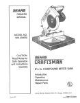
1 0
iNCH BENCH TOP
TABLE SAW
I
YOUR
SAFETY
• assembly
• operating
° repair parts
READ ALL
INSTRUCTIONS
CAREFULLY
Sears, Roebuck
Part No, SP6048
and Co., Hoffman
Estates, IL 60179 U,S.A.
Printed
in U.S.A,
6/97
p*
FULL ONE YEAR WARRANTY
ON CRAFTSMAN
TABLE SAW
If within one year from the date of purchase, this Craftsman Table Saw fails due to a defect in material or workmanship, Sears will repair it, free of charge.
WARRANTY SERVICE IS AVAILABLE BY SIMPLY CONTACTING THE NEAREST SEARS SERVICE
CENTER/DEPARTMENT THROUGHOUT THE UNITED STATES.
This warranty applies only while this product is used in the United States.
This warranty gives you specific legal rights, and you may also have other rights which vary from
state to state.
Sears, Roebuck and Co., D/B17 WA Hoffman Estates, IL 60179
3afoty
Instructions
For Table Saw
Safety Signal Words
When installing
DANGER: means if the safety information is not followed
someone will be seriously injured or killed
WARNING: means if the safety information is not followed
someone could be seriously injured or killed.
Avoid dangerous environment.
Before Using The Saw
WARNING: to avoid mistakes that could cause serf- I
ous, permanent injury, donor plug the table saw in _1
until the following steps have been satisfactorily I
completed.
I
To avoid injury from unexpected saw movement.
• Bolt or clamp the saw to firm level surface where there
is plenty of morn to handle and properly support the
workpiece (See page 18-19).
• Support the saw so the table is level and the saw does
not rock.
• When using a table extension on any side of the saw,
prop up the outer end of the extension from the floor or
bench top to keep the saw from tipping.
- Completely assemble and align saw (See pages 8-18)
• Put the saw where neither, operators nor bystanders
must stand in line with the sawblade.
• Learn the use and function of the ON-OFF switch (See
page 13) blade guard, spreader, anti-kickbackdevice,
miter gauge, rip fence, table insert, blade elevation and
blade tilt contro is (See page 21).
• Review the maintenance
page 34-35).
The Saw
• Use the saw in a dry, indoor place protected from rain.
Keep work area well lighted.
CAUTION: means if the safety information is not followed
someone may be injured.
• Review and understand all safely
operating procedures in this manual
Or Moving
• To avoid injury from electrical shock, make sure your
fingers de not touch the plug's metal prongs when
plugging in or unplugging the saw.
instructions and
• Never stand on tool. Serious injury could occur if the
tool tips or you accidentally hit the cutting tool. Do not
store any items above or near the tool where anyone
might stand on the tool to reach them.
methods for this saw (See
• Find and read all the warning labels found on the saw
(shown below)
When
servicing
use only identical
DOUBLE
INSULATED
replacement parts.
u o_ mm
•
u) L) _;(9
•
m_
•
[' R_ld m_rluot before u_ng _sw.
2
3.
W,_=_ •_l_zy
goggl_
Do rmt @_ _re_hl=r_d
tl
_.
Keep
_l
5, Ke_p hand_ _t
Id_a
guard
that me, el AN_I
€ u_$.
down
o_ pi|b
lad
6. W_n
Z87.1Stond_rdt.
In pile•
zsfs_w blade.
7.
_=_r through
I
u.m
•
li....
t
t--0)
_:uts.
ripping, ule pullh _ft=:k when fence h= eel 2/ncbol
mo_'e |tom blade.
Whin
ripping,
=Jim p_llh
_$ t_|
foefwee_
1/21114
block
2 _ncilel_
and _xllll_
|rom
IMIoe
bl_,de.
DOno_ make rip _uf$ rmrz_wer thlm 1/2 WCI'_.
whln
or
Ilsnce
& Know bow t_ reduc:e _e _l_k of k.Jckb_k.
Before
Each Use
inspect your saw.
=To avoid injury from accidental starting, turn the switch
off unplug the saw. and remove the switch key before
raising or removing the guard, changing the cutting
tool, changing the setup, or adjusting anything.
• Check for alignment of moving parts, binding of moving parts, breakage of parts, saw stability, and any
other conditions that may affect the way the saw
works.
• If any part is missing, bent or broken in any way, or any
electrical part does not work properly, turn the saw off
and unplug the saw.
• Replace damaged or missing parts before using the
saw again.
° Use the sawblade guard, spreader and anti-kickback
pawls for any thru-sawing (whenever the blade comes
through the top of the workpiece). Make sure the antikickback pawls work properly. Make sure the spreader
is in line with sawblade (See page 10-11).
o Make sure all clamps and locks are tight and no parts
have any excessive play.
• Remove adjusting keys and wrenches. Form a habit of
checking for and removing keys and adjusting
wrenches from table top before turning it on.
To Avoid injury From Jams, Slips Or Thrown
Pieces (Kickbacks Or Throwbacks)
-To avoid bums or other fire damage, never use the
saw near flammable licluids, vapors or gases.
-To avoid injury, don't do layout, assembly, or setup
work on the table while blade Is spinning. It could cut
or throw anything hitting the blade.
Plan your work
o Plan ahead to protect your eyes, hands, face. ears.
Use The Right Tool. Don't force tool or attachment to
do a job it was not designed for.
Dress for safety
° Do not wear loose clothing, gloves neckties or jewelry
(rings, wrist watches). They can get caught and draw
you into moving parts.
• Wear nonslip footwear.
• Tie back long hair.
• Roll long sleeves above the elbow.
• Noise levels vary widely. To avoid possible hearing
damage, wear ear plugs or muffs when using table
saw for hours at a time
° Any power saw can throw foreign objects into the
eyes. This car result in permanent eye damage. Wear
safety goggles (not glasses) that comply with ANSI
Z87.1 (shown on package). Everyday eyeglasses have
only impact resistant lenses. They are not safety
glasses. Safety goggles are available at Sears retail
stores. Glasses or goggles not in compliance with
ANSI Z87.1 could seriously hurt you when they break.
WEAR
YOUR
Inspect your blade.
• Choose the right blade or cutting accessory for the
material and the type ot cutting you plan to do,
• Never use grinding wheels, abrasive cutoff wheels.
friction wheels (metal cutting blades) wire wheels or
buffing wheels. They can fly apart explosively.
° Choose and inspect your cutting tool carefully:
-To avoid cutting tool failure and thrown shrapnel
(broken pieces of blade), use only 10 inch or smaller
blades or other cutting tools marked for speeds of
5000 rpm or higher.
- Always use unbroken, balanced blades designed to
fit this saw's 5/8 inch arbor.
-When thru-sawing (making cuts where the blade
comes through the workpiece top), always use a 10
inch diameter blade. This keeps the spreader in ctosest to the blade.
- Do not over tighten arbor nut. Use arbor wrenches to
"snug" it securely.
- Use only sharp blades with propedy set teeth. Consult a professional blade sharpener when in doubt.
- Keep blades clean of gum and resin.
• Never use the saw without the proper blade insert.
Inspect your work area.
• Keep work area clean.
• Cluttered areas and benches invite accidents.
must not be slippery from wax or sawdust.
= For dusty operations,
safety goggles.
wear a dust mask along with
Inspect your workpiece.
• Make sure there are no nails or foreign objects in the
part ol the workpiece to be cut.
° When cutting irregularly shaped workpleces, plan your
work so it will not slip and pinch the blade:
° A piece of molding for example, must lie flat or be held
by a fixture or jig that wil! not let it twist, rock or slip
while being cut. Use jigs or fixtures where needed to
prevent workpiece shifting.
• Use a different, better suited type of tool for work that
can't be made stable.
Plan your cut,
• To avoid kickbacks and throwbacks - when a part or atl
of the workpiece binds on the blade and is thrown wolently back toward the front of the saw:
- Never cut freehand. Always use either a rip fence.
miter gauge or fixture to position and guide the work.
so it won't twist or bind on the blade and kickback.
- Make sure there's no debris between the workpiece
Floor
and its supports.
Safety Instructions for Table Saw (continued)
-Use extra caution with large, very small or awkward
workpieces:
• Use extra supports (tables, saw horses, blocks, etc.)
for any workpieces large enough to tip when not held
down to the table top. Never use another person as a
substitute for a table extension, or as additional support for a workplace that is longer or wider than the
basic saw table, or to help feed, support or pull lhe
workplace.
• Never confine the piece being cut off. that is, the piece
not against the fence, miter gauge or fixture. Never
hold it, clamp it, touch it, or use length stops against it,
It must be free to move. Jf confined, it could get
wedged against the blade and cause a kickback or
throwback.
• Make sure the top of the arbor or cutting too! turns
toward the front of the saw.
Keep children away.
• Keep all visitors a safe distance from the table saw.
+ Make sure bystanders are clear of the table saw and
workplace.
Don't force tool.
* Letthe blade reach full speed before cutting.
o It will do the job better and safer at its designed rate.
- Feed the workpiece intothe saw only fast enough to let
the blade cut without bogging clown or binding.
Before freeing jammed material.
- Turn switch "OFF".
- Unplug the saw.
• Never cut more than one workpiece at a time.
- Wait for all mov=ngparts to stop.
o Check blade, spreader and fence for proper alignment
before starting again.
To avoid throwback of cut off pieces.
° Use the guard assembly.
• Never turn your table saw "ON" before clearing everything except the workplace and related support
devices off the table.
Plan the way you will push the workpiece through.
• Never pull the workplace through. Start and finish
the cut from the front of the table saw.
To remove loose pieces beneath or trapped inside
the guard,
- Turn saw "OFF"
• Never put your fingers or hands in the path of the
sawblade or other cutting tool.
• Never reach in back of the cutting tool with either
hand to hold down, support the workpiece, remove
wood scraps, or for any other reason.
° Avoid hand positions where a sudden slip could cause
fingers or hand to move into a sawblada or other cutting tool.
• Oon't Overreach. Always keep good tooting and balance.
- Remove switch key.
= Wait for blade to stop before lifting the guard.
Before leaving the saw.
• Turn the saw off.
o Wait for blade to stop spinning.
- Unplug the saw.
o Make workshop chUd-proof. Lock the shop. Disconnect
master switches. Remove the yellow switch key, Store
it away from children and others not qualified to use
the tool
• Push the workplace against the rotation of the blade.
Never feed material into the cutting tool from the rear
ot the saw.
Additional
• Always push the workplace all the way past the sawblade.
Before starting.
o Never use the miter gauge when ripping.
• Set the cutting tool as low as possible for the cut you're
planning.
Avoid accidental starting,
- Make sure switch is "OFF" before plugging saw into a
power outlet.
Sawblade
Is Spinning
WARNING: Don't allow familiarity (gained from frequent use of your table saw) cause a careless mistake. Always remember that a careless fraction of a
second is enough to cause a severe injury.
for
Rip Type Cuts
• As much as possible, keep your face and body to one
side of the sawblade, out of line with a possible kickback or throwback.
Whenever
Safety Instructions
-Use a push stick whenever the fence is
inches from the blade,
* When thru-sawing, use an auxiliary fence
block whenever the fence must be between
inches of the blade.
• Never thru-saw rip cuts narrower than 1/2
"Basic Saw Operations-Ripping
section.)
!
• Before actually cutting with the saw, watch it while it
runs for a short while. If it makes an unfamiliar noise or
vibrates a lot, stop immediately. Turn the saw off.
Unplug the saw. Do not restart until finding and correcting the problem.
2 or more
and push
1/2 and 2
inch. (See
and Bevel Ripping"
• Never rip anything shorter than 10" long.
• When using a push stick or push block, the trailing end
ot the board must be square. A push stick or block
against an uneven end could slip off or push the work
away from the fence.
• A Featherboard can help guide the workpiece. (See
"Basic Saw Operation-Using Featherboards for ThruSawing" section.)
• Alwaysuse featherboards
for any nonthru rip type
cuts.
Make From 3/4" Thick Solid Wood
E_
24"
When thru-sawing.
o To avoid kickbacks and slips into the blade, always
push forward on the section of the workpiece between
the sawbtade and the rip fence, Never push forward on
the piece being cut off.
Additional
Ko...
Abou,
4-1/2
_
!l
5 -"-I
Featherboard
• To avoid kickbacks and slips into the blade make sure
the rip fence is parallel to the sawblade.
o Before fhru-sawing, check the anti-kickback pawls.
(See "Basic Saw Operation - Using The Rip Fence."
The pawls must stop a kickback once it has started.
Replace or sharpen anti-kickback pawls when points
become dul!,
• Plastic and composition (like hardboard) materials may
be cut on your saw. However. since these are usually
quite hard and slippery, the anti-kickback pawls may
not stop a kickback. Therefore, be especially careful in
your setup and cutting procedures.
Crosscut
Safety
Instructions
For
Type Cuts
Before starting.
• Never use the rip fence when crosscutting.
o An auxilia_, wood facing attached to the miter gauge can
help prevent workpiece twisting and throwbacks. Attach it
to the holes provided. Make the facing long enough and
big enough to support your work. Make sure. however, it
will not interfere with the sawblade guard_
- Use jigs or fixtures to hetp hold any piece too small to
extend across the full length of the miter gauge face
during the cut. This lets you properly hold the miter
gauge and workpiece and helps keep your hands
away from the blade,
When cutting.
-To avoid blade contact, always hold the miler gauge as
shown in "Basic Saw Operations - Using The Miler Gauge
Glossary of Terms for Woodworking
Anti-Kickback Pawls (AKP)
Device which, when properly maintained, is designed to
stop the workpiece from being kicked back at the operator during ripping operation.
Arbor
The shaft on which a cutting tool is mounted.
Bevel Cut
An angle cutting operation made through the face of the
workpiece.
Compound Cut
A simultaneous bevel and miter crosscutting operation.
Crosscut
A cutting operation made across the width of the workpiece.
Dado
A non thru cut which produces a square sided notch or
trough in the workpiece.
Featherboard
A device which can help guide workpieces during rip type
operation.
Freehand
Performing a cut without the use of fence (guide), miter
gauge, fixture, hold down or other proper device to prevent the workpiece from twisting during the cutting operation. Twisting of the workpiece can cause it to be thrown.
Gum
A sticky, sap based residue from wood products.
Heel
Misalignment of the sawblade such that the blade is not
parallel to the miter gauge groove.
Kerr
The amount of material removed by the blade in a
through cut. Also the slot produced by the blade in a nonthrough or padial cut
Kickback
An uncontrolled grabbing and throwing of the workp_ece
back toward the front of the saw,
Leading End
The end of the workpiece which, during a rip type operation. is pushed into the cutting tool first.
Miter Cut
An angle cutting operation made across the width of the
workpiece.
Molding
A non through cut which produces a special shape in the
workpiece used for joining or decoration.
Push Stick
A device used to feed the workpiece through the saw
during narrow ripping type operations. The push stick
helps keep the operator's hands well away from the
blade.
Push Block
A device used for npping type operations too narrow to
a!low use of a push stick
Rabbet
A notch in the edge of a workpiece.
Resin
A sticky, sap based substance that has hardened.
Revolutions Per Minute (RPM)
The number of turns completed by a spinning object in
one minute.
Glossary of Terms for Woodworking (continued)
Rip Cut
A cutting operation along the lenglh of the workpiece.
Sawblade Path
The area oi the workpiece or table top directly in line with
either the tmvetof the blade or the part of the workpiece
which will be, or has been cut by the blade.
Set
The distance that the tip of the sawblade tooth is bent (or
set) outward from the face of the blade.
Throw-Back
Thru-Sawing
Any cutting operation where the blade extends
pletely through lhe thickness of the workpiece.
com-
Trailing End
The workpiece end last cut by the blade in a rippingoperation.
Workpiece
The item on which the cutting operation is being perlormed. The surfaces of a workpiece are commonly
referred to as faces, ends, and edges.
Throwing of pieces in a manner similar to a kickback.
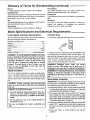
Motor Specifications
and Electrical Requirements
Power Supply and Motor Specifications
Polarized
The AC motor used in this saw is a universal, nonrevers-
Your unit has a plug that looks like the one shown below.
Plug
ible type having the following specifications:
Maximum Developed HP ........................................ 2-1/2
Voltage ......................................................................
120
Amperes ......................................................................
13
Hedz (Cycles) ............................................................
60
Phase ...................................................................
Single
RPM .........................................................................
4700
Rotation of Shaft ................................
Counterclockwise
WARNING: To avoid electrical hazards, fire hazards, or damage to the tool, use proper circuit protection. Yoursaw is wired at the factory for 120v
operation. Connect to a 120v, 15-amp branch cir-
worn
or cut, or damaged
in any way,
have it
• replaced immediately.
To reduce the risk of electrical shock, this appliance has
a polarized plug (one blade is wider than the other). This
plug will fit in a polarized outlet only one way. If the plug
does not fit fully in the outlet, reverse plug. If it still does
not fit, contact a qualified electrician to install the proper
outlet. Do not change the plug in any way.
WARNING:
Damaged power cords can cause
shock or fires. If the power cord is worn, cut, or
damaged in any way, have it replaced immediately.
tion.
WARNING: Double insulation
does not take the l
place of normal safety precautions when operating
this tool.
'
DANGER: To avoid electrocution:
1. Use only identical replacement parts when servicing a tool with double insulation. Servicing
should be performed by a qualified service technician.
2. Do not expose to rain, use in damp location or
where floor is wet.
This tool is intended
only.
for indoor
residential
use
'
IMPORTANT. To avoid
motor damag e , this motor should
be blown out or vacuumed frequently to keep sawdust
from interfering with normal motor ventilation,
1, Connect this tool to a 120v, 15-amp branch circuit With
a 15-amp time delay fuse or circuit breaker. Using the
"
"
2.1f the motor won ' t st a rt,_tumth es wit"c h "OFF " immediately. Unplug The Tool. Check the sawblade to make
sure it turns freely. If the blade is free. try to start the
motor again. If the motor still does not starl, refer to the
"Troubleshooting Chart" on page 35.
3. If the motor suddenly stalls while cutting wood, turn the
switch "OFF", unplug the tool, and tree the blade from
the wood. The motor may now be restarted and the cut
finished.
4. Fuses may "blow" or circuit breakers
quently if:
may trip fre-
a.MotorIs Overloaded.
Overloading
canoccurif you 5.Most motor troubles may be traced to Boose or #_c:orfeedtoo rapidlyor maketoo manystart!stopsin a
rect connections, overload, low voltage (such as sm_ll
shorttime.
size wire in the supply circuit) or h_ overly tong s,JpP{Y
b.Voltagesnot morethan 10%aboveor belowthe
circuit wire. Always check the connections, the load
nameplatevoltagecan handlenormalloads.For
and the supply circuit whenever motor doesn't work
heavyloads,however,the voltageat motortermiwell. Check wire sizes and length with the Wire S_ze
Chart.
nalsmustequalthevoltagespecifiedonnameplate.
Overload
Protection
Your saw features a reset overload relay button. If the
motor stops running or fails to start (due to feed pressure too fast, dull blade or low voltage), turn switch
"OFF", let the motor cool three to five minutes and
push the reset button, which resets the overload
device and allows you to turn the saw back on.
Wire Size
NOTE: Make sure the proper extension
is in good condition.
The
use of any extension
cord wi!l cause
some
toss
of
power, To keep this to a rninimum and to prevent over
heating and motor burnout, use the table to determine
the minimum wire size (A.W,G.) extension cord.
WARNING: The ON/OFF switch should be in the off
position, and the plug removed from the power
source while the cool down takes place to prevent
accidental
starting when the reset button is
pushed, Overheating may be caused by misaligned
parts or dull blade, Inspect your saw for proper
setup before using it again,
cord is used _d
Extension Cord
Length
Wire Sizes Required
(A.W.G,)
t10-120V
0-25
14
26-50
12
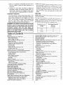
Table of Contents
Warranty .........................................................................
2
Safety Instructions For Table Saw ...............................
2
Safety Signal Words: ................................................... 2
Before Using The Saw: ............................................... 2
When Installing Or Moving The Saw: ......................... 2
Before Each Use: .......................................................
3
Whenever Sawblade Is Spinning: ............................... 4
Additional Safety Instructions for: ................................ 4
Rip Type Cuts ..............................................................
4
Before starting .............................................................
4
Additional Safety Instructions For: ........................... _..5
Crosscut Type Cuts .....................................................
5
Glossary of Terms for Woodworking .............................. 5
Motor Specifications and Elec{rical Requirements ........ 6
Power Supply and Motor Specifications ...................... 6
Double Insulation ........................................................
6
Polarized Plug .............................................................
6
Motor Safety Protection ............................................... 6
Overload Protection ..................................................... 7
Wire Size .....................................................................
7
Table of Contents ...........................................................
7
Unpacking and Checking Contents ................................ 8
Tools Needed ..............................................................
8
Table of Loose Parts ................................................... 8
List of Loose Parts in the Box and Bags ..................... 9
Assembling Handle to Handwheel ................................. 9
Blade Guard Assembly ................................................ 10
Blade Guard Alignment ................................................ 11
Checking Anti-kickback Pawls .................................... 11
Rip Fence Assembly and Adjustment .......................... 12
Rip Fence Alignment ....................................................
12
Rip Fence Indicator Adjustment ................................... 13
Miter Gauge and indicator Adjustment ........................ 13
On-Off Switch ...............................................................
13
Blade Tilting Control and Lock Lever Adjustment ........ 14
Adjusting 90 and 45 Degree Positive Stops ................. 14
Adjusting Positive Stop at 90 Degrees ...................... 14
Adjusting Positive Stop at 45 Degrees ...................... 14
Blade Tilt Indicator Adjustment .................................... 15
Checking Blade Parallel to the Miter Gauge Groove ..
Adjusting Blade Parallel to Miter Gauge Groove .........
Removing Sawblade ....................................................
Installing Sawblade ......................................................
Mounting Table Saw to Workbench, Cabinet or Legsei
Workbench Mounting Using Hardware .....................
Workbench Mounting Using "C" Clamps ...................
Cabinet or Legset Mounting Using Hardware ...........
Assembly ...................................................................
Getting to Know Your Table Saw ................................
Work Feed Devices ......................................................
Push Stick .................................................................
Push Block ...............................................................
Auxiliary Fence .........................................................
Safety Instructions for Basic Saw Operations ..............
Before Each Use: ......................................................
Whenever Sawblade Is Spinning: .............................
Basic Saw Operations ..................................................
Additional Safety Instructions for Crosscutting ..........
Crosscutting ...
...........
Repetitive Crosscutting .............................................
Miter Crosscutting
..................................... ..............
Bevel Crosscutting ..................................................
Compound Miter Crosscutting ...................................
Additional Safety Instructions for Rip Cuts ...............
Ripping ..
...............................................
Bevel Ripping ...........................................................
Resawing ...................................................................
Dadoing .......................................................................
Rabbeting ..................................................................
Ploughing or Molding .................................................
Installation and Operation of Molding Head .................
Maintaining Your Table Saw .....................................
Maintenance ..............................................................
Lubrication ............................................
Sears Recommends the Fol ow ng Accessor es .........
.........................................
15
16
17
t7
18
18
18
18
19
20
22
22
22
23
24
24
25;
26
26
26
27
27
27
28
28
29
30
31
33
33
34
34
34
35
35
3_
Troubleshooting
...............
37
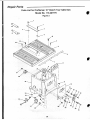
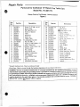
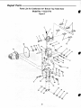
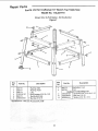
Repair Parts ........................................
43
Notes ......................................................................
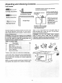
Unpacking and Checking Contents
Tools Needed
Combination
accuracy
Square
as shown
must
#2 Phillips Screwdriver
Combination
Draw light line on board
alon edge
Square
be true. Check
its
below.
Medium Screwdriver
Select the straight edge of
3/4" thick board. This edge
must be perfectly straight,
/
NOTE: The square and
straight edge are used
to align the saw.
They must be accurate
if the saw is to be
aligned properly,
Adjustable Wrench
Should be
gap or overlap
here when square is flipped
over in dotted position
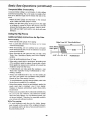
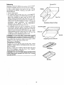
Apply a coal of automobile wax to the table. Wipe al
parts thoroughly with a clean, dry cloth. This will reduce
friction when pushing workpiece.
Separate all parts lrom packing material and check each
one with the illustration and the list of Loose Parts to
make certain all items are accounted for, before discarding any packing material.
wARNING: If any parts are missing, do not attempt I
to assemble the table saw, plug in the power cord
or turn the switch on until the missing parts are
obtained and are installed correctly.
!
WARNING: For your own safety, never connect
plug to power source outlet until all assembly
steps are complete, and you have read and understand the safety and operating instructions.
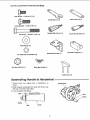
Table of Loose Parts
Item
A
B
C
D
E
F
Description
Qty
Table Saw Assembly .......................................
Miter Gauge .....................................................
Blade Guard and Spreader ..............................
Rip Fence (Without Handle) ............................
Owner's Manual ...............................................
Bag ol Loose Parts .........................................
1
1
1
1
1
*
bag together and separate from contents of other bags.
B
List of Loose Parts in the Box and Bags
Hex Screw - 1/4-20 x 1/2" (2)
Arbor Wrench (1)
Shaft Wrench (1)
Carriage Bolt - 1/4-20 x 718" (1)
Handle (Rip Fence) (1)
Hex Screw - 1/4-20 x 2-1/8" (1)
Knob (Handwheel)
Flat Washer (1)
©
Spreader
1/4" External Lockwasher 14)
Bracket
Spreader Support
(1)
Q
Nut Hex 5116-18 (1)
Wing Nut 114-20 (1)
Switch
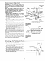
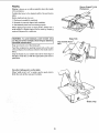
Assembling
1. Thread screw
shown.
Handle to Handwheel
into tapped hole in handwheel,
as
2. When properly assembled, the knob will rotate freely
with only a small amount of play.
3. Lock nut against handwheel.
1/3_
Screw
\
Nut
\
Knob
Handwheel
Key (1)
(1)
(1)
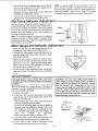
Blade Guard Assembly
1. From among the loose parts, locate the following hardware:
0
Hex Screw 1/4-20 x 1t2" (2)
114"External
Lockwas her (4)
Hex Screw - 114-20 x 2-1/8" (1)
Carriage Bolt - 1/4-20 x 7/8" (1)
0
Flat Washer (1)
Wing Nut 1/4-20 (1)
Spreader Support I1)
Spreader Bracket (1)
2. Position large recessed shoulder end of the
spreader support against end of pivot rod and fasten
to table using the 1/4-20x2-1/8" long hex screw and
1/4" external tooth Iockwasher.
/
_ _asher
_X
1/4"
Screw ,,
1/4-20 x 2-1/8
..
Spreader
Support
3. Position the spreader bracket to the spreader support as shown. The 1/4-20xl/2" screws and lockwashers are to be assembled finger tight only at this
time.
Bracket
4. Insert the 1/4-20 x 7/8" carriage bolt in the square
feature o1 the spreader bracket as shown. Assemble
the flat washer first, then the 1/4 external Iockwasher
and the 1/4-20 wing nut on the carriage holt leaving
the wing nut loose at this time.
Spreader
5. Assemble blade guard and spreader by positioning
the open slot in the spreader directly above the
shouldered part of the rivet attached to the spreader
bracket. Slide the spreader down between the
spreader bracket and the head of the rivet until either
Blade Guard
and Spreader
Shouldered
the open slot sets on the rivet or the spreader sets
on the table top surface. Tighten wing nut.
Win
NOTE: Both washers must be positioned between the
spreader and the wing nut.
Lockwasher
10
114
Carriage Bolt
1/2-20x7/8
Blade Guard Alignment
IMPORTANT: To work properly, the spreader must
always be adjusted so the cut workpiece will pass on
either side of the spreader without binding or skewing to
the side.
Blade Guard
t
NOTE: The spreader is thinner than the width of the
KERF by approximately six thicknesses of newspaper.
BladE
/
Arm
NewspaperL__Spreader
To check if alignment is proper, slide 3 thicknesses of
newspaper between straight edge and spreader.
Readjust if necessary.
1. Make two folds in a small piece (6" x 6") of ordinary
newspaper making three thicknesses. The folded
paper will be used as a "spacing gauge".
2. Raise blade to maximum height and make sure blade
is in vertical position (straight up and down) or at "0_"
blade angle.
Straigh_---'c_-_-.-_J'_-_!
3. Lay a piece of straight flat wood or straight edge
against the sawblade. Insert folded paper between
spreader and wood strip.
4. Make sure the three hex screws are loose enough to
slide spreader bracket and to rotate spreader support.
Position flatwasher & !ockwasher
on this side of spreader
Space equals 3
thicknesses of
5. Lift the anti-kickback pawl to clear the wood or straight
edge and hold the spreader tightly against the paper
and wood. Make sure the wood is against the sawblade. Tighten the three hex screws.
This will align the spreader in the middle of the cut
(KERF) made by sawblade.
NOTE: To remove the guard for non-through cuts, loosen
the wing nut and slide the guard upward off the soreader
bracket. Do not disturb the setting of the spreader support bracket.
paper _
Anti-kickback
Wood
\
J
Blade
/
When replacing the guard, slide the spreader down onto
the spreader support bracket with the washers directly
under the wing nut. Make sure the wing nut is tightened
securely. This lets you remove and replace the guard
without disturbing the spreader alignment.
Checking
'J"_.._Snreader
/
/
/
Looking Down on Saw
/
Space equals 3
thicknesses of
paper
Pawls
1. Raise blade guard up to upright position.
2. Rotate both pawls up toward rear el spreader. Let
pawls go to make sure they return freely by spring
force to their normal position.
Anti-Kickback
3. Slide a sample workpiece under a pawl and pull it
toward the front of the saw. Repeat for both pawls.
4. The anti-kickback pawl should prevent the workpiece
from moving toward the front of the saw.
/
,laise
Pawls
5. See page 33 for instructions on how to sharpen the
teeth of the anti-kickback pawls.
t°' i
11
Rip Fence Assembly and Adjustment
Q
WARNING: To prevent personal injury, always dis- I
connect plug from power source when making
adjustments.
L
t_ Thread 5/16-18 nut all the way onto the fence locking
handle.
2. Thread rip fence locking handle into cam until tight.
Lock the nut against cam with wrench.
Nut Hex 5/16-18 (1)
Handle (Rip Fence) (1)
3. Place the rip fence on the table and lower the rip fence
locking handle until the rip fence is secure to front rail.
4. Check to see if rear clamp on the dp fence is loose, If
not, turn the rip fence adjustment screw counterclockwise until the rear clamp on the rip fen ce is loose with
the fence assembly locked to the front rail.
5. With fence assembly locked to front rail, turn the rip
fence adjustment screw clockwise until rear clamp is
snug.
6_ Raise the rip fence locking handle.
7. Turn the rip fence adjustment screw clockwise an additional 1/2 turn.
Rear Clamp
8. Check the rip fence by applying moderate side pressure to the rear of the fence assembly. If the rip fence
deflects easily raise the rip fence locking handle and
turn the rip fence adjustment screw clockwise another
1/4 turn.
O
9. Check rip fence again by applying moderate side pressure to the rear of the fence assembly. If necessary
repeat step 8 until rip fence is secure.
NOTE: Overtightening the rip fence adjustment screw
may cause the rip fence to be loose on the front table rail.
Rip Fence Alignment
' WARNING: To prevent personal injury, always disconnect plug from power source when making
adjustments.
Miter Gauge
the blade to minimize the danger of kickback. For
convenience, the rip fence will be aligned parallel
to the miterThe
gauge
slot. The
willparallel
be set or
I CAUTION:
rip fence
mustsawblade
be aligned
to
adjusted parallel to the slot later.
....
1. Place the ri_
cent to the miter gauge groove.
2. Lower the rip fence locking handle to secure the rip
fence.
3. Check to see that the edge of the ri_
with the miter gauge groove
If the rip fence is not parallel:
o Raise the rip fence locking handle.
° Loosen the two hex head screws located on top of
the rip fence.
• Align the rip fence parallel to the miter gauge groove,
=Lower the rip fence locking handle.
-Tighten the two hex head screws previously loosened.
12
Rip Fence
Adjusting Screws
• Raise the rip fence rocking handle, move and return
the rip fence adjacent to the miter gauge groove,
lower the rip fence locking handle,
NOTE: To always obtain the best alignment of the rip
fence, develop the habit ol holding the front casting on
the lence back against the table top while tightening the
• Repeat and recheck steps 8 and 9 in the "Rip Fence
Assembly and Adjustment" section,
fence lock handle. Tighten the rip |ence tock handle
securely to prevent rip fence movement while sawing.
• The rip fence should now be parallel to the miter
gauge groove, It not. repeat steps and recheck.
Rip Fence Indicator
Adjustment
........
With the rip fence locked to the table measure the distance from the side of the rip fence to the nearest side of
the blade. The indicator should point to the same marking
on the scale. If it does not, loosen the screw holding the
indicator, move the indicator to the correct marking on
the scale and tighten the screw.
HINT: The rip fence indicator will need to be readjusted
whenever a thicker or thinner blade is installed. When
Scai____1_
making critical cuts, make a trial cut on scrap wood rather
than relying on the rip scales.
Screw/
Miter Gauge and Indicator Adjustment
1. Check to make sure the miter gauge will slide freely
through both entire table grooves before using it,
2. To adjust the miter gauge, loosen lock knob and set
the miter gauge body so the scale is at the 90' mark,
then tighten lock knob,
3. Make a cut on a piece of scrap wood. Check it with a
square to see if the piece ol wood was cut at 90 °. If the
piece was not cut 90° . adjust the miter gauge body,
tighten lock knob and make additional cuts until you
are ceratin you have made a 90 ° cut.
4. Loosen the miter scale adjustment screw set the indicator point on the 90° mark on the scale and tighten
screw,
On-Off Switch
I
the blade guard is correctly installed and operating
I CAUTION:
Before turning switch "ON", make sure I
properly.
The On-Off switch has a locking feature. This feature is
intended to prevent unauthorized and possible hazardous use by children and others.
1_ insert key into switch.
2. To turn saw "ON", stand to either side of the blade.
never in line with it: insert finger under switch lever
and pull end of lever out.
- After turning switch "ON". always allow the blade to
come up to full speed before cutting.
-Do not cycle the motor switch on and off rapidly as
this may cause the sawblade to loosen. In the event
this should ever occur, allow the sawblade to come
to a complete stop, unplug saw and retighten the
arbor
nut
normally,
not
excessively.
- Never leave the saw while the power is "ON".
WARNING: For your own safety, lower blade or
other cutting tool below table surface. (If blade is
tilted, return it to vertical, 90 ° position). Always
lock the switch "OFF". When saw is not in use,
remove key and keep it in a safe place. Also, in the
event of a power failure (all of your lights go out)
turn switch off and lock it by removing the key.
This will prevent the saw from starting up again
when the power comes back on.
Switch Key
3. To turn saw "OFF", push lever in. Never leave the saw
until the cutting tool has come to a complete stop.
4. To lock switch in "OFF" position, hold switch in with
one hand and remove key with the other hand.
13
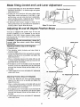
Blade Tilting Control and Lock Lever Adjustment
1. Loosen blade tilting lock lever and slide the elevation
handwheel until blade is at desired angle and tighten
blade tilt lock lever.
EJevation Handwheel
2. If blade lock lever interferes with some object before
blade tilting control mechanism is held tight or rigid,
pull lock lever out and rotate lock Fever counterclockwise to another position. Tighten lock lever. Recheck
for proper adjustment of blade tilt lock lever,
3. I1 lock lever won1 loosen enough so blade can be
tilted, pull lock lever out and rotate lever clockwise to
another position. Tighten blade lock lever,
Blade Tilt Lock Lever
Adjusting 90 and 45 Degree Positive Stops
Your saw is equipped with positive stops for last and
accurate positioning ol the sawblade at 90 and 45
degrees to the table. Always measure blade position
from the left side of the blade. Blade insert may not be
flush with table top.
prevent personal injury, ahvays dis- I
connect plug
power
I WARNING:
source _vhen making I
adjustments.To from
Blade insert
!
Adjusting
Positive Stop at 90 Degrees
1. Unplug the saw.
2. Turn elevation wheel clockwise
and raise blade to
maximum height,
3. Loosen the blade tilt lock lever and push the elevation
wheel to the left as far as possible and tighten the
blade tilt lock lever
4. Place a combination square on the table with one end
of square against the blade as shown and checkto see
if the blade is 90 ° to the table.
5. If the blade is not 90° to the table, loosen the blade tilt
lock lever, loosen 90 ° adjustment screw (A) a few turns
and push the elevation wheel until the blade is 90 ° to
the table
\
6. Tighten blade tilt lock lever and tighten 90 ° adjustment
screw until it stops.
"
t Screw (A)
90 ° Adiustmen
\
45 ° Adjustment
Adjusting
Positive
Screw (B)
/
Stop at 45 Degrees
1. Loosen the blade tilt lock lever and push elevation
wheel to the right as far as possible and tighten the
blade tilt lock lever.
/
2. Place a combination square on the table with one end
ol the square against the table as shown, and check to
see if the blade is 45 ° to the table,
3. It the blade is not 45 ° to the table loosen the blade tilt
lock lever, loosen 45 ° adjustment screw (B) a few turns
and push the elevation wheel until the blade is 45 ° to
the table.
4. Tighten blade tilt lock lever and tighten 45 ° adjustment
screw until it stops,
14
/
Blade Tilt Indicator
Adjustment
1. With 90 ° positive stop set and blade tilt control pushed
against this stop, loosen indicator screw, adjust indicator pointer to "0" degrees and retighten indicator
screw.
Indicator Pointer
NOTE: When making critical cuts. make a trial cut on
scrap wood rather than relying on the tilt scale or stops.
Indicator
Screw
Checking Blade Parallel to the Miter Gauge Groove
WARNING: To avoid injury from accidental start,
make sure switch is "OFF" and plug is not connected to power source outlet.
The blade was adjusted parallel to the miter gauge
groove at the factory, in order to insure accurate cuts and
help prevent kickback, this adjustment should be
rechecked, If adjustment is necessary follow the steps
below.
WARNING: If the sawblade is NOT parallel with the
miter gauge groove, it is said to have "HEEL". This
condition can cause the workpiece to bind or move
away from the rip fence at the end of a rip cut, possibly causing a kickback.
/
1, Unplug saw.
/
Mark "X" on tooth
2. Turn elevation whee, and raise blade as high as it will
go.
3. Lift blade guard if already installed, to its highest position.
4. Select a tooth on the front of sawblade that is set to the
right when viewing blade from the front of the saw. and
mark this tooth with a pencil
5. Place the base of a combination square against the left
edge of the right miter gauge groove, and extend the
sliding rule ol square so it just touches the marked
tooth.
6. Rotate blade and check the same marked blade tooth
at the rear of the saw table.
7. If the front and back measurements are not identicaL,
the mechanism must be adjusted to make the blade
PARALLEL to miter gauge groove,
15
Adjusting Blade Parallel to Miter Gauge Groove -WARNING: To avoid injury from accidental start,
make sure switch is "OFF" and plug is not connected to power source outlet.
Secondary
ALignment
Screws
I CAUTION: Fold a piece of cardboard over the blade
I to protect your hand
Alignment
Screws
(A)
NOTE: Always review the section "Checking Blade Parallel to the Miter Gauge Groove" before proceeding with
this section.
1. Should your saw require adjustment the alignment
screws must be loosened It you are unable to loosen
the alignment screws from the top using a #2 Phillips
screwdriver proceed as follows:
2. Unplug the saw.
3. Remove the table insert.
4. Remove the blade.
5. Turn saw upside down.
6. Locate the 4 nuts attached to the alignment screws
(A). Loosen these nuts 1/2 turn.
7. Turn saw right side up and install blade
8. Loosen 1/2 turn the four alignment screws (A) in the
top of table next to the sawblade. This will allow the
mechanism below the table to be shifted sideways.
9. Fold a piece of cardboard over the blade to protect
your hands.
10. Grasp the blade and the spreader support mechanism and move it to either the right or left a small
amount as needed to make the square Iouch the
same amount front and rear. Tighten one screw.
Cardboard
11. Check with square to determine if marked tooth
touches square by the same amount at front and
rear.
If it does, alternately tighten the other three screws
slowty.
If it does not, loosen screws and move blade the
required amount.
NOTE: If adjustment cannot be achieved by loosening
the four alignmen! screws (A), loosen the two secondary alignment screws (B) only if it is absolutely necessary to make this adjustment.
12. Recheck blade clearance to table and table insert to
make sure blade does not hit at both 90 and 45
degree blade tilt.
13. If you cannot complete the alignment using alignment
screws (A), then proceed to secondary alignment
screws (B), if you cannot loosen secondary alignment
screws (B), remove blade and turn saw upside down,
Locate the 2 nuts that are attached to the secondary
alignment screws IB) and loosen nuts 1/2 turn.
14. Turn saw upright, reinstall blade and repeat steps 1
thru 5.
15. Once saw blade has been aligned, the screws need
only to be tightened from the top side
16. Reinstall the table insert and blade guard. Continue
the assembly procedure as outlined in your owners
manual.
16
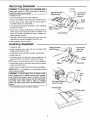
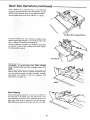
Removing Sawblade
Loosen
WARNING: To avoid injury from accidental start,
make sure switch is "OFF" and plug is not con-
Open End Arbor"_
nected to power source outlet.
1. Unplug the saw.
"_-"_'_
Shaft Wrench
-- \
_
Stop or=Table f'°
_"
Closed End
) j Arbor Nut
f/"...Wrench
_-_
2. Remove blade guard and retain hardware,
3. Remove the phillips head screws from the blade insert.
4. Lift the blade insert noting that the formed edge is
toward the blade. Set insert aside.
5. Turn elevation handwheel clockwise to raise sawblade
as high as it will go.
6. Insert
motor
arbor
hands
open end arbor shaft wrench over flal portions ol
spacer and closed end arbor nut wrench over
nut. Position wrenches as shown holding your
well above blade.
d_i/
J
/-'Arbor
Nut
7. Hold arbor wrench against table and loosen arbor nut
with arbor nut wrench by pulling it forward to you.
8. Slide sawblade off motor shaft.
Installing Sawblade
1. Unplug the saw.
2. Install sawblade onto shaft with the top blade teeth
pointing toward front of saw.
3_ Install blade collar with hollow surface toward blade.
Closed End
Arbor Nut
;k_
4. Install arbor nut.
ench
5. To tighten arbor nut, hold arbor wrench against rear of
table, push arbor nut wrench towards rear of table,
L
NOTE: Arbor nut should just be snug. Do not overtighten.
6. Install blade insert in the table recess with its formed
edge toward the blade.
Tighten
_r//
Blade
!
_'-Insert
Arbor Nut
7. Insert screws through front and rear holes and tighten.
IMPORTANT: Do not attempt to run saw without blade
collar properly installed.
Collar
WARNING: To avoid injury from a thrown workpiece, blade parts, or blade contact, never operate
saw without the proper insert in place. Use the
sawblade insert when sawing. Use the dado/molding head insert when using a dado or molding
head. See page 34 for Sears recommended accessories.
Top Teeth Pointing
to Front of Saw
8. Re-install blade guard and tighten wingnut.
Formed Edge
\
\
17
"_._'_
'_--_"_
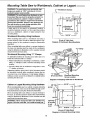
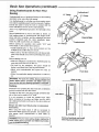
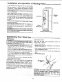
Mounting Table Saw to Workbench, Cabinet or Legset -WARNING: To avoid injury from accidental start,
make sure switch is "OFF" and plug is not connected to power source outlet.
--- Workbench Surface
................
m
......
i
I
WARNING: To avoid injury from kickback or saw
movement the saw must be properly secured to a
sturdy workbench, cabinet or legset. Casters if
provided onthe cabinet or legset must be locked
during saw operation. If there is any tendency for
the saw to move or rock during operation, this
must be corrected immediately.
;o ---T
I
Mounting
3/8" Dia!'
9/1_"
5 _
=,'Opening if
Vacuum
is not used
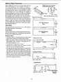
If table saw is to be used in a permanent location,
should be fastened securely to a firm supporting surface
such as a workbench, cabinet or tegset using the four
mounting' holes.
Workbench
I
!
_0_
I-_--
Using Hardware
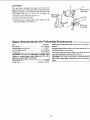
When mounting table saw to a workbench and using a
vacuum hookup, holes should be drilled through the supporting surface of the workbench using the dimensions
illustrated.
16_9116"--------_1
(Front of Table Saw)
Diagram of Workbench Mounting Holes
When mounting table saw without a vacuum hookup to
the base, an opening must be made in the workbench
using the dimensions illustrated, so the sawdust can fall
away from the Saw base area.
Workbench
Mounting
Using
%__.
"C" Clamps
_-_ _"C" Clamp
An alternative method of securing your table saw is to
fasten the saw base with "C" clamps.
1. Follow instructions for mounting to workbench, substituting "C" clamps in each recessed mounting screw
Iocalion.
2. Securely clamp saw to workbench using three or 10ur
"C" clamps, as shown.
Supporting surlace where saw is to be mounted should
be examined carefully after mounting to insure that no
rnovement can occur during use. If any tipping, sliding or
walking is noted, secure the workbench or cabinet before
operating the table saw.
"C" Clamps
(Front and Rear)
Recessed Mounting
Screw Location
Diagram of Clamping Table Saw to Workbench
Cabinet or Legset Mounting
Using Hardware
-3/8" Dia.
2-7/16"
When mounting table saw to a cabinet or legset and using
a vacuum hookup, holes should be drilled through a 3/4"
thick plywood base using the dimensions illustrated.
20"1/2"'--"---_
"-"
T
When mounting table saw without a vacuum hookup to
the base, an opening must be made in the plywood base
using the dimensions illustrated, so the sawdust can fall
away from the saw base area.
I
I"-
,
2-1/2"
T
.
16 1/8"
21"
Opening_
I legset.
WARNING:
Nevercould
clamp
theYou
table
sawbedirectly
to a II
The saw
fall.
could
badly cut.
if vacuum|
is not
|
used
O
l-._---
16-9116" _
(Front of Table Saw
Diagram of Cabinet Mounting
18
I-,=_--2"
Holes
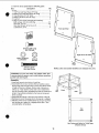
1. From the loose parts find the following pads.
Item
Description
Qty
A Leg .................................................................................
4
1 Top Front and Rear Brace (18" long) ............................ 2
2 Bottom Front and Rear Brace (22" long) ...................... 2
3 Top side brace (17-1/2" long) ........................................ 2
4 Bottom side brace (22-1/2" long) ................................... 2
5 Leg Pad .......................................................................
4
6 Bag of Loose Parts Containing the Following:
Bolt carriage, 5/t 6-18 x 5/8" long ..............................
24
Hex Nuts, 5/16-18 .................................................
28
Hex Head Screws. 5/16-18 x 2-1/2 ..............................
4
Lockwashers. 5/16 .....................................................
4
1
A
A
Front and Rear
3
5/16-18 x 5/8" Long
Bolt Carriage
© ©
5/16 In. External
Lockwasher
Right and Left Sides
5/16-18
Hex Nut
5/16-18 x 2-1/2"
Hex Head Screw
5
4
NOTE: Letter and number identifiers are stamped into parts.
WARNING: For your own safety, turn switch "OFF" and
remove plug from power source outlet before mounting
power tool onto leg set.
Assembly
1. Install one leg pad onto bottom of each leg.
2. Assemble front and rear sections first by inserting screws
through legs then through braces. Braces are always inside
of legs and top brace flanges. Shorter side of braces are
always up. Finger tighten screws and nuts as adjustment
may be necessary later. Assemble front and rear sections as
shown. Pay particular attention to the hole and screw patterns as shown ......
Front
Side
3. Assemble side braces to front and rear sections of leg set
4. Hardware to mount the power tool to the leg set is supplied.
5. After the power tool is mounted to the leg set you may then
shift the leg set to adjust for a slightly unlevel floor. Then
securely tighten all hardware.
W
Top
View
Use Outermost Holes for Table Saws
(Shaded Areas)
19
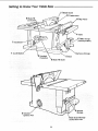
Getting to Know Your Table Saw
/1 1 Blade Guard
/
/
/12 Table insert
/
6 Blade Tilt
10 Rip Fence
_'4
7 Handwheel
Table
3 Miter Gauge
(stored position)
/
1 On-Off Switch
Rip Fence
_"_
Overload
Protection
Storage
5 Base
8 Blade Tilt Scale
I Wrench
Storage
Ejection Port
ge
on Non-thru Cuts
2O
1. On-Off Switch.
CAUTION: Before turning switch "ON", make sure
the blade guard is correctly installed and operating
properly.
.V=leOn-Off
intended to
ardous use
2. Overload
Switch has a locking feature. This feature is
help prevent unauthorized and possible hazby children and others.
Protection
Your saw features an overload relay reset button, If the
motor stops running or fails to start (due to feed pressure
too fast dull blade or low voltage), turn switch "OFF".
Unplug the saw. Let the motor cool three to five minutes
and push the reset button, which resets the overloaded
device and allows you to turn the saw back on.
position, and the plug removed from the power I'
whileThe
the on/off
cool down
place
I source
WARNING:
switchtakes
should
be toin prevent
the off II
accidental starting when the reset button is pushed.
3. Sawdust Ejection Port
Your table saw is equipped with a vacuum hookup. This
feature will allow you to attach any standard 2-1/2 inch
diameter wet/dry vacuum hose into the hole provided for
convenient sawdust removal,
ignite sawdust. Even if saw is connected to vacI WARNING: Sawdust can clog motor. Motor could
uum, blow out sawdust regularly.
_ Table
_ovides large working surface to support workpiece.
5. Base
Supports table. For additional stability, holes are provided in base to bolt the saw to a workbench or stand
6, Blade Tilt Lock Lever
Clamps the tilt mechanism alter the blade is adjusted to
desired position. Use handwheel as a lever to tilt blade.
7. Handwheel
Elevates or lowers the blade. Also used as a lever to tilt
the blade from 0 to 45 degrees.
8. Blade Tilt Scale
Shows the degree the blade is tilted,
9. Wrench Storage
Conveniently stores shaft and arbor nut wrenches,
10. Rip Fence
Exclusive self-aligning, quick-set rip fence can be easily
moved or locked in place by simply raising or lowering
lock handle. Holes are provided in the rip fence for
attaching
a
wood
facing.
WARNING: When positioning fence for maximum
rip, make sure end of fence head is even with the
edge of the table. Fence cannot be locked securely
beyond the edge of the table. The workpiece could
bind and kickback.
11. Blade Guard
Use the sawblade guard, spreader and anti-kickback
pawls for any thru-sawing (whenever the blade comes
through the top of the workpiece). Make sure the antikickback pawls work properly. Make sure the spreader is
in line with sawblade.(See page 10-11)
To remove the guard for special operation, loosen wrng
nut and slide the spreader up. Do not disturb the setting
of the spreader bracket.
Whe_ replacing the guard, slide spreader down over tile
spreader bracket. Hand tighten wing nut securely.
12. Table insert
Is removable for removing or installing blade or other cutting tools.
WARNING: For your own safety turn switch "OFF" I
and remove plug from power source before removing insert.
t
To remove the insert.
A. Lower the blade below the table surface.
B. Raise blade guard.
C. Remove insertscrews and lift insertfrom pocket in table
WARNING: To avoid injury from a thrown workpiece,
blade parts, or blade contact, never operate saw without the proper insert in place. Use the sawbiade
insert when sawing. Use the dado/molding head
insert when using a dado blade or moldin_l head.
13. Miter Gauge
Head can be locked in desired position for cross cutting
or mitering by tightening the lock knob. Always securely
lock it when in use
Notches are provided in the miter gauge for attaching an
auxiliary facing to make it easier to cut longer pieces. Be
sure facing does not interfere with the proper operation of
the sawblade guard.
Select a piece of smooth straight wood approximately 3/4
inch thick, at least as along as the rip fence, and at least
7-1/2" wide (high) to permit clamping of leatherboards.
_ttach
brews
it to the fence with two round head #10 wood
1-5/8" long.
Select a suitable piece of smooth straight wood. drill two
holes through it and attach it with screws.
NOTE: When bevel crosscutting, attach facing so that it
extends to the right of the miter gauge and use the miter
gauge in the groove to the right of the blade.
21
Work Feed Devices
Slightly Less Than Thickness
Belore cutting any wood on your saw, study all of the
"Basic Saw Operations" found on pages 23 through 33.
.,_3/4"
As you learn new table saw woodworking techniques,
you'll see that many types of cuts need different support
and feeding devices, known as jigs or lixtures. They can
help you make cuts more accurately. By helping to
steady the workpiece and keep you away from the blade,
they can helpyou safely use your saw for certain cuts.
Many people custom build their own jigs and fixtures.
Jigs and fixtures are often designed for a particular cut_
Of Workpiece Up To
NOTE: All dimensions in inches
Material for Push Block
You can use your table saw to easily make many jigs and
lixtures. To get you started we've included instructions
for some simple ones. After you have made a fe_- practice cuts. make up these jigs before starting any projects.
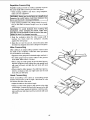
Make the push stick first.
_-_
At Least12"
_,.
3/8"Thick Plywood
Base
At Least
5-5/8"
Push Stick
Make the push stick using a piece of 1 x 2. (See drawings
top right for dimensions and shapes.)
At Least
12"
Push Block
3/4" Thick Plywood
Handle
There are any number of ways to properly cut your workpieces to make a push block. The following steps describe
one way you can make a push block.
At Least
5-518"
Making the base:
• Start with a piece of 3/8 inch plywood at least 5-5/8
inches wide or wider and 12 inches long or longer.
Cutting Out the Base
- Make two ripcuts. Perform the first ripcut along the
side making a 3/8" wide strip. Next ripcut the 3/8"
plywood to a width of 5-1/8".
• Crosscut the 3/8"plywood
-,_--_
2-1/2" (save)
_
3/8" 7
1
4 th Cut
1 st Cut
T
to 12" long,
- Crosscut a 2-1/2" piece off the 3/8" wide by 3/8" thick
strip and save this short piece for later.
2 nd Cut
• The next cuts will create the 3/8"by 9-1/2" notch in the
base. Mark the long edge of the board 2_1/2" from one
end. Make a crosscut into the edge on the mark, stopping about 3/4" into the board. Set the saw and rip the
width to 4-3/4" along the same edge as the stopped
crosscut. Stop the ripcut where the two cuts intersect.
Turn off the saw and remove the base piece. The base
should now measure as shown.
---_
,.-I
12"
Creating the Notch
I
1 st I Cut
2 nd Cut
I
Finished Base
=_
12"
I-
-I
3/8"
5-1_"
these Edges
Must Be
Parallel
22
Makingthe handle:
* Miter crosscut a piece
of 3/4 inch thick plywood to
J__
shape and size shown:
NOTE: The mitered corners can be any size that looks
like the drawing (about t-1/2" by 1-1/2").
1-1r " /l__
1-1/2
.
S"
Putting it Together
• Using good quality woodworking glue, glue the 3/8" x
3/8" x 2-1/2" piece strip saved earlier to the base as
shown.
12 =
IMPORTANT: Do not use nails or screws. This is to prevent dulling of the sawblade in the event you cut into the
push block.
- Position the handle at the center of the plywood base
as shown Fasten them together with glue and wood
Glue only Join_
screws.
IMPORTANT: Make sure the screw heads do not stick
out from the bottom of the base, they must be flush or
recessed. The bottom must be flat and smooth enough to
slide along the auxiliary fence you are now ready to
make.
Flush Or Recessed
Finished Push
Auxiliary
1_
_ndle
Fence
Making the base:
° Start with a piece of 3/8 inch plywood at least 5-1/2
inches wide or wider and 16 inches long or longer.
_-3/8" Plywood Base
Cutting Out the Base
• Cut the piece to shape and size shown:
i'_
16 _
Making the side:
o Start with a piece of 3/4 inch plywood at least 2-3/8
inches wide or wider and 16 inches long or longer,
3/8" Thick
Plywood
Base
o Cut the piece to shape and size shown:
Putting it together:
Cutting Out the Side
° Put the pieces together, as shown:
iMPORTANT: Make sure the screw heads do not stick
out from the bottom of the base, they must be flush or
recessed. The bottom must be flat and smooth enough to
rest on the saw table without rocking.
I
3/4" Thick Plywood
f
Finished Auxiliary Fence
.
....__,.._
4-314 /f_
318" Plywood_
This Edge and
I
I
I
1
23
//7 /
Side
3/4" Plywood
12-3/a"
Safety Instructions for Basic Saw Operations
Before Each Use
Inspect
Inspect your work area.
• Keep work area clean.
your saw.
° Cluttered
= To avoid injury from accidental starting, turn the switch
off. unptuq the saw. and remove the switch key before
- Check for alignment
el moving parts, binding of mow
ing parts, breakage
of pads. saw stability
and any
othe{ conditions
that may affect lhe way tile saw
works
palls
before
using
Plan your
keys and wrenches.
the
Dress
To avoid
injury
from
pieces (kickbacks
jams,
and
it on.
slips
or thrown
adjusting
To avoid possible
hearing
or muffs when using table
stores. Glasses or goggles not in compliance
with
ANSI Z87.1 could seriously hurt you when they break.
cutting tool carelully:
• Always use unbroken
balanced
fit this saw's 5/8 inch arbor.
blades
designed
• For dusty operalions,
safety goggles.
to
nut. Use arbor
wrenches
• Make sure there are no nails or foreign
part of the workpiece to be cut.
along
objects
- When cutting irregularly shaped wo|kp|eces,
work so it will nol slip and pinch the blade:
° A piece of molding
to
with
for example,
in the
plan your
must lie flat or be held
by a fixture or jig that will not let it twist• rock or slip
while being cut. Use ]igs or fixtures where needed to
prevent workpiece shifting.
- Use only shard blades witl_ properly set teeth. Consult a professional
blade sharpener when in doubt.
• Use a different, better suited
can't be made stable.
- Keep blades clean of gum and resin.
the proper blade
wear a dust mask
Inspect your workpiece.
-When
thru-sawing
(making
cuts where
the blade
coffees through lhe workplece top), always use a 10
inch diameter blade. [his keeps the spreader in closest to the blade.
• Never use the saw without
the elbow.
• Any power saw can throw foreign
objects into the
eyes. I his can result in permanent
eye damage. Wear
safety goggles tnot glasses) thal comply with ANSI
Z87.1 (shown on package). Everyday eyeglasses have
only impact resistant
lenses. ]hey
are not safety
glasses. Safely goggles are available
at Sears retail
]-o avoid cutting loci lailure and |brown shrapnel
(broken pieces of blade), use only 10 inch or smaller
blades or ether c|.Jtt|ngt iDOlS marked tar speeds of
5000 rprn or hiqher.
- Do not over tighten arbor
"snug" it securely.
above
• Noise levels vary widely.
damage, wear ear plugs
saw for hours at a time.
or throwbacks)
your
footwear.
• Roll long sleeves
-Never
use grinding
wheels, abrasive
cutolf wheels.
friction wheels lrnetal cutting blades) wire wheels or
buffing wheels, lhey car_ fly apart explosively.
insuecl
or jeweh¥
and draw
• Tie back long hair_
• Choose the r|ghI blade or cutting accessory
for the
matenal and the type of cutting you plan to do.
arid
to
for safety.
• Wear nonslip
Inspect your blade.
" Choose
use the
work,
• Do not wear loose clothing, gloves, neckties
(rings, wrist watches}.
]hey can get caught
you inlo mov|ng parts.
Form a habit of
keys
turning
Floor
• Use The Right Tool. Don't force tool or attachment
do a job it was not designed for
,, Make sure all clamps and locks are tighl and no parts
have any excessive play.
checking
for and
rernoviag
wrenches from table top before
accidents.
- Plan ahead to protect your eyes. hands, face. ears.
- Use the sawblade
guard, spreader and anti-kickback
pawls for any thru-sawing
(whenever the blade comes
througl_ lhe lop of the workpieceL
Make sure lhe antikickback pawls work properly. Make sure the spreader
is in line with sawblade (See page 10-1 !).
- Remove adjusting
invite
wax or sawdust.
• To avoid injury, don't do layout, assembly,
or setup
work on the table while blade is spinning.
It could cut
or throw anything hitting the blade.
, !I any part is missincL bent or brek_n in any way, or any
electrical part does no! work properly, lure the saw off
and unplug the saw
or missing
and benches
° To avoid bums or other fire damage,
never
saw near flammable liquids, vapors or gases.
raising or removing
the guard, changing
the cutting
tool. changing the setup, or adjusting anything.
- Heptace darnaged
saw again.
areas
must not be slippeR/from
insert.
24
type of tool for work that
Avoid accidental
Plan your cut.
, To avoid kickbacks
and ti_rowbacks
- Never
cut freehand.
Always
sure there's
no debris
and its supports
• Use extra cautJo_
with large,
between
Whenever
the workpiece
horses, blocks,
to tip when not
anothe_ person
or as additional
etc.)
held
as a
sup-
pod for a workpiece
that is longer or wider than tt_o
basic saw table, or to help feed, support or pull the
,, Never cut more than one workpiece
or cutting
of the cutting
tool
with
hand to hold down, support the workpiece,
wood scraps, or for any other reason.
Before
• Push the workpiece
Never feed material
of the saw.
good
footing
jammed
saw.
of the tabie saw and
before cutting.
rate.
to Iet
material,
the saw,
• Wait for all moving
- Check
before
of the
parts to stop,
blade, spreader
starting again,
To avoid
throwback
and lence
for proper
alignment
of cut off pieces.
- Use the guard assembly,
either
To remove loose pieces
the guard.
- Turn saw "OFF".
remove
• Remove
switch
beneath
or trapped
inside
key,
• Wait for blade to stop before lilting
and bal-
the guard.
Before leaving the saw.
. Tum the saw off.
- Wait for blade to stop spinning.
- Unplug the saw.
- Make workshop child_proof. Lock the shop, Disconnect
master switches. Rernove the yellow switch key. Store
it away from children and others not qualified
to use
the tool.
all the way past the saw-
keep your face and body to one
out of line with a possible kick-
tool as low as possible
freeing
- Unplug
against the rotation of the blade.
into the cutting tool from the rear
push the workpiece
• As much as possible,
side of the sawbtade,
back or throwback.
keep
turns
= Turn switch "OFF".
- Avoid hand positions where a sudden slip could cause
fingers or hand to move into a sawblade or other cutting tool,
Always
from the table
are ciear
,, Feed the workpiece into the saw only fast enough
the blade cut without bogging down or binding.
through.
in the path
a safe distance
- it will do the job better and safer at its designed
• Never pull the workpiece
through.
Start and Iinist_
the cut from the front el the table saw.
• Never put your fingers
or hands
sawblade or other cutting tool.
tool
away
- Letthe blade reach lull
speed
at a time.
Plan the way you will push the workpiece
• Set the cutting
• Make sure the top ot the arbor
toward the front of the saw.
and cor-
workpiece.
Don't force tool.
- Never lure your table saw "ON" before clearing everything
except
the workpiece
and related
support
devices off the table.
Always
blade.
until finding
,, Make sure bystanders
- Never confine the piece befflg cut off, thai is, the piece
not against the fence, miler gauge or fixture. Never
hoid it, clamp it, touch it, or use lenglh stops against iL
It must be free 1o r'nove. If confined,
it could get
wedged against the blade and cause a kickback
or
throwback,
Overreach,
Is Spinning
Unplug lhe saw. Do not rested
recting the problem
Keep children
workpiece,
• Don't
ance.
Sawblade
,, Kee l) all visitors
in back
saw into a
• Before actually cutting with the saw, wa';ch it while it
runs for a short while. If it makes an u_fami_iar noise or
vibrates a lot, stop immediately.
Turn the saw off.
workpieces:
reach
plugging
I WARNING:
Don't allow familiarity
(gained from fre-]
qaent use of your table saw) cause a careless
mis-|
take, Always remember
that a careless fraction
of a|
second is enough to cause a severe injury.
|
very" srnatl or awkward
° Use extra suppoMs (tables, saw
for any workpieces
large enough
down to the table top. Never use
substitute
Iora table extension,
° Never
is "OFF " before
power ouiie_
use esther a rip fence,
miter gauge or fixture to position and guide the work,
so it won't twist or bind on the blade and kickback.
-Make
, M_,_kesure switch
- when a part or all
of the workpiece brads on lt_e biade and is thrown violently back toward the front of the saw:
starting.
for the cut you're
planning,
25
Basic Saw Operations
Using the Miter Gauge
The miter gauge is used when crosscutting, miter cutling,
bevel cutting, compound miter cutting, dadoing and when
rabbeting across the end of a narrow workplece.
For
NOTE: The space between the miter gauge bar and the
groove in the table is held to a minimum during manufacturing.
For maximum accuracy when using the miter
always favor one side of the groove in the table,
words, don't move the miter gauge lrom side
while cutting but keep one side of the bar riding
one side of the groove.
observe
the following safety precautions in addition to the
I WARNING:'
your own safety, always
safety instructions of pages 2, 3, 4, 5, 23 & 24.
gauge,
in other
to side
against
NOTE: Glue a piece of sandpaper to the face of the miter
gauge head. This will help prevent the workpiece from
"creeping" while it is being cut.
Additional Safety instructions for Crosscutting
Before Starting:
• Never use the rip fence when crosscutting.
An auxiliary wood facing attached to the miter gauge
can help prevent workpiece twisting and throwbacks.
Attach il to the holes provided. Make the facing long
enough and big enough te support your work. Make
sure, however, it will not interfere with the sawblade
guard.
I hold
WARNING:
To avoid
blade contact
miter gauge
properly.
When using the miler gauge in the left hand groove, hold
the workpiece firmly against gauge head with your left
hand, and grip the lock knob with your right hand.
When using the miter gauge in the right hand groove.
hold the workpiece with your right hand and the lock knob
with your left hand.
Miter gauge head is locked in position for crosscutting or
mitering by tightening the lock knob, Always lock it
securely when in use.
• Use jigs or fixtures to help hold any piece too small to
extend across the full length of the miter gauge face
during the cut. This lets you properly hold the miter
gauge and workpiece and helps keep your hands
away lrem the blade.
° Use extra supports such as plywood clamped to a
sawhorse for workpieces that are long and heavy
enough to tip or that tend to raise the miter gage from
the groove in the table, never use another person as a
substitute for a support or to help feed or pull the workpiece.
While cutting:
Holes are provided in the miter gauge for attaching an
auxiliary facing to make it easier to cut long pieces. Make
sure facing does not interfere with the proper operation of
the sawblade guard.
Select a suitable piece of smooth straight wood. drill two
holes through it and attach it with screws.
Plywood Clamped
to Sawhorse
\
• To avoid blade contact, always hold the miter gauge
as shown in this section.
\
Crosscutting
A crosscut is known as cutting or shaping
made across the width of a workplece.
or kickback, I
operation
The graduations on the miter gauge provide accuracy for
average woodworking. In some cases where extreme
accuracy is required, when making angle cuts, for exaMpie, make a trial cut and then recheck it with am accurate
sq uare, or protractor.
If necessary, the miter gauge head can be swiveled
slightly to compensate for any inaccuracy.
\
\
Always Support
Long Workpieces
26
Repetitive
Crosscutting
Repetitive cutting is known as cutting a quantity of pieces
the same length without having to mark each piece.
• When making repetitive cuts from a long workpiece,
make sure it is supported.
WARNING: Never use the rip fence as a length stop
because the cutoff piece could bind between the
fence and the blade causing a kickback.
1. When making repetitive cuts, clamp a block of wood 3"
long to the table at desired length to act as a length
stop.
workpiece, when clamping the block, make sure
the end To
of the
blockkickback
is well in
fronttwisting
of the sawI that
WARNING:
avoid
from
the I
blade. Be sure it is clamped securely.
2. Slide the workpiece along the miter gauge until it
touches the block...hold
the workpiece securely
against the miter gauge.
3. Make the cut...tum the saw off...rernove the piece after
the blade has stopped and before cutting the next piece.
Miter Crosscutting
Miter cutting is an angle cutting operation made across
the width of the workpiece. Follow the same procedure
as you would for crosscutting.
• Adjust the miter gauge to the desired angle, and lock it.
= The miter gauge may be used in either of the grooves
in the table. Make sure it is locked.
• When using the miter gauge in the left hand groove,
hold the workpiece firmly against the miter gauge head
with your left hand, and grip the lock knob with your
right hand.
• When using the miter gauge in the right hand groove,
hold the workpiece with your right hand and the lock
knob with your left hand.
Bevel Crosscutting
Bevel crosscutting is the same as crosscutting except
that the wood is also cut at an angle...ether than 90 ° with
the bottom flat side ot the wood.
- Adjust the blade Io the desired angle.
• Always use the miter gauge in the groove to the right
of the blade. It cannot be used in the groove to the left
because the blade guard will interfere. Hold the workpiece with your right hand and the lock knob with your
left hand.
27
Basic
Compound
Saw Operations
(continued)
Miter Crosscutting
Compound miter cutting is a combination of miter cutting
and bevel Crosscutting. The cut is made at an angle other
than 90° to both the edcle and the bottom fiat side of the
wood.
" Adjust the miter gauge and the blade to the desired
angle,..Make sure miter gauge is locked.
- Always usethe miter gauge in the groove to the right
of the blade. It cannot be used in the groove to the left
because the blade guard will interlere. Hold the workpiece with yourright hand and the lock knob wilh your
left hand.
Using the Rip Fence
Additional
Safety
Instructions
for Rip Cuts
Before starting:
o Never use the miter gauge when ripping
• Use a push stick whenever the fence is 2 or more
inches from the blade.
Ma ke From 314" Thick Solid Wood
,Kerfs About !_=_
• When thru-sawing, use an auxiliary fence and push
block whenever the fence must be between 1/2 and 2
inches from the blade,
5/16" Apart
'
• Never thru-saw rip cuts narrower than 1/2 inch. (See
"Basic Saw Operations-Ripping
and Bevel Ripping"
section)
• Never rip anything shorterthan
=1
24"
• When using a push stick or push block, the trailing end
of the werkpiece must be square, A push stick or push
block against an uneven end could slip ofl or push the
workplace away from the fence
• A featherboard can help guide the workpiece, (see
"Basic Saw Operation-Using Featherboards for ThruSawing." section)
° Always use featherboards for any non thru-sawtng rip
type cuts. (see "Basic Saw Operations-Using Featherboards for Non Thru-sawing" section')
• To avoid kickbacks and slips into the blade make sure
the rip fence is parallel to the sawblade
• Before thru-sawing, check the anti-kickback pawls, the
pawls must stop a kickback once it has started.
Replace or sharpen anti-kickback pawls when points
become dull.
• Ptastic and composition (like hardboard) materials may
be cut on your saw. However, since these are usually
quile hard and slippery, the anti-kickback pawls may
not stop a kickback. Therefore. be especially carelul in
your set-up and cutting procedures.
While Thru-sawing:
• To avoid kickbacks and slips into the blade, always
push forward on the section of the workpiece between
the sawblade and the rip fence. Never push forward on
the piece being cut off.
28
_
I--_
4-1/2 _
10" long.
_
.
__
L_ra,n
5"-_
Featherboard
8"
Ripping
Always Support Long
Ripping is known as a cutting operation along the length
of the workpiece.
Workpiece_
/
Position the fence to the desired width of rip and lock in
place.
Before starting to rip, be sure:
1. Rip fence is parallel to sawblade.
2. Spreader is properly aligned with sawblade.
3. Anti-kickback pawls are functioning properly.
When ripping long beards or large panels, always use a
work support. A simple support can be made by clamping
a piece of plywood to a sawhorse.
Blade Path
WARNING: To avoid kickback, push forward only I
on the part of the workpiece that will pass between I
the blade and the fence.
I
StoF
Here
Keep your hands out of the blade path.
Feed the workpiece by pushing forward only on the part
of the workpiece that will pass between the blade and the
fence.
Stop the thumb of your outside hand at the lront edge of
the table. Finish the cut with the appropriate push stick or
push block.
Once the trailing end is on the table:
When "width of rip" is 2" or wider, use the push stick to
finish the work all the way past the blade.
Width of Rip
29
Basic Saw Operations
(continued)
When "width of rip" is narrower than 2", the push stick
cannot be used because the guard will interfere. Use the
auxiliary fence and push block for this ripping operation.
Attach auxiliary fence to rip fence with two "C" clamps.
Auxiliary Work Support/Fence
Feed the workpiece by hand along the auxiliary fence
until the end is approximately 1" past the front edge of the
table, Continue to feed using the push block.
Hold the workpiece in position and install the push block
by sliding it on top of the auxiliary fence/work support.
This may raise the guard.
Push Block'
con|a_t
never perform thru-saw cuts narrower than 112
I WARNING: To avoid injury from blade
wide.
Narrow strips thicker than the auxiliary fence/work supeort may enter the guard and strike the baffle. Carefully
raise guard only enough to clear the workpiece. Use
push block to complete cut.
Baffle
Bevel Ripping
When bevel ripping material 6" or narrower, use fence on
the right side of the blade only. This will provide more
space between the fence and the sawbtade for use of a
push stick. If the fence is mounted to the left, the sawblade guard may interfere with proper use of a push stick.
3O
\
Using Featherboards
for Thru-Sawing
"C" Clamps
Featherboards are not employed for thru-sawing operat_ns when using the miter gauge.
_atherboards
are used to keep the work in contact with
_e fence and table as shown, and to help stop kickbacks.
Work Supports
Featherboard
Add a 7-1/2" high flat lacing board to the full length of the
fence.
Mount featherboards to fence and table as shown.
I WARNING: Make sure the featherboard
against the
edge presses only on the uncut portion (in front of
the blade). It might otherwise pinch the blade in the
kerr and cause a kickback.
Before starting the operation (turn switch "OFF" and
lower blade or cutter below table surface):
\ Featherboard
• Install featherboards so they exed pressure on the
workpiece; be positive they are securely attached.
• Make sure by trial that the teatherboards will stop a
kickback if one should occur before performing this
operation.
Before starting your cut:
° Slide the workpiece in between the featherboards the
same way you'll feed it in for the cut.
° Pull back on the workpiece, The piece should be
harder to pull back than it was to push forward.
° Adjust your featherboards and repeat the trial, as
needed.
"C" Clamps
Front of Saw
Push Stick
_ cut.
ollow the applicable ripping instructions to make the
Resawing
Resawing is a thru-sawing cut made by ripping a piece of
wood through its thickness.
WARNING: Do not attempt to resaw bowed or
warped material. It can't be properly supported, it
could kickback or bind.
NOTE: To resaw a piece of wood wider than 3". it will be
necessary to remove the blade guard and use the auxiliary fence/work support. (See "Workfeed Devices" on
page 2t-22).
Clamp the auxiliary fence/work support to the table so
that the workpiece will slide easily without binding
between the two fences and it will not tilt or move side-
Auxiliary
Fence
Workpiece
ways.
Do not clamp directly to the bottom edge of the table
because the "swivel" of the clamp will not gdp properly.
Place a small block of wood between the bottom edge of
the table and the "C" clamp
WARNING: For your own safety
1. Do not "Backup" (reverse feeding) while resawing because this could cause a kickback.
2. Make first pass to a depth slightly more than
one half the width of the board; keep same face
of board against fence for second pass.
\
Small Block of Wood"
R
_/ARNING: For your own safety, install blade guard
immediately
upon completion of the resawing
operation.
31
\Fence
Basic Saw Operations
Using Featherboards
Sawing
for Non Thru-
Use featherboards
for all other non
tions (when sawblade guard must be
boards are used to keep the work
fence and table as shown and to stop
Mount
featherboards
Clamp
non thru-sawing
"C" Clamp
\
/
/
thru-sawing
operaremoved). Featherin contact with the
kickbacks.
board to the full length
to fence
Featherboard
"C"
Featherboards
are not employed during
operations when using the miter gauge,
Add a 7-1/2" h _ghflat facing
Iencm
(continued),
and table
of the
as shown,
so
that leading edges of featherboards
will support workpiece until cut is complete, and the workpiece has been
pushed
completely
past the cutter (sawblade.
dadohead. etc,) with a push stick, as in ripping,
Before slarting
the operation
(turn switch
lower blade or cutter below table surface):
"OFF"
-Install leatherboards
so they exert pressure
workpiece: be positive they are secure.
Front of Saw
\
• Featherboard
"C'" Clamps
and
on the
• Make sure by trial the featherboards
will stop a kickback if one should occur before performing
this operation.
Before starting
your cut:
- Slide the workpiece in between the featherboards
same way you'll feed it in for the cut.
the
•Pulf
back on the workpiece.
The piece should
harder to pull back than it was to push forward.
be
-Adjust your
needed.
as
featherboards
- Follow the applicable
cut.
ripping
and
repeat
the
trial,
instructions to make
the
Back of Saw
blade,
blade
guard,
spreader
soon as the non thru-sawing
and blade
operation
insert
as
is complete.
Dadoing
Instructions
for operating the dado head are contained
booklet furnished with the dado [lead
The arbor on the saw is only long enough
est cut that can be made is 9/16" wide.
in
so that the wid-
Loose
Saw Arbor
It is not necessary
to install the outside
loose collar
before screwing
on the arbor nut, Make sure the arbor
nut is tight and at least one thread on the arbor sticks out
past the nut.
Always use dado insert
accessories.
listed
"Arbor Nut
under recommended
When using the dado head. it witl be necessary
to
remove the blade guard and spreader.
Use caution. Use
miter gauge,
fence, featherboards
or push sticks as
required.
t WARNING:
For your own safety, always
blade, blade guard, spreader and blade
you are finished
Collar
,_
Remove Sawblade
and Install
Dado Head and Dado Insert
replace the
insert when
dadoing.
32
Rabbeting
Second
Rabbeting is known as cutting out a section of the corner
of a piece of material, across an end or along ar] edge.
To make a rabbet requires cuts which do not go a]! the
way through the material. Therefore, the b_ade guard
must be removed.
Cut
Rabbet
1. Remove blade guard.
2. For rabbeting along an edge (long way of workpiece)
as shown, add facing fo rip fence approxir*natetY
as
high as the workpiece is wide. Adjust rip fence
and
blade to required dimensions; then make first Gilt with
board flat on table as you would with any rip (type)
cut;
make second cut with workplace on edge. Follow
all
precautions,
safety
instructions,
and operational
instructions as for dpping, or rip type operations,
including featherboards and push stick, etc.
First Cut
Rabbeting Along the Edge
3. For rabbeting across an end, for workpiece
10-1/2"
and narrower, make the rabbet cut with the board
flat
on the table. Using the miter gauge fitted with a faci_g,
follow the same procedures and instructions for cross
cutting making successive cuts across the width
of the
workpiece to obtain the desired width of cut. Do not
use the rip fence for rabbeting across the end.
WARNING: For your own safety, install blade guard
immediately upon completion of rabbeting operation.
Some rabbet outs can a_so be made in one pass
workplace over the cutter using a dado head.
Ploughing
Second Cut Etc.
First Cut
Rabbet
I
I
of th,e
Rabbeting Across the End
or Molding
Ploughing is grooving with the grain the long way of the
workpiece, using the fence. Use featherboards and push
sticks as required.
Molding is shaping the workplace with the grain
way of the workpiece, using the fence. Use
boards and push sticks as required.
the long
feather-
Ploughing
WARNING: For your own safety, always replace
the I
blade, blade guard, spreader and blade insert when I
you are finished.
J
Molding
33
Installation
and Operation
of Molding
Head
To get fu!|arbor nut engagement with the arbor threads,
this saw requires a special molding head mounting
arrangement. Always arrange and mount the molting
head as shown. Instructions for assembling and operating the molding head are contained in a booklet furnished
with the molding head.
Back of Saw
Follow molding head installation instructions for table
saws, except use the loose blade collar supplied with the
saw instead of the spacer washer supplied with the molding head. Do NOT use the spacer washer provided with
the molding head. Always position the bose blade collar
as shown.
Always use the moldfng
mended accessories.
insert listed under recom-
When using the molding head it will be necessary to
remove the blade guard and spreader. Use caution. Use
miter gauge, fence, featherboards, or push sticks, etc.,
as required.
WARNING: For your own safety, always replace the
blade, blade guard, spreader and blade insert when
you are fin ished molding.
BlaL:°_°ella
Front of Saw
Molding Head Mou nting
Maintaining Your Table Saw
Maintenance
Anti-Kickback Pawls
and remove plug from power source outlet before
I WARNING: For your own safety, turn switch "OFF"
maintaining or lubricating your saw.
I
• Do not allow sawdust to accumulate inside the saw.
Frequently blow out any dust that may accumulate
inside the saw cabinet and the motor.
always sharp. To sharpen:
Make
sure blade
the teeth
1. Remove
guard. of the anti-kickback
pawls are
2. Rotate pawl toward rear el spreader so that teeth are
above top of spreader.
• Clean your cutting tools with a gum and pitch remover.
3. Hold spreader with left hand and place pawl over corner of workbench as shown.
• The cord and the tool should be wiped with a dry clean
cloth to prevent deterioration from oil and grease.
4. Using a srnall round file. (smooth cut) sharpen the
teeth.
• A coat of automobile-type wax applied to the table will
help to keep the surface clean and allow workpieces to
slide more freely.
5. Reinstall blade guard.
• If the power cord is worn, cut, or damaged in any way,
have it replaced immediately.
IMPORTANT: Certain cleaning agents and solvents can
damage plastic paris. Some of these are: gaso ne, carbon tetrachloride, chlorinated cleaning solvents, ammonia and household detergents which contain ammonia.
Avoiding use of these and other types of cleaning agents
will minimize the possibility of damage. Use cleaners
suitable for prescription
detergent and water.
nt,-Kmkback
glasses or liquid dishwashing
should be attempted only by a trained repairman.
Contact the nearest Sears store for service. Use
only identical replacement parts. Any other parts
I may create a hazard.
34
Lubrication
The saw motor bearings and gear case have been
packed at the factory with proper lubricant and require no
additional lubrication. The following parts should be oiled
occasionally with SAE no. 20 or no. 30 engine oil.
1. Elevation screw threads and pivot nut.
2. Elevation bracket pivot points.
3. Bearing points in blade guard, miter gauge and rip
fence assemblies (as shown by*).
Sears Recommends
the Following
Item
Cat. No.
Saw Bmades.................................................. See Catalog
Dado/Molding Head Insert ................................ 9-29971
5-5/8" Molding Head ..................................... See Catalog
6" Dado Set ..................................................
See Catalog
WARNING: Do not use adjustable (wobble) type
dados or carbide tipped dado blades on this saw,
Maximum dado width is 9/16 inch.
Steel Leg Set ......................................................
9-22235
Caster Set ........................................... 9-22222 9-22221
Accessories
Sears may recommend other accessories not listed in
manual.
See your nearest Sears Store or Power and Hand Tool
Catalog for other accessories.
Do not use any accessory unless you have received
and read complete instructions for its use.
this saw. Using other accessories may be dangeri WARNING:
Use only accessories recommended for
ous,
35
Troubleshooting
WARNING: To avoid injury from accidental start, turn switch "OFF" and always remove plug from the power
source before trouble shooting.
TROUBLE
I
PROBABLE CAUSE
REMEDY
I
Excessive vibration
1. Blade out of balance.
1. Discard blade and use a different blade.
Cannot make square cut
when crosscutting
1. Miter gauge not adjusted properly.
1. See "Adjustments" section "Miter gauge"
Cut binds, burns or
stalls motor when ripping.
1. Dull blade or improper tooth set.
2. Warped board
t. Sharpen or replace blade.
2. Make sure concave side is facing "down", feed
slowly.
3. See "Assembly" section, "Aligning Rip Fence."
4. See "Assembly" section, "Installing Blade Guard."
3. Rip fence not parallel to blade.
4. Spreader out of alignment
Bevel cut not true 90 ° or
45 °
1. Stop screw not properly adjusted.
1. See "Adjustments" section, "Blade tilt, or squareness of blade to table."
Elevating ha ndwhee]
1. Sawdust on threads of elevating
1. See "Maintenance and Lubrication" section.
hard to turn
I
screw.
12.
,
Excessive blade wobble 1.
(causes oversize kerr
2.
and unsmooth cut.)
Excessive noise
Motor starts slowly or
fa Is to deve op fu
power. NOTE: A low
voltage condition will
cause the power output
of the motorto decrease
rapidly. For example, a
reduction of 10% in voltage causes a reduction
of 19% in maximum
[power output of which
the motor is capable.
Motor overheats.
Motor stalls (resulting in
b!own fuses or tripped
circuit breakers.)
Frequent opening of
fuses or circuit breakers
Fence is hard to slide
Over tightening handwheel when
raising blade.
Blade has excessive wobble.
Blade loose.
2. Don't over tighten handwheel. Check to see if
Key No. 33 on page 38 is binding.
1. Replace blade.
2. See "Installing Sawblade" section.
1. Motor
1. Have motor checked by Sears Service Center.
1. Circuit overloaded with lights
1. Do not use other appliances or motors on the
app lances and other motors.
same circuits when using the saw.
2. Undersize wires or circuit too long. '2. Increase wire sizes, or reduce length of wiring.
I
See "Motor Specifications and Electrical
I
Requirements" section.
3. General overloading of power
3. Request a voltage check from the power comcompany facility. (In some sections
pany.
. of the country, demand for electri' cal powermayexceedthe
capacity
of existing generating and distribution systems.)
4. Install correct fuses or circuit breakers.
4. Incorrect fuses or circuit breakers
' in power line.
5. Bad/worn brushes
5. Have brushes replaced by Sears Service Center.
1. Motor overloaded.
1. Do not cut so fast. Feed work slower into blade.
2. Improper cooling, (motor air circulation restricted due to sawdust
i
accumulating ns de of saw).
2. Clean out sawdust to provide normal air circulalion through molor. See "Maintenance and Lubricat on" sect on.
1. Voltage too low to permit motor to
reach operating speed.
2. Fuses or circuit breakers do not
have sufficient capacity.
3. Feed rate too fast or dull blade.
1. Request voltage check from the power company.
2. Install proper size fuses or circuit breakers.
3. Allow motor to cool and reset saw breaker.
1. Motor overloaded
2 Fuses or circuit breakers do not
have sufficient capacity.
3. Feed rate too fast or dull blade.
1. Don't cut so fast. Feed work slower into blade.
2. Install proper size fuses or circuit breakers.
3. Allow motor to cool and reset saw breaker.
1. Front fence rail surface is dry.
1. Apply a coat of paste wax to the top, front and•
36
rear edge of the front fence rail surfaces.
Repair Parts
,,
Parts List for Craftsman
10" Bench Top Table Saw
Model No. 113.221770
Always
Order by Part Number
- Not Key Number
Figure 1
Key
No
_i_ii+iiiii
/,/
!
10
1D
11
Description
Part No.
1
2
823196
823091
3
4
5
6
7
8
9
STD54t025
STD551225
STD551012
823089
802612-13
823096
822450
10
11
12
13
14
15
16
17
18
19
20
21
823095
823098
STD541625
STD551025
823080
STD522505
822489
823079
STD522522
823090
STD522515
823088
Standard
$ If this part
Hardware
Guard
Rivet
Nut Hex t/4-20
Lockwasher,
Ext. 1/4
Flatwasher,
17/64 x 7/16 x 1/32
Bumper Snap In
:t:Nut, Push 6ram
Spring Torsion
Pawl, Anti+kickback
Spacer
Spreader
Nut, Wing 1/4 20
Ffatwasher,
17/64 x 5/8 × 1/32
Bracket Asm., Spreader
Screw, Hex Hd 1/4+20 x 1/2
Bolt, Carriage I/4-20 x 7/8
Support Spreader
Screw, Hex Hd+ 1/4-20 x 2-1/4
Bracket, Guard
Screw Hex Hd !/4+20 x 1+1/2
Spacer
Item - May be purchased
is removed,
discard
and replace
loca!ly.
with a new
push nut.
17
_14
13
37
i
II i
Repair Parts
Parts List for Craftsman
10" Bench Top Table Saw
Model No. 113.221770
Figure
2
42
4O
"6
J
36 /
13
15
16
18
/
28
22
27
26
38
Repair Paris
....
Parts List for Craftsman 10" Bench Top Table Saw
Model No. 113.221770
Always Order by Part Number - Not Key Number
Figure 2
Key
No.
Part No.
1
2
3
4
5
6
7
8
9
10
11
12
13
14
15
16
17
18
19
20
21
22
817357-1
822497
822498
822487-1
823170
823023
823022
823046
STD852004
56-100002
823047
825803
STD551025
60545
823042
823041
823O44
823043
823086
823085
STD541031
823052
Key
No.
Description
23
24
25
26
27
28
29
30
31
32
33
34
35
36
37
38
39
40
41
42
Screw, Ty "E" M4 x 16-12
Insert, Table
Nut, Speed M4 x 16
Screw, Cr-Special
Table
Scale R.H.
Scale L.H.
Clamp, Hale
Lockwasher, Ext. M4
Nut, Hex M4 x .7
Screw, Cr Flat Hd M3 x .5-7
Label, Trim Panel
Washer, 17/64 x5/8 x 1/32
Washer, Nylon
Nut, Locking
Knob, Bevel Lock
Spring, Compression
Bolt, Special
Screw FUlister Head
Knob
Nut, Hex 5/16-18
Handwheel, Elevation
Part No.
813249-132
823053
823050
9-22255
822308
STD611007
823010
STD610807
823012
823048
823O94
823049
823172
823024
46-57680-3
822493
822487
823001
820816
820815
SP6048
Descriptfon
Pin, Roll
Rod, Screw
FD'IResetSwitct_, w/nut
1"Key, [ ockin 9
Switch, Locking
* Screw. ry "AB' #_0 x 3:4
Clamp, Cord
Screw, Pan Hd #8 x 3;'4
Box, Switch
Cord w/plug
Grommet
Foot, Rubber
Base
Outlet, Dust
Screw, M4 x .7-16
Screw, Hex Serr. Flat Hd
Screw, Cr-Speciat
Screw. Cr-Specla!
Wrench. Shaft
Wrench. Arbor Nut
Owners Manual tno! [llus
trated)
" Stanard Hardware Item - May be purchased locally
1"Stock item - May be secure through the hardware department ol most Sears retail stores.
WARNING: Service of double-insulated parts. In a double-insulated tool, two systems of insulation are provided instead of grounding. No grounding means is provided on a double-insulated tool nor should a means
for grounding be added. Servicing a double insulated took requires extreme care and knowledge of the system, and should be done by a qualified service personnel. Replacement parts for a double4nsulated tool
must be identical to the parts they replace. Your double-insulated tool is marked with the works "'DOUBLEINSULATED" and the ['_
(square within a square).
39
Repair Parts
Parts List for Craftsman 10" Bench Top Table Saw
Model No. 113.221770
Figure 3
38
14
37
15
/
16
/
17
19
28
27
I
25
I
29
30
35
34
4O
/
33
31
j32
Repair Parts
Parts List for Craftsman 10" Bench Top Table Saw
Model No. 113.221770
Always Order by Part Number - Not Key Number
Figure 3
Key
No.
1
2
3
4
5
6
7
8
9
10
11
12
13
14
15
16
17
18
19
20
21
22
Part No.
821151-3
STD852005
823O35
823105
813249-104
823037
823000
823034
822499
822488
STD541010
STD551210
822489-1
802392-49
STD541025
STD551025
STD522532
823031
STD511003
823015
STD551131
805517
Key
No
Description
23
24
25
26
27
28
29
30
31
32
33
34
35
36
37
38
39
40
41
42
43
44
Screw, Hex Hd. M5 x .8-20
* Lockwasher, Ext. M5
Bracket, Pivot Rod
Screw, Serr Hd. 1/4-20 x 3/4
Pin, Roll 4 x 16
Spacer
Clamp, Rod Pivot Rear
Rod, Pivot
Clamp, Rod Pivot
Nut, Hex 1/4-20
* Nut, Hex 10-24
* Lockwasher, Ext. #10
Bolt, Carriage 1/4-20 x 1-1/4
Spacer
* Nut, Hex 1/4-20
* Washer, 17/64 x 5/8 x 1/32
* Screw, Hex Hd. 1/4-20 x 3-1/4
Plate, Deflector
* Screw, Pan Hd. t0-24 x3/8
Spring, Compression
* Lockwasher, Ext. 5/16
Screw, Pan Hd. 5/16-18 x 1/2
Part No.
823007
823005
823030
STD54!031
STD833016
STD852006
823018
823018-1
823019
808447-7
823017
823016
820632-1
823028
823026
9-32556
60547
820818
821733-290
823036
823029
823997
Description
Indicator, Blade Tilt
Bracket, Indicator Support
Spacer, 9.5 x 68.5
* Nut Hex 5/16-18
Screw, Hex Hd. M6 x 1-18
* Lockwasher, M6
Nut, He× Special 3/8-16 x 5/32
Nut, Hex Special 3/8-16 x 13/64
Washer, Fiber 10ram
Washer, Wave lOmm
Bar, Rocker
Spacer 6.2 x 16 x3.1
Ring, Retaining
Bracket, Motor
Motor (see Fig. 5)
t Blade, 10" Chisel Tooth
Collar Blade
Nut, Saw Arbor
Pin, Roll 8 x 90
Plate, Mounting
Screw, Cr. Pan Hd Shoulder
Screw Pan Hd. Shoulder
Figure 4
Key
No.
_2
Description
Part No.
,L.
1
2
3
4
823065
60545
823068
823069
5
6
7
8
STD510802
823066
823198
823157
Knob Miter Gauge
Washer, Nylon
Pad, Sliding
Screw, Flat Cr. Hd. Ty "T-F"
M4x 7x8
* Screw #8-32 x 1/4
Indicator, Miter Gauge
Bar, Miter Gauge
Body, Miter Gauge
* Standard Hardware Item - May be Purchased Locally
1 Stock Item - May be secured through the hardware department of most Sears Retail Stores
41
Repair
Parts
Parts List for Craftsman
Model
Always
10" Bench Top Table Saw
No. 113.221770
Order by Part Number
- Not Key Number
Figure 5
19
2f
18
\
22
23
/i
17
3
2
4
5
/
/
/
I
14
13
/
12
/
11
10
7
Description No.
STD522505
STD551225
823181
Pad No.
823180
823179
823178
823182
823187
o
823069
10
!1
STD510802
823190
823189
* Screw, Hex Hd. 1/4-20 x 1/2
* Lockwasher, 1/4 Ext
Rear Sliding Pad
Compression Spring
i Rear Clamp
Clamp Rod
Fence
Sliding Pad
Screw FI. Hal. Ty "T1_' M4 x 7-8
• Screw Cr. Pan #8-32 x 1/4
Front Spdng Clamp
Bracket Fence Cam
Key
NO.
Part No.
Description
13
14
15
!6
17
18
19
823186
821733-107
STD541031
823185
823191
823188
823193
Rip Fence Cam
Pin Roll 3 x 22
* Nut, Hex 5/16-18
Rip Fence Handle
Lever Pin
Cam Pin
21
22
23
823183
STD510802
823184
Rip Fence Housing
* Screw Cr. Pan #8-32 x 1/4
Rip Fence Indicator
Rear Clamp Screw
Figure 6
----1
Key
Description
2
\
No,
--
I
J'J
5
1
46_7477-3
2
821143
3
4
5
6
821141
821139
821140
169123-15
Standard
Locally
4
7%
823026
WARNING:
Motor (Complete)
* Screw Pan Hd M4 x
0.7-12
Cap End
Pad - Brush
Housing Brush
Brush
Relief - Strain
Item - May be Purchased
Any attempt to repair or replace
parts on this unit may create
is done by a qualified service
I vice is available
42
through
-
electrical
a hazard unless repair
technician.
Repair ser-
your nearest
Sears
Store.
I
I
I
Repair Parts
....
parts
.......................
List for Craftsman 10" Bench Top Table Saw
Model No. 113.221770
Always
Order by Part Number - Not Key Number
Figure 7
Key
No.
Key
No.
Description
Part No.
I
1
Part No.
Description
I
1
2
3
4
5
825778
825777
825774
STD533107
825775
STD541031
Rail
Rail
Leg
* Bolt
Rail
* Nut
Top Side
Top Front
7
8
1825776
! Rail bottom Front
1825784
I Foot
Hardware For Mounting Tool
Carriage 5/16-18 x 5/8
Bottom Side
Hex 5/16-18
10
9
ISTD541031
f STD523125
* Screw Hex Hd 5/16-18 x 2-1/2
t_ Nut Rex 5/16-18
11
ISTD551031
t Washer 5/16-18 x 1/16
• Standard Item - May be Purchased Locally
43
i
f
f
10 iNCH BENCH TOP
TABLE SAW
MODEL NO.
For the repair or replacement parts you need
Call 7 am - 7 pro, 7 days a week
113.221770
1-800-366-PART
(1-800-366-7278)
For i.-bome major brand repair service
Call 24 hours a day, 7 days a week
1-800-4-REPAIR
(1-800-473-7247)
The model number of your table
saw is found at the rear of the
base.
Forthe location of a
SearsRepair Service Center in yo.r area
Gall 24 hours a day, 7 days a week
t -800-488-11222
When
requesling
service
or
ordering
parts, always
provide
the following information:
For i.formatio, on purchasinga Sears
Maintenance Agreement or to inquire
about an existing Agreement
Call 9 am - 5 pro, M0nday-Saturday
• Product Type
- Model Number
* Part Number
•
Part Description
1-8OO-821-6655
SEARS
Amedca's
%_
_.,,
Sears, Roebuck
Part No. SP6048
Repair
Speck_lists
w,_
J
and Co., Hoffman
Estates,
Form No. SP6048
IL. 60179 U.S.A.
Printed in Taiwan 2/97