1
About This Guide
This section discusses the objectives, audience, organization, and conventions of the
Cisco 2524 and Cisco 2525 Router User Guide.
All Cisco technical documentation and additional literature are available on UniverCD,
Cisco’s online library of product information. UniverCD is updated and shipped monthly,
so it might be more up to date than printed documentation. UniverCD is available both as
a single CD and as an annual subscription. To order UniverCD, contact your local sales
representative or call Customer Service.
Document Objectives
This publication will step you through initial site preparation, installation, configuration,
and troubleshooting of the Cisco 2524 and Cisco 2525 routers. It also covers selected
maintenance procedures.
Audience
This publication is designed for the person installing the router, who should be familiar with
electronic circuitry and wiring practices and have experience as an electronic or
electromechanical technician.
For more advanced configurations, refer to the Router Products Configuration Guide and
Router Products Command Reference publications for Cisco Internetwork Operating
System (Cisco IOS) Release 11.0 and earlier releases. Refer to the Configuration
Fundamentals Configuration Guide and Configuration Fundamentals Command Reference
publications for Cisco IOS Release 11.1 and later releases.
About This Guide xix
Document Organization
Document Organization
The major sections of this user guide are as follows:
•
Chapter 1, “Overview of the Cisco 2524 and Cisco 2525 Routers,” discusses the
features and specifications of the routers.
•
Chapter 2, “Preparing to Install the Cisco 2524 and Cisco 2525 Routers,” discusses
environmental requirements and preparation for network connections, and describes the
various ports and how to prepare for connections between networks and ports.
•
Chapter 3, “Installing the Cisco 2524 and Cisco 2525 Routers,” includes basic
installation information and discusses making connections to your LAN, WAN, console
terminal, and modem.
•
Chapter 4, “Configuring the Cisco 2524 and Cisco 2525 Routers,” discusses how to
configure the routers using configuration mode, AutoInstall, or the prompt-driven
System Configuration Dialog.
•
Appendix A, “Maintaining the Cisco 2524 and Cisco 2525 Routers,” discusses
maintenance procedures, including installing WAN modules, upgrading the boot Flash
memory, upgrading the DRAM SIMM, replacing the system-code SIMMs, recovering
lost passwords, changing the virtual configuration register settings, and copying a new
system image to Flash memory.
•
Appendix B, “Troubleshooting the Cisco 2524 and Cisco 2525 Routers,” provides
troubleshooting procedures for the routers, such as reading the LEDs and running
diagnostic tests.
•
Appendix C, “Cabling Specifications for the Cisco 2524 and Cisco 2525 Routers,”
provides pinouts for the router ports and cables.
•
Appendix D, “Translated Safety Warnings,” contains translations in multiple languages
of the warnings that appear in this manual.
xx Cisco 2524 and Cisco 2525 Router User Guide
Document Conventions
Document Conventions
This publication uses the following conventions to convey instructions and information.
Command descriptions use these conventions:
•
•
•
•
Commands and keywords are in boldface font.
Variables for which you supply values are in italic font.
Elements in square brackets ([ ]) are optional.
Alternative but required keywords are grouped in braces ({ }) and are separated by
vertical bars ( | ).
Examples use these conventions:
•
•
•
•
Terminal sessions and information the system displays are in screen font.
Information you enter is in boldface
screen
font.
Nonprinting characters are in angle brackets (< >).
Default responses to system prompts are in square brackets ([ ]).
Note Means reader take note. Notes contain helpful suggestions or references to materials
not contained in this manual.
Timesaver Means the described action saves time. You can save time by performing the
action described in the paragraph.
Caution Means reader be careful. In this situation, you might do something that could
result in equipment damage or loss of data.
About This Guide xxi
Document Conventions
Warning This warning symbol means danger. You are in a situation that could cause
bodily injury. Before you work on any equipment, you must be aware of the hazards
involved with electrical circuitry and familiar with standard practices for preventing
accidents. (To see translated versions of this warning, refer to the appendix “Translated
Safety Warnings.”)
xxii Cisco 2524 and Cisco 2525 Router User Guide
1
CHAPT E R
Overview of the Cisco 2524
and Cisco 2525 Routers
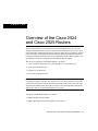
The Cisco 2524 and Cisco 2525 routers provide LAN and WAN access in a low-cost
modular router platform that can grow with your internetworking needs. The Cisco 2524
offers an Ethernet (attachment unit interface [AUI] or 10BaseT) LAN connection, and the
Cisco 2525 offers a Token Ring (shielded twisted-pair [STP] or unshielded twisted-pair
[UTP]) LAN connection. Both routers can accommodate up to three WAN modules—two
synchronous serial and one Integrated Services Digital Network (ISDN).
The choice of synchronous serial WAN modules is as follows:
•
•
•
•
2-wire switched 56-kbps data service unit/channel service unit (DSU/CSU)
4-wire 56/64-kbps DSU/CSU
Fractional T1/T1 DSU/CSU
Five-in-one synchronous serial
Note The five-in-one synchronous serial WAN module gets its name from the five types
of signaling it supports: EIA/TIA-232, EIA/TIA-449, V.35, X.21, and EIA-530. You can
order from Cisco Systems a DB-60 shielded serial transition cable. The router end of the
shielded serial transition cable has a DB-60 connector; the other end of the cable has the
appropriate connector for the standard interface you specify.
The choice of ISDN WAN modules is as follows:
•
•
ISDN Basic Rate Interface (BRI)
ISDN with integrated network termination 1 (NT1) device
Overview of the Cisco 2524 and Cisco 2525 Routers 1-1
Features
The ISDN WAN modules are designed so that you cannot insert them into the synchronous
serial WAN slots. A blank slot cover is installed over unused slots.
Features
The Cisco 2524 and Cisco 2525 routers include the following features:
•
•
•
•
Three slots for WAN modules
•
•
•
•
Nonvolatile random-access memory (NVRAM) for storing configuration information
One Ethernet (AUI or 10BaseT) interface on the Cisco 2524 router
One Token Ring (STP or UTP) interface on the Cisco 2525 router
Dynamic random-access memory (DRAM) for main system memory and shared
memory
Flash memory for running Cisco IOS software
EIA/TIA-232 console port for connecting a console terminal
EIA/TIA-232 auxiliary port for connecting a terminal or modem
Note EIA/TIA-232 and EIA/TIA-449 were known as recommended standards RS-232
and RS-449 before their acceptance as standards by the Electronic Industries Association
(EIA) and Telecommunications Industry Association (TIA).
1-2 Cisco 2524 and Cisco 2525 Router User Guide
Features
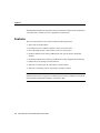
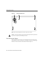
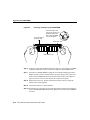
Figure 1-1 shows the front panel, which is the same for both routers.
Cisco 2524 and Cisco 2525 Front Panel
H1690
Figure 1-1
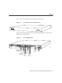
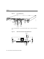
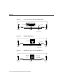
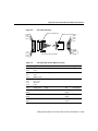
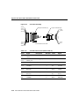
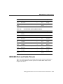
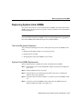
Figure 1-2 shows the rear panel of the Cisco 2524 router, and Figure 1-3 shows the rear
panel of the Cisco 2525 router.
SERIAL 0
SERIAL 1
Cisco 2524 Rear Panel
H5045
Figure 1-2
BRI 0
Ethernet AUI
port (DB-15)
LAN
Console
activity
port
LED
(RJ-45)
Ethernet 10BaseT
Auxiliary
link LED
port
port
(RJ-45)
(RJ-45)
On/off
switch
Power
Overview of the Cisco 2524 and Cisco 2525 Routers 1-3
Features
SERIAL 0
SERIAL 1
Cisco 2525 Rear Panel
H5271
Figure 1-3
BRI 0
Token Ring LAN
Console
port (DB-9) activity
port
LED
(RJ-45)
Token Ring
Auxiliary
in-ring LED
UTP
port
port
(RJ-45)
(RJ-45)
On/off
switch
Power
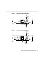
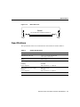
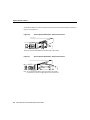
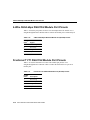
Figure 1-4 through Figure 1-9 show the WAN modules. Figure 1-10 shows the blank slot
cover.
Figure 1-4
2-Wire Switched 56-kbps DSU/CSU WAN Module
Transmit
LED
2-WIRE
56K
DSU/CSU
Captive
screw
CD
RJ-11
1-4 Cisco 2524 and Cisco 2525 Router User Guide
TX
LB
RX
AL
Carrier Alarm
LED
detect
LED
Receive
LED
H5046
Loopback
LED
Captive
screw
Features
Figure 1-5
4-Wire 56/64-kbps DSU/CSU WAN Module
Transmit
LED
4-WIRE
56K/64K
DSU/CSU
Captive
screw
CD
RJ-48S
Figure 1-6
TX
LB
RX
AL
Carrier Alarm
LED
detect
LED
Receive
LED
H5047
Loopback
LED
Captive
screw
Fractional T1/T1 DSU/CSU WAN Module
Transmit
LED
MON
JACK
IN
OUT
FTI/TI
DSU/CSU
Captive
screw
CD
Monitor
jack
TX
LB
RX
AL
NET
RJ-48C
Carrier Alarm
LED
detect
LED
Receive
LED
H5048
Loopback
LED
Captive
screw
Overview of the Cisco 2524 and Cisco 2525 Routers 1-5
Features
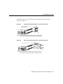
Figure 1-7
Five-in-One Synchronous Serial WAN Module
SERIAL
H5049
ACTIVITY
Captive
screw
Figure 1-8
DB-60
Serial
activity LED
Captive
screw
ISDN BRI WAN Module
ACTIVITY
S/T
Captive
screw
Captive
screw
ISDN BRI with Integrated NT1 WAN Module
ACT
ISDN-BRI
with NTI
U
Captive
screw
ISDN BRI
activity LED
RJ-45
1-6 Cisco 2524 and Cisco 2525 Router User Guide
NTI
H5051
Figure 1-9
RJ-45
H5050
ISDN-BRI
Captive
screw
Specifications
Figure 1-10
Blank Slot Cover
H5052
BLANK
Do not plug/unplug modules with power on.
Captive
screw
Captive
screw
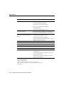
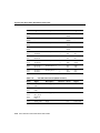
Specifications
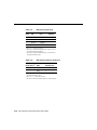
The specifications of the Cisco 2524 and Cisco 2525 routers are listed in Table 1-1.
Table 1-1
System Specifications
Description
Specification
Dimensions (H x W x D)
1.75 x 17.5 x 10.56" one rack unit
(4.44 x 44.45 x 26.82 cm)
Weight
10 lb (4.5 kg)
Input voltage, AC power supply
Current
Frequency
Power dissipation
100–240 VAC1
1.2–0.6A
50–60 Hz
40W (maximum), 135.5 Btus2/hr
Input voltage, DC power supply
Current
Power dissipation
40W, 40–72 VDC3
1.5–1.0A
40W (maximum), 135.5 Btus/hr
Processor
20-MHz Motorola 68EC030
Overview of the Cisco 2524 and Cisco 2525 Routers 1-7
Specifications
Description
Specification
WAN interface options
• 2-wire switched 56-kbps DSU/CSU (RJ-11)
• 4-wire 56/64-DSU/CSU (RJ-48S)
• Fractional T1/T1 DSU/CSU (RJ-48C)
• Five-in-one synchronous serial (DB-60)
• ISDN BRI (RJ-45)
• ISDN BRI with integrated NT1 (RJ-45)
LAN interface options
Cisco 2524: Ethernet AUI (DB-15) or 10BaseT (RJ-45)
Cisco 2525: Token Ring STP (DB-9) or UTP (RJ-45)
Synchronous serial interfaces
(five-in-one synchronous serial WAN
module)
• EIA/TIA-232, EIA/TIA-449, V.35, X.21
(NRZ/NRZI4 and DTE/DCE5 mode)
• EIA-530 (NRZ/NRZI and DTE mode)
• The five-in-one synchronous serial interface uses the
DB-60 connector at the chassis
Console and auxiliary ports
Asynchronous serial (RJ-45)
Operating environment
32–104°F (0–40°C)
Nonoperating temperature
–40–185°F (–40–85°C)
Operating humidity
5–95%, noncondensing
Noise level
34 dB6 @ 3' (0.914 m)
Regulatory compliance
• 2-wire switched 56-kbps DSU/CSU module: FCC
Class A, Part 15
• 4-wire 56/64-kbps DSU/CSU module: FCC Class A,
Part 15 and FCC Part 68
• Fractional T1/T1 DSU/CSU module: FCC Class A,
Part 15 and FCC Part 68
1. VAC = volts alternating current.
2. BTU = British thermal unit.
3. VDC = volts direct current.
4. NRZ = nonreturn to zero; NRZI = nonreturn to zero inverted.
5. DTE = data terminal equipment; DCE = data communications equipment.
6. dB = decibels.
1-8 Cisco 2524 and Cisco 2525 Router User Guide
FCC Part 68
FCC Part 68
The following text is required for FCC Part 68 regulatory compliance:
The equipment complies with Part 68 of the FCC rules. On the bottom of the equipment is
a label that shows the FCC registration number.
If the equipment causes harm to the telephone network, the telephone company may
temporarily discontinue service. If possible, advance notification is given; otherwise,
notification is given as soon as possible. The telephone company will advise the customer
of the right to file a complaint with the FCC.
The telephone company may make changes in its facility, equipment, operations, or
procedures that could affect the proper operation of the equipment; advance notification
and the opportunity to maintain uninterrupted service will be given.
If you experience difficulty with the Cisco 2524 or Cisco 2525 router, please contact Cisco
Systems at 800 553-NETS (6387) or 408 526-4000 for repair and warranty information. If
your equipment is causing harm to the telephone network, the telephone company may
request that you disconnect the equipment until the problem is resolved.
The module contains no user-serviceable parts.
An FCC-compliant telephone cord and a modular plug is provided with the equipment. The
equipment is designed to be connected to the telephone network or premises wiring using
an FCC-compatible modular jack that is Part 68 compliant.
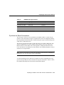
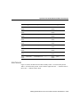
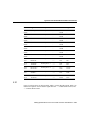
Table 1-2 lists information that may be required when applying to the local telephone
company for leased-line facilities.
Overview of the Cisco 2524 and Cisco 2525 Routers 1-9
FCC Part 68
Table 1-2
Information About Leased-Line Facilities
Module Type
Service Type
Digital Facility
Interface Code
Service
Order Code
Network
Jack
4-Wire 56/64-kbps
DSU/CSU WAN Module
2.4-kbps digital interface
04DU5-24
6.0F
RJ-48S
4.8-kbps digital interface
04DU5-48
6.0F
RJ-48S
9.6-kbps digital interface
04DU5-96
6.0F
RJ-48S
19.2-kbps digital interface
04DU5-19
6.0F
RJ-48S
38.4-kbps digital interface
04DU5-38
6.0F
RJ-48S
56-kbps digital interface
04DU5-56
6.0F
RJ-48S
64-kbps digital interface
04DU5-64
6.0F
RJ-48S
1.544-Mbps digital interface
04DU9-ISN
6.0N
RJ-48C
Fractional T1/T1
DSU/CSU WAN Module
1-10 Cisco 2524 and Cisco 2525 Router User Guide
2
CHAPT E R
Preparing to Install the
Cisco 2524 and Cisco 2525
Routers
This chapter describes the tasks you must perform before you begin to install the
Cisco 2524 and Cisco 2525 routers, and includes the following sections:
•
•
•
•
•
•
Safety Recommendations
General Site Requirements
Installation Checklist
Creating a Site Log
Preparing to Connect to a Network
Inspecting the System
Safety Recommendations
Follow these guidelines to ensure general safety:
•
•
•
•
Keep the chassis area clear and dust-free during and after installation.
•
Wear safety glasses if you are working under any conditions that might be hazardous to
your eyes.
•
Do not perform any action that creates a potential hazard to people or makes the
equipment unsafe.
Put the removed chassis cover in a safe place.
Keep tools away from walk areas where you and others could fall over them.
Do not wear loose clothing that could get caught in the chassis. Fasten your tie or scarf
and roll up your sleeves.
Preparing to Install the Cisco 2524 and Cisco 2525 Routers 2-1
Safety Recommendations
Warning Ultimate disposal of this product should be handled according to all national
laws and regulations. (To see translated versions of this warning, refer to the appendix
“Translated Safety Warnings.”)
Maintaining Safety with Electricity
Follow these guidelines when working on equipment powered by electricity.
Warning Before working on equipment that is connected to power lines, remove jewelry
(including rings, necklaces, and watches). Metal objects will heat up when connected to
power and ground and can cause serious burns or can weld the metal object to the terminals.
(To see translated versions of this warning, refer to the appendix “Translated Safety
Warnings.”)
•
Locate the emergency power-off switch for the room in which you are working. Then,
if an electrical accident occurs, you can act quickly to turn off the power.
•
Disconnect all power by turning off the power and unplugging the power cord before
doing the following:
— Installing or removing a chassis
— Working near power supplies
When installing the unit, the ground connection must always be made first and
disconnected last. (To see translated versions of this warning, refer to the appendix
“Translated Safety Warnings.”)
Warning
•
•
Do not work alone if potentially hazardous conditions exist.
Never assume that power is disconnected from a circuit. Always check.
2-2 Cisco 2524 and Cisco 2525 Router User Guide
Safety Recommendations
Warning Read the installation instructions before you connect the system to its power
source. (To see translated versions of this warning, refer to the appendix “Translated Safety
Warnings.”)
•
Look carefully for possible hazards in your work area, such as moist floors, ungrounded
power extension cables, frayed power cords, and missing safety grounds.
•
If an electrical accident occurs, proceed as follows:
— Use caution; do not become a victim yourself.
— Turn off power to the system.
— If possible, send another person to get medical aid. Otherwise, assess the condition
of the victim and then call for help.
— Determine if the person needs rescue breathing or external cardiac compressions;
then take appropriate action.
Preventing Electrostatic Discharge Damage
Electrostatic discharge (ESD) can damage equipment and impair electrical circuitry. ESD
damage occurs when electronic components are improperly handled and can result in
complete or intermittent failures.
Always follow ESD-prevention procedures when removing and replacing components.
Ensure that the chassis is electrically connected to earth ground. Wear an ESD-preventive
wrist strap, ensuring that it makes good skin contact. Connect the grounding clip to an
unpainted surface of the chassis frame to safely ground unwanted ESD voltages. To
properly guard against ESD damage and shocks, the wrist strap and cord must operate
effectively. If no wrist strap is available, ground yourself by touching the metal part of the
chassis.
Caution For safety, periodically check the resistance value of the antistatic strap, which
should be between 1 and 10 megohms (Mohms).
Preparing to Install the Cisco 2524 and Cisco 2525 Routers 2-3
General Site Requirements
General Site Requirements
This section describes the requirements your site must meet for safe installation and
operation of your system. Ensure that your site is properly prepared before beginning
installation.
Site Environment
The routers can be placed on a desktop or mounted in a rack or on a wall. The location of
the routers and the layout of your equipment rack or wiring room are extremely important
for proper system operation. Equipment placed too close together, inadequate ventilation,
and inaccessible panels can cause system malfunctions and shutdowns, and can make
router maintenance difficult.
When planning your site layout and equipment locations, keep in mind the precautions
described in the next section, “Preventive Site Configuration,” to help avoid equipment
failures and reduce the possibility of environmentally caused shutdowns. If you are
currently experiencing shutdowns or unusually high errors with your existing equipment,
these precautions may help you isolate the cause of failures and prevent future problems.
Preventive Site Configuration
The following precautions will help you plan an acceptable operating environment for your
router and will help you avoid environmentally caused equipment failures:
•
Electrical equipment generates heat. Ambient air temperature might not be adequate to
cool equipment to acceptable operating temperatures without adequate circulation.
Ensure that the room in which you operate your system has adequate air circulation.
•
Always follow the ESD-prevention procedures described in the section “Safety
Recommendations” earlier in this chapter to avoid damage to equipment. Damage from
static discharge can cause immediate or intermittent equipment failure.
•
Ensure that the chassis cover is secure. The chassis is designed to allow cooling air to
flow effectively within it. An open chassis allows air leaks, which may interrupt and
redirect the flow of cooling air from internal components.
2-4 Cisco 2524 and Cisco 2525 Router User Guide
General Site Requirements
Configuring Equipment Racks
The following tips will help you plan an acceptable equipment rack configuration:
•
Enclosed racks must have adequate ventilation. Ensure that the rack is not overly
congested because each unit generates heat. An enclosed rack should have louvered
sides and a fan to provide cooling air.
•
When mounting a chassis in an open rack, ensure that the rack frame does not block the
intake or exhaust ports. If the chassis is installed on slides, check the position of the
chassis when it is seated all the way into the rack.
•
In an enclosed rack with a ventilation fan in the top, excessive heat generated by
equipment near the bottom of the rack can be drawn upward and into the intake ports of
the equipment above it in the rack. Ensure that you provide adequate ventilation for
equipment at the bottom of the rack.
•
Baffles can help to isolate exhaust air from intake air, which also helps to draw cooling
air through the chassis. The best placement of the baffles depends on the airflow patterns
in the rack, which are found by experimenting with different arrangements.
Power Supply Considerations
Check the power at your site to ensure that you are receiving “clean” power (free of spikes
and noise). Install a power conditioner if necessary.
Warning The device is designed to work with TN power systems. (To see translated
versions of this warning, refer to the appendix “Translated Safety Warnings.”)
Preparing to Install the Cisco 2524 and Cisco 2525 Routers 2-5
Installation Checklist
The router’s AC power supply includes the following features:
•
•
Autoselects either 110V or 220V operation.
All units include a 6-foot (1.8-meter) electrical power cord. (A label near the power cord
indicates the correct voltage, frequency, current draw, and power dissipation for the
unit.)
Warning This product relies on the building’s installation for short-circuit (overcurrent)
protection. Ensure that a fuse or circuit breaker no larger than 120 VAC, 15A U.S.
(240 VAC, 10A international) is used on the phase conductors (all current-carrying
conductors). (To see translated versions of this warning, refer to the appendix “Translated
Safety Warnings.”)
The Cisco 2524 offers a direct current (DC) power supply. See the section “DC Power
Specifications” in the chapter “Installing the Cisco 2524 and Cisco 2525 Routers” for more
information.
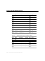
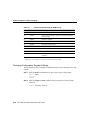
Installation Checklist
The Installation Checklist lists the procedures for initial hardware installation of a new
router. Make a copy of this checklist and mark the entries as you complete each procedure.
Include a copy of the checklist for each system in your Site Log. (See the next section,
“Creating a Site Log.”)
2-6 Cisco 2524 and Cisco 2525 Router User Guide
Installation Checklist
Installation checklist for site______________________________________________
Router name__________________________________________________________
Task
Verified by
Date
Installation checklist copied
Background information placed in Site Log
Site power voltages verified
Required tools available
Additional equipment available
Router received
Optional UniverCD or printed documentation
received
Chassis components verified
Initial electrical connections established
ASCII terminal or PC attached to console port
Signal distance limits verified
Startup sequence steps completed
Initial system operation verified
Software image verified
Preparing to Install the Cisco 2524 and Cisco 2525 Routers 2-7
Creating a Site Log
Creating a Site Log
The Site Log provides a record of all actions relevant to the router. Keep it near the chassis
where anyone who installs or maintains the router has access to it. Use the Installation
Checklist (see the previous section, “Installation Checklist”) to verify steps in the
installation and maintenance of your router. Site Log entries might include the following:
•
Installation progress—Make a copy of the Installation Checklist and insert it into the
Site Log. Make entries on the checklist as you complete each procedure.
•
Upgrade and maintenance procedures—Use the Site Log as a record of ongoing system
maintenance and expansion. Each time a procedure is performed on the router, update
the Site Log to reflect the following:
— Configuration changes
— Changes and updates to Cisco IOS software
— Maintenance schedules and requirements
— Corrective maintenance procedures performed
— Intermittent problems
— Related comments and notes
Preparing to Connect to a Network
When setting up your router, consider distance limitations and potential electromagnetic
interference (EMI) as defined by the EIA.
Warning The Ethernet 10BaseT, Token Ring, serial, console, and auxiliary ports contain
safety extra-low voltage (SELV) circuits. BRI circuits are treated like telephone-network
voltage (TNV) circuits. Avoid connecting SELV circuits to TNV circuits. (To see translated
versions of this warning, refer to the appendix “Translated Safety Warnings.”)
2-8 Cisco 2524 and Cisco 2525 Router User Guide
Preparing to Connect to a Network
2-Wire Switched 56-kbps DSU/CSU WAN Module
The 2-wire switched 56-kbps DSU/CSU WAN module includes an RJ-11 port for
connection to a WAN. Cables are not included with the modules; however, port pinouts are
listed in the section “Fractional T1/T1 DSU/CSU Module Port Pinouts” in the appendix
“Cabling Specifications for the Cisco 2524 and Cisco 2525 Routers.”
Warning Network hazardous voltages are present in the BRI, fractional T1/T1, and
switched 56 cables. If you detach the cable, detach the end away from the router first to
avoid possible electric shock. Network hazardous voltages are also present in the area of
the BRI (RJ-45), fractional T1/T1 (RJ-48C), and switched 56 (RJ-11 or RJ-48S) ports,
regardless of whether power is OFF or ON. (To see translated versions of this warning, refer
to the appendix “Translated Safety Warnings.”)
This card is intended to be installed in UL- and CSA-certified equipment in the
field by the user in the manufacturer’s defined operator access area. Check the equipment
manufacturer to verify/confirm that your equipment is suitable for user-installed
application cards. (To see translated versions of this warning, refer to the appendix
“Translated Safety Warnings.”)
Warning
Table 2-2 lists network specifications to consider before connecting the module to a
network.
Table 2-1
2-Wire Switched 56-kbps DSU/CSU WAN Module Network
Specifications
Description
Specification
Loop rates
56 kbps
Data rates
56 kbps
Line requirements
Northern Telecom Datapath
Technology, Bellcore TR-EOP-000277
Receiver sensitivity
–42 dB at 80 kHz1
1. kHz = kilohertz.
Preparing to Install the Cisco 2524 and Cisco 2525 Routers 2-9
Preparing to Connect to a Network
4-Wire 56/64-kbps DSU/CSU WAN Module
The 4-wire 56/64-kbps DSU/CSU WAN module includes an RJ-48S port for connection to
a WAN. Cables are not included with the module; however, port pinouts are listed in the
section “4-Wire 56/64-kbps DSU/CSU Module Port Pinouts” in the appendix “Cabling
Specifications for the Cisco 2524 and Cisco 2525 Routers.
Warning Network hazardous voltages are present in the BRI, fractional T1/T1, and
switched 56 cables. If you detach the cable, detach the end away from the router first to
avoid possible electric shock. Network hazardous voltages are also present in the area of
the BRI (RJ-45), fractional T1/T1 (RJ-48C), and switched 56 (RJ-11 or RJ-48S) ports,
regardless of whether power is OFF or ON. (To see translated versions of this warning, refer
to the appendix “Translated Safety Warnings.”)
This card is intended to be installed in UL- and CSA-certified equipment in the
field by the user in the manufacturer’s defined operator access area. Check the equipment
manufacturer to verify/confirm that your equipment is suitable for user-installed
application cards. (To see translated versions of this warning, refer to the appendix
“Translated Safety Warnings.”)
Warning
Table 2-2 lists network specifications to consider before connecting the module to a
network.
2-10 Cisco 2524 and Cisco 2525 Router User Guide
Preparing to Connect to a Network
Table 2-2
4-Wire 56/64-kbps DSU/CSU Module Network Specifications
Description
Specification
Loop rates
DDS1: 2.4, 4.8, 9.6, 19.2, 38.4, 56, and 64 kbps
Switched 56: 56 kbps
Data rates
2.4, 4.8, 9.6, 19.2, 56, and 64 kbps
Line requirements
DDS: AT&T Publication 62310
Switched 56: AT&T Publication 41458, Sprint TS-0046
Receiver sensitivity
–45 dB at all loop rates
1. DDS = digital data system (leased or dedicated lines).
Fractional T1/T1 DSU/CSU WAN Module
The fractional T1/T1 DSU/CSU WAN module includes an RJ-48C port. Cables are not
included with the module; however, port pinouts are listed in the section “Fractional T1/T1
DSU/CSU Module Port Pinouts” in the appendix “Cabling Specifications for the
Cisco 2524 and Cisco 2525 Routers.”
Warning Network hazardous voltages are present in the BRI, fractional T1/T1, and
switched 56 cables. If you detach the cable, detach the end away from the router first to
avoid possible electric shock. Network hazardous voltages are also present in the area of
the BRI (RJ-45), fractional T1/T1 (RJ-48C), and switched 56 (RJ-11 or RJ-48S) ports,
regardless of whether power is OFF or ON. (To see translated versions of this warning, refer
to the appendix “Translated Safety Warnings.”)
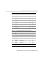
Table 2-3 lists network specifications to consider before connecting the fractional T1/T1
DSU/CSU WAN module to a network.
Preparing to Install the Cisco 2524 and Cisco 2525 Routers 2-11
Preparing to Connect to a Network
Table 2-3
Fractional T1/T1 DSU/CSU WAN Module Network Specifications
Description
Specification
Line rate
1.544 Mbps1
Data rates
n x 56 or n x 64 kbps, where n = 1 to 242
Standards
AT&T Publication 62411, 54016, and 43801
1. Mbps = megabits per second.
2. The T1 interface is not channelized.
ISDN Connections
Use an appropriate cable (not included) to connect the router directly to an ISDN. (See
Table 2-4.) Refer to the section “ISDN BRI Port and Cable Pinouts” in the appendix
“Cabling Specifications for the Cisco 2524 and Cisco 2525 Routers” for port and cable
pinouts.
Note the following warnings:
Warning Network hazardous voltages are present in the BRI, fractional T1/T1, and
switched 56 cables. If you detach the cable, detach the end away from the router first to
avoid possible electric shock. Network hazardous voltages are also present in the area of
the BRI (RJ-45), fractional T1/T1 (RJ-48C), and switched 56 (RJ-11 or RJ-48S) ports,
regardless of whether power is OFF or ON. (To see translated versions of this warning, refer
to the appendix “Translated Safety Warnings.”)
Warning The ISDN connection is regarded as a source of voltage that should be
inaccessible to user contact. Do not attempt to tamper with or open any public telephone
operator (PTO)-provided equipment or connection hardware. Any hardwired connection
(other than by nonremovable, connect-one-time-only lug) must be made only by PTO staff
or suitably trained engineers. (To see translated versions of this warning, refer to the
appendix “Translated Safety Warnings.”)
Table 2-4 lists the specifications for ISDN BRI cables.
2-12 Cisco 2524 and Cisco 2525 Router User Guide
Preparing to Connect to a Network
Table 2-4
ISDN BRI Cable Specifications
Specification
High-Capacitance Cable
Low-Capacitance Cable
Resistance (at 96 kHz)
160 ohms/km
160 ohms/km
Capacitance (at 1 kHz)
1
120 nF /km
30 nF/km
Impedance (96 kHz)
75 ohms
150 ohms
Wire diameter
0.024" (0.6 mm)
0.024" (0.6 mm)
Distance limitation
32.8' (10 m)
32.8' (10 m)
1. nF = nanoFarad.
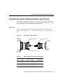
Synchronous Serial Connections
The serial port on the five-in-one synchronous serial WAN module is a 60-pin, D-type
connector. The synchronous serial port (except the EIA-530) can be configured as DTE or
DCE, depending on the attached cable. All DTE serial ports require external clocking from
a DSU/CSU or other DCE device.
You must use a special serial cable to connect the router to a modem or DSU/CSU. This
cable is available from Cisco and is usually ordered with the system. The cable uses a
DB-60 connector on the chassis end. See the appendix “Cabling Specifications for the
Cisco 2524 and Cisco 2525 Routers” for cable pinouts. For ordering information, contact a
customer service representative.
Note Because of the small size of the pins on the DB-60 serial connector, attempting to
manufacture your own serial cables is not recommended.
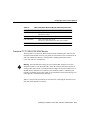
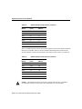
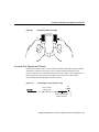
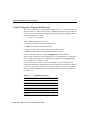
As with all signaling systems, EIA/TIA-232 signals can travel a limited distance at any
given bit rate; generally, the slower the data rate, the greater the distance. Table 2-5 shows
the standard relationship between baud rate and maximum distance.
Preparing to Install the Cisco 2524 and Cisco 2525 Routers 2-13
Preparing to Connect to a Network
Table 2-5
EIA/TIA-232 Speed and Distance Limitations
Data Rate
(Baud)
Distance
(Feet)
Distance
(Meters)
2400
200
60
4800
100
30
9600
50
15
19200
50
15
38400
50
15
57600
25
7.6
115200
12
3.7
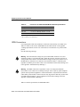
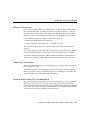
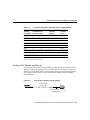
The use of balanced drivers allows EIA/TIA-449 signals to travel greater distances than the
EIA/TIA-232 standard. Table 2-6 lists the standard relationship between baud rate and
maximum distance for EIA/TIA-449 signals. These limits are also valid for V.35 and X.21.
Table 2-6
EIA/TIA-449 Speed and Distance Limitations
Data Rate
(Baud)
Distance
(Feet)
Distance
(Meters)
2400
4,100
1,250
4800
2,050
625
9600
1,025
312
19200
513
156
38400
256
78
56000
102
31
T1
50
15
The EIA/TIA-449 and V.35 interfaces support data rates up to 2.048 Mbps.
Exceeding this maximum could result in loss of data and is not recommended.
Caution
2-14 Cisco 2524 and Cisco 2525 Router User Guide
Preparing to Connect to a Network
Ethernet Connections
On the Cisco 2524 router, there are two Ethernet ports, an AUI port and a 10BaseT port, on
the rear panel of the router. To connect your router to an Ethernet network, you can use
either the Ethernet AUI or 10BaseT port, but not both. The router automatically detects
which port is in use. (If you attempt to use both ports, only the 10BaseT port will work.)
Use the following equipment to connect to the Ethernet AUI port:
•
•
Ethernet AUI cable connected to a transceiver
Ethernet transceiver connected directly to the router’s AUI port
The connection to the AUI port can be attached using either a slide-latch or jackscrew
connector.
The distance limitations for the IEEE 802.3 (10Base5 coaxial cable) specification indicate
a maximum segment distance of 1,640 feet (500 m) at a transmission rate of 10 Mbps.
The distance limitations for Ethernet 10BaseT indicate a maximum segment distance of
328 feet (100 m); Ethernet 10Base2 has a maximum segment distance of 607 feet (185 m).
Token Ring Connections
On the Cisco 2525 router, there are two Token Ring ports, a STP port and a UTP port, on
the rear panel of the router.
The distance limitations for the IEEE 802.5 specification indicate a maximum segment
distance of 328 feet (100 m) at a transmission rate of 4 or 16 Mbps for UTP cabling. The
distance limitation is 1,640 feet (500 m) for STP cabling.
Console and Auxiliary Port Considerations
Both routers include an asynchronous serial console and auxiliary port. The console and
auxiliary ports provide access to the router either locally (with a console terminal) or
remotely (with a modem). This section discusses important cabling information to consider
before connecting a console terminal (an ASCII terminal or PC running terminal emulation
software) to the console port or modem to the auxiliary port.
Preparing to Install the Cisco 2524 and Cisco 2525 Routers 2-15
Preparing to Connect to a Network
The main difference between the console and auxiliary ports is that the auxiliary port
supports flow control and the console port does not. Flow control paces the transmission of
data between a sending device and a receiving device. Flow control ensures that the
receiving device can absorb the data sent to it before the sending device sends more. When
the buffers on the receiving device are full, a message is sent to the sending device to
suspend transmission until the data in the buffers has been processed. Because the auxiliary
port supports flow control, it is ideally suited for use with the high-speed transmissions of
a modem. Console terminals transmit at slower speeds than modems; therefore, the console
port is ideally suited for use with console terminals.
Console Port Connections
Both routers include an EIA/TIA-232 asynchronous serial console port (RJ-45). Depending
on the cable and the adapter used, this port will appear as a DTE or DCE device at the end
of the cable. Your router comes with cables and adapters to connect a console terminal (an
ASCII terminal or PC running terminal emulation software) to the console port. To connect
an ASCII terminal to the console port, use the RJ-45 roll-over cable with the female
RJ-45-to-DB-25 adapter (labeled Terminal). To connect a PC running terminal emulation
software to the console port, use the RJ-45 roll-over cable with the female RJ-45-to-DB-9
adapter (labeled Terminal). The default parameters for the console port are 9600 baud,
8 data bits, no parity, and 2 stop bits. The console port does not support flow control. For
detailed information about installing a console terminal, see the section “Connecting to the
Console Port” in the chapter “Installing the Cisco 2524 and Cisco 2525 Routers.” See the
appendix “Cabling Specifications for the Cisco 2524 and Cisco 2525 Routers” for cable
and port pinouts.
Auxiliary Port Connections
Both routers include an EIA/TIA-232 asynchronous serial auxiliary port (RJ-45) that
supports flow control. Depending on the cable and the adapter used, this port will appear as
a DTE or DCE device at the end of the cable. Your router comes with a cable and an adapter
to connect a modem to the auxiliary port. To connect a modem to the auxiliary port, use the
RJ-45 roll-over cable with the male RJ-45-to-DB-25 adapter (labeled Modem). For detailed
information about connecting devices to the auxiliary port, see the section “Connecting the
Console Terminal and Modem” in the chapter “Installing the Cisco 2524 and Cisco 2525
Routers.” See the appendix “Cabling Specifications for the Cisco 2524 and Cisco 2525
Routers” for cable and port pinouts.
2-16 Cisco 2524 and Cisco 2525 Router User Guide
Inspecting the System
Inspecting the System
Do not unpack the router until you are ready to install it. If the final installation site will not
be ready for some time, keep the chassis in its shipping container to prevent accidental
damage. When you have determined where you want the router installed, proceed with
unpacking it.
The router, cables, UniverCD or printed publications, and any optional equipment you
ordered might be shipped in more than one container. When you unpack each shipping
container, check the packing list to ensure that you received all of the following items:
•
•
•
•
Cisco 2524 or Cisco 2525 router
6-foot (1.8-meter) power cord
Jackscrews for the AUI connector (Cisco 2524 router only)
Console and auxiliary cable kit, which includes the following items:
— RJ-45-to-RJ-45 roll-over cable
— RJ-45-to-DB-9 female DTE adapter (labeled Terminal)
— RJ-45-to-DB-25 female DTE adapter (labeled Terminal)
— RJ-45-to-DB-25 male DCE adapter (labeled Modem)
•
•
Optional equipment (such as network interface cables and WAN modules)
Cisco Information Packet publication, UniverCD, and optional printed publications
specified on your order
Inspect all items for shipping damage. If anything appears to be damaged, or if you
encounter problems when installing or configuring your system, contact a customer service
representative.
Preparing to Install the Cisco 2524 and Cisco 2525 Routers 2-17
Inspecting the System
2-18 Cisco 2524 and Cisco 2525 Router User Guide
3
CHAPT E R
Installing the Cisco 2524 and
Cisco 2525 Routers
This chapter guides you through the installation of the Cisco 2524 and Cisco 2525 routers
and includes the following sections:
•
•
•
•
•
•
Required Tools and Parts
Setting Up the Chassis
Connecting the DC Power Supply
Connecting to the Network
Connecting the Console Terminal and Modem
What to Do after Installing the Router Hardware
Warning Only trained and qualified personnel should be allowed to install or replace this
equipment. (To see translated versions of this warning, refer to the appendix “Translated
Safety Warnings.”)
Installing the Cisco 2524 and Cisco 2525 Routers 3-1
Required Tools and Parts
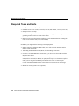
Required Tools and Parts
Following are the tools and parts required to install the router:
•
•
•
Flat-blade screwdrivers: small, 3/16-inch (0.476 cm) and medium, 1/4-inch (0.625 cm)
•
Rubber feet for setting the router on a desktop, or rack-mount brackets for mounting the
router in a rack or on a wall (screws not included)
•
An interface cable (not included) for each LAN and WAN interface
ESD-preventive wrist strap
A thread-forming screw (which is not included), to attach a ground wire to the protective
grounding terminal on the rear panel of the chassis
In addition, you might need the following external equipment:
•
Ethernet transceiver, Ethernet 10BaseT hub, or PC with a network interface card for
Ethernet LAN connections.
•
•
Token Ring media attachment unit (MAU) for Token Ring connections.
•
Console terminal (an ASCII terminal or a PC running terminal emulation software)
configured for 9600 baud, 8 data bits, no parity, and 2 stop bits. A terminal is required
unless you are using the AutoInstall procedure. See the section “Connecting the
Console Terminal and Modem” later in this chapter for instructions on connecting a
console terminal.
•
Modem for remote system access (optional).
NT1 device for ISDN BRI WAN connections, if you do not have the module with the
integrated NT1 device.
3-2 Cisco 2524 and Cisco 2525 Router User Guide
Setting Up the Chassis
Setting Up the Chassis
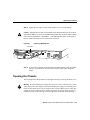
You can set the chassis on a desktop, install it in a rack, or mount it on a wall or other flat
surface. Use the procedure in this section that best fits the needs of your network.
Setting the Chassis on a Desktop
Before setting the router on a desktop, shelf, or other flat, secure surface, perform the
following steps to install the rubber feet:
Step 1 Locate the rubber feet on the black adhesive strip that shipped with the chassis.
(See Figure 3-1.)
Figure 3-1
Identifying the Rubber Feet
H4796
Rubber feet (5)
Black adhesive strip
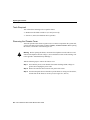
Step 2 Place the router upside down on a smooth, flat surface.
Step 3 Peel off the rubber feet from the black adhesive strip and place them adhesive-side
down onto the five round, recessed areas on the bottom of the chassis, as shown in
Figure 3-2.
Installing the Cisco 2524 and Cisco 2525 Routers 3-3
Setting Up the Chassis
Figure 3-2
Installing the Rubber Feet
H4795
Fan
Step 4 Place the router right-side up on a flat, smooth, secure surface.
Do not place anything on top of the router that weighs more than 10 pounds (4.5
kg). Excessive weight on top could damage the chassis.
Caution
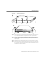
Rack-Mounting the Chassis
This section describes the procedures for rack-mounting the chassis. The chassis comes
with a bracket for use with a 19-inch rack or, if specified in your order, an optional larger
bracket for use with a 24-inch rack. The brackets are shown in Figure 3-3.
3-4 Cisco 2524 and Cisco 2525 Router User Guide
Setting Up the Chassis
Identifying the Brackets
Bracket for use
with a 19-inch rack
Bracket for use
with a 24-inch rack
H4201
Figure 3-3
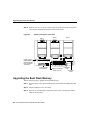
Attaching the Brackets
To install the chassis in a rack with the front panel forward, attach the brackets as shown in
Figure 3-4 or Figure 3-5.
19-Inch Bracket Installation—Front Panel Forward
SERIES
H1706
Figure 3-4
Note: The second bracket attaches to the other side of the chassis.
Figure 3-5
24-Inch Bracket Installation—Front Panel Forward
H3893
SERIES
Note: The second bracket attaches to the other side of the chassis.
Installing the Cisco 2524 and Cisco 2525 Routers 3-5
Setting Up the Chassis
To install the chassis in a rack with the rear panel forward, attach the brackets as shown in
Figure 3-6 or Figure 3-7.
Figure 3-6
19-Inch Bracket Installation—Rear Panel Forward
Input: 100-240VAC
Freq: 50.60 Hz
Current: 1.2-0.6A
Watts: 40W
H1704
1
0
Note: The second bracket attaches to the other side of the chassis.
Figure 3-7
24-Inch Bracket Installation—Rear Panel Forward
Input: 100-240VAC
Freq: 50.60 Hz
Current: 1.2-0.6A
Watts: 40W
0
H3894
1
Note: The second bracket attaches to the other side of the chassis.
The brackets can also be installed with the front panel forward.
3-6 Cisco 2524 and Cisco 2525 Router User Guide
Setting Up the Chassis
To install the chassis in a center-mount telco rack, attach the brackets as shown in
Figure 3-8 or Figure 3-9.
Figure 3-8
Telco 19-Inch Bracket Installation—Rear Panel Forward
Input: 100-240VAC
Freq: 50.60 Hz
Current: 1.2-0.6A
Watts: 40W
H1705
1
0
Note: The second bracket attaches to the other side of the chassis.
The brackets can also be installed with the front panel forward.
Figure 3-9
Telco 24-Inch Bracket Installation—Rear Panel Forward
Input: 100-240VAC
Freq: 50.60 Hz
Current: 1.2-0.6A
Watts: 40W
1
H3891
0
Note: The second bracket attaches to the other side of the chassis.
The brackets can also be installed with the front panel forward.
Installing the Cisco 2524 and Cisco 2525 Routers 3-7
Setting Up the Chassis
Installing in a Rack
After the brackets are secured to the chassis, you can rack-mount the chassis. Using the
screws you provide, attach the chassis to the rack as shown in Figure 3-10 or Figure 3-11.
Figure 3-10
Attaching the Chassis to the 19-Inch Rack—Rear Panel Forward
Input: 100-240VAC
Freq: 50.60 Hz
Current: 1.2-0.6A
Watts: 40W
1
H1719
0
Figure 3-11
Note: The second bracket attaches to the
rack at the other side of the chassis.
The brackets can also be installed
with the front panel forward.
Attaching the Chassis to the 24-Inch Rack—Rear Panel Forward
Input: 100-240VAC
Freq: 50.60 Hz
Current: 1.2-0.6A
Watts: 40W
1
Note: The second bracket attaches to the
rack at the other side of the chassis.
The brackets can also be installed
with the front panel forward.
H3892
0
3-8 Cisco 2524 and Cisco 2525 Router User Guide
Setting Up the Chassis
Wall-Mounting the Chassis
Use the smaller brackets (for use with a 19-inch rack) to wall-mount the chassis. The
smaller brackets provide the most stable position for the chassis.
Take the following steps to wall-mount the chassis:
Step 1 Attach the brackets as shown in Figure 3-12.
Figure 3-12
Attaching the Wall-Mount Brackets
Input: 100-240VAC
Freq: 50/60 Hz
Current: 1.2-0.6A
Watts: 40W
H1714
1
0
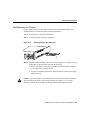
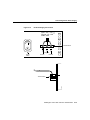
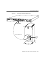
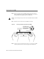
Step 2 Attach the chassis assembly to the wall as shown in Figure 3-13, using screws and
anchors that you provide. We recommend the following:
•
For the best support of the chassis and cables, attach the brackets so that the
screws align with a vertical wall stud.
•
For the best ventilation of the chassis, mount the chassis with the power supply
and fan at the top.
Caution To prevent the chassis from pulling away from the wall when cables are attached,
align the brackets and screws with a vertical wall stud. (See Figure 3-13.) To ensure
adequate ventilation, make sure there is clearance between the router and the wall.
Installing the Cisco 2524 and Cisco 2525 Routers 3-9
Setting Up the Chassis
Wall-Mounting the Chassis
H5367
SERIAL 0
SERIAL 1
BRI 0
Figure 3-13
3-10 Cisco 2524 and Cisco 2525 Router User Guide
Connecting the DC Power Supply
Connecting the DC Power Supply
The Cisco 2524 router offers an optional direct current (DC) power supply (not available
with the Cisco 2525 router). This section describes the DC power supply specifications and
wiring.
Warning This unit is intended for installation in restricted access areas. (To see translated
versions of the warning, refer to the appendix “Translated Safety Warnings.”)
DC Power Specifications
The DC power supply is intended for use in DC operating environments. Table 3-1 lists the
power supply specifications.
Table 3-1
DC Power Supply Specifications
Description
Design
Specification
Power (input)
40W, –40 to –72 VDC
Wire gauge for power connections
14 AWG1
1. AWG = American Wire Gauge.
Installing the Cisco 2524 and Cisco 2525 Routers 3-11
Connecting the DC Power Supply
Wiring the DC Power Supply
If you ordered a Cisco 2524 router with a DC power supply, follow the directions in this
section to wire the terminal block.
Warning Before performing any of the following procedures, ensure that power is
removed from the DC circuit. To ensure that all power is OFF, locate the circuit breaker on
the panel board that services the DC circuit, switch the circuit breaker to the OFF position,
and tape the switch handle of the circuit breaker in the OFF position. (To see translated
versions of this warning, refer to the appendix “Translated Safety Warnings.”)
Note This product is intended for installation in restricted access areas and is approved for
use with copper conductors only. The installation must comply with all applicable codes.
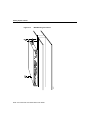
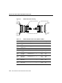
Figure 3-14 shows the DC power supply terminal block. Take the following steps to wire
the terminal block:
Step 1 Attach the appropriate lugs at the wire end of the power supply cord.
Step 2 Wire the DC power supply to the terminal block, as shown in Figure 3-14.
Warning The illustration shows the DC power supply terminal block. Wire the DC power
supply using the appropriate lugs at the wiring end, as illustrated. The proper wiring
sequence is ground to ground, positive to positive (line to L), and negative to negative
(neutral to N). Note that the ground wire should always be connected first and disconnected
last. (To see translated versions of this warning, refer to the appendix “Translated Safety
Warnings.”)
3-12 Cisco 2524 and Cisco 2525 Router User Guide
Connecting the DC Power Supply
Figure 3-14
DC Power Supply Connections
Input: –40– –72V
Current: 1.5 –1.0A
Watts: 40W
Terminal block
Ground
Negative
Positive
Terminal block
H2679
On/off
switch
Installing the Cisco 2524 and Cisco 2525 Routers 3-13
Connecting to the Network
Warning When stranded wiring is required, use approved wiring terminations, such as
closed-loop or spade-type with upturned lugs. These terminations should be the appropriate
size for the wires and should clamp both the insulation and conductor. (To see translated
versions of this warning, refer to the appendix “Translated Safety Warnings.”)
Caution Do not overtorque the terminal block captive thumbscrew or terminal block
contact screws. The recommended torque is 8.2 0.4 inch-lb.
Warning After wiring the DC power supply, remove the tape from the circuit breaker
switch handle and reinstate power by moving the handle of the circuit breaker to the ON
position. (To see translated versions of this warning, refer to the appendix “Translated
Safety Warnings.”)
Connecting to the Network
This section explains how to connect the router to your network, using the Ethernet (AUI
or 10BaseT) or Token Ring (STP or UTP) ports or the WAN modules.
Warning Do not work on the system or connect or disconnect cables during periods of
lightning activity. (To see translated versions of this warning, refer to the appendix
“Translated Safety Warnings.”)
Connecting to an Ethernet Network
If you have a Cisco 2524 router, it includes both an Ethernet AUI port and a 10BaseT port.
To connect your router to an Ethernet network, you can use either the Ethernet AUI or
10BaseT port, but not both. The first port connected will work. (If you attempt to use both
ports, only the 10BaseT port will work.)
3-14 Cisco 2524 and Cisco 2525 Router User Guide
Connecting to the Network
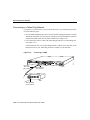
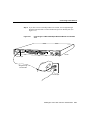
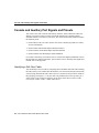
You can connect the router to your Ethernet network in one of the following ways:
•
Use an Ethernet AUI cable to connect the Ethernet AUI port to an Ethernet transceiver.
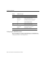
(See Figure 3-15.)
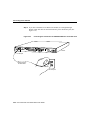
•
Use a straight-through 10BaseT cable to connect the 10BaseT port to a 10BaseT hub.
(See Figure 3-16.)
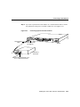
•
Use a crossover 10BaseT cable to connect the 10BaseT port to a PC network interface
card. (See Figure 3-17.)
Note If your Ethernet connection requires jackscrews, remove the slide-latch assembly
from the AUI connector and attach the jackscrews provided.
Connecting to an Ethernet Transceiver
H5368
Figure 3-15
SERIAL 0
SERIAL 1
Ethernet
AUI cable
(not supplied)
Ethernet
transceiver
BRI 0
Ethernet AUI port
DB-15 connector
(with jackscrews
or slide-latch)
Router
BNC connector
To thin
Ethernet
network
To thin
Ethernet
network
Installing the Cisco 2524 and Cisco 2525 Routers 3-15
Connecting to the Network
Connecting to a 10BaseT Hub
H5494
Figure 3-16
SERIAL 0
SERIAL 1
BRI 0
Router
Ethernet 10BaseT
port (RJ-45)
10BaseT hub
AUI
8
7
1
Straight-through
10BaseT cable
3-16 Cisco 2524 and Cisco 2525 Router User Guide
Connecting to the Network
Figure 3-17
BRI 0
Router
Ethernet 10BaseT
port (RJ-45)
PC
OK
ETH
Crossover 10BaseT cable
Network
interface
card
LAN
H5370
SERIAL 1
SER 0
SERIAL 0
Connecting to a PC Network Interface Card
Installing the Cisco 2524 and Cisco 2525 Routers 3-17
Connecting to the Network
Connecting to a Token Ring Network
If you have a Cisco 2524 router, you can connect the router to your Token Ring network in
one of the following ways:
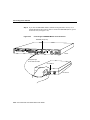
•
Use a shielded Token Ring lobe cable to connect the Token Ring port (DB-9) to a media
attachment unit (MAU). To ensure agency compliance with electromagnetic emissions
requirements (EMI), make sure the cable is shielded. (See Figure 3-18.)
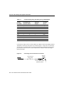
•
Use a twisted-pair cable to connect the Token Ring port (RJ-45) to a Token Ring hub.
(See Figure 3-19.)
If the transmission rate of your Token Ring network is 4 Mbps, use a UTP cable. If the
transmission rate of your Token Ring network is 16 Mbps, use an STP cable.
Connecting to a MAU
SERIAL 0
Token Ring
lobe cable
(not provided)
SERIAL 1
H5371
Figure 3-18
BRI 0
DB-9Token Ring
port connector
MAU
Standard IEEE
802.5 connector
3-18 Cisco 2524 and Cisco 2525 Router User Guide
Router
Connecting to the Network
Connecting to a Token Ring Hub
H5949
Figure 3-19
SERIAL 0
SERIAL 1
BRI 0
Router
Token Ring
port (RJ-45)
Token Ring hub
DB-9
8
7
1
UTP
cable
Connecting to a WAN
Although the illustrations in this section show the Cisco 2524 router, the procedures are the
same for both the Cisco 2524 and Cisco 2525 routers.
Warning Do not work on the system or connect or disconnect cables during periods of
lightning activity. (To see translated versions of this warning, refer to the appendix
“Translated Safety Warnings.”)
Installing the Cisco 2524 and Cisco 2525 Routers 3-19
Connecting to the Network
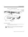
Take the following steps to connect the router to your WAN:
Step 1 If you have a 2-wire switched 56-kbps module, use a straight-through
RJ-11-to-RJ-11 cable to connect the RJ-11 port to an RJ-11 jack. (See
Figure 3-20.)
Connecting the 2-Wire Switched 56-kbps DSU/CSU Module to an
RJ-11 Jack
H5260
Figure 3-20
2-WIRE
56K
DSU/CSU
TX LB
CD
RX AL
SERIAL 0
SERIAL 1
BRI 0
Router
RJ-11 port
Straight-through
RJ-11 cable
RJ-11 jack
3-20 Cisco 2524 and Cisco 2525 Router User Guide
Connecting to the Network
Step 2 If you have a 4-wire 56/64-kbps DSU/CSU module, use a straight-through
RJ-48S-to-RJ-48S cable to connect the RJ-48S port to an RJ-48S jack. (See
Figure 3-21.)
Connecting the 4-Wire 56/64-kbps DSU/CSU Module to an RJ-48S
Jack
H5261
Figure 3-21
4-WIRE
56K/64K
DSU/CSU
TX LB
CD
RX AL
SERIAL 0
SERIAL 1
BRI 0
Router
RJ-48S port
Straight-through
RJ-48S cable
RJ-48S jack
Installing the Cisco 2524 and Cisco 2525 Routers 3-21
Connecting to the Network
Step 3 If you have a fractional T1/T1 DSU/CSU module, use a straight-through
RJ-48C-to-RJ-48C cable to connect the RJ-48C port to an RJ-48C jack. (See
Figure 3-22.)
Connecting the Fractional T1/T1 DSU/CSU Module to an RJ-48C Jack
H5262
Figure 3-22
MON JACK
TX LB
FTI/TI
DSU/CSU
CD
RX AL
SERIAL 0
SERIAL 1
Router
BRI 0
RJ-48C port
Straight-through
RJ-48C cable
RJ-48C jack
3-22 Cisco 2524 and Cisco 2525 Router User Guide
Connecting to the Network
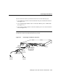
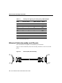
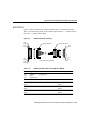
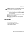
Step 4 If you have a synchronous serial module, use a serial transition cable to connect
the synchronous serial port to a modem or DSU/CSU. (See Figure 3-23.)
Connecting Synchronous Serial Cables
H5369
Figure 3-23
SERIAL
ACTIVITY
SERIAL 0
Serial transition
cable
SERIAL 1
Synchronous serial
port (DB-60)
BRI 0
Router
DSU/CSU or
other DCE
EIA/TIA-232, EIA/TIA-449, V.35,
X.21, or EIA-530 connector
Installing the Cisco 2524 and Cisco 2525 Routers 3-23
Connecting to the Network
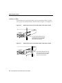
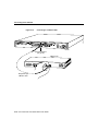
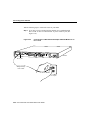
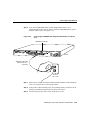
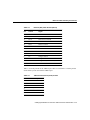
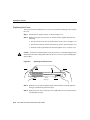
Step 5 If you have an ISDN BRI module (without an integrated NT1 device), use a
straight-through RJ-45-to-RJ-45 cable to connect the ISDN BRI (RJ-45) port to
an NT1 device. (See Figure 3-24.)
Figure 3-24
Connecting the ISDN BRI Module to an NT1 Device
ISDN BRI port (RJ-45)
ISDN-BRI
SERIAL 0
ACTIVITY
SERIAL 1
BRI 0
Router
H5257
Straight-through
RJ-45-to-RJ-45 cable
S/T interface
NT1 device
3-24 Cisco 2524 and Cisco 2525 Router User Guide
Connecting to the Network
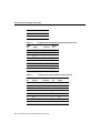
Step 6 If you have an ISDN BRI module with an integrated NT1 device, use a
straight-through RJ-45-to-RJ-45 cable to connect the ISDN BRI (RJ-45) port to
an RJ-45 or RJ-11 jack. (See Figure 3-25.)
Figure 3-25
Connecting the ISDN BRI with Integrated NT1 Module to an RJ-45
Jack
H5258
ISDN BRI port (RJ-45)
ISDN-BRI
with NTI
SERIAL 0
SERIAL 1
ACT NT1
U
BRI 0
Router
Straight-through cable
with RJ-45 or RJ-11
connectors
RJ-45 or
RJ-11 jack
Step 7 If the router is configured with fewer than three WAN modules, install a blank slot
cover over each open slot to ensure proper airflow.
Step 8 Using an M 3.5 thread-forming screw (not included), attach a ground wire to the
protective grounding terminal on the rear panel of the chassis.
Step 9 Connect the power cable to the router and the power source.
Installing the Cisco 2524 and Cisco 2525 Routers 3-25
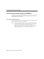
Connecting the Console Terminal and Modem
Connecting the Console Terminal and Modem
You use the console terminal for local administrative access to the router. You can connect
only a terminal to the console port. You can use the auxiliary port with a terminal or a
modem for remote access to the router.
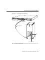
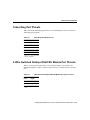
Connecting to the Console Port
Take the following steps to connect a terminal (an ASCII terminal or a PC running terminal
emulation software) to the console port on the router:
Step 1 Connect the terminal using an RJ-45 roll-over cable and an RJ-45-to-DB-25 or
RJ-45-to-DB-9 adapter. The adapters provided by Cisco Systems are labeled
Terminal. Other types of adapters are not included. (See Figure 3-26.)
Additional information on roll-over cable pinouts is provided in the appendix
“Cabling Specifications for the Cisco 2524 and Cisco 2525 Routers.”
3-26 Cisco 2524 and Cisco 2525 Router User Guide
Connecting the Console Terminal and Modem
Figure 3-26
SERIAL 0
Connecting the Console Terminal
SERIAL 1
BRI 0
Router
Console port
connector (RJ-45)
PC
OK
I/O
card
H5366
AUX
SER 0
LAN
ETH
RJ-45 roll-over cable
RJ-45-to-DB-25 adapter
Step 2 Configure your terminal or PC terminal emulation software for 9600 baud, 8 data
bits, no parity, and 2 stop bits.
Installing the Cisco 2524 and Cisco 2525 Routers 3-27
Connecting the Console Terminal and Modem
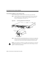
Connecting a Modem to the Auxiliary Port
Take the following steps to connect a modem to the auxiliary port on the router:
Step 1 Connect a modem to the auxiliary port using an RJ-45 roll-over cable with an
RJ-45-to-DB-25 or RJ-45-to-DB-9 adapter. The adapter provided by Cisco
Systems is labeled Modem. (See Figure 3-27.)
Connecting a Modem to the Auxiliary Port
H5270
Figure 3-27
SERIAL 0
SERIAL 1
BRI 0
Router
Auxiliary port
connector (RJ-45)
RJ-45 roll-over
cable
Modem
RJ-45-to-DB-25 adapter
(EIA/TIA-232)
Step 2 Make sure that your modem and the auxiliary port on the router are configured for
the same transmission speed (38400 baud is typical) and hardware flow control
with Data Carrier Detect (DCD) and Data Terminal Ready (DTR) operations.
Warning This equipment is intended to be grounded. Ensure that the host is connected to
earth ground during normal use. (To see translated versions of this warning, refer to the
appendix “Translated Safety Warnings.”)
3-28 Cisco 2524 and Cisco 2525 Router User Guide
What to Do after Installing the Router Hardware
What to Do after Installing the Router Hardware
After you have installed the router, proceed to the chapter “Configuring the Cisco 2524 and
Cisco 2525 Routers” for software configuration information.
Installing the Cisco 2524 and Cisco 2525 Routers 3-29
What to Do after Installing the Router Hardware
3-30 Cisco 2524 and Cisco 2525 Router User Guide
4
CHAPT E R
Configuring the Cisco 2524 and
Cisco 2525 Routers
This chapter describes how to configure the Cisco 2524 and Cisco 2525 routers and
contains the following sections:
•
•
•
•
•
Booting the Router for the First Time
Configuring the Router
Specifying the Boot Method
Checking the Configuration Settings
Getting More Information
This chapter provides just enough information to get the router up and running. For
Cisco IOS Release 11.0 and earlier releases, refer to the Router Products Configuration
Guide for additional configuration information. For Cisco IOS Release 11.1 and later
releases, refer to the Configuration Fundamentals Configuration Guide.
Booting the Router for the First Time
Each time you power on the router, it goes through the following boot sequence:
1 The router goes through power-on self-test diagnostics to verify basic operation of the
CPU, memory, and interfaces.
2 The system bootstrap software (boot image) executes and searches for a valid Cisco IOS
image (router operating system software). The source of the Cisco IOS image (Flash
memory or a Trivial File Transfer Protocol [TFTP] server) is determined by the
configuration register setting. The factory-default setting for the configuration register
is 0x2102, which indicates that the router should attempt to load a Cisco IOS image
from Flash memory.
Configuring the Cisco 2524 and Cisco 2525 Routers 4-1
Configuring the Router
3 If after five attempts a valid Cisco IOS image is not found in Flash memory, the router
reverts to boot ROM mode (which is used to install or upgrade a Cisco IOS image).
4 If a valid Cisco IOS image is found, then the router searches for a valid configuration
file.
5 If a valid configuration file is not found in NVRAM, the router runs the System
Configuration Dialog so you can configure it manually. For normal router operation,
there must be a valid Cisco IOS image in Flash memory and a configuration file in
NVRAM.
The first time you boot your router, you will need to configure the router interfaces and then
save the configuration to a file in NVRAM. Proceed to the next section, “Configuring the
Router,” for configuration instructions.
Configuring the Router
You can configure the router using one of the following procedures:
•
•
Configuration mode—Recommended if you are familiar with Cisco IOS commands.
•
System Configuration Dialog—Recommended if you are not familiar with Cisco IOS
commands.
AutoInstall—Recommended for automatic installation if another router running
Cisco IOS software is installed on the network. This configuration method must be set
up by someone with experience using Cisco IOS software.
Use the procedure that best fits the needs of your network configuration and level of
Cisco IOS experience.
Timesaver Acquire the correct network addresses from your system administrator or
consult your network plan to determine correct addresses before you begin to configure the
router.
4-2 Cisco 2524 and Cisco 2525 Router User Guide
Configuring the Router
Using Configuration Mode
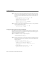
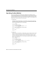
You can configure the router manually if you prefer not to use AutoInstall or the System
Configuration Dialog. Take the following steps to configure the router manually:
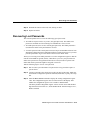
Step 1 Connect a console terminal following the instructions in the section “Connecting
the Console Terminal and Modem” in the chapter “Installing the Cisco 2524 and
Cisco 2525 Routers,” and then power ON the router.
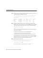
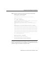
Step 2 When you are prompted to enter the initial dialog, enter no to go into the normal
operating mode of the router:
Would you like to enter the initial dialog? [yes]: no
Step 3 After a few seconds you will see the user EXEC prompt (Router>). Enter the
enable command to enter enable mode. You can only make configuration changes
in enable mode.
Router> enable
The prompt changes to the privileged EXEC (enable) prompt:
Router#
Step 4 Enter the configure terminal command at the enable prompt to enter
configuration mode:
Router# configure terminal
You can now enter any changes you want to the configuration.
Step 5 Press Ctrl-Z to exit configuration mode.
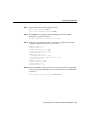
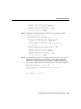
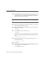
To see the current operating configuration, enter the show running-config command at the
enable prompt:
Router# show running-config
To see the configuration in NVRAM, enter the show startup-config command at the enable
prompt:
Router# show startup-config
Configuring the Cisco 2524 and Cisco 2525 Routers 4-3
Configuring the Router
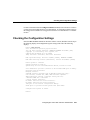
The results of the show running-config and show startup-config commands will be
different if you have made changes to the configuration but have not yet written them to
NVRAM.
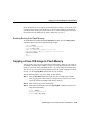
To make your changes permanent, enter the copy running-config startup-config
command at the enable prompt:
Router# copy running-config startup-config
********
The router is now configured and will boot with the configuration you entered.
Using AutoInstall
The AutoInstall process is designed to configure the router automatically after connection
to your WAN. In order for AutoInstall to work properly, a Transmission Control
Protocol/Internet Protocol (TCP/IP) host on your network must be preconfigured to provide
the required configuration files. The TCP/IP host may exist anywhere on the network as
long as the following two conditions are maintained:
1 The host must be on the remote side of the router’s synchronous serial connection to the
WAN.
2 User Datagram Protocol (UDP) broadcasts to and from the router and the TCP/IP host
must be enabled.
This functionality is coordinated by your system administrator at the site where the TCP/IP
host is located. You should not attempt to use AutoInstall unless the required files have been
provided on the TCP/IP host. For Cisco IOS Release 11.0 and earlier releases, refer to the
publication Router Products Configuration Guide for additional information. For
Cisco IOS Release 11.1 and later releases, refer to the publication Configuration
Fundamentals Configuration Guide.
Note AutoInstall works on synchronous serial connections only. The 2-wire
switched 56-kbps DSU/CSU module operates on switched 56-kbps circuits only; therefore,
you cannot use it for AutoInstall.
4-4 Cisco 2524 and Cisco 2525 Router User Guide
Configuring the Router
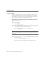
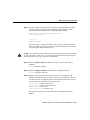
Take the following steps to prepare your router for the AutoInstall process:
Step 1 Attach the WAN cable to the router.
Step 2 Turn ON power to the router.
The router will load the operating system image from Flash memory. If the remote
end of the WAN connection is connected and properly configured, the AutoInstall
process will begin.
If AutoInstall successfully completes, you can write the configuration data to the
router’s NVRAM. Perform the following step to complete this task.
Step 3 Enter the copy running-config startup-config command:
Router# copy running-config startup-config
Taking this step saves the configuration settings that the AutoInstall process
created in the router. If you do not do this, your configuration will be lost the next
time you reload the router.
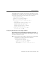
Using the System Configuration Dialog
If you do not plan to use AutoInstall, make sure all the WAN cables are disconnected from
the router. This will prevent the router from attempting to the run the AutoInstall process.
The router will attempt to run AutoInstall whenever you power it on if there is a WAN
connection on both ends and the router does not have a configuration file stored in
NVRAM. It can take several minutes for the router to determine that AutoInstall is not set
up to a remote TCP/IP host.
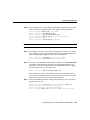
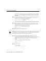
If your router does not have a configuration (setup) file and you are not using AutoInstall,
the router will automatically start the setup command facility. An interactive dialog called
the System Configuration Dialog appears on the console screen. This dialog helps you
navigate through the configuration process by prompting you for the configuration
information necessary for the router to operate.
Many prompts in the System Configuration Dialog include default answers, which are
included in square brackets following the question. To accept a default answer, press
Return; otherwise, enter your response.
This section gives an example configuration using the System Configuration Dialog. When
you are configuring your router, respond as appropriate for your network.
Configuring the Cisco 2524 and Cisco 2525 Routers 4-5
Configuring the Router
At any time during the System Configuration Dialog, you can request help by typing a
question mark (?) at a prompt.
Before proceeding with the System Configuration Dialog, obtain from your system
administrator the node addresses and the number of bits in the subnet field (if applicable)
of the Ethernet and synchronous serial ports. For more information about Internet Protocol
(IP) addresses and subnets, refer to the publication Internetworking Technology Overview.
(See the section “Getting More Information” at the end of this chapter.)
Take the following steps to configure the router using the System Configuration Dialog:
Step 1 Connect a console terminal to the console connector on the rear panel of your
router, and turn ON power to the router. (For more information, refer to the section
“Connecting the Console Terminal and Modem” in the chapter “Installing the
Cisco 2524 and Cisco 2525 Routers.”)
Note The default parameters for the console port are 9600 baud, 8 data bits, no parity, and
2 stop bits.
Step 2 After about 30 seconds, information similar to the following is displayed on the
console screen.
Note The messages displayed vary, depending on the Cisco IOS release and feature set
you selected. The screen displays in this section are for reference only and may not exactly
reflect the screen displays on your console.
When you see this information, you have successfully booted your router:
System Bootstrap, Version X.X(XXXX) [XXXXX XX], RELEASE SOFTWARE
Copyright (c) 1986-1992 by Cisco Systems
2500 processor with 4096 Kbytes of main memory
Notice: NVRAM invalid, possibly due to write erase.
F3: 5797928+162396+258800 at 0x3000060
4-6 Cisco 2524 and Cisco 2525 Router User Guide
Configuring the Router
Restricted Rights Legend
Use, duplication, or disclosure by the Government is
subject to restrictions as set forth in subparagraph
(c) of the Commercial Computer Software - Restricted
Rights clause at FAR sec. 52.227-19 and subparagraph
(c) (1) (ii) of the Rights in Technical Data and Computer
Software clause at DFARS sec. 252.227-7013.
Cisco Systems, Inc.
170 West Tasman Drive
San Jose, California 95134-1706
Cisco Internetwork Operating System Software
IOS (tm) X000 Software (IGS-J-L), Version XX.X(XXXX) [XXXXX XXX]
Copyright (c) 1986-1996 by Cisco Systems, Inc.
Compiled Fri 20-Oct-95 16:02 by XXXXX
Image text-base: 0x03030FC0, data-base: 0x00001000
Cisco 252X (68030) processor (revision A) with 4092K/2048K bytes of
memory.
Processor board ID 00000000
Bridging software.
SuperLAT software copyright 1990 by Meridian Technology Corp).
X.25 software, Version X.X, NET2, BFE and GOSIP compliant.
TN3270 Emulation software (copyright 1994 by TGV Inc).
Basic Rate ISDN software, Version X.X.
1 Ethernet/IEEE 802.3 interface.
2 Serial network interfaces.
1 ISDN Basic Rate interface.
32K bytes of non-volatile configuration memory.
8192K bytes of processor board System flash (Read ONLY)
Notice: NVRAM invalid, possibly due to write erase.
--- System Configuration Dialog --At any point you may enter a question mark '?' for help.
Refer to the 'Getting Started' Guide for additional help.
Use ctrl-c to abort configuration dialog at any prompt.
Default settings are in square brackets '[]'.
Would you like to enter the initial configuration dialog? [yes]:
Step 3 Press Return or enter yes to begin the configuration process.
Configuring the Cisco 2524 and Cisco 2525 Routers 4-7
Configuring the Router
Step 4 When the System Configuration Dialog asks whether you want to view the current
interface summary, press Return or enter yes:
First, would you like to see the current interface summary? [yes]:
Any interface listed with OK? value "NO" does not have a valid
configuration
Interface
Ethernet0
BRI0
Serial0
Serial1
IP-Address
unassigned
unassigned
unassigned
unassigned
OK?
NO
NO
NO
NO
Method
not set
not set
not set
not set
Status
up
up
down
down
Protocol
down
up
down
down
Step 5 Configure the global parameters. Choose which protocols to support on the
Ethernet interface. For IP installations, you can press Return to accept the default
values (in brackets) for most of the questions. A typical configuration follows:
Configuring global parameters:
Enter host name [Router]:
Next, you are prompted to enter an enable secret password. There are two types of
privileged-level passwords:
•
•
Enable secret password (a very secure, encrypted password)
Enable password (a less secure, nonencrypted password)
The enable password is used when the enable secret password does not exist.
For maximum security, be sure the passwords are different. If you enter the same
password for both, the router will accept your entry, but will display a warning
message indicating that you should enter a different password.
Step 6 Enter an enable secret password:
The enable secret is a one-way cryptographic secret used
instead of the enable password when it exists.
Enter enable secret: pail
The enable password is used when there is no enable secret
and when using older software and some boot images.
4-8 Cisco 2524 and Cisco 2525 Router User Guide
Configuring the Router
Step 7 Enter the enable and virtual terminal passwords:
Enter enable password: shovel
Enter virtual terminal password: vterm1
Step 8 Press Return to accept Simple Network Management Protocol (SNMP)
management, or enter no to refuse it:
Configure SNMP Network Management? [yes]: no
Step 9 In the following example, the router is configured for AppleTalk, IP, and IPX.
Configure the appropriate protocols for your router:
Configure Vines? [no]:
Configure LAT? [no]:
Configure AppleTalk? [no]: yes
Multizone networks? [no]: yes
Configure DECnet? [no]:
Configure IP? [yes]:
Configure IGRP routing? [yes]:
Your IGRP autonomous system number [1]: 15
Configure CLNS? [no]:
Configure bridging? [no]:
Configure IPX? [no]: yes
Configure XNS? [no]:
Configure Apollo? [no]:
Step 10 Enter the ISDN BRI switch type for the router. The ISDN switch type appropriate
for the router depends on the ISDN provider’s equipment. Table 4-1 lists the ISDN
switch types.
Enter ISDN BRI Switch Type [none]: basic-5ess
Configuring the Cisco 2524 and Cisco 2525 Routers 4-9
Configuring the Router
Table 4-1
ISDN Switch Types
Country
ISDN Switch Type
Description
Australia
basic-ts013
Australian TS013 switches
Europe
basic-1tr6
German 1TR6 ISDN switches
basic-nwnet3
Norwegian NET3 ISDN switches (phase 1)
basic-net3
NET3 ISDN switches (UK and others)
vn2
French VN2 ISDN switches
vn3
French VN3 ISDN switches
Japan
ntt
Japanese NTT ISDN switches
North America
basic-5ess
AT&T basic rate switches
basic-dms100
NT DMS-100 basic rate switches
basic-ni1
National ISDN-1 switches
basic-nznet3
New Zealand NET3 switches
New Zealand
Configuring the ISDN BRI Interface
This section explains how to configure the ISDN BRI interface. If an ISDN BRI WAN
module is not installed in your router, skip this section and proceed with the next section,
“Configuring the Ethernet or Token Ring Interfaces.”
4-10 Cisco 2524 and Cisco 2525 Router User Guide
Configuring the Router
The ISDN BRI interface is configured to allow connection to ISDN WANs. To configure
the ISDN BRI interface, respond as follows (using your addresses and subnet mask) to the
setup prompts, substituting the correct addresses and host names as appropriate:
Configuring interface BRI0:
Is this interface in use? [yes]
Configure IP on this interface? [yes]
IP address for this interface: 172.16.71.1
Number of bits in subnet field [0]: 8
lass B network is 172.16.0.0, 8 subnet bits; mask is
255.255.255.0
Configure AppleTalk on this interface? [no]: yes
Extended AppleTalk network? [no]: yes
AppleTalk starting cable range [0]: 1
AppleTalk ending cable range [1]: 2
AppleTalk zone name [myzone]:
AppleTalk additional zone name: otherzone
AppleTalk additional zone name:
Configure IPX on this interface? [no]: yes
IPX network number [1]: B000
Configuring the Ethernet or Token Ring Interfaces
Take the following steps to configure the Ethernet or Token Ring interface to allow
communication over a LAN. To configure the interface parameters, you need to know your
Ethernet or Token Ring interface network addresses. In this example, the system is being
configured for an Ethernet LAN using IP.
Step 1 Respond as follows (using your addresses and subnet mask) to the setup prompts,
substituting the correct addresses and host names as appropriate:
Configuring interface Ethernet0:
Is this interface in use? [yes]:
Configure IP on this interface? [yes]:
IP address for this interface: 172.16.72.1
Number of bits in subnet field [8]: 8
Class B network is 172.16.0.0, 8 subnet bits; mask is
255.255.255.0
Configuring the Cisco 2524 and Cisco 2525 Routers 4-11
Configuring the Router
Step 2 Enter yes if you will be using AppleTalk on the interface. Enter yes to configure
the router for extended AppleTalk networks, and then enter the cable range. Enter
the zone name, and any other additional zones that will be associated with your
local zone:
Configure AppleTalk on this interface? [no]: yes
Extended AppleTalk network? [no]: yes
AppleTalk starting cable range [0]: 3
AppleTalk ending cable range [1]: 3
AppleTalk zone name [myzone]:
AppleTalk additional zone name: otherzone
AppleTalk additional zone name:
Step 3 Determine if you are going to enable IPX on the interface. If so, enter yes and then
enter the unique IPX network number:
Configure IPX on this interface? [no]: yes
IPX network number [1]: B001
Configuring the Synchronous Serial Interfaces
The synchronous serial interfaces are configured to allow connection to WANs. Once the
Ethernet or Token Ting port on your router has been configured, take the following steps to
configure the synchronous serial interfaces:
Step 1 Press Return or enter yes to configure serial port 0:
Configuring interface Serial0:
Is this interface in use? [yes]:
Step 2 Determine which protocols you want on the synchronous serial interface and enter
the appropriate responses. In this example, the system is being configured for IP,
AppleTalk, and IPX:
Configure IP on this interface? [yes]:
Configure IP unnumbered on this interface? [no]:
IP address for this interface: 172.16.73.1
Number of bits in subnet field [8]:
Class B network is 172.16.0.0, 8 subnet bits; mask is
255.255.255.0
Configure AppleTalk on this interface? [no]: yes
Extended AppleTalk network? [yes]:
AppleTalk starting cable range [2]: 4
4-12 Cisco 2524 and Cisco 2525 Router User Guide
Configuring the Router
AppleTalk ending cable range [3]: 4
AppleTalk zone name [myzone]: ZZ Serial
AppleTalk additional zone name:
Configure IPX on this interface? [no]: yes
IPX network number [2]: B002
Step 3 Configure the second synchronous serial interface, for example, as follows:
Configuring interface Serial1:
Is this interface in use? [yes]:
Configure IP on this interface? [yes]:
Configure IP unnumbered on this interface? [no]:
IP address for this interface: 172.16.74.2
Number of bits in subnet field [8]:
Class B network is 172.16.0.0, 8 subnet bits; mask is
255.255.255.0
Configure AppleTalk on this interface? [no]: yes
AppleTalk starting cable range [3]: 5
AppleTalk ending cable range [4]: 5
AppleTalk zone name [myzone]: ZZ Serial
AppleTalk additional zone name:
Configure IPX on this interface? [no]: yes
IPX network number [3]: B003
Step 4 The configuration you enter is now displayed and you are asked if you want to use
the displayed configuration. If you enter no, you will lose the configuration
information you just entered and you can begin the configuration again. If you
enter yes, the configuration will be entered and saved in the startup configuration:
Use this configuration? [yes/no]: yes
Building configuration...
Use the enabled mode 'configure' command to modify this
configuration.
Press RETURN to get started!
Configuring the Cisco 2524 and Cisco 2525 Routers 4-13
Configuring the Router
Configuring ISDN
If you have an ISDN BRI WAN module, configure the BRI port for ISDN. This section
explains typical ISDN configurations for one or two B channels. In the examples that
follow, the BRI port is configured for IP routing, Challenge Handshake Authentication
Protocol (CHAP), and Point-to-Point Protocol (PPP) encapsulation.
Take the following steps to configure the router for a basic ISDN PPP connection on a
single B channel or two B channels, substituting the correct addresses and host names as
appropriate for your network:
Step 1 Enter enable mode:
Router> enable
password: enablepassword
Step 2 Enter the configure terminal command. Then enter the host name and password
that the router will use for CHAP caller identification:
Router# config term
Router (config)# username targetrouter password abc
Note The username and password must match the username and password already set on
the router to which the ISDN connection will be made. The username and password are
case sensitive.
Step 3 If you have not already done so, enter the isdn switch-type command to configure
the ISDN switch type:
router (config)# isdn switch-type switch-type
Refer to Table 4-1 earlier in this chapter for a list of ISDN switch types.
4-14 Cisco 2524 and Cisco 2525 Router User Guide
Configuring the Router
Step 4 Enter the BRI interface, encapsulation method (PPP), authentication type, target
router’s IP address and ISDN number to dial, and the dialer group number:
Router (config)# interface bri port_number
Router (config-if)# encapsulation ppp
Router (config-if)# ppp authentication chap
Router (config-if)# dialer map ip targetrouter_ipaddress
targetrouter_phonenumber
Router (config-if)# dialer-group groupnumber
Note Do not use periods or hyphens when you enter dialing numbers.
Step 5 Some ISDN switch types, such as Basic NI1 or DMS-100 switch service, require
you to configure a service profile identifier (SPID). Enter the SPID information as
follows, substituting the appropriate entries for your installation:
Router (config-if)# isdn spid1 SPID_no phone_number
Router (config-if)# isdn spid2 SPID_no phone_number
Step 6 To set up a second B channel for bandwidth on demand, enter the load-threshold
command to set the ISDN load threshold. The load threshold determines the
percentage of network loading at which the second ISDN B channel is triggered.
The value ranges from 1 to 255 (100 percent).
Router (config-if)# dialer load-threshold 128
In this example, the value of 128 means that when the first B channel reaches
50 percent of its bandwidth capacity (128 equals 50 percent of 255), the second B
channel will be activated to assist with the bandwidth load.
Step 7 Enter the access-list command to configure the ISDN line to come up whenever
IP packets are to be sent:
Router (config-if)# access-list access-list-number permit ip
sourcerouter-ipnetwork sourcerouter-subnetmask
targetrouter-ipnetwork targetrouter-subnetmask
Router (config)# dialer-list groupnumber list access-list-number
Configuring the Cisco 2524 and Cisco 2525 Routers 4-15
Configuring the Router
Step 8 Configure a static route to allow connectivity to the target router’s local network.
Enter the network number of the target router’s local IP network and subnet mask,
and the IP address of the target router’s BRI port.
Router (config)# ip route targetrouter_ipnetwork subnetmask
targetBRIport_ipaddress
Step 9 Enter the exit command to exit configuration mode.
Step 10 Enter the copy running-config startup-config command to save the
configuration to NVRAM.
Configuring Switched 56
This section explains how to configure the 2-wire switched 56-kbps and 4-wire 56/64-kbps
DSU/CSU WAN modules for switched 56-kbps circuit-switched service.
You can configure the 2-wire switched 56-kbps DSU/CSU WAN module for
switched 56-kbps service, but not Digital Data System ([DDS], which are leased or
dedicated lines). The 4-wire 56/64-kbps DSU/CSU WAN module is configured for DDS as
the factory default, but it can be configured for either switched 56/64-kbps service or DDS.
(See the next section, “Configuring DDS.”)
For Cisco IOS Release 11.0 and earlier releases, refer to the Router Products Command
Reference for more information about the commands in this section. For Cisco IOS
Release 11.1 and later releases, refer to the Configuration Fundamentals Command
Reference.
Take the following steps to configure the 2-wire switched 56-kbps and 4-wire 56/64-kbps
DSU/CSU WAN module for circuit-switched service, substituting the correct addresses and
host names as appropriate for your network:
Step 1 Enter enable mode:
Router> enable
password: enablepassword
Step 2 Enter configuration mode:
Router# config term
Router(config)#
4-16 Cisco 2524 and Cisco 2525 Router User Guide
Configuring the Router
Step 3 Assign an IP address to the serial port on the module:
Router(config)# interface serial port_number
Router(config-if)# ip address ipaddress subnetmask
Router(config-if)# no keepalive
Step 4 If you have a 2-wire switched 56-kbps WAN module, skip this step and proceed
to Step 5. If you have a 4-wire 56/64-kbps DSU/CSU WAN module, set the
network type to switched as follows:
Router(config-if)# service-module 56k network-type switched
Step 5 Set the carrier type, where carrier can be att, sprint, or other:
Router(config-if)# service-module 56k switched-carrier carrier
Step 6 Enter the dialer information:
Router(config-if)# dialer in-band
Router(config-if)# dialer string targetrouter_phonenumber
Router(config-if)# dialer-group groupnumber
Router(config-if)# exit
Router(config)# dialer-list groupnumber protocol protocol permit
Router(config)#
Step 7 Return to user EXEC mode:
Router(config)# exit
Router# exit
Router>
Configuring DDS
The 4-wire 56/64-kbps DSU/CSU WAN module is configured for DDS (which are leased
or dedicated lines) as the factory default, but it can be configured for either
switched 56/64-kbps service or DDS. The DDS configuration is described in this section.
To configure the 4-wire 56/64-kbps DSU/CSU WAN module for circuit-switched service,
follow the instructions in the previous section, “Configuring Switched 56.”
For Cisco IOS Release 11.0 and earlier releases, refer to the Router Products Command
Reference for more information about the commands in this section. For Cisco IOS
Release 11.1 and later releases, refer to the Configuration Fundamentals Command
Reference.
Configuring the Cisco 2524 and Cisco 2525 Routers 4-17
Configuring the Router
Take the following steps to configure the 4-wire 56/64-kbps DSU/CSU WAN module for
DDS, substituting the correct addresses and host names as appropriate for your network:
Step 1 Enter enable mode:
Router> enable
password: enablepassword
Step 2 Enter configuration mode:
Router# config term
Router(config)#
Step 3 Assign an IP address to the serial port on the module:
Router(config)# interface serial port_number
Router(config-if)# ip address ipaddress subnetmask
Router(config-if)# no keepalive
Step 4 Set the network type to DDS:
Router(config-if)# service-module 56k network-type dds
Step 5 Return to user EXEC mode:
Router(config-if)# exit
Router(config)# exit
Router# exit
Router>
Configuring the Fractional T1/T1 DSU/CSU WAN Module
This section describes how to configure the fractional T1/T1 DSU/CSU WAN module. This
module is configured for Extended Superframe Format (ESF) signal format, bipolar eight
zero substitution (B8ZS), and full bandwidth as the factory default. Depending on your
networking environment, you might need to change these settings.
For Cisco IOS Release 11.0 and earlier releases, refer to the Router Products Command
Reference for more information about the commands in this section. For Cisco IOS
Release 11.1 and later releases, refer to the Configuration Fundamentals Command
Reference.
4-18 Cisco 2524 and Cisco 2525 Router User Guide
Configuring the Router
Take the following steps to configure the fractional T1/T1 DSU/CSU WAN module for a
typical leased-line connection, substituting the correct addresses and host names as
appropriate for your network:
Step 1 Enter enable mode:
Router> enable
password: enablepassword
Step 2 Enter configuration mode:
Router# config term
Router(config)#
Step 3 Assign an IP address to the serial port on the module:
Router(config)# interface serial port_number
Router(config-if)# ip address ipaddress subnetmask
Router(config-if)# no keepalive
Step 4 Enter the framing type and line code type, substituting framing_type with sf
(Superframe) or esf (Extended Superframe) and linecode_type with ami (alternate
mark inversion) or b8zs (bipolar eight zero substitution):
Router(config-if)# service-module t1 framing framing_type
Router(config-if)# service-module t1 linecode linecode_type
Step 5 If you are using fractional T1 service, enter the time slot range and speed. In the
following example, the time slot range is from 1 to 20 and the speed is 64-kbps:
Router(config-if)# service-module t1 timeslots 1-20 speed 64
Step 6 Return to user EXEC mode:
Router(config-if)# exit
Router(config)# exit
Router# exit
Router>
Configuring the Cisco 2524 and Cisco 2525 Routers 4-19
Specifying the Boot Method
Specifying the Boot Method
You can enter multiple boot commands in the configuration in NVRAM to provide a
backup method for loading the Cisco IOS image onto the router. The router boots using the
first boot command that succeeds. If you enter multiple boot commands, the router executes
them in the order they are entered. There are two ways to load the Cisco IOS image: from
Flash memory or from a TFTP server on the network.
1 Flash memory
Information stored in Flash memory is not vulnerable to network failures that might
occur when you load system software from servers. In the following example, replace
filename with the filename of the Cisco IOS image:
Router> enable
Password: enablepassword
Router# configure terminal
Router (config)# boot system flash filename
Router (config)# Ctrl-Z
Router# copy running-config startup-config
Building configuration ...
[OK]
Router# exit
Router>
2 TFTP server
If Flash memory is not available, or if Flash memory does not contain a valid Cisco IOS
image, you can specify that system software be loaded from a TFTP server on your
network as a backup boot method for the router. In the following example, replace
filename with the filename of the Cisco IOS image, and replace ipaddress with the IP
address of the TFTP server:
Router> enable
Password: enablepassword
Router# configure terminal
Router (config)# boot system tftp filename ipaddress
Router (config)# Ctrl-Z
Router# copy running-config startup-config
Building configuration ...
[OK]
Router# exit
Router>
4-20 Cisco 2524 and Cisco 2525 Router User Guide
Checking the Configuration Settings
For more information about the configure terminal command, refer to the Router Products
Configuration Guide publication for Cisco IOS Release 11.0 and earlier releases. Refer to
the Configuration Fundamentals Configuration Guide for Cisco IOS Release 11.1 and later
releases.
Checking the Configuration Settings
Enter the show version command to check the software version (third line from the top in
the following display) and configuration register setting (at the end of the following
display):
Router> show version
Cisco Internetwork Operating System Software
IOS (tm) XX00 Software (XXX-X-X), RELEASE SOFTWARE XX.X(XXXX) [XXX]
Copyright (c) 1986-1996 by Cisco Systems, Inc.
Compiled Tue XX-XXX-XX 13:07 by XXXXX
Image text-base: 0x03032810, data-base: 0x00001000
ROM: System Bootstrap, Version X.X(XXXX) [XXXXX], RELEASE SOFTWARE
ROM: XX00 Bootstrap Software (XXX-BOOT-X), Version XX.X(XXXXX) [XXXXX]
Router uptime is 4 minutes
System restarted by power-on
System image file is "flash:XXX/XXX-X-X.Nov14", booted via flash
Cisco XXXX(68030) processor (revision X) with 4092K/2048K bytes of memory.
Processor board ID 00000000
Bridging software.
SuperLAT software copyright 199X by Meridian Technology Corp).
X.25 software, Version X.X, NET2, BFE and GOSIP compliant.
TN3270 Emulation software (copyright 199X by TGV Inc).
1 Ethernet/IEEE 802.3 interface.
2 Serial network interfaces.
No module installed for Serial Interface 0
No module installed for Serial Interface 1
32K bytes of non-volatile configuration memory.
8192K bytes of processor board System flash (Read ONLY)
Configuration register is 0x2102
Router>
Configuring the Cisco 2524 and Cisco 2525 Routers 4-21
Getting More Information
Getting More Information
For more information about router software configuration, refer to the following
publications for Cisco IOS Release 11.0 and earlier:
•
•
•
•
•
•
Internetworking Technology Overview
Router Products Configuration Guide
Router Products Command Reference
Configuration Builder Getting Started Guide
CiscoWorks for Windows Getting Started Guide
Troubleshooting Internetworking Systems (as needed)
For Cisco IOS Release 11.1 and later, refer to the following publications:
•
•
•
•
•
•
•
•
•
•
•
Internetworking Technology Overview
Configuration Fundamentals Configuration Guide
Configuration Fundamentals Command Reference
Remote Node and Terminal Services Configuration Guide
Remote Node and Terminal Services Command Reference
Wide-Area Networking Configuration Guide
Wide-Area Networking Command Reference
Standard Network Protocols Configuration Guide
Standard Network Protocols Command Reference
Network Protocols Configuration Guide
Network Protocols Command Reference
These publications are available on UniverCD, Cisco’s online library of product
information. To order UniverCD, or paper documentation, refer to the Cisco Information
Packet publication that accompanied your router.
4-22 Cisco 2524 and Cisco 2525 Router User Guide
C
APPEND IX
Cabling Specifications for the
Cisco 2524 and Cisco 2525
Routers
This appendix provides the following pinout information:
•
•
•
•
•
•
•
•
Console and Auxiliary Port Signals and Pinouts
Ethernet Cable Assembly and Pinouts
Token Ring Port Pinouts
2-Wire Switched 56-kbps DSU/CSU Module Port Pinouts
4-Wire 56/64-kbps DSU/CSU Module Port Pinouts
Fractional T1/T1 DSU/CSU Module Port Pinouts
Synchronous Serial Cable Assemblies and Pinouts
ISDN BRI Port and Cable Pinouts
Note All pins not listed in the tables in this appendix are not connected.
Cabling Specifications for the Cisco 2524 and Cisco 2525 Routers C-1
Console and Auxiliary Port Signals and Pinouts
Console and Auxiliary Port Signals and Pinouts
Your router comes with a console and auxiliary cable kit, which contains the cable and
adapters you need to connect a console (an ASCII terminal or PC running terminal
emulation software) or modem to your router. The console and auxiliary cable kit includes
the following items:
•
RJ-45-to-RJ-45 roll-over cable. (See the next section, “Identifying a Roll-Over Cable,”
for more information.)
•
•
•
RJ-45-to-DB-9 female DTE adapter (labeled Terminal).
RJ-45-to-DB-25 female DTE adapter (labeled Terminal).
RJ-45-to-DB-25 male DCE adapter (labeled Modem).
For console connections, proceed to the section “Console Port Signals and Pinouts” later in
this appendix; for modem connections, proceed to the section “Auxiliary Port Signals and
Pinouts” later in this appendix.
Identifying a Roll-Over Cable
You can identify a roll-over cable by comparing the two modular ends of the cable. Holding
the cables side-by-side, with the tab at the back, the wire connected to the pin on the outside
of the left plug should be the same color as the wire connected to the pin on the outside of
the right plug. (See Figure C-1.) If your cable was purchased from Cisco Systems, pin 1
will be white on one connector, and pin 8 will be white on the other (a roll-over cable
reverses pins 1 and 8, 2 and 7, 3 and 6, and 4 and 5).
C-2 Cisco 2524 and Cisco 2525 Router User Guide
Console and Auxiliary Port Signals and Pinouts
Figure C-1
Identifying a Roll-Over Cable
Pin 1 and pin 8
should be the
same color
Pin 1
H3824
Pin 8
Console Port Signals and Pinouts
Use the RJ-45-to-RJ-45 roll-over cable and RJ-45-to-DB-9 female DTE adapter (labeled
Terminal) to connect the console port to a PC running terminal emulation software.
Figure C-2 shows how to connect the console port to a PC. Table C-1 lists the pinouts for
the asynchronous serial console port, the RJ-45-to-RJ-45 roll-over cable, and the
RJ-45-to-DB-9 female DTE adapter (labeled Terminal).
Figure C-2
Connecting the Console Port to a PC
RJ-45-to-RJ-45
rollover cable
PC
RJ-45-to-DB-9 adapter
(labeled Terminal)
H6093
Router
Cabling Specifications for the Cisco 2524 and Cisco 2525 Routers C-3
Console and Auxiliary Port Signals and Pinouts
Table C-1
Console Port Signaling and Cabling Using a DB-9 Adapter
Console
Port (DTE)
RJ-45-to-RJ-45
Roll-Over Cable
RJ-45-to-DB-9
Terminal
Adapter
Console
Device
Signal
RJ-45 Pin
RJ-45 Pin
DB-9 Pin
Signal
1
RTS
1
8
8
CTS
DTR
2
7
6
DSR
TxD
3
6
2
RxD
GND
4
5
5
GND
GND
5
4
5
GND
RxD
6
3
3
TxD
DSR
7
3
4
DTR
1
7
RTS
CTS
1
8
1. Pin 1 is connected internally to Pin 8.
Use the RJ-45-to-RJ-45 roll-over cable and RJ-45-to-DB-25 female DTE adapter (labeled
Terminal) to connect the console port to a terminal. Figure C-3 shows how to connect the
console port to a terminal. Table C-2 lists the pinouts for the asynchronous serial console
port, the RJ-45-to-RJ-45 roll-over cable, and the RJ-45-to-DB-25 female DTE adapter
(labeled Terminal).
Figure C-3
Connecting a the Console Port to a Terminal
RJ-45-to-RJ-45
rollover cable
Terminal
RJ-45-to-DB-25 adapter
(labeled Terminal)
C-4 Cisco 2524 and Cisco 2525 Router User Guide
H6092
Router
Console and Auxiliary Port Signals and Pinouts
Table C-2
Console Port Signaling and Cabling Using a DB-25 Adapter
Console
Port (DTE)1
RJ-45-to-RJ-45
Roll-Over Cable
RJ-45-to-DB-25
Terminal
Adapter
Console
Device
Signal
RJ-45 Pin
RJ-45 Pin
DB-25 Pin
Signal
2
RTS
1
8
5
CTS
DTR
2
7
6
DSR
TxD
3
6
3
RxD
GND
4
5
7
GND
GND
5
4
7
GND
RxD
6
3
2
TxD
DSR
7
3
20
DTR
1
4
RTS
CTS
1
8
1. You can use the same cabling to connect a console to the auxiliary port.
2. Pin 1 is connected internally to Pin 8.
Auxiliary Port Signals and Pinouts
Use the RJ-45-to-RJ-45 roll-over cable and RJ-45-to-DB-25 male DCE adapter (labeled
Modem) to connect the auxiliary port to a modem. Figure C-4 shows how to connect the
auxiliary port to a modem. Table C-3 lists the pinouts for the asynchronous serial auxiliary
port, the RJ-45-to-RJ-45 roll-over cable, and the RJ-45-to-DB-25 male DCE adapter
(labeled Modem).
Figure C-4
Connecting the Auxiliary Port to a Modem
RJ-45-to-RJ-45
rollover cable
Modem
RJ-45-to-DB-25 adapter
(labeled Modem)
H6094
Router
Cabling Specifications for the Cisco 2524 and Cisco 2525 Routers C-5
Ethernet Cable Assembly and Pinouts
Table C-3
Auxiliary Port Signaling and Cabling Using a DB-25 Adapter
AUX Port
(DTE)
RJ-45-to-RJ-45
Roll-Over Cable
RJ-45-to-DB-25
Modem Adapter
Modem
Signal
RJ-45 Pin
RJ-45 Pin
DB-25 Pin
Signal
1
RTS
1
8
4
RTS
DTR
2
7
20
DTR
TxD
3
6
3
TxD
GND
4
5
7
GND
GND
5
4
7
GND
RxD
6
3
2
RxD
DSR
7
3
8
DCD
1
5
CTS
CTS
1
8
1. Pin 1 is connected internally to Pin 8.
Ethernet Cable Assembly and Pinouts
This section describes the pinouts for the Ethernet ports and cables.
Figure C-5 shows an Ethernet (AUI) cable assembly, and Table C-4 lists an AUI cable
pinout.
Figure C-5
Ethernet (AUI) Cable Assembly
J1-1
J1-9
J1
-15
J1-8
C-6 Cisco 2524 and Cisco 2525 Router User Guide
J2
H1031a
J2-1
J2-9
J2-15
J2-8
Ethernet Cable Assembly and Pinouts
Table C-4
Ethernet (AUI) Cable Pinouts (DB-15)
Pin
Ethernet
Circuit
Signal
3
DO-A
Data Out Circuit A
10
DO-B
Data Out Circuit B
11
DO-S
Data Out Circuit Shield
5
DI-A
Data In Circuit A
12
DI-B
Data In Circuit B
4
DI-S
Data In Circuit Shield
2
CI-A
Control In Circuit A
9
CI-B
Control In Circuit B
1
CI-S
Control In Circuit Shield
6
VC
Voltage Common
13
VP
Voltage Plus
14
VS
Voltage Shield (L25 and M25)
Shell
PG
Protective Ground
Table C-5 lists the pinouts for the 10BaseT port. Table C-6 and Table C-7 list the pinouts
for the cables you can use with the 10BaseT port.
Table C-5
10BaseT Ethernet Port (RJ-45) Pinouts
Pin
Description
1
TX+
2
TX–
3
RX+
4
–
5
–
6
RX–
Cabling Specifications for the Cisco 2524 and Cisco 2525 Routers C-7
Ethernet Cable Assembly and Pinouts
Pin
Description
7
–
8
–
Table C-6
RJ-45-to-RJ-45 Straight-Through Ethernet Cable Pinouts
RJ-45
Pin
Signal
Direction
RJ-45
Pin
1
TX+
–>
1
2
TX–
–>
2
3
RX+
<–
3
4
–
–
4
5
–
–
5
6
RX–
<–
6
7
–
–
7
8
–
–
8
Table C-7
RJ-45-to-RJ-45 Crossover Ethernet Cable Pinouts
RJ-45
Pin
Signal
Direction
RJ-45
Pin
Signal
1
TX+
–>
3
RX+
2
TX–
–>
6
RX–
3
RX+
<–
1
TX+
4
–
–
4
–
5
–
–
5
–
6
RX–
<–
2
TX–
7
–
–
7
–
8
–
–
8
–
C-8 Cisco 2524 and Cisco 2525 Router User Guide
Token Ring Port Pinouts
Token Ring Port Pinouts
Table C-8 lists the Token Ring port pinouts. Use a Token Ring lobe cable to connect the
Token Ring port to a MAU.
Table C-8
Token Ring Port (DB-9) Pinouts
9 Pin1
Signal
1
Receive
3
+5V2
5
Transmit
6
Receive
9
Transmit
1. Pins 2, 4, 7, and 8 are ground.
2. 600 mA maximum.
2-Wire Switched 56-kbps DSU/CSU Module Port Pinouts
Table C-9 lists the port pinouts for the 2-wire switched 56 DSU/CSU module. Use a
straight-through RJ-11-to-RJ-11 cable to connect the 2-wire switched 56 port to an RJ-11
jack.
Table C-9
2-Wire Switched 56-kbps DSU/CSU Module Port (RJ-11) Pinouts
RJ-11
6 Pin1
Signal
3
Tip
4
Ring
1. Pins 1, 2, 5, and 6 are not
used.
Cabling Specifications for the Cisco 2524 and Cisco 2525 Routers C-9
4-Wire 56/64-kbps DSU/CSU Module Port Pinouts
4-Wire 56/64-kbps DSU/CSU Module Port Pinouts
Table C-10 lists the port pinouts for the 4-wire 56/64-kbps DSU/CSU module. Use a
straight-through RJ-48S-to-RJ-48S cable to connect the RJ-48S port to an RJ-48S jack.
Table C-10
4-Wire 56/64-kbps DSU/CSU Module Port (RJ-48S) Pinouts
RJ-48S
8 Pin1
Signal
1
Receive ring
2
Receive tip
7
Ring
8
Tip
1. Pins 3, 4, 5, and 6 are not used.
Fractional T1/T1 DSU/CSU Module Port Pinouts
Table C-11 lists the fractional T1/T1 DSU/CSU module port pinouts. Use a
straight-through RJ-48C-to-RJ-48C cable to connect the fractional T1/T1 port to an
RJ-48C jack.
Table C-11
Fractional T1/T1 DSU/CSU Module Port (RJ-48C) Pinouts
RJ-48C
8 Pin1
Description
1
Receive ring
2
Receive tip
4
Ring
5
Tip
1. Pins 3, 6, 7, and 8 are not used.
C-10 Cisco 2524 and Cisco 2525 Router User Guide
Synchronous Serial Cable Assemblies and Pinouts
Synchronous Serial Cable Assemblies and Pinouts
The illustrations and tables in this section provide assembly drawings and pinouts for the
EIA-530 DCE, EIA/TIA-232, EIA/TIA-449, V.35, and X.21 DTE and DCE cables, which
are used with the five-in-one synchronous serial WAN module.
EIA-530
Figure C-6 shows the EIA-530 serial cable assembly, and Table C-12 lists the pinouts.
Arrows indicate signal direction: —> indicates DTE to DCE, and <— indicates DCE to
DTE.
Figure C-6
EIA-530 Serial Cable Assembly
J1-46
J1-45
J1-16
J1-15
60-pin connector
25-pin connector
H1972
J2-13
J2-25
J2-14
J2-1
J1-1
J1-30
J1-31
J1-60
Connectors are not to scale
Table C-12
EIA-530 DTE Cable Pinouts (DB-60 to DB-25)
60 Pin
Signal
25 Pin
Signal
Direction
DTE DCE1
J1-11
J1-12
TxD/RxD+
TxD/RxD–
J2-2
J2-14
BA(A), TxD+
BA(B), TxD–
—>
—>
J1-28
J1-27
RxD/TxD+
RxD/TxD–
J2-3
J2-16
BB(A), RxD+
BB(B), RxD–
<—
<—
Cabling Specifications for the Cisco 2524 and Cisco 2525 Routers C-11
Synchronous Serial Cable Assemblies and Pinouts
60 Pin
Signal
25 Pin
Signal
Direction
DTE DCE1
J1-9
J1-10
RTS/CTS+
RTS/CTS–
J2-4
J2-19
CA(A), RTS+
CA(B), RTS–
—>
—>
J1-1
J1-2
CTS/RTS+
CTS/RTS–
J2-5
J2-13
CB(A), CTS+
CB(B), CTS–
<—
<—
J1-3
J1-4
DSR/DTR+
DSR/DTR–
J2-6
J2-22
CC(A), DSR+
CC(B), DSR–
<—
<—
J1-46
J1-47
Shield_GND
MODE_2
J2-1
–
Shield
–
Shorted
J1-48
J1-49
GND
MODE_1
–
–
–
–
Shorted
J1-5
J1-6
DCD/DCD+
DCD/DCD–
J2-8
J2-10
CF(A), DCD+
CF(B), DCD–
<—
<—
J1-24
J1-23
TxC/RxC+
TxC/RxC–
J2-15
J2-12
DB(A), TxC+
DB(B), TxC–
<—
<—
J1-26
J1-25
RxC/TxCE+
RxC/TxCE–
J2-17
J2-9
DD(A), RxC+
DD(B), RxC–
<—
<—
J1-44
J1-45
LL/DCD
Circuit_GN
D
J2-18
J2-7
LL
Circuit_ GND
—>
–
J1-7
J1-8
DTR/DSR+
DTR/DSR–
J2-20
J2-23
CD(A), DTR+
CD(B), DTR–
—>
—>
J1-13
J1-14
TxCE/TxC+
TxCE/TxC–
J2-24
J2-11
DA(A),
TxCE+
DA(B),
TxCE–
—>
—>
1. The EIA-530 interface cannot be operated in DCE mode. A DCE cable is not
available for the EIA-530 interface.
C-12 Cisco 2524 and Cisco 2525 Router User Guide
Synchronous Serial Cable Assemblies and Pinouts
EIA/TIA-232
Figure C-7 shows the EIA/TIA-232 cable assembly. Table C-13 lists the DTE pinouts.
Table C-14 lists the DCE pinouts. Arrows indicate signal direction: —> indicates DTE to
DCE, and <— indicates DCE to DTE.
Figure C-7
EIA/TIA-232 Cable Assembly
J1-46
J1-45
J1-16
J1-15
60-pin connector
25-pin connector
H1972
J2-13
J2-25
J2-14
J2-1
J1-1
J1-30
J1-31
J1-60
Connectors are not to scale
Table C-13
EIA/TIA-232 DTE Cable Pinouts (DB-60 to DB-25)
60 Pin
Signal
Description
Direction
25 Pin
Signal
J1-50
J1-51
J1-52
MODE_0
GND
MODE_DCE
Shorting group
–
–
–
J1-46
Shield GND
Single
–
J2-1
Shield GND
J1-41
Shield
TxD/RxD
–
Twisted pair no. 5
—>
–
J2-2
Shield
TxD
–
J1-36
Shield
RxD/TxD
–
Twisted pair no. 9
<—
–
J2-3
Shield
RxD
–
J1-42
Shield
RTS/CTS
–
Twisted pair no. 4
—>
–
J2-4
Shield
RTS
–
Cabling Specifications for the Cisco 2524 and Cisco 2525 Routers C-13
Synchronous Serial Cable Assemblies and Pinouts
60 Pin
Signal
Description
Direction
25 Pin
Signal
J1-35
Shield
CTS/RTS
–
Twisted pair no. 10
<—
–
J2-5
Shield
CTS
–
J1-34
Shield
DSR/DTR
–
Twisted pair no. 11
<—
–
J2-6
Shield
DSR
–
J1-45
Shield
Circuit GND
–
Twisted pair no. 1
–
–
J2-7
Shield
Circuit GND
–
J1-33
Shield
DCD/LL
–
Twisted pair no. 12
<—
–
J2-8
Shield
DCD
–
J1-37
Shield
TxC/NIL
–
Twisted pair no. 8
<—
–
J2-15
Shield
TxC
–
J1-38
Shield
RxC/TxCE
–
Twisted pair no. 7
<—
–
J2-17
Shield
RxC
–
J1-44
Shield
LL/DCD
–
Twisted pair no. 2
—>
–
J2-18
Shield
LTST
–
J1-43
Shield
DTR/DSR
–
Twisted pair no. 3
—>
–
J2-20
Shield
DTR
–
J1-39
Shield
TxCE/TxC
–
Twisted pair no. 6
—>
–
J2-24
Shield
TxCE
–
Table C-14
EIA/TIA-232 DCE Cable Pinouts (DB-60 to DB-25)
60 Pin
Signal
Description
Direction
25 Pin
Signal
J1-50
J1-51
MODE_0
GND
Shorting group
–
–
–
J1-46
Shield GND
Single
–
J2-1
Shield GND
J1-36
Shield
RxD/TxD
–
Twisted pair no. 9
<—
–
J2-2
Shield
TxD
–
J1-41
Shield
TxD/RxD
–
Twisted pair no. 5
—>
–
J2-3
Shield
RxD
–
J1-35
Shield
CTS/RTS
–
Twisted pair no. 10
<—
–
J2-4
Shield
RTS
–
C-14 Cisco 2524 and Cisco 2525 Router User Guide
Synchronous Serial Cable Assemblies and Pinouts
60 Pin
Signal
Description
Direction
25 Pin
Signal
J1-42
Shield
RTS/CTS
–
Twisted pair no. 4
—>
–
J2-5
Shield
CTS
–
J1-43
Shield
DTR/DSR
–
Twisted pair no. 3
—>
–
J2-6
Shield
DSR
–
J1-45
Shield
Circuit GND
–
Twisted pair no. 1
–
–
J2-7
Shield
Circuit GND
J1-44
Shield
LL/DCD
–
Twisted pair no. 2
—>
–
J2-8
Shield
DCD
–
J1-39
Shield
TxCE/TxC
–
Twisted pair no. 7
—>
–
J2-15
Shield
TxC
–
J1-40
Shield
NIL/RxC
–
Twisted pair no. 6
—>
–
J2-17
Shield
RxC
–
J1-33
Shield
DCD/LL
–
Twisted pair no. 12
<—
–
J2-18
Shield
LTST
–
J1-34
Shield
DSR/DTR
–
Twisted pair no. 11
<—
–
J2-20
Shield
DTR
–
J1-38
Shield
RxC/TxCE
–
Twisted pair no. 8
<—
–
J2-24
Shield
TxCE
–
EIA/TIA-449
Figure C-8 shows the EIA/TIA-449 cable assembly. Table C-15 lists the DTE pinouts.
Table C-16 lists the DCE pinouts. Arrows indicate signal direction: —> indicates DTE to
DCE, and <— indicates DCE to DTE.
Cabling Specifications for the Cisco 2524 and Cisco 2525 Routers C-15
Synchronous Serial Cable Assemblies and Pinouts
Figure C-8
EIA/TIA-449 Cable Assembly
60-pin connector (J1)
37-pin connector (J2)
J2-19
J2-37
H1973
J1-46
J1-45
J1-16
J1-15
J1-1
J1-30
J1-31
J1-60
J2-20
J2-1
Connectors are not to scale
Table C-15
EIA/TIA-449 DTE Cable Pinouts (DB-60 to DB-37)
60 Pin
Signal
Description
Direction
37 Pin
Signal
J1-49
J1-48
MODE_1
GND
Shorting group
–
–
–
J1-51
J1-52
GND
MODE_DCE
Shorting group
–
–
–
J1-46
Shield_GND
Single
_
J2-1
Shield GND
J1-11
J1-12
TxD/RxD+
TxD/RxD–
Twisted pair no. 6
—>
—>
J2-4
J2-22
SD+
SD–
J1-24
J1-23
TxC/RxC+
TxC/RxC–
Twisted pair no. 9
<—
<—
J2-5
J2-23
ST+
ST–
J1-28
J1-27
RxD/TxD+
RxD/TxD–
Twisted pair no. 11
<—
<—
J2-6
J2-24
RD+
RD–
J1-9
J1-10
RTS/CTS+
RTS/CTS–
Twisted pair no. 5
—>
—>
J2-7
J2-25
RS+
RS–
J1-26
J1-25
RxC/TxCE+
RxC/TxCE–
Twisted pair no. 10
<—
<—
J2-8
J2-26
RT+
RT–
C-16 Cisco 2524 and Cisco 2525 Router User Guide
Synchronous Serial Cable Assemblies and Pinouts
60 Pin
Signal
Description
Direction
37 Pin
Signal
J1-1
J1-2
CTS/RTS+
CTS/RTS–
Twisted pair no. 1
<—
<—
J2-9
J2-27
CS+
CS–
J1-44
J1-45
LL/DCD
Circuit_GND
Twisted pair no. 12
—>
_
J2-10
J2-37
LL
SC
J1-3
J1-4
DSR/DTR+
DSR/DTR–
Twisted pair no. 2
<—
<—
J2-11
J2-29
DM+
DM–
J1-7
J1-8
DTR/DSR+
DTR/DSR–
Twisted pair no. 4
—>
—>
J2-12
J2-30
TR+
TR–
J1-5
J1-6
DCD/DCD+
DCD/DCD–
Twisted pair no. 3
<—
<—
J2-13
J2-31
RR+
RR–
J1-13
J1-14
TxCE/TxC+
TxCE/TxC–
Twisted pair no. 7
—>
—>
J2-17
J2-35
TT+
TT–
J1-15
J1-16
Circuit_GND
Circuit_GND
Twisted pair no. 9
–
–
J2-19
J2-20
SG
RC
Table C-16
EIA/TIA-449 DCE Cable Pinouts (DB-60 to DB-37)
60 Pin
Signal
Description
Direction
37 Pin
Signal
J1-49
J1-48
MODE_1
GND
Shorting group
–
–
–
J1-46
Shield_GND
Single
–
J2-1
Shield GND
J1-28
J1-27
RxD/TxD+
RxD/TxD–
Twisted pair no. 11
<—
<—
J2-4
J2-22
SD+
SD–
J1-13
J1-14
TxCE/TxC+
TxCE/TxC–
Twisted pair no. 7
—>
—>
J2-5
J2-23
ST+
ST–
J1-11
J1-12
TxD/RxD+
TxD/RxD–
Twisted pair no. 6
—>
—>
J2-6
J2-24
RD+
RD–
J1-1
J1-2
CTS/RTS+
CTS/RTS–
Twisted pair no. 1
<—
<—
J2-7
J2-25
RS+
RS–
J1-24
J1-23
TxC/RxC+
TxC/RxC–
Twisted pair no. 9
—>
—>
J2-8
J2-26
RT+
RT–
Cabling Specifications for the Cisco 2524 and Cisco 2525 Routers C-17
Synchronous Serial Cable Assemblies and Pinouts
60 Pin
Signal
Description
Direction
37 Pin
Signal
J1-9
J1-10
RTS/CTS+
RTS/CTS–
Twisted pair no. 5
—>
—>
J2-9
J2-27
CS+
CS–
J1-29
J1-30
NIL/LL
Circuit_GND
Twisted pair no. 12
—>
–
J2-10
J2-37
LL
SC
J1-7
J1-8
DTR/DSR+
DTR/DSR–
Twisted pair no. 4
—>
—>
J2-11
J2-29
DM+
DM–
J1-3
J1-4
DSR/DTR+
DSR/DTR–
Twisted pair no. 2
<—
<—
J2-12
J2-30
TR+
TR–
J1-5
J1-6
DCD/DCD+
DCD/DCD–
Twisted pair no. 3
—>
—>
J2-13
J2-31
RR+
RR–
J1-26
J1-25
RxC/TxCE+
RxC/TxCE–
Twisted pair no. 10
<—
<—
J2-17
J2-35
TT+
TT–
J1-15
J1-16
Circuit_GND
Circuit_GND
Twisted pair no. 8
_
_
J2-19
J2-20
SG
RC
V.35
Figure C-9 shows the V.35 cable assembly. Table C-17 lists the DTE pinouts. Table C-18
lists the DCE pinouts. Arrows indicate signal direction: —> indicates DTE to DCE, and
<— indicates DCE to DTE.
C-18 Cisco 2524 and Cisco 2525 Router User Guide
Synchronous Serial Cable Assemblies and Pinouts
V.35 Cable Assembly
60-pin connector (J1)
J1-46
J1-45
J1-16
J1-15
J1-1
J1-30
J1-31
J1-60
Table C-17
15-pin connector (J2)
J2-B
J2-D
J2-A
J2-C
J2-KK
J2-MM
J2-LL
J2-NN
Connectors are not to scale
H1975
Figure C-9
V.35 DTE Cable Pinouts (DB-60 to 34-Pin)
60 Pin
Signal
Description
Direction
34 Pin
Signal
J1-49
J1-48
MODE_1
GND
Shorting group
–
–
–
J1-50
J1-51
J1-52
MODE_0
GND
MODE_DCE
Shorting group
–
–
–
J1-53
J1-54
J1-55
J1-56
TxC/NIL
RxC_TxCE
RxD/TxD
GND
Shorting group
–
–
–
J1-46
Shield_GND
Single
–
J2-A
Frame GND
J1-45
Shield
Circuit_GND
–
Twisted pair no. 12
–
–
J2-B
Shield
Circuit GND
–
J1-42
Shield
RTS/CTS
–
Twisted pair no. 9
—>
–
J2-C
Shield
RTS
–
J1-35
Shield
CTS/RTS
–
Twisted pair no. 8
<—
–
J2-D
Shield
CTS
–
Cabling Specifications for the Cisco 2524 and Cisco 2525 Routers C-19
Synchronous Serial Cable Assemblies and Pinouts
60 Pin
Signal
Description
Direction
34 Pin
Signal
J1-34
Shield
DSR/DTR
–
Twisted pair no. 7
<—
–
J2-E
Shield
DSR
–
J1-33
Shield
DCD/LL
–
Twisted pair no. 6
<—
–
J2-F
Shield
RLSD
–
J1-43
Shield
DTR/DSR
–
Twisted pair no. 10
—>
–
J2-H
Shield
DTR
–
J1-44
Shield
LL/DCD
–
Twisted pair no. 11
—>
–
J2-K
Shield
LT
–
J1-18
J1-17
TxD/RxD+
TxD/RxD–
Twisted pair no. 1
—>
—>
J2-P
J2-S
SD+
SD–
J1-28
J1-27
RxD/TxD+
RxD/TxD–
Twisted pair no. 5
<—
<—
J2-R
J2-T
RD+
RD–
J1-20
J1-19
TxCE/TxC+
TxCE/TxC–
Twisted pair no. 2
—>
—>
J2-U
J2-W
SCTE+
SCTE–
J1-26
J1-25
RxC/TxCE+
RxC/TxCE–
Twisted pair no. 4
<—
<—
J2-V
J2-X
SCR+
SCR–
J1-24
J1-23
TxC/RxC+
TxC/RxC–
Twisted pair no. 3
<—
<—
J2-Y
J2-AA
SCT+
SCT–
Table C-18
V.35 DCE Cable Pinouts (DB-60 to 34-Pin)
60 Pin
Signal
Description
Direction
34 Pin
Signal
J1-49
J1-48
MODE_1
GND
Shorting group
–
–
–
J1-50
J1-51
MODE_0
GND
Shorting group
–
–
–
J1-53
J1-54
J1-55
J1-56
TxC/NIL
RxC_TxCE
RxD/TxD
GND
Shorting group
–
–
–
J1-46
Shield_GND
Single
–
J2-A
Frame GND
C-20 Cisco 2524 and Cisco 2525 Router User Guide
Synchronous Serial Cable Assemblies and Pinouts
60 Pin
Signal
Description
Direction
34 Pin
Signal
J1-45
Shield
Circuit_GND
–
Twisted pair no. 12
–
–
J2-B
Shield
Circuit GND
–
J1-35
Shield
CTS/RTS
–
Twisted pair no. 8
<—
–
J2-C
Shield
RTS
–
J1-42
Shield
RTS/CTS
–
Twisted pair no. 9
—>
–
J2-D
Shield
CTS
–
J1-43
Shield
DTR/DSR
–
Twisted pair no. 10
—>
–
J2-E
Shield
DSR
–
J1-44
Shield
LL/DCD
–
Twisted pair no. 11
—>
–
J2-F
Shield
RLSD
–
J1-34
Shield
DSR/DTR
–
Twisted pair no. 7
<—
–
J2-H
Shield
DTR
–
J1-33
Shield
DCD/LL
–
Twisted pair no. 6
<—
–
J2-K
Shield
LT
–
J1-28
J1-27
RxD/TxD+
RxD/TxD–
Twisted pair no. 5
<—
<—
J2-P
J2-S
SD+
SD–
J1-18
J1-17
TxD/RxD+
TxD/RxD–
Twisted pair no. 1
—>
—>
J2-R
J2-T
RD+
RD–
J1-26
J1-25
RxC/TxCE+
RxC/TxCE–
Twisted pair no. 4
<—
<—
J2-U
J2-W
SCTE+
SCTE–
J1-22
J1-21
NIL/RxC+
NIL/RxC–
Twisted pair no. 3
—>
—>
J2-V
J2-X
SCR+
SCR–
J1-20
J1-19
TxCE/TxC+
TxCE/TxC–
Twisted pair no. 2
—>
—>
J2-Y
J2-AA
SCT+
SCT–
X.21
Figure C-10 shows the X.21 cable assembly. Table C-19 lists the DTE pinouts. Table C-20
lists the DCE pinouts. Arrows indicate signal direction: —> indicates DTE to DCE, and
<— indicates DCE to DTE.
Cabling Specifications for the Cisco 2524 and Cisco 2525 Routers C-21
Synchronous Serial Cable Assemblies and Pinouts
Figure C-10
X.21 Cable Assembly
J1-46
J1-45
J1-16
J1-15
60-pin connector (J1)
15-pin connector (J2)
H1974
J2-8
J2-15
J1-1
J1-30
J1-31
J1-60
J2-9
J2-1
Connectors are not to scale
Table C-19
X.21 DTE Cable Pinouts (DB-60 to DB-15)
60 Pin
Signal
Description
Direction
15 Pin
Signal
J1-48
J1-47
GND
MODE_2
Shorting group
–
–
–
J1-51
J1-52
GND
MODE_DCE
Shorting group
–
–
–
J1-46
Shield_GND
Single
–
J2-1
Shield GND
J1-11
J1-12
TxD/RxD+
TxD/RxD–
Twisted pair no. 3
—>
—>
J2-2
J2-9
Transmit+
Transmit–
J1-9
J1-10
RTS/CTS+
RTS/CTS–
Twisted pair no. 2
—>
—>
J2-3
J2-10
Control+
Control–
J1-28
J1-27
RxD/TxD+
RxD/TxD–
Twisted pair no. 6
<—
<—
J2-4
J2-11
Receive+
Receive–
J1-1
J1-2
CTS/RTS+
CTS/RTS–
Twisted pair no. 1
<—
<—
J2-5
J2-12
Indication+
Indication–
C-22 Cisco 2524 and Cisco 2525 Router User Guide
ISDN BRI Port and Cable Pinouts
60 Pin
Signal
Description
Direction
15 Pin
Signal
J1-26
J1-25
RxC/TxCE+
RxC/TxCE–
Twisted pair no. 5
<—
<—
J2-6
J2-13
Timing+
Timing–
J1-15
Shield
Control_GND
–
Twisted pair no. 4
–
–
J2-8
Shield
Control GND
–
Table C-20
X.21 DCE Cable Pinouts (DB-60 to DB-15)
60 Pin
Signal
Description
Direction
15 Pin
Signal
J1-48
J1-47
GND
MODE_2
Shorting group
–
–
–
J1-46
Shield_GND
Single
–
J2-1
Shield GND
J1-28
J1-27
RxD/TxD+
RxD/TxD–
Twisted pair no. 6
<—
<—
J2-2
J2-9
Transmit+
Transmit–
J1-1
J1-2
CTS/RTS+
CTS/RTS–
Twisted pair no. 1
<—
<—
J2-3
J2-10
Control+
Control–
J1-11
J1-12
TxD/RxD+
TxD/RxD–
Twisted pair no. 3
—>
—>
J2-4
J2-11
Receive+
Receive–
J1-9
J1-10
RTS/CTS+
RTS/CTS–
Twisted pair no. 2
—>
—>
J2-5
J2-12
Indication+
Indication–
J1-24
J1-23
TxC/RxC+
TxC/RxC–
Twisted pair no. 4
—>
—>
J2-6
J2-13
Timing+
Timing–
J1-15
Shield
Control_GND
–
Twisted pair no. 5
–
–
J2-8
Shield
Control GND
–
ISDN BRI Port and Cable Pinouts
Table C-21 lists the port pinouts for the ISDN WAN module (without integrated NT1).
Table C-22 lists the BRI port and cable pinouts for the ISDN WAN module with an
integrated NT1 device.
Cabling Specifications for the Cisco 2524 and Cisco 2525 Routers C-23
Table C-21
BRI Port (RJ-45) Pinouts
RJ-45
8 Pin1
TE2
NT3
Polarity
3
Transmit
Receive
+
4
Receive
Transmit
+
5
Receive
Transmit
–
6
Transmit
Receive
–
1. Pins 1, 2, 7, and 8 are not used.
2. TE refers to terminal terminating layer 1 aspects of TE1,
TA, and NT2 functional groups.
3. NT refers to network terminating layer 1 aspects of NT1
and NT2 functional groups.
Table C-22
BRI Cable (RJ-45-to-RJ-45) Pinouts
NT1
RJ-45 (8 Pin)2
Wire
LT3
RJ-45 (8 Pin)
4
Tip
4
5
Ring
5
1. NT refers to the network terminating layer 1 aspects of NT1
and NT2 functional groups.
2. Pins 1, 2, 3, 6, 7, and 8 are not used.
3. LT refers to the line termination point (i.e., at the wall jack).
C-24 Cisco 2524 and Cisco 2525 Router User Guide
APPEND IX
B
Troubleshooting the Cisco 2524
and Cisco 2525 Routers
This appendix describes how to troubleshoot the Cisco 2524 and Cisco 2525 routers by
referring to the LEDs on the rear panel of the chassis (see Figure 1-2 and Figure 1-3) and
on the network processor modules (see Figure 1-4 through Figure 1-9).
The LEDs indicate the current operating condition of your router. You can observe the
LEDs, note any fault condition that the router is encountering, and then contact your system
administrator or a customer service representative, if necessary. Table B-1 describes the
LEDs on the router chassis and WAN modules.
Table B-1
LEDs
Chassis/Module
LED
State
Description
Router chassis
Power
On steadily
Power is being supplied to the router.
Off
Power is not reaching the router. Verify that the power
supply is plugged into the wall receptacle, and that the
cable from the power supply to the router is
connected.
Flickering
The Ethernet/Token Ring LAN connection is
transmitting and receiving data normally.
Off
The Ethernet/Token Ring LAN connection is not
transmitting or receiving data. Check the
Ethernet/Token Ring cable connection.
Activity
(Ethernet/
Token Ring1)
Troubleshooting the Cisco 2524 and Cisco 2525 Routers B-1
Chassis/Module
LED
State
Description
Router chassis
Ethernet link
(Cisco 2524)2
On
The router senses the Ethernet 10BaseT link integrity
signal, indicating normal operation.
Off
The router is not sensing the Ethernet 10BaseT link
integrity signal. Check the Ethernet 10BaseT cable
connection.
On
The router has been successfully inserted into the
Token Ring, indicating normal operation.
Off
The router has not been successfully inserted into the
Token Ring. Check the Token Ring cable connection.
RX
On
Data is being received at the DTE interface.
TX
On
Data is transmitting from the DTE interface.
CD (Carrier)
On
The DSU/CSU in the module is communicating with
another DSU/CSU.
Loopback
On
The DSU/CSU is in loopback mode.
Alarm
On
An alarm condition is present.
Activity (serial
activity)
Flickering
The serial WAN connection is transmitting and
receiving data normally.
Off
The serial WAN connection is not transmitting or
receiving data. Check the serial cable connection.
Flickering
The ISDN BRI WAN connection is transmitting and
receiving data normally.
Off
The ISDN BRI WAN connection is not transmitting or
receiving data. Check the BRI cable connection.
ACT (ISDN
BRI activity)
Flickering
The ISDN BRI (with integrated NT1) WAN
connection is transmitting and receiving data
normally.
NT1
On
The router detects the ISDN link integrity signal at the
U interface3 and the internal S/T interface4, indicating
that an ISDN connection has been established.
In-ring
(Cisco 2525)
2-wire switched 56-kbps,
4-wire 56/64-kbps, and
factional T1/T1 WAN
DSU/CSU modules
Serial module
ISDN BRI module
ISDN BRI with integrated
NT1 module
Activity (ISDN
BRI activity)
B-2 Cisco 2524 and Cisco 2525 Router User Guide
Running Diagnostic Tests
Chassis/Module
LED
ISDN BRI with integrated
NT1 module
State
Description
Blinking
once per
second
The ISDN connection at the U interface is up, and the
internal S/T interface is coming up. If this state
persists, the ISDN port is either not configured or it is
configured incorrectly.
Blinking
eight times
per second
The ISDN connection at the U interface is coming up.
Off
The router is not detecting the ISDN link integrity
signal. An ISDN connection has not been established.
Check the BRI cable connection.
1. The Token Ring activity LED is labelled ACT.
2. The Ethernet link LED is for the Ethernet 10BaseT port only; it does not work with the Ethernet AUI port.
3. The U interface is from the wall jack (telco interface) to the NT1 device.
4. The S/T interface is from the ISDN port on the module to the microprocessor.
Running Diagnostic Tests
If you have the fractional T1/T1 module, you can use external test equipment with the
monitor jack labeled OUT to monitor signals coming into the RJ-48C port, without
interrupting normal data transmission. You can use the monitor jack labeled IN to inject
data, which would interrupt normal data transmission.
Getting Help
For information on technical support, onsite service, and exchange and repair services,
refer to the Cisco Information Packet publication that shipped with your router.
Troubleshooting the Cisco 2524 and Cisco 2525 Routers B-3
Getting Help
B-4 Cisco 2524 and Cisco 2525 Router User Guide
A
APPEND IX
Maintaining the Cisco 2524 and
Cisco 2525 Routers
This appendix contains information about maintenance procedures you might need to
perform on the router as your internetworking needs change.
This appendix contains the following sections:
•
•
•
•
•
•
•
•
•
Installing WAN Modules
Opening the Chassis
Upgrading the Boot Flash Memory
Upgrading the DRAM SIMM
Replacing System-Code SIMMs
Closing the Chassis
Recovering Lost Passwords
Virtual Configuration Register Settings
Copying a Cisco IOS Image to Flash Memory
Caution Before opening the chassis, ensure that you have discharged all static electricity
from your body and be sure the power is OFF. Before performing any procedures described
in this appendix, review the sections “Safety Recommendations,” “Maintaining Safety with
Electricity,” “Preventing Electrostatic Discharge Damage,” and “General Site
Requirements” in the chapter “Preparing to Install the Cisco 2524 and Cisco 2525
Routers.”
Maintaining the Cisco 2524 and Cisco 2525 Routers A-1
Installing WAN Modules
Warning Before working on a chassis or working near power supplies, unplug the power
cord on AC units; disconnect the power at the circuit breaker on DC units. (To see translated
versions of this warning, refer to the appendix “Translated Safety Warnings.”)
Installing WAN Modules
You can install WAN modules in the router without removing the chassis cover. Each router
chassis can accommodate up to three WAN modules—two synchronous serial and one
ISDN. The choice of synchronous serial WAN modules is as follows:
•
•
•
•
2-wire switched 56-kbps DSU/CSU
4-wire 56/64-kbps DSU/CSU
Fractional T1/T1 DSU/CSU
Five-in-one synchronous serial
The choice of ISDN WAN modules is as follows:
•
•
ISDN BRI
ISDN with integrated NT1 device
The ISDN WAN modules are designed so that you cannot insert them into the synchronous
serial WAN slots. A blank slot cover is installed over unused slots.
Take the following steps to install a WAN module:
Step 1 Turn OFF power to the router.
Caution Unlike some other Cisco routers, the WAN modules are not hot-swappable (that
is, you cannot remove or install them when power to the router is ON). Be sure to turn OFF
power to the router before installing or removing WAN modules. Failure to do so may
damage or halt the router.
Step 2 Remove the WAN module from the ESD-protective shipping material.
Step 3 Slide the WAN module into the appropriate slot along the card guides until it is
completely seated in the connector inside the router (see Figure A-1).
A-2 Cisco 2524 and Cisco 2525 Router User Guide
Opening the Chassis
Step 4 Tighten the two captive screws on the module to secure it to the chassis.
Caution Although there are three slots available for the WAN modules, the slot on the far
right (labeled BRI 0) is reserved for an ISDN WAN module only. Install all other modules
in the slots labeled SERIAL 0 and SERIAL 1. The ISDN WAN modules are designed so
that you cannot insert them into the synchronous serial slots.
Figure A-1
Installing a WAN Module
Card guide
H5259
BRI 0
ISDN-BRI
ACTIVITY
Router
Step 5 If your router is configured with less than three WAN modules, make sure a blank
slot cover is installed over each open slot to ensure proper airflow inside the
chassis.
Opening the Chassis
This section describes the procedure for opening the chassis by removing the chassis cover.
Warning Do not touch the power supply when the power cord is connected. For systems
with a power switch, line voltages are present within the power supply even when the power
switch is OFF and the power cord is connected. For systems without a power switch, line
voltages are present within the power supply when the power cord is connected. (To see
translated versions of this warning, refer to the appendix “Translated Safety Warnings.”)
Maintaining the Cisco 2524 and Cisco 2525 Routers A-3
Opening the Chassis
Tools Required
You will need the following tools to open the chassis:
•
•
Medium-size flat-blade screwdriver (1/4 inch [0.625 cm])
Size M 3.5 (metric) hex-head nut driver (optional)
Removing the Chassis Cover
You must open the router chassis to gain access to its interior components: the system card,
system-code single in-line memory modules (SIMMs), and DRAM SIMMs. When opening
the chassis, refer to Parts A and B in Figure A-2.
Warning Before opening the chassis, disconnect the telephone-network cables to avoid
contact with telephone-network voltages. (To see translated versions of this warning, refer
to the appendix “Translated Safety Warnings.”)
Take the following steps to remove the chassis cover:
Step 1 Turn OFF the power, but to channel electrostatic discharge (ESD) voltages to
ground, do not unplug the power cable.
Step 2 Remove all interface cables from the rear panel of the router.
Step 3 Turn the unit upside down so that the top of the chassis is resting on a flat surface,
and the front of the chassis is toward you. (See Figure A-2, Part A.)
A-4 Cisco 2524 and Cisco 2525 Router User Guide
Opening the Chassis
Figure A-2
Chassis Cover Removal
A
Flat-blade screwdriver
H3556
SERIES
Slot
Screw
Slot
B
H3557
Top section
Bottom section
Rear
Left end
toward you
Front
Step 4 Remove the single screw located on the bottom of the chassis (on the side closest
to you). Note that the chassis is comprised of two sections: top and bottom.
Step 5 If required, insert a medium-size flat-blade screwdriver into the slots shown in
Figure A-2, Part A, and gently rotate the blade so that the top and bottom sections
separate slightly.
Step 6 Holding the chassis with both hands, position it as shown in Figure A-2, Part B.
Step 7 Pull the top section away from the bottom section. (See Figure A-2, Part B.) The
fit is very snug, so it may be necessary to pry the chassis sections apart at one end
and then the other until they separate.
Maintaining the Cisco 2524 and Cisco 2525 Routers A-5
Upgrading the Boot Flash Memory
Step 8 When the top cover is off, set it aside. Figure A-3 shows the layout of the system
card, which is attached to the bottom section of the chassis.
System Card Layout—Cisco 2524
BRI 0
Serial 1
CODE1 CODE0
Primary memory
(DRAM SIMM; the
DRAM SIMM has
been omitted for
clarification)
Serial 0
Shared memory
(fixed DRAM)
System-code SIMMs
(Flash memory)
H5648
Figure A-3
Polarization
notch
Flash card
socket
Upgrading the Boot Flash Memory
Take the following steps to upgrade the boot Flash memory:
Step 1 Turn OFF power, but to channel ESD voltages to ground, do not unplug the power
cord.
Step 2 Attach an ESD-preventive wrist strap.
Step 3 Open the cover following the instructions in the section “Opening the Chassis”
earlier in this appendix.
A-6 Cisco 2524 and Cisco 2525 Router User Guide
Upgrading the DRAM SIMM
Step 4 Insert the Flash memory card into the Personal Computer Memory Card
International Association (PCMCIA) slot.
Step 5 Turn ON power to the router. The system copies the boot image on the Flash
memory card to the boot Flash memory on the system card:
Cisco Systems
Diagnostic Monitor
Testing boot state
Exiting boot state
Testing Main Memory from 0h to C000h. data equals address
Testing Main Memory from 0h to C000h. checkerboard
Testing Main Memory from 0h to C000h. inverse checkerboard
Clearing bss
Enabling interrupts
Exiting init
Boot flash size = 0x200000
etext = 0x1006860
addr = 0x1006861
beginning of header file addr = 0x1006874
got the flash file header number 1
Program flash location 0x81ed000
Boot flash frier is successful.
Please turn off the system and remove the Flash Credit Card.
Step 6 Remove the Flash memory card and turn ON power to the router.
Upgrading the DRAM SIMM
This section describes how to upgrade the DRAM SIMM on the system card. You might
need to upgrade the DRAM SIMM for the following reasons:
•
•
You upgrade the Cisco IOS feature set or release.
Your router maintains large routing tables or other memory-intensive features, such as
spoofing or protocol translations.
There are two types of DRAM memory in the Cisco 2524 and Cisco 2525 routers: fixed
DRAM soldered on the system card and a removable DRAM SIMM (see Figure A-3). The
DRAM SIMMs are available in 4, 8, or 16 MB. Depending on the Cisco IOS feature set
originally ordered with your router, it may or may not include fixed DRAM. If the
Maintaining the Cisco 2524 and Cisco 2525 Routers A-7
Upgrading the DRAM SIMM
Cisco IOS feature set requires a DRAM configuration other than 4, 8, or 16 MB, your router
will have a combination of fixed DRAM and a DRAM SIMM. For example, if the
Cisco IOS feature set originally ordered with your router requires 6-MB DRAM, your
router will include 2-MB fixed DRAM and a 4-MB DRAM SIMM for a total of 6-MB
DRAM (because a 6-MB DRAM SIMM is not available).
The system allocates the total memory installed on the fixed DRAM or the DRAM SIMM
as primary and shared memory. Primary memory is used to store the operating
configuration, routing tables, caches, queues, and packets. Shared memory is used to store
incoming and outgoing packets.
Table A-1 describes the relationship between the physical configuration of DRAM (that is,
fixed DRAM and which size DRAM SIMM are needed to obtain from 2- to 18-MB of total
DRAM) and how the system allocates the DRAM as shared and primary DRAM.
Table A-1
DRAM Physical Configuration and System Allocation
Physical Configuration
System Allocation
Total DRAM
(MB)
Fixed DRAM
(MB)
DRAM SIMM
(MB)
Shared DRAM
(MB)
Primary DRAM
(MB)
2
2
–
1
1
4
–
4
2
2
6
2
4
2
4
8
–
8
2
6
10
2
8
2
8
16
–
16
2
14
18
2
16
2
16
To see how much memory is currently installed in the router, enter the show version
command. Near the middle of the resulting output, a message similar to the following
displays:
Cisco XXXX(68030) processor (revision X) with 4092K/2048K bytes of memory.
A-8 Cisco 2524 and Cisco 2525 Router User Guide
Upgrading the DRAM SIMM
This line shows how much memory is installed (in this example, 4092K/2048K). The first
number represents primary memory and the second number represents shared memory.
Tools and Equipment Required
You will need the following tools to remove and replace the DRAM SIMM on the router:
•
•
•
Medium-size flat-blade screwdriver (1/4 inch [0.625 cm])
ESD-preventive wrist strap
The DRAM SIMM required for your planned upgrade
DRAM SIMM Installation
Take the following steps to install the DRAM SIMMs:
Step 1 Turn OFF power to the router, but to channel ESD voltages to ground, do not
unplug the power cord.
Step 2 Attach an ESD-preventive wrist strap.
Step 3 Open the cover following the instructions in the section “Opening the Chassis”
earlier in this appendix.
Step 4 Orient the chassis as shown in Figure A-3, with the primary-memory DRAM
SIMM socket toward you.
Step 5 Remove the existing DRAM SIMM by pulling outward on the connectors to
unlatch them, as shown in Figure A-4. Be careful not to break the holders on the
SIMM connector.
Caution To prevent damage, do not press on the center of the SIMMs. Handle each SIMM
carefully.
Maintaining the Cisco 2524 and Cisco 2525 Routers A-9
Upgrading the DRAM SIMM
Figure A-4
Removing and Replacing the DRAM SIMM
Pull the tabs away with
your thumbs, bracing your
forefingers against the
posts. Raise the SIMM
to a vertical position.
Connector edge of
the system card
Polarization notch
H3558
DRAM SIMM card
Step 6 Using the system card orientation shown in Figure A-4, position the new SIMM
so that the polarization notch is located at the right end of the SIMM socket.
Step 7 Insert the new DRAM SIMM by sliding the end with the metal fingers into the
SIMM connector socket at approximately a 45-degree angle to the system card.
Gently rock the SIMM back into place until the latch on either side snaps into
place. Do not use excessive force because the connector may break.
Step 8 Replace the router cover. Follow the instructions in the section “Closing the
Chassis” later in this appendix.
Step 9 Connect the router to a console terminal.
Step 10 Turn ON power to the router. If error messages relating to memory are displayed,
remove the DRAM SIMM and reinstall it, taking care to firmly seat the SIMM in
its socket.
A-10 Cisco 2524 and Cisco 2525 Router User Guide
Replacing System-Code SIMMs
Replacing System-Code SIMMs
The system code (software) is stored in Flash memory SIMMs. The 80-pin Flash memory
SIMMs must be purchased from Cisco Systems. Contact a customer service representative
for more information.
Note The system code for both the Cisco 2524 and Cisco 2525 can be contained on either
one or two 80-pin Flash memory SIMMs. If only one 80-pin SIMM socket is populated, it
must be the SIMM socket indicated in Figure A-3 (labeled CODE0).
Tools and Equipment Required
You will need the following tools to remove and replace the system-code SIMMs on the
router:
•
•
•
Medium-size flat-blade screwdriver (1/4 inch [0.625 cm])
ESD-preventive wrist strap
The appropriate system-code SIMM(s) for your router
System-Code SIMM Replacement
Take the following steps to upgrade the system-code Flash memory SIMMs:
Step 1 Turn OFF the power, but to channel ESD voltages to ground, do not unplug the
power cord.
Step 2 Attach an ESD-preventive wrist strap.
Step 3 Open the chassis cover following the procedure in the section “Opening the
Chassis” earlier in this appendix.
Step 4 Orient the chassis as shown in Figure A-3, with the system-code SIMMs toward
you.
Step 5 Locate the system-code SIMMs on the system card. The SIMM sockets are
labeled CODE0 and CODE1. (See Figure A-3.)
Maintaining the Cisco 2524 and Cisco 2525 Routers A-11
Replacing System-Code SIMMs
Step 6 Remove the existing system-code SIMM by pulling outward on the connector
holders to unlatch them. The connector holds the SIMM tightly, so be careful not
to break the holders on the SIMM connector. (See Figure A-5.)
Caution To prevent damage, do not press on the center of the SIMMs. Handle each SIMM
carefully.
Step 7 Repeat these steps for all the system-code SIMMs to be replaced.
Figure A-5
Removing and Replacing the System-Code SIMM
Connector edge of
the system card
Pull the tabs away with
your thumbs, bracing your
forefingers against the
posts. Raise the SIMM
to a vertical position.
Polarization notch
H3559
Flash memory SIMM card
Step 8 Using the system card orientation shown in Figure A-5, position the new SIMM
so that the polarization notch is located at the right end of the SIMM socket.
A-12 Cisco 2524 and Cisco 2525 Router User Guide
Closing the Chassis
Caution To prevent damage, note that some Flash memory SIMMs have the components
mounted on the rear side; therefore, when inserting the SIMM, always use the polarization
notch as a reference and not the position of the components on the SIMM.
Step 9 Insert the new SIMM by sliding the end with the metal fingers into the appropriate
SIMM connector socket (labeled CODE0 or CODE1 in Figure A-3) at
approximately a 45-degree angle to the system card. Gently rock the SIMM back
into place until the latch on either side snaps into place. Do not use excessive force
because the connector may break.
Step 10 Replace the router cover following the procedure in the next section, “Closing the
Chassis.”
Step 11 Connect the router to a console terminal.
Step 12 Turn ON the power to the chassis. If any error messages relating to memory
display, remove the system-code SIMM and reinstall it, taking care to firmly seat
the SIMM in the socket.
Closing the Chassis
This section describes the procedure for closing the chassis.
Tools Required
You will need the following tools to replace the cover:
•
•
Medium-size flat-blade screwdriver (1/4 inch [0.625 cm])
Size M 3.5 hex-head nut driver (optional)
Maintaining the Cisco 2524 and Cisco 2525 Routers A-13
Closing the Chassis
Replacing the Cover
After you perform the maintenance for your system, perform the following steps to replace
the cover:
Step 1 Position the two chassis sections, as shown in Figure A-6.
Step 2 Referring to Figure A-6, press the two chassis sections together and ensure the
following:
•
•
•
The top section fits into the rear of the bottom section. (See A in Figure A-6.)
The bottom section fits into the front of the top section. (See B in Figure A-6.)
Each side of the top and bottom sections fits together. (See C in Figure A-6.)
Caution To fit the two sections together, it may be necessary to work them together at one
end and then the other, working back and forth; however, use care to prevent bending the
chassis edges.
Figure A-6
Replacing the Chassis Cover
A
C
Top section
Bottom section
Left end
toward you
Front
H3560
Rear
B
Step 3 When the two sections fit together snugly, turn the chassis so that the bottom is
facing up, with the front panel toward you.
Step 4 Replace the cover screw. (See Figure A-2.) Tighten the screw to no more than 8 or
9 inch/pounds of torque.
A-14 Cisco 2524 and Cisco 2525 Router User Guide
Recovering Lost Passwords
Step 5 Reinstall the chassis on the wall, rack, desktop, or table.
Step 6 Replace all cables.
Recovering Lost Passwords
This section explains how to recover the following types of passwords:
•
An enable secret password (a very secure, encrypted password). The enable secret
password is available on routers running Cisco IOS Release 10.3(2) or later.
•
An enable password (a less secure, nonencrypted password). The enable password is
used when the enable secret password does not exist.
•
A console password. The console password is used to prevent unauthorized users from
attempting to change the router configuration. When a console password is set, you must
provide a password to log in to the console and access user EXEC mode.
The key to recovering a lost enable password is to set the configuration register so that the
contents of NVRAM are ignored (0x142), which allows you to see your password. The
enable secret password is encrypted and cannot be recovered; it must be replaced. The
enable and console passwords might be encrypted or clear text.
Take the following steps to recover a lost password:
Step 1 Plan for some system downtime. The password recovery procedure requires a
system reload.
Step 2 Connect a terminal to the console port on the rear panel of the router. Make sure
the terminal is configured to operate at 9600 baud, 8 data bits, no parity, and 2 stop
bits.
Step 3 Enter the show version command to display the existing configuration register
value. The configuration register value is on the last line of the display. Note
whether the configuration register is set to enable or disable Break.
The factory-default configuration register value is 0x2102. Notice that the third
digit from the left in 0x2102 is 1, which disables Break. If the third digit is not 1,
Break is enabled.
Maintaining the Cisco 2524 and Cisco 2525 Routers A-15
Recovering Lost Passwords
Step 4 If the configuration register is set to disable Break, power cycle the router. (Turn
the router OFF, wait five seconds, and then turn the router ON again.) If the
configuration register is set to enable Break, press the Break key or send a Break
signal to the router and then proceed to Step 6.
Note If your keyboard does not have a Break key, refer to your terminal or terminal
emulation software documentation for information about how to send a Break signal to the
router.
Step 5 Within 60 seconds of turning ON the router, press the Break key or send a Break
signal. The ROM monitor prompt (>) appears.
Step 6 Enter the o/r command to reset the configuration register to boot from the boot
ROMs and ignore NVRAM:
> o/r 0x142
Step 7 Enter the initialize command to initialize the router:
> initialize
The router power cycles and the configuration register is set to 0x142. The router
boots the system image in Flash memory and the System Configuration Dialog
appears:
--- System Configuration Dialog ---
Step 8 Enter no in response to the System Configuration Dialog prompts until the
following message appears:
Press RETURN to get started!
Step 9 Press Return.
Step 10 Enter privileged EXEC mode and then enter the show startup-config command
to display the passwords in the configuration file:
Router> enable
Router# show startup-config
A-16 Cisco 2524 and Cisco 2525 Router User Guide
Recovering Lost Passwords
Step 11 Scan the configuration file displayed for the passwords (the enable and enable
secret passwords are usually near the beginning of the file and the console
password is near the end of the file). An example display follows:
enable secret 5 $1$ORPP$s9syZt4uKn3SnpuLDrhuei
enable password sand
.
.
line con 0
password seashells
Proceed to Step 12 to replace an enable secret, console, or enable password. If
there is no enable secret password, note the enable and console passwords, if they
are not encrypted, and proceed to Step 15.
Caution Do not take the next three steps unless you have determined that you must change
or replace the enable, enable secret, or console passwords. Failure to follow the steps as
shown might cause you to erase your router configuration.
Step 12 Enter the configure memory command to modify or replace passwords in
NVRAM:
Router# configure memory
Step 13 Enter the configure terminal command to enter configuration mode:
Router# configure terminal
Step 14 Change only the passwords that are necessary for your configuration. The
following example shows how to change all three types of passwords. The first
two lines show how to change the enable secret and enable passwords. The last
two lines show how to change the console password.
Router(config)# enable secret pail
Router(config)# enable password shovel
Router(config)# line con 0
Router(config-line)# password con1
For maximum security, be sure the enable secret and enable passwords are
different.
Maintaining the Cisco 2524 and Cisco 2525 Routers A-17
Recovering Lost Passwords
You can remove individual passwords by using the no form of these commands.
For example, enter the no enable secret command to remove the enable secret
password.
Step 15 Configure all interfaces to be administratively up. In the following example, the
Ethernet 0 port is configured to be administratively up:
Router(config-line)# interface ethernet 0
Router(config-if)# no shutdown
Enter the equivalent commands for all interfaces that were originally configured.
Step 16 Set the configuration register to the original value you noted in Step 3 or the
factory-default value (0x2102). The following example shows how to set the
configuration register to the factory-default value:
Router(config-if)# config-register 0x2102
Router(config)#
Step 17 Press Ctrl-Z to exit configuration mode.
Caution Do not take the next three steps unless you have changed or replaced a password
or you might erase your router configuration. If there is no enable secret password (or if you
skipped Step 12 through Step 14), proceed to Step 21 and log in.
Step 18 Enter the copy running-config startup-config command to save the new
configuration to NVRAM. This command copies the changes you just made to the
running configuration to the startup configuration. The following message
appears:
Router# copy running-config startup-config
Building configuration...
[OK]
Router#
Step 19 Reboot the router:
Router# reload
Proceed with reload? [confirm]
A-18 Cisco 2524 and Cisco 2525 Router User Guide
Virtual Configuration Register Settings
Step 20 Press Return to confirm. When the router reboots it will use the new configuration
register value you set in Step 16.
Step 21 Log in to the router with the new or recovered passwords.
Virtual Configuration Register Settings
The router has a 16-bit virtual configuration register, which is written into NVRAM. You
might want to change the virtual configuration register settings for the following reasons:
•
•
•
•
•
•
•
•
Set and display the configuration register value
Force the system into the ROM monitor or boot ROM
Select a boot source and default boot filename
Enable or disable the Break function
Control broadcast addresses
Set the console terminal baud rate
Recover a lost password (ignore the configuration file in NVRAM)
Enable Trivial File Transfer Protocol (TFTP) server boot
Table A-2 lists the meaning of each of the virtual configuration memory bits, and defines
the boot field names.
Caution To avoid confusion and possibly halting the router, remember that valid
configuration register settings might be combinations of settings and not just the individual
settings listed in Table A-2. For example, the factory default value of 0x2102 is a
combination of settings.
Maintaining the Cisco 2524 and Cisco 2525 Routers A-19
Virtual Configuration Register Settings
Table A-2
Virtual Configuration Register Bit Meanings
Bit No.1
Hexadecimal
Meaning
00–03
0x0000–0x000F
Boot field
06
0x0040
Causes system software to ignore the contents of NVRAM
(startup-config)
07
0x0080
OEM bit is enabled
08
0x0100
Break is disabled
10
0x0400
IP broadcast with all zeros
11–12
0x0800–0x1000
Console line speed
13
0x2000
Load the boot ROM software if a Flash boot fails five times
14
0x4000
IP broadcasts do not have network numbers
15
0x8000
Enable diagnostic messages and ignore the contents of
NVRAM
1. The factory default value for the configuration register is 0x2102. This value is a combination of the
following: bit 13 = 0x2000, bit 8 = 0x0100, and bits 00 through 03 = 0x0002.
Changing Configuration Register Settings
Take the following steps to change the configuration register while running the Cisco IOS
software:
Step 1 Enter the enable command and your password to enter privileged mode:
Router> enable
password:
router#
Step 2 Enter the configure terminal command at the privileged-level system prompt
(Router#):
Router# configure terminal
A-20 Cisco 2524 and Cisco 2525 Router User Guide
Virtual Configuration Register Settings
Step 3 To set the contents of the configuration register, enter the configuration command
config-register value, where value is a hexadecimal number preceded by 0x (see
Table A-2 and Table A-3):
config-register 0xvalue
(The virtual configuration register is stored in NVRAM.)
Table A-3
Explanation of Boot Field (Configuration Register Bits 00 to 03)
Boot Field
Boot Process
0x0
Stops the boot process in the ROM monitor.
0x1
Stops the boot process in the boot ROM monitor.
0x3–0xF
Specifies a default filename for booting over the network from a TFTP
server.
Enables boot system commands that override the default filename for
booting over the network from a TFTP server.
0x2
Full boot process, which loads the Cisco IOS image in Flash memory.
Step 4 Press Ctrl-Z to exit configuration mode. The new settings will be saved to
memory; however, the new settings do not take effect until the system software is
reloaded by rebooting the router.
Step 5 To display the configuration register value currently in effect and the value that
will be used at the next reload, enter the show version EXEC command. The value
displays on the last line of the screen display:
Configuration register is 0x142 (will be 0x102 at next reload)
Step 6 Reboot the router. The new value takes effect. Configuration register changes take
effect only when the router restarts, which occurs when you switch the power OFF
and ON or when you enter the reload command.
Maintaining the Cisco 2524 and Cisco 2525 Routers A-21
Virtual Configuration Register Settings
Virtual Configuration Register Bit Meanings
The lowest four bits of the virtual configuration register (bits 3, 2, 1, and 0) form the boot
field. (See Table A-3.) The boot field specifies a number in binary form. If you set the boot
field value to 0, you must boot the operating system manually by entering the b command
at the bootstrap prompt, as follows:
> b [tftp] flash filename
The b command options are as follows:
•
•
•
•
b—Boots the default system software from ROM
b flash—Boots the first file in Flash memory
b filename [host]—Boots from the network using a TFTP server
b flash [filename]—Boots the file filename from Flash memory
For more information about the command b [tftp] flash filename, refer to the
Router Products Configuration Guide publication for Cisco IOS Release 11.0 and earlier
releases. Refer to the Configuration Fundamentals Configuration Guide publication for
Cisco IOS Release 11.1 and later releases.
If you set the boot field value to a value of 0x2 through 0xF, and a valid system boot
command is stored in the configuration file, the router boots the system software as directed
by that value. If you set the boot field to any other bit pattern, the router uses the resulting
number to form a default boot filename for booting from the network using a TFTP server.
(See Table A-4.)
Table A-4
Default Boot Filenames
Action or Filename
Bit 3
Bit 2
Bit 1
Bit 0
bootstrap mode
0
0
0
0
ROM software
0
0
0
1
cisco2-igs
0
0
1
0
cisco3-igs
0
0
1
1
cisco4-igs
0
1
0
0
cisco5-igs
0
1
0
1
A-22 Cisco 2524 and Cisco 2525 Router User Guide
Virtual Configuration Register Settings
Action or Filename
Bit 3
Bit 2
Bit 1
Bit 0
cisco6-igs
0
1
1
0
cisco7-igs
0
1
1
1
cisco10-igs
1
0
0
0
cisco11-igs
1
0
0
1
cisco12-igs
1
0
1
0
cisco13-igs
1
0
1
1
cisco14-igs
1
1
0
0
cisco15-igs
1
1
0
1
cisco16-igs
1
1
1
0
cisco17-igs
1
1
1
1
In the following example, the virtual configuration register is set to boot the router from
Flash memory and to ignore Break at the next reboot of the router:
router> enable
password: enablepassword
router# conf term
Enter configuration commands, one per line.
Edit with DELETE, CTRL/W, and CTRL/U; end with CTRL/Z
config-register 0x102
boot system flash [filename]
^Z
router#
The router creates a default boot filename as part of the automatic configuration processes.
The boot filename consists of cisco, plug the octal equivalent of the boot field number, a
hyphen, and the processor type.
Note A boot system configuration command in the router configuration in NVRAM
overrides the default boot filename.
Maintaining the Cisco 2524 and Cisco 2525 Routers A-23
Virtual Configuration Register Settings
Bit 8 controls the console Break key. Setting bit 8 (the factory default) causes the processor
to ignore the console Break key. Clearing bit 8 causes the processor to interpret the Break
key as a command to force the system into the bootstrap monitor, thereby halting normal
operation. A break can be sent in the first 60 seconds while the system reboots, regardless
of the configuration settings.
Bit 10 controls the host portion of the IP broadcast address. Setting bit 10 causes the
processor to use all zeros; clearing bit 10 (the factory default) causes the processor to use
all ones. Bit 10 interacts with bit 14, which controls the network and subnet portions of the
broadcast address. (See Table A-5.)
Table A-5
Configuration Register Settings for Broadcast Address Destination
Bit 14
Bit 10
Address (<net> <host>)
Off
Off
<ones> <ones>
Off
On
<zeros> <zeros>
On
On
<net> <zeros>
On
Off
<net> <ones>
Bits 11 and 12 in the configuration register determine the baud rate of the console terminal.
Table A-6 shows the bit settings for the four available baud rates. (The factory-set default
baud rate is 9600.)
Table A-6
System Console Terminal Baud Rate Settings
Baud
Bit 12
Bit 11
9600
0
0
4800
0
1
1200
1
0
2400
1
1
A-24 Cisco 2524 and Cisco 2525 Router User Guide
Copying a Cisco IOS Image to Flash Memory
Bit 13 determines the server response to a bootload failure. Setting bit 13 causes the server
to load operating software from ROM after five unsuccessful attempts to load a boot file
from the network. Clearing bit 13 causes the server to continue attempting to load a boot
file from the network indefinitely. By factory default, bit 13 is set to 1.
Enabling Booting from Flash Memory
To disable Break and enable the boot system flash command, enter the config-register
command with the value shown in the following example:
router> enable
Password: enablepassword
router# config term
Enter configuration commands, one per line.
Edit with DELETE, CTRL/W, and CTRL/U; end with CTRL/Z
config-reg 0x2102
^Z
router#
Copying a Cisco IOS Image to Flash Memory
You may need to copy a new Cisco IOS image to Flash memory whenever a new image or
maintenance release becomes available. To copy a new image into Flash memory (write to
Flash), you must first reboot from ROM and then copy the new image into Flash memory.
You cannot copy a new image into Flash memory while the system is running from Flash
memory. Use the copy tftp flash command for the copy procedure.
Take the following steps to copy a new image to Flash memory:
Step 1 Enter the show flash command to make sure there is enough space available
before copying a file to Flash memory. Compare the size of the file you want to
copy to the amount of available Flash memory displayed.
Step 2 Make a backup copy of the current image.
Step 3 Enter enable mode and then enter the copy tftp flash command to copy the new
image into Flash memory:
Router> enable
Password: enablepassword
Router# copy tftp flash
Maintaining the Cisco 2524 and Cisco 2525 Routers A-25
Copying a Cisco IOS Image to Flash Memory
The following messages display:
**** NOTICE ****
Flash load helper v1.0
This process will accept the copy options and then terminate
the current system image to use the ROM based image for the copy.
Routing functionality will not be available during that time.
If you are logged in via telnet, this connection will terminate.
Users with console access can see the results of the copy operation.
---- ******** ---Proceed? [confirm]
Step 4 Press Return to confirm. If there is an image already in Flash memory, the router
displays the name and size of the file. Then the router prompts you for the IP
address or name of the remote host:
Address or name of remote host [hostname]?
The remote host can be a server or another router with a valid Flash system
software image.
Step 5 Enter the IP address or name of the remote host. The router then prompts you for
the name of the source file:
Source file name?
Step 6 Enter the name of the source file. The following prompt displays:
Destination file name [filename]?
Step 7 Press Return to accept the default filename or enter a different filename.
Messages similar to the following display:
Accessing file 'master/igs-j-l.110-4.2' on hostname...
Loading master/igs-j-l.110-4.2 from 172.16.72.1 (via Ethernet0): !
[OK]
Erase flash device before writing? [confirm] yes
Step 8 Enter yes to erase the contents of Flash memory. The following message displays:
Flash contains files. Are you sure you want to erase? [confirm] yes
A-26 Cisco 2524 and Cisco 2525 Router User Guide
Copying a Cisco IOS Image to Flash Memory
Step 9 Enter yes to confirm that you want to erase the contents of Flash memory.
Messages similar to the following display:
%SYS-5-RELOAD: Reload requested
%FLH: master/igs-j-l.110-4.2 from 172.16.72.1 to flash ...
System flash directory:
File Length
Name/status
1
3459776 username/igs-i-l
[3459840 bytes used, 4928768 available, 8388608 total]Configuration
mapped ip address 172.16.72.1 to hostname
Accessing file 'master/igs-j-l.110-4.2' on hostname...
Loading master/igs-j-l.110-4.2 from 172.16.72.1 (via Ethernet0): !
[OK]
Erasing device... eeeeeeeeeeeeeeeeeeeeeeeeeeeeeeee ...erased
Loading master/igs-j-l.110-4.2 from 172.16.72.1 (via Ethernet0):
!!!!!!!!!!!!!!!!!!!!!!!!!!!!!!!!!!!!!!!!!!!!!!!!!!!!!!!!!!!!!!!!!!!
!!!!!!!!!!!!!!!!!!!!!!!!!!!!!!!!!!!!!!!!!!!!!!!!!!!!!!!!!!!!!!!!!!!
!!!!!!!!!!!!!!!!!!!!!!!!!!!!!!!!!!!!!!!!!!!!!!!!!!!!!!!!!!!!!!!!!!!
!!!!!!!!!!!!!!!!!!!!!!!!!!!!!!!!!!!!!!!!!!!!!!!!!!!!!!!!!!!!!!!!!!!
!!!!!!!!!!!!!!!!!!!!!!!!!!!!!!!!!!!!!!!!!!!!!!!!!!!!!!!!!!!!!!!!!!!
!!!!!!!!!!!!!!!!!!!!!!!!!!!!!!!!!!!!!!!!!!!!!!!!!!!!!!!!!!!!!!!!!!!
!!!!!!!!!!!!!!!!!!!!!!!!!!!!!!!!!!!!!!!!!!!!!!!!!!!!!!!!!!!!!!!!!!!
!!!!!!!!!!!!!!!!!!!!!!!!!!!!!!!!!!!!!!!!!!!!!!!!!!!!!!!!!!!!!!!!!!!
!!!!!!!!!!!!!!!!!!!!!!!!!!!!!!!!!!!!!!!!!!!!
[OK - 6196336/8388608 bytes]
Verifying checksum... OK (0x2997)
Flash copy took 0:03:38 [hh:mm:ss]
%FLH: Re-booting system after download
The system reboots using the new image in Flash memory.
Note For more information about the copy tftp flash command and other related
commands, refer to the publication Router Products Configuration Guide for Cisco IOS
Release 11.0 and earlier releases. For Cisco IOS Release 11.1 and later releases, refer to the
publication Configuration Fundamentals Configuration Guide.
Maintaining the Cisco 2524 and Cisco 2525 Routers A-27
A-28 Cisco 2524 and Cisco 2525 Router User Guide
APPEND IX
D
Translated Safety Warnings
This appendix repeats in multiple languages the warnings in this publication.
Warning Definition
Warning This warning symbol means danger. You are in a situation that could cause
bodily injury. Before you work on any equipment, be aware of the hazards involved with
electrical circuitry and be familiar with standard practices for preventing accidents.
Waarschuwing Dit waarschuwingssymbool betekent gevaar. U verkeert in een situatie die
lichamelijk letsel kan veroorzaken. Voordat u aan enige apparatuur gaat werken, dient u
zich bewust te zijn van de bij elektrische schakelingen betrokken risico's en dient u op de
hoogte te zijn van standaard maatregelen om ongelukken te voorkomen.
Varoitus Tämä varoitusmerkki merkitsee vaaraa. Olet tilanteessa, joka voi johtaa
ruumiinvammaan. Ennen kuin työskentelet minkään laitteiston parissa, ota selvää
sähkökytkentöihin liittyvistä vaaroista ja tavanomaisista onnettomuuksien
ehkäisykeinoista.
Attention Ce symbole d'avertissement indique un danger. Vous vous trouvez dans une
situation pouvant causer des blessures ou des dommages corporels. Avant de travailler sur
un équipement, soyez conscient des dangers posés par les circuits électriques et
familiarisez-vous avec les procédures couramment utilisées pour éviter les accidents.
Warnung Dieses Warnsymbol bedeutet Gefahr. Sie befinden sich in einer Situation, die zu
einer Körperverletzung führen könnte. Bevor Sie mit der Arbeit an irgendeinem Gerät
beginnen, seien Sie sich der mit elektrischen Stromkreisen verbundenen Gefahren und der
Standardpraktiken zur Vermeidung von Unfällen bewußt.
Translated Safety Warnings D-1
Product Disposal Warning
Avvertenza Questo simbolo di avvertenza indica un pericolo. La situazione potrebbe
causare infortuni alle persone. Prima di lavorare su qualsiasi apparecchiatura, occorre
conoscere i pericoli relativi ai circuiti elettrici ed essere al corrente delle pratiche standard
per la prevenzione di incidenti.
Advarsel Dette varselsymbolet betyr fare. Du befinner deg i en situasjon som kan føre til
personskade. Før du utfører arbeid på utstyr, må du vare oppmerksom på de faremomentene
som elektriske kretser innebærer, samt gjøre deg kjent med vanlig praksis når det gjelder å
unngå ulykker.
Aviso Este símbolo de aviso indica perigo. Encontra-se numa situação que lhe poderá
causar danos físicos. Antes de começar a trabalhar com qualquer equipamento,
familiarize-se com os perigos relacionados com circuitos eléctricos, e com quaisquer
práticas comuns que possam prevenir possíveis acidentes.
¡Advertencia! Este símbolo de aviso significa peligro. Existe riesgo para su integridad
física. Antes de manipular cualquier equipo, considerar los riesgos que entraña la corriente
eléctrica y familiarizarse con los procedimientos estándar de prevención de accidentes.
Varning! Denna varningssymbol signalerar fara. Du befinner dig i en situation som kan
leda till personskada. Innan du utför arbete på någon utrustning måste du vara medveten om
farorna med elkretsar och känna till vanligt förfarande för att förebygga skador.
Product Disposal Warning
Warning Ultimate disposal of this product should be handled according to all national
laws and regulations.
Waarschuwing Dit produkt dient volgens alle landelijke wetten en voorschriften te
worden afgedankt.
Varoitus Tämän tuotteen lopullisesta hävittämisestä tulee huolehtia kaikkia
valtakunnallisia lakeja ja säännöksiä noudattaen.
Attention La mise au rebut définitive de ce produit doit être effectuée conformément à
toutes les lois et réglementations en vigueur.
Warnung Dieses Produkt muß den geltenden Gesetzen und Vorschriften entsprechend
entsorgt werden.
D-2 Cisco 2524 and Cisco 2525 Router User Guide
Jewelry Removal Warning
Avvertenza L'eliminazione finale di questo prodotto deve essere eseguita osservando le
normative italiane vigenti in materia.
Advarsel Endelig disponering av dette produktet må skje i henhold til nasjonale lover og
forskrifter.
Aviso A descartagem final deste produto deverá ser efectuada de acordo com os
regulamentos e a legislação nacional.
¡Advertencia! El desecho final de este producto debe realizarse según todas las leyes y
regulaciones nacionales.
Varning! Slutlig kassering av denna produkt bör skötas i enlighet med landets alla lagar
och föreskrifter.
Jewelry Removal Warning
Warning Before working on equipment that is connected to power lines, remove jewelry
(including rings, necklaces, and watches). Metal objects will heat up when connected to
power and ground and can cause serious burns or weld the metal object to the terminals.
Waarschuwing Alvorens aan apparatuur te werken die met elektrische leidingen is
verbonden, sieraden (inclusief ringen, kettingen en horloges) verwijderen. Metalen
voorwerpen worden warm wanneer ze met stroom en aarde zijn verbonden, en kunnen
ernstige brandwonden veroorzaken of het metalen voorwerp aan de aansluitklemmen
lassen.
Varoitus Ennen kuin työskentelet voimavirtajohtoihin kytkettyjen laitteiden parissa, ota
pois kaikki korut (sormukset, kaulakorut ja kellot mukaan lukien). Metalliesineet
kuumenevat, kun ne ovat yhteydessä sähkövirran ja maan kanssa, ja ne voivat aiheuttaa
vakavia palovammoja tai hitsata metalliesineet kiinni liitäntänapoihin.
Attention Avant d’accéder à cet équipement connecté aux lignes électriques, ôter tout
bijou (anneaux, colliers et montres compris). Lorsqu’ils sont branchés à l’alimentation et
reliés à la terre, les objets métalliques chauffent, ce qui peut provoquer des blessures graves
ou souder l’objet métallique aux bornes.
Warnung Vor der Arbeit an Geräten, die an das Netz angeschlossen sind, jeglichen
Schmuck (einschließlich Ringe, Ketten und Uhren) abnehmen. Metallgegenstände erhitzen
sich, wenn sie an das Netz und die Erde angeschlossen werden, und können schwere
Verbrennungen verursachen oder an die Anschlußklemmen angeschweißt werden.
Translated Safety Warnings D-3
Ground Connection Warning
Avvertenza Prima di intervenire su apparecchiature collegate alle linee di alimentazione,
togliersi qualsiasi monile (inclusi anelli, collane, braccialetti ed orologi). Gli oggetti
metallici si riscaldano quando sono collegati tra punti di alimentazione e massa: possono
causare ustioni gravi oppure il metallo può saldarsi ai terminali.
Advarsel Fjern alle smykker (inkludert ringer, halskjeder og klokker) før du skal arbeide
på utstyr som er koblet til kraftledninger. Metallgjenstander som er koblet til kraftledninger
og jord blir svært varme og kan forårsake alvorlige brannskader eller smelte fast til polene.
Aviso Antes de trabalhar em equipamento que esteja ligado a linhas de corrente, retire
todas as jóias que estiver a usar (incluindo anéis, fios e relógios). Os objectos metálicos
aquecerão em contacto com a corrente e em contacto com a ligação à terra, podendo causar
queimaduras graves ou ficarem soldados aos terminais.
¡Advertencia! Antes de operar sobre equipos conectados a líneas de alimentación,
quitarse las joyas (incluidos anillos, collares y relojes). Los objetos de metal se calientan
cuando se conectan a la alimentación y a tierra, lo que puede ocasionar quemaduras graves
o que los objetos metálicos queden soldados a los bornes.
Varning! Tag av alla smycken (inklusive ringar, halsband och armbandsur) innan du
arbetar på utrustning som är kopplad till kraftledningar. Metallobjekt hettas upp när de
kopplas ihop med ström och jord och kan förorsaka allvarliga brännskador; metallobjekt
kan också sammansvetsas med kontakterna.
Ground Connection Warning
Warning When installing the unit, the ground connection must always be made first and
disconnected last.
Waarschuwing Bij de installatie van het toestel moet de aardverbinding altijd het eerste
worden gemaakt en het laatste worden losgemaakt.
Varoitus Laitetta asennettaessa on maahan yhdistäminen aina tehtävä ensiksi ja
maadoituksen irti kytkeminen viimeiseksi.
Attention Lors de l’installation de l’appareil, la mise à la terre doit toujours être connectée
en premier et déconnectée en dernier.
Warnung Der Erdanschluß muß bei der Installation der Einheit immer zuerst hergestellt
und zuletzt abgetrennt werden.
D-4 Cisco 2524 and Cisco 2525 Router User Guide
Installation Warning
Avvertenza In fase di installazione dell'unità, eseguire sempre per primo il collegamento
a massa e disconnetterlo per ultimo.
Advarsel Når enheten installeres, må jordledningen alltid tilkobles først og frakobles sist.
Aviso Ao instalar a unidade, a ligação à terra deverá ser sempre a primeira a ser ligada, e
a última a ser desligada.
¡Advertencia! Al instalar el equipo, conectar la tierra la primera y desconectarla la última.
Varning! Vid installation av enheten måste jordledningen alltid anslutas först och kopplas
bort sist.
Installation Warning
Warning Read the installation instructions before you connect the system to its power
source.
Waarschuwing Raadpleeg de installatie-aanwijzingen voordat u het systeem met de
voeding verbindt.
Varoitus Lue asennusohjeet ennen järjestelmän yhdistämistä virtalähteeseen.
Attention Avant de brancher le système sur la source d'alimentation, consulter les
directives d'installation.
Warnung Lesen Sie die Installationsanweisungen, bevor Sie das System an die
Stromquelle anschließen.
Avvertenza Consultare le istruzioni di installazione prima di collegare il sistema
all’alimentatore.
Advarsel Les installasjonsinstruksjonene før systemet kobles til strømkilden.
Aviso Leia as instruções de instalação antes de ligar o sistema à sua fonte de energia.
¡Advertencia! Ver las instrucciones de instalación antes de conectar el sistema a la red de
alimentación.
Varning! Läs installationsanvisningarna innan du kopplar systemet till dess
strömförsörjningsenhet.
Translated Safety Warnings D-5
TN Power Warning
TN Power Warning
Warning The device is designed to work with TN power systems.
Waarschuwing Het apparaat is ontworpen om te functioneren met TN energiesystemen.
Varoitus Koje on suunniteltu toimimaan TN-sähkövoimajärjestelmien yhteydessä.
Attention Ce dispositif a été conçu pour fonctionner avec des systèmes d'alimentation
TN.
Warnung Das Gerät ist für die Verwendung mit TN-Stromsystemen ausgelegt.
Avvertenza Il dispositivo è stato progettato per l’uso con sistemi di alimentazione TN.
Advarsel Utstyret er utfomet til bruk med TN-strømsystemer.
Aviso O dispositivo foi criado para operar com sistemas de corrente TN.
¡Advertencia! El equipo está diseñado para trabajar con sistemas de alimentación tipo
TN.
Varning! Enheten är konstruerad för användning tillsammans med elkraftssystem av
TN-typ.
Circuit Breaker (15A) Warning
Warning This product relies on the building’s installation for short-circuit (overcurrent)
protection. Ensure that a fuse or circuit breaker no larger than 120 VAC, 15A U.S.
(240 VAC, 10A international) is used on the phase conductors (all current-carrying
conductors).
Waarschuwing Dit produkt is afhankelijk van de installatie van het gebouw voor
kortsluit- (overstroom)beveiliging. Controleer of er een zekering of stroomverbreker van
niet meer dan 120 Volt wisselstroom, 15 A voor de V.S. (240 Volt wisselstroom, 10 A
internationaal) gebruikt wordt op de fasegeleiders (alle geleiders die stroom voeren).
Varoitus Tämä tuote on riippuvainen rakennukseen asennetusta oikosulkusuojauksesta
(ylivirtasuojauksesta). Varmista, että vaihevirtajohtimissa (kaikissa virroitetuissa
johtimissa) käytetään Yhdysvalloissa alle 120 voltin, 15 ampeerin ja monissa muissa
maissa 240 voltin, 10 ampeerin sulaketta tai suojakytkintä.
D-6 Cisco 2524 and Cisco 2525 Router User Guide
Circuit Breaker (15A) Warning
Attention Pour ce qui est de la protection contre les courts-circuits (surtension), ce produit
dépend de l'installation électrique du local. Vérifier qu'un fusible ou qu'un disjoncteur de
120 V alt., 15 A U.S. maximum (240 V alt., 10 A international) est utilisé sur les
conducteurs de phase (conducteurs de charge).
Warnung Dieses Produkt ist darauf angewiesen, daß im Gebäude ein Kurzschluß- bzw.
Überstromschutz installiert ist. Stellen Sie sicher, daß eine Sicherung oder ein Unterbrecher
von nicht mehr als 240 V Wechselstrom, 10 A (bzw. in den USA 120 V Wechselstrom,
15 A) an den Phasenleitern (allen stromführenden Leitern) verwendet wird.
Avvertenza Questo prodotto dipende dall’installazione dell’edificio per quanto riguarda
la protezione contro cortocircuiti (sovracorrente). Verificare che un fusibile o interruttore
automatico, non superiore a 120 VCA, 15 A U.S. (240 VCA, 10 A internazionale) sia stato
usato nei fili di fase (tutti i conduttori portatori di corrente).
Advarsel Dette produktet er avhengig av bygningens installasjoner av
kortslutningsbeskyttelse (overstrøm). Kontroller at det brukes en sikring eller strømbryter
som ikke er større enn 120 VAC, 15 A (USA) (240 VAC, 10 A internasjonalt) på
faselederne (alle strømførende ledere).
Aviso Este produto depende das instalações existentes de protecção contra curto-circuito
(sobrecarga). Assegure-se de que um fusível ou disjuntor não superior a 240 VAC, 10A é
utilizado nos condutores de fase (todos os condutores de transporte de corrente).
¡Advertencia! Este equipo utiliza el sistema de protección contra cortocircuitos (o
sobrecorrientes) del propio edificio. Asegurarse de que se utiliza un fusible o interruptor
automático de no más de 240 voltios en corriente alterna (VAC), 10 amperios del estándar
internacional (120 VAC, 15 amperios del estándar USA) en los hilos de fase (todos aquéllos
portadores de corriente).
Varning! Denna produkt är beroende av i byggnaden installerat kortslutningsskydd
(överströmsskydd). Kontrollera att säkring eller överspänningsskydd används på fasledarna
(samtliga strömförande ledare) ¥ för internationellt bruk max. 240 V växelström, 10 A
(i USA max. 120V växelström, 15 A).
Translated Safety Warnings D-7
SELV Circuit Warning
SELV Circuit Warning
Warning The Ethernet 10BaseT, Token Ring, serial, console, and auxiliary ports contain
safety extra-low voltage (SELV) circuits. BRI circuits are treated like telephone-network
voltage (TNV) circuits. Avoid connecting SELV circuits to TNV circuits.
Waarschuwing De 10BaseT-, de Token Ring- en de hulppoorten, de seriële poorten en de
poorten op het console voor Ethernet zijn voorzien van veiligheidscircuits met extra laag
voltage (SELV). BRI-circuits worden als circuits met telefoonnetwerk voltage (TNV)
behandeld.
Varoitus Ethernet 10BaseT-, Token Ring-, sarja-, konsoli- ja lisäporteissa on
pienjännitteisiä SELV-suojapiirejä. BRI-piirejä käsitellään puhelinverkkojännitettä (TNV)
käyttävien virtapiirien tavoin. Vältä liittämästä SELV-piirejä TNV-piireihin.
Attention Les ports Ethernet 10BaseT, Token Ring, série, console et auxiliaire
contiennent des circuits de sécurité basse tension (Safety Extra-Low Voltage ou SELV). Les
circuits BRI sont traités comme des circuits de tension de réseau téléphonique (telephone
network voltage ou TNV). Eviter de connecter des circuits SELV à des circuits TNV.
Warnung Die Ethernet 10BaseT, Token Ring und Seriell-, Konsolen- und Hilfsanschlüsse
enthalten SELV-Schaltungen (Sicherheitskleinspannungs-Schaltungen). BRI-Schaltungen
werden wie TNV-Schaltungen (Telefonnetzspannungsschaltungen) behandelt.
SELV-Schaltungen sind nicht an TNV-Schaltungen anzuschließen.
Avvertenza Le porte Ethernet, 10BaseT, Token Ring, seriali, di consolle ed ausiliarie
contengono circuiti di sicurezza con tensione molto bassa (SELV). I circuiti BRI vengono
trattati come circuiti a tensione di rete telefonica (TNV). Evitare di collegare circuiti SELV
a circuiti TNV.
Advarsel Utgangene for Ethernet 10BaseT og Token Ring, samt serie-, konsoll- og
ekstrautgangene inneholder lavspentkretser (SELV) for ekstra sikkerhet. BRI-kretsene
håndteres som kretser for telenettspenning (TNV). Unngå å koble SELV-kretser til
TNV-kretser.
Aviso As portas Ethernet, 10BaseT, Token Ring, console e auxiliares contêm circuitos de
segurança de tensão extra-baixa (SELV). Os circuitos BRI (Interface de Ritmo Básico) são
tratados como circuitos de tensão equivalente à da rede telefónica (TNV). Evite ligar
circuitos SELV a circuitos TNV.
D-8 Cisco 2524 and Cisco 2525 Router User Guide
BRI, Fractional T1/T1, and Switched 56 Cable Warning
¡Atención! Los puertos Ethernet 10BaseT, Token Ring, serie, consola y auxiliar incluyen
circuitos de muy baja señal (SELV). Los circuitos BRI se comportan como circuitos de
voltaje de red telefónica (TNV). No deben conectarse circuitos SELV con circuitos TNV.
Varning! Portarna för Ethernet 10BaseT och Token Ring, serie- och konsollportarna samt
de extra portarna är anslutna till säkerhetskretsar med extra låg spänning (SELV-kretsar).
BRI-kretsarna jämställs med kretsar med telefonnätspänning (TNV). Undvik att koppla
SELV-kretsar till TNV-kretsar.
BRI, Fractional T1/T1, and Switched 56 Cable Warning
Warning Network hazardous voltages are present in the BRI, fractional T1/T1, and
switched 56 cables. If you detach the cable, detach the end away from the router first to
avoid possible electric shock. Network hazardous voltages are also present in the area of
the BRI (RJ-45), fractional T1/T1 (RJ-48C), and switched 56 (RJ-11 or RJ-48S) ports,
regardless of whether power is off or on.
Waarschuwing In de BRI, fractionele T1/T1 en omgeschakelde 56 kabels zijn gevaarlijke
voltages voor netwerken aanwezig. Als u de kabel loskoppelt, dient eerst het uiteinde dat
zich het verst van de router vandaan bevindt, verwijderd te worden om mogelijke
elektrische schok te vermijden. Gevaarlijke voltages voor netwerken zijn eveneens
aanwezig in de buurt van de BRI (RJ-45), fractionele T1/T1 (RJ-48C) en de omgeschakelde
56 poorten (RJ-11 of RJ-48S), ongeacht of de stroom aangesloten is of niet.
Varoitus Vaarallisia verkkojännitteitvallitsee kaapelityypeissä BRI, fraktioitu T1/T1 ja
Switched 56. Jos poistat kaapelin, irrota reitittimestä pois johtava pää ensiksi, jotta
välttyisit mahdolliselta sähköiskulta. Vaarallisia verkkojännitteitä on myös kaapelityyppien
BRI (RJ-45), fraktioitu T1/T1 (RJ-48C) ja Switched 56 (RJ-11 tai RJ-48) porttialueilla,
riippumatta siitä, onko virta kytketty vai ei.
Attention Des tensions dangereuses de réseau sont présentes dans les câbles BRI, TI/TI
fractionnel et 56 permuté. En cas de débranchement du câble, détacher d abord le routeur
pour éviter toute électrocution. Des tensions dangereuses de réseau sont également
présentes aux ports BRI (RJ-45), TI/TI fractionnel (RJ-48C) et 56 permuté (RJ-11 ou
RJ-48S) que ces ports soient sous tension ou hors tension.
Translated Safety Warnings D-9
BRI, Fractional T1/T1, and Switched 56 Cable Warning
Warnung Gefährliche Netzspannungen bestehen im BRI-, TI/TI-Teil- und Switched
56-Kabel. Das Kabel am vom Router entfernten Ende zuerst abziehen, um Elektroschock
zu verhüten. Gefährliche Spannungen bestehen auch im Bereich der Anschlüsse von BRI
(RJ-45), T1/T1-Teilen (RJ-48C) und Switched 56 (RJ-11 oder RJ-48S), gleichgültig, ob die
Stromversorgung ein- oder ausgeschaltet ist.
Avvertenza Nei cavi BRI, T1/T1 frazionario e 56 commutato sono presenti tensioni di
rete pericolose. Se si deve scollegare un tale cavo, scollegarne innanzitutto il terminale
collegato al router, per evitare folgorazioni. Tensioni di rete pericolose sono anche presenti
nell'area delle porte BRI (RJ-45), T1/T1 frazionaria (RJ-48C) e 56 commutata (RJ-11 o
RJ-48S), indipendentemente dall'essere l'alimentazione collegata o meno.
Advarsel Det er livsfarlig nettverksspenning i BRI-kabelen, T1-kabelen, T1-kabelen med
delt båndbredde og Switched 56-kabelen. Hvis du løsner kabelen, må du først løsne den
enden som er lengst borte fra fordelingsenheten for å unngå elektrisk støt. Det er også
livsfarlig spenning i området rundt BRI-utgangen (RJ-45), utgangen for T1-kabelen og
T1-kabelen med delt båndbredde (RJ-48C) og Switched 56-utgangen (RJ-11 eller RJ-48S),
uavhengig av om strømmen er av eller på.
Aviso Existem tensões de rede perigosas nos cabos BRI (Interface de Ritmo Básico), nos
cabos parciais T1/T1 e nos cabos Comutados 56. Se desligar o cabo, desligue primeiro a
extremidade do distribuidor para evitar um possível choque eléctrico. Também existem
tensões de rede perigosas na área das portas BRI (RJ-45), parcial T1/T1 (RJ-48C) e
Comutada 56 (RJ-11 ou RJ-48S), independentemente do facto da corrente se encontrar ou
não ligada.
¡Atención! Hay tensiones de red peligrosas en los siguientes cables: BRI, T1/T1
fraccionario y 56 conmutado. Si desconecta los cables, desconecte primero el extremo que
va al router para evitar la posible sacudida eléctrica. Estas peligrosas tensiones de red se
encuentran presentes también en el área de los puertos BRI (conector RJ-45), T1/T1
fraccionario (conector RJ-48C) y 56 conmutado (conector RJ-11 o RJ-48S), haya
alimentación o no.
Varning! Nätspänningen på BRI-kablar, T1-kablar med delad bandbredd/T1-kablar och
Switched 56-kablar utgör personfara. Om kabel kopplas bort ska den del av kabeln som inte
är ansluten till distributören kopplas bort först, så att elektriska stötar undviks.
Nätspänningen i området kring BRI-porten (RJ-45), porten för T1-kablar med delad
bandbredd/T1-kablar (RJ-48C) och Switched 56-porten (RJ-11 eller RJ-48S) utgör också
personfara, oavsett om strömförsörjningen är bruten eller ej.
D-10 Cisco 2524 and Cisco 2525 Router User Guide
UL- and CSA-Certified Equipment Warning
UL- and CSA-Certified Equipment Warning
Warning This card is intended to be installed in UL- and CSA-certified equipment in the
field by the user in the manufacturer’s defined operator access area. Check the equipment
manufacturer to verify/confirm if your equipment is suitable for user-installed application
cards.
Waarschuwing Deze kaart dient door de gebruiker zelf in in het veld toegepaste en van
het UL- en het CSA-keurmerk voorziene apparatuur geïnstalleerd te worden op de voor de
operator toegankelijke plaats zoals deze door de fabrikant is aangegeven. Controleer de
naam van de fabrikant van de apparatuur om na te gaan of uw apparatuur geschikt is voor
door de gebruiker te installeren toepassingskaarten.
Varoitus Tämä kortti on tarkoitettu käyttäjän asennettavaksi laitteistoon, jonka
Underwriters Laboratory (UL) tai Kanadan standardisointiyhdistys (CSA) on hyväksynyt,
valmistajan rajatulla käyttöalueella. Ota yhteyttä laitteiston valmistajaan varmistaaksesi,
soveltuuko laitteisto käyttäjän asentamiin sovelluskortteihin.
Attention La carte doit être installée par l’utilisateur sur un appareil homologué UL et
CSA, sur place dans la zone d’accès de l’opérateur déterminée par le fabricant. Consulter
le fabricant de l’appareil pour vérifier/confirmer que l’appareil utilisé supporte les cartes
d’applications installées par l’utilisateur.
Warnung Diese Karte ist zur benutzerseitigen Installation in UL-, CSA- bzw.
VDE-zugelassenen Geräten am Standort des Benutzers vorgesehen, und zwar in einem
vom Hersteller ausgewiesenen Bereich für Bedienerzugriff. Beim Gerätehersteller
nachfragen, ob das jeweilige Gerät wirklich für benutzerseitig installierbare
Anwendungskarten geeignet ist.
Avvertenza Questa scheda deve essere installata sul campo dall'utente in apparecchi
muniti di omologazione CSA ed UL, nell'area di accesso all'operatore specificata dal
fabbricante. Rivolgersi al fabbricante dell'apparecchiatura per verificare/confermare che
l'apparecchiatura stessa sia adeguata a schede da applicazione installate dall'utente.
Advarsel Dette kortet skal installeres av brukeren i UL- og CSA-godkjent utstyr i
brukerområdet som er definert av produsenten. Forhør deg med produsenten for å bekrefte
om utstyret ditt kan brukes med brukerinstallerte programkort.
Translated Safety Warnings D-11
ISDN Connection Warning
Aviso Esta placa destina-se a ser instalada no campo pelo utilizador em equipamento
certificado UL e CSA, na área de acesso de operador definida pelo fabricante. Contacte o
fabricante para verificar/confirmar se o seu equipamento é adequado para placas de
aplicação instalados pelo utilizador.
¡Atención! Esta tarjeta se ha diseñado para que sea instalada por el usuario en equipos
homologados por UL y CSA, ubicados en campo y específicamente situados en áreas de
acceso para el operador determinadas por el fabricante. Consulte con el fabricante del
equipo para comprobar o confirmar que este último puede aceptar tarjetas de aplicación
cuya instalación es realizada por el usuario.
Varning! Detta kort skall installeras av användaren i UL- och CSA-godkänd utrustning i
användningsområdet som är definierat av producenten. Förhör dig med producenten för att
bekräfta om din utrustning kan användas med användarinstallerade programkort.
ISDN Connection Warning
Warning The ISDN connection is regarded as a source of voltage that should be
inaccessible to user contact. Do not attempt to tamper with or open any public telephone
operator (PTO)-provided equipment or connection hardware. Any hardwired connection
(other than by nonremovable, connect-one-time-only lug) must be made only by PTO staff
or suitably trained engineers.
Waarschuwing De verbinding met ISDN (Integrated Services Digital Network = Digitaal
netwerk met geïntegreerde faciliteiten) wordt beschouwd als een spanningsbron die
ontoegankelijk dient te zijn voor gebruikers. Gebruikers dienen geen poging te doen om
door de openbare telefoondienst (PTT) verstrekte apparatuur of aansluitingshardware te
openen of ermee te knoeien. Alle vastbedrade verbindingen (behalve die verbindingen die
gemaakt zijn door niet-verwijderbare, slechts eenmaal te verbinden aansluitpunten) dienen
slechts door PTT-personeel of door daartoe opgeleide ingenieurs gemaakt te worden.
Varoitus ISDN-liitäntää pidetään jännitelähteenä, jonka kanssa käyttäjän ei tulisi päästä
kosketuksiin. Käyttäjien ei tulisi yrittää peukaloida tai avata laitteita tai liittimiä, jotka
kuuluvat yleiselle puhelinlaitokselle (PTO). Ainoastaan yleisen puhelinlaitoksen
henkilökunnan tai ammattitaitoisten teknikoiden tulee tehdä kaapeliliitännät (lukuun
ottamatta kiinteitä kiinnityskorvia, jotka yhdistetään ainoastaan yhden kerran).
D-12 Cisco 2524 and Cisco 2525 Router User Guide
ISDN Connection Warning
Attention La connexion du réseau numérique intégré (Integrated Services Digital
Network ou ISDN) constitue une source de tension qui ne doit pas être accessible à
l'utilisateur. Les utilisateurs ne doivent jamais tenter de modifier ni même d'ouvrir un
matériel fourni par une compagnie de téléphone public, ou le matériel de connexion. Toute
connexion câblée (autre que celles établies par cosse non démontable àconnexion unique)
ne doit être effectuée que par le personnel de la compagnie du téléphone ou par des
techniciens proprement formés.
Warnung Die ISDN-Verbindung (Integrated Services Digital Network =
diensteintegrierendes Digitalnetz) gilt als eine Spannungsquelle, die dem Anwender
unzugänglich sein sollte. Anwender sollten nicht versuchen, sich an der von den Anbietern
öffentlicher TK-Dienste gelieferten Ausstattung oder Verbindungs-Hardware zu schaffen
zu machen oder sie zu öffnen. Alle festverdrahteten Verbindungen (mit Ausnahme der mit
nicht entfernbaren, einmal anzuschließenden Kabelschuhen hergestellten) sind von
Mitarbeitern des TK-Anbieters oder von entsprechend ausgebildeten Technikern
herzustellen.
Avvertenza Il collegamento ISDN (Integrated Services Digital Network -Rete digitale a
servizi integrati) viene considerato come una fonte di tensione che dovrebbe essere
inaccessibile al contatto dell’utente. Gli utenti non devono manomettere o provare ad aprire
le apparecchiature o i componenti di collegamento forniti dalla società telefonica.
Qualsiasi collegamento cablato (ad eccezione di un conettore non rimovibile, da installare
una sola volta) deve essere eseguito esclusivamente da un dipendente della società
telefonica o da tecnici specializzati.
Advarsel ISDN-koblingen betraktes som en spenningskilde som bør være utilgjengelig
for brukeren. Brukere bør ikke klusse med eller åpne utstyr eller tilkoblingsmateriale som
er utstyrt av Telenor. Eventuelle faste installasjoner (bortsett fra koblinger som er foretatt
med kabelsko for engangsbruk og som ikke kan fjernes) må kun utføres av
Telenor-montører.
Aviso A conexão RDIS (Rede Digital com Integração de Serviços) é interpretada como
uma fonte de tensão que deverá ser inacessível ao utilizador. Os utilizadores não deverão
tentar violar qualquer equipamento ou conexão de serviço telefónico público. Qualquer
conexão de rede de fios (para além da estabelecida por terminais não-removíveis de ligação
única), deverá apenas ser efectuada por pessoal dos serviços telefónicos ou engenheiros
devidamente treinados.
Translated Safety Warnings D-13
Qualified Personnel Warning
¡Advertencia! La conexión al circuito RDSI (Red Digital de Servicios Integrados) se
considera como una fuente de voltaje con la cual el usuario no debe entrar en contacto. Los
usuarios deberán evitar manipular indebidamente, o abrir, los equipos o hardware de
conexión proporcionados por cualquier compañía operadora de la red pública de telefonía.
Las conexiones de cable rígido que sean necesarias (excepto las de lengüeta no
desmontable de un solo uso) deberán ser realizadas exclusivamente por personal de la
entidad operadora de la red pública de telefonía, o por personal técnico adecuadamente
capacitado.
Varning! ISDN-anslutningen betraktas som en spänningskälla och bör inte vara åtkomlig
för användaren (ISDN: Integrated Services Digital Network = digitalt flertjänstnät).
Användare får inte manipulera eller söka öppna utrustning eller anslutningsdon som
tillhandahållits av telefonbolag (PTO-produkter). Anslutning av ledningar (med undantag
av icke löstagbara kabelskor för engångsanslutning) får endast utföras av PTO-anställda
eller lämpligt utbildade tekniker.
Qualified Personnel Warning
Warning Only trained and qualified personnel should be allowed to install or replace this
equipment.
Waarschuwing Installatie en reparaties mogen uitsluitend door getraind en bevoegd
personeel uitgevoerd worden.
Varoitus Ainoastaan koulutettu ja pätevä henkilökunta saa asentaa tai vaihtaa tämän
laitteen.
Avertissement Tout installation ou remplacement de l'appareil doit être réalisé par du
personnel qualifié et compétent.
Achtung Gerät nur von geschultem, qualifiziertem Personal installieren oder auswechseln
lassen.
Avvertenza Solo personale addestrato e qualificato deve essere autorizzato ad installare o
sostituire questo apparecchio.
Advarsel Kun kvalifisert personell med riktig opplæring bør montere eller bytte ut dette
utstyret.
Aviso Este equipamento deverá ser instalado ou substituído apenas por pessoal
devidamente treinado e qualificado.
D-14 Cisco 2524 and Cisco 2525 Router User Guide
Restricted Area Warning
¡Atención! Estos equipos deben ser instalados y reemplazados exclusivamente por
personal técnico adecuadamente preparado y capacitado.
Varning Denna utrustning ska endast installeras och bytas ut av utbildad och kvalificerad
personal.
Restricted Area Warning
Warning This unit is intended for installation in restricted access areas.
Waarschuwing Dit toestel is bedoeld voor installatie op plaatsen met beperkte toegang.
Varoitus Tämä laite on tarkoitettu asennettavaksi paikkaan, johon pääsy on rajoitettua.
Attention Cet appareil est à installer dans des zones d’accès réservé.
Warnung Diese Einheit ist zur Installation in Bereichen mit beschränktem Zutritt
vorgesehen.
Avvertenza Questa unità deve essere installata in aree ad accesso limitato.
Advarsel Denne enheten er laget for installasjon i områder med begrenset adgang.
Aviso Esta unidade foi concebida para instalação em áreas de acesso restrito.
¡Advertencia! Esta unidad ha sido diseñada para instalarse en áreas de acceso restringido.
Varning! Denna enhet är avsedd för installation i områden med begränsat tillträde.
DC Power Disconnection Warning
Warning Before performing any of the following procedures, ensure that power is
removed from the DC circuit. To ensure that all power is OFF, locate the circuit breaker on
the panel board that services the DC circuit, switch the circuit breaker to the OFF position,
and tape the switch handle of the circuit breaker in the OFF position.
Translated Safety Warnings D-15
DC Power Disconnection Warning
Waarschuwing Voordat u een van de onderstaande procedures uitvoert, dient u te
controleren of de stroom naar het gelijkstroom circuit uitgeschakeld is. Om u ervan te
verzekeren dat alle stroom UIT is geschakeld, kiest u op het schakelbord de
stroomverbreker die het gelijkstroom circuit bedient, draait de stroomverbreker naar de
UIT positie en plakt de schakelaarhendel van de stroomverbreker met plakband in de UIT
positie vast.
Varoitus Varmista, että tasavirtapiirissä ei ole virtaa ennen seuraavien toimenpiteiden
suorittamista. Varmistaaksesi, että virta on KATKAISTU täysin, paikanna tasavirrasta
huolehtivassa kojetaulussa sijaitseva suojakytkin, käännä suojakytkin
KATKAISTU-asentoon ja teippaa suojakytkimen varsi niin, että se pysyy
KATKAISTU-asennossa.
Attention Avant de pratiquer l'une quelconque des procédures ci-dessous, vérifier que le
circuit en courant continu n'est plus sous tension. Pour en être sûr, localiser le disjoncteur
situé sur le panneau de service du circuit en courant continu, placer le disjoncteur en
position fermée (OFF) et, à l'aide d'un ruban adhésif, bloquer la poignée du disjoncteur en
position OFF.
Warnung Vor Ausführung der folgenden Vorgänge ist sicherzustellen, daß die
Gleichstromschaltung keinen Strom erhält. Um sicherzustellen, daß sämtlicher Strom
abgestellt ist, machen Sie auf der Schalttafel den Unterbrecher für die
Gleichstromschaltung ausfindig, stellen Sie den Unterbrecher auf AUS, und kleben Sie den
Schaltergriff des Unterbrechers mit Klebeband in der AUS-Stellung fest.
Avvertenza Prima di svolgere una qualsiasi delle procedure seguenti, verificare che il
circuito CC non sia alimentato. Per verificare che tutta l’alimentazione sia scollegata
(OFF), individuare l’interruttore automatico sul quadro strumenti che alimenta il circuito
CC, mettere l’interruttore in posizione OFF e fissarlo con nastro adesivo in tale posizione.
Advarsel Før noen av disse prosedyrene utføres, kontroller at strømmen er frakoblet
likestrømkretsen. Sørg for at all strøm er slått AV. Dette gjøres ved å lokalisere
strømbryteren på brytertavlen som betjener likestrømkretsen, slå strømbryteren AV og
teipe bryterhåndtaket på strømbryteren i AV-stilling.
Aviso Antes de executar um dos seguintes procedimentos, certifique-se que desligou a
fonte de alimentação de energia do circuito de corrente contínua. Para se assegurar que toda
a corrente foi DESLIGADA, localize o disjuntor no painel que serve o circuito de corrente
contínua e coloque-o na posição OFF (Desligado), segurando nessa posição a manivela do
interruptor do disjuntor com fita isoladora.
D-16 Cisco 2524 and Cisco 2525 Router User Guide
DC Power Supply Wiring Warning
¡Advertencia! Antes de proceder con los siguientes pasos, comprobar que la alimentación
del circuito de corriente continua (CC) esté cortada (OFF). Para asegurarse de que toda la
alimentación esté cortada (OFF), localizar el interruptor automático en el panel que
alimenta al circuito de corriente continua, cambiar el interruptor automático a la posición
de Apagado (OFF), y sujetar con cinta la palanca del interruptor automático en posición de
Apagado (OFF).
Varning! Innan du utför någon av följande procedurer måste du kontrollera att
strömförsörjningen till likströmskretsen är bruten. Kontrollera att all strömförsörjning är
BRUTEN genom att slå AV det överspänningsskydd som skyddar likströmskretsen och
tejpa fast överspänningsskyddets omkopplare i FRÅN-läget.
DC Power Supply Wiring Warning
Warning The illustration shows the DC power supply terminal block. Wire the DC power
supply using the appropriate lugs at the wiring end, as illustrated. The proper wiring
sequence is ground to ground, positive to positive (line to L), and negative to negative
(neutral to N). Note that the ground wire should always be connected first and disconnected
last.
Waarschuwing De figuur toont de aansluitstrip van de gelijkstroomvoeding. Breng de
bedrading aan voor de gelijkstroomvoeding met behulp van de juiste aansluitpunten aan het
draadeinde zoals aangegeven. De juiste bedradingsvolgorde is aarde naar aarde, positief
naar positief (lijn naar L) en negatief naar negatief (neutraal naar N). Let op dat de
aarddraad altijd het eerst verbonden en het laatst losgemaakt wordt.
Kuva esittää tasavirran pääterasiaa. Liitä tasavirtalähde johdon avulla käyttäen
sopivia kiinnityskorvia johdon päässä kuvan esittämällä tavalla. Oikea kytkentäjärjestys on
maajohto maajohtoon, positiivinen positiiviseen (johto L:ään) ja negatiivinen negatiiviseen
(nollajohto N:ään). Ota huomioon, että maajohto on aina yhdistettävä ensin ja irrotettava
viimeisenä.
Varoitus
Attention La figure illustre le bloc de connexion de l'alimentation en courant continu.
Câbler l'alimentation en courant continu en fixant les cosses qui conviennent aux extrémités
câblées conformément au schéma. La séquence de câblage à suivre est terre-terre,
positif-positif (ligne sur L), et négatif-négatif (neutre sur N). Noter que le fil de masse doit
toujours être connecté en premier et déconnecté en dernier.
Translated Safety Warnings D-17
DC Power Supply Wiring Warning
Warnung Die Abbildung zeigt den Terminalblock des Gleichstrom-Netzgeräts.
Verdrahten Sie das Gleichstrom-Netzgerät unter Verwendung von geeigneten
Kabelschuhen am Verdrahtungsende (siehe Abbildung). Die richtige Verdrahtungsfolge ist
Erde an Erde, positiv an positiv (Leitung an L) und negativ an negativ (neutral an N).
Beachten Sie bitte, daß der Erdungsdraht immer als erster verbunden und als letzter
abgetrennt werden sollte.
Avvertenza L’illustrazione mostra la morsettiera dell alimentatore CC. Cablare
l’alimentatore CC usando i connettori adatti all’estremità del cablaggio, come illustrato. La
corretta sequenza di cablaggio è da massa a massa, da positivo a positivo (da linea ad L) e
da negativo a negativo (da neutro a N). Tenere presente che il filo di massa deve sempre
venire collegato per primo e scollegato per ultimo.
Advarsel Figuren viser likestrømforsyningsenhetens tilkoplingsterminal.
Likestrømforsyningsenheten tilkoples ved hjelp av passende kabelsko som festes i enden
av ledningene, slik som vist i figuren. Riktig tilkoplingssekvens er jord til jord, positiv til
positv (linje til L), og negativ til negativ (nøytral til N). Husk at jordingsledningen alltid bør
tilkoples først og frakoples sist.
A figura mostra o bloco do terminal de fornecimento de corrente contínua. Ligue
o fornecimento de corrente contínua utilizando as extremidades apropriadas no final do
cabo, conforme ilustrado. A sequência correcta de instalação é terra-a-terra,
positivo-positivo (linha para L), e negativo-negativo (neutro para N). Note que o fio de terra
deverá ser sempre o primeiro a ser ligado, e o último a ser desligado.
Aviso
¡Advertencia! La figura muestra la caja de bornes de la fuente de alimentación. Cablear
la fuente de alimentación de corriente continua, usando las lengüetas de conexión
apropiadas, en el extremo del cable tal como se muestra. Las conexiones deben realizarse
en el siguiente orden: tierra con tierra, positivo con positivo (la línea con la L) y negativo
con negativo (el neutro con la N). Tenga en cuenta que el conductor de tierra siempre tiene
que conectarse el primero y desconectarse el último.
Varning! Illustrationen visar anslutningsplinten för likströmförsörjningsenheten. Koppla
ledningarna till strömförsörjningsenheten med lämpliga kabelskor i ledningsändarna som
bilden visar. Korrekt kopplingssekvens är jord till jord, positiv till positiv (linje till L) och
negativ till negativ (neutral till N). Observera att jordledningen alltid skall anslutas först och
kopplas bort sist.
D-18 Cisco 2524 and Cisco 2525 Router User Guide
DC Power Supply Warning
DC Power Supply Warning
Warning When stranded wiring is required, use approved wiring terminations, such as
closed-loop or spade-type with upturned lugs. These terminations should be the appropriate
size for the wires and should clamp both the insulation and conductor.
Waarschuwing Wanneer geslagen bedrading vereist is, dient u bedrading te gebruiken die
voorzien is van goedgekeurde aansluitingspunten, zoals het gesloten-lus type of het
grijperschop type waarbij de aansluitpunten omhoog wijzen. Deze aansluitpunten dienen
de juiste maat voor de draden te hebben en dienen zowel de isolatie als de geleider vast te
klemmen.
Varoitus Jos säikeellinen johdin on tarpeen, käytä hyväksyttyä johdinliitäntää,
esimerkiksi suljettua silmukkaa tai kourumaista liitäntää, jossa on ylöspäin käännetyt
kiinnityskorvat. Tällaisten liitäntöjen tulee olla kooltaan johtimiin sopivia ja niiden tulee
puristaa yhteen sekä eristeen että johdinosan.
Attention Quand des fils torsadés sont nécessaires, utiliser des douilles terminales
homologuées telles que celles à circuit fermé ou du type à plage ouverte avec cosses
rebroussées. Ces douilles terminales doivent être de la taille qui convient aux fils et doivent
être refermées sur la gaine isolante et sur le conducteur.
Warnung Wenn Litzenverdrahtung erforderlich ist, sind zugelassene
Verdrahtungsabschlüsse, z.B. für einen geschlossenen Regelkreis oder gabelförmig, mit
nach oben gerichteten Kabelschuhen zu verwenden. Diese Abschlüsse sollten die
angemessene Größe für die Drähte haben und sowohl die Isolierung als auch den Leiter
festklemmen.
Avvertenza Quando occorre usare trecce, usare connettori omologati, come quelli a
occhiello o a forcella con linguette rivolte verso l’alto. I connettori devono avere la misura
adatta per il cablaggio e devono serrare sia l’isolante che il conduttore.
Advarsel Hvis det er nødvendig med flertrådede ledninger, brukes godkjente
ledningsavslutninger, som for eksempel lukket sløyfe eller spadetype med oppoverbøyde
kabelsko. Disse avslutningene skal ha riktig størrelse i forhold til ledningene, og skal
klemme sammen både isolasjonen og lederen.
Translated Safety Warnings D-19
DC Power Connection Warning
Aviso Quando forem requeridas montagens de instalação eléctrica de cabo torcido, use
terminações de cabo aprovadas, tais como, terminações de cabo em circuito fechado e
planas com terminais de orelha voltados para cima. Estas terminações de cabo deverão ser
do tamanho apropriado para os respectivos cabos, e deverão prender simultaneamente o
isolamento e o fio condutor.
¡Advertencia! Cuando se necesite hilo trenzado, utilizar terminales para cables
homologados, tales como las de tipo "bucle cerrado" o "espada", con las lengüetas de
conexión vueltas hacia arriba. Estos terminales deberán ser del tamaño apropiado para los
cables que se utilicen, y tendrán que sujetar tanto el aislante como el conductor.
När flertrådiga ledningar krävs måste godkända ledningskontakter användas,
t.ex. kabelsko av sluten eller öppen typ med uppåtvänd tapp. Storleken på dessa kontakter
måste vara avpassad till ledningarna och måste kunna hålla både isoleringen och ledaren
fastklämda.
Varning!
DC Power Connection Warning
Warning After wiring the DC power supply, remove the tape from the circuit breaker
switch handle and reinstate power by moving the handle of the circuit breaker to the ON
position.
Waarschuwing Nadat de bedrading van de gelijkstroom voeding aangebracht is,
verwijdert u het plakband van de schakelaarhendel van de stroomverbreker en schakelt de
stroom weer in door de hendel van de stroomverbreker naar de AAN positie te draaien.
Varoitus Yhdistettyäsi tasavirtalähteen johdon avulla poista teippi suojakytkimen
varresta ja kytke virta uudestaan kääntämällä suojakytkimen varsi KYTKETTY-asentoon.
Attention Une fois l'alimentation connectée, retirer le ruban adhésif servant à bloquer la
poignée du disjoncteur et rétablir l'alimentation en plaçant cette poignée en position de
marche (ON).
Warnung Nach Verdrahtung des Gleichstrom-Netzgeräts entfernen Sie das Klebeband
vom Schaltergriff des Unterbrechers und schalten den Strom erneut ein, indem Sie den
Griff des Unterbrechers auf EIN stellen.
Avvertenza Dopo aver eseguito il cablaggio dell’alimentatore CC, togliere il nastro
adesivo dall’interruttore automatico e ristabilire l’alimentazione spostando all'interruttore
automatico in posizione ON.
D-20 Cisco 2524 and Cisco 2525 Router User Guide
Lightning Activity Warning
Advarsel Etter at likestrømsenheten er tilkoblet, fjernes teipen fra håndtaket på
strømbryteren, og deretter aktiveres strømmen ved å dreie håndtaket på strømbryteren til
PÅ-stilling.
Aviso Depois de ligar o sistema de fornecimento de corrente contínua, retire a fita
isoladora da manivela do disjuntor, e volte a ligar a corrente ao deslocar a manivela para a
posição ON (Ligado).
Después de cablear la fuente de alimentación de corriente continua, retirar
la cinta de la palanca del interruptor automático, y restablecer la alimentación cambiando
la palanca a la posición de Encendido (ON).
¡Advertencia!
Varning! När du har kopplat ledningarna till strömförsörjningsenheten för inmatad
likström tar du bort tejpen från överspänningsskyddets omkopplare och slår på strömmen
igen genom att ställa överspänningsskyddets omkopplare i TILL-läget.
Lightning Activity Warning
Warning Do not work on the system or connect or disconnect cables during periods of
lightning activity.
Waarschuwing Tijdens onweer dat gepaard gaat met bliksem, dient u niet aan het systeem
te werken of kabels aan te sluiten of te ontkoppelen.
Varoitus Älä työskentele järjestelmän parissa äläkä yhdistä tai irrota kaapeleita
ukkosilmalla.
Attention Ne pas travailler sur le système ni brancher ou débrancher les câbles pendant
un orage.
Warnung Arbeiten Sie nicht am System und schließen Sie keine Kabel an bzw. trennen
Sie keine ab, wenn es gewittert.
Avvertenza Non lavorare sul sistema o collegare oppure scollegare i cavi durante un
temporale con fulmini.
Advarsel Utfør aldri arbeid på systemet, eller koble kabler til eller fra systemet når det
tordner eller lyner.
Aviso Não trabalhe no sistema ou ligue e desligue cabos durante períodos de mau tempo
(trovoada).
Translated Safety Warnings D-21
Grounded Equipment Warning
¡Advertencia! No operar el sistema ni conectar o desconectar cables durante el transcurso
de descargas eléctricas en la atmósfera.
Varning! Vid åska skall du aldrig utföra arbete på systemet eller ansluta eller koppla loss
kablar.
Grounded Equipment Warning
Warning This equipment is intended to be grounded. Ensure that the host is connected to
earth ground during normal use.
Waarschuwing Deze apparatuur hoort geaard te worden Zorg dat de host-computer
tijdens normaal gebruik met aarde is verbonden.
Varoitus Tämä laitteisto on tarkoitettu maadoitettavaksi. Varmista, että isäntälaite on
yhdistetty maahan normaalikäytön aikana.
Attention Cet équipement doit être relié à la terre. S’assurer que l’appareil hôte est relié
à la terre lors de l’utilisation normale.
Warnung Dieses Gerät muß geerdet werden. Stellen Sie sicher, daß das Host-Gerät
während des normalen Betriebs an Erde gelegt ist.
Avvertenza Questa apparecchiatura deve essere collegata a massa. Accertarsi che il
dispositivo host sia collegato alla massa di terra durante il normale utilizzo.
Advarsel Dette utstyret skal jordes. Forviss deg om vertsterminalen er jordet ved normalt
bruk.
Aviso Este equipamento deverá estar ligado à terra. Certifique-se que o host se encontra
ligado à terra durante a sua utilização normal.
¡Advertencia! Este equipo debe conectarse a tierra. Asegurarse de que el equipo principal
esté conectado a tierra durante el uso normal.
Varning! Denna utrustning är avsedd att jordas. Se till att värdenheten är jordad vid
normal användning.
D-22 Cisco 2524 and Cisco 2525 Router User Guide
Power Supply Disconnection Warning
Power Supply Disconnection Warning
Warning Before working on a chassis or working near power supplies, unplug the power
cord on AC units; disconnect the power at the circuit breaker on DC units.
Waarschuwing Voordat u aan een frame of in de nabijheid van voedingen werkt, dient u
bij wisselstroom toestellen de stekker van het netsnoer uit het stopcontact te halen; voor
gelijkstroom toestellen dient u de stroom uit te schakelen bij de stroomverbreker.
Varoitus Kytke irti vaihtovirtalaitteiden virtajohto ja katkaise tasavirtalaitteiden virta
suojakytkimellä, ennen kuin teet mitään asennuspohjalle tai työskentelet virtalähteiden
läheisyydessä.
Attention Avant de travailler sur un châssis ou à proximité d'une alimentation électrique,
débrancher le cordon d'alimentation des unités en courant alternatif ; couper l'alimentation
des unités en courant continu au niveau du disjoncteur.
Warnung Bevor Sie an einem Chassis oder in der Nähe von Netzgeräten arbeiten, ziehen
Sie bei Wechselstromeinheiten das Netzkabel ab bzw. schalten Sie bei
Gleichstromeinheiten den Strom am Unterbrecher ab.
Avvertenza Prima di lavorare su un telaio o intorno ad alimentatori, scollegare il cavo di
alimentazione sulle unità CA; scollegare l'alimentazione all’interruttore automatico sulle
unità CC.
Advarsel Før det utføres arbeid på kabinettet eller det arbeides i nærheten av
str¿mforsyningsenheter, skal str¿mledningen trekkes ut pŒ vekselstrømsenheter og
strømmen kobles fra ved strømbryteren på likestrømsenheter.
Aviso Antes de trabalhar num chassis, ou antes de trabalhar perto de unidades de
fornecimento de energia, desligue o cabo de alimentação nas unidades de corrente
alternada; desligue a corrente no disjuntor nas unidades de corrente contínua.
¡Advertencia! Antes de manipular el chasis de un equipo o trabajar cerca de una fuente
de alimentación, desenchufar el cable de alimentación en los equipos de corriente alterna
(CA); cortar la alimentación desde el interruptor automático en los equipos de corriente
continua (CC).
Varning! Innan du arbetar med ett chassi eller nära strömförsörjningsenheter skall du för
växelströmsenheter dra ur nätsladden och för likströmsenheter bryta strömmen vid
överspänningsskyddet.
Translated Safety Warnings D-23
Power Supply Warning
Power Supply Warning
Warning Do not touch the power supply when the power cord is connected. For systems
with a power switch, line voltages are present within the power supply even when the power
switch is OFF and the power cord is connected. For systems without a power switch, line
voltages are present within the power supply when the power cord is connected.
Waarschuwing U dient de voeding niet aan te raken zolang het netsnoer aangesloten is.
Bij systemen met een stroomschakelaar zijn er lijnspanningen aanwezig in de voeding,
zelfs wanneer de stroomschakelaar uitgeschakeld is en het netsnoer aangesloten is. Bij
systemen zonder een stroomschakelaar zijn er lijnspanningen aanwezig in de voeding
wanneer het netsnoer aangesloten is.
Varoitus Älä kosketa virtalähdettä virtajohdon ollessa kytkettynä. Virrankatkaisimella
varustetuissa järjestelmissä on virtalähteen sisällä jäljellä verkkojännite, vaikka
virrankatkaisin on katkaistu-asennossa virtajohdon ollessa kytkettynä. Järjestelmissä,
joissa ei ole virrankatkaisinta, on virtalähteen sisällä verkkojännite, kun virtajohto on
kytkettynä.
Attention Ne pas toucher le bloc d'alimentation quand le cordon d'alimentation est
branché. Avec les systèmes munis d'un commutateur marche-arrêt, des tensions de ligne
sont présentes dans l'alimentation quand le cordon est branché, même si le commutateur est
à l'arrêt. Avec les systèmes sans commutateur marche-arrêt, l'alimentation est sous tension
quand le cordon d'alimentation est branché.
Warnung Berühren Sie das Netzgerät nicht, wenn das Netzkabel angeschlossen ist. Bei
Systemen mit Netzschalter liegen Leitungsspannungen im Netzgerät vor, wenn das
Netzkabel angeschlossen ist, auch wenn das System ausgeschaltet ist. Bei Systemen ohne
Netzschalter liegen Leitungsspannungen im Netzgerät vor, wenn das Netzkabel
angeschlossen ist.
Avvertenza Non toccare l’alimentatore se il cavo dell’alimentazione è collegato. Per i
sistemi con un interruttore di alimentazione, tensioni di linea sono presenti all’interno
dell’alimentatore anche quando l’interruttore di alimentazione è en posizione di
disattivazione (off), se il cavo dell’alimentazione è collegato. Per i sistemi senza un
interruttore, tensioni di linea sono presenti all’interno dell’alimentatore quando il cavo di
alimentazione è collegato.
D-24 Cisco 2524 and Cisco 2525 Router User Guide
Chassis Warning—Disconnecting Telephone-Network Cables
Advarsel Berør ikke strømforsyningsenheten når strømledningen er tilkoblet. I systemer
som har en strømbryter, er det spenning i strømforsyningsenheten selv om strømbryteren
er slått av og strømledningen er tilkoblet. Når det gjelder systemer uten en strømbryter, er
det spenning i strømforsyningsenheten når strømledingen er tilkoblet.
Aviso Não toque na unidade abastecedora de energia quando o cabo de alimentação
estiver ligado. Em sistemas com interruptor, a corrente eléctrica estará presente na unidade
abastecedora, sempre que o cabo de alimentação de energia estiver ligado, mesmo quando
o interruptor se encontrar desligado. Para sistemas sem interruptor, a tensão eléctrica dentro
da unidade abastecedora só estará presente quando o cabo de alimentação estiver ligado.
¡Advertencia! No tocar la fuente de alimentación mientras el cable esté enchufado. En
sistemas con interruptor de alimentación, hay voltajes de línea dentro de la fuente, incluso
cuando el interruptor esté en Apagado (OFF) y el cable de alimentación enchufado. En
sistemas sin interruptor de alimentación, hay voltajes de línea en la fuente cuando el cable
está enchufado.
Varning! Vidrör inte strömförsörjningsenheten när nätsladden är ansluten. För system
med strömbrytare finns det nätspänning i strömförsörjningsenheten även när strömmen har
slagits av men nätsladden är ansluten. För system utan strömbrytare finns det nätspänning
i strömförsörjningsenheten när nätsladden är ansluten.
Chassis Warning—Disconnecting Telephone-Network Cables
Before opening the chassis, disconnect the telephone-network cables to avoid
contact with telephone-network voltages.
Warning
Waarschuwing Voordat u het frame opent, dient u de verbinding met het telefoonnetwerk
te verbreken door de kabels te ontkoppelen om zo contact met telefoonnetwerk-spanningen
te vermijden.
Varoitus Vältä joutumista kosketuksiin puhelinverkostojännitteiden kanssa irrottamalla
puhelinverkoston kaapelit ennen asennuspohjan aukaisemista.
Attention Avant d'ouvrir le châssis, débrancher les câbles du réseau téléphonique afin
d'éviter tout contact avec les tensions d'alimentation du réseau téléphonique.
Warnung Bevor Sie das Chassis öffnen, ziehen Sie die Telefonnetzkabel aus der
Verbindung, um Kontakt mit Telefonnetzspannungen zu vermeiden.
Translated Safety Warnings D-25
Chassis Warning—Disconnecting Telephone-Network Cables
Avvertenza Prima di aprire il telaio, scollegare i cavi della rete telefonica per evitare di
entrare in contatto con la tensione di rete.
Advarsel Før kabinettet åpnes, skal kablene for telenettet kobles fra for å unngå å komme
i kontakt med spenningen i telenettet.
Aviso Antes de abrir o chassis, desligue os cabos da rede telefónica para evitar contacto
com a tensão da respectiva rede.
¡Advertencia! Antes de abrir el chasis, desconectar el cableado dirigido a la red telefónica
para evitar contacto con voltajes de la propia red.
Varning! Koppla loss ledningarna till telefonnätet innan du öppnar chassit så att kontakten
med telefonnätsspänningen bryts.
D-26 Cisco 2524 and Cisco 2525 Router User Guide