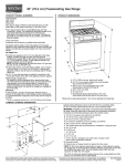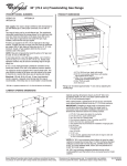
1
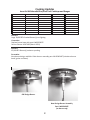
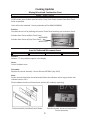
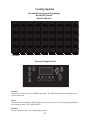
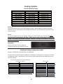
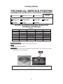
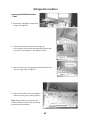
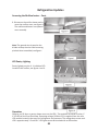
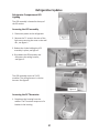
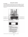
UD-40 Service Update Second Half — 2010 Prepared by: WHIRLPOOL CONSUMER CARE PART NO. W10349156 Forward The following service update information is provided to make you more knowledgeable about the Whirlpool family of major appliances. Service update information is designed for the experienced service specialist. It keeps you advised of the most recent improvements and product changes, and allows you to service these products more efficiently. WHIRLPOOL CORPORATION assumes no responsibility for any repairs made on our products by anyone other than authorized In-Home Service Professionals. ®Registered trademark/™ Trademarks of Whirlpool, U.S.A., KitchenAid, U.S.A., Jenn-Air, U.S.A., or Maytag Corporation or its related companies. © 2010 All rights reserved. Whirlpool Corporation, Benton Harbor, MI 49022 - ii - Table Of Contents Cooking Updates.............................................................................................................................. Page 1 Jenn-Air Built-In Ovens................................................................................................................ Page 1 F1 E1 Failure Code appears on display..................................................................................... Page 1 Jenn-Air & KitchenAid Gas/Dual Fuel Cooktops and Ranges..................................................... Page 1 Large 20,000 BTU Stacked Burner(s) not lighting.................................................................... Page 1 15,000 BTU Burner(s) nuisance sparking................................................................................. Page 1 Maytag MicroHood Combination Oven...................................................................................... Page 2 5100 Stainless steel models..................................................................................................... Page 2 Jenn-Air Dedicated Microwave Ovens........................................................................................ Page 3 Number “3” may randomly appear in the display................................................................... Page 3 Jenn-Air Slide-In Ranges.............................................................................................................. Page 4 The keypads are too light, and difficult to see......................................................................... Page 4 Gas and Electric Freestanding Ranges........................................................................................ Page 5 No AM/PM Feature . ............................................................................................................... Page 5 Electronic Range Control............................................................................................................. Page 5 Customer can not set clock for AM/PM operation.................................................................. Page 5 Jenn-Air Built-In Ovens................................................................................................................ Page 6 The DELAY feature with COOK TIMER does not work.............................................................. Page 6 Induction Cooktop....................................................................................................................... Page 6 Induction Cooktop Configuration Label................................................................................... Page 6 Pointers........................................................................................................................................ Page 7 K4317483................................................................................................................................. Page 7 K8178811................................................................................................................................. Page 8 Fabric Care Product Updates......................................................................................................... Page 11 VMW HE Washer - Updates........................................................................................................... Page 11 Cabrio®/Bravos® Burner Tubes.............................................................................................. Page 12 Lid Locked on Delivery........................................................................................................... Page 12 Washer Installation Instructions............................................................................................ Page 13 Reminders.................................................................................................................................. Page 14 Sounds................................................................................................................................... Page 14 Low Wash Water Technology................................................................................................. Page 14 Automatic Load Sensing........................................................................................................ Page 16 Direct Drive TL Washer - Updates................................................................................................. Page 17 Standard Pressure Switch/Hose............................................................................................. Page 17 Siphoning - AND..................................................................................................................... Page 17 Repeat Load Sense/ATC Failures............................................................................................ Page 17 Home Plumbing Noise........................................................................................................... Page 18 VMW Classic Washer - Updates.................................................................................................... Page 19 Impeller vs. Agitator Differences:.......................................................................................... Page 19 Reminders.................................................................................................................................. Page 20 Remember – Agitation Strokes are Variable.......................................................................... Page 20 Console Access...................................................................................................................... Page 20 Tight Spanner Nut!................................................................................................................ Page 21 Front Load Washer - Updates........................................................................................................ Page 22 Shocks – 36” Belt Drives........................................................................................................ Page 22 Techline Tip............................................................................................................................ Page 22 Duet Door Leak – Newer Models.............................................................................. Page23 Amana & Inglis.......................................................................................................... Page23 Dryer - Updates................................................................................................................. Page24 Two piece heater box assembly................................................................................ Page24 Steam (for Odors & Wrinkles).................................................................................. Page 24 - iii - Table Of Contents (continued) Clean Up Updates.......................................................................................................................... Page 25 Maytag Rework #R254BV...................................................................................................... Page 25 New Hose Fitting - Avoid Leaks.............................................................................................. Page 25 Tall Tub Front Leveling Legs................................................................................................... Page 26 Rack & Tub Discoloration....................................................................................................... Page 26 HE Motor Testing................................................................................................................... Page 27 Checking Connections............................................................................................................ Page 30 Warranty Change................................................................................................................... Page 30 Compactors.................................................................................................................................... Page 32 Replacement Start Switch Kit................................................................................................. Page 32 Refrigeration Updates.................................................................................................................... Page 36 Maytag French Door Refrigerator.......................................................................................... Page 36 MFX2571XEW - MFX2571XEM - MFX2571XEB...................................................................... Page 37 LED Theatre Lighting ............................................................................................................. Page 39 Pantry and Freezer Drawer.................................................................................................... Page 39 Refrigerator Air Flow.............................................................................................................. Page 40 Pantry Air Flow Pattern.......................................................................................................... Page 40 Leveling and Door Alignment................................................................................................ Page 41 Accessing Ice Maker............................................................................................................... Page 42 Ice Maker............................................................................................................................... Page 44 Ice Maker Module.................................................................................................................. Page 45 Accessing pantry drawer light switch.................................................................................... Page 46 Removing the pantry drawer light switch.............................................................................. Page 48 Accessing the Mullion heater................................................................................................ Page 48 LED Pantry Lighting................................................................................................................ Page 50 Operation............................................................................................................................... Page 50 Refrigerator Compartment LED Lighting................................................................................ Page 51 Accessing the RC Thermistor................................................................................................. Page 51 User Interface........................................................................................................................ Page 52 Programming......................................................................................................................... Page 53 Replacing And Timing Pantry Drawer Gear............................................................................ Page 58 Timing the gear drive............................................................................................................. Page 59 Service Pointer Index..................................................................................................................... Page 60 Training Evaluation........................................................................................................................ Page 63 - iv - Cooking Updates Jenn-Air Built-In Ovens JJW2430W JJW2330W JJW2427W JJW2327W JJW2730W JJW2830W JJW2530W JJW2727W JJW2827W JJW2527W JMW2430W JMW2330W JMW2427W JMW2327W JMC2430W JMC2130W JMC2127 JJW3430 JJW3830 JMW3430W *All Colors Concern: F1 E1 Failure Code appears on display Note: At the end of a Timed Bake cycle, the option to add more time or change the oven temperature is made available. If more time is added or the temperature changed F1E1 error code will occur. Solution: Check the following condition Verify the model number saved 1. Enter Diagnostics Mode - press any three keys three times within 8 seconds. 2. Navigate to the System Information Menu and press OK. 3. The current Model Number will appear in the menu list. 4. Highlight model number and press OK. 5. Exit Diagnostics Mode by pressing the BACK button (Main Menu). 6. Select EXIT DIAGNOSTICS and press OK 7. Power unit down for 30 seconds and allow normal power up. 8. Model Number is saved. 1 Cooking Updates Jenn-Air & KitchenAid Gas/Dual Fuel Cooktops and Ranges JDRP430WP00 JDRP436WP00 JDRP536WP00 JDRP548WP00 JGCP430WP00 JGCP436WP00 JGCP536WP00 JGCP548WP00 JGRP430WP00 JGRP436WP00 JGRP536WP00 JGRP548WP00 KDRS407VSS00 KDRS462VSS00 KDRS463VSS00 KDRS467VSS00 KDRS483VSS00 KDRU707VSS00 KDRU763VSS00 KDRU767VSS00 KDRU783VSS00 KGCU407VSS00 KGCU462VSS00 KGCU463VSS00 KGCU467VSS00 KGCU482VSS00 KGCU483VSS00 KGCU484VSS00 YJDRP436WP00 YJDRP536WP00 YJDRP548WP00 YKDRS407WP00 YKDRS467WP00 YKDRU707WP00 YKDRU767WP00 Concern: Large 20,000 BTU Stacked Burner(s) not lighting. Correction: Replace burner base with part # W10320937. Service Pointer K4317483 (March 2010). Concern: 15,000 BTU Burner(s) nuisance sparking. Correction: New burner design available. Order burner assembly part # W10342487 (includes a burner head, ignitor and base). Old Design Burner New Design Burner Assembly Part # W10342487 (no burner cap) 2 Cooking Updates Maytag MicroHood Combination Oven Model: MMV1164WS Concern: 5100 Stainless steel models were built with a Gray Touch Panel instead of the Black Touch Panel as specified. Units will not be reworked. Future production will be MMV1164WS01. Solution: Complete service call by ordering the correct Touch Panel assembly per customers choice. Stainless Steel Frame w/Black Touch Panel - W10340660 Stainless Steel Frame w/Gray Touch Panel - W10315762 Jenn-Air Dedicated Microwave Ovens JMC2430W*00 JMC2430W*01 JMC2130W*00 JMC2127W*00 Concern: Number “3” may randomly appear in the display. Cause: Control software issue. Correction: Replace the control assembly. Service Pointer K8178811 (July 2010) Note: Service controls have been corrected and will have the software version tag as shown that indicates version 1.0.2. Earlier software versions will have issues with the # 3 randomly appearing. Control assembly includes all parts shown. Revision Number shown on replacement Control Assembly. 3 Cooking Updates Jenn-Air Slide-In Ranges Concern: The keypads are too light, and difficult to see. Cause: Color graphics are not bright enough. Solution: The User Interface is being changed to more contrasting colors. There will be an engineering dash change when the new user interface is available. New Console assemblies are available as listed in the chart below. Current console assemblies, from parts lists, sub to the new part numbers listed. Jenn-Air Slide-In Ranges Model New Part # JDS8850CDS00 JDS9860CDS00 JES8750CAS00 JES8850CAS00 JES8860CCS00 JES9750CAS00 JES9800CAS00 JES9860CAS00 JES9860CCS00 JES9900CCS00 JGS8750CDS00 JGS8850CDS00 JGS9900CDS00 W10314414 W10314421 W10314412 W10314415 W10314416 W10314422 W10314417 W10314420 W10314420 W10314418 W10314413 W10314414 W10314419 *Only Stainless Steel models affected 4 Cooking Updates Gas and Electric Freestanding Ranges No AM/PM Feature Models Affected: AER5522VA*0 AER5522VC*0 AER5524XA*0 AER5821VA*0 AER5822VA*0 AER5822VC*0 AER5823XA*0 AER5823XC*0 AER5830VA*0 AER5844VA*0 AER5844VC*0 AER6011VA*0 AGR5844VD*0 AGR5844VD*1 AGR6011VD*0 AGR6011VD*1 IES350XW0 IVE32300 IVE82300 IVP33800 IVP85800 IVP85801 MER5605W*0 MER7651W*0 MER7661W*0 MER7661W*1 MER7662W*0 MER7662W*1 MER7765W*0 MER7765W*1 MER7775W*0 MER7775W*1 MER8770W*0 MER8770W*1 MGR7661W*0 MGR7661W*1 MGR7662W*0 MGR7662W*1 MGR7665W*0 MGR7665W*1 MGR7775W*0 MGR7775W*1 MGR8670W*0 MGR8670W*1 RF114PXS*2 RF114PXS*3 RF212PXS*3 RF212PXS*4 RF214LXT*0 RF214LXT*1 RF260BXS*2 RF262LXS*2 RF262LXS*3 RF262LXS*4 RF263LXT*2 RF263LXT*3 RF263LXT*1 RF263LXT*2 RF263LXT*3 RF264LXS*1 RF264LXS*2 RF264LXS*3 RF265LXT*2 RF265LXT*3 RF272LXT*2 RF272LXT*3 RF362LXT*2 RF362LXT*3 RF367LXS*3 RF367LXS*4 RF462LXS*3 RF462LXS*4 SF265LXT*0 SF265LXT*1 SF265LXT*2 SF272LXT*0 SF272LXT*1 SF272LXT*2 SF362LXT*0 SF362LXT*1 SF362LXT*2 SF367LXS*1 SF367LXS*2 SF462LXS*1 SF462LXS*2 TEP340V*0 TES325V*0 TES326V*0 TES355V*0 TES356V*0 TGS325V*0 TGS325V*1 TGS326V*0 TGS326V*1 TEP340V*0 TES325V*0 TES326V*0 TES355V*0 TES356V*0 TGS325V*0 TGS325V*1 TGS326V*0 TGS326V*1 WERC4101S*1 WERC4101S*2 WERC4101S*3 WERE3000S*1 WERE3000S*2 WERP3101S*1 WERP3101S*2 WERP4101S*1 WERP4101S*2 WERP4101S*3 WERP4110S*1 WERP4110S*2 WERP4110S*3 WFE114LW*0 WFE321LW*0 WFE324LW*0 WFE301LV*0 WFE361LV*0 WFE364LV*0 WFE366LV*0 WFE371LV*0 WFE374LV*0 WFE381LV*0 WFG361LV*0 WFG361LV*1 WFG361LV*0 WFG361LV*1 WFG366LV*0 WFG371LV*0 WFG371LV*1 WFG374LV*0 WFG374LV*1 WFG381LV*0 WFG381LV*1 YIES350XW0 YMER7651W*0 YMER7651W*1 YMER7660W*0 YMER7660W*1 YMER7662W*0 YMER7662W*1 YMER7765W*0 YMER7765W*1 YMER8770W*0 YMERH770W*0 YMERH770W*1 YRF115LXV*0 YRF263LXT*0 YWFE301LV*0 YWFE361LV*0 YWFE366LV*0 YWFE371LV*0 YWFE381LV*0 * All Colors Electronic Range Control Concern: Customer can not set clock for AM/PM operation. The U&C guide describes setting the control for AM or PM. Cause: This feature was removed in 2008 and the literature is incorrect. The literature going forward has change to state “ ON SOME MODELS ”. Solution: Do not change control. Unit is operating correctly. 5 Cooking Updates Jenn-Air Built-in Ovens JJW2430W JJW2330W JJW2427W JJW2327W JJW2730W JJW2830W JJW2530W JJW2727W JJW2827W JJW2527W JMW2430W JMW2330W JMW2427W JMW2327W *All Colors Concern: The DELAY feature with COOK TIMER does not work. When setting this feature and after PREHEAT you are instructed to insert food and PUSH start, but if customer is not home they cannot do that. Cause: For JennAir Models with the 4” display, if they set a COOK TIMER and a DELAY, then when the oven gets to temperature, the timer is NOT going to start until the door is opened and closed, or the timer start button is pressed. So there is no way for the timer to start on its own for a delay start. Correction: None at this time. This is a software issue and engineering is working on a fix. Induction Cooktop Configuration Label Models: ICI500X*00, KICU500X*00, GCI3061X*00 The tech sheets used in the first production of Induction Cooktops has an incorrect Cooktop Configuration label. Listed below is the incorrect label used and the new label with the correct information. Incorrect information used on first production of Induction Cooktops. Currently Information on Tech Sheets in Warehouses Configuration Number Cooktop Model 19 20 21 22 23 24 25 26 Correct Label Correct Label Configuration Number Cooktop Model ICI750X ICI500X GCI3061X KICU500X KICU509X JIC4430X JIC4536X KICU569X 20 21 22 23 24 25 26 27 28 29 *= All colors 01 = 01 or greater 6 ICI500X*01 GCI3061X*01 KICU500X**01 KICU509X JIC4430X JIC4536X KICU569X GCI3061X*00 KICU500X**00 ICI500X*00 Cooking Updates TECHNICAL SERVICE POINTER FOR IMMEDIATE ATTENTION OF YOUR SERVICE DEPARTMENT LAUNDRY PRODUCTS K4317483 March 2010 KITCHEN PRODUCTS This Service Pointer Applies To The Following Brands: Whirlpool® REFRIGERATION PRODUCTS KitchenAid Jenn-Air ® Roper® Amana® ® Admiral® Maytag® Magic Chef® JennAir and KitchenAid Gas & Dual Fuel Cooktops and Ranges JDRP430WP00 JDRP436WP00 JDRP536WP00 JDRP548WP00 JGCP430WP00 JGCP436WP00 JGCP536WP00 JGCP548WP00 JGRP430WP00 JGRP436WP00 JGRP536WP00 JGRP548WP00 Models: KDRS407VSS00 KDRS462VSS00 KDRS463VSS00 KDRS467VSS00 KDRS483VSS00 KGCU407VSS00 KGCU462VSS00 KGCU463VSS00 KGCU467VSS00 KGCU482VSS00 KGCU483VSS00 KDRU707VSS00 KGCU484VSS00 KDRU763VSS00 KDRU767VSS00 KDRU783VSS00 YJDRP436WP00 YJDRP536WP00 YJDRP548WP00 YKDRS407VS00 YKDRS467VS00 YKDRU707VS00 YKDRU767VS00 Code Date: Product built before March 2010 (D010) CUSTOMER CONCERN: Large 20,000 BTU Stacked Burner(s) Not Lighting all the time. CAUSE: Large Burner ignition port variation. CORRECTION: Replace Large Burner Base with new replacement part # W10320937. This new base has an added notch behind the ignitor. See Illustrations. Notch ALL POINTERS ONLINE: http://www.servicematters.com/tech_ref/tech_ref_main.htm To receive pointers by email, or to edit or delete a current email address, go to www.servicebench.com ®Registered trademark/™ Trademarks of Whirlpool, U.S.A., KitchenAid, U.S.A., Jenn-Air, U.S.A., or Maytag Corporation or its related companies. © 2010 All rights reserved. 7 Cooking Updates TECHNICAL SERVICE POINTER FOR IMMEDIATE ATTENTION OF YOUR SERVICE DEPARTMENT LAUNDRY PRODUCTS REFRIGERATION PRODUCTS K8178811 June 2010 KITCHEN PRODUCTS This Service Pointer Applies To The Following Brands: Whirlpool® KitchenAid® Amana® Roper® Jenn-Air ® Admiral® Maytag® Magic Chef® The Number “3” Randomly Appears in the Display Models: JennAir Dedicated Microwave Ovens JMC2430W*00 JMC2430W*01 JMC2130W*00 JMC2127W*00 CUSTOMER CONCERN: The number “3” may randomly appear in the display. CAUSE: Control software issue. WARNING CORRECTION: Replace the control assembly. Electrical Shock Hazard Disconnect power before servicing. Replace all parts and panels before operating. Failure to do so can result in death or electrical shock. Control Panel Assemblies by Model and Color Color*/Model JMC2430W*00 JMC2430W*01 JMC2130W*00 JMC2127W*00 B = BLACK S = STAINLESS W10240000 W10240003 W10323051 W10328721 W10240000 W10240003 W10239997 W10239999 R = OIL BRONZE W10240004 W10323050 P = PRO-STYLE W10240003 W10328721 NOTE: Service controls have been corrected and will have the software version tag as shown below that indicates version 1.0.2. Earlier software versions will have issues with the # 3 randomly appearing. ALL POINTERS ONLINE: http://www.servicematters.com/tech_ref/tech_ref_main.htm To receive pointers by email, or to edit or delete a current email address, go to www.servicebench.com ®Registered trademark/™ Trademarks of Whirlpool, U.S.A., KitchenAid, U.S.A., Jenn-Air, U.S.A., or Maytag Corporation or its related companies. © 2010 All rights reserved. 8 Cooking Updates Control assembly includes all parts shown. Revision Number shown on replacement Control Assembly. 9 —NOTES— 10 Fabric Care Product Updates Platform/Model Description Change Due to complexities with new and old model lines, the Platform descriptions have changed to avoid confusion. 11 VMW HE Washer - Updates Thread Lock On Leveling Nut To aid in the manufacturing process the lock nuts will be secured to the threads of the foot with a thread locking compound. It will take a little bit of force to break the nut free if a foot height adjustment is needed. There is no need to use a locking compound on the treads for installation or service adjustments. Lid Locked on Delivery The lids can become locked during transport. If this happens, plug the washer in. Push the POWER button, wait until the LID LOCK light goes out and push the POWER button (to turn the washer off). 12 Washer Installation Instructions These instructions replace Step 2 of the washer: To avoid damaging floor and washer, place cardboard supports from shipping carton on floor behind washer. Use two or more people to tip washer back and place on cardboard supports. Remove shipping base. IMPORTANT: Removing foam shipping base is necessary for proper operation. Orient the sound shield with the edge marked FRONT toward the front of the washer. The words THIS SIDE DOWN should be facing out. Starting with one side, insert the sound shield into the bottom of the washer so that it is behind the frame. Stand the washer upright. 13 Reminders Sounds Remember that the new HE Belt Drive washers use less water (many customers will notice) and that they do not sound the same as any prior washers that we have made. Get yourself familiar with the sounds of these new washers. Don’t forget that the agitation strokes are variable, dependant on Cycles selected, Options selected and the input readings to the control. Low Wash Water Technology Uses Less Water • About 2” of washplate • Not all of the clothes will be under water Remember that the new HE VMW’s use less water. A proper water level will leave about 2” of the washplate NOT under water. Not all of the clothing will be under water – it is NORMAL for some clothes to be wet and above the water level line. Uses 20-66% of the water (vs. Traditional Washer) Approx 16-18 Gallons (vs. 40-45 Gallons) Long term savings! Water and energy savings from an HE washer are equivalent to the cost of the dryer! Water Level 14 Reminders Low Wash Water Technology • • • • Uses Less Water Uses Less Energy -These washers use less energy through ramping and coasting the spin, the use of an efficient Permanent Split Capacitor Induction motor and tighter control of water temperatures and water levels. Produce Better Cleaning Results -Less Water + Full Dose of HE Detergent equals BETTER cleaning results!!!! Gentler On Clothes -Non agitator washers are proven to be gentler on clothes (a slower agitation rate is possible in these washers due to the concentrated solution and low water levels). Low Wash Water Technology TRUST THE SOFTWARE !!!!!!!! -100 years of clothes cleaning experience -Billions of loads -TRUST THE SOFTWARE !!!! -Select the correct cycle and options -TRUST THE SOFTWARE !!!! -DO NOT add Water -Too Much Water = Cleaning Complaints -Reduced Mechanical Energy -(clothes will float) -Diluted Detergent -Cycle Algorithms Remember: TRUST THE SOFTWARE!!!!!! Whirlpool has a hundred years of clothes cleaning experience and has experimented with cleaning billions of loads of clothes. If you are handling a “cleanability” complaint, make sure that the customer has used the correct cycle, selected the correct modifiers and is using chemicals correctly. Do not try to fool the machine by finding ways to fill the unit with more water. You will be fighting 100 years and billions of cycles of experience. TRUST THE SOFTWARE!!! Selecting a (wrong) cycle just because it uses more water also selects the wrong agitation profile, wrong time profile and wrong spin profile for the fabric type, load size and soil level. 15 Automatic Load Sensing From START button push to water entering the washer may take: - No load in the washer up to 2 minutes - 18 pound load up to 3 minutes If the lid is opened during the child entrapment the machine will go into the pause mode. To avoid additional delays the lid needs to remain shut during the sensing mode. 16 Direct Drive TL Washer - Updates Standard Pressure Switch/Hose Pressure Hose off? Replace hose and switch. Use all kit parts. Do not simply reattach a fallen pressure switch hose to the pressure switch and consider the repair complete. You must replace the pressure switch hose and pressure switch. Anytime that you find a pressure switch hose that is damaged, cut, too short, disconnected, etc. it must be replaced. Cutting off the end of a pressure hose and/or stretching the hose to fit (removing the slack) increases the risk that the hose may become detached. When ordering replacement hoses or a pressure switch, on some models, it will come as a kit. It consists of a new hose of the correct length, a new barbed pressure switch and a clamp. You must use all of the parts in the kit for a proper repair. Siphoning - AND... When installed improperly, the washer can get stuck in a siphon mode Repeat Load Sense/ATC Failures If you get a Load sense washer that has repeated (ATC) switch failures, be sure to have the tech check for a possible drain siphoning situation, in certain instances, if the washer has a siphoning issue and continues to fill for a long extended period of time, it will cause the control in the switch to fail. In these cases, have the tech secure the drain hose so there is no way a siphon effect can start and replace the switch again. Of course it is always important to check all aspects of the customers electrical supply, right there at the washer. 17 Repeat Load Sense/ATC Failures (continued) Reverse polarity (at the home electrical supply or inside of the washer) will cause repeat Load Sense/ATC failures. Make sure that polarity is not reversed at the power supply, the power cord, the noise filter or the harness pin connectors. Home Plumbing Noise All current stock of Load Sense Switches (as of 6/11) have had software adjustments to correct for repeat failures and to reduce home plumbing noise. 18 VMW Classic Washer - Updates Sept/Oct 2010 VMW classic top load washers. The VMW is now being manufactured with an agitator. Impeller vs. Agitator Differences: Differences between the agitator and the impeller models are: • An agitator instead of an impeller. • The Basket – it is very similar to the Direct Drive basket. • The Tub – is shorter for the agitator style Basket. • The Suspension – is shorter for the shorter Tub. • The Gearcase – it has taller agitator shaft • Drive Block and Spanner Nut the same as the Direct Drive’s. • Drive Motor –it is a 1/4hp motor (Impeller model uses a 1/3hp) • The software – is for an agitator Console access. 19 Reminders Remember – Agitation Strokes are Variable Don’t forget that the agitation strokes are variable, dependant on Cycles selected, Options selected and the input readings to the control. Console Access The rear consol cover is tabbed at the top and held in at the bottom with three screws. Release the front panel clips to free the console. Remember: To NOT damage the wires or pressure hose, remove the wire cover prior to lifting the top. Remove Cover 20 Tight Spanner Nut! Reuse old spanner nut whenever possible. Tighten following these instructions. Use silcone grease on the threads – Truck Stock part number 542638 Hand Tighten Make a positioning mark on the drive block and hand tightened spanner nut. Tighten with a hammer. Tighten until 1/2” BEYOND the mark! Tighten until you have rotated the spanner nut 360° around and taken the spanner nut mark ½” beyond the mark on the drive block. 21 Minimum 360o Plus 1/2” Front Load Washer - Updates Control software has changed to meet new energy requirements. This affects replacement parts. All new controls no longer have a Warm/Warm option in the Normal Cycle. Shocks – 36” Belt Drives Not all front loaders are engineered to have four shocks. Even though a fourth shock may be physically added to these washers (they have the same base and tub), it may negatively effect cycle times. There have been reports of techs changing tubs when adding a fourth shock because they are concerned (unnecessarily) about the bearings. Techline Tip 22 Duet Door Leak – Newer Models • • • • • • • Replace Bellow Proper Position (no twists) Tight clamps (do not over tighten) Clean Bellow Tight Hinge Screws Test door alignment (RinseAid) Ø Replace Front Newer Duet washers leaking from the door; Be sure the bellows has been replaced, is positioned properly without any twists, be sure clamps are secured properly without over tightening the screw type clamp on the tub side. Be sure the bellows is clean and that all hinge screws are tight, be sure door itself is aligned squarely with the washer front/bellows. A good test for door closing is this, open the door, apply rinse agent to the face of the bellows, close the door normally, reopen it and see if there is evidence of full contact on door glass where bellows makes contact, adjust/tweak the door if an area is found with no sign of contact. Follow this procedure unless the product you are dealing with is older. Do Not recommend replacing washer fronts on models newer than serial code HLT unless there is an obvious issue with it. Amana & Inglis Amana and Inglis Front Load washers have changed from Samsung built to Whirlpool (Monterrey) 36” Direct Drive built. 23 Dryer - Updates WED9270XWO M02512746 through M02512795 and M02517338 through M02517362 Several dryers may have been built with a two piece heater box assembly instead of a one piece heater box assembly. The two piece and one piece heater boxes are interchangeable. Be careful when looking up parts if you need to order one. Steam (for Odors & Wrinkles) The Steam dryer software is going through a running software change. To let the customer know that the steam cycle is working, it will spray a mist at the start of the cycle. It will be some time before Use and Care Guides will reflect this change. 24 Clean Up Updates Maytag Rework #R254BV Console Insert Quality MDB4709AWW MDB6709AWW MDBH949AWW MDB7809AWW MDC4809AWW Serial Range FY39 - FY43 The insert on the Console may have been manufactured with incorrect material. If the customer calls with complaint that the Console Insert is discoloring, order and replace the Console assembly. Use the chart to determine the correct Console part number for the model being repaired. Models: Console Number: MDB4709AWW W10254834 MDB6709AWW W10254837 MDBH949AWW W10254824 MDB7809AWW W10199785 MDC4809AWW W10255080 Upon completion of the repair, indicate R254BV on your work order and submit for payment through normal procedures. New Hose Fitting - Avoid Leaks DO NOT OVER TIGHTEN THE FITTING Hand tight then: ¼ to ½ Turn Remember: It is advised to only turn the new fitting ¼ to ½ turn past hand tight. Over tightening may cause a leak. 25 Tall Tub Front Leveling Legs Helpful Tip: Run the leveling legs out and then back in prior to placing dishwasher under counter. Ensure leveling leg moves freely prior to placing unit under counter: Run the leveling leg out and then back in using a 6 point socket on the foot. (This removes debris that could cause locking of the leveling legs.) Rack & Tub Discoloration • Plastic tub dishwashers are “whiter” than in the past. • Tomato based foods may cause “pink” staining. Staining may be more visible than in the past. • Plastic tubs “cure” within 30 to 40 cycles (about one month) and become more resistant to pink staining. • ink staining will disappear over time depending on how often the P consumer washes tomato based stained dishes. Due to low sales volumes Proctor and Gamble® has dropped Cascade Plastic Booster® from their product line-up. active ingredient: Benzol Peroxide • Whirlpool is working to find an alternate solution. • 26 HE Motor Testing Ohming HE Motor is not possible This is because it is not possible to ohm out a HE wash motor. There is no direct access to the windings from the terminals. The harness connection is the edge of a computer board. Any readings taken from here will show an open circuit. 27 HE Motor Testing The best and fastest way to test the motor is to enter the diagnostic mode. Intervals 20, 17,16,13,12 and 11 are all steps that turn on the motor. If the motor turns on in any of these steps, you KNOW that the motor is OK. 28 HE Motor Testing If it doesn’t turn on, you can take some quick power checks while you have the motor circuit energized in diagnostics. From the control area, you should read line voltage from P5 on the control to both sides of the in-line resistor. If you do have line voltage then the problem will be in the motor or the connecting harness. If you don’t have line voltage, trace the problem to something before these spots, like door switches, motor fuse or splice connections. For the most accurate voltage check, check at the motors P3 (Blue) connector to both the P2 (White/Violet or White) connector and the P1 (Blue/White) connector. If you read voltage here and the motor does not operate, then the motor will need replacement. If you don’t see voltage at these points, your problem is elsewhere. 29 Checking Connections OK Not OK Don’t forget that poor RAST pin connections can cause components to not work and lead to mis-diagnosis. Warranty Change 30 Warranty Change Maytag 10 Year Limited Warranty SS Tub Interior, Chopper and Racks MDB7609AWW/B/S MDB7709AWW/B/Q/S* MDB7809AWW/B/Q/M* MDB8859AWW/B/S* MDB8959AWW/B/S MDB7759AWW/B/S MDBH979AWW/B/S MDBH989AWW/B/Q/S (retroactive warranty on existing models) Models began on: September 9, 2009 30-Day Money Back 30 Day Quiet Money Back Guarantee Maytag and Whirlpool Brands offer a Dishwasher 30 Day Quiet/Performance Money Back Guarantee on specific models. Maytag added the guarantee this month. Whirlpool has offered this guarantee for several years. 31 Compactors Replacement Start Switch Kit Replacement parts sub to new kit - #W10342596 1 Normally closed switch 1 Actuator assembly 1 Toe guard 1 Template 2 Screws 1 Instruction Sheet Starting in the second quarter, compactors went to a new integrated switching redesign. The switch has changed from a normally open switch to a normally closed switch that is held open by a new actuator lever. Replacement parts for the old switch will sub to a kit that contains: a normally closed switch, an actuator assembly, toe guard, a template, two screws and an instruction sheet. Remove Front After removing the drawer and top panel, remove the front panel. 32 Replace Switch Machine Front Switch orientation is with terminals pointed up. Screw Hole Template Machine Front Template (2) 3/32” Holes Place the template over the switch and drill two 3/32” holes for the new actuator. 33 New Actuator Install the new actuator. Remove Old Actuator Screws Old Actuator Blade Remove the old actuator blade from the Foot Pedal. 34 New Toe Guard Toe Guard Screws Toe Guard Replace the old Toe Guard with the one provided in the kit. Finished Modification Complete your work, test the operation and clean up your work area. 35 Refrigeration Updates Maytag French Door Refrigerator Ice And Water In The Door External Entry Pantry Drawer MFX2571XEB MFX2571XEM MFX2571XEW Dimensions In. Cutout Width (in) 36 Depth 35 5/8 Height 70 1/8 Width 35 5/8 Depth Closed Excluding Handles 32 7/8 Depth Closed Including Handles 35 5/8 Depth Excluding Doors 29 Depth With Door Open 90 Degree 48 Height To Top Of Cabinet 68 5/8 Height To Top Of Door Hinge 70 1/8 Width of Cabinet Only 35 5/8 10 Year Compressor Warranty 1 Year Parts and Labor 2nd through 10th year Compressor is warranted but not labor 36 Refrigeration Updates MFX2571XEW - MFX2571XEM - MFX2571XEB 25% E-Star Always refer to the Technical Information shipped with the product for specific information for the product you are servicing. 37 Refrigeration Updates 38 Refrigeration Updates LED Theatre Lighting A LED lighting module is located on the top of the cabinet in the RC and 4 individual LEDs are mounted in the mullion divider and focused on the interior of the pantry drawer. Pantry and Freezer Drawers New pantry drawer design allows accessibility to items with out opening the refrigerator compartment doors. The pantry level makes it easy for children to access drinks and snack items. The freezer compartment and drawer are identical to previous Iceland product 39 Refrigeration Updates Refrigerator Air Flow Cold air enters the ice maker compartment, circulates and then enters the RC compartment, see figure 1. Pantry Air Flow Pattern Cold air enters the pantry around the perimeter of the glass shelf see figure 2, there are no dedicated inlet vents. The return air ducts are located in the bottom of the RC compartment in the left and right hand side corners, see figure 3. Figure 1 Figure 3 Figure 2 40 Refrigeration Updates Leveling and Door Alignment Left RC Door Removal Door removal is identical to previous models. The water dispenser tube and UI wiring harness are routed under the left door hinge. 1. Disconnect power to the refrigerator. 2. Remove cover screw and cover – Figure 1. 3. Disconnect water tube and wiring harness – Figure 2. 4. Remove 3 5/16” hinge screws and remove door – Figure 3. Figure 1 Figure 2 41 Figure 3 Refrigeration Updates Accessing Ice Maker The ice maker assembly is similar to what was used in previous Iceland refrigerator. A Whirlpool ice maker is used with a few variations which are highlighted in this section. Removing Ice Bin 1. Disconnect power to the refrigerator. 2. Depress the release but ton, see figure 1. 3. Slide out the ice bin as- sembly, see figure 2. 4. Insert straight blade screwdriver into slot and press down on locking tab and at the same time pull the cover toward you. See figure 3. 5. Disconnect wiring harness. Figure 4. 6. Release locking tab as you pull out the ice maker. Figure 5 42 Refrigeration Updates 7. Slide out the ice maker assembly, see figure 6. Figure 6 8. After removing the ice maker check to see if the air outlet duct gasket was dislodged, see figure 7. Figure 7 9. After replacing the ice maker, Install the duct gasket by removing the air discharge grill from the refrigerator compartment side of the icemaker compartment. See figure 8. Figure 8 Complete ice maker assembly. 43 Ice Maker Refrigeration Updates A Whirlpool ice maker similar to previous production (with noted changes) is used on this new refrigerator. A sixteen finger ejector blade is used to prevent cubes hanging up or remaining in the mold. 44 Refrigeration Updates Ice Maker Module The ice maker module is similar to what is being used. The harvest sensor unplugs from the module. A harvest can be initiated by jumping across “T” and “H” on the module. Always refer to the ice maker tech sheet for detailed instructions. To remove the air duct: Remove the 3 ¼” hex head screws securing the air duct to the ice maker mold and separate. Note: When assembling the air duct install the wiring harness into the duct. 45 Refrigeration Updates Accessing pantry drawer light switch 1. Disconnect power to the refrigerator. 2. Push up on the pantry glass shelf from underneath, see figure 1. 3. Slide out the glass shelf and set aside, see figure 2. Note: Everything is tied into the left side cover, it must be removed first, see figure 4. 5. Insert straight blade screwdriver into the three slots in the left side cover , beginning with #1 and pry down as you pull the cover out and away from the cabinet and up. Repeat the process with slots #2 and #3. See figure 5. 46 Refrigeration Updates Accessing pantry drawer light switch – Cont. 6. Pop off the cover, see figure 6. Note: You may hear a loud cracking noise as the cover breaks loose. Figure 7 is a view of the back of the cover showing the top and bottom locking tabs. 7. Remove the rear cover by lifting up and out beginning with the corner of the cover, see figure 8. Drawer Switch Operation 47 Refrigeration Updates Removing the pantry drawer light switch. Disconnect the power to the refrigerator. 1. Use a straight blade screwdriver to depress the locking tab on the side of the light switch and push the switch through the bracket. See figure 1. 2. Disconnect the wire harness and remove the switch. Accessing the Mullion heater Follow the steps previously outlined to remove left side cover. Figure A 1. Remove the pantry drawer panel: Back top screws ½ way out Remove lower screws Lift off the panel, see figure B. Note: this step is optional, the panel can be left in place. 48 Refrigeration Updates Accessing the Mullion heater – Cont. 2. Remove the refrigerator doors and hinges . See figure C. 3. A reinforcement bar extends across the top of the mullion and must be removed. Release the bar from the 2 retaining clips . See figures D and E. 4. Remove the bar by swinging out the left side first and then the right side, see figure F. 5. Roll out the mullion out far enough to disconnect the green chassis ground Note: The ground wire is taped to the divider to keep the wire From becoming pinched when assembled 49 Refrigeration Updates Accessing the Mullion heater – Cont. 6. Disconnect the mullion heater and re move the mullion cover, see figure H. The mullion and heater are replaced as an assembly. Note: The ground wire is taped to the divider to keep the wire from becoming pinched when assembled, see figure I. LED Pantry Lighting Pantry lighting consist of 4 individual LED located in the mullion, see figures J and K . Operation Opening an RC door or pantry drawer turns on the LEDs . The modules are wired in series, if 1 LED fails all 4 will not illuminate. Operating voltage (18 Volts DC) is supplied from the main LED module located in the top of the refrigerator compartment. The voltage drop across each LED is approximately 3.5 volts D.C. LED lights cannot be checked with an Ohmmeter . 50 Refrigeration Updates Refrigerator Compartment LED Lighting The LED assembly is located in the top of the RC section. Accessing the LED assembly 1. Disconnect power to the refrigerator. 2. Remove the ¼” screw in the rear of the light cover securing the cover to the cabi net , see figure 1. 3. Release the 4 tabs holding the LED assembly in place, see figure 2. 4. Drop down the LED assembly and disconnect the wiring harness, see figure 3. The LED assembly consist of 2 LED modules. The wiring harness is a 4 wire harness. See figure 4. Accessing the RC Thermistor 1. Drop down the housing from the cabinet. The Thermistor snaps out of a bracket in the housing. 51 User Interface Refrigeration Updates The user interface hardware is identical to some current models, see figure 1. The exception is the new ”Stealth” software. The new software encompasses revised graphics, Icons and animation. The program is consumer friendly and easy to use. A few minutes reviewing the Use and Care manual and experimenting programming the control is all that is needed to be able to access and use all the built in features. A few of the screens are highlighted in the following section. Example of Use and Care Information (Figure 2). Note: these are only a few examples of the many screens available. 52 Refrigeration Updates Programming The user interface display goes into hibernation (Sleep Mode) after 2 minutes if there is no activity. The first press of a control button or the display screen will reactivate the screen., see figure 3. Additional presses of the control buttons or display screen change the applicable settings. Quick Tips The following screens are examples of the quick tips feature . These are in random order. Screen One Screen Two Option of choosing Interior or Exterior features 53 Refrigeration Updates Screen Three Interior features chosen, 2 pages of selections available. Screen Four Exterior features chosen, 3 selections available. Screen Five Exterior features; LCD touch screen selected. Screen Six Additional features selected. Note: these are only a few examples of the many screens available. 54 Refrigeration Updates Nutrition The following screens are examples of the Nutrition feature . These are in random order. Screen One Food groups are displayed. Screen Two Dairy selected, milk selected. 2 pages of information. Page 1. Screen Three Dairy selected, milk selected. 2 pages of information. Page 2 Note: these are only a few examples of the many screens available. 55 Refrigeration Updates Nutrition The following screens are examples of the Nutrition feature . These are in random order. Screen One Options selected; Page 1 of available options. Screen Two Use and Care option selected, 6 selections. Screen Three Refrigerator & Freezer - use and care selected,4 selections. Note: these are only a few examples of the many screens available. 56 Refrigeration Updates Screen Four Page 2 of available options. Screen Five Ice maker option selected. Customer can toggle the ice maker ON/Off. Note: The previous screens were only a small example of the screens available. Always refer to the Use and Care manual shipped with the product for specific information for the product you are servicing . 57 Refrigeration Updates Replacing and timing pantry drawer gear 1. Remove the pantry drawer. 2. Insert a straight blade screwdriver into the slot in the gear cover and press down to disengage the cover from the gear, see figure 1. 3. Remove the cover, see figure 2. 4. Unsnap the connector bushing and slide it toward the center of the connecting rod to expose the slot in the gear, see figure 3. 5. Lift the connecting rod out of the gear, see figure 4. 6. Unsnap the gear from the axle, see figure 5. 58 Refrigeration Updates Timing the gear drive A new timing procedure has been engineered into the pantry drawer gear drive system. To time the drive: 1. Locate the hole in the drive gear above the gear tooth with the raised edge, see figure 1. 2. Locate the tear drop on the adaptor rail, see figure 2. 3. Align the hole in the gear with the tear drop on the adaptor and snap into place, see figure 3. 4. Move the opposite adaptor and gear in or out until the connecting rod aligns with the slot in the replacement t gear. 59 Service Pointer Index Cooking BRAND & ID# Jenn-Air K8178799 KitchenAid K4317476 Whirlpool, Maytag K8178800 KitchenAid, Jenn-Air K4317483 Whirlpool, Maytag K8178800A DESCRIPTION DATE ISSUED JennAir Gas-on-Glass Cooktops, Glass Cooktop Breaking (see model list attached to pointer) Under certain conditions the ceran glass cooktop may break. 1/10 KitchenAid MicroHood Combination (MHC) Oven (see model list attached to pointer) Microwave starts and runs on its own 1/10 All Whirlpool and Maytag Freestanding Self-Clean Gas Ranges Built since - July 2008 / Beginning Code Date RW27 Moisture Dripping from the Door Window 3/10 JennAir and KitchenAid Gas & Dual Fuel Cooktops and Ranges (see model list attached to pointer) Large 20,000 BTU Stacked Burner(s) Not Lighting all the time. 3/10 All Whirlpool and Maytag Freestanding Self-Clean Gas Ranges Built since - July 2008 / Beginning Code Date RW27 Moisture Dripping from the Door Window 5/10 Jenn-Air K8178811 JennAir Dedicated Microwave Ovens (see model list attached to pointer) The Number “3” Randomly Appears in the Display Control software issue. 6/09 BRAND & ID# DESCRIPTION Maytag L8178802 Maytag Bravos Gas and Electric Dryers (see model list attached to pointer) Excessive Noise or Vibration Fabric Care DATE ISSUED Jenn-Air, Maytag, Amana, Admiral, Magic Chef L8178803 Plastic Tub Dishwashers (U.S. only), (see model list attached to pointer) Heating Element and BrackeRework #R173BV Whirlpool, Maytag, Amana, Admiral, Roper L8178818 Top Load Washers with a Dispenser (see model list attached to pointer) No Agitation, Not Spinning, Wet Clothes or No Draining Complaints 60 3/10 6/10 7/10 BRAND & ID# Whirlpool L8178808 DESCRIPTION DATE ISSUED Vertical Modular Washers All Models Locked Lid after Delivery or Uncrating 6/10 Cabrio Washers WTW7340X* C01170000 through C01570819 Techsheet Error 7/10 Whirlpool, Maytag, Amana, Roper, Admiral, L8178817 Top Load Washers with a Dispenser Drawer (see model list attached to pointer) Washer not filling at start of the cycle 7/10 Whirlpool L8178804 Clean-Up BRAND & ID# DESCRIPTION Whirlpool, KitchenAid, Jenn-Air, Maytag K4317482 Whirlpool Built Stainless Steel Dishwashers (see model list attached to pointer) Lower Dish Rack Falls Off Tub Rail DATE ISSUED 2/10 Maytag L8178809 Maytag Dishwashers MDB4709AWW MDB6709AWW MDBH949AWW MDB7809AWW MDC4809AWW Console Insert Quality Rework #R254BV 6/10 Whirlpool L8178804 Cabrio Washers WTW7340X* C01170000 through C01570819 Techsheet Error 7/10 Refrigeration BRAND & ID# DESCRIPTION DATE ISSUED Whirlpool, Maytag R4317480 Bottom Mount Freezer Refrigerators Technical Data Sheet Location 1/10 KitchenAid, Jenn-Air R4317481 KitchenAid, Jenn-Air R4317484 KitchenAid and Jenn-Air Built In Refrigerators Door Alarm Circuit Operation 1/10 Jenn-Air and KitchenAid Built In Refrigerators (see model list attached to pointer) Freezer Drawer Hard to Open or Close 3/10 27’ French Door Refrigerator With In Door Ice Moisture or Frost Build Up 3/10 Whirlpool, Maytag, Amana R8178801 22’ and 25’ SXS Refrigerator Push Button Water Filter (see model list attached to pointer) Refrigerator lower hinge cover rubs against grille 3/10 KitchenAid, Jenn-Air R4317486 6/10 Whirlpool, Maytag R8178796 KitchenAid Built In Bottom Mount Freezer Refrigerators KBFC42FTS KBFO42FTX Scrapping Noise When Opening Door 61 Refrigeration (continued) BRAND & ID# DESCRIPTION Whirlpool, Maytag, KitchenAid, Jenn-Air, Amana R4317489 19, 22 and 25 cu. ft. Bottom Mount Freezer Refrigerator Drawer Operationr KitchenAid, Jenn-Air R4317485 Jenn Air and KitchenAid Built In Refrigerators (see model list attached to pointer) The Touch Sensor User Interface may fail to power up DATE ISSUED 6/10 6/10 Whirlpool, Maytag, KitchenAid, Jenn-Air, R8178812 Whirlpool, Maytag, and KitchenAid French Door Refrigerators (see model list attached to pointer) Refrigerator does not function correctly after service. 6/10 Maytag, KitchenAid, Jenn-Air, Amana, Admiral, R4317488 All Refrigerators Equipped With Water Dispensers A small amount of water drips out of dispenser after use. 6/10 Whirlpool R8178816 Whirlpool 26’ SXS Refrigerator (see model list attached to pointer) Grinding Noise When Opening Freezer Door 7/10 Whirlpool, Maytag R4317487 Whirlpool 26’ SXS Refrigerator (see model list attached to pointer) Refrigerator lower hinge cover rubs against grille 7/10 Delivery and Installation BRAND & ID# Whirlpool DP8178806 All DP4317490 Whirlpool, Maytag DP8178807 Jenn-Air DP8178810 Whirlpool, Maytag DP8178813 Whirlpool, Maytag DP8178814 Whirlpool, Maytag DP8178815 DESCRIPTION DATE ISSUED Whirlpool SXS 2010 This newly designed refrigerator requires different installation procedures 5/10 All dishwashers equipped with leveling legs, in all Serial ranges Stuck or tight Leveling legs 6/10 All Refrigerators Equipped With Water Dispensers Water drips out of dispenser after initial installation 6/10 Jenn-Air Built In Ovens Shipping material not being removed 6/10 Top Load Washers with Dispenser Drawer WTW5500 WTW5700 MVWX500 MVWX700 Insulation blankets are being mistaken for packing material 7/10 All Front Load, Direct Drive Washers and matching Dryers Pedestal Installation Process 7/10 Top Load Washers with Dispenser Drawer 2 – 3 minute delay in water coming into the washer 7/10 62 TRAINING EVALUATION Please use this page as a reminder to provide us with feedback on today’s meeting. Complete the online evaluation form, located on the Service Matters website @: www.servicematters.com Instructor’s Name: Today’s Training Date: 63