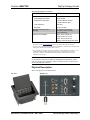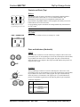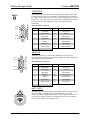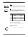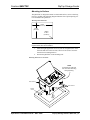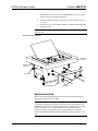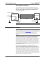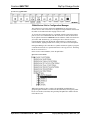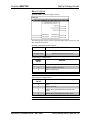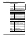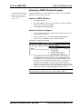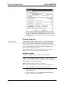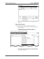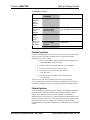
1
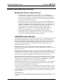
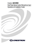
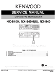
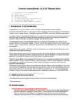
Crestron QM-FTSC
FlipTop Storage Center
Operations & Installation Guide
This document was prepared and written by the Technical Documentation department at:
Crestron Electronics, Inc.
15 Volvo Drive
Rockleigh, NJ 07647
1-888-CRESTRON
All brand names, product names and trademarks are the property of their respective owners.
©2004 Crestron Electronics, Inc.
Crestron QM-FTSC
FlipTop Storage Center
Contents
FlipTop Storage Center: QM-FTSC
1
Introduction ..........................................................................................................1
Features and Functions...........................................................................1
The QuickMedia Transport System .......................................................2
Specifications .........................................................................................4
Physical Description...............................................................................5
Industry Compliance ............................................................................10
Setup...................................................................................................................11
Network Wiring ...................................................................................11
Identity Code........................................................................................12
Installation............................................................................................15
Hardware Hookup ................................................................................18
Ground Wire Connections....................................................................20
Configuration Software ......................................................................................20
Earliest Version Software Requirements for the PC ............................21
Configuring with Crestron SystemBuilder...........................................21
Configuring with SIMPL Windows .....................................................24
Programming with VisionTools Pro-e .................................................31
Example Program.................................................................................31
Adjusting the QM-FTSC Microphone Inputs.......................................31
Uploading and Upgrading ..................................................................................34
Communication Settings ......................................................................34
Uploading a SIMPL Windows Program ..............................................37
Firmware Upgrade ...............................................................................38
Problem Solving .................................................................................................41
Further Inquiries...................................................................................43
Future Updates .....................................................................................43
Return and Warranty Policies.............................................................................44
Merchandise Returns / Repair Service .................................................44
CRESTRON Limited Warranty ...........................................................44
Operations & Installation Guide – DOC. 6269
Contents • i
Crestron QM-FTSC
FlipTop Storage Center
FlipTop Storage Center:
QM-FTSC
Introduction
Features and Functions
The QM-FTSC-B and the QM-FTSC-BALUM are part of the Crestron
MediaManager™ line of network devices, room control systems and signal
routing solutions. The suffix ‘-B’, and ‘-BALUM’, respectively denotes color,
e.g., QM-FTSC-B is a black unit, and QM-FTSC-BALUM has a brushed
aluminum finish. For simplicity within this guide, color suffix is omitted and the
designation QM-FTSC is used except where noted.
This Cresnet device uses QuickMedia™ technology to facilitate an
uncomplicated connection of audio, video, and computer equipment. All media
and control signals are routed via a single QuickMedia cable for simple
installation. A complete integrated room solution is created with the addition of
a QuickMedia receiver (such as the QM-RMCRX) and optional keypads or
touchpanels.
Functional Summary
•
Built-in six button engravable* keypad with LEDs
•
All A/V connections are on the underside, includes cables that feed
through the box (includes QM-FTCMK cable plate kit)
•
3 X 1 video switch with sync sensing and LED indicators (one
composite connector, one S-video connector, one RGBHV connector)
•
3 X 1 audio switch (two stereo RCA, one stereo 1/8” mini jack) with
audio breakaway
•
One AC power passthrough
•
One RGB monitor passthrough
•
Two Neutrik™ combo inputs with phantom power
•
One QuickMedia RJ-45 connector (on the right side)
•
Two Cresnet connectors (on the right side)
* As an option, custom-engraved buttons can be designed and obtained by using the
Crestron Engraver software. Version 2.1.03 and Crestron Database 16.2.0 or later are
available from the Downloads | Software Updates section of the Crestron website
(www.crestron.com).
Operations & Installation Guide – DOC. 6269
FlipTop Storage Center: QM-FTSC • 1
FlipTop Storage Center
Crestron QM-FTSC
NOTE: The QM-FTSC is compatible with 2-Series control systems only.
QM-FTSCD Block Diagram
Cables
Composite Video
S-Video
Computer RGB
Composite Video Audio
S-Video Audio
Computer Audio
AC Power
Keypad
MIC 1
MIC 2
Program L
Program R
Video
3 X 1 Video Switch
A/D
Converter
A/D
Converter
QM
Output
Cresnet
Cresnet
3 X 1 Audio Switch
Input
Gain
Video Sync Sensing
AC Power
RGB Monitor
Composite Video
S-Video
Computer RGB
Composite Video
Audio
S-Video Audio
Computer Audio
Microphone 2
Phantom Power
Microphone 1
Buffer
The QuickMedia Transport System
Using a new, proprietary signal routing solution, signals such as composite
video, S-video, RGBHV, audios, and microphone, are all transported using a
single cable solution called QuickMedia™ (QM).
The QM transport system port is capable of managing computer, video, and
audio signals simultaneously through one CAT5E/UTP1 wire, simplifying
installations.
Routing CAT5E/UTP1 cable is less expensive and much simpler than routing
multi-colored, multi-conductor coax cable. All Crestron products using the QM
transport system are capable of sending and receiving QM signals via standard
CAT5E unshielded twisted pair (UTP) cable. Crestron recommends Belden
Media-Twist cable, and Liberty Cable Crescat-QM. Installation of any QM
device is as simple as installing one set of QM wires from output to input.
Installations are flexible, affordable, and fast.
2 • FlipTop Storage Center: QM-FTSC
Operations & Installation Guide - DOC. 6269
Crestron QM-FTSC
FlipTop Storage Center
The Crescat-QM cable contains one CAT5E cable and one Cresnet® cable in a
siamese jacket. If you choose to use Belden MediaTwist or other CAT5E for the
AV signals, then you need to install a separate Cresnet cable for control and
power.
QuickMedia Cable – CRESCAT-QM
The pin assignment is based on the EIA/TIA 568B RJ-45 Jack standard.
To determine which pin is number 1, hold the cable so that the end of the eight
pin modular jack is facing you, with clip down and copper side up. When
looking down at the copper connections, pin 1 is on the far right.
QuickMedia Pin and Pair Assignment
RJ-45 Male Connector
RJ-45
Pin
Number
CAT5E
Pair
Number
Wire Colors
QM
Assignment
RGB and Audio
QM Assignment
Composite,
S-video and
Audio
1
2
White/Orange
- RGB Red
- Chrominance
2
2
Orange
+ RGB Red
+ Chrominance
3
3
White/Green
- RGB Green
- Luminance
4
1
Blue
+ Audio
+ Audio
5
1
White/Blue
- Audio
- Audio
6
3
Green
+ RGB Green
+ Luminance
7
4
White/Brown
- RGB Blue
- Composite
8
4
Brown
+ RGB Blue
+ Composite
The total accumulated skew from QM transmitter to QM receiver must not
exceed 15 ns (nanoseconds). Crestron recommends a cable with a rating of less
than or equal to 15 ns over its entire length. For example, if using a cable with a
rating of 15 ns/100 meters (100 meters = 328 feet), connecting the QMWMC/QM-WMIC QM transmitter with 150 feet of cable to a QM-MD7x2
switcher, and then using another 150 feet to connect the QM-RMCRX receiver,
the accumulated skew over the entire 300 feet should not exceed 15 ns.
Operations & Installation Guide – DOC. 6269
FlipTop Storage Center: QM-FTSC • 3
FlipTop Storage Center
Crestron QM-FTSC
Specifications
Specifications for the QM-FTSC are given in the following table.
QM-FTSC Specifications
SPECIFICATION
DETAILS
Power Requirements
8 Watts (0.33 Amp @ 24 VDC)
Default Network IDs
04 (QM-WMC/QM-WMIC)
73 (C2N-DB6)
Video Formats
Composite, S-video, RGBHV
Video Detection
Within 2 seconds
Firmware
QM-WMC.V.2.24.upg or later
PK_C2NDB6.V1.00a.csf or later
2-Series Control System
Update Files1,2
Version 3.093.CUZ or later
Connectors
Computer Input
(1) DB15HD female, video sensing on H-sync
Computer Output
(1) DB15HD female for monitor out
Computer Audio
(1) 3.5mm mini-jack, computer soundcard type
Composite Video
(1) RCA (yellow), video sensing
Composite Video Audio
(2) RCA (red and white)
S-video
(1) Mini-DIN 4-pin, video sense on luminance
signal
S-video Audio
(2) RCA (red and white)
QuickMedia Output
(1) RJ-45 CAT5
Cresnet
(2) 4-pin terminal block
Ground
(1) Ground Terminal
Microphone
(2) Neutrik Combo: XLR & ¼” phone per input
Video
Types
Composite, S-video, and RGB
Video Sensing
Automatic sensing of composite, S-video
(luminance), and RGB (H-Sync) with
corresponding LED indicators
Gain
0 dB (unity gain, 75 Ohm termination)
Maximum Input Voltage
1.0 V p-p
Input Impedance
75 ohms
Bandwidth
(Composite &
S-video)
> 100 MHz (-3 dB) at unity gain
Max Resolution/Refresh
Rate (RGB)
1600 x 1200 @ 60 Hz vertical rate with
CAT5/5E/6 cable length of 100 meters and
skew rating ≤ 15 ns / 100 meters3
H and V Sync (RGB)
5.0 V p-p max into 1 KΩ
Specifications continued on next page.
4 • FlipTop Storage Center: QM-FTSC
Operations & Installation Guide - DOC. 6269
Crestron QM-FTSC
FlipTop Storage Center
QM-FTSC Specifications (continued)
SPECIFICATION
DETAILS
Audio
Analog-Digital Conversion
24 bit / 48 kHz
Maximum line-level input
2 Vrms/ 6 dBVrms (Video)
1 Vrms/ 0 dBVrms (PC)
Input Impedance
10k ohms
Bandwidth
20 Hz to 20 kHz
Operating Temperature and
Humidity
41º to 104º F (5º to 40º C)
10 to 90% relative humidity
(non-condensing)
Dimensions and Weight
Width: 8.26 in (20.98 cm)
Height: 6.08 in (15.44 cm)
Depth: 6.23 in (15.82 cm)
Weight: 8.8 lbs (3.99 kg) with cables
1. The latest software versions can be obtained from the Downloads | Software Updates section of
the Crestron website (www.crestron.com). Refer to the NOTE following these footnotes.
2. Crestron 2-Series control systems include the AV2 and PRO2. Consult the latest Crestron Product
Catalog for a complete list of 2-Series control systems.
3. Longer lengths of CAT5/5E/6 cable can be used. However, the cumulative skew must be ≤ 15 ns
for the entire length of cable used between all QM devices. Longer lengths of cable may
experience eventual loss of bandwidth when viewing higher resolution sources. For more
information, refer to page 3.
NOTE: Crestron software and any files on the website are for Authorized
Crestron dealers and Crestron Authorized Independent Programmers (CAIP)
only. New users may be required to register to obtain access to certain areas of
the site (including the FTP site).
Physical Description
Refer to the physical views shown below.
Top View
Bottom View
Operations & Installation Guide – DOC. 6269
FlipTop Storage Center: QM-FTSC • 5
FlipTop Storage Center
Crestron QM-FTSC
Physical Dimensions - Top View
Bottom View
8.26 in
(20.98 cm)
6.23 in
(15.82 cm)
Back View
Right Side View
7.76 in
(19.71 cm)
6.08 in
(15.44 cm)
5.12 in
(13.00 cm)
5.19 in
(13.19 cm)
6 • FlipTop Storage Center: QM-FTSC
Operations & Installation Guide - DOC. 6269
Crestron QM-FTSC
FlipTop Storage Center
Controls and Ports (Top)
Buttons
2
4
6
1
3
5
The QM-FTSC has six buttons. All buttons are functionally identical and have
light emitting diodes (LEDs) that serve as user feedback indicators. The
illumination of each LED (on/off) is independently addressable, and
programmable using SIMPL Windows. In the program, the intensity level for all
button LEDs can be set from 0 to 100%.
NOTE: Numbers are for
programming purposes only.
For programming purposes the buttons are arranged numerically from bottom to
top, left to right.
NOTE: These button units do not support audio WAV files.
AC Outlet
125V – 50/60Hz 10A
The AC outlet is rated at 125 VAC @ 10 Amps, 50 – 60 Hz.
Ports and Indicators (Underside)
VIDEO
R
The yellow RCA connector is used for connecting a composite video source to the
presentation system. A corresponding set of stereo RCA audio inputs (red and white)
are provided for the video source’s audio program. This port can automatically
detect the presence of a composite video signal. An LED indicates the presence of a
composite video signal.
L
S-VIDEO
2
This 4-pin DIN-type connector is used for connecting an S-video source to the
presentation system. A corresponding set of stereo RCA audio inputs (red and white)
are provided for the video source’s audio program. This port can automatically
detect the presence of a luminance video signal on pin 3. An LED indicates the
presence of a luminance signal. Refer to the following table for pin assignments.
4
S-VIDEO
3
1
S-Video Pin Assignments
AUDIO
R
L
PIN
DESCRIPTION
1
Ground
2
Ground
3
Luminance
4
Chrominance
Operations & Installation Guide – DOC. 6269
FlipTop Storage Center: QM-FTSC • 7
FlipTop Storage Center
Crestron QM-FTSC
COMPUTER
This female connector is used for connecting a computer’s RGB video output
to the presentation system. A corresponding 3.5mm mini-jack is provided for
the computer sound card output. This port can automatically detect the presence
of an H-sync video signal on pin 15. An LED near the RGB connector indicates
the presence of an H-sync signal. Refer to the following table for pinassignments.
AUDIO
C
O
M
P
U
T
E
R
Pin 6
Pin 1
Pin 5
Pin 15
RGB DB15HD Pin Assignments
PIN
FUNCTION
PIN
FUNCTION
1
Red Video
9
No Connect
2
Green Video
10
Ground
3
Blue Video
11
No Connect
4
Reserved
12
Monitor Sense 1
5
Ground
13
Horizontal Sync
6
Red Ground
14
Vertical Sync
7
Green Ground
15
Monitor Sense 2
8
Blue Ground
MONITOR
Pin 6
M
O
N
I
T
O
R
Pin 1
Pin 5
Pin 15
This female connector is a buffered pass-through port for connecting a
secondary computer display to the computer’s RGB video output. Refer to the
following table for pin assignments.
RGB DB15HD Pin Assignments
PIN
FUNCTION
PIN
FUNCTION
1
Red Video
9
No Connect
2
Green Video
10
Ground
3
Blue Video
11
No Connect
4
Reserved
12
No Connect
5
Ground
13
Horizontal Sync
6
Red Ground
14
Vertical Sync
7
Green Ground
15
No Connect
8
Blue Ground
MIC 1 / MIC 2
PUSH
NEUTRIK
Each MIC port is a Neutrik Combo connector that contains an XLR connector
for use with balanced condenser or dynamic microphones. The XLR
connectors feature switchable phantom power. The ¼” phone connector is for
use with devices that provide line-level signals such as wireless microphone
receivers or the output of a microphone mixer.
8 • FlipTop Storage Center: QM-FTSC
Operations & Installation Guide - DOC. 6269
Crestron QM-FTSC
FlipTop Storage Center
NET (x2)
NET
24 Y Z G
NET
24 Y Z G
These two 4-pin terminal block connectors, located on the right side of the QMFTSC, are for connection to the Cresnet network. One connector is used to connect
to the Cresnet network while the second connector can be used to connect another
Cresnet device. Cresnet power to the QM-FTSC is supplied through either of these
connectors. For more information, refer to “Network Wiring” on page 11.
QM
This eight-pin RJ-45 transport port, located on the right side of the QM-FTSC,
allows connection of the QuickMedia cable. It carries audio, video, and microphone
signals over CAT5E cable to a QuickMedia receiver or switcher. For more
information on QuickMedia refer to page 2.
1
8
QM Pin Assignments
PIN
WIRE COLORS (568B)
DESCRIPTION
1
WHITE/ORANGE
- RGB Red
2
ORANGE
+ RGB Red
3
WHITE/GREEN
- RGB Green
4
BLUE
+ Digital Audio
5
WHITE/BLUE
- Digital Audio
6
GREEN
+ RGB Green
7
WHITE/BROWN
- RGB Blue
8
BROWN
+ RGB Blue
NOTE: When transmitting S-video, luminance uses the green video pathway,
and chrominance uses the red video pathway. When transmitting composite
video, the signal is carried on the blue video pathway.
NOTE: Always use Crescat-QM cable, or a good quality CAT5E/CAT6 cable
to make QuickMedia connections.
NOTE: When using Crescat-QM Siamese cable, four additional wires are
included for making Cresnet connections.
AC Power
Connect the six-foot (183 cm) grounded AC line cord to supply AC power to
the outlet on the topside of the QM-FTSC.
125V – 50/60Hz 10A
Operations & Installation Guide – DOC. 6269
FlipTop Storage Center: QM-FTSC • 9
FlipTop Storage Center
Crestron QM-FTSC
Indicators
PWR (Power)
This LED illuminates when 24 volts DC is supplied to the QM-FTSC from
Cresnet.
NET
This LED illuminates when communication between the control system and the
QM-FTSC is established (the unit is polled on the network). Illumination
indicates that the SIMPL Windows program currently loaded has a network
device defined at the same Net ID as the QM-FTSC. The LED flashes when
communication with the processor occurs.
COMP
The COMP LED illuminates when an RGB signal from the computer port is
detected.
VIDEO
This LED illuminates when the presence of a composite video signal is detected
by the QM-FTSC.
S-VID
This LED illuminates when the presence of an S-video signal is detected by the
QM-FTSC.
MIC PWR
Illuminates when phantom power is applied to the microphone inputs.
SETUP LED and Pushbutton
The QM-FTSC is Touch-Settable ID-ready. A SETUP pushbutton is concealed
behind a faceplate during normal use. The SETUP pushbutton and its associated
LED are used for setting a units network ID during the initial configuration of a
Cresnet system or when the device is being added/replaced. Refer to “Method B
(Touch Settable ID)” on page 13 for detailed information.
Industry Compliance
As of the date of manufacture, the QM-FTSC has been tested and found to
comply with specifications for CE marking and standards per EMC and
Radiocommunications Compliance Labelling (N11785).
NOTE: This device complies with part 15 of the FCC rules. Operation is
subject to the following two conditions: (1) this device may not cause harmful
interference, and (2) this device must accept any interference received, including
interference that may cause undesired operation.
10 • FlipTop Storage Center: QM-FTSC
Operations & Installation Guide - DOC. 6269
Crestron QM-FTSC
FlipTop Storage Center
Setup
Network Wiring
CAUTION: Provide sufficient power to the system. Insufficient power can lead
to unpredictable results or damage to the equipment. Please use the Crestron
Power Calculator to help calculate how much power is needed for the system.
<http://www.crestron.com/dealer-tech_resources/power_calculator.asp>
CAUTION: Use only Crestron power supplies for Crestron equipment. Failure
to do so could cause equipment damage or void the Crestron warranty.
NOTE: When installing network wiring, refer to the latest revision of the
wiring diagram(s) appropriate for your specific system configuration, available
from the Downloads | Product Manuals | Wiring Diagrams section of the
Crestron website (www.crestron.com).
When calculating the wire gauge for a particular Cresnet run, the length of the
run and the power factor of each network unit to be connected must be taken
into consideration. If Cresnet units are to be daisy-chained on the run, the power
factor of each unit to be daisy-chained must be added together to determine the
power factor of the entire chain. If the unit is a home-run from a Crestron system
power supply network port, the power factor of that unit is the power factor of
the entire run. The length of the run in feet and the power factor of the run
should be used in the resistance equation below to calculate the value on the
right side of the equation.
Resistance Equation
R < 40,000
L x PF
Where: R = Resistance (refer to table below).
L = Length of run (or chain) in feet.
PF = Power factor of entire run (or chain).
The required wire gauge should be chosen such that the resistance value is less
than the value calculated in the resistance equation. Refer to the table on the
next page.
Wire Gauge Values
RESISTANCE
4
WIRE GAUGE
16
6
18
10
20
15
22
13
Doubled CAT5
8.7
Tripled CAT5
NOTE: All Cresnet wiring must consist of two twisted pairs. One twisted pair
is the +24V conductor and the GND conductor, and the other twisted pair is the
Y conductor and the Z conductor.
NOTE: When daisy-chaining Cresnet units, strip the ends of the wires carefully
to avoid nicking the conductors. Twist together the ends of the wires that share a
pin on the network connector, and tin the twisted connection. Apply solder only
to the ends of the twisted wires. Avoid tinning too far up the wires or the end
Operations & Installation Guide – DOC. 6269
FlipTop Storage Center: QM-FTSC • 11
FlipTop Storage Center
Crestron QM-FTSC
becomes brittle. Insert the tinned connection into the Cresnet connector and
tighten the retaining screw. Repeat the procedure for the other three conductors.
NOTE: For additional information on video connections over CAT5, refer to
the latest version of the Crestron CAT5 Wiring Reference Guide (Doc. 6137)
which is available from the Downloads | Product Manuals section of the
Crestron website (www.crerstron.com).
NOTE: For larger networks (i.e., greater than 28 network devices), it may be
necessary to add a Cresnet Hub/Repeater (CNXHUB) to maintain signal quality
throughout the network. Also, for networks with lengthy cable runs or varying
types of network devices, it may be desirable to add a hub/repeater after only 20
network devices.
Identity Code
Every equipment and user interface within the network requires a unique
identity code (Net ID). These codes are two-digit hexadecimal numbers from 03
to FE. The Net ID of each unit must match an ID code specified in the SIMPL
Windows program. Refer to “Setting the Net ID in Device Settings” on page 26
for details of the SIMPL Windows procedure.
Refer to the note on
page 34 for a
definition of
Viewport.
The Net ID of the QM-FTSC has been factory set to 04 for the input/output
section, and 73 for the keyboard section. The Net IDs of multiple QM-FTSCs in
the same system must be unique. Net IDs are changed from a personal computer
(PC) via the Crestron Viewport.
NOTE: For detailed information on establishing communication between the
PC and control system, refer to “Communication Settings” on page 34. If
communication cannot be established, refer to the “Troubleshooting
Communications” section in the respective Operations Guide for the control
system.
There are two different methods—Method A or Method B—for setting the Net
ID:
Method A (Cresnet address-settable ID), described as follows, applies to
devices in a Cresnet system with a 2-Series control system and requires that a
single unit be the only network device connected to the control system.
Method B (Touch Settable ID or TSID), which begins on page 13, applies to all
TSID-ready devices in a Cresnet system with 2-Series control system upgrade
file (CUZ) version 3.029 or later. TSID functionality makes it possible for the
control system to recognize a network device via its serial number, which is
stored in the device’s memory. This method does not require that any devices be
disconnected from the network; Net IDs may be set with the entire Cresnet
system intact. This method requires the use of the Crestron Viewport version
3.35 or later.
Use the appropriate method to set the Net ID.
Method A (Cresnet address-settable ID)
1.
Ensure that the device requiring a Net ID change is the only unit
connected to the control system.
2.
Open the Crestron Viewport.
12 • FlipTop Storage Center: QM-FTSC
Operations & Installation Guide - DOC. 6269
Crestron QM-FTSC
FlipTop Storage Center
3.
From the Viewport menu, select Functions | Set Network ID. The
software checks the baud rate and then opens the "Set Network ID"
window.
4.
In the "Set Network ID" window, select the device requiring a Net ID
change from the Current Network Devices text window.
5.
Select the new Net ID for the device from the Choose the new network
ID for the selected device (Hex): text box.
6.
Click Set ID to initiate the change. This will display the "ID command
has been sent" window.
7.
In the "Command Complete" window, click OK.
8.
In the Current Network Devices text window, verify the new Net ID
code.
9.
In the "Set Network ID" window, click Close.
NOTE: The new Net ID code may also be verified by selecting Diagnostic |
Report Network Devices in the Viewport (alternately, select F4).
10. Repeat this procedure for each additional network device requiring a
Net ID change.
Method B (Touch Settable ID)
Before using this method, you should have a list of all current network devices
and their Net IDs, to avoid assigning duplicate IDs.
Set Net ID by TSID
These procedures are for TSID-enabled network devices during the initial
configuration of a Cresnet system or when such devices are being
added/replaced.
1.
Ensure that all network devices are connected to the control system.
2.
Open the Crestron Viewport version 3.35 or later.
3.
From the Viewport menu, select Functions | Assign Cresnet ID by
Serial Number. The “Set Net ID by TSID” window appears. The
window is first displayed with the data fields empty.
4.
Click on the Search for Touch Settable Devices button. The system
searches the network and lists all TSID-enabled devices found. The list
is similar to the report produced by pressing F4 (Report Network
Devices); the first eight digits of each line constitute the TSID number
(hexadecimal form of the serial number).
Operations & Installation Guide – DOC. 6269
FlipTop Storage Center: QM-FTSC • 13
FlipTop Storage Center
Crestron QM-FTSC
“Set Net ID by TSID” Window
5.
Enter either the serial number or TSID number of the device that
requires a change. The list scrolls to and highlights the device listing.
The listing should show the device’s default Cresnet ID (a.k.a. Net ID).
6.
Enter the Cresnet ID that the device should be set to and click OK. The
number you enter should appear on the list.
CAUTION: This function does not prevent you from setting duplicate IDs. Be
sure to check current assignments before entering the desired Cresnet ID
number.
Serial Number to TSID Conversion
This utility is useful in a case where there are multiple devices of the same type
on a network, you need to locate a particular one, you know the TSID but not
the serial number, and your site installation list is based on device serial
numbers. In this (or the reverse) situation, do the following:
1.
Open the Crestron Viewport.
2.
From the Viewport menu, select Functions | Serial Number ÅÆ
TSID Conversion Tool. The “Serial Number ÅÆTSID Conversion
Tool” window is displayed.
“Serial Number to TSID Conversion Tool” Window
14 • FlipTop Storage Center: QM-FTSC
Operations & Installation Guide - DOC. 6269
Crestron QM-FTSC
FlipTop Storage Center
3.
Enter the serial number or TSID number as instructed; press the
appropriate button to obtain the corresponding number.
NOTE: Enter serial numbers, including spaces, exactly as they appear on the
unit label. Alpha characters in serial numbers or TSID numbers may be entered
in upper or lower case.
Installation
Supplied Parts
Part
Quantity
Small Cable Bushing, 5/16 inch ID, 0.5 inch OD
8
Large cable Bushing, 0.55 inch ID, 0.80 inch OD
1
Cable Support Plate
1
LG Black screw #4 x 3/16, Pan Head, Phillips
4
Screw #6-32, Pan Head, Phillips
8
Screw #10, Pan Head, Phillips
4
Mounting Bracket
2
Tie Wrap
9
Composite Video Cable, RCA to RCA, 6 ft long, with “VIDEO”
Label
1
Audio Cable, RCA to RCA, 6 ft long, with “AUDIO-L” label
2
Audio Cable, RCA to RCA, 6 ft long, with “AUDIO-R” label
2
S-Video Cable, 6 ft long
1
Computer RGB Cable, VGA to VGA, 6 ft long
1
Computer Audio Cable, 3.5 mm Stereo, 6 ft long
1
Tools Required
•
Phillips screwdriver
•
Small flat-blade screwdriver (for connecting the VGA cable)
Cable Support Plate
The cable support plate must be installed first.
1.
Place the bushings on the cables (nine bushings supplied). Use the large
bushing for the VGA cable.
2.
Thread the cables through the appropriate slot on the plate.
3.
Snap the bushings into the plate slots.
4.
Feed all the excess cable through the opening.
5.
Attach the plate using the four #4 x 3/16 LG black screws supplied.
6.
Connect the cables to the bottom of the QM-FTSC.
7.
Secure the cables to the bottom bar using the tie wraps (nine tie wraps
are supplied).
Operations & Installation Guide – DOC. 6269
FlipTop Storage Center: QM-FTSC • 15
FlipTop Storage Center
Crestron QM-FTSC
Cable Plate Installation
Cable Support
Plate
Bushing
(4) #4 x 3/16 LG Black Screws
Cable Tie Wrap Location
Connected
Cable End
Bar
Tie
Wrap
Cable Passed
Through Cable
Support Plate
Excess Cable Loop
16 • FlipTop Storage Center: QM-FTSC
Operations & Installation Guide - DOC. 6269
Crestron QM-FTSC
FlipTop Storage Center
Mounting to Surface
The QM-FTSC is designed to mount in a horizontal surface, such as a desk top,
lectern, or podium. The following diagram illustrates the required opening size
to accommodate the QM-FTSC.
Mounting Hole Dimensions
7.88 in
(20.00 cm)
5.88 in
(14.92 cm)
Radius
0.125 in
(0.318 cm)
NOTE: Before inserting the QM-FTSC in the mounting hole, ensure that all
required cables have been installed.
1.
Install the eight supplied #6-32 screws, but do not tighten (four on the
front side and four on the rear side). These will be used to secure the
front and rear mounting brackets.
2.
Position the QM-FTSC in the mounting hole.
Mounting Bracket Screw Locations
NOTE
Connectors on right side.
Use care when mounting
through opening.
#6-32 Screws
#6-32 Screws
Surface
Cutout
Operations & Installation Guide – DOC. 6269
FlipTop Storage Center: QM-FTSC • 17
FlipTop Storage Center
Crestron QM-FTSC
3.
Install the four #10 screws in the mounting brackets (two screws per
bracket). Refer to the following diagram.
4.
Slide the mounting brackets over the #6-32 screws and tighten the #632 screws.
5.
Turn the four #10 screws equally until they contact the underside of the
mounting surface.
NOTE: Do not over-tighten the #10 screws as this may damage the surface
and/or the unit.
Mounting Bracket Installation
Mounting
Surface
Mounting
Bracket
#10 Screws
Mounting Bracket
#10 Screws
Hardware Hookup
Refer to the following hookup diagram and, aside from attaching power last,
complete the connections in any order.
NOTE: To prevent overheating, do not operate this product in an area that
exceeds the environmental temperature range listed in the specifications table.
Consideration must be given if installed in a closed or multi-unit rack assembly,
inside a closed desk, or in a closed podium since the operating ambient
temperature of these environments may be greater than the room ambient.
Contact with thermal insulating materials should be avoided on all sides of the
unit.
18 • FlipTop Storage Center: QM-FTSC
Operations & Installation Guide - DOC. 6269
Crestron QM-FTSC
FlipTop Storage Center
NOTE: The maximum continuous current from equipment under any external
load conditions shall not exceed a current limit that is suitable for the minimum
wire gauge used in interconnecting cables. The ratings on the connecting unit's
supply input should be considered to prevent overloading the wiring.
Underside Connections
STEREO AUDIO
INPUT:
(PAIR WITH
S-VIDEO INPUT)
VIDEO INPUT:
FROM S-VIDEO
SOURCE
COMPUTER
AUDIO INPUT:
FROM PC SOUND
CARD (PAIR WITH
COMPUTER
INPUT)
COMPUTER
LOOP-THROUGH:
TO COMPUTER
MONITOR
(IF USED)
120
VAC
Line
Cord
MIC INPUTS:
CONNECT
TO TWO
BALANCED
CONDENSER
OR DYNAMIC
MICROPHONES
OR BALANCED/
UNBALANCED
LINE LEVEL
SOURCES
STEREO AUDIO
INPUT:
(PAIR WITH
COMPOSITE
VIDEO INPUT)
VIDEO INPUT:
FROM
COMPOSITE
VIDEO
SOURCE
Ground
COMPUTER
INPUT:
FROM PC RGB
VIDEO
OUTPUT
Right Side Connections
QM OUTPUT:
QUICKMEDIA PORT
CARRIES AUDIO,
VIDEO, RGB, AND
MICROPHONE
SIGNALS TO
QUICKMEDIA
RECEIVER
CRESNET:
TO CONTROL
SYSTEM AND
OTHER CRESNET
DEVICES
Operations & Installation Guide – DOC. 6269
FlipTop Storage Center: QM-FTSC • 19
FlipTop Storage Center
Crestron QM-FTSC
Ground Wire Connections
Proper grounding is required. Connect the ground from the QM transmitter
(QM-FTSC) to earth ground. Connect the Cresnet shield at the QM-RMCRX to
the chassis ground provided on the QM-RMCRX. The QM-RMCRX chassis
must also be connected to an earth ground (building steel). Refer to the
following grounding diagram.
Ground Wire Connections
QM-RMCRX
Ground Wire to
Earth Ground
24
Y
Z
G
QM-FTSC
Shield
Cresnet
Ground Wire
Ground terminal
to Earth Ground
NOTE: Do not connect the shield to earth ground at the QM-FTSC
Configuration Software
Have a question or comment about Crestron software?
Answers to frequently asked questions (FAQs) can be viewed in the Online Help
section of the Crestron website (www.crestron.com). To post a question or view
questions you have submitted to Crestron’s True Blue Support, log in at
http://support.crestron.com. First-time users will need to establish a user
account.
Configuration is easy thanks to Crestron’s Windows-based programming
software. Crestron SystemBuilder™ software creates a complete project, with
no special programming required. SystemBuilder completes all necessary
programming for a base system including all touchpanel screens and the control
system program. The program output of SystemBuilder is a SIMPL Windows
program with much of the functionality encapsulated in macros and templates.
Once SystemBuilder creates the project, the system interfaces and program logic
can be customized in SystemBuilder or can be easily modified with Crestron
development tools (i.e., SIMPL Windows and Crestron VisionTools® Pro-e (VT
Pro-e) software packages).
SystemBuilder comes with templates for all supported interfaces. If a user
wishes to create a touchpanel project using templates with a different look-andfeel, this can be accomplished by making a custom template. This custom
template can then be used by SystemBuilder to create the final project files to be
loaded into the panels. Alternatively, VT Pro-e can be used to tweak projects
created with the SystemBuilder or develop original touchpanel screen designs.
Once the program created by SystemBuilder is loaded into the control system,
Digital Media Tools (DMT) Software can be used to tune the system for optimal
performance. DMT software can be used to test the quality of audio and video
signals as well as fine-tune audio and video settings.
20 • FlipTop Storage Center: QM-FTSC
Operations & Installation Guide - DOC. 6269
Crestron QM-FTSC
FlipTop Storage Center
Earliest Version Software Requirements for the
PC
NOTE: Crestron recommends the use of SystemBuilder and Digital Media
Tools software for creating and fine-tuning a QuickMedia system.
NOTE: Crestron recommends that you use the latest software to take advantage
of the most recently released features. The latest software is available from the
Downloads | Software Updates section of the Crestron website
(www.crestron.com).
NOTE: Crestron software and any files on the website are for Authorized
Crestron dealers and Crestron Authorized Independent Programmers (CAIP)
only. New users may be required to register to obtain access to certain areas of
the site (including the FTP site).
The following are the earliest useable software version requirements for the PC:
•
(Optional) SystemBuilder (Requires SIMPL Windows).
•
SIMPL Windows version 2.05.08 or later. Requires SIMPL+® Cross
Compiler version 1.1.
•
Crestron Database version 16.2.0 or later. Required by SIMPL
Windows.
•
Digital Media Tools software version 3.00.00 or later.
Configuring with Crestron SystemBuilder
NOTE: The QM-FTSC is configured with Crestron SystemBuilder version 1.0
software. As of press time, this version of Crestron SystemBuilder had not been
released. Please check the Crestron FTP site.
The Crestron SystemBuilder interface guides you through a few basic steps for
specifying the control system, designating rooms and touchpanels, devices, and
functionality. The Crestron SystemBuilder then configures the system, including
all touchpanel projects and control system logic, including Crestron
RoomView™ management software.
The Crestron SystemBuilder is fully integrated with the Crestron suite of
software development tools, including SIMPL Windows, Cross Compiler, VT
Pro-e, Crestron Database, User IR Database, and User Modules Directory. The
Crestron SystemBuilder accesses all these tools behind the scenes, enabling you
to easily create robust systems.
SystemBuilder provides a step-by-step process that guides the user through the
process of selecting components and determining signal routing and control. The
control code and complete equipment lists are automatically generated. Crestron
SystemBuilder automatically compiles and uploads your program to the control
system.
Operations & Installation Guide – DOC. 6269
FlipTop Storage Center: QM-FTSC • 21
FlipTop Storage Center
Crestron QM-FTSC
SystemBuilder
When you click New, you can choose the QuickMedia Solutions tab. This tab
offers a choice of wizard solutions.
The Single Origination Point Wizard was designed to rapidly and simply create
a system configuration that has a single QuickMedia origination point (QMFTSC) connected to a single QuickMedia destination (QM-RMCRX in this
example). Configuration includes display control programming, audio and video
routing, keypad controls, and room management.
The wizard interface guides you through a few basic steps.
•
Name and Location – Allows you to select a processor, select a name
for the system, and select the file location.
•
Display Device – The Display Device window is where you select the
controlled display device, and the specific switching commands, that
will be part of the system.
•
Display Options – Use this window to include screen and lift control as
applicable.
•
QM Transmitter – Choose QM-WMIC (Equal to the lower portion of
the QM-FTSC).
22 • FlipTop Storage Center: QM-FTSC
Operations & Installation Guide - DOC. 6269
Crestron QM-FTSC
FlipTop Storage Center
•
Room Options – Permits the use of RoomView management software,
and sets the administrator and user passwords.
•
Audio Options – Type of audio, program source or program and speech
source.
•
User Interfaces – Button layout and designations (six button equal to
the top portion of the QM-FTSC).
•
Controlled Sources –Select source devices from the extensive database
and assign control parameters.
•
Video Options – Choose how the sources will be connected to the
system and choose automatic system power on/off options.
•
Power Control – Use this window to setup power control for the
display device.
Single Origination Point Start Window
After entering the appropriate information in each step, SystemBuilder creates
the control system logic and touchpanel pages, ready to upload to the controller.
NOTE: After uploading the program to the control system and installing the
hardware, you can reset the values for properties such as volume, balance, treble
and bass.
For additional details, download SystemBuilder from the Crestron website
(www.crestron.com) and examine the extensive help file.
Operations & Installation Guide – DOC. 6269
FlipTop Storage Center: QM-FTSC • 23
FlipTop Storage Center
Crestron QM-FTSC
Configuring with SIMPL Windows
NOTE: While SIMPL Windows can be used to configure the QM-FTSC,
Crestron recommends SystemBuilder and Digital Media Tools software for
configuring and tuning a QuickMedia system.
NOTE: The following are acceptable file extensions for programs that include
a QM-RMCRX and QM-FTSC, developed for specific control system types:
.smw projectname.smw (source file)
.spz projectname.spz (compiled file for 2-Series)
.usp projectname.usp (source code module for SIMPL+)
.ir
projectname.ir (user IR)
.umc projectname.umc (user macro)
.ush projectname.ush (completed SIMPL+)
SIMPL Windows is the Crestron graphical, Windows®-based development tool
for programming control systems. The SIMPL Windows interface provides two
workspaces: the Configuration Manager, for configuring the control system,
touchpanels, and controlled network devices; and Program Manager, for
designing the logic and functionality of the control system.
In addition, you can use the powerful Crestron Viewport utility to accomplish
multiple system tasks, such as uploading the program to the control system and
performing diagnostic functions. Together with the Crestron Database, these
tools provide you with the essential components you need to program the QMRMCRX and QM-FTSC. Crestron software is available from the Crestron
website (www.crestron.com) — registration is required for downloading.
NOTE: Crestron software and any files on the website are for Authorized
Crestron dealers and Crestron Authorized Independent Programmers (CAIP)
only. New users may be required to register to obtain access to certain areas of
the site (including the FTP site).
NOTE: The information in this section assumes that the reader has knowledge
of SIMPL Windows. If not, refer to the extensive help information provided
with the software.
NOTE: In the following example, a QM-RMCRX is used as the QuickMedia
receiver for the QM-FTSC.
In Configuration Manager, drag the QM-RMCRX from the Control Systems
folder of the Device Library to System Views.
QM-RMCRX in the Device Library
24 • FlipTop Storage Center: QM-FTSC
Operations & Installation Guide - DOC. 6269
Crestron QM-FTSC
FlipTop Storage Center
System View of QM-RMCRX
C2Net-Device Slot in Configuration Manager
The C2Net-Device slot (05) enables the QM-RMCRX to control up to 252
Cresnet devices. Each Cresnet device is assigned a unique identifier called a Net
ID, which is a hexadecimal value ranging from 03 to FE.
To view the list of supported devices, expand the control system in the bottom
pane of System Views and double-click the C2Net-Device slot, the desired Net
ID, or right-click and select Add Item from the submenu. Then select the device
you want to add. Alternatively, you can drag the device from the Cresnet
Control Modules folder onto the Net ID. Supported devices include network
control modules, lighting modules and a variety of Crestron wired touchpanels.
In Program Manager, the C2Net-Device symbol contains no signals; to program
a controlled Cresnet device, expand C2Net-Device in Program View. Then drag
the device to Detail View.
In the Cresnet Control Modules, locate the QM-FTSC.
QM-FTSC Control Module
Within this module are three symbols. The QM-WMC and QM-MIC are
grouped together and share a common Net ID (04 default). The keypad symbol
has its own Net ID (73 default). Drag and drop the QM-FTSC module onto the
C2Net-Device slot.
Operations & Installation Guide – DOC. 6269
FlipTop Storage Center: QM-FTSC • 25
FlipTop Storage Center
Crestron QM-FTSC
C2Net-Device, Slot 5
Setting the Net ID in Device Settings
Double-click the QM-FTSC icon in the upper pane to open the “Device
Settings” window. This window displays QM-FTSC device information. The
Net ID can be changed in this window using the Net ID tab, as shown in the
following figure.
“Device Settings” Window
NOTE: This procedure sets the Net ID for the QM-FTSC in the program only.
It does not automatically set the Net ID for the QM-FTSC itself. SIMPL
Windows automatically changes Net ID values of a device added to a program if
a duplicate device or a device with the same Net ID already exists in the
program. Always ensure that the hardware and software settings of the Net ID
match. For Net ID hardware setting details, refer to “Identity Code” on page 12.
Symbols in Programming Manager
Three symbols make up the QM-FTSC: Basic Controls, Microphone Controls,
and Keypad. These symbols may be opened in Detail View.
26 • FlipTop Storage Center: QM-FTSC
Operations & Installation Guide - DOC. 6269
Crestron QM-FTSC
FlipTop Storage Center
Basic Controls
QM-WMC Symbol – Detail View of Basic Controls
The following tables list the symbol’s input and output signals, respectively, and
their functional descriptions.
QM-WMC Analog Input Signal Descriptions
INPUT
DESCRIPTION
VidInput Select
Selects the video source to be used.
AudInput Select
Selects the audio source to be used.
Signal Values for “VidInput Select”
SIGNAL
VALUE
SOURCE
1
Selects RGB input.
2
Selects composite video input.
3
Selects S-video input.
NOTE: Use an Analog Initialize to send a decimal input signal to the symbol.
Signal Values for “AudInput Select”
SIGNAL
VALUE
SOURCE
0
Mute.
1
Selects PC audio.
2
Selects RCA 1 (associated with composite video
input).
3
Selects RCA 2 (associated with S-video input).
NOTE: Use an Analog Initialize to send a decimal input signal to the symbol.
Operations & Installation Guide – DOC. 6269
FlipTop Storage Center: QM-FTSC • 27
FlipTop Storage Center
Crestron QM-FTSC
QM-WMC Digital Output Signal Descriptions
OUTPUT
DESCRIPTION
RGB Detect
Goes high when RGB signal is detected.
Composite Detect
Goes high when video signal is detected.
Svideo Detect
Goes high when luminance signal is detected.
QM-WMC Analog Output Signal Descriptions
OUTPUT
DESCRIPTION
VidInput Select-F
Indicates the video source that is selected.
AudInput Select-F
Indicates the audio source that is selected.
NOTE: Returned values match values that were selected for the VidInput
Select and AudInput Select inputs.
Microphone Controls
QM-WMIC Symbol – Detail View of Microphone Controls
The following tables list the symbol’s input and output signals, respectively, and
their functional descriptions.
28 • FlipTop Storage Center: QM-FTSC
Operations & Installation Guide - DOC. 6269
Crestron QM-FTSC
FlipTop Storage Center
QM-WMIC Digital Input Signal Descriptions
INPUT
DESCRIPTION
Mic1Mute
Mutes the input signal from Mic 1 when high.
Mic2Mute
Mutes the input signal from Mic 2 when high.
Mic1GatingEnable
Enables automatic gating on Mic 1 when high.
Mic2GatingEnable
Enables automatic gating on Mic 2 when high.
PhantomEnable
Enables phantom power for both microphone inputs
when high.
NOTE: Phantom power is applied to the XLR connectors of both microphone
inputs. It cannot be switched on an individual microphone input.
QM-WMIC Analog Input Signal Descriptions
INPUT
DESCRIPTION
Mic1GatingLevel
Specifies gating level for Mic 1 (0 to 100%).
Mic2GatingLevel
Specifies gating level for Mic 2 (0 to 100%).
Mic1Gain
Specifies gain level for Mic 1 (0 to 100%).
Mic2Gain
Specifies gain level for Mic 2 (0 to 100%).
AttackTime
Specifies attack time (10 to 100 ms).
DecayTime
Specifies decay time (10 to 5000 ms).
NOTE: AttackTime and DecayTime are applied to both microphone inputs.
QM-WMIC Digital Output Signal Descriptions
OUTPUT
DESCRIPTION
Mic1Mute-F
Indicates Mic 1 is muted.
Mic2Mute-F
Indicates Mic 2 is muted.
Mic1GatingEnable-F
Indicates automatic gating on Mic 1 enabled.
Mic2GatingEnable-F
Indicates automatic gating on Mic 2 enabled.
Mic1Gate
Indicates Mic 1 gating level has been reached.
Mic1Nominal
Indicates Mic 1 at nominal level.
Mic1Clip
Indicates Mic 1 signal is at 6 dB below input clip level.
Mic2Gate
Indicates Mic 2 gating level has been reached.
Mic2Nominal
Indicates Mic 2 at nominal level.
Mic2Clip
Indicates Mic 2 signal is at 6 dB below input clip level.
PhantomEnable-F
Indicates when phantom power is enabled.
NOTE: The gating level indicators will still function even if the gating function
is not enabled.
Operations & Installation Guide – DOC. 6269
FlipTop Storage Center: QM-FTSC • 29
FlipTop Storage Center
Crestron QM-FTSC
NOTE: Nominal indication is reported at 20 dB below input clip level. Clip
indication is reported at 6 dB below input clip level.
QM-WMIC Analog Output Signal Descriptions
OUTPUT
DESCRIPTION
Mic1GatingLevel-F
Gating level feedback for Mic 1.
Mic2GatingLevel-F
Gating level feedback for Mic 2.
Mic1Gain-F
Gain level feedback for Mic 1.
Mic2Gain-F
Gain level feedback for Mic 2.
AttackTime-F
Attack time setting feedback.
DecayTime-F
Decay time setting feedback.
NOTE: Returned values match values that were selected for the GatingLevel,
Gain, AttackTime and DecayTime inputs.
NOTE: Refer to page 31 for adjustment details of the microphone inputs.
Keypad
C2N-DB6 Symbol – Detail View of Keypad
In the symbol, the number of press and fbck (feedback) and press—outputs and
inputs, respectively—correspond to the number of buttons. The symbol also
contains the LED brightness control (IndicatorIntensity).
C2N-DB12 Symbol Signal Descriptions
SIGNAL
Input
Output
30 • FlipTop Storage Center: QM-FTSC
NAME
DESCRIPTION
Fbck1 through fbck12
Activates feedback LEDs 1 – 12
High/1 = feedback function on
Low/0 = feedback function off
IndicatorIntensity
(analog)
Controls LED indicator intensity (for
all LEDs)
Ramp level 0 – 100%
If no signal is connected, default is
100%
Press 1 through press 12
Notifies control system of button
press (1 – 12)
Operations & Installation Guide - DOC. 6269
Crestron QM-FTSC
FlipTop Storage Center
Programming with VisionTools Pro-e
Touchpanel screens can be created in VT Pro-e to allow configuration of
phantom power, gain levels, gating levels, attack times, and decay times. Digital
Media Tools software already has these controls built in. Refer to the following
section “Adjusting the QM-FTSC Microphone Inputs” for additional
information.
Example Program
An example program for the QM-FTSC is available from the Crestron FTP site
(ftp://ftp.crestron.com/Examples). Search for the file named QM-FTSC.ZIP.
Adjusting the QM-FTSC Microphone Inputs
Once a QM-FTSC is installed and configured, settings for gain, gating level,
attack time, and decay time should be set using the Realtime Mode in Digital
Media Tools (version 3.00.00 or later). Digital Media Tools software can be
started from the SystemBuilder application.
NOTE: Crestron recommends that you use the latest software to take advantage
of the most recently released features. The latest software is available from the
Downloads | Software Updates section of the Crestron website
(www.crestron.com).
Definitions
The QM-FTSC allows for adjustments to be made to microphone input signals.
The following are definitions of terms that are commonly used when making
adjustments.
Attack Time
The time it takes (in milliseconds) from when an input signal rises above the
gating level until the microphone output signal is enabled.
Clipping
A condition in which a signal level exceeds the maximum level (the clipping
level) a circuit can handle. This is usually caused by improper gating parameters
and gain settings.
Decay Time
The time (in milliseconds) from when an input signal falls below the gating
level until the microphone output signal is muted.
Gain
An adjustable amplification to accommodate varying input signal levels.
Gating
Gating is a function that mutes a microphone signal when the input sound level
is below a user-set threshold (gating level).
The following diagram demonstrates clipping, attack time, decay time, and
gating level.
Operations & Installation Guide – DOC. 6269
FlipTop Storage Center: QM-FTSC • 31
FlipTop Storage Center
Crestron QM-FTSC
Visual Representation of Gating Level, Clipping Level, Attack Time, and Decay Time
SIGNAL LEVEL
MICROPHONE
INPUT
SIGNAL
Clipping Level
Mic On
Gating Level
Mic Off
TIME
Attack Time
Decay Time
SIGNAL LEVEL
QM
OUTPUT
SIGNAL Gating Level
Reached
Gating Level Reached
Mic On
Mic Off
TIME
Attack Time
Decay Time
Setting Microphone Gain
The QM-FTSC provides variable gain on the XLR and ¼” microphone inputs.
The following procedure is used to set the optimal gain for a microphone input.
Use the Realtime Mode in Digital Media Tools to control phantom power, gain
and gate settings, and to monitor the gate, normal, and clip level indicators. For
information on using Digital Media Tools software, refer to the extensive help
information provided with the software.
32 • FlipTop Storage Center: QM-FTSC
Operations & Installation Guide - DOC. 6269
Crestron QM-FTSC
FlipTop Storage Center
NOTE: The input gain is independent of the system’s output volume level.
1.
To adjust the input gain, set the gain and noise gate to their lowest
settings. Disable the “Mute” function by removing the check from the
Mute checkbox.
2.
Connect a microphone and enable phantom power if required.
3.
Increase the gain while providing a “normal” sound level input to the
microphone. When the “Norm” indicator shows fairly consistent
activity, you’ve reached a good signal level for the QM-FTSC.
NOTE: The "clip" indicator shows that the signal is clipping. Let your ears be
the judge, but when the clip indicator is active, you are approaching or have
reached distortion in your QM-FTSC signal. Occasional clip indications on loud
input are expected, but constant clip indicator activity is a sign that the gain may
be set too high.
4.
Set the system output volume to a desirable listening level and verify
the gain settings by listening to the system output. Some minor gain
adjustment may be required for the “best sound” in any specific
configuration.
Setting the Gating Level
The QM-FTSC provides an input level gating function that will mute a
microphone signal when the input sound level is below a user-set threshold. This
function can be enabled or disabled via software commands.
Use the Realtime Mode in Digital Media Tools to control phantom power, gain
and gate settings, and to monitor the gate, normal, and clip level indicators. For
information on using Digital Media Tools software, refer to the extensive help
information provided with the software.
The following procedure sets the optimal “gate level” for the microphone inputs:
1.
Follow the “Setting Microphone Gain” procedure on page 32 to set the
gain for each microphone input.
2.
Set the noise gate level, attack and decay times to minimum. Disable
the “Mute” function by removing the check from the Mute checkbox.
3.
While providing a level to the microphone that is equivalent to the
background noise that should be gated out, increase the noise gate level
until the Gated indicator turns off. When the input sound levels are at
or below the established noise gate level, the microphone output signal
will be gated off.
4.
Set the “attack time” to the minimum level and the “decay time” to the
maximum level. These settings provide the shortest time to enable the
microphone output when an input is above the gating level, and the
longest time before disabling the microphone after such an input.
NOTE: The “attack” and “decay times” are applied to both microphone inputs.
5.
Set the system output volume to a desirable listening level. While
providing realistic voice input and background noise levels, adjust the
gating level and attack/decay times to eliminate undesired input while
providing the best content quality.
Operations & Installation Guide – DOC. 6269
FlipTop Storage Center: QM-FTSC • 33
FlipTop Storage Center
Crestron QM-FTSC
Uploading and Upgrading
Assuming a PC is properly connected to the entire system, Crestron
programming software allows the programmer to upload programs and projects
to the system and touchpanel and firmware to the wall plates after their
development. However, there are times when the files for the program and
projects are compiled and not uploaded. Instead, compiled files may be
distributed from programmers to installers, from Crestron to dealers, etc. Even
firmware upgrades are available from the Crestron website as new features are
developed after product releases. In those instances, one has the option to upload
via the programming software or to upload and upgrade via the Crestron
Viewport.
NOTE: The Crestron Viewport is available as a pull-down command from
SIMPL Windows and VT Pro-e (Tools | Viewport) or as a standalone utility.
The Viewport utility performs multiple system tasks, primarily via an RS-232 or
TCP/IP connection between the control system and a PC. It is used to observe
system processes, upload new operating systems and firmware, change system
and network parameters, and communicate with network device consoles and
touchpanels, among many other tasks. Viewport can also function as a terminal
emulator for generic file transfer. All of these functions are accessed through the
commands and options in the Viewport menus. Therefore, for its effectiveness
as a support and diagnostic tool, the Crestron Viewport may be preferred over
development tools when uploading programs and projects.
The following sections define how one would upload a SIMPL Windows
program to the control system, or upgrade the firmware of the QM-FTSC.
However, before attempting to upload or upgrade, it is necessary to establish
communications.
Communication Settings
NOTE: For laptops and other PCs without a built-in RS-232 port, Crestron
recommends the use of PCMCIA cards, rather than USB-to-serial adapters. If a
USB-to-serial adapter must be used, Crestron has tested the following devices
with good results:
Belkin (large model) F5U103
I/O Gear GUC232A
Keyspan USA-19QW
Other models, even from the same manufacturer, may not yield the same results.
NOTE: Even with these recommended models, results may vary on the
computer being used.
The procedure in this section provides details for RS-232 communication
between the PC and the control system. If TCP/IP communication is preferred,
consult the latest version of the Crestron e-Control Reference Guide (Doc. 6052)
or the respective Operations Guide for the control system. These documents are
available from the Downloads | Product Manuals section of the Crestron website
(www.crestron.com). Refer to the figure below for a typical connection diagram
when uploading files.
34 • FlipTop Storage Center: QM-FTSC
Operations & Installation Guide - DOC. 6269
Crestron QM-FTSC
FlipTop Storage Center
Typical Connection Diagram when Uploading
QM-FTSC
Cresnet Cable
QuickMedia Cable
QM-RMCRX (Front)
QM-RMCRX (Rear)
Computer
Null-modem RS-232 cable with DB9
female connectors on both ends
NOTE: Use a standard DB9 “Null-Modem” cable.
NOTE: QuickMedia cable is CAT5E type. The total accumulated skew from
QM transmitter to QM receiver must not exceed 15 ns (nanoseconds). Crestron
recommends a cable with a rating of less than or equal to 15 ns over its entire
length.
1.
Open the Crestron Viewport. Either launch the stand-alone version of
Viewport, or start SIMPL Windows and from the menu bar, select
Tools | Viewport.
2.
Refer to the figure after this step. From the Viewport menu, select
Setup | Communications settings (alternatively, press Alt+D) to open
the “Port Settings” window.
Operations & Installation Guide – DOC. 6269
FlipTop Storage Center: QM-FTSC • 35
FlipTop Storage Center
Crestron QM-FTSC
Setup | Communications Settings Command
3.
Select RS-232 as the connection type. Verify that an available COM
port (COM 1 is shown after this step) is selected, and that all
communication parameters and necessary options from the “Port
Settings” window are selected as shown after this step. Click the OK
button to save the settings and close the window.
“Port Settings” Window
NOTE: The parameters shown in the illustration above are the port settings for
a 2-Series control system. Consult the Operations Guide for the control system
being used for exact parameter selection.
4.
To verify communication, select Diagnostics | Establish
Communications (Find Rack). This should display a window that
gives the COM port and baud rate. If communication cannot be
established, refer to the “Troubleshooting Communications” section in
the respective Operations Guide for the control system.
36 • FlipTop Storage Center: QM-FTSC
Operations & Installation Guide - DOC. 6269
Crestron QM-FTSC
FlipTop Storage Center
Uploading a SIMPL Windows Program
A control system source file has
the extension .smw. A compiled
SIMPL Windows file has the
extension .spz for a 2-Series
control system.
The SIMPL Windows file can be uploaded to the control system using SIMPL
Windows or via the Crestron Viewport.
Upload via SIMPL Windows
1.
Start SIMPL Windows.
2.
Select File | Open to view the “Open” window, navigate to the SIMPL
Window file (.smw), and click Open.
3.
Select Project | Transfer Program.
Upload via Crestron Viewport
1.
Verify that the procedure for “Communication Settings” that begins on
page 34 has been performed.
2.
As shown after this step, select File Transfer | Send Program
(alternatively, press Alt+P) from the Viewport menu bar.
File Transfer | Send Program Command
3.
The “Send Program” window appears, as shown on the next page.
Click Browse, locate the compiled file (.spz for QM-RMCRX) and
click Open. This will display the program's header information and
enable one or both of the What to Send check boxes. If the program
does not contain any SIMPL+ modules, only the SIMPL Program
check box will be enabled. If it does contain SIMPL+ modules, then the
SIMPL+ Program(s) check box will also be enabled. Select one or both
check boxes and then click Send Program to begin the transfer.
NOTE: Refer to the respective Operations Guide for the control system for
details about the other fields shown on the “Send Program” window.
Operations & Installation Guide – DOC. 6269
FlipTop Storage Center: QM-FTSC • 37
FlipTop Storage Center
Crestron QM-FTSC
“Send Program” Window
4.
To verify that the program has been transferred successfully, select
Diagnostics | Report Program Information. This should display a
window that provides details about the current program loaded into the
control system.
Firmware Upgrade
A firmware upgrade
file has the extension .csf.
To take advantage of all the QM-FTSC features, it is important that the unit
contains the latest firmware available. Please check the Crestron website
(http://www.crestron.com/downloads/software_updates.asp) for the latest
version of firmware. Not every product has a firmware upgrade, but as Crestron
improves functions, adds new features, and extends the capabilities of its
products, firmware upgrades are posted.
The QM-FTSC firmware consists of two separate parts, The QM-WMC
Wallplate firmware and the C2N-DB6 button panel firmware.
Wallplate Firmware
To upgrade the Wallplate firmware, complete the following steps.
NOTE: Viewport versions 3.80 or later have "Load Network Device
(Legacy)..." and "Update Network Device Firmware..." options. Either will
work with firmware version 2.36 but Crestron suggests using "Update Network
Device Firmware..." to load firmware updates.
NOTE: A firmware upgrade file has the extension .csf.
The following is the acceptable file extension for a firmware update file.
.upg
QM-WMC.V.XXXXX.upg (wall plate firmware)
1.
Make sure that “Communication Settings,” which begins on page 34,
has been performed.
2.
As shown after this step, select File Transfer | Load Network
Device… from the Viewport menu bar.
38 • FlipTop Storage Center: QM-FTSC
Operations & Installation Guide - DOC. 6269
Crestron QM-FTSC
FlipTop Storage Center
File Transfer | Load Network Device… Command
3.
As shown in the “Select Network ID” window, select the Net ID of the
QM-WMC portion of the QM-FTSC, and then click OK. The “Open”
window appears (refer to the following graphics).
“Select Network ID” Window
NOTE: If problems arise when transferring any Cresnet file (touchpanel
project/firmware), lower the port speed baud rate to 38400 to match the Cresnet
bus speed.
Operations & Installation Guide – DOC. 6269
FlipTop Storage Center: QM-FTSC • 39
FlipTop Storage Center
Crestron QM-FTSC
“Open” Window
4.
Browse to the desired [filename].upg file and click Open to begin the
transfer.
Button Panel Firmware
To upgrade the Button Panel firmware, complete the following steps.
1.
Make sure that “Communication Settings,” which begins on page 20,
has been performed.
2.
As shown after this step, select File Transfer | Update
Touchpanel/Keypad Firmware from the Viewport menu bar.
File Transfer | Update Touchpanel/Keypad Firmware Command
3.
As shown in the “Select Network ID” window, select the NET ID of
the C2N-DB6, and then click OK. The “Open” window appears (refer
to the following illustration).
40 • FlipTop Storage Center: QM-FTSC
Operations & Installation Guide - DOC. 6269
Crestron QM-FTSC
FlipTop Storage Center
“Select Network ID” Window
NOTE: When transferring a Cresnet file (touchpanel project/ firmware), lower
the port speed baud rate to 38400 to match the Cresnet bus speed.
“Open” Window
NOTE: Firmware upgrades to the button panel include two files, [filename]a.csf
and [filename]b.csf. Select the ‘a’ file to begin the upload; the ‘b’ file is loaded
automatically.
4.
Browse to the desired [filename]a.csf file and click Open to begin the
transfer. The program automatically sends the ‘a’ file and then the ‘b’ file.
Problem Solving
The following table provides corrective action for possible trouble situations. If
further assistance is required, please contact a Crestron customer service
representative.
Operations & Installation Guide – DOC. 6269
FlipTop Storage Center: QM-FTSC • 41
FlipTop Storage Center
Crestron QM-FTSC
QM-FTSC Troubleshooting
TROUBLE
QM-FTSC not
functioning.
POSSIBLE
CAUSE(S)
CORRECTIVE ACTION
Net ID is not correct.
In Viewport, poll the network to
verify the Net ID.
Net ID is not set to match
the Net ID specified in
SIMPL Windows.
Verify SIMPL Windows program for
setting Net ID.
Net ID is the same as
another device’s Net ID.
Assign a different Net ID.
PWR LED
does not
illuminate.
Not receiving power.
Verify that the plug is properly
attached.
No video
output
displayed.
Incorrect cable
connection.
Verify RGB, video, S-video output
cable connection.
Wrong source
or video
displayed.
Wrong SystemBuilder or
SIMPL Windows programs.
Verify and upload correct programs.
SystemBuilder project not
set up correctly.
Verify proper video set up for each
video input.
Video from
RGB source is
garbled or no
output.
Incorrect cable
connections.
Verify 15-pin output cable
connection. Verify QM input cable
connections.
Signal skew due to cable
length or unequal pair
length.
Verify maximum QM cable length
and compensation for skew.
Poor RGB or
video image
quality.
Incorrect peak and/or boost Adjust DMT peak or boost controls
setting.
till image quality is improved.
Hum on audio
and/or mic.
Grounding problem.
Refer to ground wire connection
instructions on page 20.
Intermittent or
no audio/mic
output.
Incorrect peak setting.
Adjust DMT peak control until audio
is restored.
Microphone
does not
produce
sound.
Microphone requires
phantom power or cannot
use phantom power.
Enable or disable phantom power
as necessary using controls
created in the SystemBuilder
project.
Incorrect gain, gating
level, attack time or decay
time settings.
Adjust gain, gating level, attack
time, or decay time settings as
required.
Incorrect volume and/or
mixer settings on
QM-RMCRX.
Adjust volume and/or mixer
settings on QM-RMCRX as
required.
Intermittent
microphone
output.
Verify QM input Cable connection
is secure.
Incorrect peak setting.
Adjust QM-RMCRX peak control
until audio is restored. For more
information refer to the latest
version of the QM-RMCRX
Operations Guide (Doc. 6236).
Poor cable connection.
Verify all cable connections.
Continued on the following page
42 • FlipTop Storage Center: QM-FTSC
Operations & Installation Guide - DOC. 6269
Crestron QM-FTSC
FlipTop Storage Center
Troubleshooting (continued)
TROUBLE
POSSIBLE
CAUSE(S)
CORRECTIVE ACTION
Microphone
produces
harsh,
distorted
sound.
Input gain is set too high.
Lower microphone input gain.
Buttons do
not function
when
pressed.
Net ID incorrect or does
not match SIMPL
Windows program.
In Viewport, press F4 to verify Net
ID. Verify SIMPL Windows program
ID.
Button press
yields
incorrect
result.
Incorrect programming.
Verify SIMPL Windows program.
Button LED
does not
illuminate.
Feedback signal names
incorrect in SIMPL
Windows.
Verify SIMPL Windows feedback
signal names.
LED intensity set to zero.
Reset intensity levels.
Further Inquiries
If after reviewing this Operations Guide, you cannot locate specific information
or have questions, please take advantage of the Crestron award winning
customer service team by calling:
•
In the US and Canada, call the Crestron corporate headquarters at
1-888-CRESTRON [1-888-273-7876].
•
In Europe, call Crestron International at +32-15-50-99-50.
•
In Asia, call Crestron Asia at +852-2341-2016.
•
In Latin America, call Crestron Latin America at
+5255-5093-2160.
•
In Australia and New Zealand, call Crestron Pacific at
+613-9480-2999.
You can also log onto the online help section of the Crestron website
(www.crestron.com) to ask questions about Crestron products. First-time users
will need to establish a user account to fully benefit from all available features.
Future Updates
As Crestron improves functions, adds new features, and extends the capabilities
of the QM-FTSC, additional information may be made available as manual
updates. These updates are solely electronic and serve as intermediary
supplements prior to the release of a complete technical documentation revision.
Check the Crestron website (www.crestron.com) periodically for manual update
availability and its relevance. Updates are available from the Downloads |
Product Manuals section and are identified as an “Addendum” in the Download
column.
Operations & Installation Guide – DOC. 6269
FlipTop Storage Center: QM-FTSC • 43
FlipTop Storage Center
Crestron QM-FTSC
Return and Warranty Policies
Merchandise Returns / Repair Service
1.
No merchandise may be returned for credit, exchange, or service without prior
authorization from CRESTRON. To obtain warranty service for CRESTRON products,
contact the factory and request an RMA (Return Merchandise Authorization) number.
Enclose a note specifying the nature of the problem, name and phone number of contact
person, RMA number, and return address.
2.
Products may be returned for credit, exchange, or service with a CRESTRON Return
Merchandise Authorization (RMA) number. Authorized returns must be shipped freight
prepaid to CRESTRON, 6 Volvo Drive, Rockleigh, N.J. 07647, or its authorized
subsidiaries, with RMA number clearly marked on the outside of all cartons. Shipments
arriving freight collect or without an RMA number shall be subject to refusal.
CRESTRON reserves the right in its sole and absolute discretion to charge a 15%
restocking fee, plus shipping costs, on any products returned with an RMA.
3.
Return freight charges following repair of items under warranty shall be paid by
CRESTRON, shipping by standard ground carrier. In the event repairs are found to be
non-warranty, return freight costs shall be paid by the purchaser.
CRESTRON Limited Warranty
CRESTRON ELECTRONICS, Inc. warrants its products to be free from manufacturing defects in
materials and workmanship under normal use for a period of three (3) years from the date of
purchase from CRESTRON, with the following exceptions: disk drives and any other moving or
rotating mechanical parts, pan/tilt heads and power supplies are covered for a period of one (1)
year; touchscreen display and overlay components are covered for 90 days; batteries and
incandescent lamps are not covered.
This warranty extends to products purchased directly from CRESTRON or an authorized
CRESTRON dealer. Purchasers should inquire of the dealer regarding the nature and extent of the
dealer's warranty, if any.
CRESTRON shall not be liable to honor the terms of this warranty if the product has been used in
any application other than that for which it was intended, or if it has been subjected to misuse,
accidental damage, modification, or improper installation procedures. Furthermore, this warranty
does not cover any product that has had the serial number altered, defaced, or removed.
This warranty shall be the sole and exclusive remedy to the original purchaser. In no event shall
CRESTRON be liable for incidental or consequential damages of any kind (property or economic
damages inclusive) arising from the sale or use of this equipment. CRESTRON is not liable for
any claim made by a third party or made by the purchaser for a third party.
CRESTRON shall, at its option, repair or replace any product found defective, without charge for
parts or labor. Repaired or replaced equipment and parts supplied under this warranty shall be
covered only by the unexpired portion of the warranty.
Except as expressly set forth in this warranty, CRESTRON makes no other warranties, expressed
or implied, nor authorizes any other party to offer any warranty, including any implied warranties
of merchantability or fitness for a particular purpose. Any implied warranties that may be imposed
by law are limited to the terms of this limited warranty. This warranty statement supercedes all
previous warranties.
Trademark Information
All brand names, product names, and trademarks are the sole property of their respective owners. Windows is a registered
trademark of Microsoft Corporation. Windows95/98/Me/XP and WindowsNT/2000 are trademarks of Microsoft
Corporation.
44 • FlipTop Storage Center: QM-FTSC
Operations & Installation Guide - DOC. 6269
Crestron QM-FTSC
FlipTop Storage Center
This page intentionally left blank.
Operations & Installation Guide – DOC. 6269
FlipTop Storage Center: QM-FTSC • 45
FlipTop Storage Center
Crestron QM-FTSC
This page intentionally left blank.
46 • FlipTop Storage Center: QM-FTSC
Operations & Installation Guide - DOC. 6269
Crestron QM-FTSC
FlipTop Storage Center
This page intentionally left blank.
Operations & Installation Guide – DOC. 6269
FlipTop Storage Center: QM-FTSC • 47
Crestron Electronics, Inc.
15 Volvo Drive Rockleigh, NJ 07647
Tel: 888.CRESTRON
Fax: 201.767.7576
www.crestron.com
Operations & Installation Guide – DOC. 6269
05.04
Specifications subject to
change without notice.