1
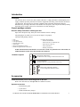
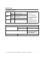
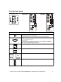
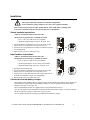
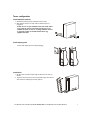
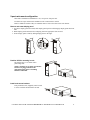
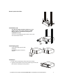
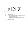
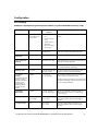
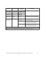
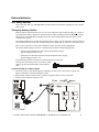
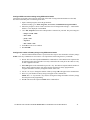
Smart-UPS® RC
Uninterruptible Power Supply
Tower/Rack-Mount 4U
UXI/UXICH
SRC1000/2000/3000 VA
220/230/240 Vac
English
990-3468A
09/2011
Introduction
Overview
The American Power Conversion (APC®) Smart-UPS® RC is a high performance uninterruptible power
supply (UPS) that provides protection for electronic equipment from utility power blackouts, brownouts,
sags and surges. The UPS protects electronic equipment from small utility fluctuations and large
disturbances by providing continuous on-line double converted power. The UPS provides battery backup
until utility power returns to safe levels or the batteries are fully discharged.
Unpack package contents
Read the Safety Guide before installing the UPS.
Inspect the UPS upon receipt. Notify the carrier and dealer if there is damage.
The packaging is recyclable; save it for reuse or dispose of it properly.
Check the UPS package contents:
•
•
•
•
•
•
•
UPS
Front bezel
Front panel display
External battery cable
Serial cable
Rack-mount/stabilizer brackets
Hardware supplied listed in table below
• Literature kit containing:
– Product documentation
– Smart-UPS® RC User Manuals CD
– PowerChute® Utility CD
– Safety information
– Warranty information
NOTE: The model and serial numbers are located on a small, rear panel label. For some models, an
additional label is located on the chassis under the front bezel.
Hardware supplied
8
Rack-mount configuration:
Pan head screws for securing rack-mount brackets to unit
2
Tower configuration:
Flat head screws for securing stabilizer brackets unit
Rack-mount configuration brackets
Tower configuration stabilizer brackets
su0211b
2
Accessories
Install accessories prior to connecting power to the UPS.
Refer to the APC Web site, www.apc.com for available accessories.
Optional accessories
• External battery pack
• 4-post rail kit
• 600 W internal battery charger
User Manual Smart-UPS RC UXI/UXICH 1000/2000/3000 VA 220/230/240 Vac Tower/Rack-Mount 4U
3
Specifications
Environmental Specifications
Temperature
Maximum
Elevation
Operating
0° to 40° C (32° to 104° F)
Storage
-15° to 45° C (5° to 113° F)
Operating
3,000 m (10,000 ft)
Storage
15,000 m (50,000 ft)
Humidity
0 to 95% relative humidity, non-condensing
This unit is intended for indoor use
only. Select a location sturdy enough to
handle the weight.
Do not operate UPS where there is
excessive dust or temperature or
humidity are outside specified limits.
Be sure air vents on UPS are not
blocked. Allow adequate space for
proper ventilation.
Environmental factors impact battery
life. High temperatures, poor utility
power, and frequent, short duration
discharges will shorten battery life.
Physical Specifications
Weight - Refer to Safety Guide supplied with this unit for lifting guidelines.
UPS model
1000 VA
2000/3000 VA
14 kg
31 lbs
16 kg
36 lbs
Maximum number of XLBPs supported by Smart-UPS RC
Dimensions - Length x Width x Height
10
Combined weights of UPS and all
XLBPs installed in a rack must not
exceed rack weight limits.
46 cm (18 in) x 43 cm (17 in) x 18 cm (7 in)
User Manual Smart-UPS RC UXI/UXICH 1000/2000/3000 VA 220/230/240 Vac Tower/Rack-Mount 4U
4
Front and rear panels
UXI Model
Rear Panel
su0314a
su0313a
Test
UXICH Model
Rear Panel
su0311a
Front Display Panel
Rear panel Features
SRC1000UXICH model has one input circuit breaker.
Other models have two input circuit breakers.
The input circuit breakers protect the UPS from extreme overload conditions.
Serial port for:
• Power management software
• Interface kits
Use only interface kits supplied or approved by APC. Any other serial interface
cable will be incompatible with UPS connector.
The UPS is equipped with surge protected Network In and Network Out connectors.
Emergency Power Off (EPO) terminal allows user to connect UPS to central EPO system.
Covers for output and input hardwire terminal blocks.
Output
Input
External battery pack connector
User Manual Smart-UPS RC UXI/UXICH 1000/2000/3000 VA 220/230/240 Vac Tower/Rack-Mount 4U
5
Installation
Units may vary in appearance from those depicted in this manual.
Always place UPS above XLBPs in rack-mount configuration.
Connect all battery strings. Failure to do so may cause equipment damage.
Refer to Physical Specifications in this manual and the Safety Guide before installing units.
Unit is heavy. Batteries must be removed from unit prior to installation
Output hardwire instructions
Adhere to all national and local electrical codes.
Wiring must be performed by a qualified electrician.
• Use 1.3 mm2 (#16 AWG) wire (not supplied)
1. Locate the hardwire terminal block cover on rear panel of UPS.
Remove the screw securing the cover and remove cover.
2. Connect wires to terminal block. Terminals are labelled for proper
wire configuration.
3. Replace and secure cover removed in step 1.
Input hardwire instructions
su0317a
• Maximum output rating: 220-240 V, 50-60 Hz, 10 A
Adhere to all national and local electrical codes.
Wiring must be performed by a qualified electrician.
• Use 3.3 mm2 (#12 AWG) wire (not supplied)
• Install a high magnetic 30/32 A utility circuit breaker
su0318a
• Maximum input rating: 220-240 V, 50-60 Hz, 25 A
1. Switch the circuit breaker OFF.
2. Locate the hardwire terminal block cover on rear panel of UPS.
Remove the screw securing the cover and remove cover.
3. Connect wires to terminal block and secure using torque 16 lb-in.
Terminals are labelled for proper wire configuration.
4. Replace and secure cover removed in step 2.
Connect the internal battery charger
2000/3000 VA UXI/UXICH models are equipped with a 600 W internal battery charger. These models can
accommodate an optional 600 W internal battery charger. To order an optional 600 W internal battery
charger contact APC at www.apc.com.
1000 VA UXI/UXICH models are equipped with a 250 W internal battery charger.
1000 VA UXI models can accommodate an optional 600 W internal battery charger. To order an optional
600 W internal battery charger contact APC at www.apc.com.
1000 VA UXICH models do not support an additional internal battery charger.
User Manual Smart-UPS RC UXI/UXICH 1000/2000/3000 VA 220/230/240 Vac Tower/Rack-Mount 4U
6
Install stabilizer brackets
1. Stabilizer brackets must be installed on tower units.
2. Each bracket must be secured with two flat head screws
(supplied).
NOTE: Screws are pre-installed on left side of unit. These
screws must be removed from unit and used to secure
stabilizer bracket. Screws for securing stabilizer bracket
to right side of unit are included in hardware bag
supplied with unit.
su212a
Tower configuration
s u0 2 28 a
Install display panel
Locate UPS display panel in UPS packaging.
su0244a
Install bezel
1. Fit three tabs on bottom inside edge of the bezel into slots in
chassis.
2. Tip bezel forward. Fit two tabs on top inside edge of bezel into
slots in chassis and snap bezel into position.
User Manual Smart-UPS RC UXI/UXICH 1000/2000/3000 VA 220/230/240 Vac Tower/Rack-Mount 4U
7
2-post rack-mount configuration
This UPS is intended for installation in a 19”, two-post or four-post rack.
For details on 4-post rail and rack installation refer to instructions in rail kit.
Remove stabilizer brackets if they are installed. Remove four screws that secure each bracket.
su0245a
Remove and rotate display panel
1. To remove display panel from UPS, slide display panel up.This will disengage display panel tabs from
UPS.
2. Rotate display panel and insert tabs on display panel into appropriate slots on UPS.
3. Secure display panel to UPS by sliding display panel to the right.
Position UPS for mounting in rack
The UPS is heavy. Use caution when
positioning UPS.
NOTE: The holes for securing rack-mount
brackets are plugged. Remove the
appropriate plugs prior to installing
brackets on the unit.
su02
46 a
x8
x4
su0274b
Install rack-mount brackets
Four pan head screws (supplied), must be used
to secure each rack-mount bracket to UPS.
x4
User Manual Smart-UPS RC UXI/UXICH 1000/2000/3000 VA 220/230/240 Vac Tower/Rack-Mount 4U
8
su0248a
Secure 2-post rack to floor
Install UPS in rack
The UPS and XLBPs should be installed at or near
bottom of rack. Always place UPS above XLBPs.
Batteries must be removed from units prior to
installation in a rack.
Two screws (not supplied), must be used to secure each
rack-mount bracket to rack.
su0249a
x2
x2
Install display panel
Locate UPS display panel in UPS
packaging.
su0250a
Install display panel as shown in
diagram.
User Manual Smart-UPS RC UXI/UXICH 1000/2000/3000 VA 220/230/240 Vac Tower/Rack-Mount 4U
su0241a
Install bezel
1. Fit three tabs on inside edge of bezel into slots in chassis.
2. Tip bezel toward chassis. Fit two tabs on inside edge of bezel into
slots in chassis and snap bezel into position.
9
Start-up
Connect equipment and external battery packs to UPS
Prior to connecting the grounding cable, ensure that the UPS is NOT connected to
utility or battery power.
1. Connect equipment to UPS (cables not supplied). Avoid using extension cords.
2. External battery packs provide extended runtime during power outages. This unit supports up to ten
external battery packs. Refer to the APC Web site, www.apc.com for information. Refer to the user manual
for the external battery pack for installation instructions.
3. Switch the circuit breaker ON.
4. To use UPS as a master on/off switch be sure all connected equipment is switched on. Equipment will not
receive power until UPS is turned on.
5. Configure Network Management card (NMC). Refer to NMC documentation for instructions.
Start the UPS
The charge time for external batteries will vary depending on the number of batteries connected to the
UPS. Refer to the APC Web site, www.apc.com for APC battery runtimes.
Press the TEST button located on the front panel of UPS.
User Manual Smart-UPS RC UXI/UXICH 1000/2000/3000 VA 220/230/240 Vac Tower/Rack-Mount 4U
10
Operation
Front panel display
Load
Test
su0311a
Battery Charge
Display panel function buttons and indicators
UPS function buttons
Button
Test
Function
This button has three functions.
• Press this button to turn on the UPS.
• Press this button to initiate a Cold Start. Cold Start is not a normal condition. When there is no
utility power and UPS is off, press and hold this button to restore power to UPS. UPS will emit
two beeps. During second beep, release the button.
• Press this button to initiate a Self-Test.
Automatic: The UPS performs a self-test automatically when turned on, and every two weeks
there after by default. During self-test, UPS briefly operates on battery power.
Manual: Press and hold Test button for a few seconds to initiate self-test.
This button is used to switch UPS off.
User Manual Smart-UPS RC UXI/UXICH 1000/2000/3000 VA 220/230/240 Vac Tower/Rack-Mount 4U
11
UPS indicators
Indicator
Description
On Line
The On Line LED illuminates when UPS is drawing utility power and performing double conversion
to supply power to connected equipment.
On Battery
Bypass
Fault
The UPS is supplying battery power to connected equipment.
The Bypass LED illuminates indicating that UPS is in bypass mode. Utility power is sent directly to
connected equipment during bypass mode operation. Bypass mode operation is the result of an
internal UPS fault or an overload condition. Refer to Troubleshooting in this manual.
Battery operation is not available while UPS is in bypass mode.
The UPS detects an internal fault. Refer to Troubleshooting in this manual.
X
Overload
An overload condition exists.Refer to Troubleshooting in this manual.
Battery
Fault
The battery is disconnected or must be replaced. Refer to Troubleshooting in this manual.
230V
The UPS has a diagnostic feature that indicates utility voltage.
The UPS starts a self-test as part of this procedure. The self-test does not affect voltage display.
Press and hold the Test button to view utility voltage bar graph indicator. As soon as the On Line
LED starts flashing indicating a self-test is in progress, the five-LED Battery Charge indicator to
the right of the display panel will show utility input voltage.
Refer to diagram for voltage reading.
Values are not listed on the UPS.
Indicator on UPS shows voltage is between displayed value on list and the next higher value, Refer
to Troubleshooting in this manual for more details.
User Manual Smart-UPS RC UXI/UXICH 1000/2000/3000 VA 220/230/240 Vac Tower/Rack-Mount 4U
12
Configuration
UPS Settings
Settings are adjusted through PowerChute software or optional SmartSlot accessory cards.
Function
Factory Default
User Selectable
Choices
• Every 7 days (168
hr)
• On start-up and
every
14 days (336 hr)
there after
• On start-up only
• No self-test
Description
Automatic Self-Test
On start-up and
every 14 days (336
hr) there after
UPS ID
UPS_IDEN
Up to 8 characters
(alphanumeric)
Uniquely identify UPS, (i.e. server name or
location) for network management purposes.
Date of last battery
replacement
Manufacture date
mm/dd/yy
Reset date when you replace the battery module.
Minimum capacity
before return from
shutdown
0%
0%, 15%, 25%, 35%,
50%, 60%, 75%, 90%
Specify percentage to which batteries will be
charged following a low battery shutdown before
powering connected equipment.
Set the interval at which the UPS will execute a
self-test.
Alarm delay control Enable
Enable, Mute, Disable
Shutdown delay
0, 20, 60, 120, 240, 480, Set interval between time when UPS receives a
720, 960 seconds
shutdown command and actual shutdown.
20 seconds
• Mute ongoing alarms.
• Disable all alarms permanently.
Low battery
2 minutes
warning
PowerChute software
interface provides
automatic, unattended
shutdown when
approximately two
minutes of battery
operated run time
remains.
2, 5, 7, 10, 12,
15, 18, 20 minutes
Synchronize
turn-on delay
0 seconds
0, 20, 60, 120, 240,
480, 720, 960 seconds
Specify time UPS will wait after the return of
utility power before start up, to avoid branch
circuit overload.
High bypass point
+10% of
output voltage
+5%, +10%,
+15%, +20%
Maximum voltage that UPS will pass to
connected equipment during internal bypass
operation.
Low bypass point
-30%
-15%, -20%,
-25%, -30%
Minimum voltage that the UPS will pass to
connected equipment during internal bypass
operation.
The low-battery warning beeps are continuous
when two minutes of run time remain.
Change low battery warning interval setting to the
time that the operating system or system software
requires to safely shut down.
User Manual Smart-UPS RC UXI/UXICH 1000/2000/3000 VA 220/230/240 Vac Tower/Rack-Mount 4U
13
Function
Factory Default
User Selectable
Choices
Output voltage
Description
Allows user to select output voltage while on-line.
220 V models
220 Vac
200, 208, 220,
230, 240 Vac
230 V models
230 Vac
200, 208, 220,
230, 240 Vac
Output frequency
Automatic
50 ± 3 Hz
60 ± 3 Hz
Automatic
50 ± 3 Hz, 50 ± 0.1 Hz,
60 ± 3 Hz, 60 ± 0.1 Hz
Sets allowable UPS output frequency. Whenever
possible, output frequency tracks input frequency.
Number of
battery strings
1
Number of connected
battery strings
Defines number of connected battery strings for
proper run time prediction.
1000/2000 VA models
default setting of 1=432 VAh, 96 V x 4.5 Ah
Refer to XLBP user manual for details on
configuring UPS and # of battery strings.
3000 VA models
default setting of 1=691 VAh, 96 V x 7.2 Ah
Refer to XLBP user manual for details on
configuring UPS and # of battery strings.
Configuration for a third party battery solution
Examples: 1 battery string = 691 VAh, 96 V x 7.2 Ah; 2 battery strings = 1382 VAh, 96 V x 14.4 Ah
User Manual Smart-UPS RC UXI/UXICH 1000/2000/3000 VA 220/230/240 Vac Tower/Rack-Mount 4U
14
Emergency Power Off (EPO)
The Emergency Power Off (EPO) option is a safety feature that will immediately remove power to all
connected equipment. When EPO button is pushed, all connected equipment will immediately turn off and
will not switch to battery power.
Adhere to all national and local electrical codes. Wiring must be performed by a qualified electrician.
The switch should be connected in a normally open switch contact. External voltage is not required; the
switch is driven by 12 V internal supply. In closed condition, 2 mA of current are drawn.
The EPO switch is internally powered by the UPS for use with non-powered switch circuit breakers.
Connect the EPO
The EPO connector is located on the rear panel of the UPS.
1. Strip insulation from one end of each wire to be used for connecting EPO.
2. Insert a screwdriver into the slot above the terminal to be wired. Insert stripped wire into
terminal. Remove screwdriver to secure wire in terminal. Repeat for each terminal.
The EPO interface is a Safety Extra Low Voltage (SELV) circuit. Connect it only to other SELV
circuits. The EPO interface monitors circuits that have no determined voltage potential. Such
closure circuits may be provided by a switch or relay properly isolated from the utility. To avoid
damage to the UPS, do not connect the EPO interface to any circuit other than a closure type circuit.
Use one of the following cable types to connect the UPS to the EPO switch.
• CL2: Class 2 cable for general use.
• CL2P: Plenum cable for use in ducts, plenums, and other spaces used for environmental air.
• CL2R: Riser cable for use in a vertical run in a floor-to-floor shaft.
• CLEX: Limited use cable for use in dwellings and for use in raceways.
• For installation in Canada: Use only CSA certified, type ELC, (extra-low voltage control cable).
• For installation in other countries: Use standard low-voltage cable in accordance with national and
local regulations.
User Manual Smart-UPS RC UXI/UXICH 1000/2000/3000 VA 220/230/240 Vac Tower/Rack-Mount 4U
15
External batteries
APC battery solution
Refer to the APC Web site, www.apc.com or an APC dealer for information regarding the APC external
battery pack.
Third party battery solution
Batteries must be sealed lead-acid type. Use 50 A, 250 VDC fuses with an interrupt rating of > 20,000 A.
The UPS internal battery chargers are optimized only for VRLA/AGM type batteries. Do not exceed the
maximum recommended battery charging current rate when configuring the amp-hour capacity of the
external battery system.
The UPS is intended for use with 96 VDC nominal battery voltage. The external battery system connected
to the UPS must not exceed 96 VDC nominal voltage. This equals eight 12 V batteries connected in series.
Refer to the Configuration section in this manual for details on battery string configuration.
The internal battery chargers operate in a constant current/constant voltage charging mode.
• 1000 VA UXI/UXICH models with 250 W internal battery charger:
Typical charging current is 2.2 A.
• 2000/3000 VA UXI/UXICH models with 600 W internal battery charger:
Typical charging current is 5 A.
External batteries must be wired prior to connecting batteries to the UPS.
If using a non-APC battery pack, a 96 V battery string
must be wired to the UPS using the enclosed battery
cable.
Connect the UPS to a battery system
1. Connect the positive (red), ground (green), and negative (black), wires to the positive, ground, and
negative terminals on each external battery system.
2. Plug the cable connector into the battery connector receptacle on the rear side of the UPS.
3. Secure the cable connector with one screw.
Fuse:
96 V
su0302a
96 V
User Manual Smart-UPS RC UXI/UXICH 1000/2000/3000 VA 220/230/240 Vac Tower/Rack-Mount 4U
16
Configure UPS parameters
This configuration affects the accuracy of the predicted runtime calculations the UPS performs
while running on battery power.
Refer to the Battery String Configuration tables at the end of this section for detailed instructions.
Smart-UPS RC models must be programed to recognize the number of battery strings connected to the UPS.
There are four options available for configuring the UPS to recognize the number of battery strings
1. PowerChute® Business Edition: Refer to the instructions included with the software
2. Network Management Card (NMC) Web interface: Refer to the instructions included with NMC
3. Network Management Card (NMC) terminal mode: Refer to the instructions below
4. UPS terminal mode
Configure UPS connection settings using NMC terminal mode
Connect the serial cable to the serial com port on rear side of UPS.
1. Open a terminal program, such as HyperTerminal®.
From the Desktop, go to: Start, Programs, Accessories, Communication, HyperTerminal
2. Follow the prompts to choose a name and select an icon. If the message, "...must install a
modem," click Cancel.
3. Go to File, Properties. Select the COM port that is connected to your UPS. The port settings are:
– bits per second - 2400
– data - bits 8
– parity - none
– stop bit - 1
– flow control - none
4. Click OK in each of two windows
5. Press ENTER to initiate connection to UPS.
User Manual Smart-UPS RC UXI/UXICH 1000/2000/3000 VA 220/230/240 Vac Tower/Rack-Mount 4U
17
Configure the number of battery strings using NMC terminal mode
1. Once the blank terminal window is open:
2. Press ENTER to initiate terminal mode. Press ENTER multiple times, until the prompt
User Name: is displayed. Follow the prompts. Type slowly, waiting until each character appears
on the screen prior to typing the next character.
Network Management Card defaults:
• User Name: apc
• Password: apc
3. Press 1 and ENTER to select Device Manager.
Select the model by entering the corresponding number, then press ENTER.
4. Press 3 and ENTER to select Configuration.
5. Press 1 and ENTER to select Battery.
6. Press 2 and ENTER to change Battery Settings.
7. Type in the number of battery strings then press ENTER.
8. Press 3 and ENTER to accept the changes.
9. Press ESC five times to return to the main menu.
10. Press 4 and ENTER to log out.
User Manual Smart-UPS RC UXI/UXICH 1000/2000/3000 VA 220/230/240 Vac Tower/Rack-Mount 4U
18
Configure UPS connection settings using UPS terminal mode
Connect the serial cable to the serial port on the back of the UPS. If using USB communication to the UPS,
disconnect USB cable prior to connecting serial cable.
1. Open a terminal program, such as HyperTerminal
From the Desktop, go to: Start, Programs, Accessories, Communication, HyperTerminal
2. Follow the prompts to choose a name and select an icon. Disregard the message, "...must install a
modem," if it is displayed. Click Cancel
3. Go to File, Properties. Select the COM port that is connected to your UPS. The port settings are:
– bits per second - 2400
– data - bits 8
– parity - none
– stop bit - 1
– flow control - none
4. Click OK in each of two windows
5. Press ENTER
Configure the number of battery strings using UPS terminal mode
1. Once the blank terminal window is open, follow these steps to enter the number of battery strings:
NOTE: Letter key commands are case sensitive. Use capital letters when using letter key commands.
2. Press Y. The UPS will respond with SM in the command box. If the UPS does not respond to the
Y command, ensure the serial cable is securely connected to the serial port on the UPS. Use only
an APC supplied serial cable.
3. When SM appears in the command box press the > key. The UPS will respond with the number of
battery strings connected to the UPS. If the UPS has not been previously programmed to
recognize the number of battery strings this number will be zero.
4. Use the + or - keys to change the number of battery strings. OK will appear in the command box.
5. Press > key. The number of battery strings will appear in the command box.
NOTE: The + or - keys and the > key must be used again to change the number of battery strings
from this point in the programming.
6. Press R. The UPS will respond with BYE in the command box.
User Manual Smart-UPS RC UXI/UXICH 1000/2000/3000 VA 220/230/240 Vac Tower/Rack-Mount 4U
19
Troubleshooting
Use the table below to solve minor installation and operation problems. Refer to the APC Web site,
www.apc.com for assistance with complex UPS problems.
Problem and/or Possible Cause
Solution
UPS will not turn on
The battery is not connected properly.
Check that the battery connector is fully engaged.
Test button not pushed.
Press the Test button once to power-up the UPS and connected equipment.
The UPS is not connected to utility
power supply.
Check that the power cable from the UPS to the utility power supply is
securely connected at both ends.
Very low or no utility voltage.
Check utility power supply to UPS by plugging in a table lamp. If light is
very dim, have utility voltage checked.
UPS will not turn off
The UPS is experiencing an internal fault.
Do not attempt to use UPS. Unplug UPS and have it serviced immediately.
UPS beeps occasionally
Normal UPS operation when running on
battery.
None: UPS is protecting connected equipment.
Press the Test button to silence this alarm.
UPS is not providing expected backup time
The UPS battery(s) are weak due to a recent
power outage or battery(s) are near the end
of their service life.
Charge the battery(s). Batteries require recharging after extended outages.
Batteries can wear faster when put into service often or when operated at
elevated temperatures. If the battery(s) are near the end of their service life,
consider replacing the battery(s) even if the Battery Fault LED is not yet
illuminated.
Front panel LEDs flash sequentially
The UPS has been shut down remotely
through software or an optional accessory
card.
None: UPS will restart automatically when utility power returns.
All LEDs are off and the UPS is plugged into a wall outlet
The UPS is shut down or the battery is
discharged from an extended outage.
None: UPS will restart automatically when utility power is restored and
battery has a sufficient charge.
The Bypass and Overload LEDs are illuminated and the UPS emits a sustained alarm tone
The UPS is overloaded.
Connected equipment exceeds specified “maximum load” as defined in
Specifications on APC Web site, www.apc.com.
The alarm remains on until overload is removed. Disconnect nonessential
equipment from UPS to eliminate overload condition.
The UPS continues to supply power as long as it is on line and circuit
breaker does not trip; UPS will not provide power from batteries in the event
of a utility voltage interruption.
Fault LED is illuminated
Internal UPS fault.
Do Not attempt to use UPS. Turn UPS off and have it serviced immediately.
Refer to APC Web site, www.apc.com.
User Manual Smart-UPS RC UXI/UXICH 1000/2000/3000 VA 220/230/240 Vac Tower/Rack-Mount 4U
20
Problem and/or Possible Cause
Solution
Bypass and Fault LEDs are illuminated
The UPS has automatically switched to
In the event an internal UPS fault occurs, Do Not attempt to use UPS. Turn
Bypass mode. Bypass mode operation is the UPS off and have it serviced immediately. Refer to APC Web site,
result of an internal UPS fault or an overload www.apc.com.
condition while operating on utility power.
Battery fault (Disconnected Battery/ Replace Battery) LED is illuminated
The Disconnected Battery/Replace Battery Check that the battery connectors are fully engaged.
LED flashes and a short beep is emitted every
two seconds to indicate the battery is
disconnected.
Weak battery.
Allow battery to recharge for 24 hours and perform a self-test. If the
problem persists after recharging, replace battery.
Failure of a battery self-test: Disconnected
Battery/
Replace Battery LED illuminates and the
UPS emits short beeps for one minute. The
UPS repeats the alarm every five hours.
Allow battery to recharge for 24 hours. Perform the self-test procedure to
confirm the replace battery condition. The alarm stops and the LED clears if
the battery passes the self-test.
If battery fails again, it must be replaced. The connected equipment is
unaffected.
Input circuit breaker trips
The connected equipment exceeds the
specified “maximum load” as defined in
Specifications on the APC Web site,
www.apc.com.
Unplug all nonessential equipment from UPS.
Reset circuit breaker.
There is no utility power
There is no utility power and the UPS is off.
120/230 V models only: Use cold start feature to supply power to connected
equipment from UPS battery(s).
Press and hold the Test button. There will be a short beep followed by a
longer beep. Release the button during second beep.
UPS operates on battery although line voltage exists
The UPS input circuit breaker trips.
Unplug all nonessential equipment from UPS.
Reset circuit breaker.
Your system is experiencing very high, low
or distorted line voltage.
Move UPS to a different outlet on a different circuit: Inexpensive fuel
powered generators may distort the voltage. Test input voltage with utility
voltage display, (see Operation in this manual). If acceptable to connected
equipment, reduce UPS sensitivity.
Diagnostic utility voltage
All five LEDs are illuminated.
The line voltage is extremely high and should be checked by an electrician.
There is no LED illumination.
The line voltage is extremely low and should be checked by an electrician.
On Line LED
There is no LED illumination.
The UPS is running on battery, or it must be turned on.
The LED is blinking.
The UPS is running an internal self-test.
User Manual Smart-UPS RC UXI/UXICH 1000/2000/3000 VA 220/230/240 Vac Tower/Rack-Mount 4U
21
Transporting the UPS
Prepare the UPS for transport
1.
2.
3.
4.
Disconnect UPS from any external batteries.
Shut down and disconnect all equipment connected to UPS.
Shut down and disconnect UPS from utility power.
Follow shipping instructions outlined in the Service section of this manual.
Regulatory Agency Approvals and Radio Frequency Warnings
Class A
This device complies with EN62040-2 Class A requirements. Operation is subject to the following two
conditions:
1. This device may not cause harmful interference.
2. This device must accept any interference received, including interference that may cause undesired
operation.
User Manual Smart-UPS RC UXI/UXICH 1000/2000/3000 VA 220/230/240 Vac Tower/Rack-Mount 4U
22
Service
If the UPS requires service do not return it to the dealer. Follow these steps:
1. Review the problems discussed in Troubleshooting in this manual to eliminate common problems.
2. If the problem persists, contact APC Customer Support through the APC Web site, www.apc.com.
a. Note the model number of the UPS, the serial number located on the rear side of the unit,
and the date purchased. If you call APC Customer Support, a technician will ask you to
describe the problem and attempt to solve it over the phone. If this is not possible, the
technician will issue a Returned Material Authorization Number (RMA#).
b. If the UPS is under warranty, repairs are free.
c. Procedures for servicing or returning products may vary internationally. Refer to the APC
Web site for country specific instructions.
3. Pack the UPS in its original packaging. If this is not available, refer to www.apc.com for information about
obtaining a new set.
a. Pack the UPS properly to avoid damage in transit. Never use Styrofoam beads for
packaging. Damage sustained in transit is not covered under warranty.
b. Always DISCONNECT THE UPS BATTERY before shipping in compliance with U.S.
Department of Transportation (DOT) and IATA regulations. The battery may remain in
the UPS.
4. Mark the RMA# on the outside of the package.
5. Return the UPS by insured, prepaid carrier to the address given to you by Customer Support.
Contact Information
APC Worldwide Customer Support
Customer support for this or any other APC product is available at no charge in any of the following ways:
• Refer to the APC Web site to access documents in the APC Knowledge Base and to submit
customer support requests.
–
www.apc.com (Corporate Headquarters)
Connect to localized APC Web sites for specific countries, each of which provides customer
support information.
– www.apc.com
Global support searching APC Knowledge Base and using e-support.
• Contact an APC Customer Support center by telephone or e-mail.
Local, country-specific centers:
go to www.apc.com for information.
Contact the APC representative or other distributor from whom you purchased your APC product for
information on how to obtain local customer support.
User Manual Smart-UPS RC UXI/UXICH 1000/2000/3000 VA 220/230/240 Vac Tower/Rack-Mount 4U
23
Two-Year Warranty
The limited warranty provided by American Power Conversion (APC®) in this statement of Limited Factory Warranty applies only to
products you purchase for your commercial or industrial use in the ordinary course of your business.
Terms of warranty
APC warrants its products to be free from defects in materials and workmanship for a period of two years from the date of purchase. The
obligation of APC under this warranty is limited to repairing or replacing, at its sole discretion, any such defective products. This warranty
does not apply to equipment that has been damaged by accident, negligence or misapplication or has been altered or modified in any way.
Repair or replacement of a defective product or part thereof does not extend the original warranty period. Any parts furnished under this
warranty may be new or factory-remanufactured.
Non-transferable warranty
This warranty extends only to the original purchaser who must have properly registered the product. The product may be registered at the
APC Web site, www.apc.com.
Exclusions
APC shall not be liable under the warranty if its testing and examination disclose that the alleged defect in the product does not exist or was
caused by end user or any third person misuse, negligence, improper installation or testing. Further, APC shall not be liable under the
warranty for unauthorized attempts to repair or modify wrong or inadequate electrical voltage or connection, inappropriate on-site operation
conditions, corrosive atmosphere, repair, installation, start-up by non-APC designated personnel, a change in location or operating use,
exposure to the elements, Acts of God, fire, theft, or installation contrary to APC recommendations or specifications or in any event if the
APC serial number has been altered, defaced, or removed, or any other cause beyond the range of the intended use.
THERE ARE NO WARRANTIES, EXPRESS OR IMPLIED, BY OPERATION OF LAW OR OTHERWISE, OF PRODUCTS SOLD,
SERVICED OR FURNISHED UNDER THIS AGREEMENT OR IN CONNECTION HEREWITH. APC DISCLAIMS ALL IMPLIED
WARRANTIES OF MERCHANTABILITY, SATISFACTION AND FITNESS FOR A PARTICULAR PURPOSE. APC EXPRESS
WARRANTIES WILL NOT BE ENLARGED, DIMINISHED, OR AFFECTED BY AND NO OBLIGATION OR LIABILITY WILL
ARISE OUT OF, APC RENDERING OF TECHNICAL OR OTHER ADVICE OR SERVICE IN CONNECTION WITH THE PRODUCTS.
THE FOREGOING WARRANTIES AND REMEDIES ARE EXCLUSIVE AND IN LIEU OF ALL OTHER WARRANTIES AND
REMEDIES. THE WARRANTIES SET FORTH ABOVE CONSTITUTE APC SOLE LIABILITY AND PURCHASER EXCLUSIVE
REMEDY FOR ANY BREACH OF SUCH WARRANTIES. APC WARRANTIES EXTEND ONLY TO PURCHASER AND ARE NOT
EXTENDED TO ANY THIRD PARTIES.
IN NO EVENT SHALL APC, ITS OFFICERS, DIRECTORS, AFFILIATES OR EMPLOYEES BE LIABLE FOR ANY FORM OF
INDIRECT, SPECIAL, CONSEQUENTIAL OR PUNITIVE DAMAGES, ARISING OUT OF THE USE, SERVICE OR INSTALLATION,
OF THE PRODUCTS, WHETHER SUCH DAMAGES ARISE IN CONTRACT OR TORT, IRRESPECTIVE OF FAULT, NEGLIGENCE
OR STRICT LIABILITY OR WHETHER APC HAS BEEN ADVISED IN ADVANCE OF THE POSSIBILITY OF SUCH DAMAGES.
SPECIFICALLY, APC IS NOT LIABLE FOR ANY COSTS, SUCH AS LOST PROFITS OR REVENUE, LOSS OF EQUIPMENT, LOSS
OF USE OF EQUIPMENT, LOSS OF SOFTWARE, LOSS OF DATA, COSTS OF SUBSTITUENTS, CLAIMS BY THIRD PARTIES, OR
OTHERWISE.
NO SALESMAN, EMPLOYEE OR AGENT OF APC IS AUTHORIZED TO ADD TO OR VARY THE TERMS OF THIS WARRANTY.
WARRANTY TERMS MAY BE MODIFIED, IF AT ALL, ONLY IN WRITING SIGNED BY AN APC OFFICER AND LEGAL
DEPARTMENT.
Warranty claims
Customers with warranty claims issues may access the APC customer support network through the Support page of the APC Web site,
www.apc.com. Select your country from the country selection pull-down menu. Open the Support tab at the top of the Web page to obtain
contact information for customer support in your region.
Entire contents copyright 2009 American Power Conversion Corporation. All rights reserved. Reproduction in whole or in part
without permission is prohibited.
APC, the APC logo, Smart-UPS and PowerChute are trademarks of American Power Conversion Corporation. All other trademarks,
product names, and corporate names are the property of their respective owners and are used for informational purposes only.
User Manual Smart-UPS RC UXI/UXICH 1000/2000/3000 VA 220/230/240 Vac Tower/Rack-Mount 4U
24