1
The MIT Sensor Robot:
User's Guide and Technical Reference
Fred Martin
October 22, 1991
Preface
The MIT Sensor Robot is a small, mobile robot designed for educational and
experimental use. Its intelligence is based on a Motorola 6811 microprocessor
with 32K of battery-backed memory.
The Sensor Robot was designed for maximal features while retaining a
fundamentally simple design: most of the robot's sensors are soldered directly
onto its single circuit board. Thus the robot has minimal connectors and is
easy to construct.
The Sensor Robot is so named because it has a multitude of common
robotic sensors: touch bumpers, ambient light and light direction sensing,
infrared obstacle detection sensing, wheel velocity sensing, inclination sensing, and others. Optional features include a low-powered transmit/receive
radio network for inter-robot communication.
The robot's single circuit board is mounted with standos on an aluminum frame. Underneath the chassis are the robot's mechanics and battery. The robot uses a dual geared-wheel drive that was borrowed from an
inexpensive Radio Shack car for locomotion. Its power source is a small,
rechargeable 6v battery.
The Sensor Robot runs the multi-tasking Interactive C software system
that was developed for the MIT Robot Design Competition. This system
consists of a C compiler (running on a host PC, Mac, or Unix machine) and
an interpreter (running on the robot). The C compiler compiles C programs
and dynamically entered expressions, and downloads them to the robot for
evaluation. Thus the system gives to the user the appearance of an interactive
C interpreter. The interpreter module, written in 6811 machine code, runs
on the robot at all times and is capable of multi-tasking up to 32 concurrent
C processes.
It is hoped that the Sensor Robot and the Interactive C software system
make for a powerful yet simple to use robot development kit, which will allow
students to explore ideas in robotics in a concrete, project-oriented way, and
researchers to easily conduct experiments with real mobile robots.
The Sensor Robot was designed by Fred Martin, based on the 6.270 Revision 2 Robot Controller Board created by Fred Martin and Randy Sargent.
The Interactive C software environment was designed and implemented
by Randy Sargent with the assistance of Fred Martin.
i
Contents
1 User's Guide
1.1 Overview : : : : : : : : : : : : : : : : : : : :
1.1.1 Sensors : : : : : : : : : : : : : : : : :
1.1.2 Other Input and Output : : : : : : :
1.1.3 Motor Control : : : : : : : : : : : : :
1.1.4 Radio Link : : : : : : : : : : : : : :
1.2 Sensors : : : : : : : : : : : : : : : : : : : : :
1.2.1 Photocell Sensors : : : : : : : : : : :
1.2.2 Whisker Sensors : : : : : : : : : : : :
1.2.3 Touch Sensors : : : : : : : : : : : : :
1.2.4 Inclination Sensor : : : : : : : : : : :
1.2.5 Pyroelectric Sensor : : : : : : : : : :
1.2.6 Microphone : : : : : : : : : : : : : :
1.2.7 Floor Reectance Sensors : : : : : :
1.2.8 Shaft Encoders : : : : : : : : : : : :
1.2.9 Infrared Obstacle Detection Sensors :
1.2.10 Infrared Transmission Feedback : : :
1.2.11 Battery Level Sensor : : : : : : : : :
1.3 Other Input and Output : : : : : : : : : : :
1.3.1 Battery Charging : : : : : : : : : : :
1.3.2 Using the Speaker : : : : : : : : : : :
1.3.3 Frob Inputs : : : : : : : : : : : : : :
1.3.4 DIP Conguration Switches : : : : :
1.4 Motor Control : : : : : : : : : : : : : : : : :
1.4.1 Direct Motor Control : : : : : : : : :
1.4.2 Robot-Level Motor Control : : : : :
1.4.3 Motor Velocity Control : : : : : : : :
A C Library Function Handy Reference
B Electrical Assembly Guide
:
:
:
:
:
:
:
:
:
:
:
:
:
:
:
:
:
:
:
:
:
:
:
:
:
:
:
:
:
:
:
:
:
:
:
:
:
:
:
:
:
:
:
:
:
:
:
:
:
:
:
:
B.1 Conventions : : : : : : : : : : : : : : : : : : : :
B.1.1 Component Polarity : : : : : : : : : : :
B.1.2 Flat Mounting versus Upright Mounting
B.2 Assembling the Board : : : : : : : : : : : : : :
ii
:
:
:
:
:
:
:
:
:
:
:
:
:
:
:
:
:
:
:
:
:
:
:
:
:
:
:
:
:
:
:
:
:
:
:
:
:
:
:
:
:
:
:
:
:
:
:
:
:
:
:
:
:
:
:
:
:
:
:
:
:
:
:
:
:
:
:
:
:
:
:
:
:
:
:
:
:
:
:
:
:
:
:
:
:
:
:
:
:
:
:
:
:
:
:
:
:
:
:
:
:
:
:
:
:
:
:
:
:
:
:
:
:
:
:
:
:
:
:
:
:
:
:
:
:
:
:
:
:
:
:
:
:
:
:
:
:
:
:
:
:
:
:
:
:
:
:
:
:
:
:
:
:
:
:
:
:
:
:
:
:
:
:
:
:
:
:
:
:
:
:
:
:
:
:
:
:
:
:
:
:
:
:
:
:
:
:
:
:
:
:
:
:
:
:
:
:
:
:
:
:
:
:
:
:
:
:
:
:
:
:
:
:
:
:
:
:
:
:
:
:
:
:
:
:
:
:
:
:
:
:
:
:
:
:
:
:
:
:
:
2
2
2
4
6
7
7
7
7
8
8
9
9
10
10
12
12
12
12
12
13
13
14
14
14
15
16
18
19
19
19
20
21
B.3 Check-o Parts Listing : : : : : : : :
B.3.1 Integrated Circuit Sockets : :
B.3.2 Resistors : : : : : : : : : : : :
B.3.3 Resistor Packs and Trimpots :
B.3.4 Capacitors : : : : : : : : : : :
B.3.5 Transistors : : : : : : : : : : :
B.3.6 Diodes : : : : : : : : : : : : :
B.3.7 LEDs : : : : : : : : : : : : :
B.3.8 Miscellaneous Components : :
B.3.9 Switches : : : : : : : : : : : :
B.3.10 Integrated Circuits : : : : : :
B.3.11 Sensors : : : : : : : : : : : : :
B.3.12 Connectors : : : : : : : : : :
B.4 Board Parts Layout : : : : : : : : : :
C Mechanical Assembly Guide
:
:
:
:
:
:
:
:
:
:
:
:
:
:
:
:
:
:
:
:
:
:
:
:
:
:
:
:
:
:
:
:
:
:
:
:
:
:
:
:
:
:
:
:
:
:
:
:
:
:
:
:
:
:
:
:
:
:
:
:
:
:
:
:
:
:
:
:
:
:
:
:
:
:
:
:
:
:
:
:
:
:
:
:
:
:
:
:
:
:
:
:
:
:
:
:
:
:
:
:
:
:
:
:
:
:
:
:
:
:
:
:
:
:
:
:
:
:
:
:
:
:
:
:
:
:
:
:
:
:
:
:
:
:
:
:
:
:
:
:
:
:
:
:
:
:
:
:
:
:
:
:
:
:
:
:
:
:
:
:
:
:
:
:
:
:
:
:
:
:
:
:
:
:
:
:
:
:
:
:
:
:
:
:
:
:
:
:
:
:
:
:
:
:
:
:
28
28
28
29
29
29
29
29
30
30
30
30
31
32
33
iii
Introduction
This User's Guide and Technical Reference is organized into two main sections and two appendices.
The rst section is the User's Guide. The section introduces the Sensor
Robot by rst enumerating the various features of the robot, and then explaining how to use each one. The purpose of the User's Guide is to explain
how to use the robot.
The second section is the Technical Reference. This section delves more
deeply into the design of the robot, explaining the architecture of the microprocessor circuit, the ways that various sensors work, and the motor control
circuitry. Reading of this section should not be considered required for those
who simply want to use the robot. The Technical Reference is intended to
provide concrete technical information for educational purposes (for those
who wish to understand better how the robot works) and as hardware documentation.
This manual assumes some familiarity with the Interactive C for the 6811
software environment. The rst appendix section provides a reference for C
library functions that are specic to the Sensor Robot. These functions are
introduced in the User's Guide. A separate document, ic: Multi-tasking Interactive C for the 6811, serves as an introduction and reference to Interactive
C.
The second and third appendix sections provide detailed assembly instructions for the electronics and mechanics of the MIT Sensor Robot.
1
1 User's Guide
The rst part of this section presents an overview of the Sensor Robot's
features. The remainder of the section then discusses each feature in detail.
1.1 Overview
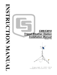
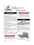
Figures 1 and 2 illustrate the Sensor Robot's circuit board, showing positions
of sensors and other components.
1.1.1 Sensors
Here is a list of the sensors that are used by the Sensor Robot:
Photocells. The robot has three photocells; two are mounted in the front
facing forward to the left and right, and the third is mounted in the
back, facing upward.
Whisker Sensors. A total of eight bend sensitive strips protrude from the
circuit board (arranged in pairs of two). These sensors change resistance when bent, and sense when the robot brushes up against objects.
Touch Sensors. Mounted o-board are four touch sensors. These augment
the sensing capability of the whisker sensors. The touch sensors are
mounted on the left-front, right-front, and back areas of the robot's
body.
Inclination Sensor. Labelled the \tilt sensor" on the diagram, this device
provides inclination data, indicating the tilt of the robot accurate to
one of eight quadrants.
Pyroelectric Sensor. This sensor detects the spectrum of infrared energy
that is typically emitted by mammals|thus, it acts as a \person sensor."
2
3
Back of Robot
Figure 1: Sensor Robot Board Sensors Layout
back right
whisker
sensor
TIL-99
phototransistor
pyroelectric
sensor
Sharp IR
receiver
MLED71
IR xmitter
microphone
back
photocell
MLED71
IR xmitter
MLED71
IR xmitter
back left
whisker
sensor
Sharp IR
receiver
tilt sensor
MLED71
IR xmitter
Sharp IR
receiver
touch sensor connectors
MLED71
IR xmitter
floor and shaft
IR sensor connectors
MLED71
IR xmitter
right front
whisker
sensor
right
photocell
MLED71
IR xmitter
Sharp IR
receiver
left
photocell
left front
whisker
sensor
Front of Robot
Microphone. A single microphone can detect sounds such as particular
tones (generated by other robots) or an abrupt noise (such as a hand
clap).
Shaft Encoders. Shaft encoders monitor the velocity of each of the two
drive axles.
Floor Reectance Sensors. Two infrared reectance sensors determine
the reectivity of the oor underneath the robot. The sensors are
mounted in left-front and right-front positions on the robot chassis.
Infrared Obstacle Detection Sensors. These four sensors (labelled \Sharp
IRs" on the diagram) receive reections of infrared light emitted by the
eight IR emitters (labelled \infrared xmitters" on the diagram).
These sensors can also serve as a primitive inter-robot communication
channel, as robots can see the infrared emissions of other robots.
Infrared Transmission Feedback. A phototransistor aimed at the infrared
transmitters provides feedback data on how bright the modulation of
the transmitters is. This brightness level can be controlled via software.
Battery Level Sensor. Circuitry intrinsic to the board senses the battery
voltage and feeds it back to a microprocessor analog input.
1.1.2 Other Input and Output
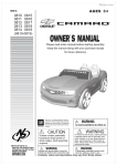
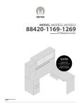
Refer to Figure 2 for location of these connectors, ports, and other devices
mounted on the robot:
On-O Switch. A toggle switch is used to turn the robot on and o. When
the robot is turned o, the system battery provides the small amount
of power necessary to retain the contents of the robot's memory indefinitely.
Reset Button. A red button resets the microprocessor at any time.
Serial Port. A 4-pin modular phone jack provides the connector for a standard RS-232 serial line. This port is used to program the robot from a
host computer.
4
5
Charge Rate
Switch
Battery
Recharging
Jack
Motor
Status
LEDs
Serial Line Jack
Frob
Adjustment
Knob
Ming
RE-99
Connector
6811
LCD Display
System Reset
Charge
Button
Status
DIP Configuration
LEDs System
Switches
Power
Switch
Auxiliary Motor Outputs
User Buttons
LCD Contrast
Knob
Ming
TX-88
Connector
Miniature
Speaker
Element
Low Battery
Serial Transmit
Serial Receive
Infrared Reflectance
Infrared Transmit
System
Status LEDs
Front of Robot
Back of Robot
Figure 2: Sensor Robot Board Connectors Layout
Battery Charge Jack. An AC adapter is plugged into the robot to recharge
its battery.
Battery Charge Rate Switch. A small slide switch selects one of two
charging rates: a normal twelve-hour charge and a three-hour \zap"
charge.
LCD Screen. The robot has a 16 1 character LCD screen for displaying
information to the user.
LCD Contrast Adjustment Knob. A small knob allows contrast adjustment of the LCD screen.
Miniature Speaker. A tiny but loud speaker element provides another
means to provide feedback to humans who may be observing the robot.
Also, the speaker can be used to transmit tones to other robots listening
with their microphone sensors.
Frob Buttons and Knob. Two pushbuttons and a \frob knob" are provided for general-purpose use as interactive input devices. For example, a menuing program may be written to display options on the LCD
screen and allows the user to scroll through and select options.
DIP Conguration Switches. Four DIP switches may be used to select
robot conguration (if several programs or modes are resident in the
robot) or robot ID number (when performing experiments with multiple
robots).
Status Indicator LEDs. A number of LEDs provide specic status information: motor state, battery charge indication, low battery indication,
power on, serial receive, and infrared transmit.
1.1.3 Motor Control
The Sensor Robot has circuitry to bidirectionally control four DC motors.
Two of these motor ports are dedicated to controlling the left and right wheels
of the robot; the other two ports are available for expansion.
Through software, the power level outputted on the motor ports may be
adjusted in eight graduations from o to full on. In the case of the built-in
6
gear drive, the shaft encoders monitoring the wheel speed are used by a servo
routine to implement velocity control.
1.1.4 Radio Link
The Sensor Robot has a built-in interface for the adding of a radio transmit
and receive board set. This board set, manufactured by Ming Electronics1,
provides a four-bit-wide data channel between robots or between robots and
a human.
1.2 Sensors
This section explains in more detail the capabilities of each sensor and how
to use the C library functions associated with it.
1.2.1 Photocell Sensors
Three photocells are built into the Sensor 'Bot. These measure levels of
visible light, being most sensitive to the red spectrum.
Two of the sensors face out over the front of the robot; one is mounted
in the back facing upward.
The library functions associated with the sensors return an integer from 0
to 255 indicating the brightness of light detected by the sensor. The smaller
the number, the brighter the light detected.
The library functions are:
int left photocell();
int right photocell();
int back photocell();
1.2.2 Whisker Sensors
The whisker sensor is an aectionate name for the sensor that was developed
for use in the Nintendo (R) power glove. These sensors are exible plastic
strips whose resistance changes with amount of bending experienced by the
sensor.
1
Electronics 1 2 3, 17921 Rowland Street, City of Industry, CA 91748; (818) 913-6735
7
The sensors are only aected by bending in one direction from at (the
direction such that the printed side of the sensor is on the outside of the
convex curve). Therefore, they are used in pairs, mounted back to back, so
that the paired sensor must bend in a direction that it is sensitive to.
Four paired whisker sensors are used on the Sensor Robot, in front-left,
front-right, back-left, and back-right congurations.
Reading a whisker sensor returns a value from 0 to 255, where a value near
128 indicates that the sensor is in the straight (unbent) position. Readings
greater than 128 indicate the degree of bend toward the front of the robot,
and readings less than 128 indicate the degree of bend toward the back of
the robot.
The library functions are:
int front left whisker();
int front right whisker();
int back left whisker();
int back right whisker();
1.2.3 Touch Sensors
The library functions for the robot's touch sensors return the integer 1, or
logical true, when depressed, and the integer 0, or logical false, when not
depressed.
int front left touch();
int front right touch();
int back left touch();
int back right touch();
1.2.4 Inclination Sensor
The inclination sensor is a unique device consisting of a tiny gold ball enclosed
inside a metal can that has four contacts. The gold ball rolls around inside
the metal can, making and breaking electrical contact between the side of
the can and one or two of the contacts.
8
Depending on the inclination of the sensor, the ball tends to rest on
particular contacts. Although the ball has a tendency to bounce around due
to the vibrations of the robot, probabilistic methods can be used to deduce
which contact the ball is preferring at a given moment.
The library function for the inclination sensor returns a oating point
number indicating the angle of inclination of the surface the robot is resting
on, with respect to a line drawn from the center of the robot out through its
nose. This angle is expressed in radians, and its range is < angle .
For example, if the robot's nose were elevated, the angle would be 0
radians. If the robot's butt were elevated, the angle would be radians. If
the robot's right side were elevated, the angle would be 2 radians. If the
robot's left side were elevated, the angle would be 2 radians.
float inclination();
1.2.5 Pyroelectric Sensor
The pyroelectric sensor passively detects emissions in the infrared spectrum
of the type generated by body heat.
The sensor consists of two elements. The output of the sensor is the
amplied dierence between the heat sensed by the two elements. Thus, the
sensor detects sources of heat that move across the dual element (creating a
dierential between the left side and the right side).
1.2.6 Microphone
Two functions are available to process data from the microphone. The rst
function
int microphone();
is a \raw" reading directly from the sensor. As sound consists of sinusoidal
signals, this reading will be sinusoidal and will tend to have an average value
of about 128. The greater the excursions from 128 present in the signal
stream, the louder the sound being received.
This value may be thresholded as a crude method to detect loud noises.
A second function
int loudness();
9
processes the signal stream coming from the microphone for magnitude of
devation from average. The larger the value returned by this function, the
louder the instantaneous noise received by the microphone.
1.2.7 Floor Reectance Sensors
Two sensors provide information about the reectivity of the ground underneath the robot. The sensors are mounted in the front of the robot, positioned
slightly to the left and to the right of the center.
The reectance sensors have controllable sources of infrared light. These
sensors measure reectivity by subtracting the sensor reading of when the IR
source is o from when it is on. This method tends to remove the eects of
changes in ambient light.
The library functions
int left floor reflect();
int right floor reflect();
return an integer from 0 to 255 indicating the reectivity of the oor surface on the respective side of the robot. Smaller numbers indicate greater
reectivity.
A yellow status LED (labelled \IR REFL" on the robot board) is illuminated when the IR transmitters for the oor reectance sensors (or the shaft
encoders) are powered.
1.2.8 Shaft Encoders
Basic Operation An infrared reectance sensor of the same type used to
measure the reectivity of the oor surface is used to track rotations of the
robot's wheels. Library variables report the instantaneous velocity of the left
or right wheel by the method of successive dierences in rotational counts
between samples.
The standard Sensor Robot has four white and four black segments on
each wheel, yielding eight counter ticks per one wheel revolution. Velocity
units are reported in ticks per 64 milliseconds (each transition from white to
black or black to white on the robot wheel constitutes one tick).
A velocity reading of 8 then indicates the wheel is turning one revolution
per 64 milliseconds. Since 64 milliseconds is approximately 161 th of a second,
10
the wheel velocity would then be about 16 turns per second. So, by doubling the readings returned by the library variables you can get a measure in
revolutions per second.
The library variables reporting wheel velocity are
int left wheel velocity;
int right wheel velocity;
Note that these are references to library variables, not calls to library functions.
Calibrating the Shaft Encoders The shaft encoders work by measuring
the dierence in reected light from the black vs. the white portions of the
wheel rim that are measured by the infrared sensor. In order to be eective,
a reliable dierential between the black and white readings must be available.
To allow for dierences in reectivity of black pens used to mark the
wheel rim, ambient light, distance from the wheel rim to the sensor, and
other variables, adjustable thresholds for white detection and black detection
are used. These threshold may be adjusted by user software or command-line
interaction.
Typical readings from the shaft encoders are values around 5 for white
reectivity, and values between 30 and 50 for black reectivity. The library
functions ir encoder left() and ir encoder right() return the direct
analog values registered by these sensors.
When the sensed value falls below a \white detection threshold," the
encoder software registers a click; likewise, when the sensed value rises above
a \black detection threshold" the software registers a click. The default
setting for the white detection threshold is 8; the default setting for the
black detection threshold is 15.
If you notice that the sensors on your robot yield a dierent range of
readings, you may set the library variables white detect threshold and
black detect threshold to new settings according to the range yielded by
your sensors. (Presently, there is one set of thresholds which is used for both
the left and right encoders.)
In some cases, it may be necessary to write a background process that
monitors the ir encoder left() and ir encoder right() values and dynamically adjusts the threshold values.
11
1.2.9 Infrared Obstacle Detection Sensors
1.2.10 Infrared Transmission Feedback
1.2.11 Battery Level Sensor
The function
int battery level();
returns an integer from 0 to about 100 indicating the state of charge of the
system battery, where 0 is considered \near-empty" and 100 (or greater) is
considered full charge.
In addition, a red status LED will light when the battery becomes discharged. Usually the robot will be incapable of running its motors before
this LED will light; the LED indicates that the battery is very discharged
and should be charged immediately.
Another function
float battery voltage();
returns a oating-point number that approximates the voltage on the battery
terminals. The ideal reading would be six volts (there is a one-volt drop
before the battery voltage powers the digital electronics).
1.3 Other Input and Output
1.3.1 Battery Charging
To recharge the robot's battery, simply plug the AC adapter into the robot.
The red LED located near the charge jack should light, indicating that the
robot is charging.
The small slide switch located directly at the back of the charge jack is
used to set the charge rate. The position nearer to the edge of the circuit
board is for normal charge. When the robot is charging in this mode, the
green LED (\safe charge") located near the charge jack will be lit (as well as
the red \charging" LED).
Normal charge will take about ve to six hours to charge the battery.
When the battery begins to get warm, it is charged. A bit of warm emanating
from the battery is nothing to worry about. You can leave the robot on
12
normal charge for overnight, but any longer than that is not good for the
battery.
The other position of the charge rate switch is zap charge. Zap charge will
fully charge the battery in about an hour. Do not leave the battery on zap
charge for more than two hours, or after the battery begins to get warm. You
will notice that the green LED turns o in the zap charge mode, reminding
you not to leave the robot in this state for a long time.
1.3.2 Using the Speaker
Several library functions exist to let you make tones with the speaker. The
rst of these makes a short beep:
void beep();
To control the pitch and duration of the beep, use the tone function:
void tone(float frequency, float duration);
The duration is specied in seconds and the frequency in Hertz.
To create a continuous beep and modulate the pitch, use the following
three functions:
void beeper on();
void set beeper pitch(float frequency);
void beeper off();
to start beeping,
to change the tone, and
to stop beeping.
There is no provision for controlling the volume of the beeper.
1.3.3 Frob Inputs
Simple menuing programs using these library functions can easily be written
to take advantage of the combinations of the frob buttons, knob, and LCD
screen.
int frob knob();
int choose button();
int escape button();
returns an integer from 0 to 255 indicating
the rotation of the knob.
returns 1 if the button is pressed and 0 if not.
returns 1 if the button is pressed and 0 if not.
13
1.3.4 DIP Conguration Switches
The library function int dip switches(); returns an integer from 0 to 15
corresponding to the binary number set on the DIP switches. The left-most
switch position (labelled \1" on the switch) is the most signicant digit of
the binary number. The position labelled \Open" is a binary one; the other
position is the binary zero.
The library function int dip switch(int n); returns the value of DIP
switch n, where n is 1, 2, 3, or 4 (corresponding to the markings on the
switch).
1.4 Motor Control
There are several dierent \levels of abstraction" provided to control the
motors on the Sensor Robot:
Direct motor control. Individual motors may be turned on and o,
or set to operate at a particular power level.
Robot-level motor control. Abstractions to command the robot to
move forward, backward, or turn (at varying power levels) are provided.
Motor velocity control. You may provide a velocity setpoint to a
software feedback control loop that controls the velocity of the left and
right motors on the robot.
1.4.1 Direct Motor Control
Motors are numbered 0, 1, 2, and 3. They may be set in a \forward" direction
(which corresponds to the motor LED being lit green) and a \backward"
direction (which corresponds to the motor LED being lit red). On the Sensor
Robot, motor 0 is the left-wheel motor, and motor 1 is the right-wheel motor.
The functions fd(), bk(), and off() provide simple control of motor
state, turning a motor on in the forward direction, on in the backward direction, or o, respectively.
In addition, the power level of motors may be controlled. This is done by
strobing a motor on and o rapidly (a technique called pulse-width modulation. The motor() function allows you to control a motor and set its power
14
level. Powers range from 100 (full on in the forward direction) to -100 (full
on the the backward direction). The system software actually only controls
motors to seven degrees of power, but limits of -100 and +100 are given for
ease of use.
void fd(int m)
m
Turns motor on in the forward direction. Example: fd(3);
void bk(int m)
m
Turns motor on in the backward direction. Example: bk(1);
void off(int m)
m
Turns o motor . Example: off(1);
void alloff()
void ao()
Turns o all motors. ao is a short form (easy to type!) for alloff. Example:
ao();
void motor(int m, int p)
m
p
-100
Turns on motor at power . Powers range from 100 for full on forward to
for full on backward.
1.4.2 Robot-Level Motor Control
Six functions to command the robot have been built from the direct motor
control functions. These take as input the desired power level to command
the robot.
void robot forward(int power)
Makes the robot go forward at power level power.
void robot backward(int power)
Makes the robot go backward at power level power.
15
void robot right(int power)
Makes the robot turn right (left wheel on, right wheel o) at power level
.
power
void robot left(int power)
Makes the robot turn left (right wheel on, left wheel o) at power level power.
void robot spin right(int power)
Makes the robot spin in place clockwise (left wheel on forward, right wheel
on backward) at power level power.
void robot spin left(int power)
Makes the robot spin in place counter-clockwise (right wheel on forward, left
wheel on backward) at power level power.
1.4.3 Motor Velocity Control
The software feedback control loop is enabled by setting the library variable
velocity control enable to a non-zero value:
velocity control enable= 1;
(The default setting for the variable is o.) When enabled, the robot's left
and right wheels are controlled by the feedback loop. The library variables
left velocity setpoint and right velocity setpoint can then be set
with the desired speeds. For example, the following commands
left velocity setpoint= 3;
right velocity setpoint= 3;
will make the robot go approximately forward at a speed of six wheel revolutions per second.
In addition to controlling the velocity, you can control the power level
applied to the wheels during the feedback control function. The default
settings are 50%, but this value may need to be adjusted higher to achieve
greater speeds or speeds on dicult surfaces.
16
To do this, use the motor() functions mentioned earlier. When velocity
control is enabled, these functions modify only the power level used by the
velocity control routine, not the actual on-o state of the motor.
To turn the robot's motors o when in velocity control mode, set the left
and right velocity setpoints to zero. The function alloff() may also be used
to perform this operation.
17
A C Library Function Handy Reference
Version 1.0 March 6, 1994
Photocells
int left photocell();
int right photocell();
int back photocell();
Whisker Sensors
int
int
int
int
Touch Sensors
Inclination Sensor
Pyroelectric Sensor
Microphone
float inclination();
front left whisker(); int
front right whisker();int
back left whisker(); int
back right whisker(); int
Floor Reectance Sensors
int left floor reflect();
int right floor reflect();
front left touch();
front right touch();
back left touch();
back right touch();
int microphone();
int loudness();
Shaft Encoders
float left wheel velocity;
float right wheel velocity;
User Buttons and KnobTone Control
int choose button();
int escape button();
int frob knob();
void
void
void
void
void
beep();
tone(float frequency, float duration);
set beeper pitch(float frequency);
beeper on();
beeper off();
DIP Conguration Switches
Battery Level Sensor
Motor Control
Robot Control
int dip switch(int switch);
int dip switches();
void
void
void
void
fd(int motor number);
bk(int motor number);
off(int motor number);
motor(int motor number,
int speed);
void ao();
int battery level();
float battery voltage();
void
void
void
void
void
void
18
robot
robot
robot
robot
robot
robot
forward(int speed);
backward(int speed);
left(int speed);
right(int speed);
spin left(int speed);
spin right(int speed);
B Electrical Assembly Guide
These assembly instructions assume that you already know how to mount
and solder components onto a circuit board. If you do not, please get help
from a friend or from detailed beginner's instructions before attempting to
assemble the robot board.
Read these instructions through from start to nish before beginning to
assemble your robot.
These instructions do not give you step-by-step directions for each and
every little part on the circuit board. They make the assumption that you
can locate parts, determine their value, and mount them properly more or
less on your own. Instead, the instructions give you
1. an overall sequence you should use to assemble the board;
2. details of exceptional, weird, or otherwise non-obvious cases of component mounting.
B.1 Conventions
There is quite a bit of order and reason in the layout and labelling of the
components on the board. Here I will explain the conventions that have been
used.
B.1.1 Component Polarity
Most of the conventions have to do with component polarity. Polarity is
the concept that if you install something backwards it will not work. Most
electronic components, such as diodes, transistors, and integrated circuits,
are polarized. Resistors are an example of a non-polarized component. Large
capacitors (typically, ones larger or equal to 1 F, are polarized, while small
ones are not.
These are the standardized polarization markings on the Sensor Robot
Board:
Integrated Circuits. The polarization of IC's is marked in two ways. First,
a square metal pad on the both sides of the board indicates the pin one
19
position on the IC. Second, a notch in the outline drawing of the DIP
package indicates the orientation of the corresponding notch on the IC.
Mount the IC sockets so that the notch on the socket is aligned with the
notch drawn on the board.
Capacitors. The square metal pad on the board where a capacitor
mounts indicates the minus lead.
Capacitors themselved are marked in several ways. Sometimes, the
minus lead is marked; sometimes the positive lead is marked. Look
closely at all polarized capacitors to determine the marking.
The board has a square pad marking even if the capacitor itself is
non-polarized; in this case, the board marking can be ignored.
LEDs. The square pad on the board indicates the minus lead. LEDs themselves are marked with short and long leads. In most cases (and in all
cases of the LEDs we are using), the short lead is minus, and goes
into the square hole.
Diodes. The square hole indicates the minus (or cathode) lead. The diode is
marked with a band that is closer to one end than the other: this band
indicates the cathode or minus lead. For diodes that can be mounted
at, the diode should be mounted such that its banded end aligns with
the band drawn on the board.
Resistor Packs. While single resistors are non-polarized components electrically, some types of resistor pack have a non-symettric internal conguration (for example, a common terminal). All but one of the resistor
packs used on the Sensor Robot are of this variety.
On the resistor pack, the common lead is marked with a dot or band.
On the board, this pin mounts in the square hole. Additionally, the
outline drawn for the resistor pack has a band to enclose this square
pin with a box.
B.1.2 Flat Mounting versus Upright Mounting
When mounting components, the general rule is to try to mount them as
closely to the board as possible. The main exception are components that
20
must be folded over before being soldered; some capacitors and sensors fall
into this category.
You will notice when assembling the board that most resistors and diodes
must be mounted upright while others may lay at. The rule: go with the
ow. If space has been provided to mount the component at, then do so,
and try to keep it as close to the board as possible. If not, then just bend
one lead over parallel to the component, and mount the component tightly.
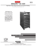
See Figures 3 and 4 for clarication.
Good
Bad
Ugly
Figure 3: Flat Component Mounting
Good
Bad
Ugly
Figure 4: Upright Component Mounting
B.2 Assembling the Board
Have all your tools ready|your soldering iron heated up, a sponge to clean
the iron, and a tool to clip component leads|before beginning.
The general strategy for assembling the board should be to mount small
at components (like DIP sockets, resistors, resistor packs, caps, and diodes)
rst, and thick, clunky components (like switches) last. It's up to you to
determine exactly what order you want to do things; most of the time, it
shouldn't matter.
The following list tells you some important special cases of component
mounting. Please read this list before you begin to assemble the board.
21
1{2 Minor Board Fixes
The solder mask|the green material on the board that keeps the solder from owing across connections where it shouldn't|needs to be
scraped away for the mounting pads for the bend sensors. Also, two
thin traces near each mounting pad need to be removed.
See Figure 5 for details. You will probably want to do these xes before
mounting any components.
1. cut away these two traces
2. scrape green solder mask
off of rectangular pad
3. scrape away green solder mask on component side of board
directly opposite pad diagrammed in #2;
4. repeat steps 1-3 for all four bend sensor mounting pads.
Figure 5: Bend Sensor Mounting Fixes
2{2 Determine the Component Side
All but two of the components mount on one side of the board. This
is the side with the printed component layout information. Mount
22
components so that their pins go down from this side (e.g., the parts
will obscure the printing when they are mounted properly).
Don't blow it and mount everything on the wrong side!! This would be
an drastic error.
3{2 Integrated Circuit U3 and DIP socket for U2
Mount U3 directly to the circuit board. Observe proper polarity|you
will have to desolder if you get it wrong! Be careful not to heat the pins
for too long. Note that you will have to cut away the center support
for the 28-pin DIP socket in order to t it over U3.
4{2 6811 Socket
When mounting the square black socket for the 6811, observe the following polarity: Pin one of the socket is labelled either a \1" or \2" on
the inside top of the socket. The pin indicated by this marking goes
into the square hole on the circuit board.
5{2 Capacitors C1, C2, and C17
These capacitors should be bend over to lie at on the board before
soldering.
6{2 MLED71 Infrared LEDs.
These LEDs are shaped in small rectangular packages. These are all
mounted such that the clear bubble (the LED's lens) faces outward
from the board, and the brown face with the two colored stripes faces
inward. See following comment about LED22 before installing.
7{2 LED22
This component gets a bit cramped because I underestimated the size
of the 4-pin DIP switch (SW6). Please mount LED22 after mounting
SW6 and the adjacent SW7 (the tilt sensor).
8{2 Resistors R3, R7, R12, and R28
These resistors have incorrect values printed on the circuit board. You
may want to install these resistors rst so you don't get confused. The
correct values are: R3=470
; R7=470
; R12=1k
; R28=30
, 2 watt.
23
9{2 Resistor R20 and Diode D8
Resistor R20 will not be used.
Mount diode D8 such that it spans over the holes for resistor R20.
The cathode of the diode mounts in the square hole as marked; the
anode mounts in the far hole alloted for R20.
10{2 R7 Fix
Firstly, note that R7 should be 470
, not 1k
as indicated on the
board.
To do this x, you will need to cut a trace and install a jumper wire.
You should use an X-acto knife or razor blade to cut the trace. You
should use thin wire-wrap wire as the jumper.
R7 mounts near the miniature speaker. After you have located the
resistor, nd its mounting hole nearest to the edge of the PC board.
Turn the board over: this hole should have a thin wire connecting at
right angles to a thicker wire that runs parallel to the edge of the board.
Cut the thin trace connecting R7 to this thicker trace. Do not sever
the thick trace itself.
For the jumper, cut a piece of wire-wrap wire about four inches long.
Locate R1 (near the reset switch). Flip the board over, and observe
that one terminal of R1 connects (via a thick, meandering trace) to
pin 5 of U15.
Solder one end of the jumper wire to this terminal of R1|it is the
terminal of R1 that is farther away from R7. Solder the other end of
the jumper to the terminal of R7 that you disconnected (the terminal
closer to the edge of the board).
11{2 R30
R30 (a 47k
resistor) was added to the circuitry after the board was
designed, so there are no mounting holes for it. Instead, it must be
mounted at against the back of the board. Mount R30 so that it
connects pins 3 and 4 of U16.
12{2 RP4 Fix
24
RP4 should be a 47k
4 resistor pack. If you have a resistor pack
that is 47k
5, you must clip o the last resistor. Cut o one resistor
from the unbanded end before mounting.
13{2 U8 Serial Line Fix
Using a short wire jumper, connect pins 1 and 3 of U8 (do this on the
underside of the board).
14{2 Resistor R22 and Diodes D3 and D9
These devices are not needed. Do not mount any components in the
holes alloted for them.
15{2 Photocells VR3 and VR4
These should be mounted so that they face over the front diagonal
corners of the board. Bend the leads at right angles as near to the
case as possible; after you solder them in, you can twist them slightly
toward their respective corner of the board. Be very careful to apply as
little heat as possible when soldering; photocells are extremely sensitive
to heat.
16{2 Missing Trace on RP2
The square terminal of RP2 needs to be connected to pin 20 of U7
(the IC pin to which the RP2 terminal is nearest). Use a discarded
piece of component lead to make this connection.
17{2 Sharp IR Sensors
Before mounting each Sharp IR sensor (IR-1 through IR-4), put small
pieces of electrical tape on the board to insulate the board from the
supporting metal sides of the Sharp sensors. Note that sensors IR-2
and IR-4 mount underneath the board.
18{2 D10, the TIL-99
This component must be bent over to point toward LED21 before
soldering. The lead near the metal tab of the transistor mounts in the
square hole.
25
19{2 Female Socket Header
Cut strips of socket header to mount in the Expansion Bus area (a 14long strip and a 9-long strip), the lower motor ports adjacent to U18
(a 6-long strip), and the Batt Out port (a 2-long strip).
20{2 RJ-11 Phone Jack
The phone jack mounts on the top of the board; unfortunately, the
pinout drilled into the board has a symettry problem. Do not mount
the jack from the underside of the board. Instead, bend the pins of
the jack before insertion such that they will t into the holes that are
drilled.
21{2 Preparing the LCD Display
Cut a 14-long strip of male socket header. Insert the short pins of the
header up from the underside of the LCD connector holes. Solder from
the top of the LCD display.
22{2 Mounting the Bend Sensors
Figure 6 shows how to mount the bend sensors. You may wish to see
this done in person before you go ahead and mount them.
23{2 Heatsink Mounting on U18
Slide one of the gold heatsinks onto U18 (L293D) before mounting it
into its socket. Be sure to keep track of the pin one orientation after
you've slid on the heatsink.
24{2 Piggy-backing the L293 Chips
Motor driver chips U17 (L293D) and U19 (L293B) will be piggy-
backed and soldered together before installing in their socket.
To perform this operation, begin by sliding the gold-colored heat sink
over U19. Then, press U19 over U17, as indicated in Figure 7. Make
sure to that you have the two chips in the same \pin one" orientation
with respect to each other! Then, solder them together. Try to have
them pressed together as closely as possible, rmly against the heat
sink.
26
Scrape off green solder
mask before soldering,
top and bottom of board
TOP OF BOARD
BOTTOM OF BOARD
Deform pins so that the end
of this sensor touches
the other sensor
Figure 6: Bend Sensor Mounting Technique
Slide-on Heatsink
Solder is applied to
each pin to piggy-back
the two chips.
U19 (L293B)
U17 (L293D)
Figure 7: Motor Chip Stacking Technique
27
B.3 Check-o Parts Listing
This parts listing may be used as a quick reference when assembling the
board. If you wish, use this list to check o each component after it is
mounted.
Instead of mounting components in order of their numbering, you may
be able to save time by selecting a component to be mounted on the board,
and then looking up its value here.
Note: if there is a discrepancy between the component value printed on
the board and the component value listed here, the value listed here are
correct. A complete list of the discrepancies was included earlier in the
assembly directions for the particular components that have new values.
B.3.1 Integrated Circuit Sockets
U1{52-pin PLCC U2{28-pin DIP
U4{16-pin DIP
U5{20-pin DIP
U7{20-pin DIP
U8{16-pin DIP
U10{14-pin DIP
U11{14-pin DIP
U13{16-pin DIP
U14{16-pin DIP
U16{8-pin DIP
U17{16-pin DIP
U19{none{special! U20{20-pin DIP
U3{none{special!
U6{20-pin DIP
U9{14-pin DIP
U12{16-pin DIP
U15{8-pin DIP
U18{16-pin DIP
U21{20-pin DIP
B.3.2 Resistors
All resistors are 18 watt, unless otherwise noted.
R1{5
, 1W
R4{1k
R7{470
R10{2.2k
R13{2.2k
R16{10k
R19{10k
R22{not used
R25{47k
R28{30
, 2W
R2{100
R5{1k
R8{1k
R11{2.2k
R14{2.2k
R17{10k
R20{not used
R23{47k
R26{100k
R29{3.3k
28
R3{470
R6{1k
R9{1k
R12{1k
R15{10k
R18{10k
R21{47k
R24{47k
R27{2.2M
R30{47k
B.3.3 Resistor Packs and Trimpots
All resistor packs are common ground, unless otherwise noted.
RP1{47k
9
RP4{47k
5
VR1{100k
RP2{47k
9
RP5{1k
5
VR2{100k
RP3{47k
7
RP6{22k
5 iso
B.3.4 Capacitors
C1{330 F
C4{0.1 F
C7{0.1 F
C10{0.1 F
C13{4.7 F
C16{10 F
C19{22 pF
C2{1 F
C5{0.1 F
C8{0.1 F
C11{0.1 F
C14{4.7 F
C17{47 F
C20{22 pF
C3{0.1 F
C6{0.1 F
C9{0.1 F
C12{2.2 F
C15{10 F
C18{4700 pF
B.3.5 Transistors
Q1{MPS2222A
Q2{MPS2222A
Q3{MPS2222A
B.3.6 Diodes
D1{1N4001
D4{1N4148
D7{1N4148
D2{1N4001
D5{1N4148
D8{1N4148
D3{not used
D6{1N4148
D9{not used
B.3.7 LEDs
LED1{red
LED4{red
LED2{red
LED5{red
LED3{red
LED6{red
29
LED7{red
LED10{green
LED13{green
LED16{MLED71
LED19{MLED71
LED22{MLED71
LED8{green
LED11{green
LED14{yellow
LED17{MLED71
LED20{MLED71
LED23{MLED71
LED9{green
LED12{green
LED15{yellow
LED18{MLED71
LED21{MLED71
B.3.8 Miscellaneous Components
XTAL{8 Mhz crystal
SPKR{miniature speaker element
L1{1H, 1A inductor
L2{1H, 1A inductor
B.3.9 Switches
SW1{toggle switch SW2{slide switch SW3{red button
SW4{micro button SW5{micro button SW6{4-pin DIP
SW7{large microswitch SW8{large microswitch SW9{large microswitch
SW10{large microswitch
B.3.10 Integrated Circuits
U1{68HC11A0
U2{60LP256
U4{74HC138
U5{74HC374
U7{74HC244
U8{74HC4053
U10{74HC132
U11{74HC04
U13{74HC4051
U14{74HC4051
U16{LM358
U17{L293D
U19{L293B
U20{74HC244
B.3.11 Sensors
IR-1{Sharp GP1U52Y
IR-3{Sharp GP1U52Y
IR-5{TRW OPB 5447-2
U3{74HC373
U6{74HC244
U9{74HC10
U12{74HC390
U15{LM386
U18{L293D
U21{74HC374
IR-2{Sharp GP1U52Y
IR-4{Sharp GP1U52Y
IR-6{TRW OPB 5447-2
30
IR-7{TRW OPB 5447-2
IR-8{TRW OPB 5447-2
VR3{CdS photocell
VR4{CdS photocell
VR5{CdS photocell
VR6{bend sensor
VR7{bend sensor
VR8{bend sensor
VR9{bend sensor
VR10{bend sensor
VR11{bend sensor
VR12{bend sensor
VR13{bend sensor
D10{TIL-99 phototransistor
PYRO{Eltec 447 pyroelectric sensor
MIC{electret condensor microphone
B.3.12 Connectors
J1{DC power jack, 2.1mm ID
J3{8-pin right angle Molex
J5{9 volt battery snap
J2{RJ11 right angle jack
J4{6-pin right angle Molex
31
B.4 Board Parts Layout
32
C Mechanical Assembly Guide
This guide will tell you how to assemble the Sensor Robot's chassis, wire the
touch sensors, and wire and install the motor/gearbox/wheel assembly.
Instructions
Please read through these instructions from start to nish before building anything!! If something is unclear, you may wish
to ask about it before doing it wrong.
1{2 Preparing the Gearbox.
Take apart the Red Fox car and remove the gearbox assembly.
There is a hidden screw that you must remove in order to take
the car apart without breaking it. The screw is located in the
\driver's cockpit" of the car, between the stickers labelled \Radio
Shack" and \23." After you remove the gearbox, clip the wires
short.
Desolder the wires connecting to the motors, and solder a new set
of four wires to the motors. Leave at least 12 inches in length to
these new leads.
2{2 Understanding the Chassis.
The chassis should be oriented so that the folded edges face down-
ward.
Any wires going from the PC board to the chassis (motor wires,
battery wires, sensor wires) are inserted into the underside of the
PC board.
Wires going underneath the chassis (e.g., the motor wires and
battery wires) enter through the oval hole on the chassis.
33
FRONT OF ROBOT
Touch
Sensor
Touch
Sensor
Caster Mounting Holes
Circuit Board
Mounting Hole
Circuit Board
Mounting Hole
Wiring Hole
Battery and Gearbox
Mounting Holes
‘‘B’’ holes
Circuit Board
Mounting Hole
Circuit Board
Mounting Hole
Touch
Sensor
‘‘A’’ holes
Touch
Sensor
Figure 8: Robot Chassis with Part Mounting Information, Top View
34
8-32 x 3/8" bolt
#8 lock washer
#8 nut
Figure 9: Caster Mounting Guidelines, Side View
4-40 x 1/2" bolt
4-40 x 3/4" bolt
#4 lock washer
#4 lock washer
Back of Robot
Robot Chassis
Motor/Battery Bracket
1/4" aluminum spacer
1" aluminum spacer
mounting tab
on gearbox
1-1/4" aluminum spacer
mounting tab
on gearbox
#4 lock washer
#4 lock washer
4-40 x 1/2" bolt
Radio Shack Red Fox
Motor/Wheel/Gear Assembly
4-40 x 3/4" bolt
Figure 10: Gearbox Mounting Guidelines, Side View
35
3{2 Mounting the Caster.
Begin your assembly by mounting the caster in the position indicated
by Figure 8. Use the 8-32 bolts, lock washers and nuts as indicated by
Figure 9.
4{2 Mounting the Gearbox Supports
Install the 1" aluminum spacers and 1 14 " + 41 " spacers that will support
the gearbox assembly. Do not install the gearbox at this time.
The two 1" spacers mount in the holes labelled \A" in Figure 8. The
two 1 41 " + 41 " spacer assemblies mount in the holes labelled \B."
Refer to Figure 10 for details about how to install the spacers.
4-40 x 5/8" screw
Touch Sensor
#4 simple washer
#4 lock washer
Chassis
#4 nut
Figure 11: Touch Sensor Mounting Guidelines, Side View
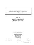
5{2 Mounting the Touch Sensors
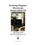
Mount the four touch sensors in the positions indicated in Figure 12.
Use the guidelines indicated in Figure 11 to select the combination of
bolts, nuts, and washers for proper mounting.
36
6{2 Wiring the Touch Sensors
Following the wiring diagram in Figure 12, wire the touch sensors to
the Sensor Robot board. Insert the wires from the back of the board,
and leave enough wire length so that the PC board can lie at next to
the chassis after you are done.
7{2 Installing the Gearbox
Referring again to Figure 10, bolt in the gearbox/motor/wheel assembly. Thread the 4-wire cable up through the oval mounting hole.
8{2 Soldering the Motor Wires to the PC Board
The goal here is to correctly wire the motors to the PC board. If you
get it wrong, when the software tells your robot to go forward, it will
end up turning right or going backward or something else.
You need your battery hooked up to do this. Go ahead and route your
battery cable through the oval hole and connect the battery.
Turn on your board and do not press reset. The motor outputs labelled
Left Motor should have a red LED lit, and the Right Motor
outputs should have a green LED lit. If this is not the case, turn your
board o, wait thirty seconds, and try again.
When you get the proper state, nd the wires that connect to the motor
driving the left wheel. Your goal is to wire these to the Left Motor
port so that when the red LED is lit, the left wheel is turning such that
the robot moves in a counterclockwise, backward pivot.
Insert the wires without soldering and see which way the wheel turns.
When you get the polarity right, solder the left motor wires in place.
Make sure that you insert the wires from underneath the board, and
that the wires are threaded through the oval hole.
Now, it's time for the right wheel motor. Your goal is to wire this
motor such that when the green LED is lit, the robot moves in a counterclockwise, forward pivot. Do it.
9{2 Mounting the PC Board to the Chassis
Follow the instructions given in Figure 13 to mount the circuit board
to the chassis. There are four mounting points as indicated in Figure 8.
37
FRONT OF ROBOT
SROSNES HCUOT
THGIR TFEL KCAB
Run wires from touch sensors
up into the bottom of the PC
board and solder from the top.
Make wires several inches
‘‘too long’’ so that PC board
can be easily flipped over
to lie next to chassis after
being wired.
Figure 12: Touch Sensor Wiring Guidelines, Top View
38
4-40 x 5/16" bolt
#4 nylon washer
PC Board
#4 nylon washer
3/4" aluminum spacer
Chassis
#4 lock washer
4-40 x 5/16" bolt
Figure 13: PC Board Mounting Guidelines, Side View
10{2 You Are Done
For now, at least. Parts that will be mounted later are: frame to support axles and hold battery, IR reectance sensors, IR shaft encoders,
and bend sensors.
(You can use a rubber band to hold your battery to the chassis of the
'bot until the support frame is ready.)
39