1
TRANSISTORIZED INVERTER
VFD SETUP SOFTWARE
FR-SW0-SETUP-WE
-Windows R (English) Version-
– INSTRUCTION MANUAL –
INTRODUCTION
Thank you for choosing the Mitsubishi Transistorized VFD Setup Software.
This instruction manual gives handling information and precautions for use of this software.
Incorrect handling might cause an unexpected fault. Before using this product, please read this manual
carefully to use it to the optimum.
Please forward this manual to the end user.
When reading this manual, note the following:
This manual is written on the basis that Windows 95 (English version) is the operating system. When using
Windows 98 with the software, refer to the corresponding Windows 98 instruction manual.
! The [return] and [enter] keys are represented by the
key.
! Drive D is described as the CD-ROM drive and Drive C as the hard disk drive.
! In keyboard operation, simultaneous pressing of keys is indicated by "+".
Example: Pressing the [Alt] and [G] keys simultaneously is indicated by (Alt+G).
Trademarks
! Windows is a registered trademark of Microsoft Corporation in the United States and/or other countries.
1) The formal name of Windows 3.1 is Microsoft Windows operating system Version 3.1.
2) The formal name of Windows 95 is Microsoft Windows 95 operating system.
3) The formal name of Windows 98 is Microsoft Windows 98 operating system.
! The DOS/V personal computer is a registered trademark of IBM Corporation.
! The "Mitsubishi Transistorized VFD Setup Software" is a registered trademark of Mitsubishi Electric Corporation.
The copyright and other rights of this software all belong to Mitsubishi Electric Corporation.
! No part of this manual may be copied or reproduced without the permission of Mitsubishi Electric Corporation.
! Other company and product names herein are the trademarks or registered trademarks of their respective
owners.
CONTENTS
1 OVERVIEW
1
1.1 Before Using This Software ....................................................................................................................................... 1
1.1.1 Packing list.......................................................................................................................................................... 1
1.2 Preparations for Startup ............................................................................................................................................ 2
1.2.1 System configuration .......................................................................................................................................... 2
1.2.2 Installing the Setup Software .............................................................................................................................. 3
2 FUNCTIONS
5
2.1 Starting the VFD Setup Software............................................................................................................................... 5
2.2 Settings...................................................................................................................................................................... 6
2.2.1 System Settings .................................................................................................................................................. 8
2.2.2 Communication Settings ..................................................................................................................................... 9
2.2.3 Environmental Setting ....................................................................................................................................... 11
2.3 Parameter................................................................................................................................................................ 12
2.3.1 All List Format ................................................................................................................................................... 12
2.3.2 Functional List Format ...................................................................................................................................... 16
2.3.3 Individual List Format........................................................................................................................................ 17
2.3.4 Basic Settings ................................................................................................................................................... 18
2.4 Monitoring ................................................................................................................................................................ 20
2.4.1 Data Display...................................................................................................................................................... 20
2.4.2 Meter Display .................................................................................................................................................... 21
2.4.3 Oscilloscopes.................................................................................................................................................... 22
2.4.4 Alarm History..................................................................................................................................................... 23
2.5 Diagnosis................................................................................................................................................................. 24
2.5.1 VFD Status........................................................................................................................................................ 24
2.5.2 Diagnosis .......................................................................................................................................................... 25
2.6 Test Running ........................................................................................................................................................... 27
2.6.1 Test Running..................................................................................................................................................... 27
2.6.2 Auto Tuning....................................................................................................................................................... 27
2.7 Saving, Reading and Printing the Files ................................................................................................................... 29
2.7.1 File types........................................................................................................................................................... 29
2.7.2 Saving method .................................................................................................................................................. 29
2.7.3 Reading the file ................................................................................................................................................. 30
2.7.4 Printing.............................................................................................................................................................. 30
2.8 Help ......................................................................................................................................................................... 31
2.8.1 Help contents .................................................................................................................................................... 31
2.8.2 Version information ........................................................................................................................................... 31
3 ERROR INDICATIONS
32
3.1 Error Codes ............................................................................................................................................................. 32
3.1.1 Error code lists .................................................................................................................................................. 32
3.1.2 Panel-displayed errors ...................................................................................................................................... 33
4 APPENDICES
34
4.1 Supplementary Software ......................................................................................................................................... 34
4.1.1 Introduction ....................................................................................................................................................... 34
4.1.2 Parameter files .................................................................................................................................................. 34
4.1.3 Parameter file edit software (PREDIT) .............................................................................................................. 35
CHAPTER 1
OVERVIEW
This chapter provides the fundamental "overview" for use of
this product.
Always read the instructions before using this software.
1.1 Before Using This Software .......................................1
1.2 Preparations for Startup.............................................2
When using this software to make communication with the inverters, set a
value other than 0 in Pr. 122 "communication check time interval" on the
inverter's operation panel. For the FR-S500 series, set a value other than 0
in the communication parameter n6 (336) "communication check time
interval".
(Refer to the inverter instruction manual for the setting method.)
CHAPTER 1
OVERVIEW
CHAPTER 2
FUNCTIONS
CHAPTER 3
ERROR INDICATIONS
CHAPTER 4
APPENDICES
1.1 Before Using This Software
OVERVIEW
1OVERVIEW
1.1Before Using This Software
! This software can be used effectively as a support tool for operations from startup to maintenance of the
Mitsubishi transistorized inverter. The following functions can be performed efficiently on the Windows
screen of a personal computer.
" System setting function
" Parameter editing function
" Monitoring function
" Diagnosis function
" Test running function
" File management function
" Help function
1.1.1 Packing list
After unpacking, check that the following items are contained in the package:
Item
Quantity
CD-ROM
1 disk
Instruction manual
1 book
1
1.2 Preparations for Startup
OVERVIEW
1.2Preparations for Startup
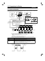
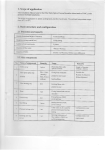
1.2.1 System configuration
The following devices are required to use the VFD Setup Software. Configure the system in accordance with
the instruction manuals of the corresponding devices.
2)
1)
3)
Mouse
VFD Setup Software
Converter *1
Communication option used
*2
PU connector used *2
Connection cable
RS-485/RS-422
Connection cable
Connector: RJ45 connector
Example: Tyco Electronics Corporation 5-554720-3
Cable: Cable in compliance with EIA568
(such as 10BASE-T cable)
Example: Mitsubishi Cable Industries, Ltd.,
SGLPEV 0.5mm×4P
(Twisted pair cable, 4 pairs)
Printer cable
Commercially available
printer
(ESC/P compatible)
Multidrop link system
Termination resistor
Distribution terminal
FR-A5NR
Power supply
NFB
Inverter
Inverter
Inverter
Inverter
Inverter
4) Inverters
Motors
*1: A converter commercially available is required when the personal computer uses the RS-232C port.
<Example of a commercially available product>
Model: FA-T-RS40 (Model with connectors and cable is also available)
Converter
Nagoya Sales Office, Mitsubishi Electric Engineering Co., Ltd.
*2: The PU connector or FR-A5NR (FR-A500 series, FR-F500 series) can be used to make communication.
(Refer to the corresponding instruction manual for details.)
1) Personal computer
2) Mouse
3) Setup software
4) Inverter
Model, Specifications, Etc.
One on which Windows 95 or Windows 98 (English version) operates
Mouse which can be connected to the personal computer
VFD Setup Software (FR-SW0-SETUP-WE)
FR-A520 (-NA), FR-A540 (-NA) (-EC) (-CH),
FR-A520L-75K, 90K, FR-A540L-75K to 280K (-NA) (-EC), FR-A560-NA,
FR-E520-0.1K to 7.5K (C) (-NA), FR-E540-0.4K to 7.5K (-NA) (-EC) (-CH),
FR-E520S-0.1K to 0.75K, FR-E520S-0.4K to 2.2K-EC (-CH), FR-E510W-0.1K to 0.75K (-NA),
FR-F520-0.75K to 55K, FR-F540-0.75K to 55K (-EC) (-CH),
FR-S520-0.1K to 3.7K-R, FR-S520S-0.1K to 1.5K-R, FR-S520S-0.2K to 1.5K-ECR (-CHR)
[Connection example between converter and inverter (PU connection port)]
Personal computer
(RS-232C)
FA-T-RS40
Connector
coupling
Inverter
(PU connection port)
Connector
coupling
2
OVERVIEW
1.2.2 Installing the Setup Software
To use the VFD Setup Software (FR-SW0-SETUP-WE), the files included in the setup disks must be installed
onto the personal computer.
If the former version of VFD setup software has been installed, delete it before starting the installation of the
latest one.
To install the VFD Setup Software, use the setup program (SETUP.EXE) on the Setup Disk (CD-ROM). The
setup program creates a directory on the specified hard disk and copies the required files.
Note: 1. Since the files in the Setup Disk are compressed, the VFD Setup Software will not operate by
merely copying the files. Always use the setup program to install the software.
2. Install the software in accordance with the Windows installation procedure.
! Installation procedure
Use the following procedure to register (install) the VFD Setup Software onto
the hard disk drive of the personal computer:
(1) Insert the CD-ROM into the CD-ROM drive.
(2) Press the [Start] button and choose the [Run] command.
Note: Shut down any other applications that are running.
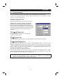
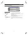
(3) Running the installation program
1) The [Run] dialog box appears.
2) Type "D:\SETUP" (use half-size letters) in [Open] and click the [OK] button or press the
the CD-ROM drive is drive D)
3) After that, perform operation in accordance with the setup guide (screen).
3
key. (When
OVERVIEW
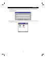
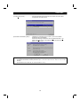
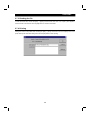
4) When file copying is over, the following screen appears. Always enter the user and company names
and click the [OK] button.
Installation is not completed unless the user and company names are entered.
5) When installation is over, the "VFD Setup S/W" and "VFD Setup S/W Help" icons are registered and
the following screen appears:
4
CHAPTER 2
FUNCTIONS
This chapter describes the "functions" for use of this
product.
Always read the instructions before using this software.
This chapter describes the "functions" for use of this product.
Always read the instructions before using this software.
2.1 Starting the VFD Setup Software ...............................5
2.2 Settings......................................................................6
2.3 Parameter ................................................................12
2.4 Monitoring ................................................................20
2.5 Diagnosis .................................................................24
2.6 Test Running ...........................................................27
2.7 Saving, Reading and Printing the Files ....................29
2.8 Help .........................................................................31
2
CHAPTER 1
OVERVIEW
CHAPTER 2
FUNCTIONS
CHAPTER 3
ERROR INDICATIONS
CHAPTER 4
APPENDICES
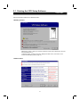
2.1 Starting the VFD Setup Software
FUNCTIONS
2FUNCTIONS
2.1Starting the VFD Setup Software
Start the VFD Setup Software with "INVSETUP.EXE".
<Primary screen>
*"#Next time no disp.": When you check #, the above screen will not appear from the next
time the software is run.
To display it again, check the check box "Display the initial screen", see section "2.2.3
Environmental Setting" (refer to page 11).
<Initial screen>
5
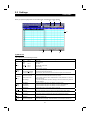
2.2 Settings
FUNCTIONS
2.2Settings
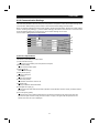
When you press the [OK] button on the initial screen, the following screen appears:
1)
2)
3)
4)
5)
6)
7)
8)
(1) Menu list
This software has the following functions:
Menu
Pull-Down Menu
Open
Ctrl+O
Close
File
(Alt+F)
Settings
(Alt+S)
Parameter
(Alt+P)
Monitor
(Alt+M)
Diagnosis
(Alt+N)
Function/Operation
Opens a file.
Closes the screen.
Save
Ctrl+S
Saves data.
Save As
Ctrl+A
Save data with a new name.
Print
Ctrl+P
Selects printing.
Exit
Performs exiting procedure.
System Settings
Sets the model, capacity (size) and option type. (Stations 00 to 31)
Communication Settings
Sets serial communication information.
Environmental Settings
Sets the directory where data will be stored and sets re-display of the initial screen.
All list Format
Shows and sets the parameter list.
Functional List Format
Shows and sets the related parameters function-by-function.
Individual list Format
You can register or delete a total of 32 parameters out of all parameters to or from two
different user groups.
Basic Settings
You can set the parameters required for starting up the inverter without being aware of
parameter numbers.
Data Display
Shows four pieces of data (up to four stations) in terms of values.
Meter Display
Shows four pieces of data (up to four stations) in terms of meter deflections.
Oscilloscopes
Shows four pieces of data (up to four stations) in terms of waveforms.
Alarm History
Shows the alarm history of all inverter stations connected.
VFD Status
Shows various data of all stations connected in real time in terms of values.
Diagnosis
Examine the estimated cause of the alarm in accordance with the alarm display.
Test Running Test Running
(Alt+T)
Auto Tuning
Gives the operation command from the personal computer to actually test run the inverter.
Performs auto tuning in accordance with the motor connected to the inverter.
Window
(Alt+W)
Cascade Display
Overlapping Windows.
Tile Display
Windows are side-by-side.
Help
(Alt+H)
Contents
About VFD Setup S/W
Various help functions (parameter explanations, function explanations, etc.)
Version information (copyright, version information, user and company names, etc.)
6
FUNCTIONS
(2) Description of various buttons and indications
1) Node
The station number selected is displayed.
2) [EXT] (Alt+X), [PU] (Alt+U) and [LNK] (Alt+L) buttons
You can choose the inverter operation mode for online operation.
" [EXT] button: External operation mode
" [PU] button: PU operation mode
" [LNK] button: Computer link operation mode
3) The operation mode and error codes appear. (Refer to page 32 for the error codes.)
Operation mode indications
" EXT. ..............................................External operation mode
" PU..................................................PU operation mode
" EXTJOG ........................................External jog mode
" PU JOG .........................................PU jog mode
" LNK................................................Computer link mode
" PU EXT .........................................PU-external combined mode
" TIME ..............................................Time scheduled operation
" SP..................................................Special mode
" No Node ........................................Time-out occurred in the online mode
In any other case, the error number at NAK error occurrence appears.
" When an alarm occurs, the operation mode and error codes are displayed in red.
" To display a warning, the operation mode and warning appear.
4) [ONLINE/OFFLINE] (Alt+O) button
" [ONLINE] (online) button: Online operation mode
" [OFFLINE] (offline) button: Offline operation mode
Click the corresponding button to select the online or offline mode.
5) System settings
You can set the environment of the inverters of stations 00 to 31.
Set the model, capacity and options for these inverters.
6) [New] button (Alt+E)
Used to make new system settings.
7) [System Read] button (Alt+Y)
Used to batch-read all inverters in the system with which the personal computer communicates.
8) [Confirmed] button (Alt+I)
You can register the data specified in the system settings.
7
FUNCTIONS
2.2.1 System Settings
This screen appears when you start this software and press the [OK] button on the initial screen.
On this screen, set the station numbers, models, capacities and plug-in options of the inverters connected.
Inverters can be set to stations 0 to 31.
(1) Station selection (Ctrl+N)
Click the required station number. That line is then chosen.
(2) Selection of model, capacity and options
When you double-click the selected line, the "VFD Structure"
panel (as shown on the right) appears. Set the model, capacity
and options and press the [OK] button to complete the settings.
Using the same procedure, set all inverter stations which
connected.
(3) [Confirmed] button (Alt+I)
After setting all stations, pressing the Confirmed button
completes the system settings.
(4) [New] button (Alt+E)
Press the New button to initialize (clear) the system settings/communication settings being edited.
(5) [System Read] button (Alt+Y)
Before pressing the [System Read] button, press the [ONLINE/OFFLINE] button to change the mode
indication to [ONLINE] and select the online operation mode. In the online operation mode, the personal
computer is switched to the inverter communication status and clicking the [System Read] button reads the
models, capacities and options of all stations (stations 0 to 31) and displays the stations connected (with
which the personal computer can communicate).
After reading, the settings are registered automatically.
When the system settings have not yet been made, the read stations are displayed. When the system
settings have already been registered, check is performed. If the check result is different from the read data,
select whether different points are displayed and changed or not.
Note: When the [System Read] button is pressed, the 100V or 200V class of the FR-E500 series is
displayed as the FR-E520-NA, and the 400V class is displayed as the FR-E540-NA.
When the model differs from that, change the model manually.
8
FUNCTIONS
2.2.2 Communication Settings
The VFD Setup Software uses the serial port of the personal computer to control the inverters through serial
communication. Before making communication, serial communication settings must be made.
When you start this software, the initial screen appears. Pressing the [OK] button displays the system setting
screen. Choosing the [Settings] → [Communication settings] command on the menu bar. The screen then
shows the following dialog box, where various communication settings can be made.
Communication settings will be described below:
5)
1)
2)
6)
3)
7)
4)
8)
9)
(1) Screen explanations
The values in parentheses are initial values.
1) Communication Port (1)
Choose the communication port of the personal computer.
2) Baud Rate (19200)
Set the communication speed.
3) Data Length (8)
Set the data bit length.
4) Parity Check (Even)
Specify the parity bit.
5) Stop Bit (2)
Set the stop bit length.
6) Check Sum (Check)
Set whether checksum is made or not.
7) Delimiter (CR)
Specify the delimiter at the data trailer.
8) Interrogate Time [sec] (1)
Set the interval at which data transmission (operation mode indication and error check) is always made to
the inverter.
9) Time Out [msec] (1000)
Set the time from when data is transferred from the personal computer to the inverter until when the
personal computer receives a reply from the inverter. If a reply is not given after the preset time has
passed, the "time-out" error is displayed.
9
FUNCTIONS
(2) Button settings
1) [OK] button
Recognizes the settings on the communication screen and returns to the system setting screen.
2) [Cancel] button
Cancels the communication settings and returns to the system setting screen.
3) [Reflect Default] button
Used to omit the setting of the values specified in communication settings from the next time onward.
4) [Default Read] button
Used to read the default values.
5) [Initial Value] button
Used to return to the initial values.
The above set values depend on the inverter connected. Set them after confirming the set values of the
communication function parameters of the inverter.
(3) Inverter communication settings
The values set for communication depend on the inverter and connection method.
Inverter
Connection Method
Operation mode
FR-A520(-NA)
FR-A520L
FR-A540(-NA) (-EC) (-CH)
FR-A540L (-NA) (-EC)
FR-F520
FR-F540 (-EC) (-CH)
PU connector
(RS-485 connector)
or
FR-A5NR
• When PU connector (RS-485
connector) is connected PU
mode
• When FR-A5NR is connected
LINK mode
FR-E520 (-NA)
FR-E520S (-EC) (-CH)
FR-E510W (-NA)
FR-E540 (-NA) (-EC) (-CH)
PU connector
(RS-485 connector)
PU mode
FR-S520-R
FR-S520S-R
FR-S520S-ECR (-CHR)
RS-485 connector
LINK mode
Setting Range
[Node]
[Baud rate]
[Stop bit]
[Data length]
[Parity bit]
[Delimiter]
Station 0 to 31
4800, 9600, 19200 bps
1 bit, 2 bits
7 bits, 8 bits
None, odd, even
None, CR, CR+LF
Note: When making communication with the inverters, set a value other than 0 in Pr. 122
"communication check time interval" on the inverter's operation panel. For the FRS500 series, set a value other than 0 in the communication parameter n6 (336)
"communication check time interval".
(Refer to the inverter instruction manual for the setting method.)
(4) Interrogate time
Set the interval at which data is always sent or received to or from the inverter.
It must be set to at least 2 seconds shorter than the communication check time interval setting of the inverter.
If its setting is longer than the communication check time interval setting, the inverter will come to an alarm
stop.
Note: The setting of short interrogate time may slow down the response of the menus and buttons on each
window depending on the operating model and communication speed.
10
FUNCTIONS
2.2.3 Environmental Setting
You can specify the data directory (place where data is saved) and default system file.
1)
2)
5)
3)
4)
(1) Screen explanations
1) Data Directory..................................You can change the directory where data will be saved.
2) Display the initial screen ..................Checking the check box displays the initial screen.
3) Default Sys File ...............................Shows the system file (*.MEL) which is automatically set when starting
of the software.
There is no default registered.
4) Browse.............................................Default system file browsing button.
Shows the file selection common dialog and displays the chosen file
name in the default system file text box.
5) When the parameter is read it is
distinguished automatically ..............Turn on the check box to hide the parameters read-disabled for
parameter batch-read or batch-verify from the error panel. (Refer to
page 15)
11
2.3 Parameter
FUNCTIONS
2.3Parameter
When system settings are complete, you can choose menu parameters.
Choose the [Parameter] → [All List Format], [Functional List Format], [Individual List Format] or [Basic
Settings] command in the menu to select the corresponding format, and set parameters. Any parameter
setting is changed by first entering new data in the Updated column and then pressing the [Write] or [Blk
Write] button. The new data is then displayed in the Current setting column, which shows the current settings
of the inverter.
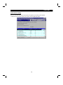
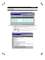
2.3.1 All List Format
By choosing the [Parameter] → [All List Format] command in the menu, all parameters of the inverter are
displayed as a list. When changing any parameter setting, enter a new value in the required parameter
key to register it.
column and press the
1)
2)
3)
4)
5)
6)
7)
8)
9)
10)
11)
12)
13)
14)
(1) Buttons and indications common to various parameter setting screens
1) Node (Ctrl+N) ..................................Indicates the inverter station number to be set (only the station
numbers registered in the system settings may be selected.)
2) Inverter operation mode ..................Used to choose/display the operation mode of the selected inverter
station number.
3) Online/offline (Alt+O) .......................To read/write the parameter values of the inverter, select the online
operation mode.
4) Setting Range..................................Indicates the setting range of the selected parameter.
5) Pr Jmp (Alt+J),
updated Val (Alt+V)..........................Shows the number and new value of the selected parameter. Values
may be entered directly into these columns.
6) Detail information (Alt+D,F1) ...........Shows the function explanation of the selected parameter.
12
FUNCTIONS
7) Change List (Alt+G) .........................Lists the parameters with the present set values which have been
changed from the initial values.
8) Parameter initialization (Alt+R) ........Initializes the parameters of the inverter. (The communication
parameters are not initialized.)
Choose the clearing method from among "Parameter Clear", "All
Clear" and "User Clear" on the following panel and click the [OK]
button to execute clear.
Note: Changing the Pr. 21 setting automatically switches the minimum setting increments of the
acceleration/deceleration-related parameters (Pr. 7, Pr. 8, Pr. 16, Pr. 45, Pr. 110, Pr. 111, Pr. 264,
Pr.265).
(Increments are 0.1s when Pr. 21=0, 0.01s when Pr. 21=1)
13
FUNCTIONS
9) Copy (Alt+Y) ................• System setting file (*.MEL)
Used to copy the parameter list as
a file to the inverter. Choose the
system setting file (*.MEL) and click
the [OK] button to display the panel
shown on the right. Making
selections at "Copy" and "Node"
and clicking the [OK] button reads
the parameter settings and sets
them to the Updated column.
Therefore, by performing block
write after that, they are copied to
the inverter. (Parameter copy
cannot be made between different
models.)
• Parameter setting file (*.PRM)
Choosing the parameter setting file
(*.PRM) displays the present
settings in the Updated value field
of the screen. (When only the
present settings are saved)
When there are both the present
settings and updated values,
display the parameter copy panel
(shown on the right) and select the
values to be copied.
10) Blk Read (Alt+B) .........Reads all parameters of the selected inverter station number.
11) Read (Alt+A) ...............Reads the data of the parameter numbers selected on the screen.
12) Blk Check (Alt+C) .......Batch-checks the parameters of the inverter against those of the personal
computer.
13) Blk write (Alt+K) ..........Writes new parameter values to the inverter.
(When there are no values in the Updated value field, the screen for selecting
whether the present settings will be written or not appears. Perform operation
following the screen prompts.)
14) Write (Alt+I) ................Writes the data of the parameter numbers selected on the screen.
14
FUNCTIONS
Note: If an error occurred during "block read", "block check" or "block write", the parameter list appears on
the panel. Double-clicking the error number in the displayed list shows the details of the error
definition on the panel.
[When the parameter is read it is distinguished automatically]
Turning on this check box automatically judges the read-disabled parameters and hide them from
the read error panel.
15
FUNCTIONS
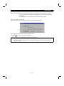
2.3.2 Functional List Format
By choosing the [Parameter] → [Functional List Format] command in the menu, the parameters are displayed
as a function list.
For parameter setting and changing, values may only be written in the online operation mode.
When changing any parameter setting, enter a new value in the required parameter column and press the
key to register it.
13)
1)
2)
3)
4)
6)
5)
7)
8)
9)
10)
11)
12)
(1) Various panel indications
1) Terminal allocation ..........................Lists the parameters concerned with the control circuit terminals.
2) Magnetic flux vector.........................Lists only the parameters for magnetic flux vector control.
3) Intelligent .........................................Shows the parameters related to the intelligent mode in which the
inverter performs operation after setting appropriate parameters
automatically.
4) Calibration .......................................Lists the parameters related to the calibration of the FM and AM
terminals and the bias/gain adjustments of the frequency setting
voltage (current).
5) Option ..............................................Lists the parameters of the values related to the options.
6) Special running................................Lists the parameters such as the functions used by making
pre-selection.
7) Motor torque ....................................Lists the parameters related to motor torque.
8) Frequency setting ............................Lists the parameters related to frequency.
9) Acceleration/deceleration ................Lists the parameters related to acceleration/deceleration.
10) Protection ......................................Lists the parameters related to the protective functions.
11) Monitor...........................................Lists the parameters related to the monitoring function.
12) Brake .............................................Lists the parameters related to braking.
13) Pr Jmp (Alt+J),
Updated Val (Alt+V).......................Show the selected parameter number and its new value. Values may
be entered directly into these columns.
16
FUNCTIONS
2.3.3 Individual List Format
By choosing the [Parameter] → [Individual List Format] command in the menu, you can select two different
user groups ("User Group 1", "User Group 2").
To these user groups, you can register a total of 32 parameters from among all parameters. Click the [Edit]
button (Alt+E). The following panel appears.
(1) Description of individual list editing operation
1) Registration........... Choose the items to be registered in the "Parameter List" and press the [Add>>>]
button to register them to the "Individual List".
2) Deletion................. Choose the items to be deleted in the "Individual List" and press the [<<<Delete]
button to delete them.
(2) After choosing the parameters, pressing the [OK] button completes the user setting and displays the
individually selected list in the following panel. To save the individual list, choose the [File] → [Save]
command from the menu to save it.
17
FUNCTIONS
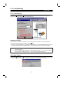
2.3.4 Basic Settings
Choosing the [Parameter] → [Basic Settings] command in the menu displays the following screen.
By entering data into the items shown on the screen, you can set the parameters without being aware of the
parameter numbers.
(1) Setting of each specification
Set the specification of each item in the Specification column. When the item has a [Click] button in the
Specification column, clicking that button shows choices. Make a choice and click the [OK] button.
60Hz is the maximum setting for operation speed.
(2) Registration of the specifications
After entering the specifications of all items, press the [Confirmed] button to register them. Pressing the
[Confirmed] button displays the following panel.
By pressing the [OK] button, the parameters are set automatically and the new values of the parameters that
may be set automatically are displayed.
18
FUNCTIONS
(3) Parameter setting
When the automatic settings of the parameters are registered, the following panel appears.
To write the new parameter values to the inverter, press the [Blk Write] button.
19
2.4 Monitoring
FUNCTIONS
2.4Monitoring
Choose the [Monitor] → [Data Display], [Meter Display], [Oscilloscopes] or [Alarm History] command from the
menu to select the corresponding monitor screen.
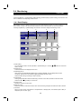
2.4.1 Data Display
Data Display shows four different signals such as the output frequency (those of up to four stations) in real
time in terms of values. The input and output statuses of the control terminals can also be monitored.
Choosing the [Monitor] → [Data Display] command from the menu displays the following screen:
1)
2)
5)
6)
7)
4)
3)
1) Node setting
You can enter the station number specified in "System Settings" or use the [ / ] button to choose the
station number.
2) Display items
Choose the items to be displayed in the menu.
3) Start/Stop (Alt+A)
After pressing the [ONLINE/OFFLINE] button to display [ONLINE], click the [Start] button to start
monitoring. (The function of this button toggles depending upon the mode.)
Click this button during monitoring to stop monitoring.
4) Hold (Alt+D)
Clicking the [Hold] button holds the data being monitored. In this state, the data can also be saved.
Click this button during holding to cancel hold.
5) Present value
Shows the real-time monitor value.
6) Maximum value
Shows the maximum value of the monitor value. Once monitoring is stopped, the maximum value is cleared.
7) I/O status
When you have chosen "Input Status" or "Output Status" in "Display Item", the I/O status (ON or OFF) is
displayed. (ON: red, OFF: gray)
20
FUNCTIONS
2.4.2 Meter Display
Meter Display shows four different signals such as the output frequency (those of up to four stations) in real
time in terms of meters. Meter Display handles show only data which can be indicated by meter deflections.
Choosing the [Monitor] → [Meter Display] command shows the following screen:
1)
Max Val.
2)
Present Val.
Perform operation as with Data Display.
The meter scales are automatically adjusted. After the parameters are batch-read, they are set to the
optimum values.
1) Meter display
Shows monitor values on the meters.
The present value is indicated by the black pointer and the maximum value by the red pointer.
2) Meter full-scale
Shows the full-scale value of the meter display. It can be changed by entering a new value.
21
FUNCTIONS
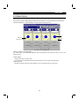
2.4.3 Oscilloscopes
Oscilloscopes pre-receives four different signals, such as the output frequency, from the inverters and shows
them on the personal computer screen as waveforms.
Choosing the [Monitor] → [Oscilloscopes] command from the menu displays the following screen:
1)
2)
3)
4)
[Operating procedure]
1) Setting (Alt+E)
Pressing the [Settings] button shows the "Measurement
Conditions" panel.
a. Choose the station number and measurement item.
b. Trigger signal setting
Choose the outside, inside or alarm trigger. For "Outside
Trigger", pressing the [Measurement Start] button starts
measurement. For "Inside Trigger", since the signal from the
inverter is used as a trigger signal, set the station number
measurement signal, timing, trigger terminal and conditions.
For "Alarm Trigger", the alarm occurrence signal of the inverter is used as a trigger signal. In this case,
the trigger settings valid are the station number and timing only.
Choose the displayed data from among "Before", "During" and "After" the trigger signal.
[Timing]
[Sampling Time] Set the interval of importing data. (50 to 60000msec)
[Conditions]
Choose the "Rise" or "Down" timing when the trigger is activated.
c. After setting the measurement conditions, press the [OK] button. The screen returns to Oscilloscopes
and the station numbers and measurement items set appear.
2) Measurement start (Alt+A)
Press the [ONLINE] button. For "Inside Trigger", press the [Measurement Start] button to start the
importing of data. On a trigger condition match, waveforms are displayed on the screen. For "Outside
Trigger", pressing the [Measurement Start] button starts the importing of data endlessly. After completion
or (suspension), press the [Play Back] button to display the data.
22
FUNCTIONS
3) Scale Change (Alt+C)
To change the vertical and horizontal axis scales of the
displayed waveforms, press the [Scale Change] button to
display the "Scale Change" panel, on which the scales are to
be changed.
The full-scale values on the vertical axes and time axes
(horizontal axes) of the displayed waveforms of the four
channels (four stations) can be changed.
Specify the sampling count as the unit for the time axis
(horizontal axis).
(Reference) Time converting method
: [sampling count] × [sampling interval]
4) PlayBack (Alt+B)
You can play back the measured oscilloscope data.
a. By pressing the [Play Back] button after the end of measurement, the oscilloscope data can be played
back. When the waveforms are being displayed, the screen is blanked once and the waveforms are then
played back.
b. You can play back saved oscilloscope data. By choosing [File] → [Open] to read the data, the
waveforms appear (are loaded).
2.4.4 Alarm History
Alarm History displays the history of eight past alarms of all inverter stations connected.
Choosing the [Monitor] → [Alarm History] command from the menu displays the following screen.
2)
3)
5)
4)
1)
1) Block Read (Alt+B)
Press the [ONLINE/OFFLINE] button to show [ONLINE] and then click the [Block Read] button to display
the alarm history of all stations specified in the system settings.
2) Alarm History
Lists the station numbers specified in the system settings and their history of eight past alarms.
3) Alarm Explanation
Clicking the alarm display column in the alarm history list shows the explanation of that alarm.
4) Alarm Clear (Alt+C)
Clicking the [Alarm Clear] button clears the alarm history of the chosen station inverter.
5) VFD Reset (Alt+R)
Clicking the [VFD Reset] button resets the chosen station inverter.
23
2.5 Diagnosis
FUNCTIONS
2.5Diagnosis
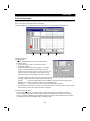
2.5.1 VFD Status
Choosing the [Diagnosis] → [VFD Status] command in the menu displays the following screen.
Note: This command can be chosen in the online mode only.
VFD Status: Displays the output current, output voltage, DC link V, Regenerative brake duty, THM factor,
Power on Time and Running Time data of all inverter stations specified in the system settings in
real time. The data can also be locked by pressing the [Hold] button (Alt+D). The values
displayed can be switched between absolute value indication and % indication (Alt+V).
24
FUNCTIONS
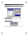
2.5.2 Diagnosis
Choosing the [Diagnosis] → [Diagnosis] command from the menu displays the following screen:
Alarm
Diagnosis (Alarm): Click the [Block Read] button (Alt+B) to batch-read the information of the inverters where
alarms have occurred. By clicking the corresponding item, its comment appears.
Note: This command can be chosen in the online mode only.
" Alarm Clear (Alt+C)
Clicking the [Alarm Clear] button clears the alarm history of the chosen station inverter.
" VFD Reset (Alt+R)
Clicking the [VFD Reset] button resets the chosen station inverter.
No Alarm
25
FUNCTIONS
Diagnosis (No Alarm): Shows the diagnosis items. When you choose the corresponding item, the panel
appears. Enter data in accordance with the display. As a result, the estimated cause,
etc. is shown.
For diagnosing the running status, the online mode must be selected.
[Alarm occurrence in online mode]
If an inverter alarm has occurred in the online mode, the following panel appears:
Clicking the [Yes] button shows the Diagnosis (Alarm) screen.
Clicking the [Help] button shows the alarm detail help.
Note: The above alarm panel appears only once in the online mode.
Once you have closed the alarm panel, it will not appear even during alarm occurrence. By changing
the online mode to the offline, then to the online again, however, the panel will appear again if an
alarm has occurred.
26
2.6 Test Running
FUNCTIONS
2.6Test Running
2.6.1 Test Running
Choosing the [Test Running] → [Test Running] command from the menu displays the following screen.
Note: This command can be chosen in the online mode only.
Operation procedure
1) Set the station number of the inverter to be run and the operation mode (PU or LNK (Link) operation).
2) Enter the running frequency and register it with the
key.
3) Click the [Jog FWD] (Shift+F5) or [Jog REV] (Shift+F6) button. The motor rotates while the button is being
pressed. The screen shows the output frequency, output voltage and output current being monitored.
Note: 1. If your inverter is the FR-E500 series, set any value other than "0" in Pr. 146 "frequency setting
command selection".
2. When selecting [Jog REV (Shift+F6)] for the FR-S500 series, set "---" in Pr. 63 "STR terminal
function selection". Setting other than "---" does not enable [Jog REV (Shift+F6)].
2.6.2 Auto Tuning
Choosing the [Test Running] → [Auto Tuning] command from the menu enables auto tuning. You have to set
the auto tuning parameters in advance. If they have not been set, the following screen appears:
27
FUNCTIONS
<Operation procedure>
1) Set the station number of the inverter to be run and the operation mode (PU or LNK (Link) operation).
2) Confirmation of the auto tuning parameters
Clicking the [Check] button (Alt+C) shows the parameters on the screen in a dialog box.
After entering the parameter set values, click the [Blk Write] button to write the new parameter values to
the inverter.
3) Click the [FWD] (Alt+D) or [REV] (Alt+R) button.
The LED block and monitor screen display the auto tuning status.
When Pr. 96 = "101", the motor is rotated. The motor stops on completion of auto tuning. If the auto tuning
has failed, follow the dialog box instructions.
Note: 1. In the offline mode, test running and auto tuning cannot be performed.
2. Before starting test running, check and if necessary adjust the parameters. Not doing so may
cause some machines to perform unexpected operation.
3. Provide safety backup devices such as emergency brakes to ensure that the machinery and
equipment are not put in hazardous conditions if the inverters become faulty.
4. Auto tuning is not available for the FR-F500 series and FR-S500 series. (Can be displayed on the
screen.)
28
2.7 Saving, Reading and Printing the Files
FUNCTIONS
2.7Saving, Reading and Printing the Files
2.7.1 File types
File Name
Description
*.MEL
Manages the system settings and parameter lists (all stations) as a single file.
*.ADT
Manages the alarm history data. (All stations)
*.MDT
Manages the data indication data in monitoring. (Data on one screen)
*.MMT
Manages the meter indication data in monitoring. (Data on one screen)
*.ODT
*.TXT, *.CSV
*.PRM
Manages the oscilloscope data in monitoring. (Data on one screen)
Manages the parameter list in a text file format.
Displays the parameter setting information.
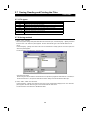
2.7.2 Saving method
1) *.MEL, *.TXT, *.CSV file
When the system settings and parameter lists to be saved are open, choose the [File] → [Save] command
from the menu. The "Save As" panel appears. Choose "Save file as type" to save the file with the "File
name".
Choose the [File] → [Save] command in the menu to overwrite the currently open file. If no file is open, the
"Save As" panel appears.
The file is saved in the "hard disk - invsupe" folder.
*Instructions for saving
When saving the file, the stations whose data are not opened are judged as "data absence". Therefore, if
the file is saved as it is, the previous data will be erased. Always save the file with the data open.
2) *.ADT, *.MDT, *.MMT and *.ODT files
Choose the [File] → [Save] command from the menu on the corresponding display screen. The "Save As"
panel appears. Choose "Save as type" to save the file with the "File name".
The file is saved in the "hard disk - INVSETUP" folder.
29
FUNCTIONS
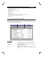
2.7.3 Reading the file
To read the saved file, choose the [File] → [Open] command from the menu. The "Open" panel appears.
Choose the file to be read and click the [OK] button to read the saved data.
2.7.4 Printing
Calling the screen to be printed and choosing the [File] → [Print] command in the menu displays the "Print"
panel. Make printer and other settings and click the [OK] button to start printing.
30
2.8 Help
FUNCTIONS
2.8Help
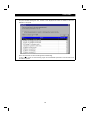
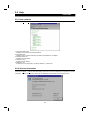
2.8.1 Help contents
Choosing the [Help] → [Contents] command from the menu displays the following screen:
1) About VFD Setup S/W
Explains how to use the VFD Setup Software.
2) Applicable VFD
Displays a list of inverters with which the VFD Setup Software is compatible.
3) VFD Parameter List
Explains each parameter.
4) VFD Alarm List
Explains inverter alarms.
5) NAK Error List
Explains the errors displayed in the setup software, e.g. NAK error.
2.8.2 Version information
Choosing the [Help] → [About VFD Setup S/W] command in the menu displays the copyright, the version
information, the user and company names set for installation and other data on the following screen:
31
CHAPTER 3
ERROR INDICATIONS
This chapter explains the "error indications" which may be
given during use of this product.
Always read the instructions before using this software.
3.1 Error Codes .............................................................32
3
CHAPTER 1
OVERVIEW
CHAPTER 2
FUNCTIONS
CHAPTER 3
ERROR INDICATIONS
CHAPTER 4
APPENDICES
3.1 Error Codes
ERROR INDICATIONS
3ERROR INDICATIONS
3.1Error Codes
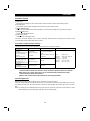
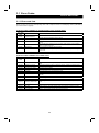
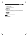
3.1.1 Error code lists
When any error occurs, the corresponding error code is output to the error code display column (indicated by
3) on the screen on page 6).
(1) Error codes related to a communication error (inverter side)
Error Code
(HEX)
Error Name
Definition
The number of errors consecutively detected in communication data from the computer
is greater than the permissible number of retries.
0(00H)
Computer NAK error
1(01H)
Parity error
The parity check result does not match the specified parity.
2(02H)
Sumcheck error
The sum check code in the computer does not match that of the data received by the
inverter.
3(03H)
Protocol error
Data received by the inverter is in wrong protocol or data receiving is not completed
within the predetermined time.
4(04H)
Framing error
The stop bit length is different from the setting.
5(05H)
Overrun error
New data has been sent by the computer before the inverter completes receiving the
present data.
6(06H)
Character error
The character received is invalid (other than 0 to 9, A to F, control code).
(2) Error codes related to an inverter error
Error Code
(HEX)
Error Name
Definition
17(11H)
Outside parameter range
The data specified for running frequency, parameter write, etc. is outside the setting
range.
18(12H)
Operation mode error
The present operation mode is not allowed to perform. Change the operation modes.
19(13H)
Running
The inverter is running.
20(14H)
Parameter write inhibit
Parameter write is inhibited.
22(16H)
No parameters
There are no parameters or related parameters have not been set.
23(17H)
No options
The preset option is not connected to the inverter.
24(18H)
Narrow error
There is no difference between analog value settings of Pr. 902 (Pr. 904) and Pr. 903
(Pr. 905).
25(19H)
Data range error
The data specified for set frequency write, etc. is outside the range.
26(1AH)
Instruction code error
A non-existing instruction code was sent to the inverter.
27(1BH)
Mode error
Mode error
33(21H)
Running in present mode
Mode change etc. cannot be made since the inverter is running in the present operation
mode.
34(22H)
With STF
Mode change etc. cannot be made since the forward rotation command is entered.
35(23H)
With STR
Mode change etc. cannot be made since the reverse rotation command is entered.
36(24H)
Operation mode specified
Cannot be executed in the present operation mode.
37(25H)
Pr. 75 specified
Since Pr. 75 is specified, inverter reset cannot be executed.
32
ERROR INDICATIONS
(3) Error codes related to a communication error (personal computer side)
Error Code
2000
Error Name
Definition
Normal termination
Communication terminated without fault.
2001
Time-out occurrence
Communication with the inverter cannot be made.
2002
Send data error occurrence Send data error
2003
Checksum error
The sum check code value of the data received by the computer is invalid.
2004
Send data error
Data from the inverter is invalid.
2005
NAK receive data error
Data from the inverter is invalid.
2006
Line offline
The present line is offline.
2007
Unconnected
This station number is not yet connected.
3.1.2 Panel-displayed errors
Display
Definition
There is no program file read from the EXE file. The program
directory is different.
Program setting environment is invalid. Redo setup again.
Data directory is invalid. After starting, make environmental setting.
Data directory setting is invalid.
The following file is not found. The program is terminated.
The user file is not in the specified directory.
Time-out occurred. Check the wiring and communication settings.
Communication stopped for some reason in the online mode.
REMARKS
When making communication with the inverters, set a value other than 0 in Pr. 122 "communication check
time interval" on the inverter's operation panel. For the FR-S500 series, set a value other than 0 in the
communication parameter n6 (336) "communication check time interval".
Refer to the inverter instruction manual for the setting method.
33
CHAPTER 4
APPENDICES
This chapter provides the "appendices" for use of this
product.
Always read the instructions before using this equipment.
4.1 Supplementary Software..........................................34
4
CHAPTER 1
OVERVIEW
CHAPTER 2
FUNCTIONS
CHAPTER 3
ERROR INDICATIONS
CHAPTER 4
APPENDICES
4.1 Supplementary Software
APPENDICES
4APPENDICES
4.1Supplementary Software
4.1.1 Introduction
The parameter file edit software (hereafter "PREDIT") is specifically designed to make changes/additions to the
models supported by the VFD setup software (hereafter "setup software") and additions/deletions/changes to the
display parameters. Please acknowledge that the PREDIT is not supported.
4.1.2 Parameter files
(1) What are parameter files?
Parameter files are text files which consist of information on the models compatible with the setup
software and the parameter information of those models. Installing the setup software into the personal
computer also installs the following files into the directory where the setup software is installed.
Applicable Model
FR-A500
FR-A560
FR-E500
FR-A500L
FR-F500
FR-S500
Parameter File Name
fra520. ine
fra540. ine
fra520na. ine
fra540na. ine
fra540ec. ine
fra540ch. ine
fra560na. ine
fre520. ine
fre520na. ine
fre520w. ine
fre52wna. ine
fre520s. ine
fre52sec. ine
fre52sch. ine
fre540. ine
fre540na. ine
fre540ec. ine
fre540ch. ine
fra52l. ine
fra54l. ine
fra54lna. ine
fra54lec. ine
frf520. ine
frf540. ine
frf540ec. ine
frf540ch. ine
frs520. ine
frs520s. ine
frs52sec. ine
frs52sch. ine
Description
FR-A520-0.4K to 55K
FR-A540-0.4K to 55K
FR-A520-0.4K to 55K-NA
FR-A540-0.4K to 55K-NA
FR-A540-0.4K to 55K-EC
FR-A540-0.4K to 55K-CH
FR-A560-0.75K to 55K-NA
FR-E520-0.1K to 7.5K
FR-E520-0.1K to 7.5K-NA
FR-E510W-0.1K to 0.75K
FR-E510W-0.1K to 0.75K-NA
FR-E520S-0.1K to 0.75K
FR-E520S-0.4K to 2.2K-EC
FR-E520S-0.4K to 2.2K-CH
FR-E540-0.4K to 7.5K
FR-E540-0.4K to 7.5K-NA
FR-E540-0.4K to 7.5K-EC
FR-E540-0.4K to 7.5K-CH
FR-A520L-75K, 90K
FR-A540L-75K to 280K
FR-A540L-75K to 280K-NA
FR-A540L-75K to 280K-EC
FR-F520-0.75K to 55K
FR-F540-0.75K to 55K
FR-F540-0.75K to 55K-EC
FR-F540-0.75K to 55K-CH
FR-S520-0.1K to 3.7K-R
FR-S520S-0.1K to 1.5K-R
FR-S520S-0.2K to 1.5K-ECR
FR-S520S-0.2K to 1.5K-CHR
(2) Parameter file structure
The parameter file consists of a machine information part and a parameter information part. The machine
information part is used to choose a model on the system setting screen and the parameter information
part is used to chiefly display the parameter screen.
[Machine information part]
" Model name (such as FR-A520)
" Model type code (NA, EC, CH...)
" Power supply capacity (100V class: 1, 200V class: 2, 400V class: 4)
" Model code
(FR-A500 series: &HA5, FR-E500 series: &HBF, FR-F500 series: &HF5, FR-S500 series: &H55)
" Allowable capacity (0.1K, 0.2K, 0.4K...)
" Rated current value (0.8A, 1.5A, 3A...)
" Connectable option (A5AX, A5AY...)
" Number of parameters
34
APPENDICES
[Parameter information part]
" Help context ID (number for help display)
" Parameter number
" Name
" Unit (Hz, V, A...)
" Step (1, 0.1, 0.01, 0.001)
" Factory setting
" Function-based list code (parameter displayed on the functional list screen)
" Setting range check flag (0: checked, 1: not checked)
" Setting range
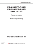
4.1.3 Parameter file edit software (PREDIT)
This software is specifically designed to edit the parameter file for the setup software, and cannot be used for
other applications. By editing and saving the file, it can be displayed on the parameter screen (all list,
functional list, etc.) as a setup software parameter file. You can make an updated inverter version or a special
or another inverter compatible with the setup software.
2)
3)
4)
1)
(1) Input items
1) Pr ....................................................Write the parameter number. Set the parameter numbers in the
ascending order and do not write the same parameter number.
2) Name ..............................................Write the parameter name.
3) Setting Range .................................Enter the parameter setting range and use "," and "-" for separation.
Example: 0 to 6, 9999 → 0-6, 9999
4) Range .............................................Choose whether the setup software range is checked or not. By
checking this column, a range check is not made in the setup
software.
35
APPENDICES
5)
6)
7)
8)
9)
10)
5) Minimum ..........................................Choose the minimum setting increment from among "1", "0.1", "0.01"
and "0.001" in the combo box.
6) Unit ..................................................Write the parameter unit. This column may be left blank for
parameters which do not have units.
7) Factory setting .................................Write the value set at the factory.
8) Help ID.............................................Write the help ID. Used to display help relating to the chosen
parameter. When adding a parameter, you cannot add its help and
therefore set "0".
9) Function list .....................................Enter the hexadecimal code as the function class for display on the
functional list format screen. Choosing "Edit" → "Functional List Code"
shows the functional list code edit panel.
10) Condition count..............................Shows the number of conditions set in parameter read condition
editing. (Refer to page 38)
Note: The number of parameters and the number of setting ranges need not be entered as they are set
automatically.
36
APPENDICES
(2) Functions
1) File
" Open
Opens the parameter file (Tool button available)
" Close
Closes the currently open file.
" Save
Overwrites the currently open file. (Tool button available)
" Save As
Shows the file saving combo box and saves the file with a new name.
" Print
Prints the open file. (Tool button available)
" Exit
Exits from the software.
2) Edit (may also be displayed with the right button of the mouse)
" Cut
Cuts the currently chosen range and pastes it to the clipboard. (Tool button available)
" Copy
Copies the currently chosen range and pastes it to the clipboard. (Tool button available)
" Paste
Pastes the data of the clipboard. (The clipboard data from another application may not be pasted
correctly.) (Tool button available)
" Insert & Paste
Inserts the data cut or copied on a line basis. (Tool button available)
Insert
Inserts a blank line to above the currently chosen line. (Tool button available)
" Delete
Deletes the currently chosen line. (Tool button available)
" Functional list code edit
Shows the functional code list of the currently chosen parameter.
Clicking the item to be displayed in the functional list and pressing the [OK] button automatically shows
the functional list code.
Functional List Code Edit Panel
37
APPENDICES
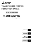
" Pr read condition edit
When performing Block Read or Block Check by the inverter setup software, no error indication will be
displayed by setting the parameter reading conditions, even if the parameters of inverter’s parameter
setting and setup software do not match. (Refer to page 14 for Block Read and Block Check of the
parameters.)
3)
4)
1)
2)
Note: Refer to the inverter instruction manual for the parameter reading conditions of the inverter.
1) Parameter condition
Pr: Parameter Number
=/<> : = (equal) or <> (not equal)
Cond1,Cond2 : Setting data
ex) When Pr. 19=9999, Pr. 60=1 to 6, Pr. 71<>2
38
APPENDICES
2) Operation mode condition
=/<> : = (equal) or <> (not equal)
Op mode: Select Operation mode
ex) In the external mode the reading is not correct
3) Inboard option condition
=/<> : = (equal) or <> (not equal)
As the inboard option name, input the option name which was set using the Machine information panel
(refer to page 8) of the setup software.
ex) The parameter can only be read with A5AX fitted
4) Number of Condition
Display setting condition. Automatic setting “OK” button.
Remarks
ADD/DEL button
ADD: Add disable read condition.
DEL: Delete select condition.
39
APPENDICES
" Machine information edit
Shows the machine information part edit panel of the parameter file. (Tool button available)
You can edit the inverter type, voltage code, model code, inverter rating, rated current and compatible
options.
Machine Information Edit Panel
3) Display
" Display column
Choose whether the display column (refer to the input items) is to be displayed or not.
" Toolbar
Choose whether the toolbar is to be displayed or not.
" Status bar
Choose whether the status bar is to be displayed or not.
" Font
Choose the font of the display list. The set font is also displayed after the next startup.
4) Window
" Cascade display
Shows the displayed windows side by side.
" Tile display
Shows the displayed windows one over another.
5) Help
" Contents
Shows the contents of help.
" Version information
Shows the version information panel.
6) Parameter count
Shows the number of parameters currently being displayed. Line insertion or deletion automatically
changes the number of parameters.
40
APPENDICES
7) Parameter No.
Shows the parameter number currently being chosen. After entering the parameter number, pressing the
return key displays the entered parameter number at the front of the list.
8) Automatic cell width adjustment
Double-click the item name (Pr., name, range check ...) in the list to adjust the cell width to the maximum
width of the column.
9) Mouse right-click
Press the right button of the mouse to show the edit menu.
10) Tool button function display
Placing the mouse on the tool button shows the button function details on the status bar.
11) By relating this software with the parameter file, you can open this software from the parameter file.
Note: Before editing the parameter file, always make a backup copy of the file.
41
REVISIONS
*The manual number is given on the bottom left of the back cover.
Print
*Manual Number
Apr., 1998
IB(NA)-66853-A
Nov., 1998
IB(NA)-66853-B
Revision
First edition
Additions
• Compatibility with the FR-E520-5.5K, 7.5K(-NA), FR-A520L-75K, 90K,
FR-A540L-75K to 280K(-NA)(-EC)
• APPENDICES
Partial additions
• Environmental Settings (default system file)
• Oscilloscope measurement conditions (Alarm Trigger, Sampling Time setting
range
• Alarm History (VFD Reset, Alarm Clear)
• File saving (Save, file format)
Jun., 1999
IB(NA)-66853-C
Additions
• Compatibility with the FR-E540-0.4K to 7.5K (-NA) (-EC) (-CH),
FR-E520S-0.4K to 2.2K-EC (-CH), FR-E510W-0.1K to 0.75 (-NA),
FR-F540-0.75K to 55K-EC (-CH)
• Compatibility with Windows 98
Aug., 2000
IB(NA)-66853-D
Additions
• Compatibility with the FR-A560-0.75K to 55K-NA, FR-F520-0.75K to 55K,
FR-S520-0.1K to 3.7K-R, FR-S520S-0.1K to 1.5K-R,
FR-S520S-0.2K to 1.5K-ECR (-CHR)
Partial additions
• Software installation disk
• System settings
Modifications
• Windows 3.1 delete
Dec., 2000
IB(NA)-66853-E
Partial addition
• Supplementary Software (Pr read condition edit function)
Modification
• Error code 18 (12H)