1
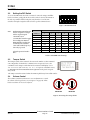
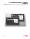
Command Center D1260
Installation Guide
D1260
D1260 Installation Guide
48101D
Page 2
© 2003 Bosch Security Systems
D1260
Contents
1.0
1.1
1.2
1.3
1.3.1
1.3.2
2.0
2.1
2.2
2.2.1
2.2.2
2.2.3
2.2.3.1
2.2.4
2.3
3.0
3.1
3.1.1
3.1.2
3.2
3.3
3.4
3.5
4.0
4.1
4.2
4.3
4.4
4.5
4.6
Introduction........................................................................................................................................................................................... 5
Manual Organization .......................................................................................................................................................... 5
Other Literature Referenced ............................................................................................................................................ 5
Documentation Conventions............................................................................................................................................ 5
Type Styles Used in this Manual ..................................................................................................................................... 5
Tips, Important Notes, Cautions and Warnings........................................................................................................... 6
D1260 Overview ................................................................................................................................................................................. 7
Specifications ...................................................................................................................................................................... 8
Front Panel Features .......................................................................................................................................................... 8
LCD Display ......................................................................................................................................................................... 8
Digital Keypad...................................................................................................................................................................... 8
Command Center Function Keys .................................................................................................................................... 9
Soft Keys............................................................................................................................................................................... 9
Audible Tones...................................................................................................................................................................... 9
Internal Features............................................................................................................................................................... 10
Installation ...........................................................................................................................................................................................11
Mounting ............................................................................................................................................................................ 11
Location Recommendations.......................................................................................................................................... 11
Mounting the Backplate ................................................................................................................................................. 11
Setting the DIP Switch ................................................................................................................................................... 12
Tamper Switch.................................................................................................................................................................. 12
Volume Control................................................................................................................................................................. 12
Wiring ................................................................................................................................................................................. 13
Programming the Panel ...............................................................................................................................................................15
Enabling the D1260 Command Center...................................................................................................................... 15
Programming Area Names............................................................................................................................................. 16
Programming Security Co. Info..................................................................................................................................... 16
99 + Enter “Setup?” Function ...................................................................................................................................... 16
Programming Custom Functions.................................................................................................................................. 17
Adding “Service Walk” to D7412G/D7412/D7212G/D7212 Service Menu .................................................. 17
Figures
Figure 1: D1260 Front Panel........................................................................................................................................................... 7
Figure 2: D1260 LCD Display......................................................................................................................................................... 8
Figure 3: D1260 Digital Keypad ..................................................................................................................................................... 8
Figure 4: D1260 Soft Keys .............................................................................................................................................................. 9
Figure 5: D1260 with cover removed......................................................................................................................................... 10
Figure 6: D1260 Backplate Mounting Options........................................................................................................................ 11
Figure 7: D1260 DIP Switch ........................................................................................................................................................ 12
Figure 8: Increasing/decreasing volume .................................................................................................................................... 12
Figure 9: 9000 Series panel to D1260 Flying Leads Wiring................................................................................................ 13
Figure 10: Wiring Connector........................................................................................................................................................ 13
Figure 11: Enhanced Command Center prompt in RAM IV.................................................................................................. 15
Figure 12: Enable Display Revision prompt in RAM IV........................................................................................................... 15
Figure 13: Incorrect Panel display............................................................................................................................................... 15
D1260 Installation Guide
© 2003 Bosch Security Systems
Page 3
48101D
D1260
Contents
Tables
Table 1: D1260 Installation Guide Manual Organization.......................................................................................................... 5
Table 2: Other Literature Referenced............................................................................................................................................ 5
Table 3: Upgrade Kits ....................................................................................................................................................................... 7
Table 4: D1260 Specifications ....................................................................................................................................................... 8
Table 5: D1260 Command Center Function Keys..................................................................................................................... 9
Table 6: Audible Tones ..................................................................................................................................................................... 9
Table 7: D1260 DIP Switch Settings..........................................................................................................................................12
Table 8: Area and Point Numbers and Area Name Text .........................................................................................................16
D1260 Installation Guide
48101D
Page 4
© 2003 Bosch Security Systems
D1260
Introduction
1.0
Introduction
1.1
Manual Organization
This manual is divided into 4 sections. A summary of each section is detailed in the table below.
Section
1
2
3
4
Description
Introduction
Overview
Installation
Programming the Panel
Table 1: D1260 Installation Guide Manual Organization
1.2
Other Literature Referenced
Throughout this manual, references will be made to other documentation. See the following table for the part numbers of
the literature that has other information about the D1260 Command Center.
Name of document
Part Number
D1260 User’s Guide
4998122475
D7212G Program Entry Guide
4998138538
D7212G Program Record Sheet
4998138542
D9412G/D7412G Program Entry Guide
47775
D9412G/D7412G Program Record Sheet
47488
Table 2: Other Literature Referenced
1.3
Documentation Conventions
These conventions are intended to call out important features, items, notes, cautions, and warnings that the reader
should be aware of in reading this document.
1.3.1
Type Styles Used in this Manual
To help identify important items in the text, the following type styles are used:
Bold text
Usually indicates selections that you may use while programming your panel. May
also indicate an important fact that you should note.
Bold Italicized
Denotes notes, cautions and/or warnings.
Italicized text
Refers you to a drawing, table, or other section of this document, or to another
document. Also used to symbolize names for records that you will create.
Courier New
Text
Indicates what may appear on the D1260 Command Center.
[CAPITALIZED
TEXT]
Indicates a specific key to be pressed.
Example: …press the [ENTER] key…
D1260 Installation Guide
© 2003 Bosch Security Systems
Page 5
48101D
D1260
Introduction
1.3.2
Tips, Important Notes, Cautions and Warnings
Throughout this document, helpful tips, important notes, cautions and warnings will be presented for the reader to keep
in mind. These appear different from the rest of the text as follows:
Important Notes - should be heeded for successful operation and programming. Also tips and shortcuts may
be included here.
Caution - These caution the operator that physical damage to the program and/or equipment may occur.
Warning - These warn of the possibility of physical damage to the operator, program and/or equipment.
D1260 Installation Guide
48101D
Page 6
© 2003 Bosch Security Systems
D1260
Overview
2.0
D1260 Overview
The D1260 Command Center is a SDI Bus compatible
device used with the D9412G, D7412G, D7212G, D9412,
D7412, D7212, and D9112 Control/Communicators with
versions 6.40 or higher. If you need to upgrade your
control panel, you may order the following upgrade kit at
no charge (see Table 3).
Control/Communicator
D9412G or D9412
D9112
D7412G or D7412
D7212
The D1260 features a keypad that illuminates when you
press the keys, a 4-line by 20-character display, and a builtin speaker that emits several distinct warning tones.
Upgrade Kit
D9499-0640 or higher
D9199-0640 or higher
D7499-0640 or higher
D7299-0640 or higher
Table 3: Upgrade Kits
The panel supplies all power and data requirements for the D1260 via a 4-wire connection. For specific panel
compatibility refer to the Panel Compatibility Chart in the Specifications Section of this document. See the Current
Rating Chart for Standby Battery Calculations provided in the Operation and Installation Manual for the specific panel
used with the D1260 to determine if you need an additional power supply.
You can program the panel to generate messages to a central station receiver identifying the supervised command center
that is in trouble. To supervise a command center, program CC# Number Supervised to Yes (see the Program Entry Guide
specific to your panel). If a command center loses communication with the panel for more than 10 to 15 seconds, the
command center buzzes and “Call for Service” and “Contact us at:” displays. Other command centers
connected to the system will display “Service Keypad”. The panel transmits a serial device trouble report (SDI
FAILURE in Modem, “TROUBLE ZN D” in BFSK) to the receiver.
The D1260 Command Center has the
following features on the front panel.
1. LCD Display (see Section 2.2.1
LCD Display on page 8)
2. Digital Keypad (see Section 2.2.2
LCD Display on page 8)
3. Soft Keys (see Section 2.2.3.1
Soft Keys on page 9)
4. Command Center Function
Keys (see Section 2.2.3
Command Center Function Keys
on page 9)
Figure 1: D1260 Front Panel
D1260 Installation Guide
© 2003 Bosch Security Systems
Page 7
48101D
D1260
Overview
2.1
Specifications
Power Requirements
Enclosure
Temperature
Display
Voltage
Nominal
Standby Current
Idle
95 mA
200 mA
Maximum (with speaker
volume and display backlight at
maximum)
4.6 in. x 8.2 in. 0.8 in.
(11.7 cm x 21 cm x 2 cm)
15.5 oz. (439 g)
Off White
GE Cycoloy CH10 UL94-HB Fire Rated
Intended for indoor use
+32°F to +120°F (0°C to +49°C)
+90°F +3°F (32°C +2°C)
Backlit LCD
3.4 in. x 1.4 in. (86.4 mm x 35.6 mm)
4 lines x 20 characters
Dimensions
(H x W x D)
Weight
Color
Material
Environmental
Operating
Humidity
Type
Size
12 VDC
Table 4: D1260 Specifications
2.2
Front Panel Features
2.2.1
LCD Display
The D1260 Command Center displays the latest status conditions of the security
system using words, numbers, and symbols in its display. When a series of
events occurs that affects the system, the D1260 displays each event in order of
its priority.
For a listing and description of the D1260 displays and command functions
available, consult the D1260 User’s Guide (P/N: 4998122475).
Figure 2: D1260 LCD Display
2.2.2
Digital Keypad
The D1260 Command Center features a digital keypad for entering user passcodes
and executing system commands in the panel.
Please refer to the D1260 User’s Guide (P/N: 4998122475) for instructions on how to
operate the system.
When a key is pressed, the D1260 emits a muted beep tone (see Section 2.2.4 Audible
Tones on page 9) to indicate that the entry has been accepted, and the keypad lights
and remains lit for 20 seconds.
Figure 3: D1260 Digital Keypad
D1260 Installation Guide
48101D
Page 8
© 2003 Bosch Security Systems
D1260
Overview
2.2.3
Command Center Function Keys
The D1260 has ten numeric
keys, two dedicated keys (see
Table 5) and 8 soft keys (see
Section 2.2.3.1 Soft Keys),
that are used to control your
system.
Key
Command
Picture
ENTER
Description
Use the [COMMAND] key in combination with one or
two numeric keys to perform a function.
Use the [ENTER] key to complete the entry of your
passcode at the command center.
Table 5: D1260 Command Center Function Keys
2.2.3.1 Soft Keys
There are eight “soft” keys (four on either side of the display) for
accessing menu functions, among other items.
When a selection is available, an arrow (< or >) is displayed next to
the key. To select the function, simply press the key next to it.
Figure 4: D1260 Soft Keys
2.2.4
Audible Tones
The D1260 Command Center has
a built-in speaker that produces
several distinct warning tones.
The speaker volume and display
brightness required can be
changed to meet the individual
needs of the user. You cannot
connect external annunciation
devices to the D1260. Anytime an
audible tone is emitted from the
D1260, the command center
backlight will illuminate.
Tone
Fire Signal
The signals in Table 6 are silenced
by entering a programmed
passcode with the appropriate
authority, or [COMMAND] + [4]
unless otherwise noted.
Invalid Key Buzz
Burglary Signal
Entrance Warning
Exit Warning
Keypad Encoding
Tone
Trouble Buzzer
Watch Tone
Description
When an area is in fire alarm, the D1260 emits a pulsed,
high-pitched “bell” tone.
When an area is in alarm, the D1260 emits a steady, highpitched “bell” tone.
The D1260 emits an intermittent beep tone during entry
delay periods to remind the user to disarm the area. This is
a programmable option.
The D1260 emits an intermittent beep tone during exit
delay and counts down the number of seconds left until
arming takes place. This is a programmable option.
When an invalid key, or sequence of keys, is pressed, the
D1260 emits a flat buzz tone.
The D1260 emits a muted beep tone as each key is pressed
to indicate that the entry has been accepted. To disable this
feature see Section 3.2 Setting the DIP Switch on page 12.
When a trouble event occurs, such as a service alert, the
D1260 emits a two-tone warble until you enter
[COMMAND] + [4].
When you activate the Watch feature ([Command] + [6]),
a single clean tweedle tone alerts the user anytime a watch
point is faulted. This option is programmable by point. To
disable the Watch Feature, press [Command] + [6] again.
Table 6: Audible Tones
D1260 Installation Guide
© 2003 Bosch Security Systems
Page 9
48101D
D1260
Overview
2.3
Internal Features
To access the inside of the D1260, the back cover must be removed. Using a small flat-blade screwdriver, gently push in
the two holes in the bottom of the D1260. As the tabs are pushed in, lift the back plate away from the rest of the unit.
The following internal features are
found:
1. DIP Switch
(6-position) - allows
you to select the
address of each
command center,
and enable/ disable
the keypad encoding
tone. (See Section 3.2
Setting the DIP
Switch on page 12)
2. EEPROM socket
(with example
EEPROM installed)
3. Wall Tamper Switch
(See Section 3.3
Figure 5: D1260 with cover removed
Tamper Switch on
page 12)
4. SDI Connector Jack
5. Volume Control Potentiometer (See Section 3.4 Volume Control on page 12)
D1260 Installation Guide
48101D
Page 10
© 2003 Bosch Security Systems
D1260
Installation
3.0
Installation
3.1
Mounting
The D1260 Command Center is a low profile, surface-mounted unit. It can also be mounted using the following optional
packages:
3.1.1
3.1.2
•
D56 Command Center Keypad Conduit Box - Protected surface mount or flush mount
•
D55 Command Center Desk Stand – Desktop
•
D54B-1260 Command Center Flush Mount Kit (Brass)
•
D54C-1260 Command Center Flush Mount Kit (Stainless)
Location Recommendations
•
Do not mount the command center in a location where it will be exposed to direct sunlight. Direct sunlight
can interfere with the D1260 display screen visibility and damage internal components.
•
Do not mount the D1260 in wet or moist locations.
Mounting the Backplate
The backplate for the D1260 keypad has a variety of
mounting holes to accommodate different mounting
standards.
1.
Standard 3-point mounting
2.
Single-gang electrical box
3.
Dual-gang electrical box
4.
Triple-gang electrical box
Figure 6: D1260 Backplate Mounting Options
To correctly mount the backplate, follow the steps below:
1.
Remove the backplate from the D1260 by using a flat-blade
screwdriver to press the two small tabs on the bottom of the D1260.
2.
Lift away the D1260 from the backplate.
3.
Ensure that the backplate is right-side up.
4.
Line up the mounting holes with the desired mounting method
(Standard 3-point, Single, Dual, or Triple-gang electrical boxes).
5.
Feed the 4-wire flying lead (from the panel) through one of the square holes at the bottom of the
mounting plate.
6.
Insert and tighten screws through the appropriate mounting holes to secure the mounting plate to the
wall.
D1260 Installation Guide
© 2003 Bosch Security Systems
Page 11
48101D
D1260
Installation
3.2
Setting the DIP Switch
To access the DIP switch, the back cover must be removed. Using a small flatblade screwdriver, gently push in the two holes in the bottom of the D1260. As
the tabs are pushed in, lift the back plate away from the rest of the unit.
ON
Switches 1 through 3 assign the address for the specific command center.
1
2
3
4
5
6
Figure 7: D1260 DIP Switch
Note:
Each D1260 Command Center
must be assigned to a unique
address. Supervising the
command center is
recommended. Switch 5 toggles
the encoding tone ON and
OFF. With the encoding tone
turned ON, the command
center will sound a beep every
time a key is pressed.
Always keep Switch 4 and 6
ON.
Switch
Address #
1
2
3
4¹
5*
1
ON
ON
ON
ON
ON
2
OFF
ON
ON
ON
ON
3
ON
OFF
ON
ON
ON
4
OFF
OFF
ON
ON
ON
5
ON
ON
OFF
ON
ON
6
OFF
ON
OFF
ON
ON
7
ON
OFF
OFF
ON
ON
8
OFF
OFF
OFF
ON
ON
¹ Always set this to the On position, * Encoding Tone On/Off
6¹
ON
ON
ON
ON
ON
ON
ON
ON
Table 7: D1260 DIP Switch Settings
3.3
Tamper Switch
The Tamper Switch, when activated, disconnects the SDI bus to that command
center. Regardless of whether the command center is supervised or not, the
command center’s tamper switch that had been activated will display “Call
for Service” and “Contact us at:”. To supervise command centers,
see CC# Supervised? in Command Center Assignments in the panel’s Program
Entry Guide.
The Tamper Switch is activated when the D1260 is pulled away from a flush surface.
3.4
Volume Control
The Volume Control Potentiometer is a screw adjustment to control
the volume of the keypad tones (See #5, Figure 5 on page 10). A flatblade screwdriver can be used to adjust it.
DECREASE
INCREASE
Figure 8: Increasing/decreasing volume
D1260 Installation Guide
48101D
Page 12
© 2003 Bosch Security Systems
D1260
Installation
3.5
Wiring
A 4-wire flying lead is required for the data and power connections between the D1260 and the panel. The D1260 comes
with a wiring assembly consisting of four color-coded flying leads and a female 4-pin connector plug at one end. Wire
resistance must not exceed 14 Ω.
It is recommended that 18 AWG wire be used when connecting a D1260 to a control panel.
To wire the D1260:
1.
Power down the panel.
2.
Using a small flat-blade screwdriver, gently push in the two
bottom tabs of the D1260 enclosure cover. As the tabs are pushed
back, lift the D1260 cover away from the backplate.
3.
Set the address switches as shown in Section 3.2 Setting the DIP
Switch on page 12.
4.
Connect the flying leads of
the wiring assembly
(provided) to the wires
from the panel, as shown
in Figure 9.
Represents the entire length
between panel and D1260
POWER + 32
DATA BUS A
31
DATA BUS B
30
COMMON
29
SDI Power
SDI Data Bus A
SDI Data Bus B
SDI Common
SDI Connector on
D1260 Keypad
Figure 9: 9000 Series panel to D1260 Flying Leads Wiring
5.
Turn the command center over and plug in the
wiring connector through the opening in the back
of the enclosure base (see Figure 10).
6.
Mount the command center base in the desired
location. (See Section 3.1.2 Mounting the Backplate
on page 11) Secure it in place using the mounting
holes inside the enclosure base.
7.
Replace the cover. Align and insert the top two
tabs of the enclosure cover into the top two tab
slots of the enclosure base. Hold the top edges of
the enclosure cover and base in position. Push the
tabs inward and press the enclosure and cover
together until the cover snaps into place.
Figure 10: Wiring Connector
D1260 Installation Guide
© 2003 Bosch Security Systems
Page 13
48101D
D1260
Installation
Notes:
D1260 Installation Guide
48101D
Page 14
© 2003 Bosch Security Systems
D1260
Programming the Panel
4.0
Programming the Panel
The D1260 Command Center is compatible with the D9412G, D7412G, D7212G, D9412, D7412, D7212, and D9112
Control/Communicators with versions 6.40 or higher. To program the D1260, version 1.15 or higher of the 9000MAIN
handler or version 3.60 or higher of RAM IV is required.
4.1
Enabling the D1260 Command Center
In RAM IV, it is located in the COMMAND CENTER (9000MAIN)
section and called Enhanced Command Center.
This prompt must be turned to YES for the command center addresses on
which D1260s will reside. Figure 11 assumes the D1260 is CC Address 1.
For more information, refer to the panel’s Program Entry Guide.
Figure 11: Enhanced Command Center
prompt in RAM IV
The Display Revision (Command 59) function (in RAM IV found under
USER INTERFACE (9000MAIN) Command Center Functions) must
be enabled (E) in the panel’s programming for the D1260 to work.
Figure 12: Enable Display Revision prompt
in RAM IV
After the first time a RAM programming session has been completed, but
before exiting RAM IV, the panel will have to be reset for use by using the
reset bye function (click the Reset panel checkbox before clicking OK).
In not, the display will show Incorrect Panel program settings…“Enhanced
CMD CTR” should be set to YES (see Figure 13).
Figure 13: Incorrect Panel display
D1260 Installation Guide
© 2003 Bosch Security Systems
Page 15
48101D
D1260
Programming the Panel
4.2
Programming Area Names
When the D1260 is installed with D9412G, D7412G, D9412, D7412, D7212, and D9112 Control/Communicators, Points
240 to 247 are used for the Area Text Name for the Area (1 to 8) that the D1260 is assigned to. When the D1260 is
installed with the D7212G Control/Communicator, Points 240 to 243 can be used for Area Text Name for the Area (1 to
4) that the D1260 is assigned to.
Note:
These points can still be used in D9412 and D9112 systems to detect alarms, although any custom point text that
is point specific will be displayed as the Area Name Text.
For example, if a D1260 is assigned to Area
1, and the name of Area 1 is
“WAREHOUSE,” then you would program
the word “WAREHOUSE” into Point 240.
See Table 8 for Area Name Text
assignments. This point text is used in the
D9412G/D9412/D9112 and
D7412G/D7412/D7212G/D7212 Control
Communicators to program the Area
Names.
4.3
Programming Security
Co. Info
Area #
1*
2*
3*
4*
5
6
7
8
Point #
240
241
242
243
244
245
246
247
Area Name Text – up to 16 characters
__ __ __ __ __ __ __ __ __ __ __ __ __ __ __ __
__ __ __ __ __ __ __ __ __ __ __ __ __ __ __ __
__ __ __ __ __ __ __ __ __ __ __ __ __ __ __ __
__ __ __ __ __ __ __ __ __ __ __ __ __ __ __ __
__ __ __ __ __ __ __ __ __ __ __ __ __ __ __ __
__ __ __ __ __ __ __ __ __ __ __ __ __ __ __ __
__ __ __ __ __ __ __ __ __ __ __ __ __ __ __ __
__ __ __ __ __ __ __ __ __ __ __ __ __ __ __ __
*D7212G uses Points 240 to 243 for Area Name Text.
Table 8: Area and Point Numbers and Area Name Text
When accessing the Help? function on the D1260, there is a menu item called Security Co. Info. Within this menu is the
ability to program your security company’s phone number in the event a subscriber needs to contact you. For the
D9412G, D9412, and D9112, the text programmed for User 249 Name (use RADXUSR2) is what will be displayed on this
screen. For the D7412G, D7412, D7212G, and D7212, the D1260 uses the text programmed in User 99’s Name (use
RADXUSR1 handler) text.
4.4
99 + Enter “Setup?” Function
The Setup function is accessed by pressing [9] [9] [Enter], Next>, then press the Setup?> soft key.
The adjustable functions that are available in this menu are
High Brightness,
Low Brightness,
and Contrast.
Each of these selections have <- Level +> soft keys on either side of the display that allows you to increase (+) or decrease
(-) the setting being displayed. The High and Low Brightness are associated to Command 49’s Bright Display and Dim
Display settings.
Also shown in this menu is the Command Center address,
whether the Encoding Tone is On or Off,
and the Command Center software revision.
D1260 Installation Guide
48101D
Page 16
© 2003 Bosch Security Systems
D1260
Programming the Panel
4.5
Programming Custom Functions
When programming Custom Functions for use on a D1260 Command Center, program the keystrokes as if you were
using a D1255 Command Center. Please refer to the panel’s Program Entry Guide and Program Record Sheet for full
details on how to program Custom Functions.
4.6
Adding “Service Walk” to D7412G/D7412/D7212G/D7212 Service Menu
The Service Walk function will not show up as a soft key in the Service Menu for D7412G, D7412, D7212G, and D7212
panels. For these panels this function must be enabled (set to E) or passcode enabled (set to P) within the panel’s
programming (9000MAIN Handler USER INTERFACE) for the Service Walk to be accessible from the D1260
command center. Then the Service Walk function should be programmed as Function 33 to the FUNCTION LIST and
enabled for the desired keypad.
D1260 Installation Guide
© 2003 Bosch Security Systems
Page 17
48101D
D1260
Programming the Panel
Notes:
D1260 Installation Guide
48101D
Page 18
© 2003 Bosch Security Systems
D1260
Programming the Panel
Notes:
D1260 Installation Guide
© 2003 Bosch Security Systems
Page 19
48101D
© 2003 Bosch Security Systems
130 Perinton Parkway, Fairport, NY 14450-9199 USA
Customer Service: (800) 538-5807; Technical Support: (888) 886-6189
48101D
Installation Guide
05/03
D1260
Page 20 of 20