1
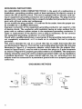
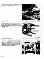
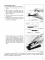
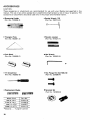
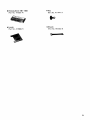
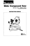
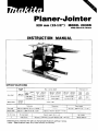
Planer-Jointer
320 mm (1242") MODEL 2030N
With Electric Brake
INSTRUCTION MANUAL
SPECIFICATIONS
I
Auto feed
Cutting
width
320 mm
112~1'2"'
I
I
Max. cutting depth
0 mm - 150 mm
I O ' - 5-7/87
150 mm - 240 mm
l5-7/8" - 9.1/2"1
High speed
2 mm 15/64")
1.5mm11/16"l
Low speed
3 mm I118")
2 mm 15/64")
Feed
.weed
Width
240 mm - 320 mm
(9-112" - 12.1/2"1
High
speed
1 mm15/128'1
1.5mm11/16,,)
Table SIZE
Fence size
Auto feed
320mmx 600mm 112.112" x 23-518")
Manual feed
155"
x 1,MOmm l 6 - 1 / 8 ' x 59")
8m
5m
126ft.l
(17ftI
Stock height
12.7 mm - 185 mm ( 1 12" - 7-114")
~
730mmx 105"
Low
speed
__
3 m m (1/8")
Manual feed
Feed rate /man
128-3/4" x 4-1/8"1
~
No. of knives
No load speed
Overall length IW x L x H I
Net weight
2
7,000 R/min.
780 mm x 1,500 mm x 775 mm 1 3 0 3 / 4 ' x 59" x 30-1 /2"l
150 kg 1330 Ibs)
BEFORE CONNECTING YOUR TOOL
TO A POWER SOURCE
Be sure you have read all
GENERAL POWER TOOL SAFETY RULES
GENERAL SAFETY PRECAUTIONS
(For All Tools)
1. KNOW YOUR POWER TOOL. Read the owner's manual carefully. Learn the
2.
3.
4.
5.
6.
7.
8.
9.
IO.
11.
12.
13.
14.
15.
2
tools applications and limitations, as well as the specific potential hazards
peculiar t o it.
KEEP GUARDS IN PLACE and in working order.
REMOVE ADJUSTING KEYS AND WRENCHES. Form habit of checking t o
see that keys and adjusting wrenches are removed from tool before turning it on.
KEEP WORK AREA CLEAN. Cluttered areas and benches invite accidents.
DON'T USE IN DANGEROUS ENVIRONMENT. Don't use power tools in
damp or wet locations, or expose them t o rain. Keep work area well lighted.
KEEP CHILDREN AWAY. All visitors should be kept safe distance from work
area.
MAKE WORKSHOP KID PROOF w i t h padlocks, master switches, or by
removing starter keys.
DON'T FORCE TOOL. It will do the job better and safer at the rate for which
it was designed.
USE RIGHT TOOL. Don't force tool or attachment t o do a job for which
it was not designed.
WEAR PROPER APPAREL. Wear no loose clothing, gloves, neckties, rings,
bracelets, or other jewelry which may get caught in moving parts. Nonslip
footwear is recommended. Wear protective hair covering t o contain long hair.
ALWAYS USE SAFETY GLASSES. Also use face or dust mask if cutting operation is dusty. Everyday eyeglasses only have impact resistant lenses, they
are NOT safety glasses.
SECURE WORK. Use clamps or a vise t o hold work when practical. It's safer
than using your hand and it frees both hands t o operate tool.
DON'T OVERREACH. Keep proper footing and balance at all times.
MAINTAIN TOOLS WITH CARE. Keep tools sharp and clean for best and
safest performance. Follow instructions for lubricating and changing accessories.
DISCONNECT TOOLS before servicing; when changing accessories such
as blades, bits, cutters, and the like.
16. REDUCE THE RISK OF UNINTENTIONAL STARTING. Make sure switch is
in off position before plugging in.
17. USE RECOMMENDED ACCESSORIES. Consult the owner's manual for
18.
19.
20.
21.
22.
23.
recommended accessories. The use of improper accessories may cause risk
of injury t o persons.
NEVER STAND ON TOOL. Serious injury could occur if the tool is tipped
or if the cutting tool is accidentally contacted.
CHECK DAMAGED PARTS. Before further use of the tool, a guard or other
part that is damaged should be carefully checked t o determine that it will
operate properly and perform its intended function - check for alignment
of moving parts, binding of moving parts, breakage of parts, mounting, and
any other conditions that may affect its operation. A guard or other part
that is damaged should be properly repaired or replaced.
DIRECTION OF FEED. Feed work into a blade or cutter against the direction
of rotation of the blade or cutter only.
NEVER LEAVE TOOL RUNNING UNATTENDED. TURN POWER OFF. Don't
leave tool until it comes t o a complete stop.
PROPER GROUNDING. This tool should be grounded while in use t o protect the operator from electric shock.
EXTENSION CORDS: Use only three-wire extension cords which have threeprong grounding-type plugs and three-pole receptacles which accept the
tool's plug. Replace or repair damaged or worn cord immediately.
VOLTAGE WARNING: Before connecting the tool t o a power source (receptacle,
outlet, etc.) be sure the voltage supplied is the same as that specified on the
nameplate of the tool. A power source with voltage greater than that specified
for the tool can result in SERIOUS INJURY t o the user - as well as damage t o
the tool. If in doubt, DO NOT PLUG IN THE TOOL. Using a power source with
voltage less than the nameplate rating is harmful t o the motor.
3
GROUNDING INSTRUCTIONS
ALL GROUNDED, CORD-CONNECTED TOOLS: In the event of a malfunction or
breakdown, grounding provides a path of least resistance for electric current t o
reduce the risk of electric shock. This tool is equipped with an electric cord having an equipment-grounding conductor and a grounding plug. The plug must be
plugged into a matching outlet that is properly installed and grounded in accordance with all local codes and ordinances.
Do not modify the plug provided -if it will not fit the outlet, have the proper outlet installed by a qualified electrician.
Improper connection of the equipment-grounding conductor can result in a risk
of electric shock. The conductor with insulation having an outer surface that is
green with or without yellow stripes is the equipment-grounding conductor. If
repair or replacement of the electric cord or plug is necessary, do not connect
the equipment-grounding conductor t o a live terminal.
Check with a qualified electrician or serviceman if the grounding instructions are
not completely understood, or if in doubt as t o whether the tool is properly
grounded.
This tool is intended for use on a circuit that has an outlet that looks like the
one illustrated in Figure A. The tool has a grounding plug that looks like the plug
illustrated in Figure A. A temporary adapter, which looks like the adapter illustrated in Figure B and C, may be used t o connect this plug t o a 2-pole receptacle
as shown in Figure B if a properly grounded outlet is not available. The temporary
adapter should be used only until a properly grounded outlet can be installed by
a qualified electrician. The green-colored rigid ear, lug, etc. extending from the
adapter must be connected t o a permanent ground such as a properly grounded
outlet box.
GROUNDING METHODS
FIG. A
t
Grounding Pin
4
FIG. B
-Cover
of Grounded
Outlet Box
FIG. C
Grounding
Means
ADDITIONAL SAFETY RULES
1. Don't use the tool in presence of flammable liquids or gases.
2. Handle the blades very carefully.
3. Check the blades carefully for cracks or damage before operation. Replace
cracked or damaged blades immediately.
4. Be sure the planer blade installation bolts are securely tightened before
operating.
5. Sharpen both blades evenly, or replace both blades or both cutterhead covers
at the same time.
6. Never make jointing or planing cut deeper than 3.2 m m (1/8inch).
7. Remove nails and clean the workpiece before cutting. Nail, sand or other
matter can cause blade damage.
8. Make sure the blade is not contacting workpiece before the switch is turned
on.
9. Wait until the blades attain full speed before cutting.
IO.
11.
12.
13.
14.
15.
16.
Keep hands away from rotating parts.
Stop operation immediately if you notice anything abnormal.
Always switch off and wait for blades t o come t o a complete stop before
adjusting any parts, cleaning out chips or approaching the blade.
Never stick your finger into the chip chute. Chute may jam when cutting
damp wood. Turn off the planer-jointer and then clean out chips with a stick.
Do not touch blades right after operation, they may be extremely hot and
could burn your skin.
Don't abuse cord. Never yank cord t o disconnect from receptacle. Keep cord
from heat, oil and sharp edges.
Do not use auto-planer and jointer at the same time. Overloading of the
motor can occur.
5
ADDITIONAL SAFETY RULES FOR JOINTER
1. Maintain the proper relationships of infeed and outfeed table surfaces and cutterhead blade path.
2. Do not perform jointing operations on material shorter than 140 m m (5-112
inches), narrower than 19 m m (3/4 inch), or less than 12.7 m m (112 inch) thick.
3.Do not perform planing operations on material shorter than 140 m m (5-1/2
inches), narrower than 19 m m (314 inch), wider than 155 m m (6-118 inches)
or thinner than 12.7 m m (1/2 inch).
4. Support the workpiece adequately at all times during operation.
5. Do not back the work toward the infeed table.
6. Always use hold-downlpush blocks for jointing material narrower than 76.2
m m (3inches), or planing material thinner than 76.2 m m (3inches).
SAVE THESE INSTRUCTIONS.
ADDITIONAL SAFETY RULES FOR AUTO-PLANER
1. Two or more pieces of narrow but similar thickness stock can be passed
through the auto-planer side by side.
However, allow some spacing between the stock t o permit the feed rollers
t o grip the thinnest piece.
Otherwise, a slightly thinner piece could be kicked back by the cutterhead.
WARNING
For Your O w n Safety, Read Instruction Manual Before Operating Jointer
1. Wear eye protection.
2. Never perform jointing or planing operation with cutter head or drive guard
removed.
3. Never make jointing or planing cut deeper than 3.2 mm (1/8 inch).
4. Always use hold-downlpush blocks for jointing material narrower than 76.2
m m (3inches), or planing material thinner than 76.2 m m (3inches).
5. Do not attempt t o perform an abnormal or little-used operation without study
and the use of adequate hold-down1push blocks, jigs, fixtures, stops, etc.
SAVE THESE INSTRUCTIONS.
6
HOW TO USE
AUTO-PLANER
1. Adjusting depth of cut
The maximum depth of cut changes in
terms of the cutting speed and the
width of the workpiece to be cut. See
Fig. 1.
Max. depth of cut
_1
low speed
1 I=-.
----
2 (5/64")
1 (5/128")
nrn
0
(6")
150
(8")
200
mm
(10")
250
(12")
300
Width
Fig. 1
Insert the workpiece flush with the infeed table top so that the front end of
the workpiece reaches a t least 20 to
30 mm (3/4 t o 1-1/8") beyond the
depth gauge. Turn the crank handle and
align the depth gauge with a graduation
on the scale plate. This graduation
indicates the depth of cut.
Fig. 2
2. Dimensional adjustment
The graduation on the scale bar aligning with the arrow i s the thickness of
the workpiece after the cut.
When cutting less than the maximum
depth of cut, first align the graduation
for the desired finished thickness with
the arrow and then cut the workpiece.
c
I
Fig. 3
7
3. Switchover of cutting speed
Turn the speed change lever to the right
for high speed, and to the left for low
speed.
CAUTION.
Change speeds while the tool is running,
but do not attempt to do so during an
actual planing operation.
Fig. 4
4. Chip deflector
The ejecting distance of chips can be
adjusted by means of the chip deflector.
To eject the chips in the near area, set
the chip deflector down.
Chip deflector
I
CAUTION :
When making heavy cuts, always set the
chip deflector a t the upper position to
prevent the chip chute from jamming.
Fig. 5
8
JOINTER
1. Cutting depth
Set the depth of cut with the depth
adjustment knob while watching the
graduation on the scale plate.
Fig. 6
2. Fence angle (0 - 45')
Set the depth of cut to "0" graduation.
Loosen the thumb screws holding the
fence in place. Pull out the fence by at
least 25 mm (1") and tighten the thumb
screws.
Loosen the hex bolts ( A ) and (B) and
tilt the fence.
Fig. 7
At the desired angle, tighten the hex bolts, making sure that the bolt (A) is tightened
first and the bolt (BI second. (Refer to Fig. 7). About 0.5 mm (1/64") clearance between, the lower edge of the fence and the table top is necessary for the correct setting.
3. Switch action
To start the tool, the key and the ONbutton must be pressed in.
Press the OFF-button to stop.
The tool is switched off automatically
when the electric current i s cut off.
CAUTION :
When not using the tool, remove the
key. (This prevents unauthorized operation.)
Fig. 8
9
OPERATION
1. Auto-Planer
Determine the depth of cut and the cutting speed in terms of the width of the workpiece you intend to cut. Insert the workpiece flush with the table top. When cutting
the long and heavy workpiece, lift up the end of the workpiece slightly a t the start and
the end of cutting to avoid gouging or sniping a t the extreme ends of the workpiece.
Two rollers are provided on top of the
chip cover to enable quick, efficient
return of the workpiece to the infeed
table side. This i s especially convenient
with two operators.
I
Return (for another pass)
CAUTION :
Stop the tool when the workpiece i s
stalled. Keeping the tool running with a
stalled workpiece causes the abnormal
wearing of the feed rollers.
Fig. 9
2. Jointer
Placement of hands during feeding
At the start of the cut, the left hand holds the workpiece firmly against the infeed
table and fence, while the right hand pushes the workpiece toward the blade. After the
cut is under way, the new surface rests firmly on the outfeed table. The left hand
should press down on this part, a t the same time maintaining flat contact with the
fence. The right hand presses the workpiece forward and before the right hand passes
over the cutterhead it should be moved to the workpiece on the outfeed table.
10
Jointing edge
Set the fence square with the table.
Hold the best face of the workpiece
firmly against the fence throughout the
feed. (Fig. 10)
CAUTION :
Cover the cutterhead with the safety
cover when the fence i s pulled out. (Fig.
1 1 ) . However, never touch the safety
cover when the jointer i s running.
Fig. 10
Jointing warped workpieces
If the workpiece is dished or warped,
press down when the workpiece moves
over the outfeed table to obtain a
smooth surface. (Fig. 10)
Using hold-downlpush blocks
For safety reasons, use hold-downlpush
Push blocks
Fig. 12
11
Direction of grain
Avoid feeding workpiece into the Jointer
against the grain as shown in Fig.13.
The result will be chipped and splintered
edges. Feed with the grain as shown in
Fig. 14, to obtain a smooth surface.
Wor kpiece
Outfeed table
lnfeed table
Cutterhead
Wrong feed -against the grain.
Fig. 1:
I-
VCorrect feed - with the grain
Fig. 1 4
12
CHANGING PLANER BLADES
1. Removing blades
a1 Remove
the screw on the outfeed side
of the chip cover. Then open the chip
cover.
Fig. 1
Loosen the hex bolt with the wrench and lift off the safety guard assembly.
Set the depth of cut for Jointer to maximum graduation.
*Push the lock plate in the direction of
the arrow and raise it slightly. Turn the
knob to lock the drum. (Fig. 16)
The drum can be locked a t the position
shown in Fig. 17 or Fig. 18.
Fig. 1(
Bolt
Drum cover
Fig. 17
Blade
Drum
cover
Fig. 1E
13
0
Lock the drum a t the position shown in Fig. 17 and loosen the hex bolts with the
socket wrench. Remove the hex bolts and the drum cover.
When removina the blade from the Auto-Planer, lock the drum a t the position shown
in Fig. 18 and push the blade out with
the screwdriver.
I
Fig. 19
.When removing the blade from the
Jointer, release the drum lock and turn
the knob to the position a t which the
blade can be pushed out with the screwdriver.
Fig. 20
2. Installing blades
0 Lock the drum a t the position shown in Fig. 18.
0
14
Insert the blade between the drum and
the blade holder. Set the blade so that
it will protrude by 2 mm (5/64") to
3 mm (1/8") from the drum. The holes
of the blade should be aligned with the
holes of the drum.
Blade
2 m m - 3mm
Blade holder
.On the Auto-Planer, press down on
both ends of the blades with wooden
levelers.
~
Fig. 22
*On the Jointer, set the leveler on the
outfeed table and slide it out over the
blade edge. The edge of blade should
just contact underside of leveler.
Fig. 23
Lock the drum a t the position shown in
Fig. 17.
Mount the drum cover and tighten the
hex bolts evenly and alternately.
*After unlocking the drum, press down
the wooden leveler on the blades slightly and turn the knob slowly in the direction of the arrow. (See Fig. 24).
The wooden leveler should slide about
3 mm (1/8") to 5 mm (3/16") when the
blade setting is perfect.
Fig. 24
15
VARIOUS ADJUSTMENTS
1. Adjusting infeed/outfeed rollers (Auto-planer)
NOTE :
The planer infeed and outfeed rollers are factory adjusted. If you notice the adjustment is off, kindly do as follows.
Use the wrench to loosen the installation nuts slightly. Turn the adjusting screw to
obtain a level of from 0.1 to 0.3mm above the table surface.
It i s relatively simple to make the setting so that a postcard can slip in and out between the roller and the leveler. After adjusting rollers, be sure to tighten installation
nuts securely.
A roller that protrudes too much will cause gouging or shiping in the workpiece and
rough surfaces.
Roller shaft
Roller
3 mm
Fig. 21
2. Extension roller adjustment
Gently loosen the hex bolts, set a rule
or yardstick on the table surface and adjust so that roller arm is slightly higher
than the table. Tighten the hex bolts
securely so that the roller arm surface is
a t 90" to the column.
16
MAINTENANCE
CAUTION :
Always be sure that the tool is switched off and unplugged before attempting to perform
inspection and maintenance.
Replacing carbon brushes
.Remove and check the carbon brushes
regularly. Replace when they wear down
to about 6 mm (1/4") or less. Keep the
brushes clean and free to slip in the
holders. Both brushes should be changed
a t the same time. Use only Makita carbon
brushes.
U
6 m m (1/4")
I
Fig. 2Z
Remove the screws that hold the chip
cover and the switch cover. Set the speed
change lever in the neutral position and
remove the switch cover. Open the chip
cover.
Fig. 29
.Use a screwdriver to remove the brush
holder cap as shown on the figure.
Fig. 30
17
.Take out the worn brush, insert the new
one and secure the brush holder cap.
Fig. 31
Cleaning
Always brush off dirt, chips and foreign
matter adhering to roller surfaces, motor
vents. Make sure that water or oil does not
enter the motor.
Fig. 3:
Lubrication (periodic)
Oil the chain (after removing the chain
cover), the column moving parts (contact
areas) and the crank handle. This periodic
lubrication should be performed with
machine oil. (Oiling should be done with
tool turned off and unplugged.)
I
Remove chain guard to
011
I
Fig. 33
18
Sharpening planer blades
(In case of blade width 155 mm (6-1/8”))
1. Remove the two wing nuts on the
holder.
2. Set the blade A and blade B on the
holder so that the heel of the blade will
be flush against C and D surface of the
holder respectively.
3. Tighten the wing nuts t o hold the blades
in the holder.
4. Sharpen with the dressing stone keeping
both blades contacting the dressing stone
surface a t the same time.
1
Fig. 31
Wing n u t
Blade B
\
Dsurface\
I
Fig.
3!
Immerse dressing stone in water for 2 or
3 minutes before sharpening. Hold the
holder so that blades both contact the
dressing stone for simultaneous sharpening a t the same angle. Stock removal i s
possible up to 7.5 mm (5/16”). Blades
may be used down to 24.5mm (1”)
width.
Fig. 36
To maintain product SAFETY and RELIABILITY, repairs, any other maintenance and
adjustment should be performed by Makita Authorized or Factory Service Centers,
always using Makita replacement parts.
19
ACCESSORIES
CAUTION :
These accessories or attachments are recommended for use with your Makita tool specified i n this
manual. The use o f any other accessories or attachments might present a risk of injury t o persons. The
accessories or attachments should be used only i n the proper and intended manner.
0
Sharpening Holder
(Part No. 123006-2)
0
Socket Wrench (13)
(Part No. 782213-2)
0
Triangular Rule
(Part No. 762001-3)
0
Wooden Levelers
(Part No. 441021 -7)
-
Hex Wrench
(Part No. 783202-0)
*Push Block
(Part No. 155508-0)
0
(+I
0
Replacement Blades
Screwdriver
(Part No. 783002-8)
Width (mm)
16-118")
.- . - .
155
-155
320
320
(6;1/8")
(12-1/2")
(12-1/2")
Material
20
1
I
[
I
I
0
Hex Flange Hd. Bolt M8x 30
(Part No. 251690-4)
Sprocket Set
(Part No. 191605-8)
Part No.
731021-8
731206-6
731035-7
731211-3
. . . Tungsten-carbide
Dressing Stone 180-1200
Key
(Part No. 741801-4)
(Part No. 411447-7)
Leveler
Wrench
(Part No. 41 1908-71
(Part No. 781202-4)
21
Seo -19-'84
320 mm (12-1/2")
PLANER-JOINTER
Model 2030N
22
US
23
Note: The switch and other part configurations
may differ from country to country.
24
MODEL 2030N
AiD
Sep
AtD
DESCRIPTION
19-84
US
DESCRIPTION
MACHINE
~
1
2
3
4
3
5
6
7
8
9
10
I1
16
2
2
3
17
2
1
1
1
1
IS
19
20
21
22
23
24
1
I
2
2
2
2
1
1
1
4
25
1
1
26
1
27
28
29
30
31
32
33
34
35
36
37
38
39
40
41
42
43
44
45
46
47
48
49
1
1
1
1
50
51
1
1
1
1
1
1
2
2
1
2
2
2
1
6
12
2
4
1
1
2
58
2
4
1
1
1
1
1
1
59
60
61
62
1
1
1
1
63
64
4
52
53
54
55
56
57
65
66
67
68
69
70
71
72
73
74
75
1
1
1
1
1
1
1
4
1
1
1
1
-
Pan Head S ~ r e wM5x12 !Wilh Washer]
Chip Cover
Chip Blast
Pan Head Screw M 5 x l 2 IWith Washer)
Plane Bearing 10
Rod 1 0 - 4 0 0
Pan Head Screw M5x12 IWith Washer]
Roller 2 6 - 3 7 5
Plane Bearing 10
Stop Ring E - 9
Switch Cover
Switch
Stop Ring E 9
Retaining Ring S 9
Spllny P,n 4 - 1 8
Rod
0 Ring 1
Lever 4 0
Countersunk Head Screw M4x10 !With Washeri
supportsr
Ball Bearing 609LLB
Flat Warher 10
Gear Complete 11 - 16 71
Flat Washer 10
Ball Bearing 620311B
Flat Washer 18
Compression Spring 21
Helical Gear 6 8
Gear Complete 13
Helical Gear 63
Compression Spring 21
Flat Washer 12
Brush Holder Cap
Carbon Brush
Motor Housing
Insulation Washer
Countersunk Head Screw M5x14 [With Washerl
Pan Head Screw M5x16 [With Washer)
Retainer L
Chip Breaker
Compresrlon Spring 4
Guide Bar
Rivet 2 5
Name Plate
Retainer R
Countersunk Head Screw M5x14 IWith Washerl
Pan Head Screw M5x16 [With Washer)
Pan Head Screw M 5 x 3 0 IWtth Washerl
v Pulley 9 - 3 M
Brackel
Ball Bearmg 6201110
Dust Seal 12
Fan 92
ARMATURE ASSEMBLY
[With Item 55 - 601
Dust Seal 1 0
Ball Bearing 6200LlB
FIELD ASSEMBLY
Gear Housing
Pan Head Screw M5xBO !With Washer)
Flat Washer 14
Helical Gear 7 9
Woodruff Key 4
Driving Shaft
Woodruff Key 4
Flat Washer 14
Gear Housing Cover
Pan Head Screw M5x45 1WiIh Washer]
Cham Cover
Chain 3 5 - 7 4
Reiain8ng Ring S - 12
Sorocket 15
76
77
78
2
79
80
81
82
83
84
85
86
1
1
1
1
1
1
1
1
87
2
88
1
1
1
1
1
1
1
1
1
89
90
91
92
93
94
95
96
97
98
1
1
6
1
99
I00
I01
102
I03
I04
105
I06
107
IO8
I09
110
I11
112
4
113
2
2
2
2
I14
115
116
117
118
119
I20
121
122
123
124
I25
I26
I27
I28
129
130
131
132
133
I34
135
I36
137
I38
I39
I40
141
142
I43
44
45
I46
847
1
4
1
1
1
1
1
1
1
1
4
2
2
2
4
8
2
1
1
1
1
1
1
1
1
1
4
12
2
1
1
1
1
2
1
1
1
1
2
2
1
1
2
1
- -
Pan Head Screw M5x12 IWilh Washerl
Rerasnmy Ring S - 1 2
Sprocket 1 0
Chain Cover Stay
Reraining Ring S - 1 2
Flat Washer 1 2
Needle Bearing 1212
Flat Washer 1 2
Bearing B O X
Pan Head Screw M 5 i l 2 !With Washerl
Strain Relief
Pan Head Screw M5x95 !With Washerl
Lock Plate
Spring Pin 4 18
Sleeve 5
Flat Washer 6
Pan Head Screw M5x25 [With Washer]
Spring Pin 4 - 2 4
Torsion Sprfng 12
Pan Head Screw M5x12 IWifh Warherl
Strain Relief
Countersunk Head Screw M6x20 lWnh Washerl
Main Frame
Spring Pin 8 - 7 0
Tension Core
Pan Head Screw M5x20 lWiIh Washer)
Tension Roller
Sleeve 5
Torsion Spring 13
Flat Washer 6
Pan Head Screw M 5 x 2 0 [With Washer]
Sprocket 15
Retaining Ring S - 12
Pan Head Screw M5x12 1WiIh Washer)
Pan Head Screw M5x16 IWith Washerl
Metal Cover B
Plane Bearing 14
Woodruff Key 4
Roller45 310
Plane Bearing 14
Compression Spring 13
Metal Cover A
Pan Head Screw M 5 x 1 6 lWith Washerl
Pan Head Screw M5x12 lWiIh Washer1
Blade Holder 3 0 0
Key 5
Urethane Sleeve I O
Poly V Bell 9 453
V Pulley 9 - 7 0
Hex Socket Head Bolt M5x16
Ball Bearing 6303LLB
Ball Bearing 6303LLB
Main Drum
Planer Blade 320
Drum Cover 300
Hex Flange Head Bolt MBx3O
Compression Spring 13
Retaining Ring S 12
Drum Cover
Ruler
Spring Pin 4 - 2 4
Pan Head Screw M5x16 !With Washerl
Torsion Spring 14
Hex Bolt M6x12
A d p s i Bed
Scale Plate
Pan Head Screw M 4 x 1 0 !With Washer)
Pan Head Screw M5x12 lWith Washerl
Ruler Holder L
Chip Guide
Her Bolt M6x12 [With Washer)
Safety cover
25
Sep.-19-84
MODEL 2030N
'itM
$tDDESCRIPTION
d;,'"
$ZD
DESCRIPTION
MACHINE
MACHINE
~
148
149
150
151
152
153
154
155
156
157
158
159
160
161
162
163
164
165
166
167
166
169
170
171
172
173
174
175
176
177
178
179
180
181
182
183
184
185
186
187
180
109
190
191
192
193
194
195
196
197
198
199
200
201
202
203
204
205
206
207
208
209
210
211
212
1
4
2
2
1
1
1
4
1
1
1
1
1
1
1
1
2
2
4
4
8
4
4
1
1
2
4
4
2
1
1
1
1
4
2
1
2
2
2
2
1
1
4
2
1
1
2
1
1
1
1
1
1
1
2
2
2
2
2
2
2
4
2
4
8
-
Ruler Holder R
Hex Flange Head Bolt M8xZO
Pan Head Screw M5x16 [With Washer)
Ruler Bar L
F i x Bed
Spring Pin 4 - 3 2
Knob 40
Hex Bolt Max25 lWith Washer)
Be"
cover
Ball Bearing 6203LL8
Sub Drum
Ball Bearing 6203LLB
Pan Head Screw M5x35 [With Washer1
Belt Cover
Key 5
Planer Blade 155
Blade Holder 155
Drum Cover 155
Hex Bolt M10x35
Lesi Spring
Hex Flange Head Bolt MBx30
Sleeve 10
Pan Head Screw M5x12 IWith Washer1
Hex Socket Head Bolt M5x18
Coupling
Spring Pin 10-60
Spring Washer 12
Hex Bolt M12x50
Pan Head Screw M5x14 lWith Washer)
Scale Plate
sprmg PI" 4 - 12
+ Binding Head Screw M8
Depth Gauge
Countersunk Head Screw M5x12 IWith Washer)
P0l"t Plate
Spring Pin 5-24
Indication Label
Hex Bolt Max38
Her Bolt MBx30
Tension Spring 6
pressure Plate
Ruler Supporter
Hex Bolt Max30 IWith Washer)
Wing Bolt M6x15
Flat Washer 14
Bar Holder
Hex Bolt Max30 lWith Warher)
Flat Washer 14
Spring Pin 6-24
Adjust Pole
Knob 70
Spring Pin 5-28
Indication Label
Rod 12-125
Stop Ring E - 9
Roller Arm
Plane Bearing 10
Roller 26-315
Rod 10-340
Plane Besrlng 10
Stop Ring E-9
Cap 6 0
Roller Arm
Felt Ring 60
Hex Bolt M8x20 lWnh Washer)
213
214
215
216
217
218
219
220
221
222
223
224
225
226
227
228
229
230
231
232
233
234
235
236
237
238
1
4
4
1
1
1
1
1
5
1
1
1
1
4
4
4
4
2
2
4
1
239
240
241
243
244
245
246
247
248
249
250
251
252
253
254
255
2 56
257
258
259
260
261
262
263
264
265
266
268
269
270
271
272
273
274
275
276
277
278
1
2
1
2
2
1
1
1
1
2
2
1
1
1
2
2
1
1
1
1
1
1
1
1
1
1
2
1
2
2
2
2
1
1
2
1
1
1
1
1
1
1
4
-
Note' The switch and other part SpeCifiCatiOnsmay differ from country to country.
Table
~ B XNu1 M6
"an Head Screw M6x50
l e x NulM12
Spring Washer 12
:la1 Washer 12
3D"g 53
Handle Supporter
Hex Bolt M6x35 IWith Washer)
Thrust Needle Bearing 1520
Straight Bevel Gear 28
Screw TM25
Stable Bare
3olumn
Snap Ring 55
3ellows
Snap Ring 55
Hex Nut M10
'la1 Washer 10
Spring Pin 8 - 7 0
Stable Bars
U t Washer 11
Hex Bolt M10x140
Pan Head Screw M5x12 [With Weshe0
Strain Relief
CORD ASSEMBLY
U s e m b l e d Cord Plug & Item 2391
Cord Guard
Pan Head Screw M5x12
Strain Relief
Hex BDII ~ 1 0 x 1 0 0
Flat Washer 11
- Bolt M10
Base
Grip 30
Flat Washer 10
Flat Washer 10
Hex Nut M10
Handle 175
Woodruff Key 4
Split Pin 3 0-25
Hex Bolt MBx20
Compression Spring 16
Flat Washer 16
Handle Shaft
Straight Bevel Gear 14
Retaining Ring S - 12
Woodruff Key 4
Pen Head Screw M5x14 lWith Washer)
Scale Bar
Plane Bearing 10
Roller 26-265
Plane BBarlng 10
Rod 10-315
Pan Head Screw M5x12 IWith Washer)
Key
Pan Head Screw M4x10
Hex Nut M10-17
Pan Head Screw M5x12
set Plate
Pan Head Screw M5x10
Knob 20
Pan Head Screw M5x12
Spring Pin 4-18
Flat Washer 8
IWith Washer)
lWith Washerl
lWith Washer)
lWith Washer)
US
...
..... ..... .. .. ... . .
.
..
.
. . . .. .... .. ..... .. .. ..-.
.-.
. .. .. ..
MAKITA LIMITED ONE YEAR WARRANTY
Warranty Policy
Every Makita tool is thoroughly inspected and tested before leaving the factory. It is warranted to
be free of defects from workmanship and materials for the period of ONE YEAR from the date of
original purchase. Should any trouble develop during this one-year period, return the COMPLETE
tool, freight prepaid, to one of Makita’s Factory or Authorized Service Centers. If inspection shows
the trouble is caused by defective workmanship or material, Makita will repair (or at our option,
replace) without charge.
This Warranty does not apply where:
repairs have been made or attempted by others:
repairs are required because of normal wear and tear:
The tool has been abused, misused or improperly maintained;
alterations have been made to the tool.
IN NO EVENT SHALL MAKITA BE LIABLE FOR ANY INDIRECT, INCIDENTAL OR CONSEQUENTIAL DAMAGES FROM THE SALE OR USE OF THE PRODUCT. THIS DISCLAIMER
APPLIES BOTH DURING AND AFTER THE TERM OF THIS WARRANTY.
MAKITA DISCLAIMS LIABILITY FOR ANY IMPLIED WARRANTIES, INCLUDING IMPLIED
WARRANTIES OF “MERCHANTABILITY” AND “FITNESS FOR A SPECIFIC PURPOSE,”
AFTER THE ONE-YEAR TERM OF THIS WARRANTY.
This Warranty gives you specific legal rights, and you may also have other rights which vary from
state to state. Some states do not allow the exclusion or Limitation of incidental or consequential
damages, so the above limitation or exclusion may not apply to you. Some states do not allow
limitation on how long an implied warranty lasts, so the above limitation may not apply to you.
Makita Corporation
3-11-8, Sumiyoshi-cho,
Anjo, Aichi 446 Japan
883441 - 065
PRINTED IN JAPAN
1991 - 8 - N