1
ARC-101
ATM Rate and Media Converter
Installation and Operation Manual
Notice
This manual contains information that is proprietary to RAD Data Communications. No part of this
publication may be reproduced in any form whatsoever without prior written approval by RAD Data
Communications.
No representation or warranties for fitness for any purpose other than what is specifically mentioned in
this manual is made either by RAD Data Communications or its agents.
For further information contact RAD Data Communications at the address below or contact your local
distributor.
RAD data communications
Headquarters
12 Hanechoshet Street
Tel Aviv 69710 Israel
Tel: 972-3-6458181
Fax: 972-3-6498250
E-mail: rad@ rad.co.il
RAD data communications
US East
900 Corporate Drive
Mahwah, NJ 07430 USA
Tel: (201) 529-1100
Fax: (201) 529-5777
E-mail: market@radusa.com
© 1999 RAD Data Communications
RAD data communications
US West
3631 South Harbor Boulevard
Suite 250
Santa Ana, CA 92704
Tel: (714) 850-0555
Fax: (714) 850-1555
Publication No. 334-200-03/99
Warranty
This RAD product is warranted against defects in material and workmanship for a period of one year
from date of shipment. During the warranty period, RAD will, at its option, either repair or replace
products which prove to be defective. For warranty service or repair, this product must be returned to
a service facility designated by RAD. Buyer shall prepay shipping charges to RAD and RAD shall pay
shipping charges to return the product to Buyer. However, Buyer shall pay all shipping charges, duties
and taxes for products returned to RAD from another country.
Limitation of Warranty
The foregoing warranty shall not apply to defects resulting from improper or inadequate maintenance
by Buyer, Buyer-supplied firmware or interfacing, unauthorized modification or misuse, operation
outside of the environmental specifications for the product, or improper site preparation or
maintenance.
Exclusive Remedies
The remedies provided herein are the Buyer’s sole and exclusive remedies. RAD shall not be liable for
any direct, indirect special, incidental, or consequential damages, whether based on contract, tort, or
any legal theory.
Safety Warnings
The exclamation point within a triangle is intended to warn the operator or
service personnel of operation and maintenance factors relating to the
product and its operating environment which could pose a safety hazard.
Always observe standard safety precautions during installation, operation and maintenance of this
product. Only a qualified and authorized service personnel should carry out adjustment, maintenance
or repairs to this instrument. No adjustment, maintenance or repairs should be performed by either the
operator or the user.
Telecommunication Safety
The safety status of each of the ports on the ARC-101 is declared according to EN 41003 and is
detailed in the table below:
Safety Status
Ports
SELV*
ATM, VTP/155, CX/BBC/155, T3, E3
TNV**
operating within limits of SELV
* SELV = Safety Extra-Low Voltage
** TNV = Telecommunications Network Voltage
E1
Regulatory Information
FCC-15 User Information
This equipment has been tested and found to comply with the limits of the Class A digital device,
pursuant to Part 15 of the FCC rules. These limits are designed to provide reasonable protection
against harmful interference when the equipment is operated in a commercial environment. This
equipment generates, uses and can radiate radio frequency energy and, if not installed and used in
accordance with the instruction manual, may cause harmful interference to the radio communications.
Operation of this equipment in a residential area is likely to cause harmful interference in which case
the user will be required to correct the interference at his own expense.
Warning per EN 55022
This is Class A product. In a domestic environment, this product may cause radio interference, in
which case the user may be required to take adequate measures.
Declaration of Conformity
Manufacturer’s Name:
RAD Data Communications Ltd.
Manufacturer’s Address:
12 Hanechoshet St.
Tel Aviv 69710
Israel
declares that the product:
Product Name:
ARC-101
Conforms to the following standard(s) or other normative document(s):
EMC:
Safety:
EN 55022 (1994)
Limits and methods of measurement of radio disturbance
characteristics of information technology equipment.
EN 50082-1 (1992)
Electromagnetic compatibility - Generic immunity standards
for residential, commercial and light industry.
EN 60950 (1992/93)
Safety of information technology equipment, including
electrical business equipment.
Supplementary Information:
The product herewith complies with the requirements of the EMC Directive 89/336/EEC and the Low
Voltage Directive 73/23/EEC. The product was tested in a typical configuration.
Tel Aviv, January 23rd, 1997
Haim Karshen
VP Quality
European Contact: RAD Data Communications GmbH, Lyoner Strasse 14, 60528 Frankfurt am Main, Germany
Contents
CHAPTER 1 – INTRODUCTION
1.1 General Description..........................................................................................................................1-1
1.2 ARC-101 Features..............................................................................................................................1-2
Interfaces Supported .............................................................................................................................1-2
Rate Adaptation ....................................................................................................................................1-2
Easy Migration ......................................................................................................................................1-2
User Management and Monitoring .......................................................................................................1-2
Indicators..............................................................................................................................................1-2
Compatibility ........................................................................................................................................1-2
Traffic Management ..............................................................................................................................1-3
Loopback Mode....................................................................................................................................1-3
1.3 Specifications ....................................................................................................................................1-4
Data Rate..............................................................................................................................................1-4
Indicators..............................................................................................................................................1-4
Control Port ..........................................................................................................................................1-4
Power...................................................................................................................................................1-4
Physical ................................................................................................................................................1-4
Environment .........................................................................................................................................1-4
Ordering....................................................................................................................... ........................1-5
CHAPTER 2 – INSTALLATION
2.1 General .............................................................................................................................................2-1
2.2 Unpacking .........................................................................................................................................2-1
2.3 Site Requirements .............................................................................................................................2-2
Power...................................................................................................................................................2-2
Front and Rear Panel Clearance ............................................................................................................2-2
Ambient Requirements..........................................................................................................................2-2
2.4 Rack Mounting Instructions ................................................................................................. .............2-2
Installation of a Single Unit...................................................................................................................2-2
Installation of Two Units........................................................................................................................2-3
2.5 Cable Connections .......................................................................................................... ..................2-3
ATM Connection ..................................................................................................................................2-3
Control Port Connection .......................................................................................................................2-3
AC Power Connection...........................................................................................................................2-5
Grounding ............................................................................................................................................2-5
2.6 ARC-101 Modules .............................................................................................................................2-6
Module Characteristics..........................................................................................................................2-6
Inserting and Removing Modules.........................................................................................................2-11
ARC-101 Installation and Operation Manual
i
Contents
Jumper Settings for E1 and E1/LTU ......................................................................................................2-12
Jumper Settings for T3.........................................................................................................................2-13
CHAPTER 3 – OPERATION
3.1 Operating Procedure ........................................................................................................................3-2
Turning on the ARC-101 ......................................................................................................................3-2
Normal Operation ................................................................................................................................3-2
Turning off the ARC-101 .......................................................................................................................3-2
Procedure in Case of Malfunctioning....................................................................................................3-2
CHAPTER 4 – SOFTWARE MANAGEMENT
4.1 Introduction ......................................................................................................................................4-1
4.2 Accessing, Using and Exiting Monitor Mode.....................................................................................4-1
4.3 Screen Explanations ........................................................................................................ ..................4-2
4.4 General Information Window ...........................................................................................................4-2
4.5 Configuration Window......................................................................................................................4-2
System Parameters ................................................................................................................................4-3
Right/Left Module Configuration............................................................................................................4-4
ASCII Terminal Configuration ................................................................................................................4-5
4.6 Diagnostics Window ......................................................................................................... ................4-6
General Reset .......................................................................................................................................4-6
Modules Reset and Self-Test..................................................................................................................4-6
Last Self-Test Results ......................................................................................................... ....................4-6
4.7 Performance Monitoring Window.............................................................................................. .......4-6
Link Status ............................................................................................................................................4-7
ATM Traffic Monitoring.......................................................................................................................4-10
ii
ARC-101 Installation and Operation Manual
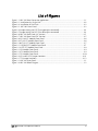
List of Figures
Figure 1-1 ARC-101 Rate Conversion Application ......................................................................... 1-1
Figure 2-1 Installation of a Single Unit .......................................................................................... 2-2
Figure 2-2 Installation of Two Units.............................................................................................. 2-3
Figure 2-3 ARC-101 Front Panel................................................................................................... 2-3
Figure 2-4 Jumper Settings for DTE (Two upper pins connected) ................................................... 2-4
Figure 2-5 Jumper Settings for DCE (Two lower pins connected) ................................................... 2-4
Figure 2-6 ARC-101 Rear Panel (AC Version) ................................................................................ 2-5
Figure 2-7 ARC-101 Rear Panel (DC Version) ................................................................................ 2-5
Figure 2-8 SC13M/155 Module Front Panel .................................................................................. 2-6
Figure 2-9 ST13S/155 Module Front Panel .................................................................................... 2-6
Figure 2-10 ST13L/155 Module Front Panel .................................................................................. 2-7
Figure 2-11 CX/BNC/155 Module Front Panel............................................................................... 2-7
Figure 2-12 UTP/155 Module Front Panel..................................................................................... 2-8
Figure 2-13 E3 Module Front Panel............................................................................................... 2-9
Figure 2-14 T3 Module Front Panel............................................................................................... 2-9
Figure 2-15 E1 Module Front Panel............................................................................................. 2-10
Figure 2-16 E1 and E1/LTU Jumper Locations.............................................................................. 2-12
Figure 2-17 T3 Jumper Locations................................................................................................. 2-13
Figure 3-1 ARC-101 Front Panel.................................................................................................... 3-1
Figure 3-2 ARC-101 Block Diagram.............................................................................................. . 3-3
ARC-101 Installation and Operation Manual
iii
List of Tables
List of Tables
Table 1-1 Optical Module Characteristics....................................................................................... 1-5
Table 1-2 Electrical Module Characteristics .................................................................................... 1-5
Table 3-1 ARC-101 LED Indicators................................................................................................. 3-1
iv
ARC-101 Installation and Operation Manual
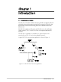
Chapter 1
Introduction
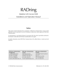
1.1 General Description
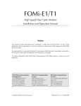
The ARC-101, ATM Rate & Media Converter, provides transparent ATM rate
and media conversion between two interfaces by extracting ATM cells from
one interface at one rate and sending them over a different interface at a
different rate.
The ARC-101 supports a wide variety of ATM data rates and media types.
These include: E1, E3, T3 and STS-3c/STM-1, over optical and electrical
interfaces.
The ARC-101 is supplied as a standalone unit. Special hardware for
mounting the unit in a 19" rack can be ordered separately.
A typical ARC-101 rate conversion application is shown in Figure 1-1.
Figure 1-1 ARC-101 Rate Conversion Application
ARC-101 Features
1-1
ARC-101 Installation & Operation Manual
Chapter 1. Introduction
1.2 ARC-101 Features
This section provides a brief description of the ARC-101's main features.
Interfaces
Supported
The ARC-101 supports a wide variety of ATM data rates and media types,
both electrical and optical.
The electrical interfaces supported are:
•
2 Mbps E1 over Coax/UTP
•
34 Mbps E3 over Coax
•
45 Mbps T3 over Coax
•
155 Mbps STS-3c/STM-1 over Coax
•
155 Mbps STS-3c/STM-1 over Cat-5 UTP
The optical interfaces supported are: Multimode, Single Mode LEDs and
LASERs and 155 Mbps STM-1/STS-3c.
Multiple connector types are available for both electrical and optical
interfaces.
Rate Adaptation
A large internal FIFO is used for rate adaptation between the two interfaces
and for handling the bursty nature of the ATM traffic. Special circuitry is
responsible for closing the ATM flow control loop, according to Available
Bit Rate (ABR) traffic management specifications, in order to avoid FIFO
overflow.
Easy Migration
The modular software-based design of the ARC-101 enables easy migration
to new ATM physical interfaces.
User
Management
and Monitoring
Built-in diagnostics, configuration and statistics are provided via an ASCII
terminal connected to the RS-232 CONTROL port.
Indicators
LED indicators provide information on ARC-101 general status (power and
self-test), as well as left and right link status (ATM activity and link
synchronization).
Compatibility
The ARC-101 complies with ATM Forum specifications.
1-2
ARC-101 Features
ARC-101 Installation & Operation Manual
Traffic
Management
Chapter 1. Introduction
ATM cells are transferred from one interface to the other through an
internal bus, the bandwidth of which is 180 Mbps.
•
•
•
•
Cells that are received with a multiple-bit HEC error are dropped.
Cells received at the slower interface are transferred directly to the other
interface.
Cells received at the faster interface are transferred through the FIFO
which absorbs temporary bursts of ATM cells and transfers them
according to the other interface data rate.
The FIFO depth is 6K cells in SONET/SDH interfaces and 3K cells in other
interfaces.
The ARC-101 implements a single priority queue FIFO. Special circuitry is
responsible for the traffic management and for avoiding FIFO overflow.
•
•
•
•
•
•
•
Loopback Mode
The total bandwidth of CBR cells cannot exceed the slow interface
bandwidth.
The total bandwidth of VBR cells can only temporarily exceed the slow
interface data rate. If this bandwidth is exceeded, cells are queued in
FIFO and are transferred according to the slow interface data rate.
The ARC-101 has a configurable congestion threshold (limit) used to
handle UBR/ABR traffic. You can configure the threshold to be 25%, 50%,
75%, 90% or 100% of the total FIFO depth.
In order to control the UBR/ABR traffic bandwidth, you can configure the
ARC-101 for EFCI marking of cells that are received while the FIFO is
congested, or configure AAL5 Early Packet Discard mode in which a
whole frame is dropped in case of congestion, except for the last cell.
You can configure the ARC-101 to discard cells whose CLP bit is set,
when FIFO is congested.
The number of cells from a certain VP/VC is limited to 3/4 of the total
queue depth, in order to minimize the effects of large bursts of data from
one VC on the other VCs in the ARC-101.
The ARC-101 recalculates the HEC field of cells whose EFCI bit was
changed.
Each ARC-101 interface can be separately configured for Remote or
Internal Loopback mode. The Remote Loopback mode enables a loopback
of the incoming data and clock to the transmit data and clock outputs. The
Internal Loopback mode enables a loopback of the transmitted data to the
received data. Remote Loopback is not available in the E1 interface.
ARC-101 Features
1-3
ARC-101 Installation & Operation Manual
Chapter 1. Introduction
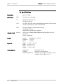
1.3 Specifications
Up to 155 Mbps
Data Rate
Indicators
Control Port
PWR
ON when unit is powered
FLT
BLINKS when self-test fails
(ON during self-test)
ATM
ON when ATM cells were transmitted and received in the last second
and no uncorrected HEC errors were detected.
SYNC
ON when the port is synchronized (no alarm)
OFF during local alarm
BLINKS during remote alarm reception
Interface
RS-232/V.24 at 9600/19200/38400 baud (configurable) with RJ-45
connector.
Default - 9600 baud.
Power
Voltage
Frequency
Power
Physical
Height
4.4 cm / 1.8 in (1U)
Width 21.6 cm / 8.5 in
Depth 29.8 cm / 11.7 in
Weight 1.1 kg / 2.8 lb
Environment
Temperature
Humidity
Radiation Suppression
1-4
Specifications
90-260 VAC or -48 VDC
47-63 Hz
25 Watts
0°-45°C/32°-113°F
Up to 90%, non-condensing
Complies with FCC part 15, subpart J, Class A
Complies with EN55022, Class A
ARC-101 Installation & Operation Manual
Chapter 1. Introduction
ARC-101/#
ATM Rate Converter
Ordering
# Specify power supply:
AC for 90-260 VAC
DC for - 48 VDC
ARC-M/@
Interface module for ARC-101
@ Specify module name - see tables below
RM-1
Hardware for mounting one unit in a 19" rack.
RM-2
Hardware mounting for two units in a 19" rack.
Table 1-1 Optical Module Characteristics
Module
Name
Protocols
Supported
Fiber Type
(Wavelength)
Connector
Type
Dynamic
Range
Optical
Power
(typical)
Sensitivity
SC13M/155
STS-3c
STM-1
62.5/125
(1300 nm)
Duplex SC
16 dB
-18 dBm
-31 dBm
ST13S/155
STS-3c
STM-1
9/125
(1300 nm)
ST (LED)
16 dB
-18 dBm
-31 dBm
ST13L/155
STS-3c
STM-1
9/125
(1300 nm)
ST (LASER)
16 dB
-12 dBm
-31 dBm
Table 1-2 Electrical Module Characteristics
Module
Name
Protocols
Supported
Cable
Type
Connector
Type
Range/Budget
Coding
Method
Impedance
(Ohms)
UTP/155
STS-3c
STM-1
UTP Cat 5
Shielded
RJ-45
100 m
NRZ
100
CX/BNC/155
STS-3c
STM-1
Coax
BNC
12.7 dB*
CMI
75
T3
T3
Coax
BNC
150 m
B3ZS
75
E3
E3
Coax
BNC
150 m
HDB3
75
E1
E1
Coax (UTP)
BNC (RJ-45)
12 dB
HDB3
75 (120)
E1/LTU
E1
Coax (UTP)
BNC (RJ-45)
12 dB
HDB3
75 (120)
* At 78 MHZ, according to the square root of the frequency law.
Specifications
1-5
Chapter 1. Introduction
1-6
Specifications
ARC-101 Installation & Operation Manual
Chapter 2
Installation
This chapter contains mechanical and electrical installation procedures for
connecting the ARC-101 to the main power supply, as well as cabling the
ATM links and monitor (control) port.
2.1 General
The ARC-101 is delivered completely assembled for bench-top installation.
The ARC-101 may be optionally installed in a 19" rack (refer to Section 2.4).
2.2 Unpacking
•
•
•
•
Site Requirements
Inspect the equipment container before unpacking. Note and report
evidence of damage immediately.
Place the container on a clean flat surface. Cut all straps and open, or
remove top.
Remove the unit carefully and place it securely on a clean surface.
Remove all packing material and inspect the unit for damage. Report any
damage immediately.
2-1
ARC-101 Installation & Operation Manual
Chapter 2. Installation
2.3 Site Requirements
Power
The ARC-101 is powered by 90/260 VAC or -48 VDC.
The unit should be installed within 1.5 meters (5 ft.) of an easily accessible
grounded AC outlet capable of supplying the appropriate voltage
(90/260 VAC).
Front and Rear
Panel Clearance
Allow at least 90 cm (36 inches) of clearance at the front of the unit for
operator access. Allow at least 10 cm (4 inches) clearance at the rear of the
unit for power cord connection.
Ambient
Requirements
The ambient operating temperature of the ARC-101 should be 0°C to 45°C
(32°F-113°F), at a relative humidity of up to 90% non-condensing.
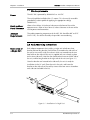
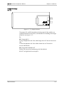
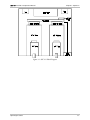
2.4 Rack Mounting Instructions
Installation of
a Single Unit
Rack adapter components for installing a single unit include one short
bracket and one long bracket. Each bracket is fastened to the side walls of
the unit by two screws (with flat washers) which are inserted into the two
front holes on the side wall (the unit is supplied with nuts already in place
on the inner side wall). Note that the short bracket fastens to the left side of
the unit, and the long bracket to the right side of the unit (see Figure 2-1).
Once the brackets are fastened to the side walls, the unit is ready for
installation in the 19" rack. Place the unit in the rack, and fasten the
brackets to the side rails of the rack by means of the two screws situated on
each side (not included in the kit).
Figure 2-1 Installation of a Single Unit
2-2
Rack Mounting Instructions
ARC-101 Installation & Operation Manual
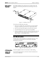
Installation of
Two Units
Chapter 2. Installation
Rack adapter components for installing two units include two short side
brackets (for rack mounting) and two flat rails (for fastening the two units
together)
Figure 2-2 Installation of Two Units
To install two units follow these instructions:
1.
Place two units side by side. On the top of each unit are four grooves.
The grooves should line up when the units are placed side by side.
2.
Place a flat rail on each of the groves in the center of the two units.
3.
Fasten the brackets to the units using the 8 screws provided.
4.
Place the assembled units in the rack, and fasten the brackets to the side
rails of the rack, by means of the two screws situated on each side, as
shown in Figure 2.2 (not included in the kit).
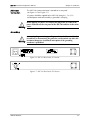
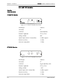
2.5 Cable Connections
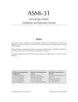
The ARC-101 has several connectors on its front panel (see Figure 2-3) for
ATM connection and connection to an ASCII terminal, and a power
connector on its rear panel.
°°
Figure 2-3 ARC-101 Front Panel
ATM Connection
Connect the appropriate cables to the connectors in both modules.
Control Port
Connection
The CONTROL port connector is an RS-232/V.24 RJ-45 connector for an
ASCII terminal (9600 baud).
Cable Connections
2-3
ARC-101 Installation & Operation Manual
Chapter 2. Installation
When the ARC-101 is used as a DCE or as a DTE, the RJ-45 pinout is:
Pinout
DCE
DTE
Pin 1
Pin 2
Pin 3
DTR
Pin 4
GND
GND
Pin 5
TX Data
RX Data
Pin 6
RX Data
TX Data
Pin 7
CTS
Pin 8
Pin 9
Changing
Control Port Mode
RTS
The ARC-101 is shipped as a DCE. To connect the ARC-101 to a MODEM,
the control port mode must be configured to DTE.
To change the control port mode from DCE to DTE, or vice versa:
1.
Turn the unit OFF (disconnect the power cord).
2.
Unscrew the twelve box cover screws and remove the box cover. The
12 pin DCE/DTE jumper is located on the left side of the ARC-101
mother board when viewed from the rear panel (see Figure 3-2).
3.
To change the configuration to:
•
•
4.
DTE, place the 12 pin jumper on the upper 12 pins.
DCE, place the 12 pin jumper on the lower 12 pins.
Replace the box cover and tighten the screws.
Figure 2-4 Jumper Settings for DTE
(Two upper pins connected)
Figure 2-5 Jumper Settings for DCE
(Two lower pins connected)
2-4
Cable Connections
ARC-101 Installation & Operation Manual
AC Power
Connection
Chapter 2. Installation
The ARC-101's power connector is located on its rear panel
(see Figures 2-6 and Figure 2-7).
AC power should be supplied to the ARC-101 through a 1.5 m (5 ft.)
standard power cord terminated by a grounded 3-wire plug.
Warning
When applying AC power, first connect the plug of the AC cable to the
power connector on the rear panel of the ARC-101 and then to the mains
outlet.
Grounding
Warning
Interrupting the protective (grounding) conductor (inside or outside the
instrument) or disconnecting the protective earth terminal can make this
instrument dangerous. Intentional interruption of the grounding
conductor is prohibited.
Figure 2-6 ARC-101 Rear Panel (AC Version)
Figure 2-7 ARC-101 Rear Panel (DC Version)
ARC-101 Modules
2-5
ARC-101 Installation & Operation Manual
Chapter 2. Installation
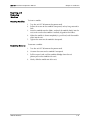
2.6 ARC-101 Modules
Module
Characteristics
SC13M/155 Module
Figure 2-8 SC13M/155 Module Front Panel
Wavelength:
1300 nm
Connector:
SC
Used with:
Multimode fiber
Protocols supported:
STS-3c, STM-1
Coding method:
NRZ
Optical output into 62.5 micron fiber:
-18 dBm (typical)
Receiver sensitivity:
-31 dBm
Maximum input power:
-15 dBm
ST13S/155 Module
TX
RX
AT M
SY N C
ST 1 3S/1 55
Figure 2-9 ST13S/155 Module Front Panel
Wavelength:
1300 nm
Connector:
ST
Used with:
Single mode fiber (LED)
Protocols supported:
STS-3c, STM-1
Coding method:
2-6
NRZ
Optical output into 9 micron fiber:
-18 dBm (typical)
Receiver sensitivity:
-31 dBm
Maximum Input Power:
-15 dBm
ARC-101 Modules
ARC-101 Installation & Operation Manual
Chapter 2. Installation
ST13L/155 Module
Figure 2-10 ST13L/155 Module Front Panel
Wavelength:
1300 nm
Connector:
ST
Used with:
Single mode fiber (LASER)
Protocols supported:
STS-3c, STM-1
Coding method:
NRZ
Optical output into 9 micron fiber:
-12 dBm (typical)
Receiver sensitivity:
-31 dBm
Maximum Input Power:
-15 dBm
CX/BNC/155 Module
Figure 2-11 CX/BNC/155 Module Front Panel
Connector:
BNC
Used with:
Coax cable
Protocols supported:
STS-3c, STM-1
Coding method:
CMI
Budget:
12.7 dB*
Impedance:
75 Ω
Transmit levels:
1v +/- 0.1v P-P
*At 78 MHZ, according to the square root of frequency law.
ARC-101 Modules
2-7
ARC-101 Installation & Operation Manual
Chapter 2. Installation
UTP/155 Module
Figure 2-12 UTP/155 Module Front Panel
Connector:
Shielded RJ-45
Used with:
UTP Cat 5
Protocols supported:
STS-3c, STM-1
Coding method:
NRZ
Range:
100 m
Impedance:
100 Ω
Transmit levels:
1v +/- 0.06v
Pinout
Pin 1
Tx+
Pin 2
Tx-
Pin 3
Pin 4
Pin 5
Pin 6
2-8
Pin 7
Rx+
Pin 8
Rx-
ARC-101 Modules
ARC-101 Installation & Operation Manual
Chapter 2. Installation
E3 Module
Figure 2-13 E3 Module Front Panel
T3 Module
Connector:
BNC
Used with:
Coax cable
Protocols supported:
E3
Coding method:
HDB3
Range:
150 m
Impedance:
75 Ω
Transmit
1v +/- 0.06v
The transmit pulse shape can be determined by jumpers on the module
(refer to Jumper Settings for E1 & E1/LTU).
Figure 2-14 T3 Module Front Panel
ARC-101 Modules
Connector:
BNC
Used with:
Coax cable
Protocols supported:
DS3
Coding method:
B3ZS
Range:
150 m
Impedance:
75 Ω
2-9
ARC-101 Installation & Operation Manual
Chapter 2. Installation
E1 and E1/LTU
Modules
The E1 link interface (Coax/UTP), as well as RX/TX ground reference, can be
determined by jumpers on the module (see Figure 2-16).
Figure 2-15 E1 Module Front Panel
2-10
Connector:
BNC (RJ-45)
Used with:
Coax (UTP)
Protocols supported:
E1
Coding method:
HDB3
Impedance:
75 Ω (120 Ω)
Receive level (with LTU):
0 to -34 dB
Receive level (without LTU):
0 to -12 dB
Transmit level balanced:
3v ± 10%
Transmit level unbalanced:
2.37v ± 10%
ARC-101 Modules
ARC-101 Installation & Operation Manual
Chapter 2. Installation
Inserting and
Removing
Modules
Inserting Modules
To insert a module:
1.
2.
3.
4.
5.
Removing Modules
ARC-101 Modules
Turn the unit OFF (disconnect the power cord).
Pull on the screws on the module's front panel, so they hang outwards a
little.
Insert the module onto the sliders, and push the module slowly into the
unit (make sure that the module is correctly aligned on the sliders).
When the module is almost completely in, push hard, until the module
clicks into the unit.
Tighten the screws on the module's front panel.
To remove a module:
1.
Turn the unit OFF (disconnect the power cord).
2.
Unscrew the screws on the module's front panel.
3.
Pull the screws hard, until the module dislodges from the unit
(please pull out the module with care!)
4.
Slowly slide the module out of the unit.
2-11
ARC-101 Installation & Operation Manual
Chapter 2. Installation
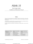
Jumper Settings
for E1 and E1/LTU
The jumpers JP5, JP6, JP10, JP11 and JP13 are used to select the link
interface (Coax or UTP). See Figure 2-16.
Figure 2-16 E1 and E1/LTU Jumper Locations
Note
Turn the module upside down in order to see and move the jumpers.
•
JP5, JP6: Designated BAL/UNBAL.
BAL (up) for operation in Balanced mode (UTP).
UNBAL (down) for operation in Unbalanced mode (Coax, default).
•
•
•
JP10: Place the jumper to connect the BNC shield or RJ-45 screen on the
TX side to earth (recommended for unbalanced mode)
JP11: Place the jumper to connect the BNC shield or RJ-45 screen on the
RX side to earth (recommended for balanced mode).
JP13: Designate BAL/UNBAL.
Position 1 for Unbalanced mode with E1 module.
Position 3 for Balanced mode with E1 module.
Position 4 for Balanced mode with E1/LTU module.
Position 4 for Unbalanced mode with E1/LTU module.
2-12
ARC-101 Modules
ARC-101 Installation & Operation Manual
Chapter 2. Installation
Jumper Settings
for T3
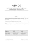
Figure 2-17 T3 Jumper Locations
The jumpers JP1 and JP2 (located near the front panel of the module), are
used to control the transmit levels, and should be set according to the length
of the links (see Figure 2-17).
T3:
JP1: Designated L/S
L (Long) for operation with Coax cables longer than 225 feet on the transmit
side
S (Short) for operation with Coax cables shorter than 225 feet on the
transmit side (default)
JP2: Designated NORM/BOOST
NORM: For transmit level conforming ANSI.102 (default)
BOOST: For higher level transmit pulse
ARC-101 Modules
2-13
Chapter 2. Installation
2-14
ARC-101 Installation & Operation Manual
ARC-101 Modules
Chapter 3
Operation
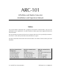
The ARC-101 has several LED indicators, providing information on the
ARC-101's general status, as well as right and left module status
(see Figure 3-1). The indicators are ON, OFF, or BLINK, depending on the
state of ARC-101. Table 3-1 lists the functions of the front panel indicators.
out out out
Figure 3-1 ARC-101 Front Panel
Table 3-1 ARC-101 LED Indicators
Name
Description
PWR (green)
ON
When ARC 101 is powered.
FLT (red)
BLINKS
Error detected during self-test
ON
− If the error is in one of the modules, the module's two LEDs blink;
− In case of a system error, the two module's LEDs blink.
During self-test
ATM (green)
ON
During active ATM connections on the module's port:
That is when no HEC error was detected during the last second and,
at least one cell was received and transmitted in the last second.
SYNC (green)
ON
OFF
BLINKS
When the module's port is synchronized (no alarm)
During local alarm (a fault is detected on the receive side of ARC-101).
During remote alarm the remote unit signals that a fault has been
detected.
Operating Procedure
3-1
ARC-101 Installation & Operation Manual
Chapter 3. Operation
3.1 Operating Procedure
Note
Turning on the
ARC-101
The interface modules are not hot-swappable. If you install or change
modules, make sure to first disconnect power to the ARC-101, and then
remove/install modules slowly and carefully (so as not to damage the modules
or the ARC-101 enclosure). See section 2.6.
Install the ARC-101 as described in Chapter 2. Make sure that the power
cord is connected to the ARC-101's power connector on the rear panel.
Plug the other end of the power cord into the mains outlet. The PWR
indicator on the front panel should light.
Upon power-up, the ARC-101 goes through a self-test that takes about
40 seconds to complete. The FLT indicator is ON during the self-test. After
the self-test is completed, if no faults have been detected, the FLT indicator
is OFF. Detailed test results can e viewed from an ASCII terminal
connected to the ARC-101's CONTROL port.
Normal
Operation
The ARC-101 operates unattended. During normal operation, the PWR
indicators should light continuously, the FLT indicator should be OFF, the
ATM indicator should light up when ATM traffic passes through the
module, and the SYNC indicator should light up continuously.
Turning off the
ARC-101
To turn off the ARC-101, disconnect the power cord from the mains outlet.
Procedure in
Case of
Malfunctioning
The following table lists several common problems and their possible
solutions.
The PWR LED does not light up
Fault (FLT) LED blinks
Data transmission difficulties
−
Check the power cord connection on the back of the unit and at the
mains outlet.
−
Verify power availability at the mains outlet.
−
Unplug the unit (power OFF). Make sure that the modules are inserted
properly. Tighten the modules' screws. Power ON the unit.
−
Using an ASCII terminal port, check for a fault indication in the
Diagnostics window. If there is a fault, inform a qualified ARC-101
technician.
−
Ensure that the plugged-in modules are compatible with the protocol
used (media, data rate).
Check the module's software configuration in the Configuration window.
Verify that the SYNC indicator is ON. If it is OFF (indicating a fault in the
data reception link), run diagnostics on the remote unit from which data
is being transmitted to the ARC-101. If it is BLINKING (indicating a fault
in the data transmission link), run diagnostics on the remote unit, or
implement a loop on the ARC-101 module, and verify that the
SYNC LED is ON.
−
−
3-2
Operating Procedure
ARC-101 Installation & Operation Manual
Chapter 3. Operation
Figure 3-2 ARC-101 Block Diagram
Operating Procedure
3-3
Chapter 3. Operation
3-4
ARC-101 Installation & Operation Manual
Operating Procedure
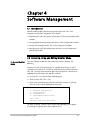
Chapter 4
Software Management
4.1 Introduction
Monitor mode enables software management of the ARC-101. Four
categories of software management are available:
•
•
•
•
Monitoring the ARC-101 general information via the General Information
window.
Changing default configuration parameters via the Configuration window.
Testing and resetting the ARC-101 via the Diagnostics window.
Monitoring the ARC-101 performance and status via the Performance
Monitoring window.
4.2 Accessing, Using and Exiting Monitor Mode
To Access Monitor
Mode
To access Monitor mode from the supervisory terminal, perform the
following:
Connect an ASCII ANSI terminal or a PC capable of emulating an ASCII
ANSI terminal to the RJ-45 CONTROL connector on the front panel of the
ARC-101. Terminal communication port setup should have a baud rate of
9600 bps, 8 bits/character, one stop bit, no parity.
•
•
•
If using a PC, run a terminal emulation program.
Make sure the ARC-101 is ON.
After a few seconds (during which the ARC-101 executes its self-test),
the main menu will be displayed on the screen.
ARC MENU
1.
2.
3.
4.
General Information
Configuration
Diagnostics
Performance Monitoring
ESC. Exit
Choose item from the menu:
To select an option, select the item number corresponding to the option.
If no change is required, press the Escape key (Esc).
Accessing, Using and Exiting Monitor Mode
4-1
ARC-101 Installation & Operation Manual
Chapter 4. Software Management
4.3 Screen Explanations
Each of the screens shown below is followed by a detailed explanation of the
parameters and options appearing in the screen.
•
•
The acceptable value range for each parameter, where applicable, is
shown in parentheses – "( )".
The default value for each parameter, where applicable, appears in the
screens.
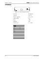
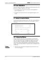
4.4 General Information Window
To view general information about the ARC-101, such as software/hardware
versions, basic configuration and self-test results, select option 1 from the
main menu.
GENERAL INFORMATION
Software Version:
0.0
Hardware Version:
0.0
ATM Rate Converter Configuration:
Self-Test ended successfully
E1
over
STM-1
to
UTP/COAX
over
FIBER
4.5 Configuration Window
Default configuration parameters can be changed via the Configuration
window. To enter the Configuration window, select oprtion 2 in the main
menu. The Configuration screen is divided into 6 submenus/commands:
System Parameters, Left Module parameters, Right Module parameters,
ASCII Terminal Configuration parameters, Set Default Parameters and Save
Changes. Note that some parameters are general while some depend on the
module type.
To Set a
Parameter:
4-2
•
Select the item number which corresponds to the parameter that you
want to view/configure.
Configuration Window
ARC-101 Installation & Operation Manual
Chapter 4. Software Management
To Save the Configuration:
CONFIGURATION
1.
2.
3.
4.
5.
6.
System Parameters
Left Module
Right Module
ASCII Terminal Configuration
Set Default Parameters
Save Changes
ESC. Exit
•
After making all changes, return to the Configuration window, and select
option 6. If a new value was entered at any menu, the following prompt
will appear upon exiting the menu:
ALL CHANGES WILL BE SAVED. ARE YOU SURE? (Y/N)
•
Note
To Set Default
Parameters
Note
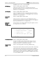
System
Parameters
Type Y for "Yes", or press any other key for "No".
If you change a module, the ARC-101 will reboot with its default parameters.
To return all configuration parameters to their factory defaults, go to the
Configuration window, and select option 5.
If you set the Default Parameters, the Baud Rate parameter will be changed
and saved as 9600. The ASCII Terminal Baud will be changed to 9600 the next
time the ARC is restarted.
To set system parameters, select option 1 from the Configuration menu.
SYSTEM PARAMETERS
1. FIFO Congestion Threshold: 90%
2. EFCI Marking:
Disable
3. CLP Dropping:
Disable
4. Early Packet Discard:
Disable
ESC. Exit
Select item from the menu:
FIFO Congestion
Threshold
(Default - 75%); options: 25%, 50%, 75%, 90%, 100%
The FIFO threshold in which the ARC-101 will enter the "congestion" state
Configuration Window
4-3
ARC-101 Installation & Operation Manual
Chapter 4. Software Management
The options are 25%, 50%, 75%, 90% and 100%.
EFCI Marking
(Default - Disable); options: Enable, Disable
Enables EFCI marking while FIFO is in congested state. Setting this
parameter to Enable causes the EFCI marking of all cells that are received,
while FIFO is in a congested state.
CLP Dropping
(Default - Disable); options: Enable, Disable
Enables CLP dropping when FIFO is congested. Setting this parameter to
Enable causes cells - with CLP bit set - to be dropped, if they are received
while FIFO is in a congested state.
Early Packet
Discard
(Default - Disable); options: Enable, Disable
Enables entire frame, except for last cell, to be dropped when FIFO is
congested. Setting this parameter to Enable causes frames to be dropped, if
they are received while FIFO is in a congested state.
Right/Left
Module
Configuration
The two windows (Left and Right module configuration, options 2 and 3 in
the Configuration menu) are identical.
LEFT MODULE
1. Port Enable/Disable:
Enable
2. Transmit Clock Source:
3. Loopback State:
Loopback
Disable
4. SONET/SDH Frame Type: STM-1 (SDH)
ESC. Exit
Port Enable/Disable (Default - Enable); options: Enable, Disable
If the port is Disabled, no data will be received at the port. Transmit
functions are not changed. Remote loop is still available. If the port is
Enabled, received data is transferred to the other port.
Transmit Clock
Source
(Default - Local timing); options: Local timing, Loopback timing
This parameter selects the clock source for the transmit clock. "Local timing"
selects the clock that is derived from the oscillator on board. "Loopback
timing" selects the clock recovered from the received data to be the source.
Note that for an E1 interface, the default is "Loopback timing" and should
not be changed. Do not configure the module for Loopback timing while it
is in Internal Loopback mode.
4-4
Configuration Window
ARC-101 Installation & Operation Manual
Loopback State
Chapter 4. Software Management
(Default - Disable); options: Disable, Remote, Internal
Setting this parameter to Remote will cause a loopback of the incoming
data and clock to the transmit data and clock (this option is not supported
with E1). Internal Loopback will cause a loopback of the transmitted data to
the receive port.
SONET/SDH Frame
Type
(Default - STM-1); options: STS-3c, STM-1
This parameter is only used in 155 Mbps cards. It defines the Frame Type
to be STS-3c (SONET) or STM-1 (SDH).
DS3 Mapping
(Default - Direct); options: Direct, PLCP-Ext' 8Kclk, PLCP-Int' 8Kclk
This parameter is only used in T3 card. It selects the DS3 mapping and the
PLCP clock, in case of PLCP mapping. Direct mode is the HEC mapping
mode. PLCP mapping with Internal 8Kclk forces the transmit PLCP to be
synchronized to an on-board clock. PLCP with External 8Kclk uses the
received PLCP clock as a reference.
ASCII Terminal
Configuration
To set ASCII terminal parameters, select option 4 from the Configuration
menu.
ASCII TERMINAL CONFIGURATION
1. Display Mode:
Color
2. Baud Rate:
9600 Kbps
ESC. Exit
Select item from the menu:
Note
When you change the module's baud rate, you will lose communication with
the module, until you adjust the baud rate of ASCII terminal or PC to match
the baud rate of the module.
The default display mode is Color. The default baud rate is 9600.
To change the baud rate:
Configuration Window
1.
Set the required baud rate on the ARC-101 monitor (option 2 in the
ASCII terminal configuration window).
2.
Press the Escape key (ESC).
3.
Change the ASCII terminal baud rate.
4.
A "Press ESC" message will appear on the monitor while synchronization
is achieved.
4-5
ARC-101 Installation & Operation Manual
Chapter 4. Software Management
4.6 Diagnostics Window
The ARC-101 can be tested and reset via the Diagnostics window. To enter
the Diagnostics window, select item number 3 in the main menu.
The Diagnostics window includes the following options:
•
General Reset
•
Modules Reset & Self-test
•
Last Self-Test Results
•
Self-test results are displayed on-screen.
DIAGNOSTICS
1. General Reset
2. Module Reset & Self-Test
3. Last Self-Test Results
ESC. Exit
Select item from the menu:
General Reset
This mode enables a full test of the ARC-101. This self-test enables
checking the modules and system card, in addition to the tests performed
during the right/left module self-tests.
Modules Reset
and Self-Test
A self-test can be performed on the ARC-101's modules, including the
testing of the ATM interfaces and PHY cards.
Last Self-Test
Results
This option is used to monitor the self-test results.
4.7 Performance Monitoring Window
ARC-101 performance and status can be viewed via the Performance
Monitoring window. To enter the Performance Monitoring window, select
item number 4 in the main menu. The window provides an option to reset
the counters and includes two windows:
4-6
Performance Monitoring Window
ARC-101 Installation & Operation Manual
Chapter 4. Software Management
•
Link Status
•
ATM Status
PERFORMANCE MONITORING
1. Link Status
2. ATM Status
3. Reset Counters
ESC. Exit
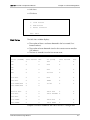
The Link Status window displays:
Link Status
•
•
•
The number of alarms and errors detected in the last second ("Last
Second" column).
The number of errors detected since the last counter reset or overflow
("All" column).
The time (in seconds) since the last counter reset.
Link Status
STS-3C (FIBER)
Last Second
ALL
T3 (Coax)
Last Second
ALL
LOS
0
0
LOS
0
0
LOF
0
0
OOF
0
0
LOC
0
0
AIS
0
0
SLM
0
0
Yellow
0
0
Line AIS
0
0
BIP
0
0
Path AIS
0
0
FEBE
0
0
Line FERF/RDI
0
0
P1/P2
0
0
Path FERF/RDI
0
0
Section BIP
0
0
PLCP LOF
0
0
Line BIP
0
0
PLCP YELLOW
0
0
Path BIP
0
0
Line FEBE
0
0
PLCP BIP
0
0
Path FEBE
0
0
PLCP FEBE
0
0
LOP
Example: Link Status window for ARC-101 in SONET-T3 configuration
Performance Monitoring Window
4-7
ARC-101 Installation & Operation Manual
Chapter 4. Software Management
SONET/SDH Link Status Window
LOS
Loss of Signal
LOF
Loss of Frame
LOP
Loss of Pointer
LOC
Loss of Cell Delineation
SLM
Signal Cable Mismatch
Line AIS
Line Alarm Indication Signal
Path AIS
Path Alarm Indication Signal
Line FERF/RDI
Line Far End Receive Failure/Remote Defect Indicator
Path FERF/RDI
Path Far End Receive Failure/Remote Defect Indicator
A '0'' in the "Last Sec" columns of the Alarms listed above, indicates that no errors have occurred. A '1' in the
"Last Sec." column indicates that there are one or more errors in the last second. The number in the "All"
column is equal to the cumulative number of seconds in which errors occurred.
Section BIP
Section Bit Interleaved Parity
Line BIP
Line Bit Interleaved Parity
Path BIP
Path Bit Interleaved Parity
Line FEBE
Line Far End Block Error
Path FEBE
Path Far End Block Error
T3 Link Status Window - Errors/Alarms displayed in Direct (HEC) Mode
LOS
Loss of Signal
OOF
Out of Frame
LOC
Loss of Cell Delineation
AIS
Alarm Indication Signal
Yellow
Yellow Alarm
A '0'' in the "Last Sec" columns of the Alarms listed above, indicates that no errors have occurred. A '1' in the
"Last Sec." column indicates that there are one or more errors in the last second.
BIP
Bit Interleaved Parity
FEBE
Far End Block Error
P1/P2
P1/P2
4-8
Performance Monitoring Window
ARC-101 Installation & Operation Manual
Chapter 4. Software Management
T3 Link Status Window - Errors/Alarms displayed in PLCP Mode
LOS
Loss of Signal
OOF
Out of Frame
AIS
Alarm Indication Signal
Yellow
Yellow Alarm
PLCP_LOF
PLCP Loss of Frame
PLCP_Yellow
PLCP Yellow
A '0'' in the "Last Sec" columns of the Alarms listed above, indicates that no errors have occurred. A '1' in the
"Last Sec." column indicates that there are one or more errors in the last second. The number in the "All"
column is equal to the cumulative number of seconds in which errors occurred.
BIP
Bit Interleaved Parity
FEBE
Far End Block Error
P1/P2
P1/P2 Parity Error
PLCP_BIP
PLCP Bit Interleaved Parity
PLCP_FEBE
PLCP Far End Block Error
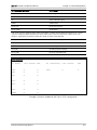
Link Status
E3 (Coax)
last second
ALL
E1 (Coax/UTP)
last second
ALL
LOS:
0
0
LOC:
0
0
OOF:
0
0
LOC
0
0
AIS:
0
0
RDI:
0
0
BIP:
0
0
FEBE:
0
0
Example: Link Status window for ARC-101 in E3-E1 configuration
Performance Monitoring Window
4-9
ARC-101 Installation & Operation Manual
Chapter 4. Software Management
E3 Link Status Window
LOS
Loss of Signal
OOF
Out of Frame
LOC
Loss of Cell Delineation
AIS
Alarm Indication Signal
RDI
Remote Defect Indicator
A '0'' in the "Last Sec" columns of the Alarms listed above, indicates that no errors have occurred. A '1' in the
"Last Sec." column indicates that there are one or more errors in the last second. The number in the "All"
column is equal to the cumulative number of seconds in which errors occurred.
BIP
Bit Interleaved Parity
FEBE
Far End Block Error
E1 Link Status Window
LOC
Loss of Cell Delineation
A '0'' in the "Last Sec" columns of the Alarms listed above, indicates that no errors have occurred. A '1' in the
"Last Sec." column indicates that there are one or more errors in the last second. The number in the "All"
column is equal to the cumulative number of seconds in which errors occurred.
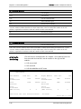
ATM Traffic
Monitoring
ATM cell statistics are displayed in this window - the number of events that
have occurred since counters reset or overflow in the right and left
modules:
•
•
•
Cells transmitted
Cells received
Cells discarded due to HEC errors
ATM STATUS
Left Module
Last Sec.
All
Right Module
Last Sec.
All
Cells
Transmitted:
1200
412000 Cells
Transmitted:
1990
412010
Cells
Received
1208
412020 Cells
Received
1990
412000
0
0
Cells
Discarded:
(HEC errors)
0
0
Time since the last Counters Reset:
Cells
Discarded:
(HEC errors)
00:34:46
Press ESC to exit
4-10
Performance Monitoring Window
ARC-101 Installation & Operation Manual
Note
Chapter 4. Software Management
The Cells Transmitted counter is not valid in Remote Loopback mode, and the
Cells Received counter in not valid in Internal Loopback mode.
The counter precision is 1/10,000.
Performance Monitoring Window
4-11
Chapter 4. Software Management
4-12
ARC-101 Installation & Operation Manual
Performance Monitoring Window