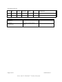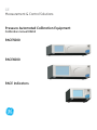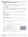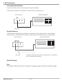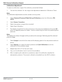
1
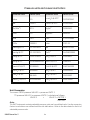
Pressure measurement for research & industry Druck Limited Fir Tree Lane Groby Leicester LE6 0FH England Tel: 0116 231 7100 Pressure Automated Calibration Equipment Calibration manual K0450 Druck Limited 2010 This document is the property of Druck Limited and may not, either in part or whole, be copied or otherwise reproduced, communicated in any way to third parties, nor stored in any data processing system, without the express written authority of Druck Limited. Page 1 of 26 K0450 Issue 2 DO NOT PRINT THIS PAGE Amendment Record Iss No Date C/N No Originator Typed Workflow Amendments No. 1 21/04/10 N/A Robert Lee Robert Lee 144693 New document 2 12/10/10 25591 Robert Lee Robert Lee 152835 Add section 2, PACE1000 details Approvals Engineering P BRADLEY Marketing M SINGLETON Technical Communications R LEE Page 2 of 26 K0450 Issue 2 DO NOT PRINT THIS PAGE Print Instructions Page size 180 x 230 mm. Note: this document is normally published electronically and shipped on UD-0001. THIS HARDCOPY IS NOT TO BE USED AS CAMERA COPY. Page 3 of 26 K0450 Issue 2 DO NOT PRINT THIS PAGE Page 4 of 26 K0450 Issue 2 DO NOT PRINT THIS PAGE GE Measurement & Control Solutions Pressure Automated Calibration Equipment Calibration manual K0450 PACE5000 PACE6000 PACE Indicators g © The General Electric Company. All rights reserved Introduction This technical manual provides calibration instructions for the PACE Pressure Controllers and Indicators. The features shown and described in this manual may not be available on some models. Safety The manufacturer has designed this equipment to be safe when operated using the procedures detailed in this manual. Do not use this equipment for any other purpose than that stated. This publication contains operating and safety instructions that must be followed to ensure safe operation and to maintain the equipment in a safe condition. The safety instructions are either warnings or cautions issued to protect the user and the equipment from injury or damage. Use suitably qualified * calibration technicians and good engineering practice for all procedures in this publication. Pressure Do not apply pressures greater than the maximum working pressure to the equipment. It is the responsibility of the calibration technician to apply pressures within the published pressure range and to only use external pressure equipment with correctly rated fittings and components. Toxic Materials There are no known toxic materials used in construction of this equipment. Maintenance The equipment must be correctly maintained, the manufacturer’s procedures should be carried out by authorized service agents or the manufacturer’s service departments. Technical Advice For technical advice contact the manufacturer. * A qualified calibration technician must have the necessary technical knowledge, documentation, special calibration/test equipment and tools to carry out the required work on this equipment. K0450 Issue No. 2 i Abbreviations The following abbreviations are used in this manual; the abbreviations are the same in the singular and plural. abs Absolute a.c. Alternating current ALT Altitude BSP British pipe thread CAS Calculated airspeed CSK Countersunk d.c. Direct current DPI Digital Pressure Instrument e.g. For example etc. And so on Fig. Figure ft Foot g Gauge Hg Mercury HTS High tensile steel Hz Hertz IAS Indicated airspeed i.e. That is IEC International Electrotechnical Commission IEEE 488 Institute of Electrical and Electronic Engineers standard 488 data in Inch kg Kilogram kts/kn knot LCD Liquid crystal display m Metre mA Milliampere max Maximum mbar Millibar min Minute or minimum mm Millimetre mV Millivolts MWP Maximum working pressure No. Number NPT National Pipe Thread PACE Pressure Automated Calibration Equipment Para. Paragraph PDCR Pressure transducer PED Pressure Equipment Directive psi Pounds per square inch PTX Pressue transmitter K0450 Issue No. 2 ii ROC RS232 RtCAS RtMach SCPI UUT V VFC +ve -ve °C Rate of Climb Serial communications data standard Rate of calculated airspeed Rate of Mach Standard Commands for Programmable Instruments Unit under test Volts Volts-free contact Positive Negative Degrees Celsius Associated publications K0447 PACE5000/6000 User Guide and Safety Instructions K0467 PACE1000 Indicator User Guide and Safety Instructions K0443 PACE5000/6000 Controller User Manual K0470 PACE1000 Indicator User Manual K0476 Pressure Control Module User Guide and Safety Instructions K0472 SCPI Communications Manual K0469 Heritage Communications Manual - Instrument Emulation Symbols The equipment contains the following symbols to identify hazards. This equipment meets the requirements of all relevant European safety directives. The equipment carries the CE mark. This symbol, on the instrument, indicates that the user should refer to the user manual. This symbol, on the instrument, indicates do not throw-away in domestic bin, hazardous material, dispose correctly in accordance with local regulations. K0450 Issue No. 2 iii Pressure units and conversion factors Pressure units Factor (hPa) Pressure units Factor (hPa) mbar 1.0 cmH2O @ 20°C 0.978903642 bar 1000.0 mH2O @ 20°C 97.8903642 Pa (N/m2) 0.01 kg/m2 0.0980665 hPa 1.0 kg/cm2 980.665 kPa 10.0 torr 1.333223684 MPa 10000.0 atm 1013.25 mmHg @ 0°C 1.333223874 psi 68.94757293 cmHg @ 0°C 13.33223874 lb/ft2 0.4788025898 mHg @ 0°C 1333.223874 inH2O @ 4°C 2.4908891 inHg @ 0°C 33.86388640341 inH2O @ 20°C 2.486413 mmH2O @ 4°C 0.0980665 inH20 @ 60°F 2.487641558 cmH2O @ 4°C 0.980665 ftH2O @ 4°C 29.8906692 mH2O @ 4°C 98.0665 ftH2O @ 20°C 29.836983 mmH2O @ 20°C 0.097890364 ftH20 @ 60°F 29.8516987 Unit Conversion To convert FROM pressure VALUE 1 in pressure UNITS 1 TO pressure VALUE 2 in pressure UNITS 2, calculate as follows: VALUE 2 = VALUE 1 x FACTOR 1 FACTOR 2 Note: The PACE instrument contains selectable pressure units and user defined units. Use the conversion factors to calculate a user defined unit from the table above. Refer to the data sheets for the list of selectable pressure units. K0450 Issue No. 2 iv CONTENTS Title Page CALIBRATION PROCEDURES for PACE CONTROLLERS 1-1 Introduction.................................................................................................................... 1-1 Calibration Status ........................................................................................................ 1-1 Preliminary Operations ............................................................................................. 1-1 Connecting the Calibrator ....................................................................................... 1-2 Calibration Check (All Ranges) .............................................................................. 1-3 Calibration Adjustment............................................................................................. 1-5 CALIBRATION PROCEDURES for PACE INDICATORS 2-1 Introduction.................................................................................................................... 2-1 Calibration Status ........................................................................................................ 2-1 Preliminary Operations ............................................................................................. 2-1 Connecting the Calibrator ....................................................................................... 2-2 Calibration Check (All Ranges) .............................................................................. 2-3 Calibration Adjustment............................................................................................. 2-5 K0450 Issue No. 2 v intentionally left blank K0450 Issue No. 2 vi PACE Series Calibration Manual 1 Calibration Procedures for PACE Controllers Introduction The PACE controller incorporates a calibration facility; for the PACE to stay accurate, a calibration check should be carried out at chosen intervals. If the accuracy of the PACE is not within the permissible deviation, carry out a calibration adjustment. Calibration Status Using the Measured Pressure/Instrument Status menu, the calibration status of the calibrator can be displayed on the front panel screen. The status menu includes Calibration History which gives a list of dates of the stored calibration corrections. Note: The Date and Time must be set correctly using the Measured Pressure/Global Set-up/ Calibration menu. Calibration Equipment The original GE Calibration Certificate shows the measurement uncertainty of the original calibration standard. Preliminary Operations Review and become familiar with the whole procedure before beginning a calibration process. Allow at least one hour for the PACE to thermally stabilize in a thermally stable environment after switching on and before calibration. Before starting a calibration procedure: Carry out a leak test as detailed in PACE user manual K0443. Notes on calibration The pressure standard output port and the reference level must be at the correct level or use heightcorrected applied pressure. To prevent applied calibration pressure “back feed”, fit blanking plugs to both positive and negative supply ports on the manifold. Make sure that before starting a calibration procedure both pressures on gauge measurements are equalised and stable. Set the PACE units of pressure to one of the required units for calibration. K0450 Issue No. 2 1-1 1 PACE Controllers Connecting the Calibrator Connect the calibrator for each pressure range as follows: Connect the output of the pressure standard to the PACE module output port. PACE Pressure Standard rear view Gauge Reference If the pressure standard has a reference connection, then connect this to the PACE reference port on the module manifold. Otherwise the calibrator reference port should be open to atmosphere. PACE rear view Pressure Standard module 2 reference port open to atmosphere or to reference port of the pressure standard. Absolute Range Note The PACE adds the barometric reading to a gauge range to produce an absolute range. Calibration Check (All Ranges) Procedure K0450 Issue No. 2 1-2 PACE Series Calibration Manual Set the calibrator to measure mode: 1 Connect calibration standard for the pressure range to be checked. 2 Press Task and select Basic. 3 With the pressure standard connected to the correct pressure port, select Measured Pressure and press Range to select the gauge pressure range to be checked. 4 Barometric pressure can be displayed in the status area. Gauge ranges should be zeroed as follows: 1 Press Measured Pressure/Zero to zero the selected range. 2 On completion of the zero operation, the display shows Zero completed successfully. 3 Adjust calibration pressure to the first pressure value. 4 Compare the pressure value on the calibration standard to the value displayed and record the difference. 5 Repeat (3) and (5) for each pressure. 6 If the recorded difference exceeds the permissible deviation for the selected range, the calibrator requires a calibration adjustment for that range. Refer to sales data sheets SDS0001 and SDS0008 for permissable deviation. 7 Select the next pressure range for a calibration check. 8 After completing all calibration checks, adjust calibration standard to atmospheric pressure. 9 Disconnect calibration standard from the output. If no further calibration is required, switch off the PACE. K0450 Issue No. 2 1-3 1 PACE Controllers K0450 Issue No. 2 1-4 PACE Series Calibration Manual Calibration Adjustment To adjust a calibration range of the calibrator, proceed as follows. 1 Connect the calibrator for the range to be adjusted, as detailed in Calibration Check. Note The calibration adjustments must be carried out in any order. 2 Select Measured Pressure/Global Set-up/Calibration, enter the Calibration PIN (4321). 3 Select Sensor Correction. 4 Select the pressure range to be corrected. 5 Select New Calibration. 6 The display shows the first value to be set on the pressure standard and to press OK when the applied pressure is stable. Use the numeric keys to enter the precise applied pressure. Note The display also shows throughout this procedure the message Calibrating and the selected pressure range. 7 Select Accept to store the first value and the display goes to the next pressure value to be set. 8 Select Repeat to re-apply the same pressure and Quit Calibration to exit the calibration of this pressure range. 9 Repeat steps (5) to (7) for the next value. 10 Carry out a calibration check to verify this procedure. 11 After completing the calibration procedures, adjust the calibration standard to atmospheric pressure. Disconnect calibration standard from the PACE. K0450 Issue No. 2 1-5 1 PACE Controllers K0450 Issue No. 2 1-6 PACE Series Calibration Manual 2 Calibration Procedures for PACE Indicators Introduction The PACE indicator incorporates a calibration facility; for the PACE to stay accurate, a calibration check should be carried out at chosen intervals. If the accuracy of the PACE is not within the permissible deviation, carry out a calibration adjustment. Calibration Status Using the Measured Pressure/Instrument Status menu, the sensor calibration status of the indicator can be displayed on the front panel screen. The status menu includes Calibration History which gives a list of dates of the stored calibration corrections. Note: The Date and Time must be set correctly using the Measured Pressure/Global Set-up/ Calibration menu. Calibration Equipment The original GE Calibration Certificate shows the measurement uncertainty of the original calibration standard. Preliminary Operations Review and become familiar with the whole procedure before beginning a calibration process. Allow at least one hour for the PACE to thermally stabilize in a thermally stable environment after switching on and before calibration. Before starting a calibration procedure: Carry out a leak test as detailed in PACE Indicator user manual K0470. Notes on calibration The pressure standard output port and the indicator reference level must be at the correct level or use height-corrected applied pressure. Make sure that before starting a calibration procedure both pressures on gauge measurements are equalised and stable. Set the PACE units of pressure to one of the required units for calibration. K0450 Issue No. 2 2-1 2 PACE Indicators Connecting the Indicator Connect the indicator for each pressure range as follows: Connect the output of the pressure standard to the indicator port. PACE Indicator Pressure Standard rear view Gauge Reference If the pressure standard has a reference connection, then connect this to the indicator reference port. Otherwise the indicator reference port should be open to atmosphere. PACE Indicator rear view Pressure Standard indicator reference port open to atmosphere or to reference port of the pressure standard. Absolute Range Note The indicator adds the barometric reading to a gauge range to produce an absolute range. K0450 Issue No. 2 2-2 PACE Series Calibration Manual Calibration Check (All Ranges) Procedure Set the indicator to measure mode: 1 Connect calibration standard for the pressure range to be checked. 2 Press Task and select Basic. 3 With the pressure standard connected to the correct pressure port, select Measured Pressure and press Range to select the gauge pressure range to be checked. 4 Barometric pressure can be displayed in the status area. Gauge ranges should be zeroed as follows: 1 Press Measure Pressure/Zero to zero the selected range or press the zero button on the screen. 2 On completion of the zero operation, the display shows Zero completed successfully. 3 Adjust calibration pressure to the first pressure value. 4 Compare the pressure value on the calibration standard to the value displayed and record the difference. 5 Repeat (3) and (5) for each pressure. 6 If the recorded difference exceeds the permissible deviation for the selected range, the indicator requires a calibration adjustment for that range. Refer to the sales data sheet for permissable deviation. 7 Select the next pressure range for a calibration check. 8 After completing all calibration checks, adjust calibration standard to atmospheric pressure. 9 Disconnect calibration standard from the output. If no further calibration is required, switch off the PACE indicator. K0450 Issue No. 2 2-3 2 PACE Indicators K0450 Issue No. 2 2-4 PACE Series Calibration Manual Calibration Adjustment To adjust a calibration range of the indicator, proceed as follows. 1 Connect the indicator for the range to be adjusted, as detailed in Calibration Check. Note The calibration adjustments must be carried out in any order. 2 Select Measured Pressure/Global Set-up/Calibration, enter the Calibration PIN (4321). 3 Select Sensor Correction. 4 Select the pressure range to be corrected. 5 Select New Calibration. 6 The display shows the first value to be set on the pressure standard and to press OK when the applied pressure is stable. Use the numeric keys to enter the precise applied pressure. Note The display also shows throughout this procedure the message Calibrating and the selected pressure range. 7 Select Accept to store the first value and the display goes to the next pressure value to be set. 8 Select Repeat to re-apply the same pressure and Quit Calibration to exit the calibration of this pressure range. 9 Repeat steps (5) to (7) for the next value. 10 Carry out a calibration check to verify this procedure. 11 After completing the calibration procedures, adjust the calibration standard to atmospheric pressure. Disconnect calibration standard from the PACE indicator. K0450 Issue No. 2 2-5 2 PACE Indicators K0450 Issue No. 2 2-6 © The General Electric Company. All rights reserved