1
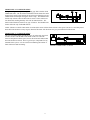
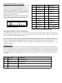
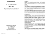
MODELS: PCL352 and PCL353 INDEXERS
and
DPF723352 and DPF73353 DRIVER PACKS
PCL353
DPF73352
ANAHEIM AUTOMATION
910 E. Orangefair Lane
Anaheim, CA 92801
TEL (714) 992-6990
FAX (714) 992-0471
August, 1997
#L010028
COPYRIGHT
Copyright 1993 by Anaheim Automation. All rights reserved. No part of this publication may be reproduced,
transmitted, transcribed, stored in a retrieval system, or translated into any language, in any form or by any means,
electronic, mechanical, magnetic, optical, chemical, manual, or otherwise, without the prior written permission of
Anaheim Automation, 910 E. Orangefair Lane, Anaheim, CA 92801. The only exception to this would be use of the
program examples in this manual.
DISCLAIMER
Though every effort has been made to supply complete and accurate information in this manual, the contents are subject
to change without notice or obligation to inform the buyer. In no event will Anaheim Automation be liable for direct,
indirect, special, incidental, or consequential damages arising out of the use or inability to use the product or
documentation.
LIMITED WARRANTY
All Anaheim Automation products are warranted against defects in workmanship, materials and construction, when
used under Normal Operating Conditions and when used in accordance with specifications. This warranty shall be
in effect for a period of twelve months from the date of purchase or eighteen months from the date of manufacture,
whichever comes first. Warranty provisions may be voided if the products are subjected to physical damage or abuse.
Anaheim Automation will repair or replace at its option, any of its products which have been found to be defective and
are within the warranty period, provided that the item is shipped freight prepaid, with RMA (return material
authorization), to Anaheim Automation's plant in Anaheim, California.
TRADEMARKS
Control Link and Driver Pack are registered trademarks of Anaheim Automation.
IBM PC is a registered trademark of International Business Machines, Inc.
TABLE OF CONTENTS
Page
Introduction . . . . . . . . . . . . . . . . . . . . . . . . . . 1
Description . . . . . . . . . . . . . . . . . . . 1
Ordering Information . . . . . . . . . . . 2
Speed Considerations . . . . . . . . . . . 2
Technical Support . . . . . . . . . . . . . . 2
Specifications . . . . . . . . . . . . . . . . . . . . . . . . 3
Communication Guidelines . . . . . . . . . . . . .
Talking to the Indexer . . . . . . . . . .
RS232C . . . . . . . . . . . . . . . . . . . . .
RS422 . . . . . . . . . . . . . . . . . . . . . . .
DTE vs DCE . . . . . . . . . . . . . . . . . .
Handshaking Signals . . . . . . . . . . .
A Manner of Speaking . . . . . . . . . .
RTS Defined . . . . . . . . . . . . . . . . . .
CTS Defined . . . . . . . . . . . . . . . . . .
4
4
4
5
5
5
6
6
6
Smart Indexers Disk . . . . . . . . . . . . . . . . . . .
Colors . . . . . . . . . . . . . . . . . . . . . . .
Setting Outputs . . . . . . . . . . . . . . . .
Online/Offline . . . . . . . . . . . . . . . .
Terminal Mode . . . . . . . . . . . . . . . .
7
8
8
8
8
Installation . . . . . . . . . . . . . . . . . . . . . . . . . . 9
Connector Listing . . . . . . . . . . . . . . 9
Jumper Selections . . . . . . . . . . . . . . 9
Handheld Terminal . . . . . . . . . . . . . 9
Step Motor Driver Pack . . . . . . . . 11
Dimension Drawings . . . . . . . . . . 12
Axis Selection . . . . . . . . . . . . . . . . 13
Daisychaining . . . . . . . . . . . . . . . . 13
Indexer Terminal Block . . . . . . . . 14
Limit Switch Inputs . . . . . . . . . . . 15
Home Type "0" Configuration . . . . 15
Home Type "1" Configuration . . . . 15
Programmable Inputs and Outputs 15
Encoder Inputs . . . . . . . . . . . . . . . 16
Jog Inputs . . . . . . . . . . . . . . . . . . . 16
Hard Limits . . . . . . . . . . . . . . . . . 17
Baud Rate . . . . . . . . . . . . . . . . . . . 17
Torque-Speed Curves . . . . . . . . . . . . . . . . . . .
Programming . . . . . . . . . . . . . . . . . . . . . . .
SMC35 Stored Program Generator
Commands . . . . . . . . . . . . . . . . . .
Internally Stored Programs . . . . . .
Programmable Reset . . . . . . . . . . .
Command Summary . . . . . . . . . . .
Page
18
18
18
18
18
19
Command Dictionary . . . . . . . . . . . . . . . . . 21
Troubleshooting . . . . . . . . . . . . . . . . . . . . . 28
Glossary . . . . . . . . . . . . . . . . . . . . . . . . . . . 29
INTRODUCTION
The SMC35 based Indexer is available from 1 to 3 axes as a board level product and as a driver pack.
This manual covers the 2 and 3 axis versions of the board and the driver pack. Driver Pack Model DPF72352 or
DPFEN353 is a compact package used to control Step Motors. It can be programmed or controlled by a computer
and then be set up to autostart. All the necessary motion parameters can be programmed, including the maximum
speed the motor will turn, the minimum or base speed, the acceleration rate, the deceleration rate, as well as many
other parameters. Encoder feedback can be used to verify and auto-correct the motor position while under
computer control. Eight outputs can be turned on and eight inputs can be read per axis. The Driver Packs can be
daisychained together to provide up to 32 axes of control.
The SMC35 has two modes of operation: Direct Mode and Stored Program Mode. The SMC35 can store
a program 250 bytes long in its memory. This might not seem like a lot of memory, but it is usually more than
enough. Since a program will not be lost after the unit is turned off, the user can write the program and then have
the SMC35 autostart that program on power-up.
This manual is intended to help the user apply the SMC35 in motion control applications. Familiarity
with computers, programmable logic controllers (PLC's), or terminals would be helpful, but is not essential. The
user is expected to select the step motors and other machine requirements. Typical users range from programmers
to machine designers, and this manual is written intending to be straightforward and yet technical enough for
complex designs.
DESCRIPTION
Generally step motor controllers are open-loop systems, meaning that no information is sent back to the
controller from the motor to verify the number of steps that were taken. A step motor is essentially a digital
device - you give the step motor driver 10 clock pulses, and the motor moves 10 steps. Sometimes a closed-loop
system is needed to verify that the motor indeed went 10 steps. The SMC35 will accept encoder inputs to form the
closed-loop system. The encoder command can be used in conjunction with a computer to verify the position, and
the computer can make any corrections that might be necessary.
The SMC35 is designed to communicate over a RS232C or RS422 bi-directional serial data bus. The
RS422 serial bus is better suited for industrial environments with noise problems. RS422 can reliably travel to a
distance of 4000 feet. The RS232C line can only be used to a distance of 50 feet in a noise free environment.
Almost all computers have, or can be equipped with, an RS232C port. If you wish to send your RS232C signal
over 50 feet, Anaheim Automation sells a RS232C to RS422 Data Converter (Model DC1709).
The SMC35 provides independent programming of acceleration, deceleration, base speed (start up
speed), running speed, and the number of steps to be taken in both relative and absolute positioning modes. On
absolute positioning moves, the SMC35 automatically determines the proper direction to go and the number of
steps to take. The relative positioning will move a number of steps in the direction that the user defines. The
SMC35 has a high level command set including: looping, conditional statements, time delays, power down motor,
encoder feedback, and maskable I/O.
Hard, Soft, and Home Limit Switch inputs are provided for each axis. These features are generally
required in most machine control designs. Eight testable Inputs and eight programmable Outputs are provided per
axis. These I/O may be used for monitoring and controlling machine operation and/or interaxis coordination.
These I/O are accessible independent of the busy state of the axis controls. The 8 inputs are TTL/CMOS
compatible. The 8 outputs are current sinking, open collector darlingtons.
The SMC35's have a built-in programmable reset circuit so that all axes in the daisychain may be reset.
The outputs are reset to the off state when the board is reset. Reset is automatic on power-up or with a "break"
signal on the RS232 or RS422 input. A SMART INDEXERS disk is provided when you purchase the unit. This
disk allows you to write and change programs that are to be stored in the SMC35 for autostart use. The disk also
allows you to save the programs onto your computer disk, and easily retrieve them when needed. The program
can upload the stored program from the SMC35, allow you to make changes, and then download the program back
to the SMC35.
1
ORDERING INFORMATION
The below table lists a variety of products available from Anaheim Automation. These products include those
covered by this manual along supporting cables and devices. We are continually adding new products to our line,
so please consult your nearest Authorized Anaheim Automation Distributor or Representative for information on
the latest releases.
PART NUMBER
DESCRIPTION
CL2373-2
DUAL-AXIS, PROGRAMABLE INDEXER, SMC35 SERIES, (Driver Pack replacement)
PCL352
DUAL-AXIS, PROGRAMABLE INDEXER, SMC35 SERIES, STANDALONE
CL2373-3
TRIPLE-AXIS, PROGRAMABLE INDEXER, SMC35 SERIES (Driver Pack replacement)
PCL353
TRIPLE-AXIS, PROGRAMABLE INDEXER, SMC35 SERIES, STANDALONE
DPF72352
DUAL-AXIS DRIVER PACK WITH SMC35 SERIES PROGRAMMABLE INDEXER
AND 600 WATT POWER SUPPLY
DPFEN353
TRIPLE-AXIS ENHANCED DRIVER PACK WITH SMC35 SERIES PROGRAMMABLE
INDEXER AND 500 WATT POWER SUPPLY
AA2680
6 FOOT SERIAL CABLE WITH MALE AND FEMALE CONNECTOR
AA2681
20 PIN RIBBON CABLE CONNECTOR, 24 INCHES
AA2220
20 PIN RIBBON CABLE CONNECTOR, 24 INCHES, FLYING LEADS
AA2M20
20 PIN BREAKOUT TERMINAL BOARD
TT1R2-1
HANDHELD TERMINAL
TABLE 1: ORDERING INFORMATION
SPEED CONSIDERATIONS
The SMC35 Chip was created to handle speeds from 50 steps
per second (sps) to 20,000 sps. When maximum speeds of
10,000 sps or less are anticipated a few other chips are
available that offer increased smoothness at these speeds (see
Table 2). Contact your local distributor for information
regarding the appropriate part number.
CHIP VERSION
SPEED RANGE
SMC35
50 to 20,000 sps
SMC36
35 to 10,000 sps
SMC37
35 to 5,000 sps
SMC38
35 to 2,500 sps
TABLE 2: SMC35 CHIP VARIATIONS
TECHNICAL SUPPORT
Everyone needs help on occasion. If you have problems using any of the equipment covered by this manual,
please read the manual to see if that will answer the questions you have. Be sure to look in the
TROUBLESHOOTING section located near the back of this manual. If you need assistance beyond what this
manual can provide, you can call your Local Distributor where you purchased the unit from. If possible, have this
manual in hand. It is often helpful to have the unit connected to a computer with the SMART INDEXERS DISK
loaded.
2
SPECIFICATIONS
DRIVER PACK:
Power Requirements
Fuse
105/125 Vac, 50/60Hz, 7A
7 Amp, 5mm, fast blow type
CL2373-2 or CL2373-3:
Power Requirements
8-16 VDC @ 1 Amp
or 5VDC @ 1 Amp
GENERAL:
Operating Temperature
0 to 60 degree C
Driver Output Current Rating
Control Inputs
1 to 6.5 Amp per phase
TTL-CMOS Compatible
Pulse Output Range
pps (pulses per second)
SMC35: 50 to 20,000 pps
SMC36: 32 to 10,000 pps
SMC37: 32 to 5,000 pps
SMC38: 32 to 2,500 pps
Inputs (TTL-CMOS)
Logic "0": 0 to 0.8 VDC
Logic "1": 3.5 to 5.0 VDC
Outputs (CLK, DIR, PWR):
Logic "0":
Logic "1":
TTL-CMOS compatible
0 to 0.32 VDC, 4 Ma
4.3 to 5.1 VDC, 4 Ma
Output Clock:
Selectable
RS422 Input
Logic "0"
Logic "1"
sensitivity
RS422 Output:
Voltage Output High
Voltage Output Low
-2 to -10 VDC, 1.5 Ma
2 to 10 VDC, -2.5 Ma
200 mV
2.5 VDC min, 20 Ma
0.5 VDC max, 20 Ma
RS232C Input
Logic "0"
Logic "1"
sensitivity
2 to 10 VDC, 1.5 mA
-2 to -10 VDC, -2.5 mA
200 mV
RS232C Output
Logic "0"
Logic "1"
0.5 VDC max, 20 mA
2.5 VDC min, 20 mA
Encoder
Inputs
Power
Quadrature only
TTL-CMOS Compatible
5 VDC @ 100 ma Max.
Baud Rate:
Data Format:
50 to 9600 BAUD
Half-Duplex, 1 start bit, 8 data
bits, no parity, 1 stop bit
Outputs (8 programmable I/O):
Maximum voltage:
Current sink:
NOTE: For inductive loads, customers must connect the clamp input for fly-back protection.
Open Collector Type
40 VDC
500 ma (total, all on)
3
COMMUNICATION GUIDELINES
TALKING TO THE INDEXER
Anaheim Automation programmable indexers communicate by using the RS232C or RS422 standards. Most
computers contain at least one RS232C serial port. Some industrial computers have a RS422 serial port. To
communicate with the SMC35, use connector P1 in Figure 1. P1 is used for either RS232C or RS422, and is set by
sliding the two switches to the appropriate direction (see below) P1 is a DB9 Female. To communicate with
subsequent axes, use P2, the RS422 output port. P2 is a DB9 Male, and is always set for RS422. The switches
affect only the Input Port P1. The difference between the two types of communications is discussed below.
RS232
This serial communication mode is single ended. This means that for each signal there is one wire, and a common
ground reference used by all the signals. For the 4 signals, RD, TD, CTS and RTS to be transmitted, RS232C
requires 5 wires. The signal line maintains levels of +5VDC to +15VDC (LOW LOGIC INPUT) and -5VDC to
-15VDC (HIGH LOGIC INPUT). The receiver for the RS232C looks for a voltage potential of +3 to +25 volts for
a logic LOW, and -3 to -25 volts for a logic HIGH. For a valid logic level, the voltage must be +/-3 volts. RS232C
works well at 9,600 baud over distances of 50 feet maximum. RS232C is susceptible to electrical noise, and should
not be used in noisy areas. Always use the shortest cable connection possible.
Note: Keep control wiring separated from motor cable/wiring.
PIN #
FUNCTION
RS232 FUNCTION
2
RD
RD (RECEIVE DATA)
3
TD
TD (TRANSMIT DATA)
5
0VDC
SG (SIGNAL GROUND)
7
RTS
RTS (REQ TO SEND)
8
CTS
CTS (CLEAR TO SEND)
TABLE 3: RS232C 9 PIN CONNECTION (COMPUTER OR INDEXER)
PIN #
FUNCTION
RS232 FUNCTION
1
CG
CG (CHASSIS GROUND)
2
TD
TD (TRANSMIT DATA)
3
RD
RD (RECEIVE DATA)
4
RTS
RTS (REQ TO SEND)
5
CTS
CTS (CLEAR TO SEND)
7
0VDC
SG (SIGNAL GROUND)
TABLE 4: RS232C 25 PIN CONNECTION (COMPUTER PORT)
4
NOTE: The
Autostart function
will not be
activated while the
switches are set to
the RS232C mode.
Place the switches
to RS422 when
autostarting the
unit.
RS422
To talk to the SMC35 in RS422 set the switches to RS422, and use P1. The RS422 serial communication standard
is differential. This means that from each signal, there are two wires. For the 4 signals transmitted there needs to
be 9 wires including the ground reference. The signal line maintains a voltage level of up to +12 volts on either
line. The polarity of the line switches to obtain the logic levels. For example, if RD+ is more positive than RDthen it is a logic HIGH. If RD- is more positive than RD+, then it is a logic LOW. For a valid logic level, the
voltage difference between RD+ and RD- needs to be greater than 200 millivolts. RS422 is unsusceptible to noise
due to the differential lines. We normally specify a maximum of 9600 Baud at up to 4000 feet.
PIN #
FUNCTION
RS232C FUNCTION
1
SG
SG (SIGNAL GROUND)
2
CTS+
CTS (CLEAR TO SEND)
3
CTS-
CTS
4
TD+
TD (TRANSMIT DATA)
5
TD-
TD
6
RTS+
RTS (REQ TO SEND)
7
RTS-
RTS
8
RD+
RD (RECEIVE DATA)
9
RD-
RD
TABLE 5: RS422 9 PIN CONNECTION
DTE vs DCE
There are two types of devices defined. The first is called DTE (data terminal equipment). Examples of this would
be a terminal, or an IBM Compatible Computer. The second type of device is a DCE (data communication
equipment). Examples of this would be a modem or an Anaheim Automation Indexer such as the SMC35. DTE's
have input pins of one type corresponding to output pins on the DCE's.
NOTE: THE SIGNAL NAMES ARE FROM THE POINT OF VIEW OF THE DTE (COMPUTER). FOR
EXAMPLE, PIN 3 IS CALLED TD (TRANSMIT DATA) BY BOTH SIDES, EVEN THOUGH
THE DTE (COMPUTER) SENDS IT AND THE DCE (SMC35) RECEIVES IT.
With a DB9, a DTE (such as a computer) transmits on pin 3 and receives on pin 2.
With a DB9, a DCE (such as a SMC35) transmits on pin 2 and receives on pin 3.
HANDSHAKING SIGNALS
There are two "handshaking" signals that we are concerned with; they are RTS and CTS. Some devices use these
hand-shaking signals, and others do not. It is important to know if your device supports certain handshake signals.
Anaheim Automation Indexers support both of these signals.
5
NAME
9 PIN
DIRECTION
FUNCTION
TD
3
DTE TO DCE
TRANSMITTED DATA
RD
2
DCE TO DTE
RECEIVED DATA
RTS
7
DTE TO DCE
REQ TO SEND (DTE READY)
CTS
8
DCE TO DTE
CLEAR TO SEND (DCE READY)
TABLE 6: PIN DESCRIPTION FOR RS232 WITH A DB9
THE COMPUTER IS THE DTE......THE INDEXER IS THE DCE
A MANNER OF SPEAKING
The communication signals supported by Anaheim Automation Indexers are: RECEIVE, TRANSMIT, CLEAR
TO SEND (BUSY), AND REQUEST TO SEND.
The method in which the Computer and the Indexer communicate is as follows:
When the computer wants to send some information, it looks at the CTS (Clear To Send) line. This will inform
the computer if the Indexer is ready to receive information. If a logic LOW is read (meaning it is clear to send),
the computer will send information on pin 3, in which the Indexer will receive on pin 3.
When the Indexer receives data that requires some computational time, it will pull the CTS HIGH meaning it is
not clear to send data.
When the Indexer is ready to send something to the Computer it looks at the RTS signal which will inform the
Indexer if the Computer is busy. If the RTS is low then the Indexer will send information on pin 2, which will be
received by the Computer on pin 2 also.
RTS DEFINED
On the SMC35, there is an option to either enable, or disable the RTS. If RTS is enabled, then the above
description applies. If RTS is disabled, then when the SMC35 wants to send information to the Computer, it will
send it without looking at the RTS line. This is used when the computer does not support the RTS line.
CTS DEFINED
The CTS line must always be supported. No information should be sent to any indexer unless the CTS line is low.
Otherwise the data sent may be lost, and the indexer could possibly stop communicating.
NOTE: THE SIGNAL NAMES
ONLY MAKE SENSE FROM THE
POINT OF VIEW OF THE DTE.
FOR EXAMPLE, PIN 3 IS CALLED
TD (TRANSMIT DATA) BY BOTH
SIDES, EVEN THOUGH THE DTE
SENDS IT AND THE DCE
RECEIVES IT.
PIN #
FUNCTION
RS232C FUNCTION
1
CG
CG (CHASSIS GROUND)
2
TD
TD (TRANSMIT DATA)
3
RD
RD (RECEIVE DATA)
4
RTS
RTS (REQ TO SEND)
5
CTS
CTS (CLEAR TO SEND)
TABLE 7: RS232C 25 PIN CONNECTION (COMPUTER PORT)
6
Refer to the SMC35WIN USER’s Manual for software
assistance. Please Contact the factory for additional
programming questions.
Manual No. SMC35WIN
7
SMC35 SERIES INDEXER HOOKUP INFORMATION
This section applies to all models covered by this manual. The SMC35 Series Indexer has several connectors that
can be used for communication, and several Detachable Terminal Blocks that can be used to integrate switches,
sensors, encoders, and other various items to the Indexer.
LIST OF CONNECTORS
There are several connectors in which the user must become familiar with. These connectors include
communication to the indexer, limit switch terminal block, and encoder terminal block.
FUNCTION
CONN #
TABLE
TYPE
RS422 Input
P1
Table 3
DB-9 female
RS232C Input
P1
Table 1 & 2
DB-9 female
RS422 Output
P2
----------
DB-9 male
Encoder Input
TB4, TB5, TB6
Table 11
4 pin T.B.
Limit Switches
TB1, TB2, TB3
Table 9
20 pin T.B.
Table 10
20 pin header
Inputs/Outputs
P3, P4, P5
Handheld Terminal
J1
--------RJ11 Socket
TABLE 9: LIST OF CONNECTORS FOR THE INDEXER
Refer to Figure 2 for location of connectors
JUMPER
JP10, 11 &
12
JP7,8 & 9
JP2*,4 & 6
JP1*,3 & 5
JUMPER
FUNCTION
1-2
SELECT AXIS ADDRESS NUMBERS G - V
2-3
SELECT AXIS ADDRESS NUMBERS 0 - F
1-2
SELECTS POSITIVE GOING CLOCK OUTPUT
2-3
SELECTS NEGATIVE GOING CLOCK OUTPUT
1-2
SETS TB1-16 AS DIR. CONTROL OUTPUT
2-3
SETS TB1-16 AS HOME L. S. INPUT
1-2
SETS TB1-15 AS CLOCK OUTPUT
2-3
SETS TB1-15 AS SOFT L. S. INPUT
TABLE 10: JUMPER SELECTIONS
Refer to Figure 2 for location of jumpers
*jumpers are located on the reverse side of the board
8
HANDHELD TERMINAL
The Handheld Terminal is a RS-232 Serial communications device, operating on +5Vdc. To order this unit, use
part number TT1R2-1.
PIN #
DESCRIPTION
PIN #
DESCRIPTION
1
+5 VDC input
4
Receive Data
2
Request to Send
5
Transmit Data
3
Clear to Send
6
0 VDC Return (Common)
TABLE 11: Standard pinout for TT1R2-1
FIGURE 2: SMC35 SERIES INDEXER PHYSICAL LOCATIONS
AXIS SELECTION
Each SMC35 can be set to 1 of 32 possible axis numbers. This can be changed by turning the axis rotary switch, SW3 to the
appropriate position. For axes greater than "F", internal jumpers, JP11, 15 & 16 must be changed. For axes 0 through "F", the
jumper should be across position 2 and 3. For axes "G" through "V", the jumper should be across position 1 and 2. refer to Figure 1
on page 9 for the placement of the switch and jumper.
9
INDEXER TERMINAL BLOCK
The Indexer Terminal Block connector contains three INPUTS (#0-#2), three OUTPUTS (#0-#2), Limit Switch inputs, and Jog
inputs. Table 9 shows the pin connections of the Indexer's Detachable Terminal Block.
PIN #
FUNCTION
COMMENTS
1
HOME / (DIRECTION OUTPUT) **
ACTIVE LOW
2
HOME
ACTIVE LOW
3
SOFT / (CLOCK OUTPUT) **
ACTIVE LOW
4
SOFT
ACTIVE LOW
5
HARD +
ACTIVE LOW
6
HARD -
ACTIVE LOW
7
INPUT 2
*HIGH = 4
8
INPUT 1
*HIGH = 2
9
INPUT 0
*HIGH = 1
10
FAST
ACTIVE LOW
11
JOG +
ACTIVE LOW
12
JOG -
ACTIVE LOW
13
OUT 0
*HIGH = 1
14
OUT 1
*HIGH = 2
15
OUT 2
*HIGH = 4
16
O VDC
REFERENCE
TABLE 9: INDEXER TERMINAL BLOCK CONNECTOR
*BINARY WEIGHT
**JUMPER SELECTABLE
DAISYCHAINING
The output of one SMC35 module can be connected to the input of a subsequent module, making it possible to daisychain up to 32
axes of SMC35 controllers. The SMC35 can be manually reset by holding the RTS line at 0Vdc for approximately 0.5 seconds. The
RS422 output port, P2 is connected to the subsequent model's RS422 port, P1. A standard 9 pin cable can be used, and is available
from Anaheim Automation. This can also be done by sending a "break" signal to the unit. In many communication programs, this
can be done by the HOME key.
LIMIT SWITCH INPUTS
The Limit Switch Inputs are internally pulled up by a resistor making them normally +5 volts. To activate the input, the pin must be
grounded to pin 16 (0 VDC) on the terminal block. For an explanation of Home, Soft, and Hard Limit Switches, see the description
of the Home command in the Command Dictionary and the Glossary. Figure 5 shows an example hookup for a system using soft
limit and home limit switches.
10
HOME TYPE "0" CONFIGURATION
Using Home Type "0" requires two grounding type limit switches called
HOME and SOFT. The first limit switch SOFT will decelerate the motor
down to base speed. It will continue to run at base speed until it receives a
HOME Limit Switch input causing the motor to stop. The HOME Limit
Switch only activates after a SOFT Limit is sensed. These switches are
not directional, meaning that they will work in either direction. The
SOFT Limit Switch will work for any type of motion. The HOME Limit
Switch will work only for HOME motions.
FIGURE 5: HOME TYPE "0" SETUP
NOTE: Whenever a SOFT Limit Switch is activated, the motor will decelerate and run at base speed. Be sure to come back passed
the SOFT Limit Switch to set any origins, otherwise the motor will decelerate as it goes passed the Soft Limit Switch.
HOME TYPE "1" CONFIGURATION
This type of homing differs from Home Type "0" in that only one Limit
Switch is needed. The HOME Limit Switch in this case cause the
motor to ramp down to Base Speed, reverse direction and continue until
the Limit Switch is released. This is a good way to compensate for any
backlash in the system. It is also useful for minimizing the number of
limit switches needed for homing.
11
FIGURE 6: HOME TYPE "1" SETUP
PROGRAMMABLE INPUTS AND OUTPUTS
Eight general purpose inputs and outputs are provided per axis.
The inputs may be used to initiate a machine cycle, for
inter-axis coordination (in stored program mode), for operator
intervention, for sensing a machine condition such as out of
stock, or to wait for temperature to be reached. Outputs may
be used to operate coolant valves, air cylinders, relays, or, with
the right interfacing, any electrically controlled device. Pin
assignments are listed in Table 10.
Note: For inductive loads, customers must connect the clamp
input in order to provide adequate fly-back protection. Input
wiring should be kept separate from step motor wiring.
FIGURE 7: I/O HEADER
PIN #
FUNCTION
PIN #
FUNCTION
1
+5VDC
11
OUTPUT #4
2
CLAMP INPUT
12
INPUT #4
3
OUTPUT #0
13
OUTPUT #5
4
INPUT #0
14
INPUT #5
5
OUTPUT #1
15
OUTPUT #6
6
INPUT #1
16
INPUT #6
7
OUTPUT #2
17
OUTPUT #7
8
INPUT #2
18
INPUT #7
9
OUTPUT #3
19
0VDC REFERENCE
10
INPUT #3
20
0VDC REFERENCE
TABLE 10: INPUT/OUTPUT CONNECTOR
The 8 inputs and 8 outputs are available on a 20 pin male
header type connector (P5). The first 3 inputs and outputs are
also brought out to the terminal block (P9, 10 & 11) for easy access, see Table 9. The inputs are TTL compatible. Since the inputs
have on-board pull up resistors, all that is required for a signal is a switch closure to ground (0VDC). With zero volts on the input,
the pull up resistor source current is approximately 5 mA.
These outputs can drive all types of common peripheral power loads, including lamps, relays, solenoids, LEDs, printer heads, and
heaters. For inductive loads, it will be necessary to connect the Clamp input as indicated in Figure 6. The outputs can also be used
as drivers for higher power loads requiring discrete power semiconductors. The outputs are current sinking, open collector
darlingtons. They are capable of sinking up to 150 mA per output but not more than 500 mA total when all 8 outputs are on, with
voltages up to 40 VDC.
ENCODER INPUTS
A Rotary Encoder is a device that measures rotation of a shaft, in this case a step motor shaft, the encoder may also be mounted on
the load for a true position. The encoder sends signals in a format called quadrature to the controller which will take this data and
use it to verify the motor position. The encoder has four wires: Power, Ground, Channel 'A', and Channel 'B'. These lines should be
connected to the SMC35 via Terminal Block P3. The encoder can be used with the SMC35 to form a closed-loop system when it is
used with a computer. The stored program mode does not allow the use of the encoder. See the CP function on page 14 for more
information.
PIN
FUNCTION
COMMENTS
1
+5 VDC
ENCODER POWER
2
CHANNEL A INPUT
ACTIVE LOW
3
CHANNEL B INPUT
ACTIVE LOW
4
GROUND (0 VDC)
ENCODER GROUND
TABLE 11: ENCODER TERMINAL BLOCK
12
JOG INPUTS
Jog is a manual function. The user can select the direction and speed (fast or slow) by grounding the appropriate combinations of
inputs on a particular axis. These inputs are located on the Detachable Terminal Block (P4). To jog a motor, it is necessary to
ground the Jog input on that axis for the direction (+ or -) desired. For Fast Jog, both the Fast and Jog command for the appropriate
direction must be low at the same time. The first closure of Jog causes just one step. In order to get a continuous stream of pulses,
the Jog input must be held low. The actual Jog rates can be programmed. Fast Jog is simply the Base rate. The Jog Factor
command is used to determine the slow jog rate by dividing the Base speed by the jog factor. The position register will keep track of
the number of steps that are taken during jogging.
EXAMPLE: If you have a Base speed of 400 pulses per second and a Jog factor of 5, then the Slow Jog Speed will be:
Jog Speed = 400/5 = 80 pps
Fast Jog = 400 pps
Note: Encoder and Jog input wiring should be kept separate from step motor wiring.
Once a +Jog or -Jog function has been performed, the direction register will retain the last direction of movement; that is, a
subsequent Go command will be in the same direction as the last jog command.
HARD LIMITS
When a hard limit switch is encountered, the motion will stop. The position counter will also cease counting. Hard Limits are
intended as an emergency stop for your system. It should not be used to do any indexing type functions - use
the limit switches for this.
BAUD RATE
The Baud Rate is the transfer rate of the serial communi-cations. This is how fast the ASCII Data is sent over the transfer lines.
The number specifies the number of bits that are sent per second. With a baud rate of 9600, 9600 bits of information are sent in one
second. For standard communications (like the SMC35), there is one start bit, one stop bit, and 8 data bits. This means that for
every ASCII Character 10 bits are sent, so for the 9600 Baud Rate, 960 ASCII Characters will be sent every second. The Baud Rate
is selected by adjusting the Baud Rate Rotary Switch (SW4 in figure 1). This switch not only determines the baud rate, but also sets
the parameter RTS, for communication with your computer. Table 3.8 shows the position of the switch for the corresponding baud
rates. If you are not sure if your computer uses RTS, the trial by error method works best, or you can refer to your software manual.
Most IBM PC compatibles will work with either RTS ON or OFF.
BAUD
RATE
SWITCH POSITION
RTS ON
RTS OFF
75
0
8
150
1
9
300
2
A
600
3
B
1200
4
C
2400
5
D
4800
6
E
9600
7
F
TABLE 12: BAUD RATE SWITCH
13
Refer to the DPF73003 Driver Manual for Driver Information.
Contact the factory if you have any questions.
FIGURE 7: DPFEN353 DIMENSION DRAWING
14
PROGRAMMING
SMC35 STORED PROGRAM GENERATOR
The easiest way to program the Indexer is to use the software provided. This program is on the SMART INDEXERS DISK.
INTERNALLY STORED PROGRAMS
A stored program is a sequence of commands stored in an external EEPROM of the SMC35. The EEPROM can hold 250 bytes of
code. More than one program can be stored by entering the first program byte in a buffer location following the last byte of the
preceding program. Each program may be run independently by sending the Run command with that program's first byte buffer
location. To stop the execution of an internal program the Period (.) command is used.
The Enter command itself uses no program buffer locations. All programs are terminated by a Quit (Q) command which uses one
location. Terminators (comma, carriage return, and line feed), spaces, and illegal commands do take up any buffer location. See
page 20 for a listing of the number of bytes used for each command. One buffer location is one byte.
It should be noted that any parameters stored directly will be used by a program without the need to reenter that parameter within the
program. Any parameter can be changed within the program. A parameter will have the value last specified whether specified
directly or by a statement executed within a program.
PROGRAMMABLE RESET
The SMC35 units have a built-in programmable reset circuit so that all axes in the daisychain may be reset. The outputs are reset to
the off state when the board is reset. Reset is automatic on power-up.
15
COMMAND
CODE
MODE
DESCRIPTION
Acceleration
Axx
Both
set acceleration
Base Speed
Bdddd
Both
set base speed
Holding Current
CHxx
Direct
set time motor is on after index
Set Autostart
CSzz
Direct
set autostart flag at address zz
Encoder Position
CPrrrrr
Direct
set encoder position
Deceleration
Dxx
Both
set deceleration
Enter Program
Ezz
Direct
enter program at address zz
Finish Move
F
Direct
finish index then continue
Go
G
Both
begin motion
Home
Hx
Both
find home position
Inputs
Ixx,yy,zz
Stored
if inputs, as defined by mask xx are equal to yy then goto zz
Jog
Jxx
Both
set jog rate factor
Loop
Lyy,zz
Stored
loop back yy times to location zz
Maximum Speed
Mdddd
Both
set maximum speed
Number of Steps
Nrrrrr
Both
set number of steps to move
Outputs
Oxx,zz
Both
output zz as defined by mask xx
Motor Position
Prrrrr
Both
set next absolute position
Quit
Q
Both
quit entering program or stop motion
Run
Rzz
Both
run stored program at address zz
Slew
S
Direct
slew motor
Trace
T
Direct
single step through the program
Until
Uxx,yy,zz
Stored
if inputs, as defined by mask xx are not equal to yy then goto address zz
Verify
V
Direct
verify specified data
Wait
Wxx
Both
wait for a period of time in (.01 sec increments)
Continue
X
Direct
continue internal program
Zero
Zrrrrr
Both
set position register
Select Axis
@c
Direct
select axis or axes
Clockwise
+
Both
select CW direction
Counterclockwis
-
Both
select CCW direction
Messages
%
Direct
pole axis for message
Identify Version
?
Direct
return revision and type
Stop All Motion
.
Direct
stop motion and stored program
TABLE 13: COMMAND SUMMARY
16
-Direct means the command is used only with a computer, or terminal.
-Stored means the command is used only in the stored program.
-Both means either the Direct or the Stored mode.
c
x
xx
yy
zz
dddd
rrrrr
character
0 byte
1 byte
1 byte
1 byte
up to 2 bytes
up to 3 bytes
Character = 1 byte
0 or 1 (HOME only) = 0 byte
0 - 255 = 1 byte
256 - 65,535 = 2 bytes
65,536 - 16,777,215 = 3 bytes
When using the SMC35 in the stored program mode, the
user must keep track of how many bytes each command
uses and the addresses of each command. When using the
Anaheim Automation Smart Indexer Disk that came with
the unit, byte counting is done automatically by the
software. The chart below can be used to determine the
byte count for each command.
NOTE: A comma is not considered as a character
therefore it has 0 byte.
Examples:
A5
M10000
G
H1
Number Range
Byte Count
1 - 255
1
256 - 65,535
2
65536 - 16777215
3
ASCII character
1
TABLE 14: ASCII BYTE COUNT
requires 2 bytes, 1 byte for A, 1byte for 5
requires 3 bytes, 1 byte for M, 2 bytes for 10000
requires 1 byte
requires 1 byte
17
COMMAND DICTIONARY
A (2 to 127) The ACCELERATION command controls the time that the motor will take to move from base speed to maximum
speed. The higher the value, the slower the motor will accelerate. The default value is 5.
B (50 to 3500) The BASE SPEED is the speed at which motion starts and stops. It is entered directly as the number of steps per
second. This is also the stepping rate in the Fast Jog Mode. Not all base speeds will be possible. On the computer, if you enter
"B2455", and then "VB", the SMC35 would return a speed of 2466. A verify of this parameter will return the actual base speed
obtainable by the unit. The closest base speed possible is always chosen. The default value is 1000.
CH (0 to 127) The HOLDING CURRENT ON/OFF command sets the time that the motor will be supplied holding current after
a move. The number entered is in 0.01 second increments. If the value of CH is 0 then the power is left on indefinitely. If you enter
"N1000,CH115,+G" the motor will go 1000 steps, stop, and remain energized for 1.15 seconds. The default value is zero.
Note: A sufficient value for CH is needed to allow the mechanical system to stabilize - if the value is too small, errors might occur.
CP (0 to 16,777,215) The ENCODER POSITION command sets the encoder position to a designated value. If you enter
"CP100000," the encoder position will be set to 100,000. A 400-line, quadrature encoder will count 1600 steps for every revolution
the motor takes. If you then move 400 steps clockwise (one full revolution half-stepping in the clockwise direction) then enter
"VCP" the new encoder position will be 101600. The Encoder Position cannot be used in the stored program mode, but can
effectively be used when interfaced with a computer.
# of encoder counts per step = encoder lines per rev * 4
400 half steps per rev
CS (0 to 249) The SET AUTOSTART command is used to set the Autostart flag to a specified address. To Autostart a program
enter the first line of the program after CS. "CS10" will autostart the program starting at line 10, and save the current contents of
the program in the EEPROM.
NOTE: To autostart the program be sure that the communi- cation switch is on RS422.
It is advisable to include a wait command of 100 milliseconds (W10) at the start of the Autostart program to allow everything to
power up properly.
NOTE: To turn off the autostart flag, send "CS250," and the autostart flag will be inactive.
18
D (2 to 127) The DECELERATION command determines the time it takes to go from Maximum speed to Base speed. The higher
the value, the slower the motor will decelerate. The default value on power up is 10.
E (0-249) The ENTER command allows you to enter a program to be saved in the SMC35's memory. This command sets the
stored program pointer to the specified address byte, and puts the controller in the mode to enter a program. The information you
type in will overwrite any previous information stored there. Typing E0 will allow you to begin entering the program at address 0.
More than one program can be stored in the memory - be sure to separate the programs by the Q command. Each axis you may be
using must be independently programmed. Two or more axes can communicate with each other through the 8 inputs and 8 outputs
associated with each axis. The ENTER command can be used to edit an existing stored program by simply specifying the byte
where you wish to start editing. You can exit the Enter - program mode at any time with a carriage return.
F (no value) When using a computer, the FINISH command is used directly after a Go command. With this command, the SMC35
will send a busy signal to the host computer until the move is complete before accepting any further inputs. The FINISH command
is used in the direct mode only. Unless the F command is used, the computer will keep on sending data, even thought the SMC35 is
not ready to receive it. This data will be ignored by the SMC35, so the program will not work as expected.
G (no value) The GO command causes the motion to start in the direction last specified. This command will move the motor the
number of steps given by the N command or to the absolute position given by the P command. This is one of three ways to start
motion; the other two are the H command and the S command.
H (0 or 1) The HOME command starts the controller searching for Home in the direction last set. Motion will start immediately
after a terminator "," is supplied. There are two homing modes. The proper syntax is H0 or H1. The default value on power up is
H0. H0 or H1 counts only as one byte. See Figure 4.
H0 causes the motor to run to the maximum speed in the last direction programmed. The motor will run until a Soft limit switch is
encountered at which time the driver will decelerate to the base speed and continue to run in the same direction until a Home limit is
encountered. Proper spacing is required between Soft and Home limit switches as the Home limit switch will not respond until Base
speed is reached.
H1 causes the motor to run to the maximum speed until a Home limit switch is encountered. It will then decelerate to the base speed,
stop, reverse direction and continue in the opposite direction until it is off the Home limit switch. Since the inputs are edge
triggered, they need not be held closed until the deceleration and reversal are complete.
When a hard limit switch is encountered, all motion ends. Absolute positioning information is lost because the controller then
assumes it is no longer valid.
19
Ixx,yy,zz (0-255,0-255,0-249) The INPUT command reads, "If the input pins, as defined by the mask xx, are equal to yy, then go
to program location zz". The first data entered, xx, specifies the binary-weighted value of the input pins to be tested. The second
data entered, yy, is the binary-weighted pattern that these selected inputs are to match. If the data and selected pins match, the
program will execute the next command given by the address location specified by zz. If not equal the program will just continue
on. Since the inputs are pulled up internally, they will read "high" if no signal is applied.
The mask is defined as follows:
BINARY
WEIGHT
1
2
4
8
16
32
64
128
INPUT
I0
I1
I2
I3
I4
I5
I6
I7
The mask defines which inputs out of the eight bits that will be tested. For instance, the following numbers will only test these
inputs.
255 = 1 + 2 + 4 + 8 + 16 + 32 + 64 + 128
233 = 1 + 8 + 32 + 64 + 128
98 = 2 + 32 + 64
34 = 2 + 32
255 masks
I0
233 masks
I0
I1
I2
I3
I4
I3
I5
I6
I7
I5
I6
I7
I6
98 masks
I1
I5
34 masks
I1
I5
SAMPLE STORED PROGRAM
address
0
2
5
8
12
command
A10
D15
N440
M10000
I98,34,2
16
18
H0
Q
remarks
set the acceleration to 10
set the deceleration to 15
set the number of steps to 440
set the maximum speed to 10000
loop to address 2 if the mask given by 98 is equal to 34 mask 98 = I1, I5, and I6
34 binary value: I1 = high, I5 = high, I6 = low if mask 98 is not equal to 34, continue
home type 0
quit
J (0 - 255) The JOG FACTOR sets the slow jog rate. The slow jog rate is the base speed divided by the jog factor. The default
value on power up is 20.
Lxx,yy (0 to 255,0 to 249) The LOOP instruction reads "loop xx times to address yy" If x is equal to zero then the loop is endless.
No nesting of loops is allowed (i.e. a loop cannot have another loop).
SAMPLE STORED PROGRAM
address
0
2
4
7
10
13
15
17
20
21
command
A10
D18
B500
M5000
N1000
+G
W100
L5,10
H0
Q
remarks
set acceleration to 10
set deceleration to 18
set base speed to 500
set maximum speed to 5000
set number of step to 1000
set the direction to CW, then index
wait 1 second before continuing
LOOP 5 times to address 10
home type 0
quit
20
M (50 to 20,000) The MAXIMUM SPEED is the top speed the user wants the motor to run at. The default value on power up is
10,000 pulses per second. The Maximum Speed can never be set below the Base Speed.
N (1 to 16,777,215) This specifies the NUMBER OF STEPS to be moved for the Go command. The default value on power up is
0.
Oxx,yy (0 to 255,0 to 255) The OUTPUT command reads "set the outputs defined by mask xx to the binary-weighted number
specified by yy". (See INPUT command for explanation of the mask and binary-weighted numbers) Keep in mind that the inputs are
active low while the outputs are active high.
EXAMPLE:
O127,7 would read as: look at output 0 to 6, turn on output 0, 1 and 2 and turn off output 3, 4, 5 and 6.
P (0 to 16,777,215) The POSITION command specifies the next absolute position to go to when the GO command is given. The
SMC35 automatically sets the direction and number of steps needed to go to that position. The default value on power up is 0.
Q (no value) The QUIT command, used within a stored program, stops execution of the program. In the direct mode, the QUIT
command will cause the motor to ramp down and then stop.
R (0 - 249) The RUN command starts a stored program execution at the address specified. This allows multiple programs to be
stored in the EEPROM so that any one of them can be started individually. Each program must be terminated with the Q command.
The RUN command is also used as an unconditional branch in the internal program.
If the sample stored program below is already in the SMC35's EEPROM, the program can be started by typing "R20". The R20 at
address 31 is an unconditional branch.
SAMPLE STORED PROGRAM
Address
20
22
24
27
31
33
36
37
Command
A5
B100
M5000
I1,1,33
R20
N3320
G
Q
Remarks
Set acceleration to 5
Set base speed to 100
Set Maximum Speed to 5000
If INPUT #0 is high then go to address 33
Goto to address 20
Set number of steps to 3320
Start Indexing
End program
S (no value) The SLEW command will accelerate the motor up to maximum speed and continue to run at that speed until reaching
a hard limit switch or receiving a quit (Q) command.
T (no value) The TRACE command will allow you to single-step through the stored program one step at a time. Each time a `T' is
entered, the next command of the program will be executed. In order to specify the initial program address location, the program
pointer can be set with the Enter (E) command, followed immediately by a carriage return.
21
Uxx,yy,zz (0 - 255,0 - 255,0 - 249) The UNTIL command reads "Until the input pins represented by the mask xx are equal the
value yy, branch to location zz."
This command is opposite of the Input command (see p. 16).
SAMPLE STORED PROGRAM
address
command
0
B500
3
M20000
6
N2300
9
G
10
W210
12
U254,49,9
16
H1
17
Q
remarks
set base speed to 500
set maximum speed to 20000
set number of steps to 2300
index 2300 steps in the last direction used
wait 2.10 seconds
loop to address 9 until the input mask 254 equals 49
home type 1
quit
V (appropriate code) VERIFY causes the SMC35 to send data back to
whatever it is communicating with. The data is sent as an ASCII decimal string
followed by a carriage return and a line feed. If a verify Enter command (VE) is
sent the SMC35 returns the entire internal stored program. No more than one
axis at a time can be addressed with this command, or they would contend for the
bus. The permissible verify commands are shown below.
W (0 - 255) In the stored program mode, the WAIT command pauses the
program for the specified number of 0.01 seconds.
SAMPLE INTERNAL STORED PROGRAM
address command remarks
0
3
5
7
9
+G
N4000 set number of steps to 4000
set the direction to clockwise, and index
W150 WAIT for 1.5 seconds before continuing
-G
set the direction to counterclockwise, and index
Q
quit
X (no value) The CONTINUE command will continue the stored program from
the address where the stored program was stopped.
Z (0 to 16,777,215) The ZERO POSITION command sets the position register
to a designated value. The number following the (Z) will be the new absolute
position of the motor. The default value is 0.
SAMPLE BASIC PROGRAM
10 OPEN "COM1:9600,N,8,1,CS65535,DS,CD" AS #1
20 PRINT#1,"@0,A10,D10,B500,M5000,-H1F,Z1000,P4000,GF,"
22
VA
Acceleration
VB
Base Speed
VCP
Encoder Position
VD
Deceleration
VE
Internal Program
VG
Step remaining in current move
VH
Hold Time
VI
Input Terminals
VJ
Slow Jog Divisor
VM
Maximum Speed
VN
Number of Steps to Index
VO
Output Terminals
VP
Position
VR
Internal Program Pointer
VW
Ticks remaining in Wait counter
TABLE 14: VERIFY COMMANDS
@ (0 to 9 and A to V) The SELECT AXIS command will designate an axis or axes. Any or all devices can be addressed
simultaneously to receive commands from the SMC35. However, only the most recently selected controller will send data to the host
(such as during a Verify). This is necessary to prevent contention on the bus. The list of characters must be terminated by a comma.
If just the @ command is sent with no axes addresses, then all axes are deselected. The axes 0 to 9, and A to V represent 32 possible
axes that can be selected all at one time or any combination of them.
+ (no value) Set motor direction to clockwise (CW).
- (no value) Set motor direction to counterclockwise (CCW).
% (no value) POLL the device for any waiting messages such as errors or end of move. The responses are defined in Table 15.
As in the Verify command, only one axis at a time may be addressed with this command. The POLL command is especially useful
in debugging a program.
#
DESCRIPTION
0
Normal
1
Command error, illegal command sent
2
Range error, an out of range number was sent
3
Command invalid while moving
4
Command only valid in stored program
5
End of move notice, previous Go command complete
6
End of wait notice, a previous Wait command is
7
Hard limit stop, move was stopped by hard limit
8
End of program notice, internal program completed
G
Motor is moving and no other notice pending
TABLE 15: RESPONSES TO POLL COMMAND (ERRORS AND MESSAGES)
? (no value) This command returns two numbers. The first number is the part identifier which is always 35 (for the SMC35
controller IC). The second number is the revision number. A quick test to see if you are communicating with the SMC35 is to use
this command.
. (no value) If a period is received, the motor will stop, the timer will be cleared and the internal program will stop. It is possible
for this command to stop execution of the internal program in the middle of an instruction, causing the parameter for that instruction
to be read incorrectly. For this reason, the period command is only intended as a debugging tool.
23
TROUBLESHOOTING
My computer won't talk to the SMC35.
To use a computer to communicate to the SMC35, you must use a communications program such as Crosstalk, or a programming
language such as BASIC, or C language. The communication parameters must be set up correctly for 8 Data Bits, No Parity Bits,
and 1 Stop Bit. The Baud Rate can be set up for rates between 75 Hz to 9600 (75, 150, 300, 600, 1200, 2400, 4800, 9600). Check
the Baud Rate setting on the yellow and black rotary switch on the side of the unit. This setting must match to the baud rate
you specified (see Table 12). The Request To Send (RTS) signal is supported by some software and not others. Refer to the software
manual to see what you need, or just use trial and error - it will not damage anything. Generally use RTS on, or the first 8 positions
of the dip switch. Once the communications are set up you finally need to talk to the SMC35. This is done by selecting the axis you
want to talk to. Position the Axis Select for the desired axis number for your unit. If you chose axis 0 for example, the rotary dip
switch would be pointing to 0. To communicate to this axis, type a period, the @ sign, the axis number, a comma, and a question
mark. (.@0,?) The SMC35 should then return two numbers to your screen - first the number 35, and then the revision number of the
chip. Now you are communicating.
The unit will not Autostart.
Be sure the that the communication switch is set to RS422.
NOTE: Axis F will not autostart.
Motor is stalling.
Check the kick current pot setting on the driver, be sure it is set to motor's current rating. Check the wiring of the motor to the
driver (Miswiring can damage the driver). Different step motors have different performance, some may able to start faster than other
if your motor is stalling at start or during ramping lower the base and max speed and increase the acceleration time (B500, M1000
and A10 are settings that should be good for testing most motors).
There is no power to the unit.
If the fan of the DPF73353 is not on, check the fuse in the fuse tray in the power connector terminal (use 5 amp slow blow fuse
only). If the fuse continues to blow call factory for assistance.
24
GLOSSARY
Absolute Mode A positioning coordinate reference wherein all positions are specified relative to some reference, or "home"
position. This is different from relative, or incremental programming, where distances are specified relative to the current position.
Baud Rate A term used frequently in serial data communications but often is misunderstood. A 'baud' is defined as the reciprocal
of the shortest pulse duration in a data word (signal), including start, stop, and parity bits. This is often taken to mean the same as
"bits per second", a term that expresses only the number of 'data' bits per second. Very often, the parity bit is included as an
information or data bit.
Break Signal A break is often used to signal a remote computer to stop trans- mission. Typically a Break Signal is produced by
holding the data terminal equipment (DTE) transmit data (TXD) low for some time significantly longer than the time it takes to
send a word.
See Section 4.A.3. for an implementation on the IBM PC.
Daisychain A term used to describe the linking of several RS422/RS232C devices in a sequence such that a single data stream
flows through one device and on to the next. Daisy-chained devices usually are distinguished by device addresses, which serve to
indicate the desired destination for data in the stream.
Debug A term used to define refinements to a system or program that remove undesirable effects.
EEPROM Electrically Erasable Programmable Read-Only Memory. A memory device frequently used with microprocessors, that
can be erased and reprogrammed with- out removing it from the circuit. This creates non-volatile memory; i.e. memory that won't
be lost if the power is turned off.
Hard Limit Switch A switch (i.e. photo, Hall-effect or mechanical) that defines the absolute limit of motion in a particular
direction. It may be used to prevent collisions or out-of-bounds conditions.
Home A reference position in a motion control system, usually derived from a mechanical datum. Often designated as the "zero"
position.
Home Limit Switch The switch used to establish the reference position designated "home".
Program Counter The Program Counter is used by the processor to point to the address of the next instruction to be executed by
the processor in the stored program mode.
Mask A binary-weighted number that conceals some or all of the bits in an associated memory address or register.
Relative Mode A coordinate system where positions or distances are specified relative to the current position.
Stack A register or buffer in memory that uses Last-In-First-Out (LIFO) entry and retrieval of data.
Soft Limit Switch This switch is used exclusively in Homing Mode 0 (zero).
If positioned properly for the appropriate parameters, it causes the motor to ramp down to the Base Speed before encountering the
Home Limit Switch. This ensures that the motor speed is within the start-stop region.
Start-Stop Region That range of speeds in which a step motor can start, stop, or reverse direction in synchronism with the external
pulse signal.
25