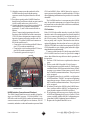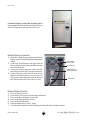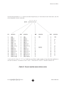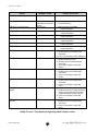
1
Automated Weather Observing System AWOS 2090 CDP User’s Manual 1165 National Drive • Sacramento, CA 95834 • 800.824.5873 • www.allweatherinc.com CONTENTS Contents Introduction ............................................................................................................. 1 AWOS Basics ............................................................................................................. 2 System Components ................................................................................................ 2 I Sensor Station ....................................................................................................2 II Data Collection Platform (DCP) .................................................................... 2 III Central Data Platform (CDP) ......................................................................... 2 IV Remote Display System .................................................................................2 V Uninterruptible Power Source .......................................................................2 Lightning and Transient Surge Protection .......................................................................................................3 AWOS Configurations ...............................................................................................3 AWOS I .................................................................................................................. 3 AWOS II ................................................................................................................. 3 AWOS III ................................................................................................................. 3 AWOS III-P ............................................................................................................. 3 AWOS III-T ..............................................................................................................3 AWOS III-PT ............................................................................................................ 4 AWOS III-PZ ...........................................................................................................4 AWOS III-PTZ .......................................................................................................... 4 AWOS Algorithms ...................................................................................................... 4 Wind Speed and Direction ................................................................................ 4 Wind Gust ............................................................................................................. 4 Variable Wind Direction ..................................................................................... 4 Dew Point ............................................................................................................. 5 Pressure ................................................................................................................5 Ceiling/Sky Condition......................................................................................... 5 Visibility ................................................................................................................. 5 Variable Visibility ................................................................................................. 5 Rainfall Accumulation ........................................................................................5 Present Weather (optional) .............................................................................. 5 Freezing Rain Detection .................................................................................6 Thunderstorm Detection, Model 6500 ............................................................. 6 Thunderstorm Detection, NADIN Interface ....................................................6 Averaging Table ...................................................................................................... 7 Installation ............................................................................................................... 8 Installing the System Unit PC .................................................................................... 8 Installing the Model 20909 Peripheral Interface ..................................................9 Peripheral Interface Connections ................................................................... 9 NADIN Interface (optional) ............................................................................... 9 CLH NADIN Interface Board Installation ....................................................... 9 NADIN Interface Connection and Checkout ........................................... 10 CLH Interface ................................................................................................. 10 ARINC Interface ............................................................................................. 11 AW O S AUTOMATED WEATHER OBSERVING SYSTEM iii User’s Manual CONTENTS UPS Installation ........................................................................................................ 11 Models 20913-D/F ............................................................................................. 11 KVM Extender Installation ...................................................................................... 11 CDP Checkout ........................................................................................................ 13 Remote Display Installation ................................................................................... 14 Remote Display Connections ......................................................................... 16 Remote Display Checkout .............................................................................. 16 AWOS/ATIS Interface .............................................................................................. 17 Installation .......................................................................................................... 19 ATIS Peripheral Interface cable ................................................................... 19 AWOS/ATIS Remote Switch Assembly.......................................................... 19 AWOS/ATIS Interface Assembly ................................................................... 19 Checkout ........................................................................................................... 20 Assembly ................................................................................................................ 21 Model 20901 System Unit Assembly and Configuration .................................... 21 Software Installation ......................................................................................... 21 Peripheral Interface Assembly ............................................................................. 22 CDP Checkout ........................................................................................................ 24 Replacing a 20905-A Internal Modem with the 20905-A External Modem Kit 25 Main Display .......................................................................................................... 26 System Information ................................................................................................. 27 Sensor Displays ........................................................................................................ 27 System Status Information ...................................................................................... 29 Control Menu .......................................................................................................... 29 Getting Help ............................................................................................................ 29 User’s Menus........................................................................................................... 30 Logging In and Out ................................................................................................ 31 Control Menu .......................................................................................................... 31 Operator Menu ...................................................................................................... 32 Weather Remark Control Menu ........................................................................... 32 Voice Control Menu ............................................................................................... 33 Voice Remarks .................................................................................................. 33 Entering Voice Remarks ................................................................................ 33 Recording, accepting, and cancelling voice remarks ........................... 33 Revalidating Voice Remarks ........................................................................ 34 Cancelling Voice Remarks ........................................................................... 34 Voice Output Control Menu ........................................................................... 34 Normal and Inoperative Modes .................................................................. 34 Automatic and Manual Modes ................................................................... 34 Test Mode........................................................................................................ 34 Setting Radio and Telephone Output ......................................................... 35 Printer Control Menu .............................................................................................. 35 Line Printer Output Format .................................................................................... 35 User’s Manual iv AW O S AUTOMATED WEATHER OBSERVING SYSTEM CONTENTS Maintenance Menu .............................................................................................. 36 Diagnostic Display On-Off ..................................................................................... 36 Set Date and Time ............................................................................................ 36 Set Local Time Offset........................................................................................ 44 Voice Status Display ......................................................................................... 44 Display System Parameters ............................................................................. 44 Turning Sensors On and Off ............................................................................. 44 Maintenance Menu Two ....................................................................................... 45 Display Serial Info .............................................................................................. 45 Display DCP Info ................................................................................................ 45 Display Memory Status ..................................................................................... 45 Printer Test .......................................................................................................... 46 Diagnostic Report ............................................................................................. 46 Color Setup Menu ............................................................................................ 46 Archive Menu ........................................................................................................ 47 Display Archive Disk Space ................................................................................... 47 Set Archive Interval ................................................................................................ 47 Archive Data Retrieval .......................................................................................... 48 Retrieving Locked Data ................................................................................... 48 Locking Archive Data ............................................................................................ 48 AWOS Output Modes ............................................................................................. 49 Mode 1—Full-Time Automated Operation ......................................................... 49 Mode 2—Full-Time Automated Operation with Local Notice to Airmen (NOTAM) .................................................................................................................. 49 Mode 3—Full-Time Automated Operation with Manual Weather Augmentation and Local NOTAM Option ............................................................................. 49 Mode 4—Part-Time Manual Operation ............................................................... 50 CDP Maintenance ................................................................................................. 51 Monthly Maintenance ........................................................................................... 51 Quarterly Maintenance......................................................................................... 51 Annual Maintenance ............................................................................................. 51 Warranty ................................................................................................................. 52 Remote Maintenance Monitoring ....................................................................... 53 Overview .................................................................................................................. 53 Hardware Requirements ....................................................................................... 53 Establishing Communication with the AWOS ...................................................... 53 AWOS RMM Commands ........................................................................................ 54 Entering Filenames ................................................................................................. 54 Retrieving Data Files ............................................................................................... 55 Specifying Sensor Names for Online/Offline Processing .................................. 55 Password Processing .............................................................................................. 55 RMM Command Processing and Command Responses ................................. 55 Responses to commands ................................................................................ 55 Terminating the RMM Session ................................................................................ 56 System Drawings ................................................................................................... 57 AW O S AUTOMATED WEATHER OBSERVING SYSTEM v User’s Manual Introduction A The output signals of the AWOS sensors are collected and processed, then displayed on the Central Data Platform’s (CDP) display. The CDP is equipped with All Weather Inc.’s user-friendly graphic interface, which consists of a hierarchical system of interactive menus, providing the user direct control over each station’s operation. The CDP also functions as an independent data logger, storing an ongoing record of weather data and system status. Kept as a permanent record of system operation, this archive data can be viewed or printed at any time using the system’s straightforward Archive Menu functions. A series of remote displays show the current readings computed by the CDP, and can be located up to one mile away from the main stations. ll Weather Inc’s Automated Weather Observing System (AWOS) is a multifaceted, modular weather monitoring system that provides weather data indispensable to recognizing and monitoring airport weather patterns. The AWOS continuously measures an array of weather parameters and can output them to multiple display terminals for interpretation by airport personnel. The sensor configuration of an AWOS is adaptable to the needs of the airport at which it is installed. A comprehensive selection of sensors is available, including: • Wind Speed and Gust • Wind Direction and Variable Wind Direction • Temperature • Dew Point Temperature • Relative Humidity • Barometric Pressure • Precipitation • Visibility and Variable Visibility • Sky Condition • Altimeter Setting • Density Altitude • Present Weather • Lightning and Thunderstorm Detection • Freezing Rain AW O S AUTOMATED WEATHER OBSERVING SYSTEM 1 User’s Manual AWOS Basics System Components Several key functions are initiated at the CDP, including: The AWOS consists of five major components: • Sensor Station • Data Collection Platform (DCP) • Central Data Platform (CDP) • Remote Display System (RDS) • Uninterruptible Power Source (UPS) • • • • Up to two 90-second voice remarks can be entered by the operator at the CDP, and these will then be appended to the ongoing voice report. The voice remark is sometimes used in place of an Automatic Terminal Information System, or ATIS. Weather remarks are entered at the CDP for transmission to the remote displays. This remark will be displayed on the top line of the Weather Remark display box. A running record of measured weather conditions and overall system operation is maintained in the CDP’s archive files for one year. An archive file is an automatic report written to nonvolatile memory once every five minutes. These files may be accessed at any time for viewing or printing using the Archive Menu, available to authorized users through the CDP’s Control Menu. I Sensor Station The AWOS sensor station is located near the touchdown zone of the airport runway. The sensor station includes a combination of the following sensors, depending on the AWOS model: wind speed and direction, temperature, dew point, rainfall, dual barometric pressure sensors, cloud height, visibility, present weather, lightning detection, and freezing rain. II Data Collection Platform (DCP) Located on the sensor tower, the Data Collection Platform (DCP) collects data from the sensors, performs error detection on the received information, converts the sensors’ data into engineering units, and transmits message packets containing sensor data and status information to the Central Data Platform (CDP) once every five seconds. The data packets contain a cyclic redundancy check (CRC) character that allows the CDP to determine if any transmission errors have occurred. The CDP ignores data that is not received correctly. A keypad and display are built into the DCP for sensor maintenance and visibility sensor configuration (8364 series and above). IV Remote Display System The Remote Display System (RDS) consists of a series of remote display units connected to the CDP. Each remote display station includes a central processor and a display. These remote displays present data in the same format as the CDP, and are controlled by the CDP. They are display stations only, with no available menus or configuration controls. III Central Data Platform (CDP) V Uninterruptible Power Source Meteorological data is transmitted by the Data Collection Platform to the Central Data Platform (CDP), which consists of a central processor, a high resolution display, a hard disk drive, floppy disk drive, a keyboard, and a mouse. The CDP receives data from the DCP and outputs current weather data to the Remote Display System (RDS). User’s Manual Set Date and Time Sensors On/Off Enter Voice Remark Enter Weather Remark The sensor station, CDP (including peripheral devices), and remote displays may all be protected by an uninterruptible power source (UPS), which supplies emergency power in the event of a power outage. Two UPS models are available: one will power the system components for a minimum of ten minutes, and the other will provide power for up to one hour. The systems sensors can be powered by optional backup batteries. 2 AW O S AUTOMATED WEATHER OBSERVING SYSTEM AWOS BASICS Lightning and Transient Surge Protection • Rainfall • Day/Night Detection AWOS III The AWOS is protected by a comprehensive network AWOS III systems add a ceilometer to the AWOS II of lightning and transient surge protection components. array. The system provides data for the following paramTranzorbs, MOVs, and resistors protect all sensor lines, eters: power lines, telephone lines, and communication lines • Wind Speed and Gust against lightning-induced surges and power line transients • Wind Direction and and surges. Variable Wind Direction • Temperature • Relative Humidity AWOS Configurations • Dew Point AWOS systems are available in several configurations. • Barometric Pressure The configurations differ primarily in the sensors included • Altimeter Setting and the output method used (landline or radio). The Sys• DensityAltitude tem Drawings chapter of this manual provides block • Visibility and Variable Visibility diagrams of the main configurations: AWOS I, AWOS • Rainfall II, AWOS III, AWOS III-P, AWOS III-T, AWOS III• Day/Night Detection • Cloud Type and Height, up to 3 layers PT, AWOS III-PZ, and AWOS III-PTZ. AWOS III-P AWOS I AWOS I systems provide data for the following param- AWOS III-P systems add a present weather sensor to the AWOS III array. The system provides data for the eters: following parameters: • Wind Speed and Gust • Wind Direction and • Wind Speed and Gust Variable Wind Direction • Wind Direction and • Temperature Variable Wind Direction • Relative Humidity • Temperature • Dew Point • Relative Humidity • Barometric Pressure • Dew Point • Altimeter Setting • Barometric Pressure • DensityAltitude • Altimeter Setting • DensityAltitude AWOS II • Visibility and Variable Visibility AWOS II systems add a visibility sensor, rain gauge and • Rainfall day/night detector to the AWOS I array. The system pro• Day/Night Detection • Cloud Type and Height, up to 3 layers vides data for the following parameters: • Present Weather (rain, snow, drizzle, mist, fog, • Wind Speed and Gust freezing fog, haze) • Wind Direction and Variable Wind Direction AWOS III-T • Temperature AWOS III-T systems add thunderstorm detection to the • Relative Humidity AWOS III array. The system provides data for the fol• Dew Point lowing parameters: • Barometric Pressure • Altimeter Setting • Wind Speed and Gust • DensityAltitude • Wind Direction and • Visibility and Variable Visibility Variable Wind Direction AW O S AUTOMATED WEATHER OBSERVING SYSTEM 3 User’s Manual AWOS BASICS • • • • • • • • • • • • • • • Rainfall Day/Night Detection Cloud Type and Height, up to 3 layers Present Weather (rain, snow, drizzle, mist, fog, freezing fog, haze) • Freezing Rain Temperature Relative Humidity Dew Point Barometric Pressure Altimeter Setting DensityAltitude Visibility and Variable Visibility Rainfall Day/Night Detection Cloud Type and Height, up to 3 layers Thunderstorm/Lightning Detection AWOS III-PTZ AWOS III-PTZ systems add a freezing rain sensor to the AWOS III-PT array. The system provides data for the following parameters: • Wind Speed and Gust AWOS III-PT • Wind Direction and AWOS III-PT systems add thunderstorm detection to Variable Wind Direction the AWOS III-P array. The system provides data for the • Temperature following parameters: • Relative Humidity • Dew Point • Wind Speed and Gust • Barometric Pressure • Wind Direction and • Altimeter Setting Variable Wind Direction • DensityAltitude • Temperature • Visibility and Variable Visibility • Relative Humidity • Rainfall • Dew Point • Day/Night Detection • Barometric Pressure • Cloud Type and Height, up to 3 layers • Altimeter Setting • Present Weather (rain, snow, drizzle, mist, fog, • DensityAltitude freezing fog, haze) • Visibility and Variable Visibility • Thunderstorm/Lightning Detection • Rainfall • Freezing Rain • Day/Night Detection • Cloud Type and Height, up to 3 layers • Present Weather (rain, snow, drizzle, mist, fog, AWOS Algorithms freezing fog, haze) • Thunderstorm/Lightning Detection Wind Speed and Direction AWOS III-PZ Wind speed and wind direction are two-minute running averages calculated from sensor readings taken at onesecond intervals. When speed is less than or equal to two knots, the system indicates calm wind conditions. AWOS III-PZ systems add a freezing rain sensor to the AWOS III-P array. The system provides data for the following parameters: • Wind Speed and Gust • Wind Direction and Variable Wind Direction • Temperature • Relative Humidity • Dew Point • Barometric Pressure • Altimeter Setting • DensityAltitude • Visibility and Variable Visibility User’s Manual Wind Gust Wind gust is based upon the highest wind speed for the past 10 minutes. Variable Wind Direction Variable wind direction is a wind direction that varies around the two-minute average wind direction by 60 degrees or more. 4 AW O S AUTOMATED WEATHER OBSERVING SYSTEM AWOS BASICS Ambient Temperature Ceiling/Sky Condition Ambient temperature is a five-minute average temperature calculated each minute from sensor readings taken at one-second intervals. Temperature will not be reported if the 8190 MARS fan fails. Ceiling and sky condition are determined from sensor outputs at least every 30 seconds integrated over a 30minute sample period. A weighting scheme is employed for data collected during the last 10 minutes of the 30minute sample period to make the algorithm more reDew Point sponsive to rapid changes in ceiling/sky conditions. Heights Dew point temperature is a five-minute average dew point are reported in hundreds of feet (for example, 30 repretemperature calculated each minute from sensor read- sents a height of 3000 feet). ings taken at one-second intervals. If less than four valid one-minute values are available, dew point is reported as Visibility missing. Dew point temperature will not be reported if Visibility is a ten-minute average calculated each minute the 8190 MARS fan fails. from sensor readings taken at ten-second intervals. The visibility sensor also performs self-checks of communiPressure cations, window condition, and a number of operational For quality control purposes, the AWOS includes at least functions, and reports any errors in its status word(s). two pressure sensors. The definitions below apply to Variable Visibility AWOS installations. Variable visibility is based on visibility readings, and is Altimeter Setting only reported if visibility is -3 miles, and the difference The pressure value to which the altimeter of an aircraft on between the maximum and minimum visibility values meathe ground is set so that it will indicate the field elevation sured in the last ten minutes is greater than one-half mile. (mean sea level) of the airport. The two pressure sensors must agree to within .04 inHg for altimeter setting to be Rainfall Accumulation reported. Also, the temperature read inside the 7190 Rainfall accumulation shows the amount of rainfall (in 0.01” sensor must be >-40°C and <60°C. increments) measured during the past hour. This value is updated every five seconds, and is reset to zero at five Field Elevation (Ha) The officially designated field elevation of an airport above seconds past the hour. mean sea level. It is the elevation of the highest point on Present Weather (optional) any of the airport’s runways. Present weather data is averaged over a one-minute period by the present weather sensor and is updated every Density Altitude (DA) The altitude in the standard atmosphere where air densi- one minute. The type of precipitation detected (Rain, ty is equivalent to that of the airport. This is used by pilots Drizzle, Snow) is reported as explained in the Sensor to determine aircraft performance. Density altitude is not Displays section of this manual. Rainfall rate is deterreported if it is less than 1000’ above the field elevation. mined from the type and concentration of the detected precipitation, and is updated every one minute. Sensor Pressure (P) If a present weather sensor and a visibility sensor are The atmospheric pressure at the actual elevation of the installed and reporting properly, the following will be resensor (Hz). ported when the present weather sensor is reporting “NO PRECIPITATION”: Station Elevation (Hp) The officially designated height above mean sea level to HAZE Visibility <7 sm and dew point depression >4°F which station pressure (Ps) pertains. Hp is the same as MIST Visibility >1/2 sm and <7 sm, and for Ha for AWOS airport installations. dew point depression ≤4°F AW O S AUTOMATED WEATHER OBSERVING SYSTEM 5 User’s Manual AWOS BASICS FOG FREEZING FOG Visibility ≤1/2 sm, dew point depression ≤4°F, and temperature >32°F Thunderstorm Detection, Model 6500 Thunderstorm/lightning data is reported for any lightning activity detected within a 30 nm radius of the installation site as explained in the Sensor Displays section of this manual. The data is divided into three distance ranges: <5 nm, 5-10 nm, and >10-30 nm. Activity detected in the >10-30 nm range also includes direction information, reported in octants (Northwest, Southeast, etc.). Lightning data is updated every 5 seconds, and uses a 15minute sliding window (reported lightning activity includes all strikes detected within the past 15 minutes). The system displays may take up to one minute to reflect the new input. Visibility ≤1/2 sm, dew point depression ≤4°F, and temperature ≤32°F (Note: In order for the Present Weather sensor’s rainfall rate value to be displayed, the Rain Gauge option must be turned ON through the Sensors ON/ OFF menu (found on Maintenance Menu One). This option must be ON whether or not a separate rain gauge is installed.) Freezing Rain Detection With the addition of a Model 6495 Freezing Rain Sensor, the AWOS Present Weather field can incorporate Thunderstorm Detection, NADIN Interface freezing rain detection. The Freezing Rain Sensor is polled Using the optional NADIN interface link, thunderstorm/ once per minute. lightning data is updated every one minute. The system displays may take up to one minute to reflect the new input. User’s Manual 6 AW O S AUTOMATED WEATHER OBSERVING SYSTEM AWOS BASICS Averaging Table (Table 1) Sensor averaging. Sensor Reporting Units Averaging Times Time to First Report after CDP Power Up Wind Speed Knots 2 minutes 90 seconds Wind Gust (last 10 minutes) Knots 5 seconds 90 seconds Wind Direction Nearest 10 degrees magnetic 2 minutes 90 seconds Variable Wind Direction Nearest 10 degrees magnetic 5 seconds 90 seconds Temperature Celsius 5 minutes 3 minutes Dew Point Celsius 5 minute 3 minutes Altimeter Setting Inches of mercury 5 seconds 1 minute Density Altitude Feet 5 seconds 3 minutes (not reported if <1000' above field elevation) Visibility Statute miles 10 minutes 8 minutes Variable Visibility Statute miles 1 minute 8 minutes Precipitation 0.01 inches 5 second update < 1 minute Sky Condition (Up to 3 Cloud Layers) 100 feet 30 minutes 24 minutes Clear (CLR) no clouds below 12,500 feet Few ≥6% to 24% sky cover Scattered (SCT) ≥25% to 49% sky cover Broken (BKN) ≥50% to 87% sky cover Overcast (OVC) >87% sky cover Obscured (VV) Cloud bases at surface/fog Thunderstorm Thunderstorm/Lightning and Direction 15-minute sliding window 1 minute Present Weather precipitation type and rate 1 minute 1 minute Freezing Rain freezing rain 1 minute 1 minute AW O S AUTOMATED WEATHER OBSERVING SYSTEM 7 User’s Manual Installation 1 Install the System Unit PC in a location where convenient access to power and to the necessary communication links is available. 2 The monitor can be installed on its included desktop stand, or mounted to a wall using the M488297-00 wall mount kit. Follow the instructions included with the kit to install the wall bracket and monitor. A 35’ monitor extension cable is included in the kit for installations where the monitor is located away from the CDP. 3 Connect the Monitor to the monitor port on the back of the System Unit PC. 4 Connect the keyboard and mouse to the two input connectors on the provided Y-cable, then connect the Y-cable to the DIN port on the back of the System Unit PC. 5 Connect the printer (if used) to the parallel port on the back of the System Unit PC. 6 Connect the microphone to the MIC IN connector on the sound card. 7 Set the Voltage Selector Switches to the proper settings, if not auto-switching. 8 Connect the System Unit PC power cord to a compatible power source. Two speakers connect to the System Unit. One speaker is the main speaker, to which all speaker cables connect. This speaker also powers the second (left) speaker. 9 Connect the speaker power cord to the main speaker. 10 The speaker INPUT cable connects to the speakers from J8 on the Peripheral Interface PCB after installation of the Peripheral Interface in the next section. 11 Connect the interface cable to the 1791 radio (if used) as explained in the Model 1791 User’s Manual. 12 Set up the printer according to the printer manual (ribbon, paper, etc.) and connect to the System Unit’s printer port. 13 Power on the System Unit and set the system clock to the current GMT. The CDP installs indoors, and consists of: • System Unit PC (Model 20901) • Voice/RMM Modem (Model 20905-A) • Sound Card (Model 20903) • Monitor (M482179-00) • Keyboard (M406059) • Mouse (M406060) • Printer (Model 20910-A/B) • Microphone (20906) • Speakers (Model 20904) • Peripheral Interface (Model 20909) • UHF Radio (Model 20980-A—optional) • NADIN Interface (Model M404806— optional) • Landline to DCP (if no UHF radio) • VHF Radio (Model 1791) • Telephone Line (customer supplied) • Optional Uninterruptible Power Source (Model 20913-D/F) • Optional KVM extender kit (Model M488300-00) All the CDP equipment will fit on a desktop that is at least 30" x 60". It must be located in a conditioned space where the temperature is maintained between 40° and 105° F, and between 5% and 90% relative humidity, and within three feet of an outlet with 120VAC or 220VAC, 50 or 60Hz. The CDP requires 500VA and should be on a dedicated 15Amp circuit. It must be located within three feet of a telephone line terminated with an RJ-11 connector. The phone line is dedicated to the AWOS and must not be shared with other telephones, FAX machines, or other equipment. Installing the System Unit PC The System Unit PC (20901) performs data processing on incoming AWOS data and controls I/O communications with the Peripheral Interface, NADIN Interface, DCP, and peripherals. If the optional KVM extender kit is used, follow the installation instructions in the section for the optional KVM Extender kit. User’s Manual 8 AW O S AUTOMATED WEATHER OBSERVING SYSTEM INSTALLATION Installing the Model 20909 Peripheral Interface 4 5 The Peripheral Interface (20909) is housed within a separate enclosure with the UHF/VHF Data Link Radio (if used) and optional NADIN interface. The Peripheral Interface provides the circuitry and connections necessary for supporting a NADIN interface, UHF Radio, VHF radio, DCP landline connection, speakers, and telephone connection. It includes RS-232 to RS-485 modems with surge suppression, telephone line surge suppression, and audio filtering circuits. The Peripheral Interface installs near the System Unit, and communicates with it via several cable assemblies. These cables are first connected to the Peripheral Interface’s PCB, as explained below, and then to the System Unit. 6 7 NADIN Interface (optional) CLH NADIN Interface Board Installation The optional NADIN interface board (M404806) used with the CLH NADIN system allows AWOS data to be submitted to the Weather Message Switching Center (WMSC) for dissemination to flight center stations, DUAT, etc. It can also be used to add thunderstorm and lightning detection capabilities to the AWOS. The NADIN interface connects to a plug-in connector on the Peripheral Interface board, with the incoming RS232 line from the Pan-Am satellite connecting to a terminal block on the upper side of the NADIN Interface. 1 Mount the included standoffs between the NADIN interface board and Peripheral Interface PCB as shown in drawing 20909-003. Peripheral Interface Connections 1 2 3 Bundle the cables on the inside of the Peripheral Interface chassis with the provided cable clamps and hardware. Use cable ties every 12” to secure the cables on the outside of the Peripheral Interface. Install flex guard tubing between the System Unit and Peripheral Interface. Set the Peripheral Interface line voltage selector switch for the proper voltage, and connect the power cable to the power input connector on the rear panel. Connect the serial cable from the System Unit (M491552) to the DB9 COM 1 connector on the rear panel. Remove the cover from the Peripheral Interface to expose the Peripheral Interface PCB. Route the external cables from the System Unit, telephone line, RS-485 landline (if used), remote displays (if used), and VHF radio through the hole in the case’s rear panel and connect to the Peripheral Interface PCB as shown in the Peripheral Interface Connections table below. Install the NADIN interface cable, if used (see next section). Peripheral Interface Connections Source Cable Part Number System Unit Connector Peripheral Interface Connector Voice/RMM modem card (System Unit) part of 20905-A MODEM DB25 MODEM Sound card (System Unit) M491553 SPK OUT J7 (VOICE IN) Telephone line n/a n/a J1 (PHONE IN) RS-485 landline (if used) n/a n/a RS-485 converter D+, D-, and gnd Remote displays (if used) n/a n/a RS-485 converter D+, D-, and gnd VHF radio M491686 n/a J2: pin 1--WHITE; pin 2--GREEN; pin 3--RED; pin 4--BLACK Speakers (INPUT) part of 20904 n/a J8 (SPK OUT) Data link radio antenna M491361 n/a ANT on data link radio AW O S AUTOMATED WEATHER OBSERVING SYSTEM 9 User’s Manual INSTALLATION 2 Align the connector on the underside of the NADIN interface board with the mating connector on the Peripheral Interface board (J14). 3 Press down gently on the NADIN Interface board (being careful not to bend any pins) until it is fully seated, and secure with 4 screws. 4 Connect the three wires of the incoming RS232 cable from the CLH satellite connection to terminals 1, 2, and 3 of the terminal block as follows: (Note: Connection designations refer to the function of the NADIN end of the connection (TX, RX); these designations connect to their opposite counterparts on the satellite end. For example, TX on the NADIN end connects to RX on the satellite end.) • Connect the wire from the satellite RX line to pin 1 (TX) on the terminal block. • Connect the wire from the satellite TX line to pin 2 (RX) on the terminal block. • Connect the ground wire to pin 3. CLH and ARINC allow AWOS data to be sent to remote systems via telephone or satellite uplinks. CLH also allows lightning information to be processed via a satellite downlink. The NADIN interface is transparent to the AWOS user. No periodic maintenance is required. Once the initial connection as described below has been established, no further action is required. CLH Interface If the CLH Z-Link satellite interface is used, the 20909 interface unit will contain an interface board (installed above) to connect to the RS232 serial data interface of the Z-Link system. This interface is 1200 baud, 8 data bits, no parity, and 1 stop bit. This interface also allows optional lightning detection data to be received by the AWOS CDP if this service has been requested. The 2090 CDP is then able to voice, display, print, and archive lightning/thunderstorm information. Connect a cable from the Z-Link System to the 20909 CLH NADIN interface board as specified in step 4 standoffs above, then follow the steps below to check operation of the interface. 1 Perform CDP checkout as explained on the next page. 2 Power on the AWOS and the Z-Link Systems. 3 Using diagnostics available on the Z-Link System, confirm that the AWOS transmits the binary ADAS message every minute. If data is not received, check the Tx and Rx communication lines. They may need to be swapped. 4 If a lightning interface is available, verify that the AWOS transmits “TMOK” in response to lightning input data messages. If data is not received, check the Tx and Rx communication lines. They may need to be swapped. 5 If no data is sent by the AWOS to the NADIN interCLH NADIN terminal block face, confirm with the AWOS Configuration prointerface board gram, that the output to NADIN is enabled. NADIN Interface Connection and Checkout 6 If no lightning data messages are displayed by the AWOS and lightning data is active on the Z-Link The 2090 Central Data Processor is capable of interfacsystem, confirm with the AWOS Configuration proing to two NADIN systems: CLH and ARINC. NAgram that NADIN Lightning Input is enabled. DIN allows the local AWOS weather information to be sent to remote users at Flight Service Stations, DUAT 7 Replace the Peripheral Interface cover. terminals, and other weather information systems. Both User’s Manual 10 AW O S AUTOMATED WEATHER OBSERVING SYSTEM INSTALLATION ARINC Interface units, a transmitter (located at the CDP computer) and If the ARINC NADIN interface is used, follow the steps the receiver (located at the desired use location). below to connect the interface and check its operation. 1 Perform CDP checkout as explained below. 2 Connect a data cable with a DB-9 connector to the 20901’s Serial 2 port. 3 Connect the other end of the data cable to the ARINC equipment. 4 The AWOS will output a METAR formatted text message, ASCII, 9600 baud, 8 data bits, no parity, 1 stop, every five minutes. Verify using ARINC diagnostics that the data is being received from the AWOS. If data is not received, check the Rx and Tx data communication lines. They may have to be swapped. If no communication is observed, check the 20901 BIOS settings for UART2 and verify that it is set according to the setup parameters in this manual. The interface inside the 20909 chassis is not required for ARINC NADIN interfaces. All Weather Inc. also recommends that an RS232 surge suppressor be installed in-line with the RS232 data. This will help prevent damage to the AWOS CDP in the event of a surge on the RS232 data lines. Each of the two units have their own power supply and are connected to each other through a standard CAT5 (or better) patch cord up to 500 feet apart. Both units can have a keyboard, mouse, monitor, and microphone connected. Each set can access the CDP and both monitors will show the same display. The DIP switch on the back and the selector switch on the front of the transmitter module should be left in their default position. Refer to the manual provided with the KVM extender modules for more information on the switch settings. 1 Install the System Unit PC in a location where convenient access to power and to the necessary communication links is available. 2 Connect the DB25 end of the cable provided with the transmitter module of the KVM to the input connector on the back of the transmitter module. 3 The CDP monitor can be installed on its included desktop stand, or mounted to a wall using the M488297-00 wall mount kit. Follow the instructions included with the kit to install the UPS Installation Models 20913-D/F If a Model 20913-D or F uninterruptible power source (UPS) is used at the CDP, install it and connect the CDP components as follows: 1 Connect a six-outlet power strip to an outlet on the UPS. 2 Connect the System Unit, Peripheral Interface, and monitor to the UPS. 3 Connect the 1791 VHF radio, speaker power supply, and printer to the outlet strip. 4 Connect the UPS to a properly grounded AC outlet. 5 Power on the outlet strip. 6 Power on the UPS. KVM Extender Installation The KVM Extender kit (M488300-00) contains the KVM extender module and all of the components required to have a second, or remote station attached to the CDP. The KVM extender module consists of two AW O S AUTOMATED WEATHER OBSERVING SYSTEM 11 User’s Manual INSTALLATION wall bracket and monitor. A 35’ monitor extension cable is included in the kit for installations where the monitor is located away from the CDP. 4 Connect the Monitor to the monitor connector on the back of the transmitter unit. Connect the monitor connector on the DB25 cable to the monitor port on the back of the System Unit PC. 5 Connect the keyboard and mouse connectors on the DB25 cable to the two input connectors on the provided Y-cable, then connect the Ycable to the DIN port on the back of the System Unit PC. Connect the CDP mouse to the mouse port on the front of the transmitter module. Connect the CDP keyboard to the keyboard port on the front of the transmitter module. 6 Connect the printer (if used) to the parallel port on the back of the System Unit PC. 7 Connect the CDP microphone to the microphone connector on the front of the transmitter module. Connect one of the 3.5mm stereo cables provided with the transmitter module to the MIC IN connector on the sound card and the microphone connector on the back of the transmitter module. 8 Set the Voltage Selector Switches to the proper settings, if not auto-switching. 9 Connect the System Unit PC power cord to a compatible power source. Two speakers connect to the System Unit. One speaker is the main speaker, to which all speaker cables connect. This speaker also powers the second (left) speaker. 10 Connect the speaker power cord to the main speaker. 11 The speaker INPUT cable connects to the speaker jack on the front of the transmitter module. Connect the other 3.5mm stereo cable provided with the transmitter module to the speaker jack on the back of the transmitter module and J8 on the Peripheral Interface PCB after installation of the Peripheral Interface in the next section. 12 Connect the interface cable to the 1791 radio (if used) as explained in the Model 1791 User’s Manual. User’s Manual 13 Set up the printer according to the printer manual (ribbon, paper, etc.) and connect to the System Unit’s printer port. 14 Power on the System Unit and set the system clock to the current GMT. 15 Connect a CAT5 (or better) patch cord to the back of the transmitter module at the REMOTE I/O RJ-45 jack. 16 Connect the power supply provided with the transmitter module (the power supply for the transmitter and receiver modules are the same) to the power jack on the back of the transmitter module. Plug the power supply into AC power. 17 The remainder of the KVM extender kit is installed at the desired use location for the remote station. When routing the patch cord from the transmitter module to the location for the remote module, ensure that the patch cord is protected from damage and is not readily accessible. Plug the patch cord into the REMOTE I/O RJ-45 jack on the back of the receiver module. 18 The extender kit monitor can be installed on its included desktop stand, or mounted to a wall using the M488297-00 wall mount kit. Follow the instructions included with the kit to install the wall bracket and monitor. A 35’ monitor extension cable is included in the kit for installations where the monitor is wall mounted. 19 Connect the monitor cable to the monitor connector on the back of the receiver module. 20 Connect the 3.5mm stereo cable provided with the monitor to the speaker jack on the monitor and the speaker jack on the front of the receiver module. The volume of the speakers built in to the monitor can be adjusted using the monitor’s controls. 21 Connect the keyboard to the keyboard connector on the front of the receiver module. Connect the mouse to the mouse connector on the front of the receiver module. 22 Connect the microphone to the microphone connector on the front of the receiver module. 23 Connect the power supply provided with the receiver module (the power supply for the transmitter and receiver modules are the same) to the power jack on the back of the receiver module. Plug the power supply into AC power. 12 AW O S AUTOMATED WEATHER OBSERVING SYSTEM INSTALLATION CDP Checkout 1 2 3 4 5 6 7 8 Power on the UPS, if used. Power on the CDP system (System Unit, monitor, printer, speakers). Power on the Peripheral Interface. Power on the VHF radio. Verify that the system boots and that the AWOS program starts. Verify printer, display, keyboard, mouse, speaker, VHF radio, and telephone modem operation. Replace the cover on the Peripheral Interface. If the KVM Extender kit is installed, verify the operation of the remote display, keyboard, mouse, microphone, and speakers. AW O S AUTOMATED WEATHER OBSERVING SYSTEM 13 User’s Manual INSTALLATION Remote Display Installation This section describes how to install a new Model 2091 Remote Display for use in a 900 Series AWOS. Use caution in performing all of the following steps to prevent damage to the equipment due to electrostatic discharge. Work should only be performed by qualified service personnel in a suitable environment. All the Remote Display equipment will fit on a desktop that is at least 30" x 60". The Remote Display must be located in a conditioned space where the temperature is maintained between 40° and 105° F, and between 5% and 90% relative humidity, and within three feet of an outlet with 120VAC or 220VAC, 50 or 60Hz. The Remote Display requires 200VA, and should be on a dedicated 15Amp circuit. Monitor Remote Display System Unit UPS cover screws ac line voltage selector switch AC power cord 1) Remote Display System Unit, rear view, showing a typical final configuration. To remove the cover, remove the six Phillips head screws shown. RS485 cable from Peripheral Interface monitor cable cover screws User’s Manual 14 AW O S AUTOMATED WEATHER OBSERVING SYSTEM INSTALLATION 2) Remote Display System Unit cover removal. After removing the screws from the rear panel, slide the Remote Display System Unit’s cover back several inches, then lift the cover up and off. RS485 cable from Peripheral Interface 3) Remote Display System Unit rear panel. Route the Peripheral Interface data cable and Wind Reporter data cable in through the Remote Display System Unit’s back panel. 4) Remote Display internal PCB (M404813). Connect the incoming RS-485 cable from the Peripheral Interface to J2, pins 5 (-) and 6 (+). Connect the Wind Reporter’s data cable to J2, pins 7 (-) and 8 (+). (Note: Consult All Weather Inc. for RS-485 cable specifications. Special cable may be required for runs longer than 100’.) 5) Removing the floppy drive cover from the Remote Display. System Unit When installing software, it is first necessary to expose the floppy disk drive. To do this, gently pry the cover from the floppy drive bay with a small screwdriver as shown. AW O S AUTOMATED WEATHER OBSERVING SYSTEM 15 User’s Manual INSTALLATION 6) Remote Display System Unit with floppy drive cover removed. Insert the Remote Display software disk in the floppy drive and replace the drive cover. Remote Display Connections 1 2 3 4 Set the line voltage selector switches on the Remote Display System Unit and Wind Reporter to the proper settings. Connect the Wind Reporter data cable from the Remote Display System Unit to the DB9 connector on the Wind Reporter. Connect the monitor and power cables to the Remote Display System Unit’s rear panel connectors. Connect the power cables from the System Unit, Monitor, and Wind Reporter to an AC source. If a UPS is used, connect the power cables to outlets on the UPS and connect the UPS to the AC source. ac line voltage selector switch AC power cord RS485 cable from Peripheral Interface monitor cable Remote Display Checkout 1 2 3 4 5 6 7 Power on the UPS, if used. Power on the CDP System Unit and Peripheral Interface Power on the Remote Display System Unit. Power on the Remote Display monitor. Power on the Wind Reporter. Set the Wind Reporter to “INST” mode. Verify that data is displayed on the Wind Reporter and on the Remote Display monitor. User’s Manual 16 AW O S AUTOMATED WEATHER OBSERVING SYSTEM INSTALLATION AWOS/ATIS Interface This section describes how to install an AWOS/ATIS Interface for use in a 900 Series AWOS. The FCC Title 47 (regulation 87.527c) only allows one VHF frequency for sites that have both ATIS and AWOS systems. The AWOS/ATIS Interface connect the VHF and telephone modem outputs of both of these systems to one VHF transmitter and one telephone modem. A switch controls the mode of the VHF transmitter and modem. Power (+12VDC) is supplied by the CDP Peripheral Interface. 2941 Remote Switch AWOS 900 CDP Peripheral Interface VHF Transmitter VHF Audio VHF Keying Modem Audio VHF Audio VHF Audio 2940 / 2942 Switching Interface VHF Keying VHF Keying Modem Audio Modem Audio Telephone Modem ATIS System There are two different enclosures for the ATIS Interface. The Model 2940 is a 19” rack mountable enclosure. This model fits into the standard ATIS communication rack or any other standard 19” rack. The 2940 is a one rack unit (1RU) enclosure. There is no external mode switch on the 2940, therefore a Remote Switch (Model 2941) is required. Front Back AW O S AUTOMATED WEATHER OBSERVING SYSTEM 17 User’s Manual INSTALLATION The desktop enclosure for the ATIS Interface is Model 2942. This model has a LED and mode switch on the front of the enclosure and does not require the remote switch. However, the remote switch can still be used with this model. The Model 2941 Remote Switch can be up to 1000 feet away from the ATIS Interface and is connected to the interface with a CAT5 (or better) patch cord. The Remote Switch has a switch guard over the switch to prevent the accidental switching to ATIS mode for the ATIS Interface. The switch guard must be lifted before the switch canbe changed to AWOS mode. When the switch guard is closed, the switch is automatically switched to ATIS mode. There is a LED that is lit when the switch is in AWOS mode. The ATIS Peripheral Interface cable (Model M491838-00) is include with both enclosure models (2940 and 2942). This cable provides the CAT5 (or better) patch cord connection to all of the required connections to the inside of the Model 20909 Peripheral Interface assembly. This cable connects to the power supply inside the Peripheral Interface as well as the modem audio and VHF radio outputs. User’s Manual 18 AW O S AUTOMATED WEATHER OBSERVING SYSTEM INSTALLATION Installation provided. It is recommended that this be a black cable or be marked in some way as a black cable to keep the color scheme of the interface assembly. ATIS Peripheral Interface cable The ATIS peripheral interface cable must be installed to allow the AWOS/ATIS Interface assembly to connect to the AWOS 1 Turn off the power switch on the AWOS Peripheral Interface (Model 20909). 2 Remove the side cover on the Peripheral Interface and lay the interface on its side. 3 Disconnect any existing connections at J2 terminals 1 through 4 as well as the J4 Telephone Audio jack. 4 Remove the coupler from the ATIS Peripheral Interface cable (Model M491838-00), as necessary, to feed the cable (RJ-45 connector side) from the inside of the peripheral interface, through the cable access with the other cables exiting the peripheral interface. Reattach the coupler to the RJ-45 connector on the end of the interface cable. 5 Wire the Brown wire pair from the interface cable to terminals 1 and 2 of J2 on the Peripheral Interface PCB. The Brown wire should be on terminal 1 and the WHT/BRN wire on terminal 2. 6 Wire the Green wire pair of the interface cable to terminals 3 and 4 of J2 on the board. The Green wire should be on terminal 3 and the WHT/GRN wire on terminal 4. 7 Plug the 3.5mm stereo jack on the Blue wire pair of the interface cable into J4 on the Peripheral Interface board. 8 Connect the 4-pin Molex connector on the Orange wire pair of the interface cable to one of the unused power cables from the power supply in the Peripheral Interface. AWOS/ATIS Interface Assembly The 2940 Rack Mount Interface assembly is mounted into any 19” equipment rack with the four 10-32 SEMS screws provided with the assembly. The normal location for the installation of this assembly is in the communication rack for the ATIS equipment. This rack has the punch down blocks to connect the ATIS to the VHF radio and the telephone modem. The Model 2942 Interface assembly can be located anywhere between the AWOS and ATIS equipment, however, it is usually located with the AWOS Peripheral Interface (Model 20909). Regardless of which model of ATIS Interface is used, the connections to the interfaces are the same. The back of the interface assembly has four RJ-45 jacks for the connections to the AWOS and ATIS equipment as well as the Remote Switch assembly. Each of these jacks are color coded to aid in the installation of the Interface assembly. Each of these jacks will have a patch cord connected as part of the installation (except for the Black jack if the Remote Switch is not used). Each of these patch cords should be routed to prevent undue stress on the cable and should preferrably be protected with some kind of conduit or cable ducting. 1 The patch cord from the Remote Switch assembly (if used) must be connected to the Black RJ-45 jack on the back of the Interface. 2 The Blue RJ-45 jack receives the cable from the AWOS Peripheral Interface. If the Model 2942 is AWOS/ATIS Remote Switch Assembly used, it is expected that the assembly is close enough The Remote Switch, Model 2941, should be mounted to the Peripheral Interface that the coupler is where the mode of the AWOS/ATIS switch is controlled. removed from the Peripheral Interface cable and The switch assembly can be mounted a vertical or connected directly to the Blue jack on the back of horizontal surface with the provided machine screws. the AWOS/ATIS Interface assembly. If the Model A CAT5 (or better) patch cord must be run between 2940 is used, the supplied Blue patch cord is used to connect the Peripheral Interface cable assembly to the Remote Switch assembly and the AWOS/ATIS the Blue jack on the back of the Interface assembly. Interface assembly. This cable is not part of the kits AW O S AUTOMATED WEATHER OBSERVING SYSTEM 19 User’s Manual INSTALLATION Since the expected wiring of the ATIS to VHF radio 4 Route the Gray patch cord provided between the Interface assembly (silver/chrome jack) and the VHF and telephone modem is through a punch down block, radio and telephone modem audio input. The Green a pair of short solid-wire patch cords and couplers wire pair connects to the PTT keying input of the have been provided. The couplers are just attached VHF radio. The Brown wire pair connects to the to the end of the long patch cord and to one of the audio input of the VHF radio. The Blue wire pair ends of the short patch cord. The other end of the connects to the audio input of the telephone modem. short cord is cut off and the insulation stripped back. Polarity of these wires is not important. These wires can now be used on the punch block to Checkout make the connects to the ATIS. 1 Power on the AWOS with the AWOS/ATIS mode 3 Route the White patch cord provided between the switch in the AWOS position. Verify the red LED is Interface assembly (white jack) and to the outputs lit. provided by the ATIS system. These outputs are the 2 Verify the AWOS audio is heard over the VHF raVHF PTT Keying output, VHF audio output, and dio and adjust modulation as necessary. Telco audio output. The Green wire pair connects 3 Verify the AWOS audio is heard over the telephone to the PTT Keying output of the ATIS. The VHF modem and adjust audio levels as necessary. audio output connects to the Brown wire pair. The 4 Switch the mode switch to ATIS. Telco audio connects to the Blue wire pair. Polarity 5 Verify the ATIS audio is heard over the VHF radio. of these wires is not important. 6 Verify the ATIS audio is heard over the telephone modem. User’s Manual 20 AW O S AUTOMATED WEATHER OBSERVING SYSTEM Assembly 1 Connect the keyboard, monitor, and power cables to the 20901 unit 2 Power on the monitor and CPU 3 Verify operation of the monitor, system unit, and keyboard 4 Re-boot the system unit (press CTRL-ALT-DEL) 5 Power off the CPU 6 Remove the power cable, keyboard cable, and monitor cable from the system unit 7 Remove the cover from the system unit. 8 Install the sound card and serial card. 9 Use a Phillips screw driver to fasten the cards into place with the card panel mounting screws. 10 Set the CPU card jumpers to enable the timer, and set the timeout period to the maximum available. 11 Reinstall the chassis cover and secure the screws. This section explains how to assemble and configure a Model 20901 System Unit, Model 20909 Peripheral Interface, and Model 2091 Remote Display for use in a 900 Series AWOS. These procedures are normally performed at All Weather Inc. prior to system integration, but are included for use during servicing of the system. Use caution in performing all of the following procedures to prevent damage to the equipment due to electrostatic discharge. Work should only be performed by qualified service personnel in a suitable environment. Model 20901 System Unit Assembly and Configuration This section explains how to assemble and configure a Model 20901 System Unit for use in a 900 SeriesAWOS, and how to install new software or hardware in the sys- Software Installation tem unit. This procedure is normally performed at All Install each of the following floppy disks from DOS: Weather Inc. prior to system integration, but is included Mouse driver for use during servicing of the system unit. Sound card drivers Time standard drivers Unpack and identify the following components: AWOS words • 20901 central processor unit (Pentium 133 or AWOS system programs higher, 16 Mb ram or more, 1.2 GB hard disk or greater, 3.5” floppy drive, 4 free ISA slots, 2 For each disk: serial ports, 1 parallel printer port) 1 Insert the disk in drive A:. • M482179-00 monitor 2 Select drive A: by typing “A:”, then hitting Return. • M406060 2-button PS2 mouse 3 Type the command “INSTALL”, then hit Return. • M406059 keyboard with PS2 connector • M406061 mouse pad • 20904 speakers • 20906 microphone • 20903 sound card (Creative Labs Soundblaster Model SB2961) • 20905-A telephone modem AW O S AUTOMATED WEATHER OBSERVING SYSTEM 21 User’s Manual ASSEMBLY Peripheral Interface Assembly The Peripheral Interface (20909) is housed within a separate enclosure with the UHF/VHF Data Link Radio (if used) and optional NADIN interface. The Peripheral Interface provides the circuitry and connections necessary for supporting a NADIN interface, UHF Radio, VHF radio, DCP landline connection, speakers, and telephone connection. It includes RS-232 to RS-485 modems with surge suppression, telephone line surge suppression, and audio filtering circuits. This section describes how to assemble a new Model 20909 Peripheral Interface for use in a 900 Series AWOS. This procedure is normally performed at All Weather Inc. prior to system integration, but is included for use during servicing of the system unit. Use caution in performing all of the following steps to prevent damage to the equipment due to electrostatic discharge. Work should only be performed by qualified service personnel in a suitable environment. 1 2 3 4 align and fasten with screw Remove the cover from the Peripheral Interface. If a data link radio is to be used, mount the radio to the Peripheral Interface PCB (M404810) before installing the PCB in the case. Mount the data link radio to the underside of the Peripheral Interface PCB through the mounting holes shown. Connect the data link radio cable to the radio. User’s Manual 22 align and fasten with screw AW O S AUTOMATED WEATHER OBSERVING SYSTEM ASSEMBLY mounting holes 5 6 Mount the Peripheral Interface PCB (M404810) to the standoffs within the Peripheral Interface case with screws inserted through its corner holes, oriented as shown. Set jumper JP1 for the type of data link used: • Installed for RS-485 landline • Removed for radio data link chassis rear chassis bottom mounting holes 7 Connect the ribbon cable from the case’s external COM port connector to J11 on the Peripheral Interface PCB, and screw down. power 8 power LED HDD LED COM port Connect the internal cables to the Peripheral Interface PCB: • data link radio cable to J12; screw down • power cable to J10 • Power LED to J16 • HDD LED to J17 Note: If the power LED does not come on after power is applied, reverse the PCB connector. If the HDD LED stays on steadily after applying power, reverse its PCB connector. AW O S AUTOMATED WEATHER OBSERVING SYSTEM radio 23 User’s Manual ASSEMBLY Source Cable Part Number System Unit Connector Peripheral Interface Connector Voice/RMM modem card (System Unit) part of 20905-A MODEM DB25 MODEM Sound card (System Unit) M491553 SPK OUT J7 (VOICE IN) Telephone line n/a n/a J1 (PHONE IN) RS-485 landline (if used) n/a n/a RS-485 converter D+, D-, and gnd Remote displays (if used) n/a n/a RS-485 converter D+, D-, and gnd VHF radio M491686 n/a J2: pin 1--WHITE; pin 2--GREEN; pin 3--RED; pin 4--BLACK Speakers (INPUT) part of 20904 n/a J8 (SPK OUT) Data link radio antenna M491361 n/a ANT on data link radio Peripheral Interface Connections 9 10 11 12 13 14 CDP Checkout Route the external cables from the System Unit, telephone line, RS-485 landline (if used), remote displays (if used), and VHF radio through the hole in the case’s rear panel and connect to the Peripheral Interface PCB as shown in the Peripheral Interface Connections table. Install the NADIN interface cable, if used. Bundle the cables on the inside of the Peripheral Interface chassis with the provided cable clamps and hardware. Use cable ties every 12” to secure the cables on the outside of the Peripheral Interface. Install flex guard tubing between the System Unit and Peripheral Interface. Set the Peripheral Interface line voltage selector switch for the proper voltage, and connect the power cable to the power input connector on the rear panel. Connect the serial cable from the System Unit (M491552) to the DB9 COM 1 connector on the rear panel. User’s Manual 1 2 3 4 5 6 7 24 Power on the UPS, if used. Power on the CDP system (System Unit, monitor, printer, speakers). Power on the 20909 Peripheral Interface. Power on the VHF radio. Verify that the system boots and that the AWOS program starts. Verify printer, display, keyboard, mouse, speaker, VHF radio, and telephone modem operation. Replace the cover on the Peripheral Interface. AW O S AUTOMATED WEATHER OBSERVING SYSTEM ASSEMBLY Replacing a 20905-A Internal Modem with the 20905-A External Modem Kit 9 10 11 If replacing an existing 20905-A internal modem with the 20905-A external modem, follow the instructions below. The external modem replaces the intenal modem card, 12 and mounts inside the peripheral interface. 1 2 3 4 5 6 7 8 Turn off the System Unit and Peripheral Interface. Disconnect the phone cable and audio cable from the rear of the System Unit. Open the System Unit. Remove the 20905-A modem card. Install the serial card (M406076) in place of the modem card. Close the System Unit. Open thePeripheral Interface. Two cables that are routed to the outside of the Peripheral Interface will be connected to the external modem inside the Peripheral Interface. Pull these two cables into the Pepripheral Interface: a) the phone cable connected to the Phone Out connector on the interface board; and b) the audio cable connected to J4 on the interface board. AW O S AUTOMATED WEATHER OBSERVING SYSTEM 13 14 15 16 25 Connect the audio cable to the MIC input on the external modem. Connect the ribbon cable (M491592) to the DB25 connector on the external modem. Connect the phone cable removed from the computer (and connected at the other end to the interface board’s PHONE OUT connector) to the LINE connector on the modem. Connect the modem power cable (M491815-00) to the back of the modem. Plug the other end of the cable into one of the power connectors on the power supply. Remove the plastic film from the Velcro on the modem and attach it to the bottom of the Peripheral Interface as far toward the front of the chassis as possible. Connect the female end of the ribbon cable to the back panel of the Peripheral Interface (the metal cover for the DB25 port may have to be removed) using the jack sockets (M408202-00) and flat washers (M009034-00). Close the Peripheral Interface. Connect the DB25-to-DB9 cable between the installed DB25 connector on the back of the Peripheral Interface and the bottom serial port on the System Unit’s serial card. User’s Manual Main Display The main display screen (Figure 2) shows the current reported weather conditions for all the sensors in an easyto-read window format. The measured parameters are clearly marked, with current values shown in large, bold numbers. If data has not been received from a sensor, or if the sensor has been turned off (see Turning Sensors On and Off), the data display will be blank. If an error has been detected on the sensor, an error message will be shown in the specified error color (set through the Color Setup Menu). In addition to sensor data, the main display also shows: • date • time • airport identifier • manually entered weather remarks • system status (Figure 2) Main screen User’s Manual 26 AW O S AUTOMATED WEATHER OBSERVING SYSTEM MAIN DISPLAY System Information Date Moderate Precipitation Heavy Precipitation Light Snow Moderate Snow Heavy Snow Freezing Drizzle Freezing Rain Mist Haze Fog Freezing Fog No Precipitation With the addition of optional hardware, several further weather types can be detected and displayed: Light Ice Pellet Moderate Ice Pellet Heavy Ice Pellet Light Hail Moderate Hail Heavy Hail Displays the current system date. This is set from the primary station’s Maintenance Menu. The date should be set to the UTC date. Displays the current system time. This is also set from the primary station’s Maintenance Menu, and should be set to UTC time. Time Airport ID Displays the three- or four-character airport identification code. Sensor Displays Immediately below the system information line (showing date, time, airport name, and active runway) are the sensor data windows. Each window contains the sensor data for a specific weather parameter or set of parameters. Wind speed and direction, for instance, are found within the Wind data window. There are several error or maintenance messages that may also appear, indicating the type of maintenance to Wind Values for wind speed, direction, gust, and variable di- be performed or the nature of the error. The possible rection are shown in the wind window. Wind direction messages are: and variable direction are shown in degrees magnetic; INOPERATIVE wind speed and gust are shown in knots. CLEAN LENSES SENSOR RESET Visibility COMM ERRORS Visibility is measured by the forward scatter visibility senNOT REPORTING sor, and is reported in statute miles. DATA ERROR ERROR XXXX where XXXX is a status Present Weather code consisting of four hexadecimal characters The present weather sensor discriminates between dif(see Table 2 in the Maintenance Menu ferent types of precipitation and calculates the rate of prechapter of this manual) cipitation. The possible precipitations types that may be Rainfall rate is shown in a separate display window. shown in the display are: Density Altitude/Temperature/ Dew Point/RH Light Drizzle Moderate Drizzle Heavy Drizzle Light Rain Moderate Rain Heavy Rain Light Precipitation AW O S AUTOMATED WEATHER OBSERVING SYSTEM Values for density altitude, temperature, dew point temperature, and relative humidity are all displayed within the same window. Temperatures are reported in degrees Celsius, and relative humidity in percent. Density altitude is calculated and reported in feet. 27 User’s Manual MAIN DISPLAY Sky Condition Lightning detected in the second range (between 5nm A laser ceilometer measures sky condition and cloud and 10nm) is reported as “Thunderstorm in the vicinity” height, reporting both the type of cloud cover and the in the body of the voice report with the present weather height of detected clouds. The type of cloud cover is data. The screen display will show Thunderstorm in the Vicinity in the lightning data section. represented by the following codes: Lightning detected in the third range (greater than FEW—few (≥6% to 24% sky cover) 10nm, up to 30nm) is reported in the remarks section of SCT—scattered (≥25% to 49% sky cover) the voice report as follows: BKN—broken (≥50% to 87% sky cover) OVC—overcast (>87% sky cover) • If lightning is detected in two octants, both will VV00n—indefinite ceiling (haze or fog) be reported with “and” separating them. (For example: “Lightning distant North and SouthThe definition of these codes is shown in the Averaging east” if octants 1 and 4 are active). Table in the chapter titled AWOS Basics. Cloud height is shown in hundreds of feet (12,000 feet, for instance, is • If lightning is detected in three octants, the data represented by “120”). will be reported as a range if the octants are contiguous or if the strikes are spread between Altimeter Setting four contiguous octants. (For example: “LightAltimeter setting is displayed in inches of mercury. The ning distant North through East” if octants 1,2, and 3 are active; or “Lightning distant North direct readings of the two pressure sensors can be seen through Southeast” if octants 1, 2, and 4 are using the Diagnostic Display On/Off command on the active). If more than one octant separates any of Maintenance Menu. When the diagnostic display option the three active octants, or if the three active is ON, the altimeter setting window will include values octants are spread across more than four for BP#1 and BP#2. contiguous octants, the data is reported with “and” separating the octant descriptors. (For Last Hour Rain example: “Lightning distant North and Southeast The rainfall over the last one-hour period is calculated by and Northwest” if octants 1, 4, and 8 are the rain gauge, or by the present weather sensor based active). on the type of precipitation detected and the calculated • If four contiguous octants are active, the data is rate, and is reported in 0.01” increments. This value is reported as a range. (For example: “Lightning updated every five seconds. distant North through Southeast” if octants 1,2, 3, and 4 are active). Thunderstorm/Lightning Data Thunderstorm/lightning data is reported for any lightning • If four non-contiguous octants are active, or if activity detected within a 30 nm radius of the installation five or more octants are active, the data is site. Lightning data is divided into three distance ranges: reported as “Lightning distant all quadrants”. 0 to < 5 nm 5 nm to 10nm >10 nm to (and including) 30nm • Examples of the screen display are: LTG DSNT N LTG DSNT N AND E LTG DSNT N – SE Lightning detected in the first range (within 5nm) is Thunderstorm/lightning reporting is in accordance with reported as “Thunderstorm at airport” in the body of the voice report with the present weather data. The screen the following documents: display will show Thunderstorm at the Airport in the 1. FAAAdvisory Circular 150/5220-16C lightning data section. 2. Surface Weather Observing 7900.5B User’s Manual 28 AW O S AUTOMATED WEATHER OBSERVING SYSTEM MAIN DISPLAY Weather Remark Area VHF This window shows any current weather remark. A weather remark is a one-line message entered by the operator from the Operator Menu. TEL System Status Information SYSTEM STATUS Displays general system-generated messages. PRN Displays the status of the system printer. It may indicate: “OK” if operation is normal; “PAPER OUT”; “NOT READY”; or “OFFLINE”. The printer may be taken offline from the Operator Menu’s Printer Control Menu. DSK Displays the status of the system disk drive used for data archiving. It should indicate “OK” for normal operation. COM Indicates “OK” if data is being received from the sensor station. “ERROR” will be displayed if data is not being received properly from the DCP. AW O S AUTOMATED WEATHER OBSERVING SYSTEM Indicates the on (“OK”) or off (“OFF”) status of the VHF voice radio. This setting is controlled from the Operator Menu’s Voice Control Menu. Indicates the off (“READY”) or on (“ONLINE”) status of the telephone system used to answer incoming calls and output voice message reports. This setting is controlled from the Operator Menu’s Voice Control Menu. Control Menu The Control Menu key calls up the Control Menu, which offers an array of configuration, maintenance, and archive options. These options are explained in detail in the following chapters. Getting Help Click the Help button on any menu to see an explanation of the functions available from that menu. 29 User’s Manual User’s Menus (Figure 2) To configure or change system settings, position the mouse’s cursor over the "Control Menu" button, located in the lower right-hand corner of the display screen, and click. The Control Menu (Figure 4) will appear. User’s Manual The AWOS user’s software—available at the CDP—utilizes an interactive menu system to configure and operate the AWOS. Figure 2 is an example of a typical main display screen, showing the range of reported meteorological conditions with full sensor operation. With the click of a mouse, the user can customize the system’s operation or access nested menus containing data archive and system maintenance controls. At any menu, click the mouse on the HELP button to see a summary of the functions of all the keys on the menu. 30 AW O S AUTOMATED WEATHER OBSERVING SYSTEM USER’S MENUS Logging In and Out The AWOS is protected against unwanted access by a built-in password system. This system prevents unauthorized users from gaining access to any of the user’s menus. The first time the Control Menu button is clicked, the screen shown in Figure 3 will appear, requesting the user to enter his or her user identification code. To log in, type your user identification code and password using the keyboard (if you do not have a user identification code and password, see your system administrator to obtain one), then click Login. (Note: The data entered on the keyboard will not be shown on the display.) If you have entered a valid user identification code, the Control Menu will appear. If the Control Menu does not appear, reenter your user identification code and again click Login. If the Control Menu still does not appear, see your system administrator. To return to the main screen, click Exit. (Figure 3) User identification menu. To log out of the system and return to the main screen, click Logout on the Control Menu. This will prevent access to the user’s menus by unauthorized persons, since a user identification code will need to be entered again to regain access to the menus. Control Menu The Control Menu (Figure 4) gives the user access to the various operating menus. Each submenu of the Control Menu is restricted to use by those with access privileges to that menu. If you are not authorized to use a certain menu, the Control Menu will remain on the screen and you will hear a beep. The available submenus are: • Operator Menu • Maintenance Menu • Archive Menu DISPLAY OPERATOR MENU DISPLAY MAINTENANCE MENU DISPLAY ARCHIVE MENU HELP LOGOUT EXIT Click to access the Operator Menu Click to access the Maintenance Menu Click to access the Archive Menu Click for a description of the functions of the menu keys Click to log out of the system (Figure 4) Control menu. Click to return to the main display screen AW O S AUTOMATED WEATHER OBSERVING SYSTEM 31 User’s Manual Operator Menu Through the Operator Menu (Figure 5), the user can: • Enter or revalidate a weather remark • Enter and control voice remarks • Change printer settings (Figure 5) Operator menu. Weather Remark Control Menu The Weather Remark Control Menu (Figure 6) allows the user to enter a weather remark to communicate with users at other stations. (Weather remarks are also sent to the optional NADIN interface, if one is used.) To access this menu, click on the Enter or Revalidate Weather button at the Operator Menu. The screen at right will appear. • To begin entering a weather remark, click on the Enter Weather Remark button, and begin typing. When done, click Exit to activate the weather remark. Weather remarks can be up to 71 characters in length. Each remark remains valid until 55 minutes past the (Figure 6) Weather remark control menu. hour. Remarks entered between 45 and 59 minutes past the hour will remain valid until 55 minutes past the • To cancel the current remark, click on the Cancel following hour. Remarks entered up to 44 minutes past Weather Remark and the current remark will be terthe hour will remain valid until 55 minutes past the curminated. rent hour. • To maintain perpetual display of the weather remark, • To revalidate the current weather remark, click on click on the Continuous Weather Remark button. the Revalidate Weather Remark button. If not reThe remark will remain valid until changed or canvalidated, the remark will be terminated. celled by the user. To return to the Operator Menu, click the Exit button. User’s Manual 32 AW O S AUTOMATED WEATHER OBSERVING SYSTEM OPERATOR MENU Voice Control Menu Recording, accepting, and cancelling voice remarks Up to two voice remarks can be stored and output concurrently by the system. The two Voice Remark Control Menus (Figure 8)—one for each of the two possible remarks—allow the user to enter on-site or remote remarks, review recorded remarks, and cancel outgoing remarks. The Voice Control Menu (Figure 7) allows the user to enter, revalidate, or cancel voice remarks, and to control the output of the AWOS voice report. • To access the Voice Control Menu, click on the Voice Control Menu button on the Operator Menu. (Figure 7) Voice control menu. (Figure 8) Voice remark control menu. Voice Remarks Voice remarks are recorded for output from a microphone on-site. To record a voice remark: • Click on Record Microphone Remark. The microphone will be activated and you may begin recording immediately. • Click on Stop Record or Playback to stop recording. To review a recorded remark: • Click on Review Remark. The recorded voice remark will be played back. • To stop playback before the end of the remark, click on the Stop Record or Playback button. Entering Voice Remarks • To enter a voice remark, click on either Enter Re- To accept a recorded remark: mark One or Enter Remark Two on the Voice Con- • When the recorded remark has been reviewed and trol Menu. The screen shown in Figure 8 will appear. found to be acceptable, click on Accept Remark. The recorded voice remark will be output according to the settings entered through the Voice Output Control Menu. Up to two voice remarks can be stored and output concurrently by the system. They are recorded using a microphone on site. Several time constraints apply to voice remarks: • Voice remarks must be revalidated hourly if they have not been set to continuous playback mode. • If a voice remark is recorded between 5 minutes before the hour and 45 minutes after, it will be broadcast until 55 minutes after the hour. • If a voice remark is recorded between 45 minutes and 55 minutes after the hour, it will be broadcast until 55 minutes after the following hour. AW O S AUTOMATED WEATHER OBSERVING SYSTEM 33 User’s Manual OPERATOR MENU To cancel a recorded remark: • Click on Cancel Remark. The recorded voice remark will be removed from the system’s memory. To allow a recorded voice remark to be output continuously without revalidation: • Click on Continuous Playback. The recorded voice remark will be output continuously until cancelled or replaced by a new remark. Revalidating Voice Remarks Voice remarks must be revalidated hourly if they have not been set to continuous playback mode through the Voice Remark Control Menu. Revalidation must be done (Figure 9) Voice output control menu. between 45 and 55 minutes after the hour. To revalidate a current voice remark: • Click on either Revalidate Remark One or Revali- • Setting this option to Normal enables the other output modes available from this menu (Automatic, date Remark Two on the Voice Control Menu. The Manual, and Test). Normal operation must be sevoice remark will play until 55 minutes after the follected for these modes to function. lowing hour. Automatic and Manual Modes Cancelling Voice Remarks When the AWOS voice output is set for Normal operTo cancel a current voice remark: ation as described above, the Toggle Automatic/Man• Click on either Cancel Remark One or Cancel Reual button sets the outgoing message to include either all mark Two on the Voice Control Menu. The remark AWOS weather data (Automatic) or only manually rewill be erased from the system’s memory. corded weather remarks (Manual). Clicking this button toggles the active state between Automatic and ManuVoice Output Control Menu The Voice Output Control Menu (Figure 9) allows the al. user to specify the mode of output of the AWOS voice • Selecting Automatic mode sets the outgoing voice report. The voice output mode can be set to Automatic, message to include all available AWOS weather data, Manual, Inoperative, or Test. The current mode is shown in addition to any manually recorded voice remarks. at the top of the Voice Output Control Menu. • Selecting Manual removes all automatically gathered AWOS weather data from the voice output; only Normal and Inoperative Modes manually recorded voice remarks are broadcast in this The two operative modes controlled by the Toggle Normode. mal/Inoperative button control overall voice output for the AWOS. Clicking this button toggles the active state Test Mode between Normal and Inoperative. The Toggle Test Word On/Off button causes the AWOS • Setting this option to Inoperative prevents current voice output message to include the word “Test”. Clickweather data from being broadcast. The outgoing voice ing this button will toggle the active state between Test message will contain only the airport identity, followed mode and the previously active output mode. Voice outby the message “AWOS temporarily inoperative”. put must be set for Normal operation to use this feature. User’s Manual 34 AW O S AUTOMATED WEATHER OBSERVING SYSTEM OPERATOR MENU Setting Radio and Telephone Output Voice output can be broadcast via radio, accessed by telephone, or both. • To broadcast the AWOS voice report via VHF radio, click on VHF Radio On-Off. The button will be highlighted when VHF output is on. • To allow the AWOS voice report to be accessed by telephone, click on Telephone Message On-Off. The button will be highlighted when telephone output is on. • To turn on both radio output and telephone output, click on VHF Radio On-Off and Telephone Message On-Off so that both buttons are highlighted. • To turn off either radio or telephone output, click on the associated menu button so that it is no longer highlighted. (Figure 10) Printer control menu. Line Printer Output Format The output of the system line printer contains the following information. Some information will not be displayed if the sensor is not installed. Printer Control Menu The Printer Control Menu (Figure 10) allows the user • Airport Identifier • Julian Day to control printing of AWOS data. • Zulu Time (HHMM) • To set the time interval at which AWOS data is printed, • Wind Direction/Speed and Gust (degrees magnetic click on the desired interval button. The available inand knots) tervals are: 1 minute, 2 minutes, 5 minutes, 10 min• Visibility (statute miles, if 8364 series sensor is installed) utes, 15 minutes, 20 minutes, 30 minutes, and 60 min• Lightning at airport or in vicinity (TS or VCTS, if lightutes. ning data available) • To take the printer off line, click on the Printer Online/ • Present Weather Code (blank if no precipitation, if Offline button. To place the printer back online, click 6490 present weather sensor is installed) on the Printer Online/Offline button again. The cur- • Sky Condition (if ceilometer is installed) rent status will be shown at the top of the screen. • Temperature/Dew Point Temperature (Celsius) • To reset the top of the form, take the printer off line • Relative Humidity (% RH) again and click on the Reset Top of Form button. • Altimeter Setting (inches of Mercury) • Density Altitude (feet, only if >= 1000 feet above air• Place the printer back online to enable printing. port elevation) To return to the Operator Menu, click once on the • Variable Visibility (statute miles, if 8364 series visibility Exit button. Click again on the Exit button at the Opersensor is installed) ator Menu to return to the Control Menu. • Variable Wind Direction (magnetic degrees) • Precipitation Accumulation (tips since system startup, 1 tip = .01 inches, requires 8364 visibility sensor) • Day/Night sensor output (D/N, requires 8364 visibility sensor) • Lightning Remark (requires lightning information input from NADIN) AW O S AUTOMATED WEATHER OBSERVING SYSTEM 35 User’s Manual Maintenance Menu The Maintenance Menu (Figure 11) controls were designed to provide system and equipment information to the user for troubleshooting purposes. System tests can be run and data enhancements made to provide added troubleshooting capabilities. Note: Some screens display information for a short time and then exit. Do not click the mouse on these screens, unless a selection box is displayed that allows mouse input. (Figure 11) Maintenance menu. Diagnostic Display On-Off • Clicking on the Diagnostic Display On-Off button changes the main data display, when enabled, to include instantaneous values for all the sensors connected to the system, along with status codes for the Present Weather Sensor, Visibility Sensor, Ceilometer, and the DCP. Both raw barometric pressure values and corrected values with offsets applied are displayed. The diagnostic display is shown in Figure 12. This feature is useful when performing system calibration and maintenance. Tables 2, 3, 4, 5 and 6 show the status codes for the Present Weather Sensor, Visibility Sensor, 8329 Ceilometer, Thunderstorm Detector, and Freezing Rain Sensor. The Model 8339 Ceilometer will report status as OK, WARNING, or FAILURE. Consult the Model 8339 Ceilometer User’s Manual for troubleshooting warnings or failures. (Figure 12) Diagnostic data display. main station’s Maintenance Menu, which then updates the RDS stations. • Click on the Set Date and Time button and the screen shown in Figure 13 will appear. • To change the date information, click on the appropriate buttons. Each click will change the information by one increment and will be reflected in the information shown on the top line of the screen. Set Date and Time To ensure that the date and time settings at all the stations agree, the controlling main station serves as the master clock for the system. The time must be set to Zulu (Greenwich) time. The date and time are set from the controlling User’s Manual 36 AW O S AUTOMATED WEATHER OBSERVING SYSTEM MAINTENANCE MENU (Table 2) Present weather sensor status codes. AW O S AUTOMATED WEATHER OBSERVING SYSTEM 37 User’s Manual MAINTENANCE MENU Visibility Sensor Status Word 1 BIT FUNCTION VALUE MEANING 2-1-0 averaging interval 000 001 010 3 minutes* 5 minutes 10 minutes 5-4-3 output interval 001 010 011 100 10 seconds* 1 minute 5 minutes 10 minutes 6 output type 0 1 visibility extinction coefficient* 7 units 0 1 miles* kilometers 8 configuration (NVRAM) error 0 1 OK error 9 visibility data incomplete status 0 1 data complete data incomplete (from at least 1 head) 10 visibility data missing status 0 1 OK data missing—data from more than 1 head is missing 11 visibility dirty window status 0 1 OK window dirty 12 three-headed operation indicator 0 1 Four-headed operation (normal) Three-headed operation 13-15 unused * standard settings, displayed as 48 in status word. Any other value indicates a configuration error. (Table 3) Visibility sensor status codes. User’s Manual 38 AW O S AUTOMATED WEATHER OBSERVING SYSTEM MAINTENANCE MENU Visibility Sensor Status Word 2 BIT FUNCTION VALUE MEANING 0 mode 0, direct 0 1 OK failed 1 mode 0, indirect 0 1 OK failed 2 mode 1, direct 0 1 OK failed 3 mode 1, indirect 0 1 OK failed 4 emitter 0 status 0 1 OK failed 5 emitter 1 status 0 1 OK failed 6 detector 0 status 0 1 OK failed 7 detector 1 status 0 1 OK failed 8 cross-check 0 1 OK failed 9 emitter 0 heater status 0 1 OK failed 10 emitter 1 heater status 0 1 OK failed 11 detector 0 heater status 0 1 OK failed 12 detector 1 heater status 0 1 OK failed 13 ALS or D/N heater status (note: this bit is ignored when neither an ALS nor Day/Night sensor is present) 0 1 OK failed 14 Vis. controller power supply status 0 1 OK failed 15 Visibility sensor model 0 1 8364-C 8364-E (Table 3 cont.) Visibility sensor status codes. AW O S AUTOMATED WEATHER OBSERVING SYSTEM 39 User’s Manual MAINTENANCE MENU — should be 25 (Table 4) 8329 Ceilometer status codes. User’s Manual 40 AW O S AUTOMATED WEATHER OBSERVING SYSTEM MAINTENANCE MENU ERROR PROBABLE CAUSE ERROR 01. Processor Fault. Main processor ERROR 05. Processor Fault. Main processor memory ERROR 06. Processor Fault. Main processor memory ERROR 07. Processor Fault. Main processor memory ERROR 08. Processor Fault. Main processor memory ERROR 09. Processor Fault. DSP processor memory ERROR 10. Processor Fault. DSP processor memory ERROR 11. Processor Fault. DSP processor memory ERROR 12. Processor Fault. DSP processor memory ERROR 14. Processor Fault. DSP processor ERROR 15. Processor Fault. DSP processor ERROR 16. Antenna Fault. Antenna or antenna wiring ERROR 17. Processor Fault. No test strikes, antenna in noisy location, or faulty antenna ERROR 18. Processor Fault. Invalid test strikes, antenna in noisy location, or faulty antenna ERROR 19. Processor Fault. Main Processor or Antenna in noisy location ERROR 20. Configuration Changed. ERROR 21. Processor Fault. Antenna location (top/bottom, determined by processor wiring) changed since system was last powered up. Main processor ERROR 22. Invalid XYZ Input. n/a CORRECTIVE ACTION Continued operation is not possible. Contact Field Service. Continued operation is not possible. Contact Field Service. Continued operation is not possible. Contact Field Service. Continued operation is not possible. Contact Field Service. Continued operation is not possible. Contact Field Service. Continued operation is not possible. Contact Field Service. Continued operation is not possible. Contact Field Service. Continued operation is not possible. Contact Field Service. Continued operation is not possible. Contact Field Service. Continued operation is not possible. Contact Field Service. Continued operation is not possible. Contact Field Service. Weather mapping is inhibited. a. Check antenna wiring for opens and shorts. b. Contact Field Service. Weather mapping is inhibited. a. Check antenna wiring for opens and shorts. b. Fault will clear automatically if interference subsides. c. Contact Field Service. Weather mapping is inhibited. a. Check antenna wiring for opens and shorts. b. Fault will clear automatically if interference subsides. c. Contact Field Service. Weather mapping is inhibited. a. Fault will clear automatically if interference subsides. b. Contact Field Service. This may occur the first time the system is powered on in a new installation. Power the sensor off and back on again. If the error persists, contact Field Service. Continued operation is not possible. Contact Field Service. n/a (Table 5) Thunderstorm/Lightning sensor status codes. AW O S AUTOMATED WEATHER OBSERVING SYSTEM 41 User’s Manual MAINTENANCE MENU ERROR PROBABLE CAUSE CORRECTIVE ACTION ERROR 23. Invalid Heading Ref. n/a n/a ERROR 24. MIC KEY STUCK. Weather mapping is inhibited. a. Contact Field Service. ERROR 25 - 34. Processor Fault. Mic key (inhibit line) has been asserted for at least 60 seconds Main processor ERROR 35. Processor Fault. Main or DSP processor ERROR 36. Processor Fault. Main or DSP processor ERROR 40. Processor Fault. Main processor ERROR 41. Processor Fault. Main or DSP processor ERROR 42. Processor Fault. Main processor ERROR 43. Invalid request. DCP ERROR 44 - 49. Serial Communication. DCP ERROR 50. Illegal Serial Heading Value. DCP ERROR 51. Invalid Message. DCP ERROR 52. Invalid Antenna Change Request. DCP ERROR 53 - 54. Communications Buffer Overload. DCP Continued operation is not possible. Contact Field Service. Continued operation is not possible. Contact Field Service. Continued operation is not possible. Contact Field Service. Continued operation is not possible. Contact Field Service. Continued operation is not possible. Contact Field Service. Continued operation is not possible. Contact Field Service. Message error will clear once processed a. Excessive noise on communication lines, check wiring. b. If error occurs frequently, contact Field Service Message error will clear once processed a. Improper baud rate from DCP. b. Excessive noise on communication lines, check wiring. c. If error occurs frequently, contact Field Service. Message error will clear once processed a. Excessive noise on communication lines, check wiring. b. If error occurs frequently, contact Field Service. Message error will clear once processed a. Excessive noise on communication lines, check wiring. b. If error occurs frequently, contact Field Service. Message error will clear once processed a. A request was received to change the antenna mount to a location that does not match the configuration jumpers. Request is ignored. b. If error occurs frequently, contact Field Service. Message error will clear once processed a. Excessive noise on communication lines, check wiring. b. If error occurs frequently, contact Field Service. (Table 5 cont.) Thunderstorm/Lightning sensor status codes. User’s Manual 42 AW O S AUTOMATED WEATHER OBSERVING SYSTEM MAINTENANCE MENU Freezing Rain Sensor Commands and Responses Command Description Command Response ZPS40000 Z – Sensor ID P – Status (P/F/D) P = Pass F = Fail D = Deice S – Status Descriptor “ “= Okay (blank) 1 = Probe Failure 2 = Deicing Failure 3 = Electronics Failure 40000 – frequency in Hz Send Routine Data Z1 Perform Deice Cycle Z3XX (XX = 01 – 60 secs) ZDOK ZF2 Perform Extended Diagnostics Z4 Field Calibration F5 Z – Sensor ID F – Status (P/F/D) P = Pass F = Fail D = Deice 2 – Status Descriptor “ “= Okay (blank) 1 = Probe Failure 2 = Deicing Failure 3 = Electronics ZPS40000 Z – Sensor ID P – Status (P/F/D) P = Pass F = Fail D = Deice S – Status Descriptor “ “= Okay (blank) 1 = Probe Failure 2 = Deicing Failure 3 = Electronics Failure 40000 – Calibration frequency (Table 6) Freezing Rain Sensor commands and responses with status codes. AW O S AUTOMATED WEATHER OBSERVING SYSTEM 43 User’s Manual MAINTENANCE MENU Display System Parameters • Click on the Display System Parameters button to view how the system components are configured. A screen like the one shown in Figure 14 will appear, showing the name and identification of the airport, the type of AWOS system, field elevation, sensor elevation, etc. (Figure 13) Set date and time menu. • After the date information has been configured, set the time to the current Zulu time. After the date and time have been configured, click on the Time Set button to update the system. Click on Exit to return to the Maintenance Menu. (Figure 14) System parameters display. Turning Sensors On and Off Set Local Time Offset The Sensor On/Off Control button is used to set a sensor’s active status to ON or OFF. When a sensor is OFF, information from that sensor is ignored by the CDP in its data processing operations, and it is noted in the voice output as “missing”. To configure the system sensors, click the Sensor On/ Off Control button, and the screen in Figure 15 will appear. Through the Set Date and Time option explained earlier, the AWOS clock was set to Zulu time. Certain internal functions of the AWOS software are based on local time, however. This is set through the Set Local Time Offset option. When you click this button, a second screen will appear showing the current time set on the CDP clock (this should be Zulu time) and the local time offset. Each time you click the Change Hours button, the time offset is incremented by one hour. Continue clicking this button until the number of hours shown is the difference in hours between local time at the CDP location and Zulu time. When this is correct, the displayed time at the top of this screen should agree with the local time. Voice Status Display • Click on the Voice Status Display button to view voice processing status. (Figure 15) Sensor on/off control menu. User’s Manual 44 AW O S AUTOMATED WEATHER OBSERVING SYSTEM MAINTENANCE MENU • To enable a sensor (turn it ON), click once on that sensor’s button. The button will become highlighted. To disable a sensor (turn it OFF), click on that sensor’s highlighted button. It will be darkened, indicating that the sensor has been turned off. Click on the Exit button to return to the Maintenance Menu. Maintenance Menu Two (Figure 17) Serial port configuration display. • To access Maintenance Menu Two (Figure 16), click on the Next Menu button on the Maintenance Menu. (Figure 18) DCP info display. (Figure 18) Maintenance menu two. Maintenance Menu Two allows the user to: • View serial port connection information • View data collection platform (DCP) data • Check current memory status • View sensor status • Change the colors used to display AWOS information • View a list of equipment connected to the system (Figure 19) Memory status display. Display DCP Info To exit any of the display screens, click on the Exit but• To show DCP information, click on the Display DCP ton to return to Maintenance Menu Two. Info button and the screen shown in Figure 18 will appear, displaying current DCP status Display Serial Info Display Memory Status • To show current serial port connection information, click on the Display Serial Info button and the screen shown in Figure 17 will appear. AW O S AUTOMATED WEATHER OBSERVING SYSTEM • To show current memory status, click on the Display Memory Status button and the screen shown in Figure 19 will appear, displaying the available system memory. 45 User’s Manual MAINTENANCE MENU Printer Test Color Setup Menu Clicking the Printer Test button will cause a test page to be sent from the CDP to a connected printer. The progress of the test is followed through messages displayed on the Printer Test screen (“sending form feed to printer”, for example). When the test is complete, the test page will print (if everything is working properly) and the display will automatically return to Maintenance Menu Two. If an error occurs, check that the printer cable is connected properly and the printer is turned on. The Color Setup Menu (Figure 20) allows the user to customize the screen display colors. Click on the Color Setup Menu button to access this menu. The elements whose colors can be changed through this menu (box line and color, text color, data color, low and high alarm, off status, and error) are listed at the top of the screen, and are shown in the currently selected color. Each time an element button is clicked (for example Set Box and Line Color), that element’s name in the list at the top of the screen will change color. For examDiagnostic Report ple, each time the Set Box and Line Color button is The Diagnostic Report screen shows the current status clicked, the word "BOX" at the top of the screen will of connected sensors, including off-line, missing, and er- change colors. ror conditions. This data is updated every hour. • When done, click the Exit button to return to Maintenance Menu Two. The screen displays will now show the newly selected element colors. To return to the Control Menu, click on the Exit button on the Maintenance menu. (Figure 20) Color setup menu. User’s Manual 46 AW O S AUTOMATED WEATHER OBSERVING SYSTEM Archive Menu The Archive Menu (Figure 21) allows the user to view, display, print, and lock automatically stored archive information. The parameters included in each archive record are: airport identification, date, time, sky condition, temperature and dew point, wind direction and wind speed, altimeter setting, density altitude, precipitation, and status (a code showing any system errors detected by internal tests). • To access archive data, click on the Display Archive Menu button in the Control Menu and the Archive Menu will appear. (Figure 21) Archive menu. Display Archive Disk Space Set Archive Interval • To check current available disk space for archiving, click on the Display Archive Disk Space button. The information screen displayed will indicate the total amount of bytes on disk, the bytes available for use, and the percentage of free archive disk space • To set the rate at which the archive will store data, click on the Set Archive Interval button. All Weather Inc. recommends that data be stored in the archive every five minutes. Each time the Set Archive Interval button is clicked, the Archive Interval shown at the top of the screen will increase by five minutes. The archive interval can be set at five-minute increments up to 20 minutes. AW O S AUTOMATED WEATHER OBSERVING SYSTEM 47 User’s Manual ARCHIVE MENU Archive Data Retrieval • To retrieve archive data, click on the Archive Data Retrieval button. This will bring up a menu of choices for identifying and outputting the desired data (Figure 22). At the top of the screen are two lines: the top line reads Output To: and the second line reads, Start Date: and Hour:. The top line indicates the device to which the archive data will be output. The second line indicates the specific archive data to be retrieved (indexed by date and time). • To choose an output device, click the mouse on the Select Output Device button. Continue to click on the button to cycle through the available output devices (printer, display unit, combination printer/display unit, or floppy drive A). • To choose the year of retrieval, click on the Select Retrieval Year until the chosen year appears on the line at the top of the screen. • In the same manner, choose the month, day and hour of retrieval by clicking on the Select Retrieval Month, Select Retrieval Day and Select Retrieval Hour buttons. • When “23” is displayed for the hour selection, clicking the Select Retrieval Hour button again will change the selected hour to read “Entire File”. This selection will recall the entire day’s archive data. • After the choices have been made, click on the Begin Archive Retrieval button to enable the archive retrieval functions. One hour of data will be displayed on the output device(s). If the entire file was selected (Select hour: entire file), then all of the day's data will be displayed. All Weather Inc. recommends printing the entire file rather than viewing it on the display. To return to the Archive Menu screen, click the Exit button. To return to the Control Menu, click the Exit button on the Archive Menu. To return to the main screen, click the Exit button on the Control Menu. User’s Manual (Figure 22) Archive data retrieval menu. Retrieving Locked Data When an archive data file has been locked using the Lock Archive Data command (see below), the locked data will always consist of a single 24-hour period of data. It is not indexed by date or time, but is the most recently locked day’s worth of data. To retrieve this data to the selected output device, click on Retrieve Locked Archive Data. The locked data will be output to the selected device. Locking Archive Data The Archive Menu allows a single day’s worth of archive data to be locked. When data is locked, it is stored in a special memory location that prevents it from being overwritten, except by a newer locked record. Once a record is locked, it will remain in memory until another archive record is locked in its place. To lock a 24-hour span of data, click the Lock Archive Data button on the Archive Menu. Archive data is locked using a screen similar to the Archive Retrieval screen. By clicking the Select Lock Year, Select Lock Month, and Select Lock Day buttons, you specify the 24-hour period of data to be locked. When the displayed date is correct, click Lock Selected Archive Data to lock the data. If locked data already exists, it will be overwritten by the new data. To retrieve locked data, use the Retrieve Locked Archive Data command on the Archive Retrieval menu. 48 AW O S AUTOMATED WEATHER OBSERVING SYSTEM AWOS Output Modes The output of the AWOS weather observation is con- Mode 3—Full-Time Automated trolled by one of four modes of operation. The mode in effect is dependent on a combination of settings and/or Operation with Manual Weather remarks entered through the Voice Output Control Menu, Augmentation and Local NOTAM Voice Control Menu, and Weather Remark Control Option Menu, all of which are found on the Operator Menu. The following sections describe each of the four modes Operation in this mode provides the capability for a and how to set the AWOS to each of them. weather observer to manually augment the automated observation by appending a weather entry to the observation during the published weather observer duty hours. Mode 1—Full-Time Automated The observer duty hours should be published in the AirOperation port/Facility Directory. The addition of a local NOTAM In this mode, the AWOS operates 24 hours a day with- is also permitted in this mode of operation, provided there out any manual input. The automated weather observa- is no interference with the observer augmentation. The tions are updated on a minute-by-minute basis. There is weather observer is responsible for the accuracy and timeno weather observer input to the AWOS. However, a liness of the added weather information. The weather to manual observing capability may be maintained as back- be added is limited to thunderstorms, all types of precipup, provided that an agreement with the National Weather itation, and obstructions to vision (Note: Tornadoes, waService (NWS) to maintain a manual observing capabil- terspouts, and funnel clouds are reported as urgent specials (USP) using Mode 4.) The weather added by the ity exists. To operate the AWOS in Mode 1, select NORMAL/ observer is to be manually recorded and appended to AUTOMATIC mode on the Voice Output Control the automated voice reports using the CDP microphone, Menu. and, as applicable, entered manually using the CDP keyboard into the system for transmission to NADIN. The procedures in Federal Meteorological Handbook No. 1 Mode 2—Full-Time Automated (FMH-1) or, as applicable, Federal Meteorological Operation with Local Notice to Handbook No. 9 (FMH-9), apply to the thunderstorm, precipitation, and obstruction to vision entries, except: Airmen (NOTAM) (1) The manual entries are to be included in the Operation in this mode is the same as Mode 1, with the “remarks” portion of the observation, prefaced addition of the capability to append a manually recorded with the phrase “OBSERVER WEA:”. NOTAM to the automated voice reports. The airport (2) The precipitation entries are limited to type and manager is responsible for the NOTAM information. The intensity, e.g., “OBSERVER WEA: R-S-.” NOTAM information is heard on the local voice broad(3) The thunderstorm entries are limited to intencast; it is not transmitted longline. There is no weather sity (if appropriate), and direction (OVHD, NE, etc.), e.g., “OBSERVER WEA: TRW+ observer input. T OVHD.” To operate the AWOS in Mode 2, select NORMAL/ (4) Obstructions to vision (alone or in combination AUTOMATIC mode on the Voice Output Control with precipitation) are to be included when the Menu, and enter a voice remark using the Voice Control visibility is 3 miles or less, e.g., “OBSERVER Menu. WEA: F.” AW O S AUTOMATED WEATHER OBSERVING SYSTEM 49 User’s Manual AWOS OUTPUT MODES To operate the AWOS in Mode 3, select NORMAL/ AUTOMATIC mode on the Voice Output Control Menu, enter a voice remark using the Voice Control Menu, and enter a weather remark through the Weather Remark Control Menu. include input from the automated AWOS outputs available to the weather observer on the CDP display, to be modified to FMH-1 (or FMH-9) requirements. For example, the manual observation includes manually derived ceiling/sky condition and visibility using FMH-1 (or FMH9) definitions, which differ somewhat from the AWOS algorithms. Temperature, dew point, wind direction, wind speed, and altimeter setting are the same and should be used exactly as presented on the AWOS CDP display. Sea level pressure, if required to be included in the observation, must be computed manually since it is not an output included in the AWOS automated output. To operate the AWOS in Mode 4, select NORMAL/ MANUAL mode on the Voice Output Control Menu, enter a voice remark using the Voice Control Menu, and enter a weather remark through the Weather Remark Control Menu. Mode 4—Part-Time Manual Operation Operation in this mode is normally used for backup and, as applicable, dissemination of USP over the Service A teletype network. Operation in this mode permits a weather observer to enter a complete manual observation into the system. The procedures in FMH-1 (or FMH-9) apply to the recording and formatting of these manual observations. As applicable, the manual observations are transmitted over the Service A teletype network. Voice dissemination of the observations must be done manually using the CDP microphone. The manual observations User’s Manual 50 AW O S AUTOMATED WEATHER OBSERVING SYSTEM CDP Maintenance Maintenance of the AWOS CDP is divided into monthly, Quarterly Maintenance quarterly, and annual maintenance tasks. The following During quarterly maintenance, perform the procedures procedures should be performed according to that schedlisted above for monthly maintenance and record the reule, and results recorded as required on the AWOS sults on the AWOS Quarterly Technical Performance monthly, quarterly, and annual forms. Record. Monthly Maintenance Annual Maintenance The following tasks should be performed on a monthly basis and the results recorded on the AWOS Monthly Technical Performance Record. 1 Check display operation. 2 Check keyboard operation. 3 Check printer operation. 4 Check the printer ribbon, and replace as necessary. 5 Check the printer paper, and replace as necessary. 6 Check microphone operation by recording a voice remark. Delete the remark when done. 7 Check dial-up telephone operation by dialing the CDP from an outside line. 8 Verify VHF radio operation by listening to the AWOS voice output over a remote receiver. 9 Check the system clock against a known standard; adjust the system clock if the difference is greater than 10 seconds. 10 Check speaker operation. 11 Check UPS operation, if installed. AW O S AUTOMATED WEATHER OBSERVING SYSTEM During annual maintenance and revalidation, perform the procedures listed above for monthly maintenance and record the results on the AWOS Comprehensive Facility Performance and Adjustment Data Form. 51 User’s Manual Warranty This equipment has been manufactured and will perform in accordance with requirements of FAAAdvisory Circular 150/5220-16C. Any defect in design, materials, or workmanship which may occur during proper and normal use during a period of 1 year from date of installation or a maximum or 2 years from shipment will be corrected by repair or replacement by All Weather Inc. User’s Manual 52 AW O S AUTOMATED WEATHER OBSERVING SYSTEM Remote Maintenance Monitoring Overview The CDP can be accessed remotely from another computer to set system parameters or view system status and data This feature is referred to as “RMM” No special software is required to access the AWOS CDPAny terminal emulator program such as ProComm or the Microsoft Windows Terminal Emulator program can be used to access the AWOS The CDP is accessed for RMM purposed through the voice telephone line The voice modem will switch to data mode if it detects a “*” tone during the first two seconds after the call is answered Once communication is established, the user can enter commands to: • end the RMM session • enter a password to allow access to restricted functions • get a current AWOS system status report • get the current AWOS reported weather observation • get the AWOS system configuration • open a data file for downloading • download a data file that has been opened • get or set the AWOS system time • get or set the AWOS system date • get or set sensor online/offline state • get or set the VHF voice radio online/offline state • US Robotics Sportster 28.8 data modem or equivalent (NOTE: not all modems may work properly with the AWOS Contact your modem/ PC vendor for help if the modem will not connect properly to the AWOS All Weather Inc. assumes no responsibility for supporting the RMM computer system unless it was purchased from All Weather Inc.) • Dial up telephone line capable of 28.8 or higher data transmission Establishing Communication with the AWOS The following steps are required to access the AWOS CDP via RMM: 1 2 Boot the computer to be used to access the AWOS Start the computer’s terminal emulator program (Procomm, Kermit, MS Terminal Emulator, etc.) 3 Configure the terminal emulator to communicate with the modem (set the comm port, baud rate, etc.) 4 Type “AT” followed by return and verify that the modem returns “OK” 5 Set the duration of the “,” delay to 1 second by typing “ATS8=1” followed by return. The modem should respond with “OK” 6 Dial the phone number by entering the following command: ATDT <number>,**************,*************,******** <cr> In the above example, <number> is theAWOS voice telephone number with all required digits (to get an outside line, access long distance, dial the area code, dial the number). The command is followed by a carriage return The AWOS must see a “*” within two seconds of answering the telephone If it takes long to connect to the AWOS, insert more delays in the command string by adding commas. Hardware Requirements The following are minimum requirements to call theAWOS for RMM: • 80486 PC running DOS 5.0 or Windows 3.1 • Terminal emulator program such as Procomm or the Windows Terminal Emulator (terminal emulator programs are included with most modems) AW O S AUTOMATED WEATHER OBSERVING SYSTEM 53 User’s Manual REMOTE MAINTENANCE MONITORING 7 Entering Filenames Once the AWOS recognizes the “*”, it will wait approximately 15 seconds and then connect to the calling modem Do not type on the keyboard while the connection processing is taking place or the connection may be lost After the modems have connected, the commands in the next section may be used to obtain status and data. File names are of the format MMMDDYY where MMM is a three character month (JAN, FEB, MAR, APR, MAY, JUN, JUL, AUG, SEP, OCT, NOV, DEC), a two digit day (01 through 31), and a two digit year (00 through 99). For example, to retrieve a file for December 31, 1998, the file name would be DEC3198. The AWOS saves data using the above naming convention in two directories: \ERRLOG and \PRINTER. The \ERRLOG directory contains status information updated every hour. The \PRINTER directory contains a copy of AWOS weather in the same format as the line printer output updated at one minute intervals. Data is maintained in these directories for one year. In order to retrieve an AWOS data file, a complete file path must be entered. AWOS RMM Commands Table 6 describes the RMM commands available. Each command begins with a “$” character and ends with a carriage return. The commands are entered through the keyboard. Some terminal emulator programs allow macro keys to be programmed. The commands may be programmed as macro keys if desired. Refer to your terminal emulator’s user manual for information on macro keys. Table 7 AWOS RMM Command Summary RMM Command User’s Manual Description $HANGUP end the RMM session $GETCUR display the current AWOS weather report (formatted as the system printer output) $GETSTA display the current AWOS system status report $CONFIG display the AWOS system configuration $OPENFIL filename open a file for transmission $GETFIL retrieve the contents of an open data file $SETIME retrieve the AWOS system time $SETIME hh:mm:ss set the AWOS clock to hh:mm:ss $SETDAT retrieve the AWOS system date $SETDAT mm/dd/yyyy set the AWOS system date to mm/dd/yyyy $ONLINE display sensor online status $ONLINE sensor set sensor "sensor" to online $OFFLINE display sensor offline status $OFFLINE sensor set sensor "sensor" to offline $PASSWD password enter a password to enable restricted functions 54 AW O S AUTOMATED WEATHER OBSERVING SYSTEM REMOTE MAINTENANCE MONITORING Error log files are retrieved by entering the following with the $OPENFIL command: $OPENFIL C:\AWOS\ERRLOG\filename Weather archive data files are retrieved by entering the following with the $OPENFIL command: $OPENFIL C:\AWOS\PRINTER\filename Although other files can be retrieved, All Weather Inc. does not recommend this practice. The CDP does not allow data files to be uploaded to the AWOS. This protects against virus contamination, etc. Sensors that are set offline will not have their data reported in the voice message, on the display terminal, printer, or archive data. Turning off the VHF radio will cause the radio voice output to stop. The telephone voice will continue. If all sensors are offline, the AWOS will report temporarily inoperative to the voice output. Password Processing The $PASSWD command is required to access the following functions: $ONLINE, $OFFLINE, $OPENFIL, $GETFIL, $SETIME, and $SETDAT. Unless $PASSWD is entered, the AWOS will hang up within two minutes after the call is answered. If $PASSWD is entered, hangup will be ten minutes after the last command is entered unless a hang up command is received first. Contact All Weather Inc. for the RMM password for your system. Retrieving Data Files After the open command has been processed, the AWOS will respond with an acknowledgement of the file open command. An error message may be generated if the file was not opened properly. Once the file has been opened, the $GETFIL command can be used to retrieve the data. If the terminal emulator program supports data logging, enable this feature to capture the screen data as it is downloaded. Status files may take a few seconds to download, printer archive files may take up to one minute to download (depending on the modem connection baud rate). After the files have been downloaded, they can be viewed with the terminal emulator program (if it supports file viewing) or with a text editor or word processor or printed to your system printer. RMM Command Processing and Command Responses The input command is processed. If the command is valid, then a response will be generated. If the command is invalid, an error message will be sent. The system will hang up if three invalid commands in a row are received. If a password is required to access a function and a password has not been entered, the AWOS will not respond to the command even though it appears to have been typed correctly. Specifying Sensor Names for Online/ Offline Processing The following abbreviations are valid for AWOS senResponses to commands sors/devices: $HANGUP : “GOOD BYE” is sent to the RMM WS for wind speed computer and the connection is terminated WD for wind direction TP for temperature $GETCUR : Current one-minute data (same as line DP for dew point printer) is sent to the RMM computer BP for barometric pressure $GETSTA : Current system status report is sent to the VI for visibility RMM computer CH for cloud height PW for present weather $CONFIG : Returns the system configuration data on VH for VHF radio voice the RMM computer ZR for freezing rain $OPENFIL: >>ERROR LOG FILE: Filename OPENED OK or an error message is displayed AW O S AUTOMATED WEATHER OBSERVING SYSTEM 55 User’s Manual REMOTE MAINTENANCE MONITORING $GETFIL : Sends the contents of file “filename” to the RMM computer followed by >>END OF FILE $SETIME : Displays the current AWOS time on the RMM computer $ONLINE : The AWOS responds with, “The following sensors are online: (list of sensors)” $ONLINE sensor: The AWOS reports sensors that are online. $OFFLINE: The AWOS responds with, “The following sensors are offline: (list of sensors)” $OFFLINE sensor: The AWOS reports sensors that are online (list of sensors) $PASSWD : The AWOS responds with, “Password accepted” or “Please re-enter” $SETIME hhmmss: TheAWOS sends, “The time will be set to HH:MM:SS” to the RMM computer. The user will be asked to confirm the change by typing “$SETIME” followed by return. The AWOS will respond with “The current time is HH:MM:SS” $SETDAT : Displays the current AWOS date on the RMM computer $SETDAT mmddyyyy : TheAWOS sends, “The date will be set to MMM DD, YYYY” to the RMM computer. The user will be asked to confirm the change by typing “$SETDAT” followed by return. The AWOS will respond with “The current date is MMM DD, YYYY” User’s Manual Terminating the RMM Session Use the command $HANGUP to terminate the AWOS RMM session. If this command is not used, the telephone may be busy for up to ten minutes before the AWOS automatically terminates the call for inactivity. 56 AW O S AUTOMATED WEATHER OBSERVING SYSTEM System Drawings The system drawings on the following pages are included as references to assist in the installation, operation, and maintenance of this system. AW O S AUTOMATED WEATHER OBSERVING SYSTEM 57 User’s Manual 2090 Central Data Platform 2040 Ultrasonic Wind or Time Standard 2030 Wind Speed 2020 Wind Direction 5190 Temp/RH/Dew Pt. (within 8190 MARS) 7190 BP/Altimeter Setting 6500 Thunderstorm/Lightning Sensor 1190 Data Collection Platform Optional UHF Radio 20980-A Optional UHF Radio 20980-A Printer Port Printer I/O Com Port NADIN Interface and Remote Displays Voice I/O 1791 VHF Radio Video Output System Display Voice/RMM Modem Hard Disk Drive Floppy Disk Drive Model 901 AWOS I, AWOS I-T, AWOS I-U, and AWOS I-TU (T option uses Model 6500 or NADIN; U version uses Model 2040) Peripheral Interface PCB NADIN Satellite Interface Dial-Up Telephone Line 2040 Ultrasonic Wind or 2090 Central Data Platform 2030 Wind Speed 2020 Wind Direction 5190 Temp/RH/Dew Pt. (within 8190 MARS) Time Standard 1190 Data Collection Platform 7190 BP/Altimeter Setting 8362-A or 8364-A/B/C/D/E Visibility 83339-A Day/Night Visibility Interface Controller Optional UHF Radio 20980-A Optional UHF Radio 20980-A Printer Port Printer I/O Com Port NADIN Interface and Remote Displays Voice I/O 1791 VHF Radio Video Output System Display Voice/RMM Modem Hard Disk Drive Floppy Disk Drive 6011-A Rain Gauge 6500 Thunderstorm/Lightning Sensor Model 902 AWOS II, AWOS II-T, AWOS II-U, and AWOS II-TU (T option uses Model 6500 or NADIN; U version uses Model 2040) Peripheral Interface PCB NADIN Satellite Interface Dial-Up Telephone Line 2040 Ultrasonic Wind or 2030 Wind Speed 2090 Central Data Platform 2020 Wind Direction 5190 Temp/RH/Dew Pt. (within 8190 MARS) Optional UHF Radio 20980-A 7190 BP/Altimeter Setting 8362-A or 8364-A/B/C/D/E Visibility Visibility Interface Controller Optional UHF Radio 20980-A Printer Port Printer I/O Com Port NADIN Interface and Remote Displays Voice I/O 1791 VHF Radio Video Output System Display Voice/RMM Modem 83339-A Day/Night 6011-A Rain Gauge Time Standard 1190 Data Collection Platform Hard Disk Drive Floppy Disk Drive Ceilometer Interface Controller 8329 or 8339 Ceilometer 6500 Thunderstorm/Lightning Sensor Model 903 AWOS III, AWOS III-T, AWOS III-U, and AWOS III-TU (T option uses Model 6500 or NADIN; U version uses Model 2040) Peripheral Interface PCB NADIN Satellite Interface Dial-Up Telephone Line 2040 Ultrasonic Wind or 2100 Skyvane or 2030 Wind Speed 2020 Wind Direction 5190 Temp/RH/Dew Pt. (within 8190 MARS) 2090 Central Data Platform 1190 Data Collection Platform Optional UHF Radio 20980-A 7190 BP/Altimeter Setting 8362-A or 8364-A/B/C/D/E Visibility 83339-A Day/Night 8329 or 8339 Ceilometer Time Standard Visibility Interface Controller Optional UHF Radio 20980-A Printer Port Printer I/O Com Port NADIN Interface and Remote Displays Voice I/O 1791 VHF Radio Video Output System Display Voice/RMM Modem Ceilometer Interface Controller Hard Disk Drive Peripheral Interface PCB Floppy Disk Drive Present Weather Interface Controller 6490 Present Weather 6500 Thunderstorm/Lightning Sensor Model 903-P AWOS III-P, AWOS III-PT, AWOS III-PU, and AWOS III-PTU (T option uses Model 6500 or NADIN; U version uses Model 2040) NADIN Satellite Interface Dial-Up Telephone Line 2040 Ultrasonic Wind or 2100 Skyvane or 2030 Wind Speed 2020 Wind Direction 5190 Temp/RH/Dew Pt. (within 8190 MARS) 1190 Data Collection Platform 83339-A Day/Night 8329 or 8339 Ceilometer Time Standard Optional UHF Radio 20980-A 7190 BP/Altimeter Setting 8362-A or 8364-A/B/C/D/E Visibility 2090 Central Data Platform Visibility Interface Controller Optional UHF Radio 20980-A Printer Port Printer I/O Com Port NADIN Interface and Remote Displays Voice I/O 1791 VHF Radio Video Output System Display Voice/RMM Modem Ceilometer Interface Controller Present Weather Interface Controller Hard Disk Drive Peripheral Interface PCB Floppy Disk Drive 6490 Present Weather 6500 Thunderstorm/Lightning Sensor Freezing Rain Interface Controller 6495 Freezing Rain Sensor Model 903-PZ AWOS III-PZ, AWOS III-PTZ, AWOS III-PZU, and AWOS III-PTZU (T option uses Model 6500 and/or NADIN; U version uses Model 2040) NADIN Satellite Interface Dial-Up Telephone Line All Weather Inc. 1165 National Drive Sacramento, CA 95818 Fax: 916.928.1165 Phone: 916.928.1000 Toll Free: 800.824.5873 www.allweatherinc.com 2090-001 Revision S ECO 1453 August, 2008