1
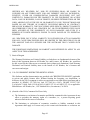
AWOS
900 Series
Remote Maintenance
Monitoring (RMM)
Software
Version 4.0
User's Manual
M595141
All Weather Inc. • 1165 National Drive • Sacramento, CA 95834 • 800.824.5873 • www.allweatherinc.com
M595141-001
REV.A
Contents
REMOTE MAINTENANCE MONITORING (RMM)
1
OVERVIEW
SYSTEM REQUIREMENTS
RMM MAIN SCREEN
RMM FILE STRUCTURE
1
1
2
3
RMM SETUP
4
INSTALLING A MODEM IN WINDOWS
INSTALLING THE RMM SOFTWARE
CONFIGURING THE MODEM
"DIALING FROM"
"CONNECT USING"
SETTING SYSTEM PARAMETERS
GENERAL PARAMETERS
AUTO-DIAL PARAMETERS
4
4
5
5
7
8
8
9
THE RMM SITE LIST
11
CREATING A SITE LIST
EDITING THE SITE LIST
SORTING THE SITE LIST
COPYING THE SITE LIST TO ANOTHER COMPUTER
11
13
13
14
USING RMM
15
AUTOMATIC AND MANUAL DIALING
ENABLING AUTO-DIALING
ENABLING AUTO-DIALING FOR SITES
ENABLING SYSTEM AUTO-DIALING AND SETTING THE AUTO-DIAL PARAMETERS
AUTO-DIALING SESSIONS
VIEWING FILES
SESSION FILES
SITE FILES
MANUAL DIALING
REMOTE FUNCTIONS
HANG UP
15
15
15
15
16
16
17
25
31
32
37
ALL WEATHER, INC. SOFTWARE END USER LICENSE AGREEMENT
38
Page iii
M595141-001
REV.A
Remote Maintenance Monitoring (RMM)
Overview
A valuable feature of All Weather Inc.'s 900 and 3000 Series AWOS Central Data Processor (CDP)
Models 2090, 2090-B, and 3000 is their built-in Remote Maintenance Monitoring (RMM)
capability. RMM enables a remote computer to access an AWOS' CDP via modem and, using All
Weather Inc.'s Windows®-based RMM software, to set system parameters, view system status and
data, and download data and error logs. The RMM software allows manual or automatic dialing of
sites, and provides menu links to file viewing functions that allow downloaded files to be accessed
easily from the main screen for viewing or printing without exiting the RMM program. Other menu
options provide links to configuration settings and manual dialing functions from the main RMM
screen (Figure 1).
System Requirements
•
•
•
•
•
•
•
Pentium/Celeron 1.0 GHz or higher processor
128 MB RAM minimum, 256 MB recommended
Super VGA(800x600) video adapter
Windows® XP, Service Pack 2
100 MB hard disk space for each AWOS to be monitored
CD-ROM Drive
V.90 56 KB internal or external modem
Page 1
M595141-001
REV.A
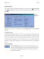
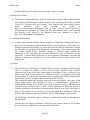
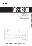
Menu Bar
Site List
Auto-Dial
status panel
Site list
editing controls
Text Buffer
Status Bar
Figure 1
Main RMM screen.
RMM Main Screen
The RMM Main Screen (Figure 1) consists of a menu bar, site list, site list editing controls, autodial status panel, text buffer, and status bar.
•
The menu bar provides access to all the RMM software's setup functions, file viewing
options, and manual dialing functions. The menus are explained in detail in the relevant
sections throughout this manual.
•
The site list contains the list of sites routinely dialed from this location. This is one of the
linchpins of the auto-dialing function, and is explained in detail along with the site list
editing controls, in the RMM Site List chapter.
•
The auto-dial status panel shows the current status of the Auto-Dial function (enabled or
disable), and shows the programmed auto-dial start time (if enabled). During an auto-dial
session, this panel shows the progress and status of the session.
Page 2
M595141-001
•
REV.A
The text buffer displays any messages from the remote site during either auto-dialing or
manual dialing. During an auto-dial session, the connection status for each site and the
progress of the automated RMM functions for that site will be displayed here. During a
manual dial session, requested reports (such as the one-minute data report and current status
report) are displayed. The buffer will hold 512 lines before it becomes full. Once it's full,
the oldest half of the buffer (the first 256 lines) will be deleted, and new text will be
appended to the end.
•
During operation, status messages (such as the progress of a dialing attempt) are displayed
in the status bar incorporated into the lower right corner of the main screen frame. Status
messages remain visible until replaced by a new message.
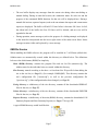
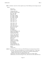
RMM File Structure
When installing the RMM software, the program will be installed in C:\AWI\rmm (default dir).
Subdirectories are automatically created within this directory as defined below. The definitions
below use the default name (RMM) for simplicity.
Main (RMM) directory: contains the program files and site list file (rmmsites.cfg). The
subdirectories for the individual sites are created within this directory.
Site directory: named according to the three- or four-letter Site ID specified when adding the
site to the site list (see Page 11). (For example: RMM\QMF). This directory contains the
site's configuration file ("current.cfg"), as well as the previous configuration file
("previous.cfg"), if the configuration has been changed (see Page 19).
Errlog directory: a subdirectory of the site directory; contains all the downloaded ERRLOG
files for the site (see Page 25).
Printer directory: a subdirectory of the site directory; contains all the downloaded PRINTER
files for the site (see Page 29).
Reports directory: a subdirectory of the main (RMM) directory; contains the downloaded Call
Summary Reports and Error Summary Reports (see Pages 17 through 25).
A typical RMM directory would look like this:
Page 3
M595141-001
REV.A
RMM Setup
Installing a Modem in Windows
Before performing any RMM tasks, the RMM computer must have a modem installed and
working. This is done within Windows, and may already be in place. To check whether a modem is
installed:
1
From the Windows task bar's StartÆControl Panel
2
Double-click the Phone and Modem Options icon. Select the Modems tab at the top. A
screen will be displayed showing the installed modems. If no modems are listed, click the
Add... button.
3
Follow the directions on the screen to use the Windows Hardware Installation Wizard. This
program will automatically detect an installed modem and add the necessary files to the
operating system. You may be prompted to insert the Windows CD or disks, or to insert the
modem manufacturer's driver disk.
4
If you are installing a new modem card or connecting a new external modem to the RMM
computer, follow the instructions included with the modem for installing the modem and
drivers.
Installing the RMM Software
To install the RMM software, follow the steps below. (Note: Each AWOS site called will require
200 Kbytes of disk space per day for data files. We recommend that at least 2 GB of free disk
space be available on the installation drive.)
1
Insert the M469059 CD into the CD-ROM.
2
From Windows (using Explorer or My Computer), double-click the file on the M469059
CD named M595141-060.exe. The RMM Setup program will start automatically.
3
Follow the directions given on-screen by the Setup program until installation is complete.
Page 4
M595141-001
REV.A
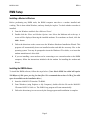
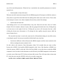
Configuring the Modem
When the RMM Program is started, the Configure Modem screen (Figure 2) is automatically
presented, allowing you to specify modem and line connection settings. In most cases, once these
settings have been specified it should not be necessary to change them. If you do need to change
something, you can access the Configure Modem menu at any time from within the RMM software
as follows:
1
Select Modem... from the Configuration menu on the RMM main screen's menu bar. The
Configure Modem screen (Figure 2) will appear.
Figure 2
Configure
Modem
Screen
"Dialing From"
The Dialing From panel lets you specify general settings for the RMM computer's modem
connection, such as location name and dialing properties.
1
The current dialing location is shown in the Your Location window of the Dialing From
panel. (Note: A location named New Location, with default dialing settings, is automatically
created by Windows when a modem is first installed.) If more than one location profile has
Page 5
M595141-001
REV.A
been created, you can select a different location from the drop-down list that appears when
you click the arrow to the right of the Your Location box.
2
Select the location profile to be used for RMM, then click Dialing Properties.
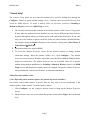
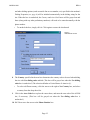
3
The Phone and Modem Options screen will be shown with a list of locations. Select the
location you want to edit or select New to create a new location. The Dialing Properties
screen (Figure 3) allows you to specify a location name, set dialing rules (whether to dial 9,
etc.), and enter a calling card number for charge calls.
Figure 3
Dialing Properties screen.
4
To change the name of the selected location, click the name to highlight it, then type a new
name.
5
The remaining Dialing Properties settings will vary from location to location. Specify the
settings as required for your location, then click OK.
Page 6
M595141-001
REV.A
"Connect Using"
The Connect Using panel lets you select the modem to be used for dialing and, through the
Configure... button, to specify modem settings. (Note: A modem cannot be installed directly from
within the RMM software. To install a modem, follow the directions provided in Installing a
Modem in Windows found in the RMM Setup section).
1
The currently selected modem is shown in the Modem window of the Connect Using panel.
If more than one modem has been installed, you can select a different one from the dropdown list that appears when you click the arrow to the right of the Modem box. If you want
only your active modem to appear on the list, delete any other modems (Standard Modem,
for example) using the Remove function on the Modems control panel (Start Menu Æ
Control Panel Æ Modems).
2
Select the modem to be used for RMM.
3
To access the Modem Properties screen for the selected modem (to change modem
connection settings, adjust the speaker volume, etc.), click Configure.... The Modem
Properties screen is part of Windows, and a link is provided from within the RMM software
simply for convenience. The Modem Properties are set to default values for a specific
modem during modem installation (see Installing a Modem in Windows found in the RMM
Setup section) and should not normally need to be changed. For specific Modem Properties
setting information, consult your Windows or modem documentation.
Setting the modem speaker volume
(Note: Depending on the modem software, this feature may not be available.)
One feature found within Modem Properties that you may want to access periodically is the
modem speaker volume control. To set the speaker volume:
1. Click Configure... on the Configure Modem screen to bring up the Modem Properties
screen.
2. On the Modem Properties screen, adjust the speaker volume slider (Figure 4) to the desired
level.
Page 7
M595141-001
REV.A
Figure 4
Setting the speaker volume
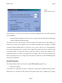
Setting System Parameters
A final configuration screen allows you to set up several general parameters governing connection
to AWOS stations. These are primarily timing functions that are useful in fine-tuning RMM for
reliable connection. The System Parameters screen (Figure 5) is divided into two panels: The
General panel lets you set the length of time to wait before attempting to send RMM commands to
the station, and to set the maximum length of time to wait for a response from the AWOS before
declaring a time-out condition; the Auto-Dial Parameters panel lets you change settings specific to
auto-dial sessions, and to turn auto-dialing on or off.
General Parameters
The settings found in the System Parameters General panel let you:
•
Set the time delay between initiation of dialing and sending of the command for the AWOS
to enter RMM mode
This can be set to any value between 10 and 60 seconds. The default setting is 20 seconds. This has
been found to be a reliable setting for most installations, allowing sufficient time for a connection
to be made before entering RMM mode. In rare cases (where the time required to make a
connection is especially long) this may need to be set to a higher value. Be cautious, however,
Page 8
M595141-001
REV.A
Figure 5
System Parameters screen
about setting it to a lower value, since this may not allow enough time for a successful connection
to be established.
• Set the maximum amount of time to wait for a response from the AWOS before declaring a
time-out condition and disconnecting
This can be set to any value between 5 and 60 seconds. The default value for this setting is 30
seconds. This can be set to a higher value if an AWOS repeatedly fails to respond to an RMM
command within the allotted time. It can also be set to a lower value, but it is recommended to
leave some margin and not try to set this value too tight. The response time from an AWOS station
is normally around 5 seconds, but factors beyond the software's control can sometimes cause
transmission times to be slowed. Leaving this set to a higher value will not delay connection or
affect processing in any way. It simply sets a time limit for connection, so that the RMM program
does not wait indefinitely.
Auto-Dial Parameters
The settings found in the System Parameters Auto-Dial Parameters panel let you:
•
Enable auto-dialing
Click this box to enable (box checked) or disable (box unchecked) the RMM Auto-Dial feature.
When this box is checked, the other options in this panel become active, enabling you to change
Page 9
M595141-001
REV.A
any of the auto-dial parameters. When the box is unchecked, the auto-dial parameters are inactive
(grayed-out).
•
Set the number of auto-dial retries
When an auto-dial connection attempt fails, the RMM program will attempt to redial the station as
many times as specified in this field after first dialing all the other sites on the site list. This is done
in an attempt to contact a site whose telephone line was busy on the first attempt.
•
Set the auto-dial start time
Auto-dialing can be set to start automatically at any time. Enter the start time value in 24-hour
format (22:00, for instance, denotes 10 pm), either by typing the desired time or by clicking the up
or down arrows to the right of the box. Clicking the up arrow will increment the time, while
clicking the down arrow decrements it. (To change the time rapidly using the arrows, hold the
mouse button down.)
The auto-dial start time is used as the start time for all downloads during an auto-dial session,
even though a specific site may not actually be dialed until some time later.
•
Set the time difference allowed between the RMM computer and the remote station's clock
before resetting the remote station's clock
Set this value to the amount of time discrepancy (from 5-60 seconds) that you want to allow
between the AWOS's clock and the RMM computer's clock. One of the functions of RMM is to
check the remote AWOS's clock and, if the clock has drifted, to reset the time to match the RMM
computer's clock. In order for this function to work effectively, the RMM computer's clock must be
set to the correct Zulu time (UTC) before each auto-dial session. This will ensure that an inaccurate
PC clock does not cause the AWOS's clock to be set to the wrong time.
NOTE: USE CAUTION WHEN ADJUSTING THIS SETTING.
Page 10
M595141-001
REV.A
The RMM Site List
Creating a Site List
The most common use of RMM is to call a list of AWOS sites automatically each day to check
operation of the sites. The first step in automating RMM functions, then, is creating this list of
sites.
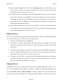
The top portion of the main screen shows the site list and provides the three buttons (Add,
Modify, and Delete) used in creating and editing the list (see Figure 6).
Figure 6
Site List
Auto-Dial On/Off checkbox
To create a new site entry:
1
Click the Add... button to the right of the site list window. The Add New Site screen (Figure
7) will be displayed.
2
The cursor will automatically be positioned in the ID text entry box in the Identifier panel
of the Add New Site screen. You may immediately begin entering the three-to-four character
Site ID in the box.
3
After entering the Site ID, hit the Tab key on the keyboard to move the cursor to the Name
box.
4
Enter a name to identify the site, using up to 31 characters.
5
Hit the Tab key to move the cursor to the State box.
6
Enter the two-letter abbreviation for the state in which the AWOS is located.
7
The lower panel on the Add New Site screen (Number To Call) is used to enter the AWOS
site’s RMM telephone number. The first field in the panel, the checkbox labeled Use
dialing rules, is checked by default. When this box is checked, the country code, area code,
Page 11
M595141-001
REV.A
and other dialing options (such as outside line access number, etc) specified in the modem's
Dialing Properties (see page 6) will be included automatically in the dialing string for the
site. When the box is unchecked, the Country and Area Code boxes will be grayed out and
these (along with any other preliminary numbers) will need to be entered manually with the
phone number.
•
To uncheck the box, simply click it. Click again to restore the checkmark.
Figure 7
Add New Site screen
8
The Country specified in the next box determines the country code to be used when dialing
the site with Use dialing rules enabled. (This box will be grayed out when the Use dialing
rules box is unchecked.) The selection defaults to United States of America (1).
•
To select a different country, click the arrow to the right of the Country box, and select
a country from the drop-down list.
9
Click in the Area Code box to place the cursor there, and enter the area code of the AWOS
site, if necessary. (This box will be grayed out when the Use dialing rules box is
unchecked.)
10 Hit Tab to move the cursor to the Phone Number box.
Page 12
M595141-001
REV.A
11 Enter the phone number of the site. If the Use dialing rules box is unchecked, you will
have to enter the number in its entirety, including area code (if necessary) and any other
preliminary numbers (outside line access, etc.).
12 To enable this site for auto-dialing, click the checkbox labeled Tag this site for automatic
dialing. This selection can be changed at any time from the main screen by checking or
unchecking the Auto-Dial On/Off checkbox for that site (found at the start of the site’s
entry on the site list⎯see Figure 6). A checkmark enables auto-dialing, an unchecked box
omits the site from auto-dial sessions.
13 When all the information is entered and correct, click OK. You will be returned to the main
screen, and the new site will be added to the site list. To exit without saving the information
and without adding the site to the list, click Cancel.
Editing the Site List
The site list can be edited at any time using the Modify and Delete buttons, found to the right of the
site list on the main screen. To edit or delete a site from the list:
1
Click the site ID on the site list to highlight it.
2
To edit the site, click the Modify button. The Modify Site screen will appear. This screen
contains the same fields as the Add New Site screen, and shows the current settings for the
selected site.
3
Change any of the settings by clicking in the desired text box and editing the information as
necessary. When the information is correct, click OK to return to the main screen. The new
information will be shown in the site’s entry on the site list.
4
To delete a site, click Delete. An alert screen will be displayed asking you to confirm that
you want to delete the site from the list. If you do, click Yes to delete the site. To return to
the main screen without deleting the site, click No.
Sorting the Site List
By default, the site list is sorted based on the Site ID, in ascending alphabetical order (A, B, C,
etc.). The sorting method can be changed at any time by clicking any of the column headings on the
site list (ID, Name, State, or Phone Number). Clicking a heading will cause the entries to be
sorted by that field in ascending order. Clicking the same heading a second time will sort the
Page 13
M595141-001
REV.A
entries in descending order (Z, Y, X, etc.). The order in which the sites are sorted is also used as the
dialing order in auto-dial mode.
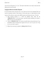
Copying the Site List to Another Computer
If several locations will be using the same or very similar site lists, the site information does not
need to be manually entered at each location. It can be entered once at a single location, and the
master site file can then be copied to other RMM computers and edited as necessary. To do this:
1
Using Windows Explorer or a similar file handling utility, locate the file
"RMMSITES.CFG", in the main directory (specified during installation, the default is
rmm), and copy it to a removable disk.
2
Copy the "RMMSITES.CFG" file from the removable disk to the main directory of any
other RMM computer to duplicate the original site list. (Note: This will replace the existing
site list on the target computer.)
3
Edit the list as necessary as explained in Editing the Site List above.
Page 14
M595141-001
REV.A
Using RMM
Automatic and Manual Dialing
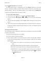
The most common use of RMM is to call a list of AWOS sites automatically each day to check
operation of the sites. During an auto-dial session status information, configuration information,
current data, and error logs are collected for each site and saved to the RMM computer’s hard disk.
When necessary—when RMM could not contact a station during auto-dial, for instance—stations
can be manually dialed using the RMM software. A series of remote functions are available during
manual dialing that allow the user to collect a full set of information for the site, as well as to
change configuration settings and investigate reported errors.
Enabling Auto-Dialing
Enabling auto-dialing involves two steps:
1
Enabling auto-dialing for each site
2
Enabling system-wide auto-dialing and setting the auto-dial parameters
Enabling Auto-Dialing for Sites
To enable a site for auto-dialing, its Auto-Dial On/Off checkbox (see Figure 6) on the site list must
be checked. To disable auto-dialing for a site, uncheck this box. You can also enable or disable
auto-dialing for a site using the Tag this site for automatic dialing option when creating or editing a
site.
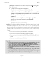
Enabling System Auto-Dialing and Setting the Auto-Dial Parameters
Before the sites enabled for auto-dialing can be automatically dialed, system-wide auto-dialing
must be enabled and the auto-dial parameters set. This is done through the System Parameters
screen (Figure 5), found on the Configuration menu.
1 From the Configuration menu, select System Parameters.
2
Enable auto-dialing by checking the Enable Auto-Dialing checkbox in the Auto-Dial
Parameters panel of the System Parameters screen.
Page 15
M595141-001
3
REV.A
If you have not already done so, set the auto-dial parameters as required for your location.
(Refer to the Auto-Dial Parameters section of the RMM Setup chapter of this manual for
detailed explanations of these options.)
Auto-Dialing Sessions
(Note: When connecting to a site, the voice broadcast will be heard until, after a few seconds, the
modems establish a connection.)
During an RMM auto-dial session, several things happen:
•
A log of all errors reported over the past two days is downloaded from the site and saved to
the RMM computer's hard disk.
•
A copy of the AWOS data for the past two days is saved in a file in the same format as the
AWOS printer output.
Note: It may take up to 10 minutes per site to download all the data files.
•
The station's status report is checked for errors since the last status reset, and all detected
errors are compiled in the Error Summary Report.
•
The status report is reset.
•
The time and date registered on the AWOS clock is synchronized to the RMM computer's
clock.
•
The site's configuration file is checked, and if it has changed since the last RMM download,
a copy of the new configuration is downloaded.
Several files are created during the session and are saved to the RMM computer's hard disk.
These files can be divided into two groups: Session Files and Site Files.
Viewing Files
(Note: Log details may differ between the AWOS 900 and AWOS 3000 Series. The examples
shown here are for an AWOS 900.)
Session Files and Site Files are normally opened automatically by either Notepad or Wordpad
(utilities included with Windows) after being selected from the file list as described in the
following sections. If desired, these files can also be opened as text files in Microsoft Word or
another word processing application. To open a file:
1
Select Open from the application's pull-down menu (normally the File menu).
Page 16
M595141-001
2
REV.A
Navigate through the file list to the directory containing the desired file (see page 3 for file
locations).
3
In the "files of type" box on the file list screen, select "All Files (*.*)".
4
Highlight the desired file, then click Open. The file naming convention for each type of file
is explained in the section below covering that type of file (Call Summary Report, Error
Summary Report, ERRLOG file, or PRINTER file).
Session Files
Session Files collate the results of an entire auto-dial session into a single file, and contain
information on each of the sites dialed. Two Session Files are created during each auto-dial session:
•
Call Summary Report
•
Error Summary Report
These files can be opened using the File menu's View option.
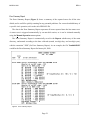
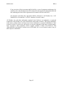
Call Summary Report
The Call Summary Report (Figure 8) shows the results of the auto-dial session, indicating which of
the sites was successfully reached, and which (if any) could not be reached. If a site could not be
reached, you will generally want to dial that site manually and download the collected information
Figure 8 Call Summary Report
Page 17
M595141-001
REV.A
using the Manual Operation menu commands.
The Call Summary Report is automatically saved in the Reports subdirectory of the main
directory, and named according to the date collected (month, two-digit day, and two-digit year),
with the extension ".CSR" (for Call Summary Report). As an example, the file "Jan0400.CSR"
would be the Call Summary Report for January 04, 2000.
To view the Call Summary Report:
1
From the main screen's File menu, select View Call Summary Reports.
2
A file list will open in the Reports directory showing a list of all saved Call Summary
Reports.
3
Select the desired file, highlight it, and click Open. Double-clicking the file name will also
open it.
4
The file will be opened in the Notepad application, if size permits. If the file is too large to
be opened by Notepad, a prompt will appear asking if you want to use Wordpad to open the
file. Click Yes.
Interpreting the Call Summary Report
The Call Summary Report is organized in a tabular format, and summarizes the results of the RMM
session for each site dialed.
Time shows the time at which the site was dialed.
Site ID is the AWOS site ID of the site dialed.
Call Status indicates whether a successful connection was made, and reads either CONNECT
or one of the following messages. If any of these messages is shown, the site should be
dialed manually.
BUSY indicates a busy signal was received from the site and no connection was
made.
NOANSWER indicates that the site did not respond, no carrier was detected.
DISCONNECT will be shown if the call was disrupted during the RMM session.
NOMODEMAVAIL is shown if the RMM computer could not detect its modem. If
this message is received, check the modem setup using the Modem... option on
the Configuration menu.
Page 18
M595141-001
REV.A
Update D/T indicates whether the site's date and/or time was updated to correspond with the
RMM computer's clock. If T is shown, the AWOS clock differed from the RMM
computer's clock by at least the amount specified in the Time drift field on the System
Parameters screen, and the AWOS clock was reset. If D is shown, the AWOS's date was
changed to agree with the RMM computer's. If both the date and time were changed, D/T
will be shown. If neither the date nor time was changed, the field will be blank.
The remaining fields in the report provide information on retrieved information (Status Report,
Configuration Report, PRINTER file, and ERRLOG file).
Status Report: The first two Retrieved Information fields concern the Status Report:
Rtrvl Error will show an S if there was an error retrieving the Status Report. If the data
was retrieved successfully, the field will be blank. When an error is reported, you will
usually want to dial the site manually to download the status information.
# of Errors Found shows the total number of errors reported for the site since the last
status reset. This number will agree with the number of errors shown in the Error
Summary Report.
Config Report: The next two Retrieved Information fields concern the Config Report, which is
a check of the site's configuration file. This file contains the AWOS site's basic configuration
information, including Site ID, Magnetic Declination, BP Sensor Offsets, and other parameters.
RMM checks this configuration file to see whether it has changed since the last RMM session.
If the file has changed, the RMM software will download the new configuration and save it in
the site's dedicated directory (for example, Rmm\QMF\) as "current.cfg". It will save the old
configuration in the file "previous.cfg". When the Configuration Report shows the
configuration as having changed, these two files can be compared to see what changes were
made.
Rtrvl Error will show a C if there was an error retrieving the Configuration Report. If the
data was retrieved successfully, the field will be blank. When an error is reported, you
may want to dial the site manually to verify that the site's configuration has not
changed unexpectedly.
Data Mod'ed will show CfgMod if the site's configuration file has been changed since the
last RMM session. If the file was not changed, the field will be blank. When the
configuration file has changed, you can compare the old ("previous.cfg") and new
Page 19
M595141-001
REV.A
("current.cfg") configurations to see what has changed using the File menu's View
Other Files command.
1
Click the desired site on the site list to highlight it.
2
From the main screen's File menu, select View Other Files.
3
A file list will open in the selected site's directory. Select the "current.cfg" file,
highlight it, and click Open. Double-clicking the file name will also open it. The
file will be opened in the Notepad application.
4
Print the file.
5
Again go to the main screen's File menu and select View Other Files.
6
Navigate to the site's directory and locate the file "previous.cfg".
7
Open the file.
8
Print the file and compare it to "current.cfg".
Prntr/Errlog: The final two Retrieved Information fields show retrieval errors for the
PRINTER and ERRLOG files. These two files contain error and sensor data from the
previous two days. The first column shows any errors in retrieving the files for the first day
(Ystrdy) and the second column shows any errors in retrieving the files for the second day
(Today).
•
If an error occurred retrieving the PRINTER file, P will be shown.
•
If an error occurred retrieving the ERRLOG file, E will be shown.
•
If an error occurred retrieving both the PRINTER and ERRLOG files, P/E will be
shown.
•
If no errors occurred the columns will be blank.
Usage Tips
•
•
•
•
•
Examine the Call Summary Report following every auto-dial session. If any sites could
not be reached, dial them manually using the Manual Operation menu commands.
A quick glance at the Call Summary Report will tell you which sites reported errors, so
you will likely only need to view the ERRLOGs for those sites.
If a Status Report retrieval error is reported, you can dial the site manually to retrieve the
information.
If a Configuration Report retrieval error is reported, you may want to dial the site
manually to check that the configuration file has not changed unexpectedly.
If the configuration file is reported as having changed, compare the current.cfg and
previous.cfg files in the site's directory to see what the changes were.
Page 20
M595141-001
REV.A
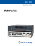
Error Summary Report
The Error Summary Report (Figure 9) shows a summary of the reported errors for all the sites
dialed, and is useful for quickly scanning for any potential problems. For a more detailed history of
a specific site's operation, refer to the site's ERRLOG file.
The data in the Error Summary Report represents all errors reported since the last status reset.
A status reset is triggered automatically by an auto-dial session, or it can be initiated manually
using the Manual Operation menu options.
The Error Summary Report is automatically saved in the Reports subdirectory of the main
directory, and named according to the date collected (month, two-digit day, and two-digit year),
with the extension ".ESR" (for Error Summary Report). As an example, the file "Jan0400.ESR"
would be the Error Summary Report for January 04, 2000.
Figure 9 Error Summary Report
Page 21
M595141-001
REV.A
To view the Error Summary Report:
1
From the main screen's File menu, select View Error Summary Reports.
2
A file list will open in the Reports directory showing a list of all saved Error Summary
Reports.
3
Select the desired file, highlight it, and click Open. Double-clicking the file name will also
open it.
4
The file will be opened in the Notepad application, if size permits. If the file is too large to
be opened by Notepad, a prompt will appear asking if you want to use Wordpad to open the
file. Click Yes.
Interpreting the Error Summary Report
The Error Summary Report contains status information for all the sites dialed. Each site's report is
tagged by the time at which the report was generated (time of RMM connection to that site) and the
Site ID. Any of the following messages may be displayed.
Status accumulated since shows the time at which the displayed status information began
accumulating. This is also the time of the last status reset.
Minutes of no DCP comm shows the amount of time during which there was no
communication between the CDP and DCP.
DCP Comm CRC Errors shows the percentage of communication errors recorded for packets
transmitted from the DCP to the CDP. A percentage greater than 5% indicates a
communication problem that should be investigated.
Hours of no ADAS comm shows the amount of time during which there was no
communication between the CDP and ADAS.
Restarts shows the number of times the DCP and/or CDP have been restarted since the data
began accumulating.
CDP shows the amount of time during which the CDP was in any of these modes: Test Mode,
Inoperative Mode, or Manual Mode.
Sensor Missing--a missing entry is included for any installed sensor that has been reported as
missing during the period covered by the report,. The entry shows the total amount of time
over which the sensor was reported as missing since the data began accumulating. The BP
Sensor entry also includes the reported current temperature at the sensors, along with the
Page 22
M595141-001
REV.A
minimum and maximum reported temperatures.
Day/Night Changes will only be shown when no Day/Night changes have been reported since
the last status reset.
DCP: If DCP errors have been reported, any of the following error messages may be displayed:
Not Reporting
Restart
MaintSw
0Vref
2.5Vref
5Vref
FanFail
ROMerr
RAMerr
WDRefHi
WDRefLo
NoComm (followed by the name of the sensor—Vis or Chi—with which there is a
communication problem)
VIS: If visibility sensor errors have been reported, any of the following messages may be
shown:
Not Reporting
Config-Error
3-Hd-Op (8364-E only)
Dirty-Windows
Data-Misg
NVRam
Mode0Dir
Mode0Ind
Mode1Dir
Mode1Ind
E0
E1
D0
D1
CrossChk
E0-Heater
E1-Heater
D0-Heater
D1-Heater
Aux-Heater
CtlrPwrSup
Page 23
M595141-001
REV.A
CHI: If ceilometer errors have been reported, any of the following error messages may be
shown:
Mode Error
LOW TX PWR
UNBAL DETECTO
OFFSET IN DETECTOR
REF VOLT ERR
ZERO PT FAIL
HI CURR IN S BRD
HI CURR IN M BRD
HI CURR IN H BRD
VOLT FAIL +24V
VOLT FAIL +5V
VOLT FAIL +15V
VOLT FAIL -15V
VOLT FAIL +230
VOLT FAIL +10V
VOLT FAIL -10V
ADC FAIL IN H BRD
RX HI VOLT FAIL
TEMP FAIL
OVERHEAT
OUT PWR FAIL
LASER CIR CHRGE FAIL
IPEAK CIRC ERROR
LASER HV REG FAIL
IPEAK CURR ERROR
LASER HV REG FAIL
LASER HV CIRC FAIL
RECVR FAIL
DET FAIL
ADDR FAUL S BRD
ADDR FAULT H BRD
LPF MISSING
SYNC MISSING
LASER TRIGGER FAIL
MASTR SLAV COM FAIL
RESET
NotReporting
ADAS: If an ADAS error has occurred, any of the following error messages may be shown:
DiscMode—this means no SNRM was received from ADAS since a CDP restart;
the poll code may be incorrect, or there may be an ADAS communication
problem: check “hours of no ADAS comm” entry
NoALDARS—this means no lightning data has been received from ADAS
OMOnotSent (one-minute message not sent)—this can occur when ADAS does not
Page 24
M595141-001
REV.A
ask for the one-minute message, or if there is an intermittent communications
problem
HdlcConfigErr—HDLC card internal error, firmware or hardware fault
HdlcH/Werr—HDLC card internal error, firmware or hardware fault
HdlcXmitErr—HDLC card internal error, firmware or hardware fault
CDP: If CDP errors have been reported, any of the following error messages may be shown:
VoiceCardErr
ArchiveError
DiskError
Usage Tips
•
•
Examine the Error Summary Report following every auto-dial session for a summary of
all the errors reported for all the sites since the last RMM session. For sites showing
many errors, go to the ERRLOG for that site to examine it more closely.
When sensors are reported missing, check whether any CDP restarts have occurred.
Sensors will be reported missing for a length of time following a restart, with the length
of time varying depending on the sensor. The wind speed and direction sensors will be
missing for only 2-3 minutes, for instance, while the ceilometer will go missing for
about 20 minutes with each restart.
Site Files
Site Files contain information for a single site only. Four Site Files are created for each site during
an auto-dial session:
•
ERRLOG file for yesterday
•
ERRLOG file for today
•
PRINTER file for yesterday
•
PRINTER file for today
These files can be opened using the File menu's View Archived Filesoption.
ERRLOG
The ERRLOG files provide a detailed record of reported errors for a single selected site. The
ERRLOG files are automatically saved in the Errlog subdirectory of the site's dedicated directory.
Page 25
M595141-001
REV.A
To view the ERRLOG for a site:
1
Click the site's name on the site list to select it. (The ERRLOG viewing option below will
not be available unless a site is selected.)
2
From the main screen's File menu, select View Archived FilesERRLOG.
3
A file list will open in the site's Errlog directory showing a list of all saved ERRLOGs for
the selected site. The files are named by the date collected (month, two-digit day, and twodigit year). As an example, the file "Jan0400" would be the ERRLOG for January 04, 2000.
4
Select the desired file, highlight it, and click Open. Double-clicking the file name will also
open it.
5
The file will be opened in the Notepad application, if size permits. If the file is too large to
be opened by Notepad, a prompt will appear asking if you want to use Wordpad to open the
file. Click Yes.
Interpreting the ERRLOG - 2090 Series AWOS
The ERRLOG file (Figure 10) is divided into separate entries collected at 20-minute intervals,
each of which contains a catalogue of status messages concerning the site's operation. The first line
of each entry shows the time at which the data was collected, followed by the latest status message
(refer to the AWOS CDP User's Manual to decode this message) and the AWOS's operational
mode. The status messages that follow this header are described below.
Last System Restart shows the date and time the CDP was last restarted.
Last DCP Restart shows the date and time the DCP was last restarted.
Last DCP Maint Sw shows the date and time the DCP maintenance switch was last pressed.
Comm shows the current status of the communication link to the DCP; should normally read
“OK”.
Telephone call counter shows the number of incoming calls (both voice and RMM) received.
HDLC Data Link shows the HDLC link’s status (OK or error), mode (Disconnect or Normal),
transmissions sent (weather data), and transmissions received (lightning data).
Page 26
M595141-001
REV.A
Figure 10 ERRLOG file
Minutes of no DCP communication shows the number of minutes elapsed since the last packet
was received from the DCP.
If data could not be processed for a sensor, even momentarily, during the 20-minute interval,
$Missing will be displayed, followed by the name(s) of the sensor(s). Note that there are a
number of reasons why a sensor might be reported missing (sensor taken offline or a CDP
restart, for example) other than a sensor failure.
DCP shows the status of the DCP; should normally read “OK”.
PRW shows the status of the present weather sensor (if installed); should normally read “OK”.
VIS shows the status of the visibility sensor; should normally read “OK”.
CHI shows the status of the ceilometer; should normally read “OK”.
BP Temp/Min/Max shows the BP sensor’s last measured temperature, as well as the minimum
and maximum temperatures measured since startup.
Rain shows the accumulated rainfall since midnight. If no rainfall has been measured, this line
will not be shown.
Page 27
M595141-001
REV.A
Day/Night shows the current state reported by the Day/Night Sensor. If a Day/Night sensor
error has been detected, Day-night sensor error will be shown.
Five second DCP data shows the instantaneous data received from the DCP before processing
by the CDP.
One minute processed data shows the most recent one-minute data after processing by the
CDP.
Usage Tips
•
Use the ERRLOG to examine the history of reported errors to differentiate between
intermittent operation and failure of a sensor or component.
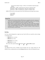
Interpreting the ERRLOG - 3000 Series AWOS
The ERRLOG file (Figure 11) contains alarm information about the system. Each time an alarm is
created, acknowledged, or deleted, it is captured in this log file. The information in the file is stored
as comma separated text. The header is described below.
Figure 11 ERRLOG
Page 28
M595141-001
REV.A
Site Identifier shows the site name
Alarm Name shows the name of the alarm.
Type shows type of alarm, either warning or error depending upon the severity.
State shows the state of the alarm, either pending or acknowledged
Active shows weather the alarm is active or not, either true or false. If the alarm is not active,
then the last state is shown in the State field.
Message gives a short description of why the alarm was triggered.
PRINTER
The PRINTER file contains AWOS data reports for a single selected site. The data is in the same
format as that output to the AWOS CDP printer, and consists of a compilation of data records for
one day beginning at 00:00. The PRINTER files are automatically saved in the Printer
subdirectory of the site's dedicated directory.
To view the PRINTER file for a site:
6
Click the site's name on the site list to select it. (The PRINTER viewing option below will
not be available unless a site is selected.)
7
From the main screen's File menu, select View Archived FilesPRINTER.
8
A file list will open in the site's Printer directory showing a list of all saved PRINTER files
for the selected site. The files are named by the date collected (month, two-digit day, and
two-digit year). As an example, the file "Jan0400" would be the PRINTER file for January
04, 2000.
9
Select the desired file, highlight it, and click Open. Double-clicking the file name will also
open it.
10 The file will be opened in the Notepad application, if size permits. If the file is too large to
be opened by Notepad, a prompt will appear asking if you want to use Wordpad to open the
file. Click Yes.
Interpreting the PRINTER File
The PRINTER file is essentially a duplicate of the data output to the AWOS CDP's printer at the
site, and may be a large file. Each data record within the file is contained on a single line, and may
include the following information. (NOTE: that some information will not be displayed if the
sensor is not installed at the site.)
Page 29
M595141-001
REV.A
•
Airport Identifier
•
Julian Day
•
Zulu Time (HHMM)
•
Wind Direction/Speed and Gust (degrees magnetic and knots)
•
Visibility (statute miles, if 836x series sensor is installed)
•
Lightning at airport or in vicinity (TS or VCTS, if lightning sensor is installed or data
available from ALDARS)
•
Sky Condition (if 8339 series ceilometer is installed)
•
Temperature/Dew Point Temperature (Celsius)
•
Altimeter Setting (inches of Mercury)
•
Density Altitude (feet, only if >= 1000 feet above airport elevation)
•
Variable Visibility (statute miles, if 836x series visibility sensor is installed)
•
Variable Wind Direction (magnetic degrees)
•
Precipitation Accumulation
•
Day/Night sensor output
•
System status codes
Usage Tips
•
If a sensor malfunction is suspected, use the PRINTER file to compare the values
reported by the sensor over time. If the values do not change as they should, or if they
change erratically, the sensor may need to be checked in the field.
Page 30
M595141-001
REV.A
Manual Dialing
Manual Dialing provides a backup dialing method for the customary auto-dial method, and
provides a way to perform RMM functions outside the regular schedule of auto-dial sessions. It
allows spot-checking of individual sites where problems are suspected, and provides a series of
maintenance and configuration functions that can be carried out remotely at any time.
To manually dial a site:
1
Highlight the site on the site list that you want to call. If you want to call a site that is not
part of the site list, go directly to step 2.
2
Select Dial... from the Manual Operation menu.
3
The Dialing Options screen will appear. This screen is identical to the Configure Modem
screen (see page 5), but with the Calling panel active. If you are calling a site selected from
the site list, all the necessary dialing information will be filled in automatically. If you are
calling a site not shown on the site list, fill in the necessary dialing information. To use the
dialing preferences specified earlier through the Dialing Properties screen (see page 5),
make sure the Use dialing rules checkbox is checked. Unchecking this box will disable the
Country and Area Code fields, and you will have to enter the complete phone number
directly in the Phone Number field (including "9," for an outside line (if necessary), the
country code, are code, and phone number).
4 Click Dial to dial the number. (Note: When connecting to a site, the voice broadcast will be
heard until, after a few seconds, the modems establish a connection.)
5
As the call is being made, status messages will appear at the bottom of the main screen.
Once a connection is made (or if it fails), a message will be displayed in the text buffer (see
Figure 1) that makes up the lower half of the main screen. This text buffer is where all
responses from the AWOS are displayed during manual dialing.
Once a connection has been made, you can perform any of the remote functions discussed in
the following sections.
Page 31
M595141-001
REV.A
Remote Functions
The functions available during RMM manual dialing are accessed from the Manual Operation
menu's Remote Functions... option. Selecting this option calls up the RMM Functions screen
(Figure 12).
Figure 12
RMM Functions
screen
The RMM Functions screen is divided into two panels: Non-Restricted functions and Restricted
functions.
Non-Restricted Functions
The Non-Restricted functions allow you to view the current sensor data, the current status report,
and the current configuration. Selecting any of these options will display the requested data in the
main screen's text buffer. You can also reset the status report from this panel. None of the AWOS's
operational settings (configuration, date, time, BP offsets), however, can be changed using these
functions; to do that requires password access to the Restricted functions (via the Log On...
button).
Get Current Report
Get Current Report displays the most recent one-minute data message in the
text buffer. This message follows the same format as the PRINTER file. Refer to
the description of the PRINTER file (page 29) for the meaning of each of the
fields shown in the message.
Page 32
M595141-001
REV.A
Get Status Report
Get Status Report displays the most recent Status Report in the text buffer. The
Status Report shows the current status of the site, and combines elements of the
Error Summary Report and the ERRLOG file. Refer to those two sections (pages
21 through 29) for a description of each of the status fields shown.
Get Config.
Clicking Get Config. will display the current configuration of the AWOS in the
text buffer. The displayed information includes:
•
•
•
•
•
•
•
•
•
•
•
Station Name
Airport ID
AWOS type
Site configuration
Field elevation, feet above MSL
BP sensor elevation(s), feet above MSL
Magnetic deviation
Runway number(s) where DCP(s) installed
BP sensor offsets, inHg x 1000
HDLC hex address (ADAS link)
CDP software version number
Log On
The Log On button calls up a user logon screen for accessing the Restricted
Functions. Enter your password in the Password box, and click OK to activate
the Restricted Functions. (Note: If a password is not entered after two minutes,
the CDP will disconnect.)
Page 33
M595141-001
REV.A
Restricted Functions
Once you have entered your password at the RMM Functions screen as explained above (see Log
On), the buttons in the Restricted Functions panel become active. These buttons allow you to
view data, to download data, and to change certain of the AWOS's operating parameters.
System Date/Time
The buttons in the System Date/Time panel let you check or set the date and time on the AWOS
CDP clock.
Displays the current date (as registered by the AWOS CDP) in the text buffer.
Calls up a screen allowing you to reset the date on the AWOS CDP.
1
At the Set Date screen, enter the new date you want the AWOS CDP's clock
to read.
2
Click OK to confirm the new date and set the AWOS CDP clock..
Displays the current time (as registered by the AWOS CDP) in the text buffer.
Calls up a screen allowing you to reset the time on the AWOS CDP.
3
At the Set Date screen, enter the new time you want the AWOS CDP's clock
to read.
4
Click OK to confirm the new time and set the AWOS CDP clock..
Sensors
The Sensors panel contains two buttons that let you check the sensor on/off configuration (Get
Status) and turn sensors on or off (Configure...). The VHF radio voice output can also be turned
on or off using this function.
Displays the current sensor on/off configuration in the text buffer.
Calls up a screen (Figure 13) allowing you to set the on/off status of sensors at
the site. This Set Sensors... screen shows a list of all the sensors installed at the
site, along with the choices "On-Line" and "Off-Line" in the screen's upper panel.
To set any of the listed sensors on-line or off-line, follow the steps below.
Page 34
M595141-001
REV.A
5
In the Sensor: panel, click the desired sensor to highlight it. Note that the
VHF Radio Voice is one of the available selections, allowing you to turn the
voice radio output on or off remotely.
6
To set the on-line or of-line state of the sensor, click the appropriate choice
in the Set: panel.
7
Click OK to set the sensor's state to the new setting. To exit without
changing the sensor's state, click Cancel.
8
Only one sensor at a time can be configured through the Set Sensor... screen.
To configure another sensor, select Configure... again from the RMM
Functions screen and repeat the above steps.
Figure 13
Set Sensor On/Off screen
BP Offsets
The BP Offsets panel contains two buttons that let you check the barometric pressure sensors'
offset values (Get Offsets) and change those values (Set Offsets...). Note: This feature will not
work in the 3000 Series AWOS or with MetObserver.
Displays the barometric pressure sensors' current offset values in the text buffer.
Calls up a screen (Figure 13) allowing you to set the barometric pressure sensors'
offset values. This Set Offsets... screen provides two input boxes, one for BP
Sensor 1, and one for BP Sensor 2. To enter an offset value for either of the
sensors, follow the steps below.
Page 35
M595141-001
REV.A
1
Click to place the cursor in the appropriate input box (BP1 or BP2).
2
The default offset is 0, which is automatically entered in both input boxes.
To enter a new value, delete the 0 and enter the new value.
3
Click OK to set the sensors' offsets to the new values. To exit without
changing the offsets, click Cancel.
Figure 13
Set BP Offsets screen
Reset Status Report
Clicking Reset Status Report will reset all the status flags, and status will begin
accumulating anew. In subsequent status reports, the Status accumulated since
field will show the time of this reset. Before resetting the status report, be sure
that any reported errors have been noted and investigated.
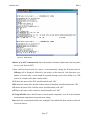
Retrieve Files
The final of the Restricted Functions options is Retrieve File.... This option
allows you to retrieve two types of files that are normally retrieved during an
auto-dial session: The ERRLOG file contains status information compiled at
twenty-minute intervals; the PRINTER file contains the accumulated weather
data records. For detailed explanations of the content of these two files, refer to
ERRLOG on page 26, and PRINTER on page 29.
Page 36
M595141-001
REV.A
Figure 14
Filie Retrieval screen
To retrieve either of these files, follow the steps below.
1
Click the radio button to the left of the file you want to retrieve to select it.
2
Enter the date for which you want to retrieve data. To do this, click the arrow
to the right of the File Date: input box. A calendar will appear, with today's
date circled and selected. To select a different day, click the desired day on
the calendar. To move to a different month, click the arrows in either upper
corner of the calendar. The left arrow will call up the previous month's
calendar; the right arrow will call up the next month's calendar.
3
Click OK to begin the download.
4
Once the download is complete, an alert window will appear telling you the
name of the saved file and its location on your hard drive.
Hang Up
When you've completed the necessary RMM functions for a site, disconnect from the site by
selecting Hang Up from the Manual Operation menu.
Page 37
M595141-001
REV.A
ALL WEATHER, INC. SOFTWARE END USER LICENSE
AGREEMENT
THIS SOFTWARE END USER LICENSE AGREEMENT (THIS “AGREEMENT”) IS DATED
FOR REFERENCE PURPOSES ONLY AS OF MARCH 26, 2009, AND IS BY AND BETWEEN
ALL WEATHER, INC., A DELAWARE CORPORATION, AND LICENSEE.
IMPORTANT: THIS AGREEMENT IS A LEGAL AGREEMENT BETWEEN LICENSEE AND
ALL WEATHER, INC. READ IT CAREFULLY BEFORE COMPLETING THE
INSTALLATION PROCESS AND USING THE SOFTWARE. IT PROVIDES A LICENSE TO
USE THE SOFTWARE AND CONTAINS WARRANTY INFORMATION AND LIABILITY
DISCLAIMERS. BY SELECTING THE DOWNLOAD OR INSTALL NOW BUTTON AND/OR
USING THE SOFTWARE, YOU ARE CONFIRMING YOUR ACCEPTANCE OF THE
SOFTWARE AND AGREEING TO BECOME BOUND BY THE TERMS OF THIS
AGREEMENT. IF YOU DO NOT AGREE TO BE BOUND BY THESE TERMS, THEN DO
NOT INSTALL OR USE THE SOFTWARE.
1) Definitions
a) "Authorized Operating Systems" means versions of the following operating systems:
i) Microsoft Windows operating systems including Windows 95, 98, 2000, NT, ME, XP
Home, XP Professional, and XP Tablet PC Edition, but specifically excluding Windows
XP Embedded, Windows XP Media Center Edition, and successors;
ii) Linux operating systems, but specifically excluding any embedded version of Linux
b) "All Weather, Inc." means All Weather, Inc., a Delaware corporation and its affiliates,
subsidiaries and licensors, if any.
c) "Software" means only the StormFront™, AWI Engine and third party software programs,
in each case, supplied by All Weather, Inc. therewith, and corresponding documentation,
associated media, printed materials, and online or electronic documentation, and all updates
or upgrades of the above that are provided to Licensee.
d) For the avoidance of doubt, no embedded or device versions of the above operating
systems, or any other operating systems, are included as Authorized Operating Systems.
2) License Grants
a) All Weather, Inc. hereby grants to Licensee the revocable, personal, non-exclusive and
nontransferable right to install and activate the Software solely for Licensee’s use in its own
business in strict conformance with the terms and conditions of this Agreement. Licensee
may install and use the Software on a single desktop or laptop computer that runs an
Page 38
M595141-001
REV.A
Authorized Operating System. A license for the Software may not be shared, installed or
used concurrently on different computers.
b) Licensee agrees that All Weather, Inc. may audit Licensee’s use of the Software for
compliance with these terms at any time, upon reasonable notice. In the event that such
audit reveals any use of the Software by Licensee other than in full compliance with the
terms of this Agreement, Licensee shall reimburse All Weather, Inc. for all reasonable
expenses related to such audit in addition to any other liabilities Licensee may incur as a
result of such non-compliance.
3) License Restrictions
a) Licensee shall not use the Software on any non-PC product or any embedded or device
versions of the above operating systems, including, but not limited to, (A) mobile devices,
set top boxes (STB), handhelds, phones, web pads, tablets and Tablet PCs that are not
running Windows XP Tablet PC Edition, game consoles, TVs, DVD players, media centers
(including Windows XP Media Center Edition and its successors), electronic billboards or
other digital signage, internet appliances or other internet-connected devices, PDAs,
medical devices, ATMs, telematic devices, gaming machines, home automation systems,
kiosks, remote control devices, or any other consumer electronics device, (B) operatorbased mobile, cable, satellite, or television systems, (C) other closed system devices, or (D)
any operating system that is not an Authorized Operating System.
b) Licensee shall not make or distribute copies of the Software, or electronically transfer the
Software from one computer to another or over a network.
c) Licensee shall not alter, merge, modify, adapt or translate the Software, or decompile,
reverse engineer, disassemble, or otherwise reduce the Software to a human-perceivable
form.
d) Licensee shall not sell, rent, lease, or sublicense the Software.
e) Licensee shall not modify the Software or create derivative works based upon the Software.
f) Licensee shall not export the Software into any country prohibited by the United States
Export Administration Act and the regulations thereunder.
g) In the event that Licensee fails to comply with this Agreement, All Weather, Inc. may
terminate the license and Licensee must immediately return to All Weather, Inc. all copies
of the Software and all accompanying items (with all other rights of both parties and all
other provisions of this Agreement surviving any such termination).
h) Licensee shall not use the Software to develop any software or other technology having the
same primary function as the Software, including but not limited to using the Software in
any development or test procedure that seeks to develop like software or other technology,
or to determine if such software or other technology performs in a similar manner as the
Page 39
M595141-001
REV.A
Software.
4) Ownership
The foregoing license gives Licensee limited license to use the Software. All Weather, Inc. and
its suppliers retain all right, title and interest, including all copyright and intellectual property
rights, in and to, the Software and all copies thereof. All rights not specifically granted in this
Agreement, including Federal and International Copyrights, are reserved by All Weather, Inc.
and its suppliers.
5) WARRANTY DISCLAIMER
ALL WEATHER, INC. PROVIDES NO TECHNICAL SUPPORT, WARRANTIES OR
REMEDIES FOR THE SOFTWARE.
ALL WEATHER, INC. AND ITS SUPPLIERS DISCLAIM ALL WARRANTIES AND
REPRESENTATIONS, WHETHER EXPRESS, IMPLIED, OR OTHERWISE, INCLUDING
THE WARRANTIES OF MERCHANTABILITY OR FITNESS FOR A PARTICULAR
PURPOSE. ALSO, THERE IS NO WARRANTY OF NON-INFRINGEMENT AND TITLE
OR QUIET ENJOYMENT. ALL WEATHER, INC. DOES NOT WARRANT THAT THE
SOFTWARE IS ERROR-FREE OR WILL OPERATE WITHOUT INTERRUPTION. NO
RIGHTS OR REMEDIES REFERRED TO IN ARTICLE 2A OF THE UCC WILL BE
CONFERRED ON LICENSEE UNLESS EXPRESSLY GRANTED HEREIN. THE
SOFTWARE IS NOT DESIGNED, INTENDED OR LICENSED FOR USE IN HAZARDOUS
ENVIRONMENTS REQUIRING FAIL-SAFE CONTROLS, INCLUDING WITHOUT
LIMITATION, THE DESIGN, CONSTRUCTION, MAINTENANCE OR OPERATION OF
NUCLEAR FACILITIES, AND LIFE SUPPORT OR WEAPONS SYSTEMS. ALL
WEATHER, INC. SPECIFICALLY DISCLAIMS ANY EXPRESS OR IMPLIED
WARRANTY OF FITNESS FOR SUCH PURPOSES.
IF APPLICABLE LAW REQUIRES ANY WARRANTIES WITH RESPECT TO THE
SOFTWARE, ALL SUCH WARRANTIES ARE LIMITED IN DURATION TO NINETY (90)
DAYS FROM THE DATE OF DELIVERY.
NO ORAL OR WRITTEN INFORMATION OR ADVICE GIVEN BY ALL WEATHER,
INC., ITS DEALERS, DISTRIBUTORS, AGENTS OR EMPLOYEES SHALL CREATE A
WARRANTY OR IN ANY WAY INCREASE THE SCOPE OF ANY WARRANTY
PROVIDED HEREIN.
ALL WEATHER, INC. SHALL HAVE NO RESPONSIBILITY IF THE SOFTWARE HAS
BEEN ALTERED IN ANY WAY, OR FOR ANY FAILURE THAT ARISES OUT OF USE
OF THE SOFTWARE WITH OTHER THAN A RECOMMENDED HARDWARE
CONFIGURATION, PLATFORM OR OPERATING SYSTEM.
6) LIMITATION OF LIABILITY
Page 40
M595141-001
REV.A
NEITHER ALL WEATHER, INC. NOR ITS SUPPLIERS SHALL BE LIABLE TO
LICENSEE OR ANY THIRD PARTY FOR ANY INDIRECT, SPECIAL, INCIDENTAL,
PUNITIVE, COVER OR CONSEQUENTIAL DAMAGES (INCLUDING, BUT NOT
LIMITED TO, DAMAGES FOR THE INABILITY TO USE EQUIPMENT OR ACCESS
DATA, LOSS OF BUSINESS, LOSS OF PROFITS, BUSINESS INTERRUPTION OR THE
LIKE), ARISING OUT OF THE USE OF, OR INABILITY TO USE, THE SOFTWARE AND
BASED ON ANY THEORY OF LIABILITY INCLUDING BREACH OF CONTRACT,
BREACH OF WARRANTY, TORT (INCLUDING NEGLIGENCE), PRODUCT LIABILITY
OR OTHERWISE, EVEN IF ALL WEATHER, INC. OR ITS REPRESENTATIVES HAVE
BEEN ADVISED OF THE POSSIBILITY OF SUCH DAMAGES AND EVEN IF A
REMEDY SET FORTH HEREIN IS FOUND TO HAVE FAILED OF ITS ESSENTIAL
PURPOSE.
ALL WEATHER, INC.'S TOTAL LIABILITY TO LICENSEE FOR ACTUAL DAMAGES
FOR ANY CAUSE WHATSOEVER WILL BE LIMITED TO THE GREATER OF $10 OR
THE AMOUNT PAID BY LICENSEE FOR THE SOFTWARE THAT CAUSED SUCH
DAMAGE.
THE FOREGOING LIMITATIONS ON LIABILITY ARE INTENDED TO APPLY TO ALL
ASPECTS OF THIS AGREEMENT.
7) Basis of Bargain
The Warranty Disclaimer and Limited Liability set forth above are fundamental elements of the
basis of this Agreement between All Weather, Inc. and Licensee. All Weather, Inc. would not
be able to provide the Software on an economic basis without such limitations. Such Warranty
Disclaimer and Limited Liability inure to the benefit of All Weather, Inc.'s licensors and
successors and assigns.
8) U.S. GOVERNMENT RESTRICTED RIGHTS LEGEND
This Software and the documentation are provided with "RESTRICTED RIGHTS" applicable
to private and public licenses alike. Without limiting the foregoing, use, duplication, or
disclosure by the US Government is subject to restrictions as set forth in this Agreement and as
provided in DFARS 227.7202-1(a) and 227.7202-3(a) (1995), DFARS 252.227-7013
(c)(1)(ii)(OCT 1988), FAR 12.212(a)(1995), FAR 52.227-19, or FAR 52.227-14, as applicable.
Manufacturer: All Weather, Inc., 1165 National Drive, Sacramento, CA 95834.
9) (Outside of the USA) Consumer End Users Only
a) The limitations or exclusions of warranties and liability contained in this Agreement do not
affect or prejudice the statutory rights of a consumer, i.e., a person acquiring goods
otherwise than in the course of a business.
b) The limitations or exclusions of warranties, remedies or liability contained in this
Agreement shall apply to Licensee only to the extent such limitations or exclusions are
Page 41
M595141-001
REV.A
permitted under the laws of the jurisdiction where Licensee is located.
10) Third Party Software
a) The Software contains third party software, which requires notices and/or additional terms
and conditions. Such third party software includes, but is not necessarily limited to, Apache
Version 2.0, JGoodies-Looks and jcalendar. Such required third party software notices
and/or
additional
terms
and
conditions
are
located
at
http://www.allweatherinc.com/thirdparty/ and are made a part of and incorporated by
reference into this Agreement. By entering into this Agreement, Licensee is also accepting
and agreeing to be bound by the additional terms and conditions set forth at
http://www.allweatherinc.com/thirdparty/.
11) Confidential Information
a) Licensee agrees that the Software contains proprietary information, including trade secrets,
know-how and confidential information that are the exclusive property of All Weather, Inc.
During the period this Agreement is in effect and at all times after its termination, Licensee
and its employees and agents shall maintain the confidentiality of this information and not
sell, license, publish, display, distribute, disclose or otherwise make available this
information to any third party nor use such information except as authorized by this
Agreement. Licensee shall not disclose any such proprietary information concerning the
Software to persons not an employee of Licensee without the prior written consent of All
Weather, Inc.
12) General
a) The internal laws of the State of California shall govern this Agreement, without giving
effect to principles of conflict of laws. Licensee hereby consents to the exclusive
jurisdiction and venue of the state courts sitting in Sacramento County, California or the
federal courts in the Northern District of California to resolve any disputes arising under
this Agreement. In each case this Agreement shall be construed and enforced without regard
to the United Nations Convention on the International Sale of Goods.
This Agreement contains the complete agreement between the parties with respect to the
subject matter hereof, and supersedes all prior or contemporaneous agreements or
understandings, whether oral or written. Licensee agree that any varying or additional terms
contained in any purchase order or other written notification or document issued by
Licensee in relation to the Software licensed hereunder shall be of no effect. The failure or
delay of All Weather, Inc. to exercise any of its rights under this Agreement or upon any
breach of this Agreement shall not be deemed a waiver of those rights or of the breach.
No All Weather, Inc. dealer, agent or employee is authorized to make any amendment to
this Agreement.
Licensee may not assign or sublicense, without the prior written consent of All Weather,
Inc., which may be withheld in its sole and absolute discretion.
Page 42
M595141-001
REV.A
If any provision of this Agreement shall be held by a court of competent jurisdiction to be
contrary to law, then that provision will be enforced to the maximum extent permissible and
the remaining provisions of this Agreement will remain in full force and effect.
All questions concerning this Agreement shall be directed to: All Weather, Inc., 1165
National Drive, Sacramento, CA 95834, Attention: General Counsel.
All Weather, Inc. and other trademarks contained in the Software are trademarks or registered
trademarks of All Weather, Inc. in the United States and/or other countries. Third party trademarks,
trade names, product names and logos may be the trademarks or registered trademarks of their
respective owners. Licensee may not remove or alter any trademark, trade names, product names,
logo, copyright or other proprietary notices, legends, symbols or labels in the Software. This
Agreement does not authorize Licensee to use All Weather, Inc.'s or its licensors' names or any of
their respective trademarks.
Page 43
All Weather Inc.
1165 National Drive
Sacramento, CA 95834
800.824.5873
916.928.1000
Fax: 916.928.1165
www.allweatherinc.com
M595141-001
Revision A
ECO 1875
September, 2009