1
Manual No. '03 • FDU -T-077
TECHNICAL MANUAL
Collection data
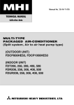
HIGH STATIC PRESSURE DUCT TYPE
PACKAGED AIR-CONDITIONER
(Split system, Air to air heat pump type)
FDUP808HES-S, FDUP1008HES-S
-
3-
CONTENTS
1 GENERAL INFORMATION............................................................................. 1
1.1 Specific features ...................................................................................... 1
1.2 How to read the model name .................................................................. 1
2 SELECTION DATA ......................................................................................... 2
2.1 Specifications .......................................................................................... 2
2.2 Range of usage & limitations ................................................................. 4
2.3 Exterior dimensions ................................................................................ 5
2.4 Exterior appearance ................................................................................ 8
2.5 Piping system .......................................................................................... 8
2.6 Selection chart ......................................................................................... 9
2.7 Characteristics of fan .............................................................................. 11
2.8 Noise level ................................................................................................ 12
3 ELECTRICAL DATA ....................................................................................... 13
3.1 Electrical wiring ....................................................................................... 13
4 OUTLINE OF OPERATION CONTROL BY MICROCOMPUTER .................. 14
5 APPLICATION DATA ...................................................................................... 24
5.1 Installation of indoor unit........................................................................ 25
5.2 Installation of remote controller ............................................................. 28
5.3 Installation of outdoor unit ..................................................................... 29
6 MAINTENANCE DATA ................................................................................... 32
1 GENERAL INFORMATION
1.1 Specific features
(1) Less refrigerant charge amount due to use of double phase refrigerant flow system. The total refrigerant charge amount has been
reduced by more than 50%.
(2) The indoor outdoor interconnection signal wiring has been done away with. The microcomputer chip is installed in the indoor
unit. There is no need for the unit to communicate between the outdoor and indoor units so the unit is more resistant to
electromagnetic noise thus the incidence of microcomputer malfunction has been reduced. The compressor in the outdoor unit
has its own self protection function, that reacts according to abnormal high pressure and excessive high temperature.
(3) There are only five power lines between the outdoor and indoor unit, As no signal wire is used there is no need to separate the
power line from the signal line. One cab tyre cable with 6 wires encased in one sheath is enough for conducting the wiring work
between the outdoor unit and the indoor unit. This contributes to simpler wiring work in the field.
(4) The controls are wired residential split air conditioner type remote controller with 6 malfunction modes.
(5) All models have service valves protruding from the outdoor unit for faster flare (liquid side) and brazing (gas side) connection
work in the field.
(6) Operation noise has been drastically reduced by increasing the number of high performance fans and by through sound insulation.
(7) When installing, the optimum outside static pressure can be set using the fan controller.
(8) With the height of all equipment made uniform at 360mm and neatly installed into the ceiling, the installation of equipment with
different capacities into the same ceiling space is made easy.
1.2 How to read the model name
Example: FDU
P
80
8
H
ES-S
Applicable power source ... See the specifications
Heat pump type
Series No.
Product capacity
R407C models
Model name
-1-
FDU: High static pressure duct type wired remote
controller
FDC: Outdoor unit
2 SELECTION DATA
2.1 Specification
Model FDUP808HES-S
FDUP808HES-S
Model
Item
FDU808-A
Nominal cooling capacity(1)
W
Nominal heating capacity(1)
W
FDCP808HES3
20000
22400
Power source
Operation data(3)
Cooling input
Running current (Cooling)
Power factor (Cooling)
3 Phase, 380/415V 50Hz
kW
8.9/9.1
A
16.3/16.6
%
83/76
kW
7.9/8.0
Running current (Heating)
A
13.5/13.7
Power factor (Heating)
%
89/81
Inrush current (L.R.A)
A
Heating input
Noise level
Exterior dimensions
Height × Width × Depth
Net weight
99
dB(A)
48
58
mm
360 × 1570 × 830
1450 × 1350 × 600
kg
92
195
–
CB90H × 1
Refrigerant equipment
Compressor type & Q’ty
–
6.5
–
Line starting
Heat exchanger
Louver fines & inner grooved tubing
Slitted fines & bare tubing
Refrigerant control
Capillary tube
Motor
kW
Starting method
Capillary tube
Refrigerant
R407C
Quantity
Refrigerant oil
kg
–
r
–
4.95 [Pre-charged up to the piping length of 5m]
4.4 (MA32R)
Defrost control
MC controlled de-icer
High pressure control
High pressure switch
Air handling equipment
Multiblade centrifugal fan × 4
Fan type & Q’ty
Motor
200 × 2
100 × 2
Line starting
Line starting
CMM
51
180
Pa
Standard: 100, Max: 200
–
Available
–
W
Starting method
Air flow (Standard)
Available static pressure
Fresh air intake
Air filter, Q’ty
Shock & vibration absorber
Electric heater
–
Rubber sleeve (for fan motor)
Rubber mount (for compressor)
–
70 (Crank case heater)
Remote control switch
Operation switch
(Optional: RCD-H-E)
Room temperature control
–
Internal thermostat for fan motor.
Internal thermostat for fan motor
Frost protection thermostat.
High pressure protection switch
mm
Liquid line: φ12.7 (1/2″) Gas line: φ25.4 (1″)
(in)
Connecting method
Drain hose
– (Indoor unit side)
Thermostat by electronics
Safety equipment
Refrigerant piping size
Field purchased
W
Operation control
Installation data
Propeller fan × 2
Brazing
Liquid line: Flare Gas line: Brazing
(Connectable with VP25)
Insulation for piping
–
Necessary (both Liquid & Gas lines)
Accessories
Mounting kit.
Optional parts
–
Notes (1) The data are measured at the following conditions.
Item
Indoor air temperature
Operation
DB
WB
Cooling
27˚C
19˚C
Heating
20˚C
–
Outdoor air temperature
DB
WB
35˚C
24˚C
7˚C
6˚C
(2) This packaged air-conditioner is manufactured and tested in conformity with the following standard.
ISO-T1 “UNITARY AIR-CONDITIONERS”
(3) The operation data indicate when the air-conditioner is operated at 380V 50Hz/415V 50Hz respectively.
-2-
Standards
ISO-T1, JIS B8616
Model FDUP1008HES-S
FDUP1008HES-S
Model
Item
FDU1008-A
Nominal cooling capacity(1)
W
Nominal heating capacity(1)
W
FDCP1008HES3
25000
28000
Power source
Operation data(3)
Cooling input
Running current (Cooling)
Power factor (Cooling)
3 Phase, 380/415V 50Hz
kW
13.0/13.2
A
21.9/21.1
%
90/87
kW
11.8/11.9
Running current (Heating)
A
20.3/19.6
Power factor (Heating)
%
88/85
Inrush current (L.R.A)
A
Heating input
Noise level
Exterior dimensions
Height × Width × Depth
Net weight
154
dB(A)
49
58
mm
360 × 1570 × 830
1450 × 1350 × 600
kg
92
205
–
CB125H × 1
Refrigerant equipment
Compressor type & Q’ty
–
9.0
–
Line starting
Heat exchanger
Louver fines & inner grooved tubing
Slitted fines & bare tubing
Refrigerant control
Capillary tube
Motor
kW
Starting method
Capillary tube
Refrigerant
R407C
Quantity
Refrigerant oil
kg
–
r
–
7.1 [Pre-charged up to the piping length of 5m]
4.4 (MA32R)
Defrost control
MC controlled de-icer
High pressure control
High pressure switch
Air handling equipment
Multiblade centrifugal fan × 4
Fan type & Q’ty
Motor
230 × 1, 270 × 1
100 × 2
Line starting
Line starting
CMM
68
180
Pa
Standard: 100, Max: 200
–
W
Starting method
Air flow (Standard)
Available static pressure
Fresh air intake
Available
–
Field purchased
–
Rubber sleeve (for fan motor)
Rubber mount (for compressor)
–
70 (Crank case heater)
Air filter, Q’ty
Shock & vibration absorber
Electric heater
W
Operation control
Remote control switch
Operation switch
(Optional: RCD-H-E)
Room temperature control
Refrigerant piping size
–
Internal thermostat for fan motor.
Internal thermostat for fan motor
Frost protection thermostat.
High pressure protection switch
mm
Liquid line: φ15.88 (5/8″) Gas line: φ28.58 (1 1/8″)
(in)
Connecting method
Drain hose
– (Indoor unit side)
Thermostat by electronics
Safety equipment
Installation data
Propeller fan × 2
Brazing
Liquid line: Flare Gas line: Brazing
(Connectable with VP25)
Insulation for piping
–
Necessary (both Liquid & Gas lines)
Accessories
Mounting kit.
Optional parts
–
Notes (1) The data are measured at the following conditions.
Item
Indoor air temperature
Operation
DB
WB
Cooling
27˚C
19˚C
Heating
20˚C
–
Outdoor air temperature
DB
WB
35˚C
24˚C
7˚C
6˚C
(2) This packaged air-conditioner is manufactured and tested in conformity with the following standard.
ISO-T1 “UNITARY AIR-CONDITIONERS”
(3) The operation data indicate when the air-conditioner is operated at 380V 50Hz/415V 50Hz respectively.
-3-
Standards
ISO-T1, JIS B8616
2.2 Range of usage & limitations
Models
All models
Item
Indoor return air temperature
(Upper, lower limits)
Refer to the selection chart
Outdoor air temperature
(Upper, lower limits)
Indoor unit atmosphere (behind ceiling)
temperature and humidity
Dew point temperature: 28˚C or less, relative humidity: 80% or less
Max. 50m
Refrigerant line (one way) length
Max. 30m(Outdoor unit is higher)
Vertical height difference between
outdoor unit and indoor unit
Max. 15m(Outdoor unit is lower)
Rating ± 10%
Power source voltage
Voltage at starting
Min. 85% of rating
Frequency of ON-OFF cycle
Max. 10 times/h
ON and OFF interval
Max. 3 minutes
-4-
2.3 Exterior dimensions
(1) Indoor unit
Models FDU808-A, 1008-A
60
13
138
Holes for screw
(M5 × 20 pcs.)
Control box
808: ø25.4 (1")
1008: ø28.58 (1 1/8")
35
VIEW A
13
25
510
Hole for wiring
(ø25)
106 (Low of suspension leg)
45
Low
185
170
200
13
13
530
6 × 200 = 1200
138
1450 (Duct for dimension)
60
138
Drain (VP25)
(Natural drainage)
60
900 or more
Inspection hole
(900 × 1730)
100 or more
35
900 or more
300
or more
Space for installation and service
Inspection hole
(600 × 600)
Installation
space
900
Slab
Ceiling
Service
space
35
100
Installation hole
(Service space of side)
60
200
or more
Service
space
400 or more
Piping space
(Service space of lower)
-5-
77
30
310
A
360
49
Upper
138
80
25
Supply air
13
Hole for screw
(M5 × 20 pcs.)
138
Suspension bolts
(M10 × 4 pcs.)
250 (Duct for dimension)
808: ø12.7 (1/2")
1008: ø15.88 (5/8")
163
60
95
25
35
Gas piping
13
200
6 × 200 = 1200
1500 (Duct for dimension)
163
Liquid piping
Return air duct
13
138
13
65
80
100
1570
250 (Duct for dimension)
18
1640 (Suspension bolts pitch)
1690
25
830
794 (Suspension bolts pitch)
18
(2) Remote controller (Optional parts)
Wall
0.3mm2, 3cores (O.D.φ5.6)
Wire
(Recessed)
LCD display
Electrical box
(Locally Purchased)
120
16
Remote controller mounting dimensions
120
60
46
47
17
7
120
89
83.5
For the passage
after wiring
Notes (1) Allowable length of remote controller
cable: 600 m
Allowable rang of wire thickness and length
Standard Within 0.3 mm2
0.5 mm2
0.75 mm2
1.25 mm2
2 mm2
Remote controller outline
-6-
× Within 100 m
× Within 200 m
× Within 300 m
× Within 400 m
× Within 600 m
50
1450
Connect of liquid piping
808: ø12.7 (1/2")
1008: ø15.58 (5/8")
(
)
Opening for
exit gas pipimg
(ø39)
170
157
Opening for
exit wiring
(ø50)
80
Connect of gas piping
102
Power supply connecting
terminal block
105
105
119
20
291.5
Opening for
exit piping
(ø88)
Models FDCP808HES3, 1008HES3
Opening for
exit wiring
(ø50)
80
Opening for
exit liquid
pipimg
(ø25)
22
29
170
ø25.4 (1")
( 1008:808:ø28.58
(1 1/8") )
Opening for
exit piping
(ø88)
Wall Height H3
532
640
175
123
240
15
Rear surface
Connect of liquid piping
808: ø12.7 (1/2")
1008: ø15.88 (5/8")
(
)
702
283.5
Connect of
gas piping
808: ø25.4 (1")
1008: ø28.58 (1 1/8")
(
)
110
175
100
70
Hole for drain
(ø50)
567
283.5
135
Hole for drain
(8-ø20)
L4
Service
( space
)
395
169
81
123
Opening for exit
gas pipimg
(ø65)
88
110
L2
Wall height H1
Wall height H4
Downward outlet hole for
piping and wiring
157
767
L1
40
suction
250
850
Wall height H2
250
15
Anchor bolts
(M10 × 4pcs.)
L3
(Unit:mm)
Opening for
exit liquid piping
(ø50)
Opening for
exit wiring
(ø35)
50
-7-
Dimentions of refrigerant piping
connecting mouth
(Front)
Installation
example
Dimensions
L1
L2
L3
L4
H1
H2
H3
H4
I
II
III
Open
0
Open
500
0
0
300
300
300
Open
500
0
1000 or less
Not limited Not limited Not limited
Not limited Not limited 700 or less
Not limited Not limited
Notes (1) Make sure to secure the unit with anchor bolts.
(2) When the strong wind blows, place the unit so that discharge outlet
faces the wind direction with right angle.
(3) Make sure to allow the space of 1 m or more above the unit.
(4) Connect the refrigerant piping (both gas side and liquid side) at local
site.
(5) If the wall height H1, H3 of installation example III exceeds the
limited value, make sure the value of L1, L3 are to be as follows.
L1 =H1 -500
L3 = 300 + (H3-700) / 2, however, if L3 exceeds 600, there is no
limit for the wall height H3.
(3) Outdoor unit
1350
600
2.4 Exterior appearance
(1)
Indoor unit ····· Zinc steel plate
(2) Outdoor unit
Models FDCP808HES3,1008HES3
Polar white
2.5 Pipng system
Models FDUP808HES-S,1008HES-S
Cooling cycle Outdoor unit
Heating cycle
Indoor unit
Service valve
(Brazing)
High pressure switch(63H2)
(For fan motor control)
Thermistor
(ThO-A)
Brazing
Strainer
Gsa line
808 : ø25.4
(1008
: ø28.58 )
4way valve
Thermistor
(ThI-A)
Heat
exchanger
High pressure
switch(63H1)
(For protection)
Heat
exchanger
Lower
Upper
Muffler
Thermistor
(ThI-R)
Muffler
Compressor
Solenoid
valve
(SV)
Capillary tube
Liquid line
Brazing
Thermistor (ThO-R)
Capillary tube
Check valve
808 : ø12.7
(1008
: ø15.88 )
Strainer
Accumlator
Service valve
(Flare connecting)
Capillary tube
Preset point of the protective devices
Parts name
Thermistor
(for protection overloading in heating)
Mark
ThI-R
Equipped
unt
All models
OFF68°C
ON61°C
Indoor unit
Thermistor
(for frost prevention)
OFF2.5°C
ON10°C
Thermistor
(for detecting heat
exchange temp.)
ThO-R
Outdoor unit
OFF70°C
ON60°C
High pressure switch
(for controlling FMO)
63H2
Outdoor unit
OFF 2.79 MPa
ON 2.26 MPa
High pressure switch
(for Protection)
63H1
Outdoor unit
OFF 3.24 MPa
ON 2.65 MPa
-8-
2.6 Selection chart
Correct the cooling and heating capacity in accordance with the conditions as follows. The net cooling and heating capacity can be
obtained in the following way.
Net capacity = Capacity shown on specification × Correction factors as follows.
Cooling operation
Outdoor air D.B.
temperature (˚CD.B.)
Coefficient of cooling and heating capacity
in relation to temperatures
Coefficient of cooling and heating capacity in relation to temperatures
Heating operation
Indoor air D.B.
temperature (˚CD.B.)
(1)
Indoor air W.B. temperature (˚CW.B.) ISO-T1 Standard condition
Outdoor air W.B. temperature (˚CW.B.) ISO-T1 Standard condition
Table of bypass factor
Model
Item
Air flow
Upper limit
Standard
Lower limit
FDUP808HES-S
FDUP1008HES-S
0.015
0.033
0.049
0.032
0.050
0.060
-9-
(2) Correction of cooling and heating capacity in relation to air flow rate control (fan speed)
Coefficient: 1.00 at High, 0.95 at Low
(3) Correction of cooling and heating capacity in relation to one way length of refrigerant piping
It is necessary to correct the cooling and heating capacity in relation to the one way equivalent piping length between the indoor
and outdoor units.
Equivalent piping length(1) m
7.5
Heating
1.0
1.0
1.0
Cooling
1.0
0.995
0.985
10
15
20
25
30
35
40
1.0
1.0
0.998
0.998
0.99
0.975
0.965
0.955
0.945
0.935
45
50
55
0.993
0.988
0.988
0.925
0.915
0.905
Note (1) Equivalent piping length can be obtained by calculating as follows.
808 [ø25.4 (1")]: Equivalent piping length = Real piping length + (0.40 × Number of bends in piping)
1008 [ø28.58 (1'/8")]: Equivalent piping length = Real piping length + (0.45 × Number of bends in piping)
[Equivalent piping length < Limitation length of piping + 5 m]
(4) When the outdoor unit is located at a lower height than the indoor unit in cooling operation and when the
outdoor unit is located at a higher height than the indoor unit in heating operation, the following values should be
subtracted from the values in the above table.
Height difference between the indoor unit and
outdoor unit in the vertical height difference
5m
10 m
15 m
20m
25 m
30 m
Adjustment coefficient
0.01
0.02
0.03
0.04
0.05
0.06
Piping length limitations
Model
All models
Item
Max. one way piping length
50 m
Max. vertical height difference
Outdoor unit is higher 30m, Outdoor unit is lower 15m
Note (1) Values in the table indicate the one way piping length between the indoor and outdoor units.
How to obtain the cooling capacity
Example: The net cooling capacity of the model FDUP808HES-S with the air flow “High”, the piping length of 30 m, the outdoor unit
located 5 m lower than the indoor unit, indoor wet-bulb temperature at 19.0°C and outdoor dry-bulb temperature 35°C is
Net cooling capacity = 20000
FDUP808HES-S
×
1.00
×
Air flow “High”
- 10 -
(0.955-0.01)
×
Length 30 m.
Height difference 5 m
1.0
= 18900 W
Factor by air
temperatures
2.7 Characteristics of fan
How to interpret the blower characteristics table
Example ● What is the Fan Controller’s Volume Number setting if, at the high operation speed of FDU808-A, it is required to have
120Pa outside static pressure at 56m3/min airflow volume as the operation point?
Move the 120Pa outside static pressure point to the right as shown in the diagram below. The “ a -point”, i.e. where this
intersects with the solid curve tracing the 56m3/min airflow volume upwards, is the appropriate Volume Number. In this
example the appropriate Volume Number is “No. 3”.
● In this situation, a condition of 50m3/min airflow volume at 96Pa outside static pressure can be predicated at Low Tap and
it can be concluded that operation is possible.
Always follow the procedure in “ b -point” to verify that the condition at Low Tap is not outside the Feasible Operation
Airflow Volume Range.
Notes (1) Circled values in the Special Feature Table indicate Fan Controller Volume Numbers. Volume Numbers with no entry are
outside the Feasible Operation Airflow Volume Range and therefore operation is not possible.
(2) The Fan Controller Volume Number is set at “No.5” when shipped from the assembly plant.
Model FDU1008-A
Model FDU808-A
High
Low
• Condition of standard rating
(Rated air volume: 100Pa)
200
High
Low
• Condition of standard rating
(Rated air volume: 100Pa)
200
8
8 7
6
8
7
Example
of duct
6
5
4
150
7
5 4
3
6
Example
of duct
2
5
150
a
4
100
b
8
3
7
2
2
6
3
50
Static pressure Pa
Static pressure Pa
3
100
2
50
5
4
0
38 40
Lower
limit
0
45
50 51
55 56
Standard
60
65
Upper
limit
51
55
Lower
limit
Air flow(m3/min)
60
65
68 70
75
Standard
Air flow(m3/min)
- 11 -
80
85 87
Upper
limit
2.8 Noise level
Notes (1) The data are based on the following conditions.
Ambient air temperature:
Indoor unit 27°C DB, 19°C WB
Outdoor unit 35°C DB,
Indoor unit
Measured based on JIS B 8616
Mike position as below
Outdoor unit
Measured based on JIS B 8616
Mike position: Front height is 1 meter
Unit
1.5 m
(2) The data in the chart are measured in an unechonic room.
(3) The noise levels measured in the field are usually higher than the data because of reflection.
(1) Indoor unit
Model
FDU808-A
Model
Noise level 48dB (A)
FDU1008-A
Noise level 49dB (A)
70
70
70
70
N70
60
60
N60
50
50
N50
40
40
N40
30
30
N30
N2
0
20
63
125
250
500
1000
2000
4000
Sound pressure level
(Standard 0.0002µ bar) dB
Sound pressure level
(Standard 0.0002µ bar) dB
N70
60
60
N60
50
50
N50
40
40
N40
30
30
20
20
8000
63
125
Mid octave band frequency (Hz)
Model
Noise level 58dB (A)
70
250
500
1000
2000
FDCP1008HES3
COOL
70
70
HEAT
60
60
N60
50
50
N50
40
40
N40
30
30
N30
20
63
125
250
500
1000
2000
4000
70
N70
Sound pressure level
(Standard 0.0002µ bar) dB
Sound pressure level
(Standard 0.0002µ bar) dB
N70
0
20
8000
Noise level 58dB (A)
HEAT
N2
4000
Mid octave band frequency (Hz)
(2) Outdoor unit
Model
FDCP808HES3
COOL
N30
N2
0
20
8000
Mid octave band frequency (Hz)
60
60
N60
50
50
N50
40
40
N40
30
30
N30
N2
0
20
63
125
250
500
1000
2000
Mid octave band frequency (Hz)
- 12 -
4000
20
8000
PC
LED-R
- 13 -
Vao
Printed circuit board
(Normal)
14V
(Check)
Tro
Meaning of marks
Parts name
Capacitor for FMI
Capacitor for FMO
Crankcase heater
Compressor motor
Connector (□ mark)
Corrent sensor
Fuse
Fan motor (Indoor unit)
Fan motor (Outdoor unit)
Fan controller
Float switch
Noise filter
Photo coupler
Changeover switch
Terminal block ( mark)
Thermistor
Thermistor
Thermistor
Thermistor
13
Parts name
Transformer (Indoor unit)
Transformer (Outdoor unit)
Varistor
Themostat
4-way valve solenoid
Internal thermostat for FMI
Internal thermostat for FMo
Internal thermostat for CM
Magnetic contactor for CM
Riley for FMI1,2
Auxiliary relay
Auxiliary relay
High pressure switch (for protection)
High pressure switch (for control)
Terminal (F)
Connector
Indication lamp (Green)
Indication lamp (Red)
Solenoid valve (for control)
XR5
CnQ
Test
CnH
RD
BK
RD
52FL 52FH
SW1
FS
RD
CnFX
CnB
CnF3
CnF4
CnF5
H CnF3 CnF3
H CnF3 CnF2
L FM0
L FMI
(49FI) OR Y Y/WH CnF1
(49F0) OR Y Y
OR OR OR
OR OR OR
CnF4
CnF5
CnF2
CnF2
WH
CnN
CnI
52FH
CF1
ON
SW3
1 2 3 4
Printed circuit board
Mark
BK
BL
BR
GR
OR
P
RD
WH
Color
Black
Blue
Brown
Gray
Orange
Pink
Red
White
Mark
Y
BK/RD
BK/WH
BL/WH
BR/WH
OR/WH
RD/WH
Y/GN
ThI–A
ThI–R
RD BK BK
RD BK BK
CnN2 CnN3
TB
RD
RD
X
WH
WH
Y
BK
BK
X
Y
Z
RD WH BK
OFF
5
WH
3
RD
1 FC
WH
2
CnF
CnH2
BK BK
BK
BK
Z
CnI
Color mark
Mark
TrI
TrO
Val, Vao
23Td
20S
49FI
49FO1,2
49C
52C
52FL,FH
X1~7
X01~07
63H1
63H2
v
■
LED-G
LED-R
SV
CnT
220/240V
PC
4
Option
XR3
XR4
GR
BR
RD
3
XR1
XR2
RD
(Test)
52FL
CnF2
6
BK
CnW1
X2
WH
RD
BK
Y/GN
LED-G
CnQ
(Checker)
CnA1 CnA2
X07
Mark
CFI1,2
CFO1,2
CH
CM
CnA ~ Z
CT1,2
F
FMI1,2
FMO1,2
FC
FS
NF
PC
SW3
TB
ThI-A
ThI-R
ThO-A
ThO-R
52FH
7
X1
12V
BR CnW2
WH
BK
CnE
X07
X02
CnL
8
WH
7
X7
WH
6
X3
X4
1
RD
RD RD RD
9
PC
X7
X4
WH
X01
8
14
X3
NF
BK BK BK
27
BK
26
BK
23 25
OR
22
OR
21
BR
20
BR
19
BR
X5
X6
WH WH
X04
18
63H2
240V
X05
X03
P
17
BL/WH
CH
16
GR
14 15
GR
BL
BL
GR
GR
BK
WH
OR
Y
OR/WH
OR/WH
BK
RD
WH
OR
Y
12 13
63H1
10
X1
X2
BK
BR
BL
X5 X6
Val
BK
5
BL
RD
5
9
RD RD RD
4
BK
BK BK BK
4
WH
BK
RD
3
WH
1
11
52FL
PC
X03
F(3.15A)
X02
X05
3 28
CnM2
1 2
CnM1
BK/WH
CT2
Tho-R Tho-A
A2
A1
H
BR/WH
CF02
49C
52C
P
CF01
20S
CnR
(49FO2)
BK/RD
FMO2
H L
RD
W
WH
CM
X01
3
TrI
BK RD
RD
2
V
X04
2
RD
Y GN
(49FO1)
CT1
2/N
1
BL
WH
BR/WH
FMO1
U
BL/WH
BL
5
6
BL
BK
3
4
BK/RD
SV
BK
BL
1
2
F(3.15A)
RD
WH
23Td
52C
RD
Y/GN
N
BK/WH
BK/WH
TB
WH WH
L2
L3 BL
TB
1
BK
RD/WH
Color
Yellow
Black/Red
Black/White
Blue/White
Brown/White
Orange/White
Red/White
Yellow/Green
Thc
Remote
controller
3 ELECTRICAL DATA
F(5A)
WH
3.1 Electrical wiring
TB
L1 RD
Indoor unit
Outdoor unit
Models FDUP808HES-S,1008HES-S
Power source
3 Phase 380/415V 50Hz
4 OUTLINE OF OPERATION CONTROL BY MICROCOMPUTER
(1) Remote controller
Panel shown below will appear if you open the cover. All contents of display on the LCD are indicated simultaneously for the purpose of explanation.
Pull the knob on the cover to this side to open it downward.
Filter sign
Operation mode display
When this sign is indicated, clean the filter.
Displays the operation mode that has
been selected.
Remote display
This is displayed when the unit is controlled
with an individual controller during normal operation.
(Also displayed when the air conditioner is stopped.)
Heating
preparation display
Central display
Operation/
Inspection indicator lamp
This is displayed when the unit is
controlled with the optional central console.
During operation: Green lamp flashes.
In case of error: Red lamp flashes.
On/Off switch
Timer operation display
Contents of timer operation are displayed.
(Also displayed when the air conditioner
is stopped.)
CENTER REMOTE FILTER
PROGRAM TIMER
ON
Setting
temperature display
OFF
A M
P M
HOT
AUTODRYCOOLFANHEAT HEAT KEEP
SET TEMP
FAN
Hi
E
°C
Outdoor No.
Lo
°C
Return air
temperature display
Displays the temperature
that has been set.
FILTER
RESET
TIMER
TEMP
TIME
Fan speed display
Displays the fan speed that has been set.
Use this switch to start or stop the
air conditioner.First push on the
switch starts the unit and second
push stops it. (The switch can be
operated without opening the cover.)
CHECK
F A N
SPEED
Displays the return air temperature.
MODE
Note
Indicated value may be different
from actual reading on a thermometer
or other instrument but this is not
necessarily an error.
SET
Filter reset switch
Use this switch to reset (erase) the filter
sign display.
(Press the switch after cleaning the air filter.)
Mode switch
Cover
Use this switch to select operation
modes.
Inspection switch
Fan speed switch
Use this switch when servicing the unit.
Use this switch to set a fan speed.
Timer switch
Use this switch when selecting contents of timer operation.
Set switch
Temperature/
Time setting switch
Use this switch to set a time for the timer.
Use this switch to set the room
temperature or time on the timer.
- 14 -
(2)
Outline of microcomputer control function
(a) Operation control function by the indoor controller
1)
Automatic operation
If the Auto mode is selected on the remote control device, the selection of cooling or heating can be made automatically
depending on the room temperature (and the temperature of indoor heat exchanger). (When the switching between the
cooling and the heating is made within 3 minutes, the compressor will not operate for 3 minutes.) This will make much
easier the switching of cooling/heating at the change of season and can be adapted to the unmanned operation at bank
cash dispenser.
Notes (1) During the automatic switching of cooling/heating
the room temperature is controlled based on the
setting of room temperature (DIFF:±}1 deg)
(2) If the temperature of indoor heat exchanger rises
beyond 63˚C during the heating operation, it is
switched automatically to the cooling operation. For
an hour after this switching, the heating operation
is suspended regardless of the temperature as shown
at left.
Cooling operation
Heating operation
Setting room temp.
Room temp. (detected at ThI-A) [deg]
Suspended heating operation
Ready for
heating
Indoor heat exchanger temperature (˚C)
2)
Room temperature control (Differential of thermostat)
Heating operation
Cooling operation
ON (52C)
OFF (52C)
OFF (52C)
-1°C
3)
+1°C
Set temp.by thermostat
+1°C
Set temp.by thermostat
-1°C
Temperature difference between thermostat set temp.
Temperature difference between thermostat set
and return air temp. (Detected by ThI-A)
temp. and return air temp. (Detected by ThI-A)
Control parts operation during cooling and heating
Function
Control part
Compressor
4-way valve
Outdoor fan
Cooling
Thermostat Thermostat
ON
OFF
×
×
Fan
–
Thermostat
ON
×
Heating
Thermostat
Defrost
OFF
×
×
×
×
×
×
×
×
×
/×
Indoor fan
Note(1)
:ON
× :OFF
/ × :According to control other than temperature control.
- 15 -
Dry
Thermostat Thermostat
HOT START
ON
OFF
×
×
×
×
4)
Dehumidifying operation (“THERMAL DRY”)
The compressor, the indoor fan motor and the outdoor fan motor
Operation block
are operated intermittently under thermistor (ThI-A) control according to the appropriate operation block, to provide cooling operation for the dehumidifying.
D
C
B
-2˚C
Low
A
+3˚C
High
Pattern of operation
Set temp. by thermostat
CM, FMO: ON
Operation
block
FMI : ON
Thermal drying starting
(for 8 or 16 minutes after operation started)
Normal thermal dry operation
(after completion of thermal drying)
(16 minutes)
(8 minutes)
Continuous cooling operation (FMI:Lo)
A
• Cooling operation (Thermostat ON)
• Indoor fan operating with the setting air flow.
• When the thermostat is turned off, the indoor fan operates
for 30 seconds with the Lo operation in the wind blowing
mode and then stops.
B
(8 minutes)
CM, FM0
FMI
(8 minutes)
(8 minutes)
CM, FM0
FMI
CM, FM0
FMI
C
D
Notes
5)
(8 minutes) All stoppage
(1)Operation block A B : Normal cooling operation for 16 minutes after operation is started.
Operation stops by thermostat when the set temperature is reached.
After 16 minutes, normal thermal drying operation starts.
Operation block C D : Operation as above is performed for 8 minutes.
After 8 minutes, normal thermal drying operation starts.
(2)In normal operation, the temperature is checked at 8 minute intervals after normal thermal drying
operation is started, to determine which operation block is to the selected.
Operation block A thermal drying is carried out if the thermostat set temperature is constant.
Hot spurt
In the hot spurt mode, the control is conducted at the level 2 ˚C higher than the setting temperature at the start of heating operation.
The hot spurt is canceled either after the initial thermostat OFF, when the indoor heat exchanger temperature reaches 61˚C or 60
minutes after the start of the mode.
Room temperature (deg)
- 16 -
6)
FM control with the heating thermostat turned off (For cold draft prevention)
In order to prevent a cold draft while the heating thermostat is turned off, the indoor blower is controlled in response to the
temperature of the indoor heat exchanger as illustrated below. It should be noted that if SW3-4 on the indoor PCB is turned off, the
indoor blower will stop so far as the temperature of the indoor heat exchanger is lower than 40˚C. It will be turned to the Lo
operation 5 minutes later.
Note (1)
(Setting air flow)
After the thermostat is reset, it returns to the hot start
control.
Lo
45
40
7)
Hot start (Cold draft prevention during heating)
1)
If the indoor heat exchanger temperature is lower than 30˚C when the heating operation has started, the following indoor
blower control is performed.
(1)
In case of the thermostat off condition: Lo operation
(2)
In case of the thermostat on condition : Stop
(3)
If the indoor heat exchanger temperature exceeds 30˚C or 7 minutes after the beginning of hot start, the hot start
terminates and it returns to the setting airflow of the blower.
2)
If the indoor heat exchanger temperature is lower than 30˚C when the unit is heating under the thermo-ON condition, the
indoor fan operates in the Lo mode. As the temperature rises higher than 30 ˚C or 7 minutes after the beginning of hot start,
the hot start terminates and it returns to the setting air flow.
8)
Indoor fan control during defrost operation
1)
The indoor fan operation is changed from the setting airflow to the Lo operation 40 seconds before the start of defrost
operation (when the defrost thermostat is turned ON) and stops if the indoor heat exchanger temperature drops below 20˚C.
2)
After the stop as described in 1)-above, the control will be conducted as illustrated below depending on the indoor heat
exchanger temperature.
Lo
Stop
20
30
Indoor heat exchanger temperature(˚C)
3)
If the indoor heat exchanger temperature rises beyond 30˚C of 7 minutes after the end of defrosting, the indoor fan control
related to the defrosting is completed.
9)
Frost prevention during cooling (For indoor heat exchanger)
In order to prevent the frosting during cooling operation, the temperature of indoor unit heat exchanger (detected by ThI-R) is
checked 9 min, after the compressor operation start and the unit operation.
This cycle is not operated for 9 min. after the resetting of this frost prevention mechanism.
Cooling operation
OFF (52C)
2.5˚C
10˚C
Indoor heat exchanger (ThI-R)
- 17 -
10) Overload protection during heating
If an overload condition has been detected by the indoor heat exchanger temperature and it has continued for more than 2 seconds
during heating, the compressor is stopped. The compressor is started after a delay of 3 minutes and, if the overload condition is
detected again whithin 60 minutes after the initial detection, the compressor is stopped with the error stop.
Heating operation
68
61
Indoor heat exchanger
temperature(˚C)
11) Automatic restart control
If there is interruption of power while the unit is operating, the unit operates after power restoration under the same condition as prior to
the power interruption. However the compressor will only be able to start three minutes after the power restoration. Furthermore, if the
timer was operating prior to the power interruption, the unit remains stopped even after the restoration of service.
Note (1) Becomes invalid if the dip switch SW3-1 on the indoor PCB is at OFF (SW3-1 is set at ON when unit is shipped from the
factory).
12) Thermistor disconnection detection control
a)
Detection of indoor return air thermistor disconnection
● If there is detection of a disconnection on the return air thermistor in 10 seconds after turning the power ON, the compressor
is stopped. If there is a second disconnection on the return air thermistor detected within 60 minutes, there is emergency
stop.
Note (1)
If the first disconnection on the return air thermistor is detected for a period of 6 continuous minutes, there is emergency stop. If there is no detection of a second disconnection on the return air thermistor whithin 60 minutes, the first
detection becomes invalid.
b)
Detection of heat exchanger thermistor disconnection
● If a disconnection is detected on the heat exchanger thermistor in 20 seconds after the compressor has been operating for
2 minutes, the compressor is stopped. If a second disconnection on the heat exchanger thermistor line is detected within
60 minutes, there is emergency stop.
Note (1)
If the first disconnection on the heat exchanger thermistor is detected for a period 6 continuous minutes, there is
emergency stop.
If there is no detection of second disconnection on the heat exchanger thermistor within 60 minutes, the first detection
becomes invalid.
13) Low voltage guard control
If the power source voltage remains at a value of 80% of rating or less for 3 continuous minutes during operation of the compressor,
the compressor stops (52C OFF). Furthermore, if the power source voltage remains at a figure of 15% of rating or greater after 3
minutes have elapsed since stopping the compressor, there is restarting of the compressor (52C ON). Moreover, during stoppage of
the compressor.
Note (1) When starting the compressor for the first time after turning the operational switch ON, there is starting regardless
of the power source voltage. Furthermore, if dip switch SW 3-2 on the internal substrate is OFF, this becomes
invalid. (Switch SW 3-2 is set to ON upon shipment from the factory).
- 18 -
14) Refrigerant shortage error
When 52C is ON when operating in cooling (including automatic cooling), if heat exchanger thermistor temperature for the indoor
unit (Th1 -R) does not drop to 25 °C or less for 40 minutes 5 minutes or more after the start of operation, an abnormal stop due to
insufficient refrigerant is performed.
15) External control (remote display)/control of input signal
● External control (remote display) output
Following output connectors (CNT) are provided on the printed circuit board of indoor unit.
● Operation output: Power to engage DC 12V relay (provided by the customer) is outputted during operation.
● Heating output: Power to engage DC 12V relay (provided by the customer) is outputted during the heating operation.
● Compressor ON output: Power to engage DC 12V relay (provided by the customer) is outputted while the compressor is
operating.
● Error output: When any error occurs, the power to engage DC 12V relay (provided by the customer) is outputted.
● Control of input signal
(Make sure to connect the standard remote control unit. Control of input signal is not available without the standard remote
control unit.)
Control of input signal (switch input, timer input) connectors (CNT) are provided on the printed circuit board of the indoor unit.
However, when the operation of air conditioner is under the Center Mode, the remote control by CnT is invalid.
● At shipping from factory (SW5-2 [J5] on PCB OFF)
● Input signal to CnT OFF → ON [Edge input] ... Air conditioner ON
● Input signal to CnT ON → OFF [Edge input] ... Air conditioner OFF
ON
CnT input
ON
OFF
ON
OFF
OFF
ON
ON
OFF
Unit A
ON
OFF
Remote controller
operation OFF
Remote controller
operation ON
(Last operation has priority.)
● When SW5-2 (J5) on the PCB of indoor unit is turned on at the field.
Input signal to CnT becomes Valid at OFF → ON only and the motion of air conditioner [ON/OFF] is inverted.
ON
CnT input
ON
OFF
OFF
ON
ON
Unit A
ON
OFF
OFF
ON
OFF
Remote controller
operation OFF
- 19 -
OFF
Remote controller
operation ON
(Last operation has priority.)
(b) Operation control function by the wired remote controller
(i)
The following is the sequence of operation for the remote controller operation mode switch.
DRY
COOL
FAN
HEAT
AUTO
(ii) CPU reset
This functions when the " inspection " and " filter reset switch " on the remote controller are pushed simultaneously. It
operates in the same manner as the power reset.
(iii) Power outage compensation function.
● This is enabled by setting dip switch SW3 on the remote control circuit board to ON.
● It records the normally used remote control modes. Once power has been restored, it restarts operation by using the
contents of the memory. Note that the stop positions for auto swing and the timer mode are cancelled.
Parts layout on the remote controller PCB
Z
X
Y
WHITE
R18
RED
R5
R3
IC3
R4
IC4
IC5
BLACK
Q3
IC1
R7
R28
Q2
TYPE
R12
R11
R13
Q1
SW1
REMOTE
THERMO
SW2
POWEP OFF
GUARAMTY
DIP switched
(SW1 ~ SW4)
SW3
TEMP DISP.
FAN SPEED
J1
J2
TIMER FUNC.
J3
Jumper wires (J1 ~ J3)
• Function of DIP switched
Switch
SW1
SW2
SW3
ON
OFF
ON
OFF
ON
OFF
• Function of Jumper wires
Function
Switch
Cooling only type
Heat pump type
Remote control sensor - Enabled
Remote control sensor - Disabled
Power outage compensation - ON
Power outage compensation - OFF
Function
J1
Wich
None (1)
Inlet temperature display - Enabled
Inlet temperature display - Disabled
J2
Wich
None (1)
Fan display - 3 speeds
Fan display - 2 speeds
J3
Wich
None (1)
Timer function - Enabled (Normal)
Timer function - Disabled
Note (1) 'None' means that jumper wire is not provided
on the PCB or the connection ic cut.
- 20 -
(c) Operation control function by the outdoor controller
1)
Control for outdoor unit fan
a)
Cooling Operation
The speed of the fan for the outdoor unit is controlled by the temperature of the heat exchanger (Tho-R detection) and
the outdoor air temperature (Tho-A).
A Zone
C Zone
B Zone
D Zone
20
25
Outdoor air temperature (°C)
Zone
b)
44
48
Heat exchanger temperature (°C)
Fan motor
A Zone
C Zone
B Zone
D Zone
FMo1 (Left)
Hi
Hi
Lo
FMo2 (Right)
Hi
OFF
OFF
Heating Operation
1 Stop control for outdoor fan
When the high pressure switch (63H2) operates, the fan for the outdoor unit is stopped to control the high pressure
switch.
63H2 settings: 2.79 OFF/2.26 ON (MPa)
2 Tap control for outdoor fan
When the high pressure switch (63H2) is closed, the outdoor fan is controlled by the detected heat of the outdoor
heat exchanger thermistor (Tho-R) and the detected heat of the outdoor air temperature thermistor (Tho-A).
E Zone
C Zone
A Zone
D Zone
B Zone
-3
0
Heat exchanger temperature (°C)
9
11
17
19
Outdoor air temperature (°C)
Description on control for fan for outdoor unit
Fan motor
A Zone
Zone
C Zone
D Zone
B Zone
E Zone
C Zone
D Zone
FMo1 (Left)
Hi
Hi
Hi
Hi
Hi
FMo2 (Right)
OFF
Hi
Hi
OFF
Hi
Note (1) When the fan for the outdoor unit is started when the outdoor air temperature is more than 12 °C, it will operate at
high speed for 3 seconds and then switch to low speed. After operating a low speed for 4 minutes, it will be
transferred to controlled speed.
2)
Snow protection fan control
If DIP switch SW5-2 on the printed circuit board for the outdoor unit is set to on, the fan on the outdoor unit which has been
stopped will operate for 10 seconds at Hi speed every 10 minutes when the outdoor air temperature is 3 °C or less.
Outdoor fan
operates
at Hi speed
Outdoor fan
stopped
3
5
Outdoor air temperature (°C)
- 21 -
Defrost control
Defrost operation will start when the temperature of the heat exchanger for the outdoor unit (Tho-R detection) and the
outdoor air temperature (Tho-A detection) enter the start of defrost range shown in the figure below.
Initiation temp. of defrosting (Detected by Tho-R, Tho-A)
Heat exchanger temperature
3)
-5
-10
p.
-15
on
ati
ing
ost
efr
d
of
tem
Zone for initiate temp. of defrost
ti
Ini
(°C) -20
[Th0-R]
-20
-15
-10
-5
0
5
10
Outdoor air temperature (°C) [Th0-A]
Note (1)
a)
If DIP switch SW5-1 on the printed circuit board for the outdoor unit is set to on, defrost operation will begin when temperature of the heat exchanger
for the outdoor unit reaches -7 °C.
Defrost finished
(i) Once defrost operation has started, it will finish after the cumulative operating time of the compressor has reached
12 minutes (factory setting: SW5-1 OFF).
Note (1) This time will become 14 minutes if the DIP switch (SW5-1) on the printed circuit board on the outdoor unit is set to on.
(ii) Patterns of defrost control can be changed by changing the setting of J18 on the PCB of outdoor unit.
● J18 (SW6-2) with: Normal defrost control
● J18 (SW6-2) none: Forced defrost control
4)
Compressor protecting function (Microcomputer and phase protection relay)
a)
b)
c)
Overcurrent control
(i) When a 52C secondary L1-phase continues for 0.5 seconds and when it is more than the set value (detection at current
sensor CT), the compressor is stopped. The compressor is restarted after a 3-minute delay if the detection current is less
than 1.5 to 2A. If this condition is re-detected 5 times within 60 minutes of the first occurrence, an abnormal stop of the
unit is performed.
(ii) If 60 minutes passes and the detected current after the first to the fourth stoppage is not less than 1.5~2A, an
abnormal stop of the unit is performed.
Open-phase Protection
When a 52C secondary detection current continues for 4 seconds when the compressor is on and when it is less than 1.5
to 2 A, it is determined to be a open-phase of the 52C secondary N-phase, and the compressor is stopped. The compressor
is restarted after a 3-minute delay and if this condition is re-detected within 60 minutes of the first occurrence, an
abnormal stop of the unit is performed.
Cooling overload protection
State of overload during cooling operation is detected (with Tho-R) based on the temperature of outdoor heat exchanger
and the unit operation is stopped / Immediate reset after repair
Operable
Error stop
60°C 70°C
Outdoor heat exchanger temp.
d)
Thermistor (Heat exchanger and outdoor air thermistor) disconnected wire
(i) If there is a disconnected wire or if there is a big difference in performance characteristics, an abnormal stop of the
unit is performed. e Restore after repairing.
- 22 -
5)
Abnomal high pressure rise protection
a)
b)
6)
If the pressure rises and 63H1 is operated (opened), the compressor is stopped. After a 3-minute delay, the compressor is
restarted. An abnormal stop is performed when 63H1 is opened five times within 60 minutes of the first operation. e Restore
after repairing.
An abnormal stop is performed at the first occurrence if 63H1 remains open after 60 minutes have passed from the first
time the compressor was stopped.
Note (1) Once 63H1 has been restored after an abnormal stop, the unit can be restarted using the remote control.
Compressor motor protection
The same detection control as 63H1 will be performed when the internal thermostat 49C operates due to a rise in the windings
of the compressor motor. The setting values of the internal thermostat 49C are 90 °C open and 73 °C close.
7)
8)
Control of the closing and opening of the service valve
a)
When the compressor is ON for the first time after turning on the power, the heating operation starts regardless of any
b)
c)
d)
setting.
If the 63H2 turns OFF(open) within 10 seconds after the compressor is ON, the power will turn off as abnormal stop.
To recover from the abnormal stop, turn on the power again after the 63H2 is ON(closed).
If the 63H2 doesn't turn OFF(open) within 10 seconds after the compressor is ON, the operation immediately changes
to the “set mode” to start normal operation.
Test run
a)
For a test run, it is possible to use the dip switches SW5-3 and SW5-4 on the printed circuit board in the outdoor unit.
SW5-3
ON SW5-4
OFF Test run for cooling
ON Test run for heating
OFF Normal
b)
Test run time is 30 minutes. Protective devices are effectively controlled.
- 23 -
5 APPLICATION DATA
SAFETY PRECAUTIONS
• Please read these “Safety Precautions” first then accurately execute the installation work.
• Though the precautionary points indicated herein are divided under two headings. WARNING and CAUTION , those points
which are related to the strong possibility of an installation done in error resulting in death or serious injury are listed in the
WARNING section. However, there is also a possibility of serious consequences in relationship to the points listed in the
CAUTION section as well.
In either case, important safety related information is indicated, so by all means, properly observe all that is mentioned.
• After completing the installation, along with confirming that no abnormalities were seen from the operation tests, please explain
operating methods as well as maintenance methods to the user (customer) of this equipment, based on the owner’s manual.
Moreover, ask the customer to keep this sheet together with the owner’s manual.
WARNING
• This system should be applied to places of office, restaurant, residence and the like. Application to inferior environment
such as engineering shop could cause equipment malfunction.
• Please entrust installation to either the company which sold you the equipment or to a professional contractor.
Defects from improper installations can be the cause of water leakage, electric shocks and fires.
• Execute the installation accurately, based on following the installation manual. Again, improper installations can
result in water leakage, electric shocks and fires.
• When a large air-conditioning system is installed to a small room, it is necessary to have a prior planned countermeasure for the rare case of a refrigerant leakage, to prevent the exceeding of threshold concentration.
In regards to preparing this countermeasure, consult with the company from which you perchased the equipment,
and make the installation accordingly. In the rare event that a refrigerant leakage and exceeding of threshold
concentration does occur, there is the danger of a resultant oxygen deficiency accident.
• For installation, confirm that the installation site can sufficiently support heavy weight. When strength is insufficient,
injury can result from a falling of the unit.
• Execute the prescribed installation construction to prepare for earthquakes and the strong winds of typhoons and
hurricanes, etc. Improper installations can result in accidents due to a violent falling over of the unit.
• For electrical work, please see that a licensed electrician executes the work while following the safety standards
related to electrical equipment, and local regulations as well as the installation instructions, and that only exclusive
use circuits are used.
Insufficient power source circuit capacity and defective installment execution can be the cause of electric shocks
and fires.
• Accurately connect wiring using the proper cable, and insure that the external force of the cable is not conducted to
the terminal connection part, through properly securing it. Improper connection or securing can result in heat
generation or fire.
• Take care that wiring does not rise upward, and accurately install the lid/service panel. Its improper installation can
also result in heat generation or fire.
• When setting up or moving the location of the air conditioner, do not mix air etc. or anything other than the designated
refrigerant (R407C) within the refrigeration cycle.
Rupture and injury caused by abnormal high pressure can result from such mixing.
• Always use accessory parts and authorized parts for installation construction. Using parts not authorized by this
company can result in water leakage, electric shock, fire and refrigerant leakage.
CAUTION
• Execute proper grounding. Do not connect the ground wire to a gas pipe, water pipe, lightning rod or a telephone
ground wire. Improper placement of ground wires can result in electric shock.
• The installation of an earth leakage breaker is necessary depending on the established location of the unit. Not
installing an earth leakage breaker may result in electric shock.
• Do not install the unit where there is a concern about leakage of combustible gas.
The rare event of leaked gas collecting around the unit could result in an outbreak of fire.
• For the drain pipe, follow the installation manual to insure that it allows proper drainage and thermally insulate it to
prevent condensation. Inadequate plumbing can result in water leakage and water damage to interior items.
- 24 -
NOTICE
All Wiring of this installation must comply with NATIONAL, STATE AND LOCAL REGULATION. These
instructions do not cover all variations for every kind of installation circumstance. Should further information be desired or
should particular problems occur, the matter should be referred to Mitsubishi Heavy Industries, Ltd. through your local
distributor.
WARNING
BE SURE TO READ THESE INSTRUCTIONS CAREFULLY BEFORE BEGINNING INSTALLATION. FAILURE TO
FOLLOW THESE INSTRUCTIONS COULD CAUSE SERIOUS INJURY OR DEATH. EQUIPMENT MALFUNCTION
AND/OR PROPERTY DAMAGE.
5.1 Installation of indoor unit
(1) Selection of installation location
(a) Install the unit at a place as shown below and which meets the conditions as shown by the following table.
Front view
Slab
(Unit : mm)
Service
space
Top view
All Series
Min.
300
Min. 100
Min. 900 Inspection
hole
Installation space
Blowout
(660 × 600)
When the conditions as shown at
left cannot be met, following
alternative solution may be taken.
Plan view
All series
Inspection hole
(900 1730)
Blowout
Min. 400
Piping space
Min.
200
35
60
Front view shall be same
as shown at left.
900
Intake
35
Ceiling
Air conditions, limitation of air volume
Intake
Air volume (m3/min)
Indoor unit suction air temperature
100
Ambient temperature around
indoor unit
Rating
Lower limit
Upper limit
Cooling
Heating
FDU808-A
51
38
65
FDU1008-A
68
51
87
Upper limit 27°CWB at ambient
temperature 35°C
Upper limit 27°CDB at ambient
temperature 24°CWB
Upper limit
Dew point temperature not higher
than 28°C and
Lower limit
Lower limit higher than 10°CDB Relative humidity not higher than
15.5°CWB
80%
at ambient temperature 10°C
Lower limit 0°CDB
For further details refer to the engineering data
which
(b) Places where perfect drainage can be prepared and sufficient drainage gradient is available.
(c) Places free from air disturbances to the air inlet and outlet of the indoor unit.
(d) Places with the environmental dew-point temperature is lower than 28°C and the relative humidity is less than 80%.
(When installing at a place under a high humidity environment, pay sufficient attention to prevention of dewing such as thermally
insulating the unit properly.)
(e) *Do not place where the unit is exposed to oil splashes or steam (e.g. kitchens and machine plants).
(Installation and use at such places will cause the performance drop, corrosion in the heat exchanger and damage in molded synthetic
resin parts.)
(f) Do not place where corrosive gas (such as sulfurous acid gas) or inflammable gas (thinner, gasoline, etc.) is generated or remains.
Installation and use at such places will cause corrosion in the heat exchanger and damage in molded synthetic resin parts.
(g) Do not place adjacent to equipment generating electromagnetic waves or high-frequency waves such as in hospitals, Generated noise
may cause malfunctioning of the controller.
(2) Installation
<Delivery>
Secure the hanging bolts by either one
of following methods.
<Adjustment level>
1640
Hole-in anchor
Hole-in plug
794
Insert
Bottom face
Four pieces of packing hardware are
used.
Discard them after unpacking.
Wood base
360
250
Steel reinforcement
150 ~ 160mm
(Packing hardware)
Packing hardware (4 pcs.)
<Hanging bolt location>
<Securing of Hanging Bolt>
When delivering the package, move the
package to the installation as close as
possible.
When it is unpacked and then moved to
the installation place, sufficient care
must be taken not to damage the unit
during transfer.
Concrete
Top face
Hanging bolt M8 ~ 10
After removing the hardware,
retighten the screws.
(For securing of duct flange)
To adjust the level, use a level gauge or adjust
as shown by the left figure.
Note: Unless the level is adjusted properly,
the float switch may malfunction or
operate improperly.
Remove
wood screw.
Piping side
Water level
Water in
Vinyl hole
0 ~ 5 mm
Adjust the piping side a little lower than the opposite side.
- 25 -
(3) Duct work
1 Air filter is not installed in the main unit of air conditioner.
Air filter should be installed in the suction grill which
3A
3 Canvas coupling
3 Canvas coupling
allows an ample access for cleaning.
2 Silencer chamber(s) may be necessary depending on the
OA
noise level allowed in the room where the air conditioner
is installed.
Ceiling surface
Air conditioner main unit.
Additional silencer may be necessary where a particularly
5 Blow
outlet
Suction hole
low noise is required.
1 (With air filter)
6 Insulation hole
(Provision of silencer is a must at offices and a meeting
(600 )
room.)
In order not to transmit vibration from the main unit of air conditioner to the ceiling or slab, it is necessary to provide means to prevent
vibration, for example, a canvas coupling on the duct or rubber cushion on the main unit of air conditioner.
A damper to control air volume should be installed on the joint of OA duct to facilitate control of air capacity after the installation.
Location and from of blow outlet should be selected so that air from the outlet will be distributed all over the room, and equipped with
a device to control air volume.
Make sure to provide an inspection hole on the ceiling. It is indispensable to service electric equipment, motor, functional components
and cleaning of heat exchanger.
Make sure to insulate the duct to prevent dewing on it.
Thickness of insulating material is 65 mm minimum.
2
7
Silencer chamber (blowout)
3
Silencer chamber (intake)
Detail of section A
(Vibration prevention of hanger)
4 Wind capacity
control damper
Insulation
3
4
5
6
7
1 If a duct is not provided at the suction side but it is substituted with the
space over the ceiling, humidity in the space will increase by the influence
2
of capacity of ventilation fan, strength of wind blowing against the
outdoor air louver, weather (rainy day) and others.
a) Moisture in air is likely to condense over the external plates of the
1
unit and to drip on the ceiling.
Louver to
Unit should be operated under the conditions as listed in the above
outdoor air
table and within the limitation of wind volume.
When the building is a concrete structure, especially immediately
after the construction, humidity tends to rise even if the space over
For ventilation
the ceiling is not substituted in place of a duct.
In such occasion, it is necessary to insulate the entire unit with glass wool (25 mm).
(Use a wire net or equivalent to hold the glass wool in place.)
b) It may run out the allowable limit of unit operation (Example: When outdoor air temperature is 35°CDB, suction air temperature is
27°CWB) and it could result in such troubles as compressor overload, etc.
c) There is a possibility that the blow air volume may exceed the allowable range of operation due to the capacity of ventilation fan or
strength of wind blowing against external air louver so that drainage from the heat exchanger may fail to reach the drain pan but leak
outside (e.g. drip onto the ceiling) with consequential water leakage in the room.
2 Unless vibration isolation is provided between the unit and duct and between the unit and the slab, vibration will be transmitted to the
duct so that vibration noise may generate from between the ceiling and blow outlet or vibration may be transmitted to the slab. Make
sure to provide an effective vibration prevention means.
Bad example of duct work
<Simplified method for determination of duct dimensions>
In the following method, it is assumed that the friction resistance per unit length of duct is
1 Pa/m and a side of duct is 250 mm.
Air volume rating is assumed to be FDU808-A.
<Table of simplified selection
of duct dimensions>
Duct form
Air
volume
Air conditioner
A
main unit
3800 m3/h
With air filter
B
B
2000 m3/h 2000 m3/h
Supply
(blowout)
chamber
A 3800 m3/h
Section B
Calculation of duct resistance
(Use following simplified calculations.)
Air
volume
Section A
Section B
Duct
(mm × mm)
3800m3/h
(63m3min)
250 × 830
2000m3/h
(33m3min)
250 × 470
Linear pipe
section
Calculate based on 1 Pa (0.1 mm Aq)
per 1 m in length 1 Pa/m (0.1 mmAq/m).
Curved pipe
section
Take a curved section as equivalent to 3
~4 m in straight line.
Blowout
section
Calculate based on 25 Pa (2.5 mmAq).
Chamber
Calculate by taking 1 pc. as 50Pa
(5 mmAq).
Suction grill
(with filter)
Calculate by taking 1 pc. as 40Pa
(4 mmAq).
- 26 -
Section A
Item
m3/h(m3/min)
100
200
300
400
500
600(10)
800
1,000
1,200(20)
1,400
1,600
1,800(30)
2,000
2,400
3,000(50)
3,500
4,000
4,500
5,000
5,500
6,000(100)
Square duct
Dimensions
(mm × mm)
250 × 60
250 × 90
250 × 120
250 × 140
250 × 170
250 × 190
250 × 230
250 × 270
250 × 310
250 × 350
250 × 390
250 × 430
250 × 470
250 × 560
250 × 650
250 × 740
250 × 830
250 × 920
250 × 1000
250 × 1090
250 × 1180
(4) Drain Piping
(a) Drain piping should always be in a downhill grade (1/50~1/100) and avoid riding across an elevation or
making traps.
Improper piping
Good piping
Suspension
bolts
Avoid riding across an elevation
1.5m ~ 2m
Keep free from traps
Air vent
Do not pipe under water
Heat
insulation
A downhill grade
of 1/100 or more
(b) When connecting the drain pipe to unit, pay sufficient attention not to apply excess force to the
piping on the unit side. Also, fix the piping at a point as close as possible to the unit.
(c) For drain pipe, use hard PVC general purpose pipe VP-25(I.D.1˝) which can be
purchased locally.
Secure the elevation as high as possible
(approx. 100 mm)
A downhill grade of
1/100 or more
V.P.30
(d) When constructing drain piping for several units, position the common pipe about 100 mm below the drain outlet of each unit as shown in
the sketch. Use VP-30 (11/4˝) or thicker pipe this purpose.
(e) Be sure to provide heat insulation to hard PVC pipes of indoor placement.
(f) Do not ever provide an air vent.
(g) Avoid postitioning the drain piping outlet at a place where generation of odor may be stimulated. Do not lead the drain piping direct into a
sewer from where sulfur gas may generate.
Pressure head loss,
suction side
Duct
Duct
Suction grill
Drain pipe
Drain pan
10 mm
Air filter
In running
In stopping
Air outlet grille
Since the drain outlet is disposed at a position that
makes the pressure negative, it is necessary to
provide a trap (during the piping work) in order to
prevent water leakage due to rising of water level
in the drain pan.
Trap must be so constructed to facilitate cleaning.
It should be better to employ a "T" joint as shown
below. In addition, the height of trap should be as
specified below. The trap should be provided close
to the unit.
Drain connection
Provide a trap on way
Unit
of the drain pipe as
shown at left.
H2
Example: If the pressure loss at the suction side, such as the suction grill,
air filter and duct, is 100 Pa, the level of drain water will rise
approx. 10 mm higher than the state of operation stop.
<Provision of trap>
H1
If the duct is connected and then the blower is operated,
inside air pressure will become negative compared with
the atmospheric pressure.
H1=100 mm or static pressure of blower
H2=1/2 H1 or 50 ~ 100 mm
(5) Drain Test
When the drain piping work is over, inject water to inspect if the piping is arranged
properly or not.
Remove the side panel and supply gradually 1,000 cc of water to see if water
is drained smoothly or not. Check also for water leakage.
(6) Operating method of fan controller
This unit allows to continuously adjust the air volume with the fan controller switch which is built the electric equipment box.
It is not necessary to control the air volume (outside unit static pressure adjustment) with the damper, etc. at the duct side.
Select the point of operation so that it will be within the range of air volume withch can be operated. (Refer to the limitation of air capacity
as shown below.)
Location of the fan controller in the electric equipment box and the operating method are shown below.
Refer in advance to the blower characteristics quoted in the separate engineering data, and select the number on the scale of fan controller
switch.
Referring to the figure below, adjust the number on the scale of fan controller switch at the number selected during the test run after
completion of electrical work and check if the intended air volume is obtained or not.
This connector is provided for
emergency purpose and is used
when the fan controller becomes
out of order.
If this connector is connected to the
connector of the printed circuit
board, the unit can be operated with
100% capacity.
This connector is connected to the
printed circuit board.
Turn this knob.
(Controlled within the range of scale 1 to 8 on the switch.)
Operation of fan controller
Note(1) Make sure to turn power off before operating the fan controller because there is risk of contacting charged sections.
- 27 -
5.2 Installation of remote controller (Optional parts)
(1) Selection of installation location
Following locations should be avoided:
(a) Where exposed to direct sunlight
(b) Near the heat source
(c) Highly humid area or where splashed with water
(d) Uneven installation surface
(2) Selection of installation location
Exposed installation
(a) Remove the remote controller case.
● Insert finger nails between the upper (white) and lower
(brown) cases and ply them to open.
1) Set necessary functions in accordance with the model of indoor
unit.
Refer to (c) for the setting of functions.
2) Couple the upper case with the lower case as they were.
3) Secure the remote controller cords on the wall or other using cord
clamps.
Embedded installation
1) Have a Electrical box and remote controller cords (use shielding
wires or twisted pair wires for extension) embedded in the wall
in advance.
Upper case (white)
Remote controller cords
Electrical box
(Provided by customer)
Lower case (brown)
2) Remove the upper case from the remote controller.
3) Secure the remote controller body on the Electrical box with 2
pieces of M4 round head screw (provided by customer).
(b) Remote controller cords can be taken out upward only
as shown below.
Top
4) Connect remote controller cords with the remote controller.
(Refer to the section regarding the exposed installation.)
5) Couple the upper case with the lower case as it was to finish up
the installation.
(Cord take-out direction)
● Cut the remote controller lower case off at the top and
thin section with a nipper, knife or other and remove burrs
from the cut with a file or other.
(c) Secure the remote controller lower case on the wall with
2 pieces of wood-screws.
Top
M4 round head screw x 2 pieces
(Provided by customer)
Cautions for extension of remote controller cords
● Make sure to use shielding wires only.
Lower case
• All models: 0.3 mm2 x 3 core wires [MVVS3C, products
of Keihan Cables]
Note (1) When the extension distance exceeds 100 m, change the wire size as
follows:
100 ~ 200 m ... 0.50 mm2 3 core wires
Bottom
(d) Connect the remote controller cords with the terminal
block. Make sure to align the terminal numbers on the
indoor unit and the remote controller. Polarities are
specified on the terminal block so that the unit will not
be operated if the cords are connected improperly.
Terminals: (X) red wire, (Y) white wire, (Z) black wire
~ 300 m ... 0.75 mm2 3 core wires
~ 400 m ... 1.25 mm2 3 core wires
~ 600 m ... 2.00 mm2 3 core wires
● Make sure to ground one side only of the shielding wire.
- 28 -
5.3 Installation of outdoor unit
OWARNING
BE SURE TO READ THESE INSTRUCTIONS CAREFULLY BEFORE BEGINNING INSTALLATION. FAILURE TO FOLLOW THESE INSTRUCTIONS COULD
CAUSE SERIOUS INJURY OR DEATH, EQUIPMENT MALFUNCTION AND/
OR PROPERTY DAMAGE.
(1) Installation
(a) Accessories
Confirm accessories shown below are attached in the bag with this installation manual.
1)
“Edging” for protection of electric wires from opening edge.
(b) Selection of installation location
1) Select the installation location after obtaining the approval of customer.
Wall height H2
Wall height H4
a) The place where the foundation can bear the weight
of Outdoor unit.
Unit:mm
b) The place where there is no concern about leakage
2) Installation space
Example
of combustible gas.
installation
I
II
III
Wall height H3
Dimensions
c) The place where it is not stuffy.
d) The place where free from thermal radiation of
Air suction
Open Open
500
L1
other thermal source.
0
0
0
L2
e) The place where flow of drain is allowed.
300
300
300
L3
f) The place where noise and hot air blast do not
L4
Open
500
0
trouble neighboring houses.
g) The place where there is no obstruction of wind at
–
–
1000 or less
H1
the intake air port and discharge air port.
H2
No limit No limit No limit
(Service space)
h) When the unit is installed at the particular location
H3
No limit No limit 700 or less
Wall height H1
as shown below, corrosion or failure may be caused.
H4
–
No limit No limit
Please consult the dealer from which you purchased
Note (1)
the air-conditioner.
If the wall heightH1 and H3 in installation example III exceed the limit,
The place where corrosive gas is generated (hot spring, etc.).
make L1 and L3 as follow.
The place where wind containing salt blows (seaside area).
L1 = H1 - 500
The place where enveloped by oil mist.
L3 = 300 + ( H3 - 700 ) / 2
The place where there is a machine that radiates electromagnHowever, if L3 is larger than 600, there is no limit on wall height H3.
etic wave.
Request ¡ Restrict the height of obstruction wall in front of the discharge
air port to the height of unit or less.
¡ Do not enclose around the unit by the obstruction. Secure
the top space for 1 m or more.
¡ When installing the unit where there is a concern about the
short circuit, attach the guide louver in front of discharge air
port to prevent the short circuit.
¡ When installing plural units in a group, secure sufficient
intake space to prevent the short circuit.
¡ When installing the unit where it is covered by snow, provide
appropriate snow break means.
¡ When installing the unit where it is subject to strong wind,
execute wind-breaking work.
3) When strong winds occur
1 Place the unit blower vents 2 When the foundation is not
perpendicular to the wind
level, use wires to tie down
direction.
the unit.
Wire
Wind
direction
Wind
direction
Fasten with anchor bolts
(2) Carry-in and installation of unit
(Pay sufficient attention to the carry-in and moving work of the unit, and always execute the work by two persons or more.)
(a) Carry-in
Hanging hook
¡ During delivery, transport the unit as close as possible to the
installation site before removing it from the packaging.
¡ When the unit must be transported after the packaging is
removed, use a rope to lift the unit to prevent it from being
damaged.
Attention:
· Do not lift the unit with only two points.
· Do not ride on the unit while lifting.
(b) Bolt fastening positions
Anchor bolt position
(4 locations)
™ Use anchor bolts (M10) to secure the unit's
legs.
™ Securely install the unit so that it dose not
fall over during earthquakes or strong winds,
etc.
™ Refer to the above illustrations for
information regarding concrete foundations.
™ Install the unit in a level area. (With a gradient
of 1/100 or less.)
(Service panel side)
- 29 -
Fasten with a
bolt (M10).
Make the width wide.
Sink the
foundation
deeply.
(3) Refrigerant piping work
(Select the piping specification to fit the specification of Indoor unit and installation location.)
(a) Decision of piping specification
Indoor unit
Maximum one way length
L = 50 m or less
Outdoor unit
Height difference
¡ When the position of outdoor unit is higher than that of
the indoor unit, keep the difference H=30 m or less.
¡ When the position of outdoor unit is lower than that of
the indoor unit, keep the difference H=15 m or less.
(b) Piping work
Request ¡ Use the pipe made of following material. Moreover, it is very convenient for you to use the separately sold piping kit.
Material: Phosphor deoxidized seamless copper tube (C1220T, JIS H3300)
¡ In the case of this unit, condensation water is also generated on the liquid piping. Insulate both of the liquid piping and
gas piping perfectly.
¡ In the case of heat pump type unit, the maximum temperature of the gas piping reaches approx. 120˚C, therefore use
the insulation material which has sufficient heat resistance.
¡ When bending the pipe, bend it with large radius as much as possible. Do not bend the same portion of pipe repeatedly.
¡ Do not let dust, chips or water enter the pipe while pipe working.
¡ In the case of brazing connection, perform brazing while flowing nitrogen gas in the pipe to prevent generation of
oxide film inside the pipe without fail.
(C) Refrigerant pipe connection
¡ As shown in the figure at right, 5 connection
directions are possible.
¡ Select the optimum connection direction for the
outdoor unit installation conditions and the indoor
unit positioning.
¡ When connecting the piping to the operation valve,
first connect the gas piping and then connect the
liquid piping.
(d) Leak test and air purge
Request
Left
connection
{
liquid piping
gas piping
} Back
connection
Electric wires
liquid and
gas piping
Front
connection
{
Electric wires
liquid and gas
piping
Electric wires
liquid gas piping
} Right
connection
Botton
connection
IMPORTANT
¡ Remove the knock out plate of the through hole on the
outer plate during on-site piping. For a back connection,
be careful that the knock out plate dose not hit the piping
in the unit when removing the knock out plate.
Perform the procedure according to the following instructions.
Hexagonal Head Wrench
¡ Perform the air purge of Indoor unit and refrigerant piping by vacuuming method without fail.
Leak test
Air purge
(1) The unit's air-tightness test has been conducted but after (2) Extract air from (3) After completion of
completing the piping connections conduct an air-tightness test
vacuuming, remove
the service valve
of the connected piping and the indoor units using the outdoor
the cap nut for the
charge port with
gas side service valve check joint. Be sure to conduct this test
valve stem and fully
the outdoor unit
with the service valve closed.
open the service
s e r v i c e va l v e s
1 When the pressure has been increased to 0.5 MPa stop
valve (for both of
(both liquid and
increasing the pressure and maintain this state for at least 5
liquid and gas) as
gas sides) shut
min. to check if the pressure drops.
shown in the right
until the pressure
2 Next, increase the pressure to 1.5 MPa and again maintain
illustration.
drops to -101 kPa
this state for at least 5 min. to check if the pressure drops.
After confirming
(-755mmHg) or
that the valve is fully
3 Then increase the pressure to 3.3 MPa and maintain this state
lower, and confor approx. one day to check if the pressure drops.
open, tighten the cap
tinue to extract air
Use nitrogen gas for the air-tightness check.
nuts (for valve stem
for at least one
and charge port).
hour thereafter.
(M4)
Open
Liquid service valve
_
0
Pin
_
S
0
S
Stopper
Factory setting
(Close position)
Open
position
gas service valve
(e) Refrigerant charge
1) Outdoor unit is pre-charged R22 refrigerant at a factory as shown in Table 1.
2) Indoor unit is pre-charged only a small amount of nitrogen gas for prevention of the air entry.
3) Additional charge on site is required when the pipe length is longer than that of restricted value (Which is varied wirh the
type of Indoor unit) as shown in Table 1.
Table 1
Item
Factory charge amount
(kg)
Additional charge amount
(kg/m)
FDCP808HES3
4.95
0.045
FDCP1008HES3
7.1
0.07
Model
- 30 -
Pipe length that
additional charge is not
required (m)
Maximum piping
length (m)
5
50
¡ In the case of recharge the refrigerant for service, calculate the proper amount of refrigerant depending on the piping length on
site.
Example : In the case that FDUP808HES-S with piping length of 45m is fully recharged in service.
4.95(kg) + (45 – 5) (m) × 0.045 (kg/m)= 6.75 (kg)
Recharge amount.
Additional charge amount per 1m.
Length that additional charge is not required.
Total length of the piping (one way).
Factory charge amount for FDUP808HES-S.
(4) Electrical wiring
™ This air conditioning system should be notificated to supply authority before connection to power supply system.
(a) Selection of size of power supply and interconnecting wires.
¡ Electric wiring work should be conducted only by authorized personnel.
¡ Use copper conductor only.
¡ Power source wires and Interconnecting wires shall not be lighter than polychloroprene sheathed
flexible cord (design HO5RN-F IEC 57).
¡ Do not connect more than three wires to the terminal block.
¡ Use round type crimped terminal lugs with insulated grip on the end of the wires.
¡ Select wire sizes and circuit protection from Table 2.
Table 2 ( This table shows 20m length wires with less than 2% voltage drop. )
IMPORTANT
Circuit breaker
Item
Phase
Switch breaker
(A)
Over-current protector
rated capacuty(A)
3
50
50
Model
FDCP808HES3
FDCP1008HES3
Power source
wires
(minimum)
Interconnecting
and grounding
wires(minimum)
5.5mm2
8.0mm2
2.0mm
(b) Wiring connection.
¡ Connect the same terminal number between the Indoor unit and Outdoor unit as shown in the following diagram.
¡ Make wiring to supply to the Outdoor unit, so that the power for the Indoor unit is supplied by 1 and 2 terminals.
¡ Secure the wiring with wiring clamp so that no external force is transmitted to the connecting portion of terminal.
¡ There is a ground (Earth) terminal in the control box.
(c) Wiring out take direction
¡ The four directions of front, left, right, and bottom are possible.
Circuit breaker
Earth leakage breaker
Power supply wiring terminal block
L1 L2 L3 N
(
1
Do not tighten together the power
supply wiring of other units.
)
Outdoor unit
2
N 3 4 5
Indoor/outdoor wiring terminal block
(
Ground terminal
(
Be sure to perform a
Type 3 grounding.
) (
Connect to the same terminal
No. as for indoor.
)
Wiring clamp
Securely fasten the clamp
after connecting the wiring.
1
)
2
N
3 4 5
Indoor unit
X Y Z
¡ When connecting piping on site, remove the outside panel's
knock out plate. After removing the knock out plate, install
the included edging around the edge of the hole in the panel.
X Y Z Remote
controller
(5) Test run
CAUTION
THIS UNIT WILL BE STARTED INSTANTLY WITHOUT "ON" OPERATION WHEN ELECTRIC POWER
IS SUPPLIED.
BE SURE TO EXECUTE "OFF" OPERATION BEFORE ELECTRIC POWER IS DISCONNECTED FOR
SERVICING.
¡ This unit has a function of automatic restart system after recovering power stoppage.
DO NOT LEAVE OUTDOOR UNIT WITH THE SERVICE PANEL OPENED.
¡ When the service panel is removed, high voltage portion and high temperature areas are exposed.
¡ Check that the service valves are fully opened without fail before operation.
¡ Turn on the power for over 12 hours to energize the crankcase heater in advance of operation.
¡ Wait more than 3 minutes to restart the unit after stop.
¡Run the unit continuously for about 30 minutes, and check the following.
™ Suction pressure at check joint on the compressor suction pipe.
™ Discharge pressure at check joint on the compressor discharge pipe.
™ Temperature difference between return air and supply air for Indoor unit.
¡Refer to “Check Indicator Table” on wiring diagram of Outdoor unit or “User’s manual” of Indoor unit for diagnosis of operation failure.
IMPORTANT
- 31 -
6 MAINTENANCE DATA
6.1 Servicing
(1) Evacuation
The evacuation is a procedure to purge impurities, such as noncondensable gas, air, moisture from the refrigerant equipment by
using a vacuum pump. Since the refrigerant R407C is very insoluble in water, even a small amount of moisture left in the
refrigerant equipment will freeze, causing what is called ice clogging.
Evacuation procedure
Make sure that the both service valves of gas and liquid line are fully opened.
(a)
Check to ensure that there is no internal
Indoor unit
Outdoor unit
pressure in the unit. If there is an internal
pressure, it should be relived through the
service port.
(b)
Liquid line
Connect the charging hose of the gauge
Gas line
manifold to the service port of the gas
piping.
Close high pressure valve 2 of gange
For service port
manifold.
(c)
Service hoses
Connect the charging hose A to a vecuum
1
Lo
Hi
2
Gauge
manifold
pump.
Chaging hose A
Repeat evacuation in the following
sequence.
3
Refrigerant
cylinder
Vacuum
pump
Start the vacuum pump.
h
Compond pressure gauge indicates -101 kPa (-755 mmHg)
h
Operate the vacuum pump for more than 10 minutes after -101 kPa
(-755 mmHg) Hg is indicated.
h
Close low pressure valves 1 of gauge manifold.
h
Stop the vacuum pump.
Notes(1) Do not use the refrigerant pressure to expel air.
(2) Do not use the compressor for evacuation.
(3) Do not operate the compressor in a vacuum condition.
- 32 -
Notes (1) Refer to the exterior-view drawing for the position
of the service valve.
(2) When connecting of the service valve, flare
connection for both the indoor and outdoor unit.
(2) Refrigerant charging
(a) After the evacuation shown in the above, change the connection of the charge hose A to the refrigerant cylinder.
(b) Purge air from the charge hose A .
First loosen the connecting portion of the charge hose at the gauge manifold side and open valve 3 for a few seconds, and
then immediately retighten it after observing that gas has blown out from loosened connecting portion.
(c) Open valves 1 and 3 then gas refrigerant begins flowing from the cylinder into the unit.
When refrigerant has been charged into the unit to some extent, refrigerant flow becomes stagnant. When that happens, start the
compressor in cooling cycle until the system is filled with the specified amount of gas, then close valves 1 and 3 and remove
the gauge manifold. Cover the service port with caps and tighten them securely.
(d) Check for gas leakage by applying a gas leak detector around the piping connection.
(e) Start the air conditioner and make sure of its operating condition.
6.2 Trouble shooting for refrigerant circuit
(1) Judgement of operating condition by operation pressure and temperature difference
Making an accurate judgement requires a skill that is acquired only after years of experience, one trouble may lead to an another
trouble from a single trouble source and several other troubles may exist at the same time which comes from a undetected different
trouble source.
Filtering out the trouble sources can be done easier by comparing with daily operating conditions. Some good guides are to judge
the operating pressure and the temperature difference between suction air and delivery air.
Following are some pointers,
High side
Low side
High side
Low side
High side
Low side
High side
Low side
High side
Low side
Trouble cause
Too high
A little
high
Normal
A little low
Circuit
Too low
Pressure
Indication
¡
¡
¡
¡
¡
¡
¡
¡
¡
¡
1) Excessive overcharging of refrigerant
2) Mixture of non condensable gas (air etc.)
Ineffective compression
(defective compressor)
1) Insufficient refrigerant in circuit
2) Clogging of strainer
3) Gas leakage
4) Clogging of air filter (in cooling)
5) Decrease in heat load (in cooling)
6) Locking of indoor fan (in cooling)
1) Locking of outdoor unit fan (in cooling)
2) Dirty outdoor heat exchanger (in cooling)
3) Mixture of non condensable gas (air etc.)
1) Too high temperature of room
- 33 -
6.3 Diagnosing of microcomputer circuit
(1) Before starting diagnosis
(a) Required tools and measurement equipment
For unit disassembling
Small and large Philips screw driver, Flat head screw driver, Wrench
For diagnosis
Tester (A general tester will do)
(Diagnosis tools and equipment for refrigeration circuit should be prepared if necessary.)
(2) Selfdiagnosis function
(a) Indoor unit side
Table of inspection items based on error codes
Error Code
E1
E6
Location of Problem
Control switch wire
(signal noise)
Circuit board for control
switch or indoor unit
Indoor unit heat exchanger
thermistor
Cause
• Defective connection or broken wire for control switch signal wire.
• Signal noise has entered the control switch wire.
• Is the circuit board for the control switch or the circuit board for the indoor unit is defective
(communication circuit defective)?
• Indoor unit heat exchanger thermistor defective (element defective or broken wire).
Defective connection of connector for thermistor.
• Indoor unit circuit board defective (defective thermistor input circuit)?
Indoor unit circuit board
E7
E8
E9
E10
E57
Indoor unit circuit board
• Indoor unit return thermistor defective (element defective or broken wire). Defective
connection of connector for thermistor.
• Indoor unit circuit board defective (defective thermistor input circuit)?
Installation and operating conditions
• Heating overload (temperature of heat exchanger for indoor unit abnormally high)
Indoor unit heat exchanger thermistor
• Indoor unit heat exchanger thermistor defective (short circuit).
Indoor unit circuit board
• Indoor unit circuit board defective (defective thermistor input circuit)?
Float switch
• Malfunctioning of the float switch (erroneous functioning)
Indoor circuit board
• Indoor unit circuit board defective (defective float switch input circuit)
Number of indoor units connected
• 1 Remote controller for multiple unit control, 17 or more indoor units connected
Insufficient refrigerant
• Gas leak.
Indoor unit heat exchanger thermistor
• Indoor unit heat exchanger thermistor defective (short circuit).
Indoor unit circuit board
• Indoor unit circuit board defective (defective thermistor input circuit)?
Indoor unit air inlet thermistor
(3) Error diagnosis procedures at the indoor unit side
To diagnose the error, measure the voltage (AC, DC), resistance, etc. at each connector around the circuit board of indoor unit
based on the inspection display or the operation state of unit (no operation of compressor or blower, no switching of 4-way valve,
etc.). If any defective parts are discovered, replace with the assembly of parts as shown below.
(a) Single-unit replacement parts for circuit board of indoor unit. (Peripheral electric parts for circuit board.)
Indoor unit printed circuit board, thermistor (return, heat exchanger), operating switches, limit switches,
transformers, fuses.
Note (1) Use normal inspection methods to determine the condition of strong electrical circuits and frozen cycle parts.
(b) Replacement procedure of indoor unit microcomputer printed circuit board
Microcomputer printed circuit board can be replaced with following procedure.
(i) Confirm the parts numbers. (Refer to the following parts layout drawing for the location of parts number.)
Parts number
PJA505A092Z
Model
FDU808-A,1008-A
Parts layout on the indoor unit PCB
SW4
SW2
SW3
9
7
6
3
4
8
13
11
SW2
SW3
SW4
10
SW1
SW5
52X6
CNQCNS
52X5 52X4 52X7 52X1 52X2 52X3
CNV
Transformer, primary side
(
Transformer, secondary side
Power supply connector
for PCB
)
- 34 -
CNT
External input /
output function
CNH CNN
CNE
Power
supply
SW1
unit number
( Indoor
)
address switch
SW5
For test mode selection
(Shortcircuit : Test mode)
Thermistor
(Return air)
Thermistor
(Heat exchanger)
• Function of jumper wires
Name
J4(SW5-1)
J5(SW5-2)
J1(SW4-1)
J2(SW4-2)
• Function of DIP switched (SW3)
Function
1 Phase model
3 Phase model
Step input
Pulse input
Antifrost 2.5˚C
Antifrost 1˚C
With abnormality resetting
Without abnormality resetting
With
None
With
None
With
None
With
None
Switch
SW3-1
SW3-2
SW3-3
SW3-4
Function
Power off guaranteed
No power off guaranteed
With low-voltage detection
control
Without low-voltage detection
control
Power up mode (UHi-Lo)
Mild mode (Hi-Lo)
Indoor fan is Lo when heating
thermostat is OFF.
Indoor fan is OFF when
heating thermostat is OFF.
ON
OFF
ON
OFF
ON
OFF
ON
OFF
(ii) Please match the settings of control switching switches (SW3, SW4, SW5) to the settings they had before they were
replaced. With these switches, if the printed circuit had a jumper wire before being replaced, set to jumper wire ON if there
was a jumper wire and jumper OFF is these was not.
(iii) Connect the fast-on terminals and connectors that are to the circuit board for the micro-computer.
Connect by matching the wire color of the fast-on terminal with the color printed on the circuit board for the microcomputer.
Note (1) When connecting to the fast-on connection for the circuit board for the micro-computer, use care so as not to
excessively distort the circuit board.
(c) Inspection method when error code is displayed.
1
Error display :
e1
[Communication error between control switch ~ Indoor unit PCB]
• Normal voltage for control switch wiring (DC)
Between X and Z : 10.5 ~ 10.8 V
Between Y and Z : 5 ~ 10.8 V
Is there
DC 10.8V
between control
YES
switch circuit board connector (CnB) X
(Red) to Z
(Black)?
NO
Is there
DC 10.8V
between indoor unit
PCB connector (CNB)
1 (Red) to 3
(Black)?
Does the
voltage oscillate
between DC6 and 10V
between control switch
circuit board connector
(CnB) Y (White)
to Z (Black)?
YES
YES
YES
NO
The control switch wiring
(white) or (black) is broken or
have a defective connection.
Power
supply
reset
Is it
normalized?
NO
(1)
Defective control switch
PCB
Replacement
Defective indoor unit PCB
Replacement
Note (1) If it is normalized by changing PCB, judge the control switch or indoor
unit PCB (Communication error between control switch and unit) is
detective.
NO
Defective indoor
unit PCB
YES
Does the
voltage oscillate
between DC6 and
10V between indoor unit
PCB connector (CnB)
2 (White) to 3
(Black)?
NO
Defective control
switch PCB
Unit is normal
(Intrusion of accidental
noise on the control switch
cord)
The control switch wiring (red)
or (black) is broken or have a
defective connection.
- 35 -
2
e6
Error display :
[Defective indoor unit heat exchanger thermistor]
Return air thermistor (ThI-A)
Indoor unit heat exchanger thermistor
(ThI-R)
Resistance temperature characteristics
Defective indoor unit PCB
Replacement (Defective indoor unit heat
exchanger thermistor input circuit)
Resistance (kΩ)
15
YES
Is the indoor
unit heat exchanger
thermistor connector
connection OK?
Are characteristics
of indoor unit heat
exchanger thermistor OK
or is not there any
broken wire?
YES
10
5kΩ at 25˚C
5
NO
NO
Defective indoor unit heat exchanger
thermistor Replacement
Correction
0
10
20
30
40
50
Temperature (˚C)
Note (1) 22.5 kΩ at -6˚C
3
e7
Error display :
[Defective return air thermistor]
Is the return air
thermistor connector
connection OK?
Is the return air
thermistor characteristics
OK or is there a
broken wire?
YES
NO
NO
Defective return air
thermistor Replacement
Correction
4
Error display :
e8
Is the air filter
clogged?
Note (1) Characteristics as per the above
graph.
[Heating overload]
Note (1) To see whether or not it is overloaded, check the following:
YES
(
Washing
NO
Is the indoor
unit heat exchanger
thermistor connector
connection OK?
NO
Correction
Defective indoor unit PCB
Replacement (Defective return air
thermistor input circuit)
YES
YES
Are the heat
exchanger thermistor
characteristics OK, is
there no short
circuit?
s Is the indoor/outdoor air
temperature too high?
sIs there any short circuit?
sIs the refrigerant overcharge?
)
(1)
YES
Is the heating
under overload?
YES
NO
NO
Defective heat exchanger
thermistor
Replacement
- 36 -
Defective indoor unit PCB
Replacement (Defective indoor unit heat
exchanger thermistor input circuit)
Adjustment
5
e9
Error display :
[Failure in drainage]
YES
Is there any
overflow?
Is the angle of
drain piping good. Is there
any problem?
NO
Repair
NO
YES
Is the float
switch tripped?
Repair or replace the
float switch
NO
Defective indoor unit PCB Replacement Defective float switch input circuit)
6
Error display :
e 10
Are
17 or more unites
connected to 1 remote
controller?
[1 Remote controller for multiple unit control
units or more)]
YES
Exceeding connected units (17
Change to 16 units or less.
NO
Remote controller defective
Replace
7
Error display :
e57
[Insufficient refrigerant]
Inspect at the unit side.
(1)
Are the
heat exchanger
YES Insufficient refrigerant
thermistor characteristic
normal?
Inspect at the unit side.
Recharge with (weighed amount)
of refrigerant.
NO
During cooling
• Is indoor fan operating?
• Is the service valve (gas and
liquid side) opened fully?
• Is there no short circuit?
Defective heat exchanger
thermistor Replacement
Is the unit
normalized?
NO
Defective indoor unit PCB
Replacement (Defective
indoor unit heat exchanger
thermistor input circuit)
Note (1) Refer to previous page for heat exchanger thermistor heat resistance
characteristic values.
- 37 -
(4) Outdoor unit side.
Check Indicator Table
Failure mode on the outdoor unit is indicated by flashing both Green LED (LED-G) and Red LED (LED-R) on the printed circuit board.
Outdoor unit LED
Failure at:
Contents of the failure
Green
Red
Keeps flashing
Stays OFF
Stays OFF
2 time flashes
Installation or
operation status
• Over current of the compressor motor.
• Open phase at L2 phase (secondary wiring of 52C) of compressor.
• Defective outdoor unit PCB.
Stays OFF
3 time flashes
CM wiring
• The wiring (secondary wiring of 52C) to the compressor is open.
4 time flashes
Installation or
operation status
• The outdoor heat exchanger temperature is too high [70°C or over].
Stays OFF
Outdoor heat
exchanger thermistor
• Failure with the outdoor heat exchanger thermistor.
Normal/Power is supplied.
1 time flash
1 time flash
Outdoor heat
exchanger thermistor
• Failure or open circuit with the outdoor heat exchanger thermistor or
imperfect connection of the connector.
1 time flash
2 time flashes
Outdoor temperature
thermistor
• Failure or open circuit with the outdoor temperature thermistor or
imperfect connection of the connector.
1 time flash
4 time flashes
Installation or
operation status
• The high pressure is too high or it went up (63H1, 49C)
1 time flash
5 time flashes
Failure to open the
service valve
• Closing of the service valve on the liquid/gas side.
“Check Indicator” is resetted when power supply is turned off once and the failure is fixed.
(a) Procedure for diagnosing trouble for outdoor unit.
When diagnosing trouble for the outdoor unit, check the flashing and turns of the inspection indicator lamp (red LED) and
fault indicator lamp (green LED) to obtain a general concept of the nature of the problem. Then inspect and perform repair.
1)
Unit replacement parts related to printed circuit board for outdoor unit.
Micro-computer for outdoor unit, microcomputer, printed circuit board, thermistor (heat exchanger and outdoor air),
fuses and transformer.
Summary of replacement for micro-computer for outdoor unit.
Check the following part number.
Model
Parts No.
FDCP808HES3, 1008HES3
PCA505A046ZD
Set the overcurrent value using the overcurrent setting switch (SW3) for CM. Refer to the following table at the
setting.
• Table of switch (SW3) setting
FDCP1008HES3
Setting value (A)
24
34
5
ON
2
3
4
5
4
3
2
Table of switch
setting
Make ON/OFF
setting for each
switch No.
( : ON, : OFF)
6
FDCP808HES3
6
Model
1
b)
- 38 -
1
a)
ON
2)
Parts layout on the outdoor unit PCB
PCB power supply connector
(Primary side)
63H1
63H1
63H2
Inspection display lamp
(LED·Red)
63H2
CNR
PCB power supply connector
52C
CF2
CF2
CF1
CF1
52C
SV
20S
SV
SV2
X03
CNF
(Secondary side)
X02
X07
(LED·Green)
SV2
X05
X08
CNA2
X09
LED-R
LED-D
Inspection display lamp
20S
X01
F1
R3
R4
R1
R2
R5
R6
R7
R8
R11
R3
R12
R10
CNA1
X04
SW3
SW3
1
2
3
4
5
6
CNE
CNL
SW6
CT1
SW4
SW5
1
1
2
2
3
3
4
4
J3
J4
J5
J9
1
2
3
4
J17
J18
J19
J20
J21
CNQ
CT2
SW6
• Function of DIP switched (SW5)
• Function of DIP switched (SW6)
SW6
ON
2
(J18)
OFF
3
(J19)
OFF
4
(J20)
ON
ON
SW5
SW5
Function
Defrost control
switching
63HI Abnormal
detection switching
3 minute delay when power
is turned on Switching
OFF
Normal defrost control
ON
1
Forced defrost control
OFF
Enabled
ON
2
Disabled
Enabled
3
Disabled
Defrost Switching
Snow protection control
Actual spot
Ordinary
Enabled
OFF
Disabled
ON
Test run
OFF
ON
4
Function
Test run Switch
Normal
Test run for heating
Test run for cooling
OFF
• Function of jumper wire
Name
With
J21
- 39 -
None
Function
Service valve open/close check control enabled.
Service valve open/close check control disabled.
1
Overcurrent of the compressor motor
Outdoor unit
Red LED
2 time flashes
Green LED
Stays OFF
Power supply
checked at L1 - L2 , L1 - L3
or L2 - L3 phase of 52C
secondary side?
NO
YES
(1)
Compressor
overcurrent?
YES
NO
• 3 Phase: Open phase at
or L2 phase
L1
• Is the power supply voltage correct
(not too low)?
• Are the power supply wires appropriate (not too thin)?
• Is the overcurrent setting correct
(SW3 setting)?
• Is not it operated under overload?
Defective outdoor unit PCB
Replacement (Defective
CT input circuit)
• Defective 52C
• 3 phase: Broken wire at L1 or L2
phase between 52C ~ CM or
TB1 ~ 52C
Inspect at the unit side.
• During cooling: Is FM0 operating?
• At heating:
Is FM1 operating?
Is the service valve (gas side) opened
fully?
Is the filter clogged?
• Is it overcharged?
• Is the installation space of indoor
outdoor unit adequate?
• Is there any short circuit on the indoor/
outdoor unit?
Note (1) Measure and check the current value.
Confirm that the overcurrent setting by SW3 of outdoor
unit PCB is correct.
2
The wiring (secondary wiring of 52C) to the compressor is open.
Outdoor unit
Red LED
3 time flashes
Green LED
Stays OFF
Notes (1) When voltage is detected at 52C primary side L2 or L3
phase but not at the secondary side, check also 52C (broken
coil, poor contact).
(2) When voltage is detected at 52C primary side L2 or L3
phase and there is no error at 52C (52C is energized if
TB1 L2 or L3 terminal and 52C coil secondary side connector are short circuited), the outdoor unit PCB (defective X01 circuit or X01 ) .
(1)
YES
52C secondary side
or L3 phase open?
L2
Repair
NO
(2)
Defective outdoor unit PCB
Replacement
(Defective CT circuit)
3
The outdoor heat exchanger temperature is too high (70°C or over)
(1)
Outdoor unit
Red LED
Green LED
4 time flashes
Stays OFF
Are the heat
exchanger thermistor
Charateristisc
Normal?
(1)
YES
NO
Heart exchanger thermistor
replacement
Cooling, overload
operation?
Check the unit side closely
• Is outdoor fan motor operating?
• Is the outdoor unit shortcircuited?
• Is the installation space adequate?
• Is there too much refrigerant?
Note (1) Outdoor unit heat exchanger thermistor detects
the state of cooling overload operation.
Is the unit
normalized
Error stop
NO
Defective outdoor unit
PCB
Replacement
(Defective heat exchanger
thermistor input circuit)
- 40 -
Operable
60°C
70°C
Outdoor unit heat exchanger temperature
4
Defective outdoor unit heat exchanger thermistor
Outdoor unit
Red LED
1 time flash
Green LED
1 time flash
Outdoor unit heat exchanger
thermistor (ThO-R) Resistance
temperature characteristics
15
Is the outdoor
unit heat exchanger
themistor connector
OK?
Are the outdoor
unit heat exchanger themistor
characteristics OK, is there
any broken wire?
YES
Defective outdoor unit PCB
YES
Replacement (Defective
outdoor unit heat exchanger
thermistorinput circuit)
NO
Resistance (kΩ)
10
NO
Defective outdoor unit
heat exchanger thermistor
Replacement
Repair
5kΩ at 25°C
5
0°C 10°C 20°C 30°C 40°C 50°C
Temperature
Note (1) 22kΩ at -6°C
Defective outdoor temperature thermistor
Outdoor unit
Red LED
2 time flashes
Green LED
1 time flash
Is the outdoor
air temperature thermistor
connector connection
OK?
NO
Repair
YES
Is the outdoor
temperature thermistor
characteristics OK, is there
no broken wire?
YES
Defective outdoor unit PCB
Replacement (Defective outdoor
temperature thermistor input
circuit)
Outdoor temperature
thermistor (ThO-A) Resistance
temperature characteristics
NO
Defective outdoor temperature thermistor
Replacement
15
Resistance (kΩ)
5
5
5kΩ at 25°C
0°C 10°C 20°C 30°C 40°C 50°C
Temperature
Note (1) 22kΩ at -6°C
- 41 -
6
63H1, 49C operation
Red LED
Green LED
Outdoor unit
4 time flashes
1 time flash
At 63H1 operation
Did 63H1,operate?
NO
Defective outdoor unit PCB
Replacement (Defective 63H1,
input circuit)
YES
1. During cooling
• Is the outdoor unit fan motor operating?
• Is there no short circuit air circulation for thr outdoor
unit?
• Is there sufficient space for air inlet & outlet?
2. During heating
• Is the gas side service valve fully opened?
• Is the indoor unit heat exchanger thermistor detached
from the detector case?
• Is the filter clogged?
• Is the outdoor unit fan controlled by due to defective
63H2?
3. During colling/heating
• Is the refrigerant overcharge?
At 49C operation
During cooling/heating
• Isn't there insufficient refrigerant?
(Isn't there gas leakage?)
• Isn't there a missing phase (L1 or L2 phase)?
7
Failure to open the service valve
Outdoor unit
Red LED
Green LED
5 time flashes
1 time flash
This abnormality will be indicated only when the compressor is ON for the time after turning on the power. (Refer to page 23)
- 42 -