1
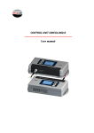
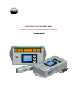
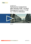
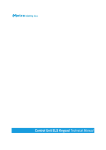
Reader Terminal Keypad Technical Manual Reader Terminal Keypad Technical Manual Table of contents Reader Terminal Combo User Manual .................................................................................................... 3 Product description ............................................................................................................................. 3 Connections ........................................................................................................................................ 4 Power and Metra NET Network connection ................................................................................... 4 DIP switch settings .............................................................................................................................. 6 Network address ............................................................................................................................. 7 Operating indicator ............................................................................................................................. 8 Maintenance ....................................................................................................................................... 8 Technical data ..................................................................................................................................... 9 Appendix ............................................................................................................................................. 9 Page 2 Reader Terminal Keypad Technical Manual Reader Terminal Keypad User Manual Manufacturer: Metra inženiring d.o.o. IOC Trzin Špruha 19 SI-1236 Trzin, Slovenia System: Product Group: Types: Year of Construction: Metra ELS NET– Electronic Locking Systems Reader Terminal Declaration of Conformity: phone: fax: web: +386 1 56 10 740 +386 1 56 10 744 www.metra.si RTKP 2011-2013 The Metra ELS NET products have been developed, designed and manufactured in accordance with the EU directive for Electromagnetic Compatibility (2004/108/EC). Reader Terminal Keypad User Manual [rev.0-140512] 2013 Metra inženiring d.o.o. All Rights reserved. No part of this manual may be reproduced in any form or by any means without prior written permission of Metra inženiring d.o.o. The contents of this manual are subject to change without notice. All efforts have been made to ensure the accuracy of the contents of this manual, however, should any errors be detected, Metra inženiring would greatly appreciate being informed of them. Metra inženiring d.o.o. can assume no responsibility for any errors in this manual. Product description Metra Reader Terminal Keypad is a user interface for Metra ELS NET systems. In combination with external reader (e.g. barcode scanner) its primary function is to read tickets as locker keys and show the locker number on a four digit LED display. Twelve key washable keypad is integrated to enable additional user interaction (PIN, locker number, etc.) and can be used for unlocking instead of ticket. Display Keypad also performs audio signalization and shows an alarm message if an attempt of break-in is detected on a Metra Electric Lock connected to a Metra Locker Controller. Master keys and codes are stored in its internal memory for emergency procedures. In these situations it works independent of the Metra ELS NET software. Page 3 Reader Terminal Keypad Technical Manual Connections # description 1 BDM Loader 2 External Reader/Barcode Scanner # description 3 Power and Metra NET Network Power and Metra NET Network connection WARNING Mind the power and Metra NET Network polarity! Wrong polarity could result in irreparable damage to the device. Respect power requirements data! Using unsuitable power supply could result in damage to the power supply and to the device. Regulated DC power supply is required for proper operation. Connect as many units as possible to a single power supply unit. See chapter “Technical data” for power requirements. The Metra NET Network connection provides for operational functionality of the Reader Terminal Combo. Tools required: Small flathead screwdriver Page 4 Reader Terminal Keypad Technical Manual NOTE Cable included with the Metra Reader Terminal Combo already has connector attached and therefore you can skip step 1. STEP 1: Insert wires from the 12V DC regulated power supply and Metra NET Network cable into the connector and fasten them with screws. STEP 2: Attach the connector to the Door Access Terminal’s main electronics board. Barcode scanner connection # 1 description # Reader IN 2 ISP Loader Page 5 description Reader Terminal Keypad Technical Manual STEP 1: Attach the external reader 6 pole flat cable from the Reader Terminal Keypad to the connector on Barcode Scanner electronics board. DIP switch settings # 1 description # DIP switch description 2 Parameters request button By changing the DIP Switch pins position, different network address can be set. To change between different pins positions, use a small flat headed screwdriver or similar object to push DIP switch pins to desired position. After each address change or after device’s first installation power off and back on the device (for the new settings to take effect) and obtain operating parameters. Operating parameters are obtained through the Metra NET Network. The server must be set up and running for that purpose. To obtain operating parameters, press the PARAMETERS REQUEST button. NOTE Network based functionality will be present only if the server is running and the Reader Terminal has been properly configured. Page 6 Reader Terminal Keypad Technical Manual Network address After installation is complete, the device network address must be set by DIP switches. NOTE Each Metra device must have different address setting. Switch #1 must be set to OFF (switch down). Look up the code for desired address in the coding table. Set switches #2 through #8 to indicated positions, where: 0 indicates the corresponding switch is in OFF position (switch down) 1 indicates the corresponding switch is in ON position (switch up) Coding table: 2 0 0 0 0 0 0 0 0 0 0 0 0 0 0 0 0 0 0 0 0 0 0 0 0 0 0 0 0 0 0 0 0 0 0 0 switch positions 3 4 5 6 7 0 0 0 0 0 0 0 0 0 0 0 0 0 0 1 0 0 0 0 1 0 0 0 1 0 0 0 0 1 0 0 0 0 1 1 0 0 0 1 1 0 0 1 0 0 0 0 1 0 0 0 0 1 0 1 0 0 1 0 1 0 0 1 1 0 0 0 1 1 0 0 0 1 1 1 0 0 1 1 1 0 1 0 0 0 0 1 0 0 0 0 1 0 0 1 0 1 0 0 1 0 1 0 1 0 0 1 0 1 0 0 1 0 1 1 0 1 0 1 1 0 1 1 0 0 0 1 1 0 0 0 1 1 0 1 0 1 1 0 1 0 1 1 1 0 0 1 1 1 0 0 1 1 1 1 0 1 1 1 1 1 0 0 0 0 1 0 0 0 0 1 0 0 0 1 8 0 1 0 1 0 1 0 1 0 1 0 1 0 1 0 1 0 1 0 1 0 1 0 1 0 1 0 1 0 1 0 1 0 1 0 address 100 101 102 103 104 105 106 107 108 109 110 111 112 113 114 115 116 117 118 119 120 121 122 123 124 125 126 127 128 129 130 131 132 133 134 Page 7 2 1 1 1 1 1 1 1 1 1 1 1 1 1 1 1 1 1 1 1 1 1 1 1 1 1 1 1 1 1 1 1 1 1 1 1 switch positions 3 4 5 6 7 0 0 0 0 0 0 0 0 0 0 0 0 0 0 1 0 0 0 0 1 0 0 0 1 0 0 0 0 1 0 0 0 0 1 1 0 0 0 1 1 0 0 1 0 0 0 0 1 0 0 0 0 1 0 1 0 0 1 0 1 0 0 1 1 0 0 0 1 1 0 0 0 1 1 1 0 0 1 1 1 0 1 0 0 0 0 1 0 0 0 0 1 0 0 1 0 1 0 0 1 0 1 0 1 0 0 1 0 1 0 0 1 0 1 1 0 1 0 1 1 0 1 1 0 0 0 1 1 0 0 0 1 1 0 1 0 1 1 0 1 0 1 1 1 0 0 1 1 1 0 0 1 1 1 1 0 1 1 1 1 1 0 0 0 0 1 0 0 0 0 1 0 0 0 1 8 0 1 0 1 0 1 0 1 0 1 0 1 0 1 0 1 0 1 0 1 0 1 0 1 0 1 0 1 0 1 0 1 0 1 0 address 164 165 166 167 168 169 170 171 172 173 174 175 176 177 178 179 180 181 182 183 184 185 186 187 188 189 190 191 192 193 194 195 196 197 198 Reader Terminal Keypad Technical Manual 0 0 0 0 0 0 0 0 0 0 0 0 0 0 0 0 0 0 0 0 0 0 0 0 0 0 0 0 0 1 1 1 1 1 1 1 1 1 1 1 1 1 1 1 1 1 1 1 1 1 1 1 1 1 1 1 1 1 0 0 0 0 0 0 0 0 0 0 0 0 0 1 1 1 1 1 1 1 1 1 1 1 1 1 1 1 1 0 0 0 0 0 1 1 1 1 1 1 1 1 0 0 0 0 0 0 0 0 1 1 1 1 1 1 1 1 0 1 1 1 1 0 0 0 0 1 1 1 1 0 0 0 0 1 1 1 1 0 0 0 0 1 1 1 1 1 0 0 1 1 0 0 1 1 0 0 1 1 0 0 1 1 0 0 1 1 0 0 1 1 0 0 1 1 1 0 1 0 1 0 1 0 1 0 1 0 1 0 1 0 1 0 1 0 1 0 1 0 1 0 1 0 1 135 136 137 138 139 140 141 142 143 144 145 146 147 148 149 150 151 152 153 154 155 156 157 158 159 160 161 162 163 1 1 1 1 1 1 1 1 1 1 1 1 1 1 1 1 1 1 1 1 1 1 1 1 1 1 1 1 1 1 1 1 1 1 1 1 1 1 1 1 1 1 1 1 1 1 1 1 1 1 1 1 1 1 1 1 1 1 0 0 0 0 0 0 0 0 0 0 0 0 0 1 1 1 1 1 1 1 1 1 1 1 1 1 1 1 1 0 0 0 0 0 1 1 1 1 1 1 1 1 0 0 0 0 0 0 0 0 1 1 1 1 1 1 1 1 0 1 1 1 1 0 0 0 0 1 1 1 1 0 0 0 0 1 1 1 1 0 0 0 0 1 1 1 1 1 0 0 1 1 0 0 1 1 0 0 1 1 0 0 1 1 0 0 1 1 0 0 1 1 0 0 1 1 1 0 1 0 1 0 1 0 1 0 1 0 1 0 1 0 1 0 1 0 1 0 1 0 1 0 1 0 1 199 200 201 202 203 204 205 206 207 208 209 210 211 212 213 214 215 216 217 218 219 220 221 222 223 224 225 226 227 Operating indicator When the unit is running, blue dot on the left side of the display panel is blinking. Maintenance No special maintenance is needed. Regular cleaning is recommended. The unit should be cleaned using soft cloth and dedicated cleaners for plastic surfaces e.g. car dashboard cleaning agents. Do not Page 8 Reader Terminal Keypad Technical Manual use any aggressive or abrasive agents or solvents as they might cause permanent damage to the device surface. Technical data Operating voltage Current consumption Operating temperature range Audio signal Visual signalization Connectors Dimensions in mm (w/h/l) 12V DC regulated (11.5 – 15V DC tolerated) 0.50 A -10 to +50 °C integrated piezoelectric beeper 4 digit LED display with decimal points. Power, Metra NET Network 214/79/83 Appendix 1 Physical dimensions Reader Terminal Keypad Reader Terminal Mounting hole 2 Physical dimensions Barcode Scanner Barcode Scanner Mounting hole 3 Inner connections schematic Page 9 Physical dimensions Appendix 1 Reader Terminal Keypad 233 213.4 98 78.6 1 2 3 4 5 6 7 8 9 0 80.5 Electronic Locking System 120 m ste ing ck 3 2 6 1 5 4 8 9 7 0 nic Lo tro c Ele Reader Terminal mounting hole 73 79 min 100 Oval hole must be provided for mounting the Reader Terminal unit. If not already CNC machined on locker assembly, a special dummy drill mask is available to facilitate the drilling procedure. min 300 214 4 208 Sy Physical dimensions Appendix 2 Barcode Scanner 72 78.6 110 Barcode Scanner mounting hole 73 79 min 120 Round hole must be provided for mounting the Barcode Scanner. min 100 79 4 73 Inner connections schematic Appendix 3 1 2 3 4 5 6 7 8 Schematic shows Barcode Scanner