1
supertirfor
™
E
42/C
/
6
0
20
Treuils à mâchoires motorisés hydrauliques TU16H et TU32H
Hydraulic powered Griphoists TU16H and TU32H
Gemotoriseerde, hydraulische lieren TU16H en TU32H
Motorbetriebene hydraulische Mehrzweck-Seilzüge TU16H und TU32H
Français
English
Dutch
Deutsch
FR
Instructions d’emploi et
d’entretien
Traduction de notice originale
NL
GB
Operation and maintenance
manual
Original manual
DE
Handleiding voor gebruik en
onderhoud
Vertaling van de oorspronkelijke
handleiding
Gebrauchs- und Wartungsanleitung
Übersetzung der Originalanleitung
1
SOMMAIRE
Page
Consignes prioritaires . . . . . . . . . . . . . . . . . . . . . . . . . . . . . . . . . . . . . . . . . . . . . . . . . . . . . . . . . . . . . . . . . . . . .4
Définition
. . . . . . . . . . . . . . . . . . . . . . . . . . . . . . . . . . . . . . . . . . . . . . . . . . . . . . . . . . . . . . . . . . . . . . . . . . . .5
1. Présentation . . . . . . . . . . . . . . . . . . . . . . . . . . . . . . . . . . . . . . . . . . . . . . . . . . . . . . . . . . . . . . . . . . . . . . . . . .5
1.1 Treuil à mâchoires SUPERTIRFOR™ . . . . . . . . . . . . . . . . . . . . . . . . . . . . . . . . . . . . . . . . . . . . . . . . .5
1.2 Groupe hydraulique . . . . . . . . . . . . . . . . . . . . . . . . . . . . . . . . . . . . . . . . . . . . . . . . . . . . . . . . . . . . . . .5
1.3 Composition d’une livraison standard . . . . . . . . . . . . . . . . . . . . . . . . . . . . . . . . . . . . . . . . . . . . . . . . .5
1.4 Réglementations et normes applicables . . . . . . . . . . . . . . . . . . . . . . . . . . . . . . . . . . . . . . . . . . . . . . .6
1.5 Accessoires compatibles . . . . . . . . . . . . . . . . . . . . . . . . . . . . . . . . . . . . . . . . . . . . . . . . . . . . . . . . . . .6
FR
2. Descriptions . . . . . . . . . . . . . . . . . . . . . . . . . . . . . . . . . . . . . . . . . . . . . . . . . . . . . . . . . . . . . . . . . . . . . . . . . .7
2.1 Spécifications . . . . . . . . . . . . . . . . . . . . . . . . . . . . . . . . . . . . . . . . . . . . . . . . . . . . . . . . . . . . . . . . . . . .7
2.1.1 Appareil SUPERTIRFOR™ . . . . . . . . . . . . . . . . . . . . . . . . . . . . . . . . . . . . . . . . . . . . . . . . . . . . .8
2.1.2 Groupes hydrauliques . . . . . . . . . . . . . . . . . . . . . . . . . . . . . . . . . . . . . . . . . . . . . . . . . . . . . . . . .8
2.1.3 Flexibles hydrauliques . . . . . . . . . . . . . . . . . . . . . . . . . . . . . . . . . . . . . . . . . . . . . . . . . . . . . . . . .9
2.1.4 Groupe hydraulique à moteur électrique . . . . . . . . . . . . . . . . . . . . . . . . . . . . . . . . . . . . . . . . . . .9
2.1.5 Groupe hydraulique à moteur thermique . . . . . . . . . . . . . . . . . . . . . . . . . . . . . . . . . . . . . . . . . .9
2.1.6 Pompe hydraulique . . . . . . . . . . . . . . . . . . . . . . . . . . . . . . . . . . . . . . . . . . . . . . . . . . . . . . . . . .10
2.1.7 Schéma électrique du groupe hydraulique à moteur électrique . . . . . . . . . . . . . . . . . . . . . . . .10
3. Schémas de montage . . . . . . . . . . . . . . . . . . . . . . . . . . . . . . . . . . . . . . . . . . . . . . . . . . . . . . . . . . . . . . . . . .10
4. Mise en service . . . . . . . . . . . . . . . . . . . . . . . . . . . . . . . . . . . . . . . . . . . . . . . . . . . . . . . . . . . . . . . . . . . . . . .11
4.1 Appareil SUPERTIRFOR™ . . . . . . . . . . . . . . . . . . . . . . . . . . . . . . . . . . . . . . . . . . . . . . . . . . . . . . . . . . . . .11
4.1.1 TU16H . . . . . . . . . . . . . . . . . . . . . . . . . . . . . . . . . . . . . . . . . . . . . . . . . . . . . . . . . . . . . . . . . . . .11
4.1.2 TU32H . . . . . . . . . . . . . . . . . . . . . . . . . . . . . . . . . . . . . . . . . . . . . . . . . . . . . . . . . . . . . . . . . . . .11
4.2 Câble SUPERTIRFOR™ . . . . . . . . . . . . . . . . . . . . . . . . . . . . . . . . . . . . . . . . . . . . . . . . . . . . . . . . . . .11
4.3 Groupe hydraulique . . . . . . . . . . . . . . . . . . . . . . . . . . . . . . . . . . . . . . . . . . . . . . . . . . . . . . . . . . . . . . .11
4.3.1 Version à moteur électrique . . . . . . . . . . . . . . . . . . . . . . . . . . . . . . . . . . . . . . . . . . . . . . . . . . . .12
4.3.1.1 Modification de la tension d’alimentation de 400 V en 230 V
(modification du câblage étoile en triangle) . . . . . . . . . . . . . . . . . . . . . . . . . . . . . . . . . . .12
4.3.1.2 Vérification du sens de rotation moteur . . . . . . . . . . . . . . . . . . . . . . . . . . . . . . . . . . . . . .12
4.3.1.3 Inversion du sens de rotation du moteur . . . . . . . . . . . . . . . . . . . . . . . . . . . . . . . . . . . . .12
4.3.2 Version à moteur thermique . . . . . . . . . . . . . . . . . . . . . . . . . . . . . . . . . . . . . . . . . . . . . . . . . . . .12
4.3.3 Flexibles . . . . . . . . . . . . . . . . . . . . . . . . . . . . . . . . . . . . . . . . . . . . . . . . . . . . . . . . . . . . . . . . . . .13
5. Débrayage et embrayage . . . . . . . . . . . . . . . . . . . . . . . . . . . . . . . . . . . . . . . . . . . . . . . . . . . . . . . . . . . . . . .13
5.1 TU16H . . . . . . . . . . . . . . . . . . . . . . . . . . . . . . . . . . . . . . . . . . . . . . . . . . . . . . . . . . . . . . . . . . . . . . . . .13
5.2 TU32H . . . . . . . . . . . . . . . . . . . . . . . . . . . . . . . . . . . . . . . . . . . . . . . . . . . . . . . . . . . . . . . . . . . . . . . . .13
6. Amarrage . . . . . . . . . . . . . . . . . . . . . . . . . . . . . . . . . . . . . . . . . . . . . . . . . . . . . . . . . . . . . . . . . . . . . . . . . . . .14
6.1 Vérifications préliminaires avant amarrage . . . . . . . . . . . . . . . . . . . . . . . . . . . . . . . . . . . . . . . . . . . . .14
6.2 Amarrage . . . . . . . . . . . . . . . . . . . . . . . . . . . . . . . . . . . . . . . . . . . . . . . . . . . . . . . . . . . . . . . . . . . . . . .14
6.2.1 Amarrage à la broche du TU32H . . . . . . . . . . . . . . . . . . . . . . . . . . . . . . . . . . . . . . . . . . . . . . . .14
6.2.2 Amarrage au crochet du TU16H . . . . . . . . . . . . . . . . . . . . . . . . . . . . . . . . . . . . . . . . . . . . . . . .14
6.2.3 Amarrage au crochet optionnel du TU32H . . . . . . . . . . . . . . . . . . . . . . . . . . . . . . . . . . . . . . . . .14
7. Manoeuvre . . . . . . . . . . . . . . . . . . . . . . . . . . . . . . . . . . . . . . . . . . . . . . . . . . . . . . . . . . . . . . . . . . . . . . . . . . .14
7.1 Vérifications avant manoeuvre . . . . . . . . . . . . . . . . . . . . . . . . . . . . . . . . . . . . . . . . . . . . . . . . . . . . . .14
7.2 Mettre en route le moteur du groupe hydraulique . . . . . . . . . . . . . . . . . . . . . . . . . . . . . . . . . . . . . . . .14
7.2.1 Cas du groupe à moteur électrique . . . . . . . . . . . . . . . . . . . . . . . . . . . . . . . . . . . . . . . . . . . . . .14
7.2.2 Cas du groupe à moteur thermique . . . . . . . . . . . . . . . . . . . . . . . . . . . . . . . . . . . . . . . . . . . . . .15
7.3 Régler la vitesse d’avance désirée . . . . . . . . . . . . . . . . . . . . . . . . . . . . . . . . . . . . . . . . . . . . . . . . . . .15
7.3.1 Modèle 1 voie . . . . . . . . . . . . . . . . . . . . . . . . . . . . . . . . . . . . . . . . . . . . . . . . . . . . . . . . . . . . . . .15
7.3.2 Modèle 2 voies . . . . . . . . . . . . . . . . . . . . . . . . . . . . . . . . . . . . . . . . . . . . . . . . . . . . . . . . . . . . . .15
7.3.3 Modèle 4 voies . . . . . . . . . . . . . . . . . . . . . . . . . . . . . . . . . . . . . . . . . . . . . . . . . . . . . . . . . . . . . .15
7.4 Utilisation en mode manuel . . . . . . . . . . . . . . . . . . . . . . . . . . . . . . . . . . . . . . . . . . . . . . . . . . . . . . . . .15
-2-
8. Mise hors service et stockage . . . . . . . . . . . . . . . . . . . . . . . . . . . . . . . . . . . . . . . . . . . . . . . . . . . . . . . . . . . .15
8.1 Mise hors service des groupes hydrauliques à moteur électrique . . . . . . . . . . . . . . . . . . . . . . . . . . .15
8.2 Mise hors service des groupes hydrauliques à moteur thermique . . . . . . . . . . . . . . . . . . . . . . . . . . .15
8.3 Mise hors service des appareils SUPERTIRFOR™ . . . . . . . . . . . . . . . . . . . . . . . . . . . . . . . . . . . . . .15
8.4 Stockage des groupes, appareils et câble . . . . . . . . . . . . . . . . . . . . . . . . . . . . . . . . . . . . . . . . . . . . .15
9. Dispositifs de sécurité . . . . . . . . . . . . . . . . . . . . . . . . . . . . . . . . . . . . . . . . . . . . . . . . . . . . . . . . . . . . . . . . . .16
9.1 Appareils SUPERTIRFOR™ TU16H et TU32H . . . . . . . . . . . . . . . . . . . . . . . . . . . . . . . . . . . . . . . . . .16
9.1.1 Dispositif de sécurité limitant les surcharges . . . . . . . . . . . . . . . . . . . . . . . . . . . . . . . . . . . . . . .16
9.1.1.1 Goupilles de sécurité SUPERTIRFOR™ . . . . . . . . . . . . . . . . . . . . . . . . . . . . . . . . . . . . .16
9.1.1.2 Vérins hydrauliques . . . . . . . . . . . . . . . . . . . . . . . . . . . . . . . . . . . . . . . . . . . . . . . . . . . . . .16
9.1.2 Sécurité de débrayage . . . . . . . . . . . . . . . . . . . . . . . . . . . . . . . . . . . . . . . . . . . . . . . . . . . . . . . .16
9.2 Groupes hydrauliques . . . . . . . . . . . . . . . . . . . . . . . . . . . . . . . . . . . . . . . . . . . . . . . . . . . . . . . . . . . . .16
9.2.1 Dispositif ‘’Homme mort’’ . . . . . . . . . . . . . . . . . . . . . . . . . . . . . . . . . . . . . . . . . . . . . . . . . . . . . .16
9.2.2 Soupape de sécurité . . . . . . . . . . . . . . . . . . . . . . . . . . . . . . . . . . . . . . . . . . . . . . . . . . . . . . . . .16
9.2.3 Sonde thermique de protection . . . . . . . . . . . . . . . . . . . . . . . . . . . . . . . . . . . . . . . . . . . . . . . . .16
10. Remplacement des goupilles de sécurité SUPERTIRFOR™ . . . . . . . . . . . . . . . . . . . . . . . . . . . . . . . . . . .16
10.1 Précautions d’usages . . . . . . . . . . . . . . . . . . . . . . . . . . . . . . . . . . . . . . . . . . . . . . . . . . . . . . . . . . . .16
10.2 Matériel nécessaire . . . . . . . . . . . . . . . . . . . . . . . . . . . . . . . . . . . . . . . . . . . . . . . . . . . . . . . . . . . . . .16
10.3 TU16H . . . . . . . . . . . . . . . . . . . . . . . . . . . . . . . . . . . . . . . . . . . . . . . . . . . . . . . . . . . . . . . . . . . . . . . .16
10.4 TU32H . . . . . . . . . . . . . . . . . . . . . . . . . . . . . . . . . . . . . . . . . . . . . . . . . . . . . . . . . . . . . . . . . . . . . . . .17
11. Câble SUPERTIRFOR™ . . . . . . . . . . . . . . . . . . . . . . . . . . . . . . . . . . . . . . . . . . . . . . . . . . . . . . . . . . . . . . .17
12. Entretien des appareils . . . . . . . . . . . . . . . . . . . . . . . . . . . . . . . . . . . . . . . . . . . . . . . . . . . . . . . . . . . . . . . .17
12.1 Appareils SUPERTIRFOR™ TU16H et TU32H . . . . . . . . . . . . . . . . . . . . . . . . . . . . . . . . . . . . . . . . .17
12.2 Groupe hydraulique et flexibles . . . . . . . . . . . . . . . . . . . . . . . . . . . . . . . . . . . . . . . . . . . . . . . . . . . . .17
12.3 Moteur thermique . . . . . . . . . . . . . . . . . . . . . . . . . . . . . . . . . . . . . . . . . . . . . . . . . . . . . . . . . . . . . . .18
13. Utilisations fautives interdites . . . . . . . . . . . . . . . . . . . . . . . . . . . . . . . . . . . . . . . . . . . . . . . . . . . . . . . . . . .18
14. Anomalies de fonctionnement . . . . . . . . . . . . . . . . . . . . . . . . . . . . . . . . . . . . . . . . . . . . . . . . . . . . . . . . . . .19
15. Vérifications réglementaires . . . . . . . . . . . . . . . . . . . . . . . . . . . . . . . . . . . . . . . . . . . . . . . . . . . . . . . . . . . .20
16. Marquages et plaques d’appareils . . . . . . . . . . . . . . . . . . . . . . . . . . . . . . . . . . . . . . . . . . . . . . . . . . . . . . . .20
16.1 Plaque des caractéristiques du groupe hydraulique . . . . . . . . . . . . . . . . . . . . . . . . . . . . . . . . . . . . . . . . .20
16.2 Etiquettes d’instructions d’utilisation des appareils SUPERTIRFOR™TU16H et TU32H . . . . . . . . .
avec les caractéristiques du câble SUPERTIRFOR™TRACTEL® à utiliser . . . . . . . . . . . . . . . . . . .20
16.3 Etiquette mentionnant les interdictions d’être situé sous la charge,d’utiliser l’appareil . . . . . . . . . . .
en levage de personne et l’obligation de lire la notice d’instructions d’emploi et d’entretien . . . . . .20
16.4 Etiquette mentionnant la puissance acoustique garantie de chacun des appareils . . . . . . . . . . . . .20
16.5 Plaque des caractéristiques du thermostat installé sur le moteur électrique . . . . . . . . . . . . . . . . . .20
16.6 Plaques des caractéristiques du moteur électrique . . . . . . . . . . . . . . . . . . . . . . . . . . . . . . . . . . . . .21
16.7 Etiquette d’information du moteur thermique . . . . . . . . . . . . . . . . . . . . . . . . . . . . . . . . . . . . . . . . . .22
Fiche d’inspection et de maintenance . . . . . . . . . . . . . . . . . . . . . . . . . . . . . . . . . . . . . . . . . . . . . . . . . . . . . . . .23
ILLUSTRATIONS . . . . . . . . . . . . . . . . . . . . . . . . . . . . . . . . . . . . . . . . . . . . . . . . . . . . . . . . . . . . . . . . . . .A-B-C
-3-
FR
CONSIGNES PRIORITAIRES
FR
15.
1. Avant d’installer et d’utiliser cet équipement, il est
indispensable, pour sa sécurité d’emploi et son
efficacité, de prendre connaissance de la présente
notice et de se conformer à ses prescriptions. Un
exemplaire de cette notice doit être conservé à
disposition de tout opérateur. Des exemplaires
supplémentaires peuvent être fournis sur demande.
2. Ne pas utiliser cet équipement si l’une des plaques
fixées sur l’équipement, ou si l’un des marquages y
figurant, comme indiqué à la fin de la présente notice,
n’est plus présent ou lisible. En cas de marquage par
plaque, des plaques identiques peuvent être fournies sur
demande qui doivent être fixées avant de continuer
l’utilisation de l’équipement.
3. Assurez-vous que toute personne à qui vous confiez
l’utilisation de cet équipement en connaît le maniement
et est apte à assumer les exigences de sécurité que ce
maniement exige pour l’emploi concerné. La présente
notice doit être mise à sa disposition.
4. La mise en oeuvre de cet équipement doit être conforme
à la réglementation et aux normes de sécurité
applicables concernant l’installation, l’utilisation, la
maintenance et le contrôle des équipements de levage
de matériel.
5. Pour tout usage professionnel, cet équipement, doit être
placé sous la responsabilité d’une personne connaissant
la réglementation applicable, et ayant autorité pour en
assurer l’application si elle n’en est pas l’opérateur.
6. Toute personne utilisant cet équipement pour la
première fois doit vérifier, hors risque, avant d’y
appliquer la charge, et sur une faible hauteur de levage,
qu’elle en a compris toutes les conditions de sécurité et
d’efficacité de son maniement.
7. La mise en place et la mise en fonctionnement de cet
équipement doivent être effectuées dans des conditions
assurant la sécurité de l’opérateur conformément à la
réglementation applicable à sa catégorie.
8. Avant chaque utilisation de l’équipement, vérifier qu’il est
en bon état apparent, ainsi que les accessoires utilisés
avec l’équipement.
9. TRACTEL® exclut sa responsabilité pour le fonctionnement de cet équipement dans une configuration de
montage non décrite dans la présente notice.
10. Toute modification de l’équipement hors du contrôle de
TRACTEL®, ou suppression de pièce en faisant partie
exonèrent TRACTEL® de sa responsabilité.
11. TRACTEL® ne garantit le fonctionnement de l’équipement que s’il est équipé d’un câble SUPERTIRFOR™
TRACTEL® d’origine, suivant les spécifications indiquées dans le présent manuel.
12. Toute opération de montage ou de démontage de cet
équipement non décrite dans cette notice, ou toute
réparation effectuée hors du contrôle de TRACTEL®
exonèrent TRACTEL® de sa responsabilité, spécialement en cas de remplacement de pièces d’origine par
des pièces d’une autre provenance.
13. Toute intervention sur le câble SUPERTIRFOR™ pour
le modifier ou le réparer en dehors du contrôle de
TRACTEL® exclut la responsabilité de TRACTEL® pour
les suites de cette intervention.
14. Cet équipement ne doit jamais être utilisé pour des
opérations autres que celles décrites dans cette notice.
Il ne doit jamais être utilisé pour une charge supérieure
à la charge maximale d’utilisation indiquée sur
16.
17.
18.
19.
20.
21.
22.
23.
24.
25.
l’équipement. Il ne doit jamais être utilisé en
atmosphère explosive.
Il est interdit d’utiliser cet équipement pour le levage ou
le déplacement de personnes.
Lorsqu’une charge doit être soulevée par plusieurs
appareils, l’installation de ceux-ci doit être précédée
d’une étude technique par un technicien compétent,
puis conduite conformément à cette étude, notamment
pour assurer la répartition constante de la charge dans
des conditions convenables. TRACTEL® exclut toute
responsabilité pour le cas où l’appareil TRACTEL®
serait utilisé en combinaison avec d’autres appareils de
levage d’autre origine.
Cet appareil doit être amarré à un point fixe et à une
structure suffisamment résistants, compte tenu du
coefficient de sécurité applicable, pour supporter la
charge maximale d’utilisation indiquée sur la présente
notice. En cas d’utilisation de plusieurs appareils, la
résistance de la structure et du point d’amarrage doit
être fonction du nombre d’appareil suivant leur charge
maximale d’utilisation.
Pendant les opérations de levage, en montée et en
descente, l’opérateur doit rester constamment en vue
de la charge.
Le contrôle permanent du bon état apparent de
l’équipement et son bon entretien font partie des
mesures nécessaires à sa sécurité d’emploi. Suivant la
nature de l’environnement, surveiller l’absence de
corrosion.
Ne jamais stationner ou circuler sous la charge.
Signaliser et interdire l’accès à la zone située sous la
charge.
Le bon état du câble SUPERTIRFOR™ est une
condition essentielle de sécurité et de bon
fonctionnement de l’appareil. Le contrôle du bon état
du câble SUPERTIRFOR™ doit être effectué à chaque
utilisation comme indiqué au chapitre « câble ». Tout
câble SUPERTIRFOR™ présentant des signes de
détérioration doit être immédiatement mis au rebut
définitivement.
Quand l’équipement n’est pas utilisé, il doit être placé
hors d’atteinte de personnes non autorisées à l’utiliser.
L’équipement doit être vérifié périodiquement par un
réparateur agréé TRACTEL® comme indiqué dans
cette notice.
L’opérateur doit s’assurer en cours d’utilisation que le
câble SUPERTIRFOR™ est constamment tendu par
la charge, et particulièrement que celle-ci n’est pas
neutralisée temporairement par un obstacle en
descente, ce qui peut entraîner un risque de rupture du
câble SUPERTIRFOR™ lorsque la charge se libère de
son obstacle.
En cas d’arrêt définitif d’utilisation, mettre l’équipement
au rebut dans des conditions interdisant son utilisation.
Respecter la réglementation sur la protection de
l’environnement.
IMPORTANT : Pour tout usage professionnel,
spécialement si vous devez confier cet appareil à un
personnel salarié ou assimilé, conformez vous à la
réglementation du travail applicable au montage, à la
maintenance et à l’utilisation de ce matériel, notamment
concernant les vérifications exigées : vérification à la
première mise en service par l’utilisateur, vérifications
périodiques et après démontage ou réparation.
-4-
1.1 Treuil à mâchoires SUPERTIRFOR™
Définition
Dans ce manuel, les termes suivants signifient :
« Utilisateur » : Personne ou service responsable de la
gestion et de la sécurité d’utilisation du produit décrit dans
le manuel.
« Opérateur » : Personne ou service en charge :
1. De l’assemblage des éléments du produit reçu,
2. De son installation pour que le produit soit prêt à
l’utilisation,
3. De l’utilisation du produit pour lequel celui-ci est
destiné,
4. Du démontage,
5. De la désinstallation,
6. Ainsi que de son transport en vue du stockage et de
son rangement.
« Technicien » : Personne qualifiée, en charge des
opérations de maintenance décrites et permises à
l’utilisateur par le manuel, qui est compétent et familier
avec le produit.
« Service après-vente » : Société ou département autorisé
par une société du groupe TRACTEL® pour le service
après-vente ou les opérations de réparations du produit.
Contacter TRACTEL®.
« Appareil » : Treuil TIRFOR® et ses accessoires
« Equipement » : Ensemble composé de l’appareil, du
groupe hydraulique et de leurs accessoires.
« DANGER » : Pour les commentaires destinés à
éviter des dommages aux personnes (opérateurs ou tiers),
notamment des blessures, qu’elles soient mortelles, graves
ou légères. Ce pictogramme est constitué par un point
d’exclamation dans un triangle. »
« IMPORTANT » : Pour les commentaires destinés
à éviter une défaillance, ou un dommage matériel du
produit ou de l’équipement ou de l’environnement, mais ne
mettant pas directement en danger la vie ou la santé de
l’opérateur ni d’autres personnes.
« NOTE » : Pour commentaires concernant
les précautions nécessaires à suivre pour assurer une
installation, utilisation et maintenance efficaces et
commodes, sans implication de dommage.
1. Présentation
L’appareil SUPERTIRFOR™ est un appareil portatif de
traction et de levage qui assure toutes les fonctions du
treuil à mâchoires TIRFOR®. Il est muni d’un organe
d’amarrage (crochet ou broche suivant le modèle)
permettant de le fixer rapidement à tout point fixe
suffisamment résistant.
Il comporte, comme le treuil manuel :
- un levier de marche avant
- un levier de marche arrière
- un levier de débrayage
L’effort fourni par le groupe est transmis à l’un des leviers
de marche avant ou de marche arrière par le vérin.
L’appareil SUPERTIRFOR™ peut être également actionné
manuellement par son manche télescopique livré avec
l’appareil.
1.2 Groupe hydraulique
Le groupe hydraulique alimentant l’appareil est fourni dans
les deux versions suivantes :
- Groupe avec moteur électrique
- Groupe avec moteur thermique
Chacune de ces deux versions comporte un bloc de
distribution dans l’une des variantes suivantes :
- Une voie (un appareil)
- Deux voies (deux appareils ou un appareil)
- Quatre voies (quatre appareils)
Chaque voie comporte une prise de sortie HP (haute
pression) et une prise de retour BP (basse pression).
Chaque prise est reliée à l’appareil par un conduit flexible.
Le modèle « une voie » comporte une prise HP débitant
13 litres/min (identifiée « TU32H ») et une prise HP
débitant 8 litres / min, (identifiée « TU 16H »).
Le modèle « deux voies » comporte trois prises HP dont :
- deux prises débitent chacune 6,5 litres/min pouvant
alimenter les deux modèles de SUPERTIRFOR™,
- une prise débitant 13 litres / min. Cette prise est identifiée
« TU32H » (voir figure 30, page C) et est strictement
réservée à l’utilisation du TU32H.
Le modèle « quatre voies » comporte quatre prises HP
débitant chacune 3,25 litres/min pouvant alimenter les
deux modèles de SUPERTIRFOR™.
Chaque couple de prises HP et BP est relié au vérin de
l’appareil par deux flexibles.
L’équipement SUPERTIRFOR™ comprend :
- Un treuil à mâchoires motorisable TIRFOR® sur lequel est
monté un vérin hydraulique auto inverseur, au moyen d’un
ensemble « ferrure / sabot ». Nous le nommerons dans la
suite du document « appareil SUPERTIRFOR™ »
- Un groupe hydraulique (modèle SUPERTIRFOR™) de
motorisation alimentant ce vérin au moyen de conduits
flexibles.
1.3 Composition d’une livraison standard
Une livraison standard (TU16H ou TU32H) se compose
de :
- un groupe hydraulique avec moteur électrique ou
thermique (modèle SUPERTIRFOR™)
- des flexibles (une paire par voie et par appareil) équipés
de coupleurs rapides.
- un appareil SUPERTIRFOR™
- une ferrure de fixation boulonnée sur l’appareil
-5-
FR
FR
- un « sabot » fixé (TU32H) ou à fixer (TU16H) sur la
ferrure
- un câble métallique spécial « SUPERTIRFOR™ » équipé
d’un crochet, en longueur standard de 20 mètres, monté
sur touret
- un vérin hydraulique auto-inverseur SUPERTIRFOR™
(VA2 pour TU 16H ou VA3 pour TU 32H)
- un bidon de 20 L d’huile hydraulique spéciale pour pompe
hydraulique
- un manche télescopique
- la présente notice
- un certificat de conformité
- la notice du fournisseur du moteur thermique (groupe
avec moteur thermique)
- la notice de l’appareil TIRFOR® pour le fonctionnement
manuel
- 2 jeux de goupilles de sécurité SUPERTIRFOR™ de
rechange par appareil (TU16H : 6 goupilles de sécurité
SUPERTIRFOR™, TU32H : 2 goupilles de sécurité
SUPERTIRFOR™).
Afin d’assurer l’amélioration constante de ses produits,
TRACTEL® se réserve d’apporter, à tout moment, toute
modification jugée utile, aux matériels décrits dans la
présente notice.
Les sociétés du groupe TRACTEL® et leurs revendeurs
agréés vous fourniront sur demande la documentation
concernant la gamme des autres produits TRACTEL® :
Appareils de levage et de traction et leurs accessoires,
matériels d’accès de chantier et de façade, dispositifs de
sécurité pour charges, indicateurs de charge électroniques,
etc.
Le réseau TRACTEL® peut vous fournir un service d’après
vente et d’entretien périodique.
NOTE : le groupe hydraulique comporte des
bouchons amovibles à chaque sortie, qu’il convient de
conserver.
Pour une longueur de câble SUPERTIRFOR™ supérieure
à 80 m, consulter TRACTEL® .
1.4 Réglementation et normes applicables
L’équipement TU16H ou TU 32H est conforme à la
Directive « Machines » N° 98 / 37 / CEE (appareils de
levage de matériel) et à la Directive 2000 / 14 / CE relative
aux émissions sonores dans l’environnement des matériels
destinés à être utilisés à l’extérieur des bâtiments.
1.5 Accessoires compatibles
TRACTEL® peut fournir en option un crochet se fixant sur
la broche d’amarrage du TU 32H référence TRACTEL®
21877.
-6-
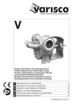
2. Description
2.1 Spécifications
SPECIFICATIONS
Groupe thermique / Groupe électrique
Groupe thermique
1 : Manomètre
2 : Bloc de commande
3 : Cadre de protection et de portage
4 : Régulateur de débit
5 : Bouchon fileté obturant l'orifice
de remplissage du réservoir
6 : Jauge d'huile (moteur thermique)
7 : Lanceur (moteur thermique)
8 : Moteur (électrique ou thermique)
9 : Indicateur de niveaux d'huile
10 : Réservoir d'huile hydraulique
Groupe électrique
11 : Coffret électrique
(moteur électrique)
12 : Bouchon de vidange
du réservoir
13 : Commande d'accélération
(moteur thermique)
14 : Boîtier de commande
(moteur électrique)
16
15 : Prise électrique
(moteur électrique)
16 : Plaque d'instruction
16a
2
24
26
P1 P2
TU16H équipé du vérin
29
31
TU32H équipé du vérin
16a : Levier de débrayage en
16b
position DEBRAYÉE (en traits pointillés)
23
16b : Levier de débrayage en
position EMBRAYÉE (en traits continus)
17 : Linguet
17
18 : Entrée de câble
25
19/20 : Plaques d'instructions (sur les 2 côtés de l'appareil)
28
21
27
21 : Goupilles de sécurité (TU16H = 3, TU32H = 1)
22
19/20 18
22 : Goupilles de sécurité de rechange
SUPERTIRFOR™ TU16H
23 : levier de marche avant
3
23
30 24 16a
22
16b 26
P2
24 : Levier de marche arrière
P1
25 : Sortie de câble
26 : Vérin auto-inverseur
P1 : Position du vérin en "marche avant"
21
25
P2 : Position du vérin en "marche arrière"
29
(position noircie)
27 : Ferrure
28 : Loquet de débrayage/embrayage
27
18
28
19/20
SUPERTIRFOR™ TU32H
-7-
29 : Support de vérin
30 : Bielle de commande
31 : Chape
FR
2.1.1 Appareils SUPERTIRFOR
MODELE
TU16H
TU32H
t
Mpa
1,6
10
3,2
9
kg
kg
kg
28
2,4
13
54,1
2,4
25
mm
mm
mm
mm
cm
788
360
185
68/119
1070
1290
430
204
68/119
mm
daN
kg
11,5
9600
0,54
5 x 26
16,3
19200
1,06
5 x 31
mm
mm
mm
mm
45
37
42
44
32,5
14
35
25
Niveau**** de pression acoustique continu équivalent pondéré A, LAeq (en dBA)
à 1m de l’appreil
68
80
Niveau**** de puissance acoustique garanti LwA (en dBA)
86
93
Charge maximale d’utilisation
Pression nominale* charge maxi 1 voie
Poids
Appareil
Levier télescopique
Câble standard 20 m équipé
FR
Dimensions de l’appareil
Longueur
Longueur avec crochet en option
Hauteur
Epaisseur
Levier : rentré / déployé
Câble original SUPERTIRFOR™
Diamètre
Charge de rupture garantie**
Poids au mètre
Type
Avance du câble*** SUPERTIRFOR™
Marche AV. à vide
Marche AV. CMU
Marche AR. à vide
Marche AR. CMU
* Cette valeur peut varier d’un appareil à l’autre, et peut également varier en 2 voies ou 4 voies
** Y compris les terminaisons du câble SUPERTIRFOR™
*** Avance du câble SUPERTIRFOR™ par course complète aller et retour du levier
**** Mesure effectuée à vide, au débit maximum, en marche AV. et marche AR.
2.1.2 Groupes hydrauliques
Nombre de vérins à alimenter
1
2
4
Bloc de commande
BC S
BC 2d
BC 4d
Nombre de flexibles
2
4/2**
8
Débit par vérin
L/min
8
13*
6,5
13*
3,25
Vitesse du câble SUPERTIRFOR™ à charge
nominale
Marche AV. CMU TU16H
Marche AR. CMU TU16H
Marche AV. CMU TU32H
Marche AR. CMU TU32H
m/min
m/min
m/min
m/min
2
2,3
0,7**
1,6**
1,5
2
0,35/0,7**
0,8/1,6**
0,75
1
0,17
0,4
* NE JAMAIS CONNECTER UN TU16H A LA SORTIE DE <<13 L/min>>
** Connectée sur sortie <<13 L/min>> (uniquement pour l’appareil TU32H)
-8-
2.1.3 Flexibles hydrauliques
Diamètre nominal
mm
10
Diamètre extérieur
mm
17,4
Pression de service max.
MPa
18
Pression de rupture min.
MPa
72
Référence PARKER
421SN-6
2.1.4 Groupe hydraulique à moteur électrique
FR
Dimensions l x L x H
Poids (sans huile)
mm
460 x 550 x 580
kg
46,5 (1 voie) / 47,2 (2 voies) / 48,2 (4 voies)
Type de moteur
Triphasé
Puissance
kW
Tension d’alimentation et courant à pleine charge
3
Δ 230V – 11,9A / Y 400V – 6,86A
Degré de protection du moteur électrique
IP55
Degré de protection de la prise de courant
IP44
Fréquence
Vitesse de rotation à pleine charge
Hz
50
tr/min
2830
Pôles
2
Niveau* de pression acoustique continu équivalent pondéré A,
LAeq (en dBA) à 1 m de l’appareil
69
Niveau* de puissance acoustique garanti LwA (en dBA)
87
* : mesure de l’appareil seul, débit nul
2.1.5 Groupe hydraulique à moteur thermique
Dimensions l x L x H
mm
Poids (sans huile groupe, sans essence)
kg
460 x 550 x 550
43,5 (1 voie) / 44,1 (2 voies) / 45,1 (4 voies)
Type de moteur
Refroidissement par air
Couple maxi.
10,77 N.m à 2400 tr/min
Cylindrée
mm3
Carburant
190
Essence sans plomb (indice d’octane ≥ 85)
Capacité du réservoir
L
0,8
Niveau* de pression acoustique continu équivalent pondéré A, LAeq
(en dBA)
81
Niveau* de puissance acoustique garanti LwA (en dBA)
97
Voir également les instructions d’utilisation et de maintenance du moteur.
Le réservoir à carburant du moteur est livré vide d’essence et le carter moteur contient de l’huile moteur.
* : mesure de l’appareil seul, débit nul, manette des gaz au maximum
-9-
2.1.6 Pompe hydraulique
Type
Pression maximum
A engrenages
Mpa
Débit
13 L /min
Sens de rotation
Horaire
Vitesse de rotation maximum
3000 tr/min
Huile hydraulique *
FR
25
TOTAL AZOLLA ZS32
* : fiche technique et fiche de donnée de sécurité disponibles sur demande. A la livraison, le carter du groupe (page 7,
figure 1, repère 10) est livré vide d’huile.
2.1.7 Schéma électrique du groupe hydraulique avec moteur électrique
appropriée entre le point d’amarrage et l’appareil (page A,
figure 7).
3. SCHEMAS DE MONTAGE
L’appareil SUPERTIRFOR™ est amarré à un point fixe, le
câble SUPERTIRFOR™ se déplaçant à travers l’appareil
(page A, figures 4 – 5 – 6).
DANGER : Tout montage, pour lequel il est
nécessaire de calculer les forces appliquées et de vérifier
la résistance des points fixes utilisés, doit être contrôlé par
un technicien qualifié et familier avec ce type de matériel.
DANGER : Dans des travaux tels que le guidage
d’une chute d’arbre, l’opérateur doit se mettre à l’écart de
la zone dangereuse en faisant passer le câble
SUPERTIRFOR™ dans une ou plusieurs poulies de
renvoi.
NOTE : Quel que soit le schéma de montage,
et si l’appareil SUPERTIRFOR™ est amarré directement à
un point fixe, il doit pouvoir s’aligner sans contrainte par
rapport à la direction de la charge ou de l’effort. A cette fin,
il est recommandé d’interposer une élingue de résistance
NOTE : Quel que soit le schéma de montage
utilisé, il faut toujours veiller à laisser les flexibles
d’alimentation et de retour d’huile libres de leur mouvement
et ne pas les contraindre par des angles brusques
notamment.
La capacité de l’appareil SUPERTIRFOR™ peut être
augmentée par l’emploi de poulies de mouflage (voir
exemples de schémas page A, figures 10 et 11).
L’augmentation de capacité indiquée est réduite suivant le
rendement des poulies.
Le diamètre de fond de gorge, des poulies utilisées, doit
être au moins égal à 16 fois le diamètre du câble
SUPERTIRFOR™. (Vérifier la réglementation applicable le
cas échéant).
- 10 -
4. MISE EN SERVICE
En marche avant, la bielle de commande (repère 30,
figure 21, page B) doit être connectée en position A avec le
levier de marche avant (repère 23, figure 21, page B).
4.1 APPAREIL SUPERTIRFOR™
4.1.1 TU16H
1) Monter le support de vérin (repère 29, figure 14, page B)
sur la ferrure repère 27 de l’appareil. Pour effectuer cette
opération, munissez-vous d’une clé à tube de 13 mm et
procéder comme suit :
• Dévisser les 6 vis et rondelles repère 1, le boulon avec
rondelle repère 2.
• Desserrer légèrement les 4 vis repère 3 d’un même côté
de l’appareil.
• Monter le support de vérin repère 29 en le positionnant
dans les pions de centrage (figure 15, repère 1, page B).
• Revisser les 6 vis et rondelles repère 1, mettre en place
le boulon avec rondelle repère 2.
• Bloquer toutes les vis repères 1, 2 et 3.
DANGER :
Ne
pas
utiliser
l’appareil
SUPERTIRFOR™ en présence d’un corps étranger à
l’intérieur de l’appareil.
IMPORTANT : Pendant le dévissage des vis repère
1 et leur remise en place, veiller à ne pas laisser tomber de
rondelle dans le carter du TU16H. En cas de chute d’une
rondelle, il faut impérativement la récupérer.
2) Repérer le sens de marche désiré. Fixer le vérin VA2
sur le support de vérin (page B, figure 16, repère 29),
par l’intermédiaire de la broche, à la place correspondant au sens de marche :
- MARCHE AVANT : vérin en position A
- MARCHE ARRIERE : vérin en position C
3) Fixer la chape du vérin page B, figure 16, repère 31 sur
le levier de marche avant ou de marche arrière par la
broche.
- MARCHE AVANT : chape de vérin en position B
- MARCHE ARRIERE : chape de vérin en position D
IMPORTANT : Il est interdit de monter deux vérins
simultanément sur un appareil SUPERTIRFOR™ TU16H.
NOTE : L’introduction de la broche pourra être
facilitée en manœuvrant le levier de marche pour lequel
l’utilisation est envisagée. Vérifier que les broches sont
correctement introduites dans leur logement. Un
claquement (correspondant au choc de la butée de la
broche contre le palier) permet de s’assurer que leur
verrouillage est correct (bien graisser les broches).
UTILISER UNIQUEMENT LA BROCHE D’ORIGINE
TRACTEL®.
4.1.2 TU32H
• Fixer le vérin VA3 sur le TU32H équipé de sa ferrure en
introduisant la broche du côté de l’entrée de câble
SUPERTIRFOR™ dans le SUPERTIRFOR™,
• Fixer la bielle de commande repère 30, figure 3, page 7,
bavette de caoutchouc dirigée vers le bas, au levier de
marche avant ou de marche arrière avec la broche. Les
broches sont équipées de goupille anneau-ressort.
Vérifier leur verrouillage correct.
En marche arrière, la bielle de commande (repère 30,
figure 21, page B) doit être connectée en position B avec le
levier de marche arrière (repère 24, figure 21, page B).
Aucun autre montage n’est autorisé. Quand un levier
de marche est actionné, l’autre doit rester libre.
UTILISER UNIQUEMENT LA BROCHE D’ORIGINE
TRACTEL®.
4.2 Câble SUPERTIRFOR™
DANGER : Il est recommandé de protéger les
mains par des gants de travail pour manipuler le câble
SUPERTIRFOR™.
IMPORTANT : Les câbles pour appareil
SUPERTIRFOR™ sont spécialement conçus pour être
utilisés avec les appareils SUPERTIRFOR™ conformément à la conception particulière de ces appareils.
TRACTEL® ne peut garantir la sécurité de fonctionnement
de ceux-ci avec des câbles autres que des câbles
SUPERTIRFOR™. Le câble SUPERTIRFOR™ doit être
lubrifié.
1. Dérouler le câble SUPERTIRFOR™ en évitant de le
tordre ou de former des boucles. (voir figure 44, page C)
2. Débrayer le mécanisme de l’appareil (voir chapitre 5
“Débrayage et Embrayage”)
3. Introduire le câble SUPERTIRFOR™ par l’orifice de
l’appareil situé à l’extrémité opposée à celle de l’organe
d’amarrage (crochet ou broche).
4. Pousser le câble à travers l’appareil en aidant le
mouvement au besoin par la manœuvre du levier de
marche avant.
5. Lorsque le câble SUPERTIRFOR™ est sorti du côté de
l’organe d’amarrage, le faire défiler en le tirant à la main
jusqu’au point souhaité.
6. Embrayer le mécanisme en manœuvrant la poignée de
débrayage (voir chapitre “Débrayage / Embrayage”)
7. Amarrer l’appareil SUPERTIRFOR™ ou le câble au
point fixe choisi (voir chapitre 6 “Amarrage”) en prenant
soin de verrouiller l’organe d’amarrage, crochet ou
broche, suivant le modèle.
4.3 Groupe hydraulique
Avant chaque mise en service, faire fonctionner le groupe
hydraulique, de manière à liquéfier l’huile hydraulique
contenue dans ledit groupe.
NOTE : Les opérations qui suivent sont des
manipulations à faire de préférence en atelier avant la mise
en service sur le chantier.
Le groupe hydraulique doit être posé horizontalement sur
un endroit stable et sur ses 4 pieds.
NOTE : Le réservoir repère 10, figure 1, page 7
des groupes hydrauliques est livré sans huile pour des
raisons de sécurité durant le transport.
- 11 -
FR
1) Faire le plein d’huile hydraulique. Pour cela, dévisser le
bouchon de remplissage (repère 5, figure 1, page 7).
Remplir le réservoir jusqu’à ce que le niveau atteigne le
voyant supérieur repère 9, figure 1, page 7.
IMPORTANT : Cette manœuvre de remplissage doit
être effectuée avec le maximum de soin afin d’éviter
l’introduction de poussières ou de corps étrangers dans le
réservoir. Elle doit si possible être effectuée à l’atelier ou au
dépôt avant le mise en service sur le chantier.
FR
2) Bien revisser le bouchon
3) Raccorder les flexibles au groupe. Les flexibles repérés
par une empreinte à leur extrémité et au niveau de
l’écrou tournant doivent être vissés sur les raccords
repérés par la même empreinte sur le bloc.
IMPORTANT : Sur un bloc de commande une voie,
il faut connecter le raccord de flexible du TU32H ou TU16H
au raccord de sortie du bloc identifié respectivement
TU32H ou TU16H (voir figure 29, page C).
IMPORTANT : Le bloc deux voies, peut être utilisé
comme bloc hydraulique une voie, en reliant le flexible à la
sortie << 13 L/min>> (repère S figure 30, page C). Ce cas
d’utilisation est strictement réservé à l’utilisation du TU32H.
NE JAMAIS CONNECTER UN TU16H A LA SORTIE
IDENTIFIEE TU32H.
IMPORTANT : Il est interdit de connecter plus de
quatre vérins sur un groupe hydraulique.
4.3.1 Version à moteur électrique
Toute intervention sur le matériel électrique doit être
effectuée par une personne qualifiée et familière avec ce
type de matériel.
Vérifier la tension d’alimentation disponible, 400 V ou 230
V, triphasé, 50Hz, selon le type de câblage envisagé. Les
moteurs des groupes hydrauliques sont câblés en usine
pour une utilisation sous une tension de 400 V (câblage en
étoile).
Il est possible de faire fonctionner les groupes hydrauliques
avec une tension de 230 V (câblage en triangle).
4.3.1.1 Modification de la tension d’alimentation de 400 V en 230 V (modification du
câblage étoile en triangle)
Pour faire le changement de tension de 400 V en 230 V,
procéder comme suit :
1) Vérifier que l’appareil n’est pas connecté à une source
d’énergie
2) Ouvrir le coffret électrique repère 11, figure 1, page 7
(utiliser un tournevis à embout cruciforme), en dévissant
les 4 vis.
3) Retirer le couvercle en prenant soin du joint
d’étanchéité.
4) Connecter les barrettes suivant le schéma (figure 33,
page C) en utilisant une clé à pipe de 7 mm.
5) Remplacer le contacteur électrique (repère K du schéma
du circuit électrique §2.1.7) situé dans le coffret
électrique par le contacteur réf. Tractel 101036. Les
raccordements et les repères sont identiques au
contacteur d’origine.
6) Remonter le couvercle en prenant soin du joint
d’étanchéité et visser les 4 vis.
7) La prise d’alimentation doit être remplacée par une prise
électrique compatible avec une tension 230 V triphasé
réf. TRACTEL® 084686. Pour la connexion, utiliser des
embouts de câble (x4) réf. TRACTEL® 016836 à
disposer à l’extrémité de chaque conducteur électrique
(se munir d’une pince à dénuder et d’une pince à
manchonner).
4.3.1.2 Vérification du sens de rotation
moteur
En version 400 V ou 230 V, vérifier le sens de rotation du
moteur indiquée par une flèche sur le capot moteur. Pour
cela :
1) Démonter le capot moteur (utiliser un tournevis à
embout cruciforme), en dévissant les 3 vis (figure 34,
page C).
2) Les ailettes de refroidissement doivent tourner dans le
sens horaire indiqué par la direction de la flèche
(figure 35, page C).
DANGER : Ne pas toucher les ailettes pendant la
rotation du moteur.
3) Remonter ensuite le capot moteur en serrant les 3 vis.
4.3.1.3 Inversion du sens de rotation du
moteur
Si le sens de rotation du moteur est inversé par rapport au
sens indiqué sur le capot du moteur (sens horaire),
procéder comme suit pour inverser son sens de rotation :
1) Démonter la prise d’alimentation mâle repère 15,
figure 1, page 7 à l’aide d’un tournevis en appliquant
simultanément une pression sur le clips situé à l’intérieur
de la prise et une rotation dans le sens ‘’OUT’’ gravé
dans la prise (figure 36, page C).
2) Inverser 2 des 3 phases (figure 37, page C). Les fils se
libèrent par simple rotation des molettes situées sur le
pourtour de la prise.
3) Remonter la prise d’alimentation à l’aide d’un tournevis
en appliquant simultanément une pression sur le clips
situé à l’intérieur de la prise et une rotation dans le sens
‘’IN’’ gravé dans la prise (figure 36, page C).
4) vérifier le sens de rotation du moteur suivant chap.
4.3.1.2.
DANGER : Il est interdit de
- faire tourner le moteur électrique dans le sens inverse du
sens horaire.
- de brancher un groupe hydraulique avec moteur
électrique sans prise de terre correcte.
- d’utiliser l’appareil si les protections électriques ne sont
pas correctement dimensionnées
4.3.2 Version à moteur thermique
(Se référer à la notice moteur thermique jointe)
DANGER : Le groupe avec moteur thermique ne
doit pas être utilisé dans un local fermé même si les portes
ou les fenêtres sont ouvertes. Le moteur thermique produit
du monoxyde de carbone, qui est un gaz toxique inodore et
invisible. L’inhalation de monoxyde de carbone peut
provoquer des nausées, un évanouissement et entraîner la
mort.
- 12 -
DANGER : Il est interdit d’effectuer l’opération de
remplissage du réservoir de carburant moteur en marche.
Respecter les consignes de sécurité liées à l’utilisation de
carburant.
1) Faire le plein du réservoir d’essence avec de l’essence
ordinaire sans plomb ayant un indice d’octane ≥ 85.
2) Faire le plein d’huile moteur dans le carter moteur en se
conformant aux prescriptions du fabricant du moteur.
3) Raccorder entre eux les deux flexibles <<pression>> et
<<retour>> (voir §4.3.3), au moyen de coupleurs rapides
(montés sur les flexibles), de manière à faciliter
l’opération de purge du circuit hydraulique.
4) Ouvrir le régulateur de débit (repère 4, figure 1, page 7)
au maximum (position MAXI.), et placer la (ou les)
manette(s) en position ouverte, levier à la verticale
(figure 32, page C)
5) Amener la commande d’accélération (repère 13,
figure 1, page 7) au maximum (en butée dans le sens
horaire) (figure 38, page C)
6) Appuyer 3 fois sur la poire d’amorçage (figure 39,
page C)
7) Mettre en marche le moteur en actionnant le lanceur à
corde en tirant sur la poignée plastique (repère 7,
figure 1, page 7).
8) Faire tourner quelques minutes (4 à 5 min.) le moteur
“à vide” afin de purger le circuit hydraulique.
9) Arrêter le moteur en amenant la commande
d’accélération en butée dans le sens anti-horaire
(voir figure 38, page C)
10) Fermer la (ou les) manette(s) (levier à l’horizontal
figure 32, page C), et tourner le régulateur en position
“STOP”.
11) Parfaire le plein d’huile hydraulique jusqu’à mi-hauteur
du voyant supérieur du réservoir du groupe.
(La quantité d’huile à rajouter dépend de la longueur et
du nombre de vérins connectés).
IMPORTANT : Tout flexible endommagé ou
détérioré doit être changé immédiatement et détruit
(suivant la réglementation en vigueur). En cas de
remplacement de flexible adressez vous aux membres du
réseau TRACTEL®.
NOTE : Les longueurs indiquées s’entendent
d’un seul tenant sans raccord intermédiaire. Pour des
longueurs supérieures, consulter le réseau TRACTEL®.
5. DEBRAYAGE ET EMBRAYAGE
5.1 TU16H (figure 17, page B)
NOTE : Pour le TU16H, l’opération de
débrayage et d’embrayage peut être effectuée indifféremment avant ou après la mise en place du vérin dans sa
ferrure.
Débrayage :
1) Enfoncer au maximum le bouton poussoir de
verrouillage (28) et amorcer une rotation de la poignée
(16) de débrayage, de la position 16b (initiale) vers la
position 16a (finale).
2) Relâcher le bouton-poussoir et continuer le mouvement
en amenant la poignée de débrayage à sa position de
verrouillage (position 16a). Le mécanisme est alors
débrayé.
Embrayage :
1) Tirer la poignée de débrayage dans le même sens que
précédemment, sur une faible course.
2) Enfoncer au maximum le bouton poussoir de
verrouillage (28) et le maintenir tout en relâchant la
poignée (16) de débrayage qui revient sous l’effet de
son ressort, de la position 16a (initiale) vers la position
16b (finale).
5.2 TU32H (figure 22, page B)
4.3.3 Flexibles
Chaque vérin est raccordé au bloc de commande du
groupe hydraulique par deux flexibles. Il y en a un pour le
circuit “pression” (HP) et un autre pour le circuit “retour”
(BP). Une combinaison d’embouts mâles et femelles munis
de raccords rapides permet le montage correct. Les
flexibles sont disponibles en diamètre nominal 10 mm en
standard, et de longueur de 3 m, 6 m et 10 m en standard,
livrable sur demande. Des flexibles rallonges sont
disponibles sur demande. Si vous désirez utiliser
l’ensemble de motorisation sur une longueur différente de
celle prévue à l’origine, le tableau ci-dessous vous donnera
les longueurs maximales des flexibles à utiliser.
Les embouts des flexibles hydrauliques du circuit
‘’pression’’ (HP) sont repérés par une empreinte rouge sur
une des faces de l’écrou de serrage. Ils doivent être vissés
sur les raccords repérés par la même empreinte sur le bloc.
Tableau donnant les longueurs maximales des flexibles
pression et retour (par voie) de diamètre de 10mm, en
fonction du nombre de voies du groupe hydraulique :
Nombre de voies
1 voie
2 voies
4 voies
TU16H
14 m
16 m
25 m
TU32H
10 m
10 m
15 m
NOTE : Pour le TU32H, l’opération de
débrayage et d’embrayage doit impérativement être
effectuée avant la connexion du vérin sur le levier de
marche avant ou de marche arrière. Dans le cas où le vérin
est déjà en place, déconnecter l’accrochage avec le levier
et faire tourner le vérin autour de la broche côté entrée de
câble SUPERTIRFOR™ pour libérer l’accès au levier de
débrayage.
Placer l’extrémité d’amarrage de l’appareil contre un appui.
Débrayage :
1) Enfoncer au maximum le bouton-poussoir de
verrouillage (28) et amorcer une poussée de la poignée
(16) de débrayage, de la position 16b (initiale) vers la
position 16a (finale).
2) Relâcher le bouton-poussoir et continuer à pousser la
poignée de débrayage jusqu’à sa position de
verrouillage (position 16a). Le mécanisme est alors
débrayé.
Embrayage :
1) Pousser la poignée de débrayage vers l’extrémité
d’amarrage.
2) Enfoncer au maximum le bouton poussoir de
verrouillage (28) et le maintenir tout en relâchant la
poignée (16) de débrayage qui revient sous l’effet de
son ressort, de la position 16a (initiale) vers la position
16b (finale).
- 13 -
FR
6. AMARRAGE
6.1 Vérifications préliminaires avant amarrage
DANGER : L’appareil SUPERTIRFOR™ doit être
monté fixe. Ne jamais utiliser un montage dans lequel
l’appareil se déplace sur le câble.
DANGER : Un défaut d’amarrage peut entraîner
un risque d’accident grave. L’utilisateur doit toujours
vérifier, avant d’opérer, que le ou les points d’amarrage de
l’appareil ou du câble SUPERTIRFOR™ présentent une
résistance suffisante par rapport à la force à exercer
(levage ou traction).
FR
DANGER : Il est interdit d’utiliser le câble
SUPERTIRFOR™ de l’appareil comme élingue en le
passant autour d’un objet pour le reprendre par son crochet
(figure 12, page A : cas interdit ; figure 13, page A : usage
normal).
IMPORTANT : Il est recommandé d’amarrer les
appareils SUPERTIRFOR™ en les reliant au point fixe au
moyen d’une élingue de capacité appropriée.
L’organe d’amarrage du modèle TU16H est un crochet
muni d’un linguet de sécurité (figure 18, page B). Dans tous
les cas, l’amarrage doit être réalisé de façon telle que le
linguet de sécurité soit ramené en position de fermeture
correcte, en appui sur le bec du crochet (figure 18, page B).
Les mêmes recommandations que pour le crochet de
l’appareil
s’appliquent
au
crochet
du
câble
SUPERTIRFOR™.
L’appareil TU32H est amarré au moyen d’une broche
d’amarrage amovible, traversant les deux oreilles du carter
(figures 23 et 24, page B) et verrouillée par une goupille
munie d’un anneau-ressort à deux positions, verrouillée
(figure 25 page B) et déverrouillée (figure 27 page C).
6.2 Amarrage
6.2.1 Amarrage à la broche du TU32H
(figure 23, page B)
Pour procéder à l’amarrage, opérer comme suit (amarrage
à la broche) :
1) Faire basculer l’anneau ressort de la goupille de broche
en position déverrouillée (figure 27, page C).
2) Retirer la goupille de la broche.
3) Tirer la broche pour la dégager (figure 24, page B)
4) Passer entre les deux oreilles du carter l’organe externe
d’amarrage, tel qu’une élingue.
5) Repousser la broche en l’engageant à nouveau à
travers l’oreille dont elle a été précédemment dégagée.
6) Replacer la goupille de verrouillage dans le trou
d’extrémité de la broche, en la poussant à fond.
7) Basculer l’anneau ressort de la goupille en s’assurant
qu’il est bien verrouillé sur la broche de façon à interdire
tout retrait de la goupille.
6.2.2 Amarrage au crochet du TU16H
Le TU16H de série est équipé d’un crochet à linguet de
sécurité (figure 18, page B). Le linguet , sous l’action d’un
ressort intégré est toujours maintenu en position fermé
(linguet en contact avec le bec de crochet).
Pour procéder à l’amarrage, opérer comme suit :
1) Basculer le linguet de crochet en position ouverte en
exerçant une pression à l’extrémité (coté bec de
crochet) et le maintenir dans cette position
2) Passer entre le bec de crochet et le linguet l’organe
externe d’amarrage, tel qu’une élingue
3) Relâcher le linguet pour qu’il se positionne à sa position
d’origine fermée
6.2.3 Amarrage au crochet optionnel du TU32H
Le TU32H peut être équipé en option d’un crochet à linguet
de sécurité (figure 26, page C).
Pour procéder au montage du crochet procéder comme
indiqué au §6.2.1
Pour procéder à l’amarrage procéder comme indiqué au
§6.2.2.
DANGER : Il est indispensable pour la sécurité
d’emploi de l’appareil, de s’assurer, avant la mise en
charge, que les organes d’amarrage, crochet ou broche,
sont correctement verrouillés :
- TU16H : linguet en contact avec le bec du crochet
(figure 18, page B)
- TU32H avec broche : anneau ressort verrouillé sur la
broche (figure 25, page B)
- TU32H avec crochet optionnel : linguet en contact avec le
bec du crochet (figure 26, page C)
7. MANOEUVRE
7.1 Vérifications avant manœuvre
Avant manœuvre, il convient de vérifier les points suivants:
- les amarrages
- la bonne fixation des ferrures et support de vérin
- les crochets et goupilles du ou des appareils
SUPERTIRFOR™ en position verrouillée
- le niveau d’huile hydraulique du groupe hydraulique
- les niveaux d’huile et d’essence du moteur thermique
- le type d’alimentation électrique compatible avec le
moteur électrique
- le sens de rotation du moteur électrique
- l’alignement entre le crochet d’amarrage de l’appareil
SUPERTIRFOR™ et la charge à tirer ou à lever
- le bon état du câble (cf. chap.11)
DANGER : Il est interdit de manœuvrer en
marche arrière jusqu’à ce que l’extrémité du câble
SUPERTIRFOR™ vienne à proximité du carter.
IMPORTANT : Il est interdit de manœuvrer en
marche avant jusqu’à amener le manchon du crochet de
câble SUPERTIRFOR™ au contact du carter.
7.2 Mettre en route le moteur du groupe
hydraulique.
7.2.1 Cas du groupe à moteur électrique
Brancher la prise d’alimentation à une source
d’alimentation appropriée.
Appuyer sur le bouton poussoir du boîtier de commande
(repère 14, figure 1, page 7) et maintenir celui-ci
manuellement appuyé.
- 14 -
- Manette en position horizontale : le débit est nul
- Manette en position verticale : le débit est maximal
IMPORTANT : Ne jamais bloquer ce bouton en
position marche en utilisant un dispositif extérieur.
7.2.2 Cas du groupe à moteur thermique
(Se référer à la notice moteur thermique jointe).
Démarrer le moteur en procédant comme suit :
1) Faire le plein du réservoir d’essence avec de l’essence
ordinaire sans plomb ayant un indice d’octane ≥ 85.
2) Faire le plein d’huile moteur dans le carter moteur en se
conformant aux prescriptions du fabricant du moteur.
3) Amener la commande d’accélération (repère 13,
figure 1, page 7) en butée dans le sens horaire
(figure 38, page C).
4) Appuyer 3 fois sur la poire d’amorçage (figure 39,
page C).
5) Mettre en fonctionnement le moteur, au moyen du
lanceur à corde, en tirant énergiquement sur la poignée
(page 7, figure 1, repère 7).
Se référer à la notice du fabricant du moteur thermique en
cas de problème de démarrage.
7.3 Régler la vitesse d’avance désirée
Tout arrêt de la manœuvre entraîne l’auto serrage
automatique des deux mâchoires du SUPERTIRFOR™ sur
le câble SUPERTIRFOR™, la charge étant répartie de
façon égale, en prise permanente, sur celles-ci.
Les mouvements des leviers de marche avant et de
marche arrière sont à double effet, la charge se déplaçant
à chaque course de levier dans l’un et l’autre sens de
mouvement du vérin.
7.4 Utilisation en mode manuel
Dans le cas d’une utilisation manuelle de l’appareil
SUPERTIRFOR™, la manœuvre est d’une grande
simplicité et s’effectue en manœuvrant le manche
télescopique suivant un mouvement de va-et-vient dont
l’amplitude est variable suivant la commodité de
l’opérateur. Se référer à la notice d’instruction des
TIRFOR™ TU16 – TU32 manuels livrée avec l’appareil.
8. MISE HORS SERVICE ET STOCKAGE
IMPORTANT : Ne jamais laisser les extrémités des
flexibles traîner au sol.
IMPORTANT : Ne jamais manœuvrer le groupe
hydraulique par son câble d’alimentation.
8.1 Mise hors service des groupes hydrauliques à moteur électrique
• Arrêter le moteur électrique.
• Débrancher le moteur électrique.
• Ouvrir au maximum le régulateur de débit et les manettes
indépendantes de commande sur les groupes hydrauliques multivoies et déconnecter les flexibles.
• Replacer immédiatement les capuchons de protection sur
les raccords hydrauliques.
• Ranger les flexibles en les enroulant légèrement.
• Enrouler le câble d’alimentation autour du moteur.
7.3.1 Modèle 1 voie
Sur ce modèle, la marche, l’arrêt et le réglage de la vitesse
d’avancement du câble SUPERTIRFOR™ peuvent être
réglés en tournant le régulateur de débit (voir figure 29,
repère 1, page C).
IMPORTANT : Vérifier la température du moteur
avant d’enrouler le câble électrique autour de celui-ci.
8.2 Mise hors service des
hydrauliques à moteur thermique
7.3.2 Modèle 2 voies
Sur ce modèle, la vitesse sera réglée en tournant le
régulateur de débit (voir figure 31, repère 1, page C). La
vitesse de marche de chaque vérin pourra être
éventuellement ajustée séparément en actionnant les
manettes prévues à cet effet (voir figure 31 repère 2 et
figure 32 page C) :
- Manette en position horizontale : le débit est nul
- Manette en position verticale : le débit est maximal
Dans le cas de l’utilisation de la sortie << 13L/min >>,
boucher les sorties “01” et “02” (voir figure 30, page C)
avec les bouchons obturateurs. Un seul retour sera utilisé,
l’autre sera obstrué.
IMPORTANT : ne jamais relier un TU16H à une
sortie <<13L/min>>.
groupes
• Arrêter le moteur thermique
• Ouvrir au maximum le régulateur de débit et les manettes
indépendantes de commande sur les groupes hydrauliques multivoies et déconnecter les flexibles.
• Replacer immédiatement les capuchons de protection sur
les raccords hydrauliques.
• Ranger les flexibles en les enroulant légèrement.
8.3 Mise hors
SUPERTIRFOR™
service
des
appareils
Il est indispensable de mettre l’appareil hors charge avant
de débrayer. A cette fin, manœuvrer le levier de marche
arrière jusqu’à suppression de la tension du câble
SUPERTIRFOR™.
Débrayer l’appareil, puis procéder en sens inverse des
opérations de mise en service (voir paragraphe 4.2).
Ré-embrayer l’appareil avant de le stocker.
7.3.3 Modèle 4 voies
Sur ce modèle, la vitesse sera réglée en tournant le
régulateur de débit (voir figure 31, repère 1, page C). La
vitesse de marche de chaque vérin pourra être
éventuellement ajustée séparément en actionnant les
manettes prévues à cet effet (voir figure 31, repère 2 et
figure 32, page C) :
8.4 Stockage des groupes, appareils et câble
Stocker l’appareil, le câble SUPERTIRFOR™, les flexibles
et le groupe hydraulique dans un lieu sec, à l’abri des
intempéries.
- 15 -
FR
Dans le cas de l’utilisation d’un groupe hydraulique à
moteur thermique, on veillera à une bonne aération du
local de stockage.
Le câble SUPERTIRFOR™ doit être entièrement sorti de
l’appareil et stocké sur un touret.
Avant de l’enrouler sur son touret, il est recommandé de
l’inspecter, de le nettoyer avec une brosse et de le graisser
(voir recommandations au §11).
Les flexibles seront stockés dans une position la plus
linéaire possible, à l’horizontal.
9. DISPOSITIFS DE SECURITE
9.2.2 Soupape de sécurité
Les groupes hydrauliques sont équipés d’une soupape de
surpression, tarée en usine, pour éviter les surpressions
dans le groupe hydraulique ; si cette soupape s’ouvre, il
n’est plus possible de lever la charge. La charge reste alors
stationnaire. Cependant, la manœuvre de descente (ou le
relâchement) reste possible en manœuvrant à l’aide du
vérin (ou du manche télescopique après avoir démonté le
vérin), le levier de marche arrière.
IMPORTANT : Cette soupape ne permet pas de
détecter une surcharge en marche arrière.
9.2.3 Sonde thermique de protection (valable
uniquement pour un groupe hydraulique à
moteur électrique)
FR
9.1 SUPERTIRFOR™ TU16H et TU32H
9.1.1 Dispositif de sécurité limitant les
surcharges
9.1.1.1
Goupilles
de
sécurité
SUPERTIRFOR™
Le moteur électrique du groupe hydraulique est équipé
d’une sonde thermique. En cas de surchauffe du moteur, il
s’arrête. Laisser alors le moteur refroidir avant de le
remettre en route. En cas de récidive, prévoir une
ventilation du moteur plus importante.
Tous les modèles comportent un système de goupilles de
sécurité à cisaillement. En cas de surcharge excessive,
une ou plusieurs goupilles (suivant modèle), située sur le
levier de marche avant, se cisaillent, rendant impossible la
continuation du mouvement. Cependant la manœuvre de
descente ou de relâchement de l’effort reste possible par
l’actionnement du levier de marche arrière.
10. REMPLACEMENT DES GOUPILLES DE
SECURITE SUPERTIRFOR™
9.1.1.2 Vérins hydrauliques
Les vérins sont équipés d’une soupape de surpression,
tarée en usine, pour éviter les surpressions dans le vérin
en marche avant.
Dans le cas d’une utilisation à une ou plusieurs voies, si
l’un des appareils dépasse la charge nominale, sans
rupture des goupilles de sécurité SUPERTIRFOR™,
l’ensemble de l’installation s’arrête.
Pour remédier à cette situation :
- diminuer la charge, ou
- mieux équilibrer la charge sur l’ensemble des appareils, ou
- relâcher (ou descendre) la charge en manœuvrant à
l’aide des vérins (ou des manches télescopiques après
avoir démontés les vérins), les leviers de marche arrière
des appareils SUPERTIRFOR™.
IMPORTANT : Il est interdit de remplacer des
goupilles cisaillées par des moyens autres que des
goupilles SUPERTIRFOR™ d’origine de même modèle.
NOTE : Il est recommandé de conserver une
quantité suffisante de goupilles SUPERTIRFOR™ de
rechange afin d’éviter un arrêt prolongé de l’utilisation de
l’appareil.
10.1 Précautions d’usages
Avant d’effectuer le remplacement des goupilles, il faut au
préalable :
1) Mettre l’appareil hors charge.
2) Arrêter le groupe hydraulique et le déconnecter de sa
source d’énergie.
3) Démonter le vérin de l’appareil SUPERTIRFOR™.
10.2 Matériel nécessaire
IMPORTANT : Cette soupape ne permet pas de
Désignation
détecter une surcharge en marche arrière.
9.1.2 Sécurité de débrayage
Les modèles TU16H et TU32H sont dotés d’un dispositif de
débrayage, dit “à deux mains” qui oblige à effectuer une
manœuvre délibérée pour provoquer le débrayage de
l’appareil (voir chapitre 5 Débrayage et embrayage).
Pour le TU16H
Pour le TU32H
Clé de 13 mm
Oui
Non
Arrache-moyeu
Oui
Non
Chasse-goupille
Oui
Oui
Marteau
Oui
Oui
10.3 TU16H
9.2 Groupes hydrauliques
9.2.1 Dispositif “homme mort” (valable
uniquement pour un groupe hydraulique à
moteur électrique)
Un dispositif appelé “homme mort” équipe les groupes
hydrauliques. Son fonctionnement consiste à l’arrêt du
moteur électrique du groupe hydraulique en cas de
relâchement du bouton poussoir d’actionnement du groupe
hydraulique.
La figure 20 page B montre l’emplacement de goupilles de
sécurité SUPERTIRFOR™.
Pour le remplacement, procéder comme suit :
1) Dévisser la vis à tête hexagonale (figure 19, repère 1,
page B) avec une clé de 13 mm et retirer la rondelle.
2) Extraire le levier de marche avant de son axe, ce qui
nécessite l’emploi d’un arrache-moyeu.
3) Retirer les goupilles SUPERTIRFOR™ cisaillées avec
un chasse-goupille.
4) Nettoyer les logements de goupille.
5) Remettre le levier de marche avant en place sur son axe
- 16 -
en faisant coïncider les demi-logements de l’axe avec
ceux du levier (voir figure 20, page B).
6) Enfoncer les goupilles SUPERTIRFOR™ neuves de
rechange (situées dans le palier de vérin de marche
avant (repère 22, figure 2, page 7) au maximum dans
leur logement par de légers coups de marteau.
7) Remettre la rondelle et resserrer la vis au moyen d’une
clé de 13 mm.
10.4 TU32H
La figure 28 page C montre l’emplacement de la goupille
de sécurité SUPERTIRFOR™.
Pour le remplacement, procéder comme suit :
1) Retirer la goupille SUPERTIRFOR™ cisaillée avec un
chasse-goupille.
2) Nettoyer les logements de goupille.
3) Faire coïncider l’alésage du levier de marche avant
(repère 1) avec celui de la chape de son support
(repère 2) (figure 28, page C).
4) Enfoncer la goupille SUPERTIRFOR™ neuve de
rechange (située dans la poignée de débrayage
repère 22, figure 3, page 7) au maximum dans le
logement par de légers coups de marteau.
Avant de remettre l’appareil en service, on s’assurera que
la cause de surcharge est supprimée. Au besoin, on mettra
en place un dispositif de mouflage (voir figures 10 et 11,
page A).
11. CABLE SUPERTIRFOR™ (5 TORONS
MINIMUM)
Il est essentiel, pour garantir la sécurité d’emploi des
appareils SUPERTIRFOR™, de les utiliser exclusivement
avec des câbles SUPERTIRFOR™, conçus spécialement
pour ces appareils. Les câbles SUPERTIRFOR™
comportent un toron de couleur rouge apparent à l’état
neuf et le logo TRACTEL au niveau du sertissage de la
boucle du câble SUPERTIRFOR™.
En cas d’installation, nécessitant une grande longueur de
câble SUPERTIRFOR™ (> 80 m), notamment en cas de
mouflage, contacter TRACTEL.
Une extrémité du câble SUPERTIRFOR™ porte un crochet
de sécurité monté sur une boucle du câble
SUPERTIRFOR™ équipée d’une cosse et sertie dans un
manchon métallique (voir figure 40 page C). L’autre
extrémité du câble SUPERTIRFOR™ est soudée et
meulée (voir figure 41, page C).
Le bon état du câble SUPERTIRFOR™ est une garantie de
sécurité, au même degré que le bon état de l’appareil. Il est
donc nécessaire de surveiller constamment l’état du câble
SUPERTIRFOR™, et de nettoyer et graisser celui-ci avec
un chiffon imbibé d’huile ou de graisse.
IMPORTANT : Ne jamais utiliser les graisses et
huiles contenant du bisulfure de molybdène ou des additifs
graphités.
Le câble SUPERTIRFOR™ doit être examiné visuellement
avant chaque utilisation afin de détecter les signes de
détérioration éventuelle (cf. figure 42, page C).
En cas de détérioration apparente, faire vérifier le câble
SUPERTIRFOR™ par une personne compétente. Tout
câble SUPERTIRFOR™ dont l’usure a réduit le diamètre
nominal de 10 % doit être éliminé. (Mesurer comme
indiqué figure 43, page C).
IMPORTANT : Il est recommandé, spécialement
pour les opérations de levage, de s’assurer que la longueur du câble SUPERTIRFOR™ est supérieure à la
course à utiliser. Prévoir au moins un mètre de câble
supplémentaire, afin que celui-ci dépasse du carter de
l’appareil, du côté de l’amarrage.
Pour le levage et la descente de charges sur des câbles de
grande longueur, on empêchera la charge de tourner afin
d’éviter le détoronnage du câble SUPERTIRFOR™.
Ne jamais laisser un câble SUPERTIRFOR™ tendu porter
en frottement sur un obstacle et n’utiliser que des poulies.
Le diamètre à fond de gorge des poulies utilisées doit être
égal à 16 fois au moins le diamètre du câble (vérifier la
réglementation applicable le cas échéant).
IMPORTANT : Ne pas exposer le câble
SUPERTIRFOR™ à une température supérieure à 100°C
et à l’agression d’agents mécaniques ou chimiques.
Stockage : voir chapitre 8.
12 ENTRETIEN DES APPAREILS
12.1 APPAREILS SUPERTIRFOR™ TU16H et
TU32H
IMPORTANT : Ne jamais utiliser d’huile ni graisse
contenant du bisulfure de molybdène ou un additif graphité.
L’entretien de l’appareil consiste à le nettoyer, à le huiler
et à le faire contrôler périodiquement (au moins
annuellement) par un réparateur agréé TRACTEL®.
La fiche d’inspection et de maintenance est située à la fin
de la présente notice.
Pour nettoyer l’appareil :
1) Déconnecter la charge de l’appareil puis débrancher
l’appareil de la source hydraulique.
2) Le plonger entièrement dans un bain de solvant tel que
pétrole, essence, white-spirit, à l’exclusion de l’acétone
et dérivés, de trichloréthylène et dérivés.
3) Le secouer pour détacher la boue et autres corps
étrangers. Renverser l’appareil pour faire sortir la saleté
par l’ouverture des leviers. Egoutter et laisser sécher.
4) Il est alors indispensable de lubrifier abondamment le
mécanisme en versant de l’huile (type SAE 90).
5) Débrayer auparavant, l’appareil étant hors charge, et
manœuvrer les leviers pour faciliter la pénétration de
l’huile dans toutes les parties du mécanisme.
12.2 Groupe hydraulique et flexibles
L’entretien du groupe hydraulique consiste à le nettoyer, à
le faire contrôler périodiquement (au moins annuellement)
par un réparateur agréé TRACTEL®.
- 17 -
FR
Faire le plein d’huile dans l’orifice de remplissage du
réservoir.
Veiller à la propreté des valves au niveau des embouts
de flexible, celles-ci sont équipées de cache-poussière.
A chaque branchement des flexibles sur les vérins, vérifier
la propreté des valves (après chaque débranchement,
remettre les capuchons sur les valves).
En cas de fonctionnement intense, il est recommandé de
vidanger le réservoir d’huile hydraulique tous les six mois.
FR
Dans le cas d’une utilisation moins fréquente, la vidange et
le remplacement ne se feront qu’une fois par an.
Pour vidanger le groupe hydraulique, il faut dévisser la vis
(repère 12, figure 1, page 7) qui se trouve sous le réservoir
du groupe.
NE JAMAIS REJETER DANS LA NATURE DE L’HUILE
USAGEE.
La vis de vidange comporte une partie magnétique pour
récupérer les particules métalliques.
Bien nettoyer la vis avant de la replacer dans son
logement.
Vérifier que la vis de vidange et la rondelle sont
correctement en place avant de refaire le plein d’huile.
12.3 Moteur thermique
Pour les opérations d’entretien du moteur thermique, se
conformer aux prescriptions de la notice (ci-jointe) du
moteur thermique.
13. UTILISATIONS FAUTIVES INTERDITES
L’utilisation des appareils SUPERTIRFOR™ conformément aux indications de la présente notice donne toute
garantie de sécurité. Il apparaît utile toutefois de mettre
l’opérateur en garde contre les manipulations fautives
indiquées ci-dessous.
Il est interdit :
- D’utiliser pour le levage de personnes les appareils
décrits dans la présente notice.
- De fixer l’appareil par tout autre moyen que son organe
d’amarrage.
- De bloquer l’appareil dans une position fixe ou gêner son
auto-alignement sur la direction de la charge.
- D’appliquer une charge sur le brin du câble
SUPERTIRFOR™ sortant du côté de l’amarrage.
- De donner des coups sur les organes de commande.
- D’utiliser un TU16H et un TU32H simultanément pour
lever ou tirer une même charge
- D’utiliser un montage dans lequel l’appareil
SUPERTIRFOR™ se déplace sur le câble
- De manœuvrer en marche avant jusqu’à amener le
manchon du crochet de câble au contact du carter.
- De manœuvrer en marche arrière jusqu’à ce que
l’extrémité du câble vienne à l’intérieur du carter.
- D’utiliser le câble SUPERTIRFOR™ de l’appareil comme
moyen d’élingage.
- D’utiliser tout autre câble que le câble SUPERTIRFOR™.
- De manipuler le câble sans Equipement de Protection
Individuelle approprié
- De laisser un câble tendu porter en frottement sur un
obstacle.
- D’exposer le câble à une température supérieure à
100°C, ou à l’agression d’agents mécaniques ou
chimiques.
- D’utiliser l’appareil SUPERTIRFOR™ en présence d’un
corps étranger à l’intérieur
- De monter deux vérins simultanément sur un appareil
SUPERTIRFOR™ TU16H.
- De monter le manche de manœuvre télescopique sur le
levier de marche avant ou de marche arrière lorsque
l’appareil SUPERTIRFOR™ est équipé du vérin de
manœuvre.
- D’essayer de manœuvrer la poignée de débrayage
lorsque l’appareil est en charge.
- D’entraver le libre débattement du levier de marche
arrière, du levier de marche avant ou de la poignée de
débrayage.
- D’actionner simultanément les leviers de marche avant et
de marche arrière.
- D’utiliser tout autre moyen de manœuvre que le manche
télescopique d’origine ou le vérin.
- De remplacer les goupilles de sécurité SUPERTIRFOR™
d’origine par tout autre moyen que des goupilles
SUPERTIRFOR™ du même modèle.
- D’utiliser des graisses et huiles contenant du bisulfure de
molybdène ou des additifs graphités pour la lubrification
du câble ou de l’appareil.
- De connecter un TU16H sur une sortie “marquée
TU32H’’.
- De faire fonctionner le groupe hydraulique sans huile
dans le réservoir.
- De connecter plus de 4 vérins sur un même groupe
hydraulique.
- De rejeter dans la nature de l’huile usagée
- D’effectuer l’opération de remplissage du réservoir de
carburant du moteur thermique lorsque celui-ci est en
marche.
- De fumer à proximité du groupe hydraulique à moteur
thermique lors de l’opération de remplissage du
carburant.
- D’utiliser un autre carburant que celui recommandé.
- D’utiliser le groupe avec moteur thermique dans un local
fermé même si les portes ou les fenêtres sont ouvertes.
Le moteur thermique produit du monoxyde de carbone,
qui est un gaz toxique inodore et invisible. L’inhalation de
monoxyde de carbone peut provoquer des nausées, un
évanouissement, et entraîner la mort.
- De placer quoi que ce soit sur le pot d’échappement ainsi
que sur le corps du moteur thermique lors de l’utilisation
et après utilisation. Les parties métalliques du moteur
thermique conduisent la chaleur et peuvent provoquer
des brûlures en cas de contact avec une partie du corps
humain.
- De faire tourner le moteur électrique dans le sens inverse
du sens horaire.
- De brancher un groupe hydraulique avec moteur
électrique sans prise de terre correcte.
- D’utiliser l’appareil si les protections électriques ne sont
pas correctement dimensionnées.
- De bloquer le bouton de commande du moteur électrique,
en position marche, en utilisant un dispositif extérieur.
- De toucher les ailettes pendant la rotation du moteur.
- De manœuvrer le groupe hydraulique par son câble
d’alimentation.
- 18 -
14. ANOMALIES DE FONCTIONNEMENT
Anomalies de fonctionnement
Le levier de marche avant tourne
librement sur son axe sans entraîner
le mécanisme.
Diagnostics
Les goupilles* de sécurité
SUPERTIRFOR™ se sont cisaillées
sous l'effet d'une surcharge.
(*: TU16H = 3 goupilles de sécurité
SUPERTIRFOR™),
TU32H= 1 goupille de sécurité
SUPERTIRFOR™)
Remèdes
Remplacer les goupilles
SUPERTIRFOR™ comme indiqué au
chapitre 10.
Pompage: En marche avant, le câble
SUPERTIRFOR™ ou l'appareil (suivant Insuffisance d'huile dans le mécanisme
du TU32H ou TU16H.
le montage) monte et descend de
quelques centimètres sans progression.
En versant de l'huile dans le carter.
Au besoin, manœuvrer en marche
arrière sur un faible parcours pour
faciliter la lubrification des pièces.
(Cf.: §12 : Entretien des appareils).
Lorsqu'il y a pompage d'un appareil
SUPERTIRFOR™) dans une
application multi appareils
SUPERTIRFOR™, il est nécessaire de
rééquilibrer la charge avant d'effectuer
une manœuvre sur l’appareil
SUPERTIRFOR™ en phase de
pompage.
Secousses : Manœuvre saccadée en
marche arrière.
idem ci-dessus
idem ci-dessus
Détérioration de la partie du câble
SUPERTIRFOR™ qui se trouve dans
l'appareil.
Il faut absolument arrêter la manœuvre.
Reprendre la charge par un autre
moyen offrant les garanties
réglementaires de sécurité, et dégager
le câble SUPERTIRFOR™ de
l’appareil, en débrayant celui-ci hors
charge. Dans le cas extrême où cela
serait impossible, retourner l'appareil et
son câble SUPERTIRFOR™ à un
réparateur agréé TRACTEL®
Le moteur électrique tourne à l'envers :
il risque de détériorer la pompe
hydraulique très rapidement.
Inverser deux des trois phases au
niveau de la prise d'alimentation (voir
§4.3.1).
Manque d'huile hydraulique dans le
réservoir. Une quantité insuffisante
d'huile risque de détériorer très
rapidement la pompe hydraulique.
Refaire le plein d'huile jusqu'au niveau
supérieur.
La charge nominale est atteinte.
Il faut alors diminuer la charge ou
mieux équilibrer celle-ci sur l'ensemble
des appareils.
Les flexibles sont mal accouplés aux
vérins.
Vérifier l'ensemble des accouplements
au niveau des valves à bille.
Le moteur électrique s’arrête.
Surchauffe du moteur.
Laisser alors le moteur refroidir avant
de le remettre en route. En cas de
récidive, prévoir une ventilation du
moteur plus importante.
Le moteur électrique démarre
difficilement.
Problème de branchement ou
d'alimentation électrique.
Vérifier que les trois phases électriques
sont correctement branchées et
correctement alimentées au niveau du
compteur électrique du chantier.
Blocage: Câble SUPERTIRFOR™
bloqué dans l'appareil.
Le régulateur de débit n'est pas
en position STOP et les vérins ne
fonctionnent pas.
Le manomètre indique la pression
maximale et les vérins ne fonctionnent
pas. Dans le cas d'une installation avec
2 ou 4 appareils, si l'un des appareils
dépasse la charge nominale,
l'ensemble de l'installation s'arrête.
- 19 -
FR
15. VERIFICATIONS REGLEMENTAIRES
supertirfor™
TU 32H
En France, les appareils de levage doivent recevoir une
vérification initiale avant mise en service et des vérifications
périodiques (Arrêté du 1er mars 2004).
3 200 daN (kg)
Ø 16,3 mm
16. MARQUAGES ET PLAQUES D’APPAREILS
TRACTEL S.A.S.
RD 619 Saint-Hilaire-sous-Romilly F-10102 ROMILLY-SUR-SEINE
16.1 Plaque des caractéristiques du groupe
hydraulique
VA 3
A
B
TRACTEL S.A.S.
RD 619
Saint Hilaire-sous-Romilly
F - 10102 ROMILLY-SUR-SEINE
FR
4
2
3
1
A
B
SAE 90
POMPE A ENGRENAGES :
3
4,19 cm / tour
3
CARACTERISTIQUES :
Débit :
13 L / min
Pression maxi :
250 bars
Les repères 1 à 4 indiquent l’ordre des opérations à effectuer
pour introduire le câble SUPERTIRFOR™ dans l’appareil. Les
repères A et B indiquent le levier à actionner pour obtenir le
sens de déplacement du câble SUPERTIRFOR™ indiqué.
HUILE HYDRAULIQUE :
Huile :
Quantité :
16.3 Etiquette mentionnant les interdictions
d’être situé sous la charge, d’utiliser l’appareil en
levage de personne et l’obligation de lire la notice
d’instructions d’emploi et d’entretien :
20 L
POUR LA MISE EN MARCHE, vérifier :
- que le moteur tourne dans le sens indiqué
(sens des aiguilles d'une montre)
- que le niveau d'huile est au moins au niveau du regard
supérieur, sinon le compléter
LOAD
IMPORTANT : le non-respect de ces deux points entraîne
la destruction de la pompe.
ENTRETIEN :
N° d'appareil :
16.4 Etiquette mentionnant la puissance
acoustique garantie de chacun des appareils
16.2 Etiquettes d’instructions d’utilisation des
Appareils SUPERTIRFOR™ TU16H et TU32H avec
les caractéristiques du câble SUPERTIRFOR™
TRACTEL® à utiliser :
Les valeurs pour chacun des appareils sont indiquées au §2.1
W
86
supertirfor™
TU 16H
1 600 daN (kg)
dB
Ø 11,5 mm
TRACTEL S.A.S.
RD 619 Saint-Hilaire-sous-Romilly F-10102 ROMILLY-SUR-SEINE
16.5 Plaque des caractéristiques du thermostat
installé sur le moteur électrique
A
VA 2
B
2
3
A
SAE 90
4
3
B
LWA
1
- 20 -
16.6 Plaques des caractéristiques du moteur électrique
FR
- 21 -
16.7 Etiquette d’information du moteur thermique
Cette étiquette mentionne la conformité aux principales directives ou normes internationales sur les émissions polluantes :
EPA/CARB Exh./EVAP
FR
Cette étiquette mentionne les DANGERS :
Lire impérativement la notice d’instruction du moteur thermique jointe.
- 22 -
Date
Superviseur
Raison de
l’inspection
Inspection /
Vérification faite
Dépannage
Évaluation
des risques
FICHE D’INSPECTION DE MAINTENANCE
FR
- 23 -
Actions
correctives
TABLE OF CONTENTS
Page
Important safety information . . . . . . . . . . . . . . . . . . . . . . . . . . . . . . . . . . . . . . . . . . . . . . . . . . . . . . . . . . . . . . . .4
Terminology . . . . . . . . . . . . . . . . . . . . . . . . . . . . . . . . . . . . . . . . . . . . . . . . . . . . . . . . . . . . . . . . . . . . . . . . . . . .5
1. Presentation . . . . . . . . . . . . . . . . . . . . . . . . . . . . . . . . . . . . . . . . . . . . . . . . . . . . . . . . . . . . . . . . . . . . . . . . . .5
1.1 SUPERTIRFOR™ machine . . . . . . . . . . . . . . . . . . . . . . . . . . . . . . . . . . . . . . . . . . . . . . . . . . . . . . . . .5
1.2 Hydraulic power pack . . . . . . . . . . . . . . . . . . . . . . . . . . . . . . . . . . . . . . . . . . . . . . . . . . . . . . . . . . . . . .5
1.3 Composition of a standard supply . . . . . . . . . . . . . . . . . . . . . . . . . . . . . . . . . . . . . . . . . . . . . . . . . . . .5
1.4 Applicable regulations and standards . . . . . . . . . . . . . . . . . . . . . . . . . . . . . . . . . . . . . . . . . . . . . . . . . .6
1.5 Compatible accessories . . . . . . . . . . . . . . . . . . . . . . . . . . . . . . . . . . . . . . . . . . . . . . . . . . . . . . . . . . . .6
GB
2. Description . . . . . . . . . . . . . . . . . . . . . . . . . . . . . . . . . . . . . . . . . . . . . . . . . . . . . . . . . . . . . . . . . . . . . . . . . . .7
2.1 Specifications . . . . . . . . . . . . . . . . . . . . . . . . . . . . . . . . . . . . . . . . . . . . . . . . . . . . . . . . . . . . . . . . . . . .7
2.1.1 SUPERTIRFOR™ machines . . . . . . . . . . . . . . . . . . . . . . . . . . . . . . . . . . . . . . . . . . . . . . . . . . . .8
2.1.2 Hydraulic power packs . . . . . . . . . . . . . . . . . . . . . . . . . . . . . . . . . . . . . . . . . . . . . . . . . . . . . . . .8
2.1.3 Hydraulic hoses . . . . . . . . . . . . . . . . . . . . . . . . . . . . . . . . . . . . . . . . . . . . . . . . . . . . . . . . . . . . . .9
2.1.4 Hydraulic power pack with electric motor . . . . . . . . . . . . . . . . . . . . . . . . . . . . . . . . . . . . . . . . . .9
2.1.5 Hydraulic power pack with gasoline engine . . . . . . . . . . . . . . . . . . . . . . . . . . . . . . . . . . . . . . . .9
2.1.6 Hydraulic pump . . . . . . . . . . . . . . . . . . . . . . . . . . . . . . . . . . . . . . . . . . . . . . . . . . . . . . . . . . . . .10
2.1.7 Electrical diagram of hydraulic power pack with electric motor . . . . . . . . . . . . . . . . . . . . . . . . .10
3. Assembly diagrams . . . . . . . . . . . . . . . . . . . . . . . . . . . . . . . . . . . . . . . . . . . . . . . . . . . . . . . . . . . . . . . . . . . .10
4. Setting into service . . . . . . . . . . . . . . . . . . . . . . . . . . . . . . . . . . . . . . . . . . . . . . . . . . . . . . . . . . . . . . . . . . . .11
4.1 SUPERTIRFOR™ machine . . . . . . . . . . . . . . . . . . . . . . . . . . . . . . . . . . . . . . . . . . . . . . . . . . . . . . . . . . . . .11
4.1.1 TU16H . . . . . . . . . . . . . . . . . . . . . . . . . . . . . . . . . . . . . . . . . . . . . . . . . . . . . . . . . . . . . . . . . . . .11
4.1.2 TU32H . . . . . . . . . . . . . . . . . . . . . . . . . . . . . . . . . . . . . . . . . . . . . . . . . . . . . . . . . . . . . . . . . . . .11
4.2 SUPERTIRFOR™ wire rope . . . . . . . . . . . . . . . . . . . . . . . . . . . . . . . . . . . . . . . . . . . . . . . . . . . . . . . .11
4.3 Hydraulic power pack . . . . . . . . . . . . . . . . . . . . . . . . . . . . . . . . . . . . . . . . . . . . . . . . . . . . . . . . . . . . .11
4.3.1 Hydraulic power pack with electric motor . . . . . . . . . . . . . . . . . . . . . . . . . . . . . . . . . . . . . . . . . .12
4.3.1.1 Modification of power supply voltage from 400 V to 230 V
(modification of Y-connection to delta connection) . . . . . . . . . . . . . . . . . . . . . . . . . . . . . .12
4.3.1.2 Check of motor direction of rotation . . . . . . . . . . . . . . . . . . . . . . . . . . . . . . . . . . . . . . . . .12
4.3.1.3 Inversion of motor direction of rotation . . . . . . . . . . . . . . . . . . . . . . . . . . . . . . . . . . . . . . .12
4.3.2 Hydraulic power pack with gasoline engine . . . . . . . . . . . . . . . . . . . . . . . . . . . . . . . . . . . . . . . .12
4.3.3 Hoses . . . . . . . . . . . . . . . . . . . . . . . . . . . . . . . . . . . . . . . . . . . . . . . . . . . . . . . . . . . . . . . . . . . . .13
5. Releasing and engaging clutch . . . . . . . . . . . . . . . . . . . . . . . . . . . . . . . . . . . . . . . . . . . . . . . . . . . . . . . . . . .13
5.1 TU16H . . . . . . . . . . . . . . . . . . . . . . . . . . . . . . . . . . . . . . . . . . . . . . . . . . . . . . . . . . . . . . . . . . . . . . . . .13
5.2 TU32H . . . . . . . . . . . . . . . . . . . . . . . . . . . . . . . . . . . . . . . . . . . . . . . . . . . . . . . . . . . . . . . . . . . . . . . . .13
6. Anchoring the machine . . . . . . . . . . . . . . . . . . . . . . . . . . . . . . . . . . . . . . . . . . . . . . . . . . . . . . . . . . . . . . . . .14
6.1 Preliminary checks before anchoring . . . . . . . . . . . . . . . . . . . . . . . . . . . . . . . . . . . . . . . . . . . . . . . . .14
6.2 Anchoring . . . . . . . . . . . . . . . . . . . . . . . . . . . . . . . . . . . . . . . . . . . . . . . . . . . . . . . . . . . . . . . . . . . . . . .14
6.2.1 Anchoring TU32H with pin . . . . . . . . . . . . . . . . . . . . . . . . . . . . . . . . . . . . . . . . . . . . . . . . . . . . .14
6.2.2 Anchoring TU16H with hook . . . . . . . . . . . . . . . . . . . . . . . . . . . . . . . . . . . . . . . . . . . . . . . . . . . .14
6.2.3 Anchoring TU32H with optional hook . . . . . . . . . . . . . . . . . . . . . . . . . . . . . . . . . . . . . . . . . . . . .14
7. Operating the machine . . . . . . . . . . . . . . . . . . . . . . . . . . . . . . . . . . . . . . . . . . . . . . . . . . . . . . . . . . . . . . . . .14
7.1 Checks before use . . . . . . . . . . . . . . . . . . . . . . . . . . . . . . . . . . . . . . . . . . . . . . . . . . . . . . . . . . . . . . . .14
7.2 Start up the motor of the hydraulic power pack . . . . . . . . . . . . . . . . . . . . . . . . . . . . . . . . . . . . . . . . .14
7.2.1 Hydraulic power pack with electric motor . . . . . . . . . . . . . . . . . . . . . . . . . . . . . . . . . . . . . . . . . .14
7.2.2 Hydraulic power pack with gasoline engine . . . . . . . . . . . . . . . . . . . . . . . . . . . . . . . . . . . . . . . .15
7.3 Adjust the desired feed speed . . . . . . . . . . . . . . . . . . . . . . . . . . . . . . . . . . . . . . . . . . . . . . . . . . . . . . .15
7.3.1 One-channel model . . . . . . . . . . . . . . . . . . . . . . . . . . . . . . . . . . . . . . . . . . . . . . . . . . . . . . . . . .15
7.3.2 Two-channel model . . . . . . . . . . . . . . . . . . . . . . . . . . . . . . . . . . . . . . . . . . . . . . . . . . . . . . . . . .15
7.3.3 Four-channel model . . . . . . . . . . . . . . . . . . . . . . . . . . . . . . . . . . . . . . . . . . . . . . . . . . . . . . . . . .15
7.4 Use in manual mode . . . . . . . . . . . . . . . . . . . . . . . . . . . . . . . . . . . . . . . . . . . . . . . . . . . . . . . . . . . . . .15
-2-
8. Shutdown and storage . . . . . . . . . . . . . . . . . . . . . . . . . . . . . . . . . . . . . . . . . . . . . . . . . . . . . . . . . . . . . . . . . .15
8.1 Shutdown of hydraulic power pack with electric motor . . . . . . . . . . . . . . . . . . . . . . . . . . . . . . . . . . . .15
8.2 Shutdown of hydraulic power packs with gasoline engine . . . . . . . . . . . . . . . . . . . . . . . . . . . . . . . . .15
8.3 Removal from service of SUPERTIRFOR™ machines . . . . . . . . . . . . . . . . . . . . . . . . . . . . . . . . . . . .15
8.4 Storage of power packs, machines and wire rope . . . . . . . . . . . . . . . . . . . . . . . . . . . . . . . . . . . . . . .15
9. Safety devices . . . . . . . . . . . . . . . . . . . . . . . . . . . . . . . . . . . . . . . . . . . . . . . . . . . . . . . . . . . . . . . . . . . . . . . .16
9.1 SUPERTIRFOR™ TU16H and TU32H . . . . . . . . . . . . . . . . . . . . . . . . . . . . . . . . . . . . . . . . . . . . . . . .16
9.1.1 Safety device limiting overloads . . . . . . . . . . . . . . . . . . . . . . . . . . . . . . . . . . . . . . . . . . . . . . . . .16
9.1.1.1 SUPERTIRFOR™ safety pins . . . . . . . . . . . . . . . . . . . . . . . . . . . . . . . . . . . . . . . . . . . . . .16
9.1.1.2 Hydraulic rams . . . . . . . . . . . . . . . . . . . . . . . . . . . . . . . . . . . . . . . . . . . . . . . . . . . . . . . . .16
9.1.2 Clutch release safety device . . . . . . . . . . . . . . . . . . . . . . . . . . . . . . . . . . . . . . . . . . . . . . . . . . .16
9.2 Hydraulic power packs . . . . . . . . . . . . . . . . . . . . . . . . . . . . . . . . . . . . . . . . . . . . . . . . . . . . . . . . . . . .16
9.2.1 “Deadman” device . . . . . . . . . . . . . . . . . . . . . . . . . . . . . . . . . . . . . . . . . . . . . . . . . . . . . . . . . . .16
9.2.2 Safety valve . . . . . . . . . . . . . . . . . . . . . . . . . . . . . . . . . . . . . . . . . . . . . . . . . . . . . . . . . . . . . . . .16
9.2.3 Thermal protection probe . . . . . . . . . . . . . . . . . . . . . . . . . . . . . . . . . . . . . . . . . . . . . . . . . . . . .16
GB
10. Replacement of SUPERTIRFOR™ safety pins . . . . . . . . . . . . . . . . . . . . . . . . . . . . . . . . . . . . . . . . . . . . . .16
10.1 Standard precautions . . . . . . . . . . . . . . . . . . . . . . . . . . . . . . . . . . . . . . . . . . . . . . . . . . . . . . . . . . . .16
10.2 Equipment required . . . . . . . . . . . . . . . . . . . . . . . . . . . . . . . . . . . . . . . . . . . . . . . . . . . . . . . . . . . . . .16
10.3 TU16H . . . . . . . . . . . . . . . . . . . . . . . . . . . . . . . . . . . . . . . . . . . . . . . . . . . . . . . . . . . . . . . . . . . . . . . .16
10.4 TU32H . . . . . . . . . . . . . . . . . . . . . . . . . . . . . . . . . . . . . . . . . . . . . . . . . . . . . . . . . . . . . . . . . . . . . . . .17
11. SUPERTIRFOR™ wire rope . . . . . . . . . . . . . . . . . . . . . . . . . . . . . . . . . . . . . . . . . . . . . . . . . . . . . . . . . . . .17
12. Maintenance of machines . . . . . . . . . . . . . . . . . . . . . . . . . . . . . . . . . . . . . . . . . . . . . . . . . . . . . . . . . . . . . .17
12.1 SUPERTIRFOR™ machines TU16H and TU32H . . . . . . . . . . . . . . . . . . . . . . . . . . . . . . . . . . . . . . .17
12.2 Hydraulic power pack and hoses . . . . . . . . . . . . . . . . . . . . . . . . . . . . . . . . . . . . . . . . . . . . . . . . . . .17
12.3 Gasoline engine . . . . . . . . . . . . . . . . . . . . . . . . . . . . . . . . . . . . . . . . . . . . . . . . . . . . . . . . . . . . . . . . .18
13. Unauthorized used of SUPERTIRFOR™ equipment . . . . . . . . . . . . . . . . . . . . . . . . . . . . . . . . . . . . . . . . .18
14. Malfunctions . . . . . . . . . . . . . . . . . . . . . . . . . . . . . . . . . . . . . . . . . . . . . . . . . . . . . . . . . . . . . . . . . . . . . . . . .19
15. Regulatory checks . . . . . . . . . . . . . . . . . . . . . . . . . . . . . . . . . . . . . . . . . . . . . . . . . . . . . . . . . . . . . . . . . . . .20
16. Markings and plates on equipment . . . . . . . . . . . . . . . . . . . . . . . . . . . . . . . . . . . . . . . . . . . . . . . . . . . . . . .20
16.1 Technical data plate on hydraulic power plant . . . . . . . . . . . . . . . . . . . . . . . . . . . . . . . . . . . . . . . . . . . . . .20
16.2 User instruction labels on SUPERTIRFOR™ machines TU16H and TU32H
with characteristics of TRACTEL® SUPERTIRFOR™ wire rope to be used . . . . . . . . . . . . . . . . . .20
16.3 Label indicating it is prohibited to stay or circulate under the load or use a machine
for lifting persons, with obligation to read user and maintenance manual . . . . . . . . . . . . . . . . . . . .20
16.4 Label indicating guarantied acoustic power of each of the machines . . . . . . . . . . . . . . . . . . . . . . . .20
16.5 Plate indicating technical data of thermostat installed on electric motor . . . . . . . . . . . . . . . . . . . . .20
16.6 Plates indicating technical data of electric motor . . . . . . . . . . . . . . . . . . . . . . . . . . . . . . . . . . . . . . .21
16.7 Information label on gasoline engine . . . . . . . . . . . . . . . . . . . . . . . . . . . . . . . . . . . . . . . . . . . . . . . .22
Maintenance inspection sheet . . . . . . . . . . . . . . . . . . . . . . . . . . . . . . . . . . . . . . . . . . . . . . . . . . . . . . . . . . . . . .23
ILLUSTRATIONS . . . . . . . . . . . . . . . . . . . . . . . . . . . . . . . . . . . . . . . . . . . . . . . . . . . . . . . . . . . . . . . . . . .A-B-C
-3-
IMPORTANT SAFETY INFORMATION
GB
1. Before installing and using this equipment, you must be
perfectly familiar with the information contained in this
manual and you must comply with the utilization and
safety instructions given to ensure safe use of the
equipment. A copy of this manual should be available to
all equipment users. Additional copies can be provided
on request.
2. Do not use the equipment if any of the plates mounted
on the equipment are damaged and illegible, or if any of
the markings, as indicated at the end of this manual, are
no longer legible. In case of a damaged information
plate, identical plates can be supplied on request and
should be fastened to the equipment before continuing
use of the equipment.
3. Make sure that any person to whom you have entrusted
use of this equipment is perfectly familiar with the
information contained in this manual and is able to
satisfy the safety requirements involved by the purpose
for which the equipment is used. This manual should be
in the user’s possession.
4. This equipment must only be used in compliance with
the applicable safety standards and regulations
concerning installation, use, maintenance and
inspection of lifting and pulling machines.
5. For all professional purposes, this equipment must be
placed under the responsibility of a person who is
perfectly familiar with the applicable regulations and who
has the necessary authority to ensure application of
these regulations by all users.
6. Any person using this equipment for the first time must
check, in a risk-free environment, before applying the
load, and on a limited lifting height, that he has fully
understood all the requirements for safe, efficient
operation of the equipment.
7. Setup and operation of the equipment must only be
performed under conditions ensuring operator safety in
compliance with the regulations applicable to the
equipment category.
8. Each time, before using the equipment, check that the
equipment and its accessories are visibly in good
condition.
9. TRACTEL® shall not be held liable for use of this
equipment in any setup configuration not described in
this manual.
10. Any changes to the equipment not supervised by
TRACTEL®, including removal of parts from the
equipment, shall release TRACTEL® from any liability.
11. TRACTEL® only guaranties operation of the equipment
provided it is equipped with a genuine TRACTEL®
SUPERTIRFOR™ wire rope in accordance with the
specifications indicated in this manual.
12. Any equipment assembly or disassembly not described
in this manual, or any repair performed outside
TRACTEL® supervision will release TRACTEL® from
any liability, especially as may concern replacement of
original parts by parts from another source.
13. Any intervention on the SUPERTIRFOR™ wire rope
aimed at modifying or repairing it outside TRACTEL®
supervision will release TRACTEL® from any liability
subsequent to the modification or repair performed.
14. This equipment must never be used for any operations
other than those described in this manual.
The equipment should never be used with loads
exceeding the maximum lifting capacity indicated on
the equipment. The equipment should never be used in
an explosive atmosphere.
15. It is strictly prohibited to use this equipment for lifting or
moving persons.
16. When it is necessary to lift a load using several units, a
technical study by a qualified technician must first be
carried out to ensure proper installation and operation
in compliance with the technical study, in particular to
ensure an even distribution of the load under
appropriate conditions. TRACTEL® shall not be held
liable for use of any TRACTEL® device in combination
with other lifting devices of a different manufacturer.
17. The machine must be anchored to a fixed point and to
a structure which is sufficiently strong, in accordance
with the applicable safety coefficient, to withstand the
maximum lifting capacity indicated in this manual. If
several units are used, the strength of the structure and
the anchor point must be consistent with the number of
machines used in accordance with their maximum
lifting capacity.
18. During the lifting operations, when moving up or down,
the operator must always have a clear, uninterrupted
view of the load.
19. To ensure safe use of the equipment, it should be
visually inspected and serviced regularly. Depending
on the nature of the environment in which the
equipment is used, check regularly for any signs of
corrosion.
20. Never take position or circulate under the load. The
area located under the load should be indicated and
access-prohibited.
21. Keeping the SUPERTIRFOR™ wire rope in good
condition is essential to safety and correct operation of
the machine. The condition of the SUPERTIRFOR™
wire rope should be checked each time it is used as
indicated in the “ wire rope ” section. Any
SUPERTIRFOR™ wire rope showing any signs of
damage must be immediately and definitively removed
from use.
22. When the equipment is not used, it should be placed
out of reach of all persons not authorized to use it.
23. The equipment must be periodically checked by a
TRACTEL® certified repair agent as indicated in this
manual.
24. During use, the operator must ensure that the
SUPERTIRFOR™ wire rope is constantly tensioned by
the load and, in particular, that the wire rope is not
temporarily neutralized by an obstacle when bringing a
load down, as this could result in rupture of the
SUPERTIRFOR™ cable when the load comes free
from its obstacle.
25. For definitive removal from use of the machine, the
equipment should be discarded under conditions
preventing any future use of the equipment.
All environment protection regulations must be
observed.
IMPORTANT: For all professional uses, especially
when the machine is to be used by employee personnel,
you must comply with all work regulations applicable to
installation, maintenance and use of the equipment, in
particular as concerns the required inspections: inspection
on first use by user, periodic inspections, and inspections
after disassembly or repair.
-4-
1.1 SUPERTIRFOR™ machine
Terminology
In this manual, the following terms are used:
“User”: Person or department in charge of management
and safe use of the product described in this manual.
“Operator”: Person or department in charge of:
1. Assembly of the components of the product
received,
2. Installation so that the product is ready for use,
3. Utilization of the product for the purpose for which it
is intended,
4. Disassembly,
5. Dismantling,
6. Transportation for storage and shelving.
The SUPERTIRFOR™ machine is a portable pulling and
lifting device ensuring all the functions of the TIRFOR®
machine. It is equipped with an anchoring device (hook or
pin, depending on model) by which it is quickly secured to
any sufficiently strong fixed anchoring point.
As for the manual machine, it comprises:
- a forward operating lever,
- a backward operating lever,
- a clutch lever.
The force generated by the hydraulic power pack is
transmitted to the forward or reverse lever by the ram.
The SUPERTIRFOR™ machine can also be actuated
manually using the extending handle supplied with the unit.
“Technician”: Qualified person who is skilled and familiar
with the product and is in charge of the maintenance
operation described and permitted to the user by this
manual.
“After-sales service”: Company or department authorized by
a company of the TRACTEL® group for after-sales service or
repair operations on the product. Contact TRACTEL®.
“ Machine ”: TIRFOR® machine and its accessories.
“Equipment”: Assembly formed by the hoist, the hydraulic
power pack and their accessories.
”DANGER”: Indicates remarks intended to avoid
injury to persons (operators or third parties) which may be
mortal, serious or minor. This pictogram is formed by an
exclamation point in a triangle.
”IMPORTANT”: Indicates remarks intended to
avoid a failure or damage to the product, equipment or
environment, but not directly endangering the life or health
of the operator or any other persons.
”NOTE”: Indicates remarks relative to
precautions to be followed to ensure efficient and
comfortable installation, use and maintenance, with no
implication of damage or injury.
1. Presentation
1.2 Hydraulic power pack
The hydraulic power pack supplying the machine comes in
the following two versions:
- Power pack with electric motor.
- Power pack with gasoline engine.
Each of the two versions has a distribution block with one
of the following variants:
- One channel (one machine).
- Two channels (two machines or one machine).
- Four channels (four machines).
Each channel has an HP outlet connector and an LP return
connector.
Each connector is linked to the machine by a flexible hose.
The “one channel” model has an HP connector with a flow rate
of 13 liters / min. (identified “TU32H”) an HP connector with a
flow rate of 8 liters / min., (identified “TU 16H”).
The “two channel” model has three HP connectors,
comprising:
- two connectors with flow rate (each) of 6.5 liters/min.
designed to supply the two models of the
SUPERTIRFOR™,
- one connector with flow rate of 13 liters / min. This
connector is identified “TU32H” (see figure 30, page C) and
is strictly reserved for use with the TU32H.
The “four channel” model has four HP connectors with flow
rate (each) of 3.25 liters / min. designed to supply the two
models of the SUPERTIRFOR™.
The SUPERTIRFOR™ equipment comprises:
- A motor-drivable TIRFOR® machine on which a selfreversing hydraulic ram is mounted by means of an
“attachment fitting / shoe” assembly. In the document, we
will refer to it as the “SUPERTIRFOR™ machine”.
- A hydraulic power pack (SUPERTIRFOR™ model)
supplying the ram through hoses.
Each pair of connectors (HP and LP) is connected to the
machine ram by two hoses.
1.3 Composition of a standard supply
A standard supply (TU 16H or TU 32H) comprises:
- a hydraulic power pack with electric motor or gasoline
engine (SUPERTIRFOR™ model),
- hoses (one pair per channel and per machine), equipped
with quick couplers,
- a SUPERTIRFOR™ machine
- an attachment fitting bolted to the machine.
-5-
GB
GB
- a “mounting shoe”, fitted (TU32H) or to be fitted (TU16H)
on the attachment fitting,
- a special wire rope “SUPERTIRFOR™”, equipped with a
hook, with standard length of 20 meters, mounted on a
reel,
- a self-reciprocating hydraulic ram SUPERTIRFOR™ (VA2
for TU 16H or VA3 for TU 32H),
- a 20 L can of special hydraulic fluid for the hydraulic
pump,
- an extending handle,
- this manual,
- a compliance certificate,
- the gasoline engine supplier manual (power pack with
gasoline engine),
- the TIRFOR® machine user manual for manual operation,
- 2 sets of replacement safety pins SUPERTIRFOR™ per
machine (TU16H: 6 safety pins SUPERTIRFOR™,
TU32H: 2 safety pins SUPERTIRFOR™).
With a view to the on-going improvement of its products,
TRACTEL® reserves the right to make any changes it may
deem necessary, at any time, to the equipment described
in this manual.
The companies forming part of the TRACTEL® group and
their approved retailers will provide you, on request, with
documentation covering the complete range of TRACTEL®
products:
Lifting and pulling machines and their accessories, worksite
and facade access equipment, load handling safety
devices, electronic load indicators, etc.
The TRACTEL® network can also provide after-sales
service and periodic maintenance.
NOTE : The hydraulic power pack comes with
removable covers on each outlet which you should keep.
For SUPERTIRFOR™ wire rope lengths exceeding 80 m,
contact TRACTEL®.
1.4 Applicable regulations and standards
The TU16H and TU 32H equipment complies with the
“Machines” directive No. 98 / 37 / CEE (equipment lifting
devices) and with Directive 2000 / 14 / CE relative to sound
emissions in the environment by equipment intended for
use outside buildings.
1.5 Compatible accessories
TRACTEL® can supply, optionally, a hook which is secured
to the anchoring pin of the TU 32H, TRACTEL® reference
21877.
-6-
2. Description
2.1 Specifications
SPECIFICATIONS
Power pack with gasoline engine /Power pack with electric motor
Power pack with gasoline engine
1: Pressure gauge
2: Control block
3: Safety and carrying rail
4: Flow regulator
5: Threaded plug blanking
the tank filler hole
6: Oil gauge (gasoline engine)
7: Starter (gasoline engine)
8: Motor (electric or gasoline)
9: Oil lever indicator
10: Hydraulic oil tank
Power pack with electric motor
11: Electric housing
(electric motor)
12: Tank drain
plug
13: Acceleration control
(gasoline engine)
14: Control unit
(electric motor)
16
15: Electrical connector
(electric motor)
16: Instruction plate
TU16H equipped with ram
16a
2
24
26
P1 P2
29
TU32H equipped with ram
31
16a: Clutch lever in CLUTCH RELEASED position
16b
(dotted lines)
16b: Clutch lever in CLUTCH ENGAGED position
23
(solid lines)
17: Latches
18: Cable lead-in
17
19/20: Instruction plates (on two sides of unit)
25
21: Safety pins (TU16H=3, TU32H=1)
28
21
27
22
19/20 18
22: Spare safety pins
SUPERTIRFOR™ TU16H
23: Forward operating lever
24: Reverse operating lever
3
23
30 24 16a
22
16b 26
P2
25: Cable lead-out
P1
26: Self-reciprocating ram
P1: Position of ram in “forward operation”
P2: Position of ram in “reverse operation”
21
25
(pod position)
29
27: Attachment fitting
28: Clutch release/engage latch
29: Ram bracket
27
18
28
19/20
SUPERTIRFOR™ TU32H
-7-
30: Control unit
31: Yoke
GB
2.1.1 SUPERTIRFOR™ machines
MODEL
TU16H
TU32H
t
Mpa
1,6
10
3,2
9
kg
kg
kg
28
2,4
13
54,1
2,4
25
mm
mm
mm
mm
cm
788
360
185
68/119
1070
1290
430
204
68/119
mm
daN
kg
11,5
9600
0,54
5x26
16,3
19200
1,06
5x31
mm
mm
mm
mm
45
37
42
44
32,5
14
35
25
Level**** of weighted equivalent continuous acoustic pressure A, LAeq (in dBA)
at 1m from unit
68
80
Level**** of guarantied acoustic power LwA (in dBA)
86
93
Maximum lifting capacity
Nominal pressure* max. load 1 channel
Weight
Group hoist
Extending lever
Standard 20 m wire rope, equipped
GB
Griphoist dimensions
Length
Length with optional hook
Height
Thickness
Lever: retracted / extended
Genuine SUPERTIRFOR™ wire rope
Diameter
Guarantied tensile strength**
Weight per meter
Type
SUPERTIRFOR™ wire rope feed ***
Forward operation with no load
Forward operation at max. lifting capacity
Reverse operation with no load
Reverse operation at max. lifting capacity
* This value can vary from one unit to another and can also vary when 2 or 4 channels are used
** Including terminations on SUPERTIRFOR™ wire rope
*** SUPERTIRFOR™ wire rope feed by complete forward and return action on lever
**** Measurement performed with no load, at maximum flow rate, in FWD operation and in REV. operation.
2.1.2 Hydraulic power packs
Number of rams to be supplied
Control block
Number of hoses
1
2
4
BC S
BC 2d
BC 4d
2
4/2**
8
Flow rate per ram
L/min.
8
13*
6,5
13*
3,25
Speed of SUPERTIRFOR™ wire rope at nominal
load
FWD operation with max. lifting capacity TU16H
REV. operation with max. lifting capacity TU16H
FWD operation with max. lifting capacity TU32H
REV. operation with max. lifting capacity TU32H
m/min.
m/min.
m/min.
m/min.
2
2,3
0,7**
1,6**
1,5
2
0,35/0,7**
0,8/1,6**
0,75
1
0,17
0,4
* NEVER CONNECT A TU16H TO THE <<13 L/min>> OUTLET
** Connected to <<13 L/min>> outlet (only for TU32H)
-8-
2.1.3 Hydraulic hoses
Nominal diameter
mm
10
Outside diameter
mm
17,4
Max. service pressure
MPa
18
Min. yield pressure
MPa
72
PARKER reference
421SN-6
2.1.4 Hydraulic power pack with electric motor
Dimensions: W x L x H
Weight (without oil)
mm
460 x 550 x 580
kg
46.5 (1 channel) / 47.2 (2 channels) / 48.2 (4 channels)
Motor type
Three-phase
Power
kW
Power supply voltage and current with full load
3
Δ 230V – 11,9A / Y 400V – 6,86A
Degree of protection of electric motor
IP55
Degree of protection of power connector
IP44
Frequency
Hz
50
RPM speed with full load
rpm
2830
Poles
2
Level* of weighted equivalent continuous acoustic pressure A,
LAeq (in dBA) at 1 m from unit
69
Level * of guarantied acoustic power LwA (in dBA)
87
*: measurement on machine alone, null flow rate
2.1.5 Hydraulic power pack with gasoline engine
Dimensions W x L x H
mm
Weight (without power pack oil, without gasoline)
kg
460 x 550 x 550
43,5 (1 channel) / 44,1 (2 channels) / 45,1 (4 channels)
Engine type
Air-cooled
Max torque.
10.77 N.m at 2400 rpm
Displacement
mm3
Fuel
190
Lead-free gasoline (octane index ≥ 85)
Tank capacity
L
0,8
Level* of weighted equivalent continuous acoustic pressure A, Laeq
(in dBA)
81
Level * of guarantied acoustic power LwA (in dBA)
97
Refer also to the engine user and maintenance instructions.
The engine fuel tank is supplied empty and the crank case contains engine oil
*: measurement on machine alone, null flow rate, gas throttle set to maximum position.
-9-
GB
2.1.6 Hydraulic pump
Type
Maximum pressure
Gear type
Mpa
25
Flow rate
13 L /min
Direction of rotation
Clockwise
Maximum rpm speed
3000 rpm
Hydraulic oil *
TOTAL AZOLLA ZS32
*: technical data sheet and safety data sheet available on request. On delivery, power pack housing (page 29, figure 1,
item 10) is supplied empty of oil.
GB
2.1.7 Electrical diagram of hydraulic power pack with electric motor
3 kW motor
Cable gland
3. ASSEMBLY DIAGRAMS
The SUPERTIRFOR™ machine is rigged on a fixed
anchoring point, with the SUPERTIRFOR™ wire rope
moving through the unit (page A, figures 4 – 5 – 6).
NOTE: Whatever the assembly diagram used,
be sure to always leave the oil supply and return hoses free
to move, avoiding, in particular, any abrupt, constraining
angles.
DANGER: any installation requiring calculation of
the forces applied and verification of the strength of the
fixed anchoring point used must be inspected by a qualified
technician familiar with this type of equipment.
The capacity of the SUPERTIRFOR™ machine can be
increased using pulley blocks (see diagram examples on
page A, figures 10 and 11).
The increase in capacity indicated is reduced in
accordance with the efficiency of the pulleys.
DANGER: When performing work such as guiding
a falling tree, the operator must stand clear of the danger
area, running the SUPERTIRFOR™ wire rope through one
or several pulleys.
The diameter of the wheel groove on the pulleys used must
be at least 16 times the diameter of the SUPERTIRFOR™
wire rope. (See applicable regulations if necessary).
NOTE: Whatever the assembly diagram, if the
SUPERTIRFOR™ machine is secured directly to a fixed
anchoring point, it should be able to line up with no
interference with respect to the direction of the load or
effort. For this purpose, a sufficiently strong sling should be
installed between the anchoring point and the machine
(page A, figure 7).
- 10 -
4. SETTING INTO SERVICE
4.1 SUPERTIRFOR™ GRIPHOIST
4.1.1 TU16H
1) Install the ram bracket (item 29, figure 14, page B) on
the attachment fitting (item 27) of the unit. A 13mm
tubular socket wrench is required for this operation.
Proceed as follows:
• Remove the 6 screws and washers (item 1) and the bolt
and washer (item 2).
• Slightly loosen the 4 screws (item 3) on one side of the
unit.
• Install the ram bracket (item 29), positioning it on the
locating pins (figure 15, item 1, page B).
• Install the 6 screws and washers (item 1) then install the
bolt and washer (item 2).
• Lock all the screws (items 1, 2 and 3).
In forward operation, the control rod (item 30, figure 21,
page B) must be connected in position A with the forward
operating lever (item 23, figure 21, page B).
In reverse operation, the control rod (item 30, figure 21,
page B) must be connected in position B with the reverse
operating lever (item 24, figure 21, page B).
No other assembly configuration is authorized. When an
operating lever is actuated, the other lever should remain
free.
ONLY USE A GENUINE TRACTEL® PIN.
4.2 SUPERTIRFOR™ wire rope
DANGER: You should protect your hands with
work gloves when handling the SUPERTIRFOR™ wire
rope.
DANGER: Never use the SUPERTIRFOR™
machine if there is any foreign matter inside the unit.
IMPORTANT: When removing and installing the
screws (item 1), be careful not to allow any washer to fall
into the housing of the TU16H. If a washer falls into the
unit, you must absolutely, mandatory recover it.
2) Identify the desired working direction. Secure the VA2
ram on the ram bracket (page B, figure 16, item 29),
using the pin, in the position corresponding to the
working direction:
- FORWARD OPERATION: ram in position A.
- REVERSE OPERATION: ram in position C.
3) Secure the ram yoke (page B, figure 16, item 31) on the
forward or reverse operating lever using the pin.
- FORWARD OPERATION: ram yoke in position B.
- REVERSE OPERATION: ram yoke in position D.
IMPORTANT: It is prohibited to install two rams
simultaneously on a SUPERTIRFOR™ TU16H machine.
NOTE: Insertion of the pin can be facilitated
by acting on the operating lever (forward or reverse)
which you intend to use. Check that the pins are
correctly inserted in their housing. A strong click
(corresponding to impact of the pin stop against the
bearing) will allow you to ensure that locking is correct
(pins must be properly lubricated).
ONLY USE A GENUINE TRACTEL® PIN.
4.1.2 TU32H
• Secure the VA3 ram on the TU32H equipped with its
attachment fitting by inserting the pin in the
SUPERTIRFOR™ machine on the SUPERTIRFOR™
wire rope lead-in side.
• Secure the control rod (item 30, figure 3, page 7), rubber
guard pointing downward, to the forward or reverse
operating lever using the pin. The pins are equipped with
spring-ring pins.
Check that they are properly locked.
IMPORTANT: The wire ropes used are specially
designed for use with the SUPERTIRFOR™ machines.
TRACTEL® will not guaranty safe operation of its machines
with wire ropes other than SUPERTIRFOR™ wire ropes.
The SUPERTIRFOR™ wire rope must be lubricated.
1. Unwind the SUPERTIRFOR™ wire rope, avoiding any
twists or loops (see figure 44, page C).
2. Disengage the machine mechanism (see chapter 5
“Releasing / Engaging clutch”).
3. Insert the SUPERTIRFOR™ wire rope in the opening on
the machine located at the end opposite that by which
the machine is secured (hook or pin).
4. Push the cable through the machine, assisting the
movement if necessary, by acting on the forward
operating lever.
5. Once the SUPERTIRFOR™ wire rope comes out on the
other side, run the cable by pulling it by hand up to the
desired point.
6. Engage the mechanism by acting on the clutch handle
(see chapter “Releasing / Engaging clutch”).
7. Secure the SUPERTIRFOR™ machine or the wire rope
to the selected fixed anchoring point (see chapter 6
“Securing the machine”), taking care to lock the
anchoring component, hook or pin (depending on the
model).
4.3 Hydraulic power pack
Each time before you set the equipment into service, run
the hydraulic power pack to liquefy the hydraulic oil
contained in the power pack.
NOTE: The following operations should be
performed preferably in a workshop before you set the
equipment into service on the worksite.
The hydraulic power pack must be set horizontally on its
four legs, on a stable location.
NOTE: The tank (item 10, figure 1, page 7) of
the hydraulic power packs is supplied empty of oil for
transport safety purposes.
- 11 -
GB
1) Fill with hydraulic oil. To do so, unscrew the filler plug
(item 5, figure 1, page 7).
Fill the tank until the level reaches the upper indicator
(item 9, figure 1, page 7).
IMPORTANT: Maximum care must be taken when
filling to avoid dust or foreign matter penetrating into the tank.
If possible, the tank should be filled in a workshop or depot
before the equipment is set into service on the worksite.
2) Carefully screw on the filler plug.
3) Connect the hoses to the power pack. The hoses are
marked at their end and at the coupling nut. The hoses
should be screwed on to the couplings identified with the
same marking on the connecting block.
GB
IMPORTANT: On a one-channel control block,
connect the hose of the TU32H or TU16H to the outlet
coupling on the block respectively identified TU32H or
TU16H (see figure 29, page C).
IMPORTANT: The two-channel block can be used
as a one-channel hydraulic block by connecting the hose to
the << 13 L/min>> outlet (item S, figure 30, page C). This
configuration is strictly reserved for the TU32H.
NEVER CONNECT A TU16H TO THE OUTLET
IDENTIFIED TU32H.
IMPORTANT: It is prohibited to connect more than
four rams to a hydraulic power pack.
4.3.1 Hydraulic power pack with electric motor
All work on the electrical equipment must only be
performed by a qualified technician who is familiar with this
type of equipment.
Check the available power supply (400 V or 230 V, threephased, 50Hz) in accordance with the type of wiring to be
used. The motors of the hydraulic power packs are factorywired for operation with 400 V (Y-connection).
The hydraulic power packs can be operated with a 230 V
supply (delta connection).
4.3.1.1 Modification of power supply
voltage from 400 V to 230 V (modification of
Y-connection to delta connection)
To change the voltage from 400 V to 230 V, proceed as
follows:
1) Ensure that the unit is not connected to a power source.
2) Open the electrical housing (item 11, figure 1, page 7),
using a cross-tip screwdriver to remove the 4 screws.
3) Remove the cover, taking care not to damage the seal.
4) Connect the strips as shown in the diagram (figure 33,
page C) using a 7 mm tubular socket wrench.
5) Replace the electrical contactor (item K in electrical
circuit diagram, §2.1.7) located in the electrical unit by a
contactor, Tractel ref. 101036. The connections and
markings are identical to the original contactor.
6) Position the cover, taking care not to damage the seal,
and secure with the four screws.
7) The power supply connector must be replaced by
an electrical connector compatible with the 230 V
three-phase voltage, TRACTEL® ref. 084686. For the
connection, use the cable end-fittings (x4),
TRACTEL® ref.016836 to be fitted at the end of each
electrical conductor (stripping pliers and fitting pliers
required).
4.3.1.2 Check of motor direction of
rotation
With the 400 V or 230 V version, check the direction of
rotation of the motor indicated by the arrows on the motor
cover. To do so:
1) Remove the motor cover (cross-tip screwdriver) by
removing the 3 screws (figure 34, page C).
2) The cooling fins must turn clockwise as indicated by the
arrow (figure 35, page C).
DANGER: Do not touch the fins while the motor is
turning.
3) Reinstall and secure the motor cover with the three
screws.
4.3.1.3 Inversion of motor direction of
rotation
If the direction of rotation of the motor is inverted with respect
to the direction indicated on the motor cover (clockwise),
proceed as follows to invert the direction of rotation:
1) Disassemble the male power supply connector
(item 15, figure 1, page 7) using a screwdriver, by
simultaneously applying pressure on the clip inside the
connector and rotating in the “OUT’’ direction engraved
on the connector (figure 36, page C).
2) Invert 2 of the 3 phases (figure 37, page C). The wires
are released by simply rotating the knurled knobs
located along the periphery of the connector.
3) Reassemble the power supply connector using a
screwdriver, by simultaneously applying pressure on the
clip inside the connector and rotating in the ‘’IN’’ direction
engraved on the connector (figure 36, page C).
4) Check the direction of rotation of the motor as instructed
in 4.3.1.2.
DANGER: It is prohibited:
- to run the electric motor counter-clockwise,
- to connect a hydraulic power pack with an electric motor
without a proper ground connection,
- to use the unit if the electrical protection systems are not
correctly sized.
4.3.2 Hydraulic power pack with gasoline
engine
(Refer to manual for gasoline engine appended).
DANGER: The hydraulic power pack with
gasoline engine must not be used in an enclosed location,
even if the doors or windows are open. The gasoline
engine produces carbon monoxide which is a poisonous,
odour-free and invisible gas. Inhalation of carbon monoxide
can cause nausea, fainting and death.
- 12 -
DANGER: It is prohibited to fill the engine fuel
tank while the engine is running.
You must observe all the safety rules applicable to use
of engine fuel.
1) Fill the fuel tank with lead-free regular gasoline with
octane index ≥ 85.
2) Fill the engine crank case with motor oil in compliance
with the engine manufacturer’s instructions.
3) Connect the two <<pressure>> and <<return>>
hoses (see §4.3.3) using the quick-couplers
(mounted on the hoses) to facilitate the hydraulic
circuit purge operation.
4) Open the flow regulator (item 4, figure 1, page 7) to
the maximum (MAX. position), and place the
handle(s) in the open position, lever vertical
(figure 32, page C).
5) Place the acceleration control (item 13, figure 1,
page 29) in the maximum position (abut in clockwise
direction) (figure 38, page C).
6) Press the primer bulb three times (figure 39, page C).
7) Start up the engine with the cord starter by pulling on
the plastic handle (item 7, figure 1, page 7).
8) Allow the engine to run for a few minutes (4 to 5 min.)
with no load to purge the hydraulic circuit.
9) Stop the engine by bringing the acceleration control to
the full counter-clockwise position (see figure 38,
page C).
10) Close the handle(s) (lever horizontal, figure 32,
page C), and turn the regulator to the “STOP”
position
11) Fill with hydraulic oil up to midway of the upper
indicator on the power pack tank. (The quantity of oil
to be added depends on the length and number of
rams connected).
IMPORTANT: Any hose showing damage must be
immediately replaced and destroyed (in accordance with
applicable regulations). For replacement of the hose,
contact members of the TRACTEL® network.
NOTE: The lengths indicated are understood
for a single piece with no intermediate connection. For
longer lengths, contact the TRACTEL® network.
5. RELEASING AND ENGAGING CLUTCH
5.1 TU16H (figure 17, page B)
NOTE: For the TU16H, the clutch release and
engage operation can be performed either before or after
installation of the ram on its attachment fitting.
Releasing the clutch:
1) Fully push in the locking pushbutton (28) and start to
rotate the clutch handle (16) from position 16b (initial) to
position 16a (final).
2) Release the pushbutton and continue the movement by
bringing the clutch handle to its locking position (position
16a). The mechanism is now released.
Engaging the clutch:
1) Pull the clutch handle in the same direction as before,
over a limited travel distance.
2) Fully push in the locking pushbutton (28) and hold it
while releasing the clutch handle (16) which returns, by
its spring, from position 16a (initial) to position 16b
(final).
4.3.3 Hoses
Each ram is connected to the control block of the hydraulic
power pack by two hoses. There is one hose for the
“pressure” circuit (HP) and another for the “return” circuit
(LP). A combination of male and female end-fittings,
equipped with quick-couplings, are provided to ensure
correct installation. The hoses are available with a standard
nominal diameter of 10 mm and standard length of 3 m,
6 m and 10 m suppliable on request.
Hose extensions are available on request. If you wish to
use a drive assembly with a length different from that
originally defined, the table below will give you the
maximum length of the hoses to be used.
The end fittings on the hydraulic hoses of the “pressure”
circuit (HP) are identified by a red marking on one of the
sides of the clamping nut. These must be screwed on to
the couplings identified by the same marking on the
block.
Table indicating maximum length of pressure and return
hoses (per channel) with diameter of 10mm in accordance
with number of channels of hydraulic power pack:
Number of channels
1 channel
1 channels
1 channels
TU16H
14 m
16 m
25 m
TU32H
10 m
10 m
15 m
5.2 TU32H (figure 22, page B)
NOTE: For the TU32H, the clutch release and
engage operation must be performed before connecting
the ram on the forward or reverse operating lever. If the ram
is already in place, disconnect the hook-up with the lever
and turn the ram around the pin, SUPERTIRFOR™ wire
rope lead-in side, to free the access to the clutch release
lever.
Place the machine anchoring end against a support.
Releasing the clutch:
1) Fully push in the locking pushbutton (28) and start to
push the clutch handle (16) from position 16b (initial) to
position 16a (final).
2) Release the pushbutton and continue to push the clutch
handle up to its locking position (position 16a). The
mechanism is now released.
Engaging the clutch:
1) Push the clutch handle toward the machine anchoring
end.
2) Fully push in the locking pushbutton (28) and hold it
while releasing the clutch handle (16) which returns, by
its spring, from position 16a (initial) to position 16b
(final).
- 13 -
GB
6. ANCHORING THE MACHINE
6.1 Preliminary checks before anchoring
DANGER: The SUPERTIRFOR™ machine must
be anchored to a fixed anchoring point. Never use a rigging
in which the machine moves along the wire rope.
To anchor the machine, proceed as follows:
1) Swivel the hook latch to the open position by applying
pressure on the end (hook nose side) and maintain it in
this position.
2) Run the anchoring sling between the hook nose and the
safety latch.
3) Release the latch to allow it to return to its original closed
position.
6.2.3 Anchoring TU32H with optional hook
DANGER: Faulty anchoring can result in a serious
accident. Before performing any work, you must always
check that the SUPERTIRFOR™ machines and wire rope
anchoring points are sufficiently strong with respect to the
forces to be applied (for lifting or pulling).
GB
DANGER:
It is prohibited to use the
SUPERTIRFOR™ wire rope as a sling by running it around
an object with the hook attached to the wire rope loop
(figure 12, page A: prohibited setup ; figure 13, page A:
normal use).
IMPORTANT: The SUPERTIRFOR™ machines
should be anchored by connecting them to the fixed
anchoring point with an appropriate capacity sling.
The TU16H model is anchored by a hook equipped with a
safety latch (figure 18, page B). In all cases, the machines
must be anchored so that the safety latch comes back to its
closed position, bearing against the hook nose (figure 18,
page B). These safety rules also apply to the hook used
with the SUPERTIRFOR™ wire rope.
The TU32H machine is anchored by a removable
anchoring pin inserted through the two lugs on the casing
(figures 23 and 24, page B) and locked by a pin equipped
with a spring-ring with two positions: locked (figure 25,
page B) and unlocked (figure 27, page C).
6.2 Anchoring
6.2.1 Anchoring TU32H with pin (figure 23,
page B)
To anchor the machine, proceed as follows (anchoring with
pin):
1) Turn the spring ring of the anchoring pin safety pin to the
locked position (figure 27, page C).
2) Remove the safety pin from the anchoring pin.
3) Pull the anchoring pin to clear it (figure 24, page B).
4) Run the anchoring sling through the two lugs of the
casing.
5) Push in the anchoring pin, engaging it again through the
lug from which it was disengaged.
6) Place the safety pin in the hole provided at the end of the
anchoring pin, pushing it fully in.
7) Turn the spring ring on the safety pin, making sure it is
properly locked on the anchoring pin to prevent removal
of the safety pin.
The TU32H can be equipped, optionally, with a hook with
safety latch (figure 26, page C).
For installation of the hook, proceed as instructed in §6.2.1.
For anchoring, proceed as instructed in §6.2.2.
DANGER: To ensure safe use of the machine,
always make sure that the anchoring components, hook or
pin, are correctly locked before any load is applied to the
machine:
- TU16H: safety latch in contact with hook nose (figure 18,
page B).
- TU32H with anchoring pin: spring ring locked on
anchoring pin (figure 25, page B).
- TU32H with optional hook: safety latch in contact with
hook nose (figure 26, page C).
7. OPERATING THE MACHINE
7.1 Checks before use
The following points should be checked before using the
machine:
- anchoring,
- ram attachment fittings and brackets must be securely
mounted,
- hooks and safety pins on SUPERTIRFOR™ machines
must be in the locked position,
- hydraulic oil level of hydraulic power pack must be
correct,
- oil and fuel levels of gasoline engine must be correct,
- electrical power supply must be compatible with electric
motor,
- direction of rotation of electric motor must be correct,
- alignment between anchoring hook of SUPERTIRFOR™
machine and load to be pulled or lifted must be correct,
- wire rope must be in good condition (see chapt.11).
DANGER: It is prohibited to operate the machine in
the reverse operating direction to the point where the end
of the SUPERTIRFOR™ wire rope comes near to the
casing.
IMPORTANT: It is prohibited to operate the machine
in the forward operating direction to the point where the
sleeve of the SUPERTIRFOR™ wire rope hook comes into
contact with the casing.
7.2 Start up the motor of the hydraulic power
pack
7.2.1 Hydraulic power pack with electric motor
6.2.2 Anchoring TU16H with hook
The standard TU16H is equipped with a hook with safety
latch (figure 18, page B). The safety latch, with integrated
spring, is always maintained in the closed position (latch in
contact with hook nose).
Connect the power connector to the appropriate power
source.
Press and hold the pushbutton on the control unit (item 14,
figure 1, page 7).
- 14 -
7.4 Use in manual mode
IMPORTANT: Never block the button in the “on”
position by an external device.
7.2.2 Hydraulic power pack with gasoline
engine
(Refer to gasoline engine manual appended).
The SUPERTIRFOR™ machine is easy to use in manual
mode by simply acting on the extending handle, applying a
to and fro movement with an amplitude which is
comfortable for the operator. Refer to the user manual
supplied with your unit for the manually-operated
TIRFOR™ TU16 – TU32 machines.
8. SHUTDOWN AND STORAGE
Start up the engine by proceeding as follows:
1) Fill the fuel tank with lead-free regular gasoline with
octane index ≥ 85.
2) Fill the engine crank case with motor oil in compliance
with the engine manufacturer’s requirements.
3) Place the accelerator control (item 13, figure 1, page 7)
at the clockwise limit stop position (figure 38, page C).
4) Press the priming bulb three times (figure 39, page C).
5) Start up the engine using the cord starter, by pulling
strongly on the handle (page 7, figure 1, item 7).
Refer to the engine manufacturer’s manual if you have any
problems starting up the engine.
7.3 Adjust the desired feed speed
Whenever a maneuver is stopped, the two jaws of the
SUPERTIRFOR™ machine automatically lock onto the
SUPERTIRFOR™ wire rope, with the load equally
distributed, and continuously engaged on these.
The forward and reverse lever movements are double
acting; the load is moved with each lever action in both of
the ram movement directions.
IMPORTANT: Never allow the ends of the hoses to
touch the ground.
IMPORTANT: Never pull the hydraulic power pack
by its power supply cable.
8.1 Shutdown of hydraulic power pack with
electric motor
• Switch off the electric motor.
• Disconnect the electric motor.
• Fully open the flow regulator and the independent control
handles on the multichannel hydraulic power packs, and
disconnect the hoses.
• Immediately fit the protective covers on the hydraulic
couplings.
• Stow the hoses by winding them up lightly.
• Wind the power cable around the motor.
7.3.1 One-channel model
On this model, operation, stopping and adjustment of the
feed speed of the SUPERTIRFOR™ wire rope can be
adjusted by turning the flow regulator (see figure 29, item 1,
page C).
IMPORTANT: Make sure the motor is not too hot
before you wind the electric power cable around the motor.
8.2 Shutdown of hydraulic power packs with
gasoline engine
7.3.2 Two-channel model
On this model, the speed is adjusted by turning the flow
regulator (see figure 31, item 1, page C). The operating
speed of each ram can be adjusted separately, if
necessary, by acting on the handles provided for this
purpose (see figure 31, item 2 and figure 32, page C):
- Handle in horizontal position: flow rate is null.
- Handle in vertical position: flow rate is maximum.
• Switch off the gasoline engine.
• Fully open the flow regulator and the independent control
handles on the multichannel hydraulic power packs, and
disconnect the hoses.
• Immediately fit the protective covers on the hydraulic
couplings.
• Stow the hoses by winding them up lightly.
If the << 13L/min >> outlet is used, cover the “01” and “02”
outlets (see figure 30, page C) with the blanking covers.
Only one return will be used; the other one is blanked.
8.3 Removal from service of SUPERTIRFOR™
machines
Before disengaging the machines, make sure that there
is no load connected to the unit. Actuate the reverse
operating lever until there is no tension on the
SUPERTIRFOR™ wire rope.
IMPORTANT: never connect a TU16H to a
Disengage the machine, then perform the “setting into
service” procedure in reverse order (see section 4.2). Reengage the machine clutch before storing it.
<<13L/min>> outlet.
7.3.3 Four-channel model
On this model, the speed is adjusted by turning the flow
regulator (see figure 31, item 1, page C). The operating
speed of each ram can be adjusted separately, if
necessary, by actuating the handles provided for this
purpose (see figure 31, item 2 and figure 32, page C):
- Handle in horizontal position: flow rate is null.
- Handle in vertical position: flow rate is maximum.
8.4 Storage of power packs, machines and wire
rope
Store the SUPERTIRFOR™ machine, the wire rope, hoses
and the hydraulic power pack in a dry location sheltered
from the weather.
- 15 -
GB
For a hydraulic power pack with gasoline engine, make
sure that the storage location is properly ventilated.
The SUPERTIRFOR™ wire rope must be entirely removed
from the machine and stored on a reel.
Before winding the wire rope on its reel, inspect the wire
rope, clean it using a brush and lubricate it (see
recommendations in §11).
The hoses should be stored in the most linear position
possible, horizontally.
9. SAFETY DEVICES
9.1 SUPERTIRFOR™ TU16H and TU32H
GB
9.1.1 Safety device limiting overloads
9.1.1.1 SUPERTIRFOR™ safety pins
All the machine models are equipped with a system of
shear-type safety pins. In the event of an overload, one or
several pins (depending on model) located on the forward
operating lever will shear, making it impossible to continue
the movement. However, it is still possible to lower the load
or release the effort by actuating the reverse operating lever.
remains stationary. However, the machine can still be
maneuvered to lower (or release) the load by maneuvering,
using the ram (or the extending handle, after removing the
ram), the reverse operating lever.
IMPORTANT: The valve will not allow you to detect
an overload in reverse operation.
9.2.3 Thermal protection probe (only valid for
hydraulic power pack with electric motor)
The electric motor of the hydraulic power pack is equipped
with a thermal probe. If the motor overheats, the motor is
shut down. Allow the motor to cool before restarting it.
If shutdown of the motor occurs again, better ventilation for
the motor must be provided.
10. REPLACEMENT OF SUPERTIRFOR™
SAFETY PINS
IMPORTANT: It is prohibited to replace sheared
pins with anything other than genuine SUPERTIRFOR™
pins of the same model.
9.1.1.2 Hydraulic rams
The rams are equipped with a pressure relief valve, factorycalibrated, to avoid overpressures in the ram in the forward
operating mode.
When one or several channels are used, if one of the
machines exceeds the nominal load, without rupture of the
SUPERTIRFOR™ safety pins, the complete installation
stops.
To correct this situation:
- decrease the load, or
- balance the load better on the various machines, or
- release (or lower) the load by maneuvering, using the
rams (or the extending handles after removing the rams)
the reverse operating levers of the SUPERTIRFOR™
machines.
NOTE: We recommend that you keep a
sufficient quantity of spare SUPERTIRFOR™ pins to avoid
any extended work stoppage when using the machine.
10.1 Standard precautions
Before replacing pins, you must first:
1) Ensure that there is no load on the machine.
2) Shut down the hydraulic power pack and disconnect it
from its power source.
3) Remove the ram from the SUPERTIRFOR™ machine.
10.2 Equipment required
Designation
IMPORTANT: The valve will not allow you to detect
an overload in reverse operation.
9.1.2 Clutch release safety device
For TU16H
For TU32H
13 mm wrench
Yes
No
Hub puller
Yes
No
Pin drift
Yes
Yes
Hammer
Yes
Yes
10.3 TU16H
The TU16H and TU32H models are equipped with a “twohand” clutch release device requiring a deliberate
maneuver to disengage the machine (see chapter 5
Releasing and engaging clutch).
9.2 Hydraulic power packs
9.2.1 “Deadman” device (only valid for
hydraulic power pack with electric motor)
A “deadman” device is provided with the hydraulic power
packs. Operation of the device consists in shutting down
the electric motor of the hydraulic power pack when the
pushbutton actuating the hydraulic power pack is released.
9.2.2 Safety valve
The hydraulic power packs are equipped with a pressure
release valve (overpressure safety), factory-calibrated, to
avoid overpressures in the hydraulic power pack. If the
valve opens, it is no longer possible to lift a load. The load
Figure 20 on page B shows the location of the
SUPERTIRFOR™ safety pins.
To replace the pins, proceed as follows:
1) Unscrew the hex head screw (figure 19, item 1, page B)
using the 13 mm wrench and remove the washer.
2) Remove the forward operating lever from its pin; this will
require use of a hub puller.
3) Remove the sheared SUPERTIRFOR™ pins using a pin
drift.
4) Clean the pin housing.
5) Reinstall the forward operating lever on its swivel pin by
lining up the half-housing of the pin with those of the
lever (see figure 20, page B).
6) Fully engage the new replacement SUPERTIRFOR™
pins (located in the forward operation ram bearing, item
22, figure 2, page 7) into their housing by tapping lightly
with the hammer.
7) Fit the washer and tighten the screw using the 13 mm
wrench.
- 16 -
machine casing, on the anchoring side.
10.4 TU32H
Figure 28 on page C shows the location of the
SUPERTIRFOR™ safety pin.
To replace the pin, proceed as follows:
1) Remove the sheared SUPERTIRFOR™ pin using a pin
drift.
2) Clean the pin housings.
3) Line up the hole of the forward operating lever (item 1)
with that of the support yoke (item 2) (figure 28, page C).
4) Fully engage the new replacement SUPERTIRFOR™
pin (located in the clutch handle, item 22, figure 3,
page 7) into the housing by tapping lightly with the
hammer.
When lifting or lowering loads on very long wire ropes, you
should keep the load from turning to prevent un-stranding
of the SUPERTIRFOR™ wire rope.
Never allow a tensioned SUPERTIRFOR™ wire rope to rub
against an obstacle when lifting or lowering ; only pulleys
should be used. The diameter of the pulley groove must be
equal to at least 16 times the diameter of the cable (check
applicable regulations if necessary).
Before returning the machine to service, make sure that the
cause of the overload has been eliminated. If necessary, set
up a pulley block system (see figures 10 and 11, page A).
IMPORTANT: Do not expose the SUPERTIRFOR™
wire rope to temperatures exceeding 100°C or to
mechanical or chemical agents which could damage the
wire rope.
11. SUPERTIRFOR™ WIRE ROPE
(5 STRANDS MINIMUM)
Storage: see chapter 8.
12 MAINTENANCE OF MACHINES
To ensure safe use of the SUPERTIRFOR™ machines,
only SUPERTIRFOR™ wire ropes specially designed for
these machines should be used. The SUPERTIRFOR™
wire ropes have a red strand which is visible when new and
the TRACTEL logo at the location where the
SUPERTIRFOR™ wire rope loop is crimped.
For an installation requiring a very long SUPERTIRFOR™
wire rope (> 80 m), in particular when a pulley block system
is used, contact TRACTEL.
One end of the SUPERTIRFOR™ wire rope is equipped
with a safety hook mounted on a loop formed by the
SUPERTIRFOR™ wire rope, equipped with a lug and
crimped in a metal sleeve (see figure 40, page C). The
other end of the SUPERTIRFOR™ wire rope is welded and
ground (see figure 41, page C).
Safety is ensured by regularly verifying that your
SUPERTIRFOR™ wire rope is in good condition and that
your SUPERTIRFOR™ machine is in good condition.
You must therefore regularly monitor the condition of the
SUPERTIRFOR™ wire rope, clean it and lubricate it using
a rag moistened with oil or grease.
IMPORTANT: Never use greases or oils containing
molybdenum disulfide or graphite additives.
The SUPERTIRFOR™ wire rope must be visually
inspected before each use for signs of possible damage
(see figure 42, page C).
If any visible deterioration is observed, have the
SUPERTIRFOR™ wire rope examined by a qualified
technician. Any SUPERTIRFOR™ wire rope for which wear
has reduced the nominal diameter by 10% must be
eliminated (measure diameter as indicated in figure 43,
page C).
IMPORTANT: We recommend, especially for lifting
operations, that you ensure that the length of the
SUPERTIRFOR™ wire rope is greater than the travel
distance to be used. Provide at least one meter of
additional wire rope length to ensure that it goes past the
12.1 SUPERTIRFOR™ MACHINES TU16H and
TU32H
IMPORTANT: Never use oil or grease containing
molybdenum disulfide or a graphite additive. Servicing the
machine consists in cleaning and oiling the unit, and having
it periodically inspected (at least annually) by an approved
TRACTEL® repair agent.
The inspection and maintenance sheet is located at the
end of this manual.
To clean the machine:
1) Disconnect the load from the machine, then disconnect
the machine from the hydraulic power pack.
2) Immerse it entirely in a solvent bath such as petroleum,
gasoline, white-spirit; do not use acetone, or
trichloroethylene, or any of their derivatives.
3) Shake it to remove any mud and other foreign matter.
Turn over the machine so that any dirt which it may
contain will come out through the lever opening. Allow it
to drip and dry.
4) The mechanism must then be generously lubricated by
pouring in oil (type SAE 90).
5) Release the mechanism first. The machine should be
free of any load. Operate the levers to facilitate
penetration of the oil in all the parts of the mechanism.
12.2 Hydraulic power pack and hoses
Servicing the hydraulic power pack consists in cleaning it
and having it inspected periodically (at least annually) by a
TRACTEL® approved repair agent.
Fill with oil through the tank filler hole.
Check that the valves are clean at the hose ends which
should be equipped with dust covers. Each time you
connect the hoses to the rams, check that the valves are
clean (after each disconnection, be sure to fit the covers on
the valves).
In case of intensive use, you should change the hydraulic
oil every 6 months.
- 17 -
GB
For less intensive use, the oil change is performed once
per year.
To change the oil in the hydraulic power pack, remove the
screw (item 12, figure 1, page 7) located under the tank.
USED OIL MUST BE DISPOSED OF IN COMPLIANCE
WITH APPLICABLE REGULATIONS.
The drain screw has a magnetic part used to recover
metallic particles.
Carefully clean the screw before reinstalling it in its
housing.
Check that the drain screw and washer are correctly in
place before filling the tank with oil.
12.3 Gasoline engine
GB
For the gasoline engine servicing operations, proceed as
instructed in the specific manual (appended to this
manual).
13. UNAUTHORIZED USED OF SUPERTIRFOR™
EQUIPMENT
Safe use of your SUPERTIRFOR™ equipment will be
ensured by following the instructions given in this manual.
The following unauthorized actions are strictly prohibited.
Do not:
- Use the machine described in this manual to lift persons.
- Secure the machine by any other means other than the
anchoring component provided with your unit.
- Block the machine in a fixed position or hinder selfalignment of the machine in the direction of the load.
- Apply a load on a SUPERTIRFOR™ wire rope strand
coming out of the anchoring side.
- Knock on the control units.
- Use a TU16H and a TU32H simultaneously to lift or pull a
same load.
- Use a setup in which the SUPERTIRFOR™ machine
moves along the wire rope.
- Operate the machine in the forward direction to a point
that the wire rope hook comes into contact with the
casing.
- Operate the machine in the reverse direction to a point
where the wire rope end moves into the casing.
- Use the SUPERTIRFOR™ wire rope as a slinging means.
- Use any other wire rope other than a SUPERTIRFOR™
wire rope.
- Handle the wire rope without appropriate Personnel
Protection Equipment.
- Allow a tensioned wire rope to bear and rub against an
obstacle.
- Expose the wire rope to temperatures exceeding 100°C,
or to mechanical or chemical agents which could damage
the wire rope.
- Use the SUPERTIRFOR™ machine with any kind of
foreign matter inside the unit.
- Fit two rams simultaneously on a SUPERTIRFOR™
TU16H machine.
- Fit the extending control handle on the forward or reverse
operating levers when the SUPERTIRFOR™ machine is
equipped with a ram.
- Attempt to maneuver the clutch handle when the machine
has a load.
- Hinder free movement of the reverse operating lever, the
forward operating lever or the clutch handle.
- Simultaneously actuate the forward and reverse operating
levers.
- Use any other means of maneuvering the machine other
than the original extending handle or the ram.
- Replace the SUPERTIRFOR™ safety pins with anything
other than genuine SUPERTIRFOR™ safety pins of the
same model.
- Use greases or oils containing molybdenum disulfide or
graphite additives to lubricate the wire rope or the
machine.
- Connect a TU16H to an outlet marked “TU32H”.
- Operate a hydraulic power pack without oil in the tank.
- Connect more than 4 rams to a same hydraulic power
pack.
- Throw away used oil without complying with applicable
environment protection regulations.
- Fill the fuel tank of the gasoline engine while the engine is
running.
- Smoke near a hydraulic power pack with gasoline engine
when filling the engine tank with fuel.
- Use any other fuel than the fuel recommended.
- Use the power pack with gasoline engine in a closed
room, even if the doors or windows are open. The
gasoline engine produces carbon monoxide which is a
poisonous, odour-free, invisible gas. Inhalation of carbon
monoxide can cause nausea, fainting and death.
- Place anything on the exhaust pipe or on the body of the
gasoline engine when in use or after use of the engine.
The metal parts of the gasoline engine conduct heat and
can cause burns when in contact with human skin.
- Run the electric motor in the counter-clockwise direction.
- Connect the hydraulic power pack with electric motor
without a proper ground connection.
- Use the machine when the electrical protection devices
are not properly sized.
- Block the electric motor control button in the “on” position
using an external device.
- Touch the fins while the motor is turning.
- Pull the hydraulic power pack by its power cable.
- 18 -
14. MALFUNCTIONS
Malfunctions
Diagnostics
Corrective actions
The forward operating lever turns freely
on its pin without driving the
mechanism.
The SUPERTIRFOR™ safety pins*
have sheared under the effect of an
overload.
(*: TU16H = 3 SUPERTIRFOR™ safety
pins).
TU32H = 1 SUPERTIRFOR™ safety
pin).
Replace the SUPERTIRFOR™ pins as
instructed in chapter 10.
Pumping: in forward operation, the
SUPERTIRFOR™ wire rope or the
machine (depending on setup) moves
up and down by a few centimeters with
no progress.
Insufficient oil in TU32H or TU16H
mechanism.
By pouring oil into the casing. If
necessary, operate the machine in the
reverse direction over a limited length to
facilitate lubrication of the internal parts
(see §12: Maintenance of machines).
When pumping occurs on a
SUPERTIRFOR™ machine in a multiunit application, the load must be
balanced before performing a maneuver
on the SUPERTIRFOR™ machine
which is pumping.
Jerking: Jerked maneuvers in reverse
operation.
Same as above.
Same as above.
Blocking: SUPERTIRFOR™ wire rope
blocked in machine.
The maneuver must absolutely be
stopped. Secure the load by another means
satisfying the necessary safety requirements
and clear the SUPERTIRFOR™ wire rope
Damage to portion of SUPERTIRFOR™ from the machine, disengaging the machine
wire rope located inside machine.
once the load has been removed. In an
extreme case where this may not be
possible, return the machine and its
SUPERTIRFOR™ wire rope to a
TRACTEL®-approved repair agent.
The flow regulator is not in the STOP
position and the rams do not operate.
Electric motor turns backwards:
This could quickly damage the
hydraulic pump.
Invert two of the three phases at the
power supply connector (see §4.3.1).
Insufficient hydraulic oil in tank. An
insufficient quantity of oil can very
quickly damage the hydraulic pump.
Fill with oil to the top level.
The pressure gauge indicates a
maximum pressure and the rams do not Nominal load reached.
operate. For an installation with 2 or 4
machines, if one of the machines
exceeds the nominal load, the complete Hoses incorrectly coupled to rams.
installation shuts down.
Decrease the load or, at best, balance
the load on all the machines.
Check all the couplings at the ball
valves.
The electric motor stops.
Motor overheating.
Allow the motor to cool before restarting
it. If the problem occurs again, the
motor must be better ventilated.
The electric motor starts with difficulty.
Connection or electrical power supply
problems.
Check that the three electrical phases
are correctly connected and correctly
supplied at the worksite electrical meter.
- 19 -
GB
15. REGULATORY CHECKS
supertirfor™
TU 32H
In France, lifting devices must undergo an initial inspection
before setting into service, followed by periodic inspections
(Law dated March 01, 2004).
3 200 daN (kg)
Ø 16,3 mm
16. MARKINGS AND PLATES ON EQUIPMENT
TRACTEL S.A.S.
RD 619 Saint-Hilaire-sous-Romilly F-10102 ROMILLY-SUR-SEINE
16.1 Technical data plate on hydraulic power
plant
VA 3
A
B
TRACTEL S.A.S.
RD 619
Saint Hilaire-sous-Romilly
F - 10102 ROMILLY-SUR-SEINE
4
2
3
1
A
B
SAE 90
POMPE A ENGRENAGES :
3
4,19 cm / tour
3
GB
CARACTERISTIQUES :
Débit :
13 L / min
Pression maxi :
250 bars
Items 1 to 4 indicate the order of operations to be performed
to insert the SUPERTIRFOR™ wire rope in the machine.
Items A and B indicate the lever to be actuated to obtain the
indicated feed direction for the SUPERTIRFOR™ wire rope.
HUILE HYDRAULIQUE :
Huile :
Quantité :
16.3 Label indicating it is prohibited to stay or
circulate under the load or use a machine for lifting
persons, with obligation to read user and
maintenance manual:
20 L
POUR LA MISE EN MARCHE, vérifier :
- que le moteur tourne dans le sens indiqué
(sens des aiguilles d'une montre)
- que le niveau d'huile est au moins au niveau du regard
supérieur, sinon le compléter
LOAD
IMPORTANT : le non-respect de ces deux points entraîne
la destruction de la pompe.
ENTRETIEN :
N° d'appareil :
16.4 Label indicating guarantied acoustic power
of each of the machines
16.2 User instruction labels on SUPERTIRFOR™
machines TU16H and TU32H with characteristics of
TRACTEL® SUPERTIRFOR™ wire rope to be used:
supertirfor
TU 16H
1 600 daN (kg)
The values for each of the machines are indicated in §2.1.
W
™
86
dB
Ø 11,5 mm
TRACTEL S.A.S.
RD 619 Saint-Hilaire-sous-Romilly F-10102 ROMILLY-SUR-SEINE
16.5 Plate indicating technical data of thermostat
installed on electric motor
A
VA 2
B
2
3
A
SAE 90
4
3
B
LWA
1
- 20 -
16.6 Plates indicating technical data of electric motor
GB
- 21 -
16.7 Information label on gasoline engine
This label indicates compliance with the main international directives and standards relative to polluting emissions:
EPA/CARB Exh./EVAP
GB
This label indicates the DANGERS:
You must read the user manual for the gasoline engine appended to this manual.
- 22 -
Date
Supervisor
Reason for
inspection
Inspection /
Check done
Troubleshooting
MAINTENANCE INSPECTION SHEET
Evaluation
of risks
GB
- 23 -
Corrective
actions
INHOUDSOPGAVE
Bladzijde
Voorafgaande instructies . . . . . . . . . . . . . . . . . . . . . . . . . . . . . . . . . . . . . . . . . . . . . . . . . . . . . . . . . . . . . . . . . .4
Definitie
. . . . . . . . . . . . . . . . . . . . . . . . . . . . . . . . . . . . . . . . . . . . . . . . . . . . . . . . . . . . . . . . . . . . . . . . . . . .5
1. Presentatie . . . . . . . . . . . . . . . . . . . . . . . . . . . . . . . . . . . . . . . . . . . . . . . . . . . . . . . . . . . . . . . . . . . . . . . . . . .5
1.1 SUPERTIRFOR™ Takel . . . . . . . . . . . . . . . . . . . . . . . . . . . . . . . . . . . . . . . . . . . . . . . . . . . . . . . . . . . .5
1.2 Hydraulische groep . . . . . . . . . . . . . . . . . . . . . . . . . . . . . . . . . . . . . . . . . . . . . . . . . . . . . . . . . . . . . . . .5
1.3 Samenstelling van een standaardlevering . . . . . . . . . . . . . . . . . . . . . . . . . . . . . . . . . . . . . . . . . . . . . .5
1.4 Reglementering en van toepassing zijnde normen . . . . . . . . . . . . . . . . . . . . . . . . . . . . . . . . . . . . . . .6
1.5 Verenigbare toebehoren . . . . . . . . . . . . . . . . . . . . . . . . . . . . . . . . . . . . . . . . . . . . . . . . . . . . . . . . . . . .6
NL
2. Beschrijving . . . . . . . . . . . . . . . . . . . . . . . . . . . . . . . . . . . . . . . . . . . . . . . . . . . . . . . . . . . . . . . . . . . . . . . . . .7
2.1 Specificaties . . . . . . . . . . . . . . . . . . . . . . . . . . . . . . . . . . . . . . . . . . . . . . . . . . . . . . . . . . . . . . . . . . . . .7
2.1.1 SUPERTIRFOR™ toestellen . . . . . . . . . . . . . . . . . . . . . . . . . . . . . . . . . . . . . . . . . . . . . . . . . . . .8
2.1.2 Hydraulische groepen . . . . . . . . . . . . . . . . . . . . . . . . . . . . . . . . . . . . . . . . . . . . . . . . . . . . . . . . .8
2.1.3 Hydraulische slangen . . . . . . . . . . . . . . . . . . . . . . . . . . . . . . . . . . . . . . . . . . . . . . . . . . . . . . . . .9
2.1.4 Hydraulische groep met elektrische motor . . . . . . . . . . . . . . . . . . . . . . . . . . . . . . . . . . . . . . . . .9
2.1.5 Hydraulische groep met thermische motor . . . . . . . . . . . . . . . . . . . . . . . . . . . . . . . . . . . . . . . . .9
2.1.6 Hydraulische pomp . . . . . . . . . . . . . . . . . . . . . . . . . . . . . . . . . . . . . . . . . . . . . . . . . . . . . . . . . . .10
2.1.7 Elektrisch schema van de hydraulische groep met elektrische motor . . . . . . . . . . . . . . . . . . . .10
3. Montageschema’s . . . . . . . . . . . . . . . . . . . . . . . . . . . . . . . . . . . . . . . . . . . . . . . . . . . . . . . . . . . . . . . . . . . . .10
4. Indienststelling . . . . . . . . . . . . . . . . . . . . . . . . . . . . . . . . . . . . . . . . . . . . . . . . . . . . . . . . . . . . . . . . . . . . . . . .11
4.1 SUPERTIRFOR™ toestel . . . . . . . . . . . . . . . . . . . . . . . . . . . . . . . . . . . . . . . . . . . . . . . . . . . . . . . . . . . . . .11
4.1.1 TU16H . . . . . . . . . . . . . . . . . . . . . . . . . . . . . . . . . . . . . . . . . . . . . . . . . . . . . . . . . . . . . . . . . . . .11
4.1.2 TU32H . . . . . . . . . . . . . . . . . . . . . . . . . . . . . . . . . . . . . . . . . . . . . . . . . . . . . . . . . . . . . . . . . . . . . . . .11
4.2 SUPERTIRFOR™ kabel . . . . . . . . . . . . . . . . . . . . . . . . . . . . . . . . . . . . . . . . . . . . . . . . . . . . . . . . . . .11
4.3 Hydraulische groep . . . . . . . . . . . . . . . . . . . . . . . . . . . . . . . . . . . . . . . . . . . . . . . . . . . . . . . . . . . . . . .11
4.3.1 Versie met elektrische motor . . . . . . . . . . . . . . . . . . . . . . . . . . . . . . . . . . . . . . . . . . . . . . . . . . .12
4.3.1.1 Wijziging van de voedingsspanning van 400 V naar 230 V
(wijziging van de stervormige bekabeling naar driehoekbekabeling) . . . . . . . . . . . . . . . .12
4.3.1.2 Controle van de draairichting motor . . . . . . . . . . . . . . . . . . . . . . . . . . . . . . . . . . . . . . . . .12
4.3.1.3 Omkering van de draairichting motor . . . . . . . . . . . . . . . . . . . . . . . . . . . . . . . . . . . . . . . .12
4.3.2 Versie met thermische motor . . . . . . . . . . . . . . . . . . . . . . . . . . . . . . . . . . . . . . . . . . . . . . . . . . .12
4.3.3 Slangen . . . . . . . . . . . . . . . . . . . . . . . . . . . . . . . . . . . . . . . . . . . . . . . . . . . . . . . . . . . . . . . . . . .13
5. Ontkoppelen en koppelen . . . . . . . . . . . . . . . . . . . . . . . . . . . . . . . . . . . . . . . . . . . . . . . . . . . . . . . . . . . . . . .13
5.1 TU16H . . . . . . . . . . . . . . . . . . . . . . . . . . . . . . . . . . . . . . . . . . . . . . . . . . . . . . . . . . . . . . . . . . . . . . . . .13
5.2 TU32H . . . . . . . . . . . . . . . . . . . . . . . . . . . . . . . . . . . . . . . . . . . . . . . . . . . . . . . . . . . . . . . . . . . . . . . . .13
6. Bevestigen . . . . . . . . . . . . . . . . . . . . . . . . . . . . . . . . . . . . . . . . . . . . . . . . . . . . . . . . . . . . . . . . . . . . . . . . . . .14
6.1 Voorafgaande controles voor de bevestiging . . . . . . . . . . . . . . . . . . . . . . . . . . . . . . . . . . . . . . . . . . .14
6.2 Bevestigen . . . . . . . . . . . . . . . . . . . . . . . . . . . . . . . . . . . . . . . . . . . . . . . . . . . . . . . . . . . . . . . . . . . . . .14
6.2.1 Bevestigen met de pin van de TU32H . . . . . . . . . . . . . . . . . . . . . . . . . . . . . . . . . . . . . . . . . . .14
6.2.2 Bevestigen van de haak van de TU16H . . . . . . . . . . . . . . . . . . . . . . . . . . . . . . . . . . . . . . . . . .14
6.2.3 Bevestigen op de extra haak van de TU32H . . . . . . . . . . . . . . . . . . . . . . . . . . . . . . . . . . . . . . .14
7. Bedienen
7.1 Controles vóór bediening . . . . . . . . . . . . . . . . . . . . . . . . . . . . . . . . . . . . . . . . . . . . . . . . . . . . . . . . . . .14
7.2 De motor van de hydraulische groep starten . . . . . . . . . . . . . . . . . . . . . . . . . . . . . . . . . . . . . . . . . . .14
7.2.1 Geval groep met elektrische motor . . . . . . . . . . . . . . . . . . . . . . . . . . . . . . . . . . . . . . . . . . . . . .14
7.2.2 Geval groep met thermische motor . . . . . . . . . . . . . . . . . . . . . . . . . . . . . . . . . . . . . . . . . . . . . .15
7.3 De gewenste snelheid afstellen . . . . . . . . . . . . . . . . . . . . . . . . . . . . . . . . . . . . . . . . . . . . . . . . . . . . . .15
7.3.1 Model 1 weg . . . . . . . . . . . . . . . . . . . . . . . . . . . . . . . . . . . . . . . . . . . . . . . . . . . . . . . . . . . . . . . .15
7.3.2 Model 2 wegen . . . . . . . . . . . . . . . . . . . . . . . . . . . . . . . . . . . . . . . . . . . . . . . . . . . . . . . . . . . . . .15
7.3.3 Model 4 wegen . . . . . . . . . . . . . . . . . . . . . . . . . . . . . . . . . . . . . . . . . . . . . . . . . . . . . . . . . . . . . .15
7.4 Gebruik in handmatige mode . . . . . . . . . . . . . . . . . . . . . . . . . . . . . . . . . . . . . . . . . . . . . . . . . . . . . . .15
-2-
8. Buitendienststelling en opslag . . . . . . . . . . . . . . . . . . . . . . . . . . . . . . . . . . . . . . . . . . . . . . . . . . . . . . . . . . . .15
8.1 Buitendienststelling van de hydraulische groepen met elektrische motor . . . . . . . . . . . . . . . . . . . . .15
8.2 Buitendienststelling van de hydraulische groepen met thermische motor . . . . . . . . . . . . . . . . . . . . .15
8.3 Buitendienststelling van de SUPERTIRFOR™ toestellen . . . . . . . . . . . . . . . . . . . . . . . . . . . . . . . . . .15
8.4 De groepen, de toestellen en de kabel opslaan . . . . . . . . . . . . . . . . . . . . . . . . . . . . . . . . . . . . . . . . .15
9. Veiligheidsinrichtingen . . . . . . . . . . . . . . . . . . . . . . . . . . . . . . . . . . . . . . . . . . . . . . . . . . . . . . . . . . . . . . . . .16
9.1 SUPERTIRFOR™ TU16H en TU32H . . . . . . . . . . . . . . . . . . . . . . . . . . . . . . . . . . . . . . . . . . . . . . . . .16
9.1.1 Veiligheidsinrichting ter beperking van overbelasting . . . . . . . . . . . . . . . . . . . . . . . . . . . . . . . .16
9.1.1.1 SUPERTIRFOR™ veiligheidspennen . . . . . . . . . . . . . . . . . . . . . . . . . . . . . . . . . . . . . . . .16
9.1.1.2 Hydraulische cilinders . . . . . . . . . . . . . . . . . . . . . . . . . . . . . . . . . . . . . . . . . . . . . . . . . . . .16
9.1.2 Veiligheid koppeling . . . . . . . . . . . . . . . . . . . . . . . . . . . . . . . . . . . . . . . . . . . . . . . . . . . . . . . . . .16
9.2 Hydraulische groepen . . . . . . . . . . . . . . . . . . . . . . . . . . . . . . . . . . . . . . . . . . . . . . . . . . . . . . . . . . . . .16
9.2.1 “Dodemansinrichting” . . . . . . . . . . . . . . . . . . . . . . . . . . . . . . . . . . . . . . . . . . . . . . . . . . . . . . . . .16
9.2.2 Veiligheidsklep . . . . . . . . . . . . . . . . . . . . . . . . . . . . . . . . . . . . . . . . . . . . . . . . . . . . . . . . . . . . . .16
9.2.3 Thermische veiligheidssonde . . . . . . . . . . . . . . . . . . . . . . . . . . . . . . . . . . . . . . . . . . . . . . . . . .16
10. De veiligheidspennen SUPERTIRFOR™ vervangen . . . . . . . . . . . . . . . . . . . . . . . . . . . . . . . . . . . . . . . . .16
10.1 Voorzorgen bij gebruik . . . . . . . . . . . . . . . . . . . . . . . . . . . . . . . . . . . . . . . . . . . . . . . . . . . . . . . . . . . .16
10.2 Benodigd materiaal . . . . . . . . . . . . . . . . . . . . . . . . . . . . . . . . . . . . . . . . . . . . . . . . . . . . . . . . . . . . . .16
10.3 TU16H . . . . . . . . . . . . . . . . . . . . . . . . . . . . . . . . . . . . . . . . . . . . . . . . . . . . . . . . . . . . . . . . . . . . . . . .16
10.4 TU32H . . . . . . . . . . . . . . . . . . . . . . . . . . . . . . . . . . . . . . . . . . . . . . . . . . . . . . . . . . . . . . . . . . . . . . . .17
11. SUPERTIRFOR™ kabel . . . . . . . . . . . . . . . . . . . . . . . . . . . . . . . . . . . . . . . . . . . . . . . . . . . . . . . . . . . . . . .17
12. Onderhoud van de toestellen . . . . . . . . . . . . . . . . . . . . . . . . . . . . . . . . . . . . . . . . . . . . . . . . . . . . . . . . . . .17
12.1 SUPERTIRFOR™ toestellen TU16H en TU32H . . . . . . . . . . . . . . . . . . . . . . . . . . . . . . . . . . . . . . . .17
12.2 Hydraulische groep en slangen . . . . . . . . . . . . . . . . . . . . . . . . . . . . . . . . . . . . . . . . . . . . . . . . . . . . .17
12.3 Thermische motor . . . . . . . . . . . . . . . . . . . . . . . . . . . . . . . . . . . . . . . . . . . . . . . . . . . . . . . . . . . . . . .18
13. Verboden en fout gebruik . . . . . . . . . . . . . . . . . . . . . . . . . . . . . . . . . . . . . . . . . . . . . . . . . . . . . . . . . . . . . .18
14. Bedrijfsstoringen . . . . . . . . . . . . . . . . . . . . . . . . . . . . . . . . . . . . . . . . . . . . . . . . . . . . . . . . . . . . . . . . . . . . .19
15. Reglementaire controles . . . . . . . . . . . . . . . . . . . . . . . . . . . . . . . . . . . . . . . . . . . . . . . . . . . . . . . . . . . . . . .20
16. Markeringen en platen van de toestellen . . . . . . . . . . . . . . . . . . . . . . . . . . . . . . . . . . . . . . . . . . . . . . . . . .20
16.1 Plaat met de eigenschappen van de hydraulische groep . . . . . . . . . . . . . . . . . . . . . . . . . . . . . . . . . . . . .20
16.2 Etiketten voor gebruiksinstructies van de SUPERTIRFOR™ toestellen TU16H en TU32H
met de eigenschappen van de te gebruiken SUPERTIRFOR™ TRACTEL kabel . . . . . . . . . . . . . .20
16.3 Etiket met verboden acties zoals, zich niet onder de last begeven, het toestel niet gebruiken
voor het hijsen van personen en de verplichting de handleiding voor gebruik en onderhoud
te lezen . . . . . . . . . . . . . . . . . . . . . . . . . . . . . . . . . . . . . . . . . . . . . . . . . . . . . . . . . . . . . . . . . . . . . . .20
16.4 Etiket met het gegarandeerd akoestisch vermogen van elk van de toestellen . . . . . . . . . . . . . . . . .20
16.5 Plaat met de eigenschappen van de op de elektrische motor geïnstalleerde thermostaat . . . . . . .20
16.6 Plaat met de eigenschappen van de elektrische motor . . . . . . . . . . . . . . . . . . . . . . . . . . . . . . . . . .21
16.7 Etiket met informatie over de thermische motor . . . . . . . . . . . . . . . . . . . . . . . . . . . . . . . . . . . . . . . .22
Fiche voor inspectie en onderhoud . . . . . . . . . . . . . . . . . . . . . . . . . . . . . . . . . . . . . . . . . . . . . . . . . . . . . . . . . .23
ILLUSTRATIES . . . . . . . . . . . . . . . . . . . . . . . . . . . . . . . . . . . . . . . . . . . . . . . . . . . . . . . . . . . . . . . . . . . . .A-B-C
-3-
NL
VOORAFGAANDE INSTRUCTIES
NL
15.
1. Alvorens dit toestel te installeren en te gebruiken, is het
voor de gebruiksveiligheid en de doeltreffendheid ervan
noodzakelijk kennis te nemen van deze handleiding en
zich te houden aan de voorschriften. Een exemplaar van
deze handleiding moet ter beschikking van elke operator
bewaard worden. Bijkomende exemplaren kunnen op
aanvraag geleverd worden.
2. Gebruik deze uitrusting niet als één van de op het toestel
bevestigde platen, of als één van de markeringen niet
langer aanwezig of leesbaar zijn zoals aangegeven aan
het einde van deze handleiding. Bij markeringen door
platen kunnen identieke platen kunnen op aanvraag
geleverd worden; deze moeten bevestigd worden
voordat men het toestel gebruikt.
3. Zorg ervoor dat alle personen aan wie u het gebruik van
deze uitrusting toevertrouwt, de hantering ervan kent en
in staat is de veiligheidsvoorschriften die deze hantering
met zich meebrengt, kan aanvaarden. Deze handleiding
moet ter beschikking van de gebruiker gesteld worden.
4. Het gebruik van dit toestel moet conform de van
toepassing zijnde reglementering en veiligheidsnormen
omtrent de installatie, het gebruik, het onderhoud en de
controle van hijstoestellen van materialen zijn.
5. Voor professioneel gebruik moet dit toestel onder de
verantwoordelijkheid van een persoon worden geplaatst
die de toepasbare reglementering kent en die gezag
heeft om de toepassing ervan te waarborgen als deze
persoon niet de operator is.
6. Personen die dit toestel voor het eerst gebruiken
moeten, zonder risico, alvorens een last aan te brengen
en op een lage hijshoogte, controleren of ze alle
veiligheidsvoorwaarden en de doeltreffendheid van de
hantering ervan begrepen hebben.
7. Het plaatsen en de inbedrijfstelling van dit toestel
moeten uitgevoerd worden onder omstandigheden die
de veiligheid van de installateur garandeert, conform de
in deze categorie van toepassing zijnde reglementering.
8. Controleer, vóór elk gebruik van dit toestel, of het in
ogenschijnlijk goede staat verkeert, net als de
toebehoren die bij dit toestel gebruikt worden.
9. TRACTEL® ontkent alle verantwoordelijkheid voor de
werking van dit toestel in een montageconfiguratie die
niet in deze handleiding beschreven wordt.
10. Elke wijziging, uitgevoerd buiten de controle van
TRACTEL®, of het verwijderen van een samenstellend
vrij
van
alle
onderdeel
stelt
TRACTEL®
verantwoordelijkheid.
11. TRACTEL® garandeert de werking van het toestel
uitsluitend als het uitgerust is met een oorspronkelijke
SUPERTIRFOR™ TRACTEL® kabel, volgens de
specificaties van deze handleiding.
12. De demontage van dit toestel die niet in deze
handleiding beschreven is, of elke herstelling,
uitgevoerd buiten de controle van TRACTEL®, stellen
TRACTEL® vrij van elke verantwoordelijkheid, in het
bijzonder in het geval van vervanging van onderdelen
door onderdelen die van andere herkomst zijn.
13. Elke ingreep op de SUPERTIRFOR™ kabel om deze te
wijzigen of te herstellen, uitgevoerd buiten de controle
van TRACTEL®, sluit de verantwoordelijkheid van
TRACTEL® voor de gevolgen van deze handeling uit.
14. Dit toestel mag nooit voor andere doeleinden gebruikt
worden dan deze beschreven in deze handleiding. Het
toestel mag niet gebruikt worden voor een last die
groter is dan de maximale gebruikslast, aangegeven op
16.
17.
18.
19.
20.
21.
22.
23.
24.
25.
het toestel. Het mag nooit in een explosieve omgeving
gebruikt worden.
Het is verboden dit toestel te gebruiken voor het hijsen
of het verplaatsen van personen.
Als een last door meerdere toestellen getild moet
worden, dan moet het gebruik ervan voorafgegaan
worden door een technische studie opgesteld door een
bevoegd technicus en vervolgens conform deze studie
uitgevoerd worden om de constante verdeling van de
last onder gepaste omstandigheden te garanderen.
TRACTEL® ontkent alle verantwoordelijk als het
TRACTEL®-toestel gebruikt wordt in combinatie met
andere hijswerktuigen van andere herkomst.
Dit toestel moet op een vast punt en op een voldoende
weerstand biedende structuur bevestigd worden,
rekening houdende met het van toepassing zijnde
veiligheidscoëfficiënt, om de maximum toegestane last
aangegeven in deze handleiding te kunnen dragen. Bij
gebruik van meerdere toestellen, moet de weerstand
van de structuur en van het bevestigingspunt functie
zijn van het aantal toestellen, volgens hun maximale
gebruikslast.
Bij het uitvoeren van hefbewegingen, bij het stijgen en
het dalen, moet de last constant in het zicht van de
gebruiker blijven.
De permanente controle van de schijnbaar goede staat
en het juiste onderhoud van het toestel maken deel uit
van de te nemen maatregelen voor een veilig gebruik.
Controleer, naargelang de aard van de omgeving, de
afwezigheid van corrosie.
Blijf nooit onder de last staan en begeef u er nooit
onder. Signaleer en verbied de toegang tot de zone
onder de last.
De goede staat van de SUPERTIRFOR™ kabel is een
essentiële veiligheidsvoorwaarde en een eis voor de
goede werking van het toestel. De controle van de
goede staat van de SUPERTIRFOR™ kabel moet
bij elk gebruik uitgevoerd worden, zoals aangegeven
in het hoofdstuk “Kabel”. Elke SUPERTIRFOR™
kabel met verschijnselen van verslechtering moet
onmiddellijk en definitief uit dienst genomen worden.
Als het toestel niet gebruikt wordt, moet het buiten het
bereik van onbevoegde personen geplaatst worden.
Het toestel moet periodiek door een door TRACTEL®
erkend reparateur gecontroleerd worden, zoals
aangegeven in deze handleiding.
De gebruiker moet er tijdens het gebruik voor zorgen dat
de SUPERTIRFOR™ kabel constant door de last
gespannen is, en vooral dat deze niet tijdelijk door een
dalend obstakel geneutraliseerd wordt, hetgeen een
risico op het breken van de SUPERTIRFOR™ kabel kan
veroorzaken als de last zich van het obstakel bevrijdt.
Bij het definitief stopzetten van het gebruik van het
toestel, moet het afgedankt worden zodat het gebruik
ervan verboden is.
Respecteer
de
reglementering
omtrent
de
milieubescherming.
BELANGRIJK: Voor elk professioneel gebruik, in
het bijzonder als u het toestel aan een werknemer of
gelijkwaardig persoon dient toe te vertrouwen, houd u aan
de op de montage, op het onderhoud en op het gebruik
van dit materiaal van toepassing zijnde arbeidsreglementeringen, met name de vereiste controles:
controle bij de eerste inbedrijfstelling door de gebruiker,
periodieke controles en controles na demontage of
herstelling.
-4-
1.1 SUPERTIRFOR™ Takel
Definitie
In deze handleiding betekenen de volgende termen:
“Gebruiker”: Persoon of verantwoordelijke dienst van het
beheer en de gebruiksveiligheid van het product
beschreven in deze handleiding.
Het SUPERTIRFOR™ toestel is een draagbaar trek- en
hijstoestel dat alle functies van de TIRFOR® lier garandeert.
Het is uitgerust met een bevestigingsysteem (haak of pin
naargelang model) waarmee men het toestel snel op elk
vast en voldoende bestendig punt kan bevestigen.
Het bevat, als handmatige takel:
“Operator”: Persoon of dienst die belast is:
1. Met de assemblage van de elementen van het
product,
2. Met de installatie ervan zodat het product
gebruiksklaar is,
3. Met het gebruik van het product waarvoor het
bestemd is,
4. Met de demontage,
5. Met de deïnstallatie,
6. En met het transport voor opslag en berging.
“Technicus”: Bevoegd persoon, belast met de beschreven
onderhoudswerken en door de handleiding toegestaan aan
de gebruiker, die competent en bekend is met het product.
“Klantendienst”: Bedrijf of dienst bevoegd erkend door een
bedrijf van de groep TRACTEL® om de klantenservice of
herstellingswerken van het product uit te voeren.
Contacteer TRACTEL®.
- een hefboom vooruit,
- een hefboom achteruit,
- een koppelhefboom.
De door de groep verstrekte kracht wordt door de cilinder
overgedragen naar één van de hefbomen vooruit of
achteruit.
Het SUPERTIRFOR™ toestel kan ook handmatig bediend
worden dankzij de bij het toestel bijgeleverde
telescoopsteel.
1.2 Hydraulische groep
De hydraulische groep die het toestel voedt, kan geleverd
worden in de twee volgende versies:
- Groep met elektrische motor.
- Groep met thermische motor.
“Toestel”: TIRFOR® takel en toebehoren.
“Uitrusting”: Geheel bestaande uit het toestel, de
hydraulische groep en hun toebehoren.
”GEVAAR”: Voor commentaar bestemd om schade
aan personen (operators of derden) te vermijden, met
name dodelijke, ernstige of lichte verwondingen. Dit
pictogram bestaat uit een uitroeppunt in een driehoek.
Beide versies bevatten een verdeelblok in één van de
volgende varianten:
- Een weg (één toestel).
- Twee wegen (twee toestellen of één toestel).
- Vier wegen (vier toestellen).
Elke weg heeft een aansluiting op de uitgang HP (hoge
druk) en een aansluiting retour BP (lage druk).
Elke aansluiting is aan het toestel gekoppeld met een
flexibele slang.
“BELANGRIJK”: Voor commentaar bestemd om
een defect of materiële schade aan de uitrusting of aan de
omgeving te vermijden, maar die niet rechtstreeks het
leven of de gezondheid van de operator of andere
personen in gevaar brengen.
Het model “één weg” heeft een HP aansluiting met een
debiet van 13 liter/min (identificatie “TU32H) en een
aansluiting HP met een débiet van 8 liter/min (identificatie
“TU16H”).
“OPMERKING”: Voor commentaar betreffende
de te nemen maatregelen voor een doeltreffende en goede
installatie, gebruik en onderhoud, zonder mogelijkheid op
beschadiging.
Het model “twee wegen” heeft drie HP aansluitingen
waaronder:
- twee aansluitingen van elk 6,5 liter/min die de twee
SUPERTIRFOR™ modellen kunnen voeden.
- een aansluiting met een debiet van 13 liter/min. Deze
aansluiting is geïdentificeerd “TU32H” (zie figuur 30,
bladzijde C) en is uitsluitend voorbehouden voor het
gebruik van de TU32H.
1. Presentatie
De SUPERTIRFOR™ uitrusting bevat:
- Een motoriseerbare TIRFOR® lier waarop een
hydraulische cilinder met automatische omkeer bevestigd
is door middel van een geheel “fitting / kabelschoen”.
Verder in deze handleiding zullen wij het geheel
“SUPERTIRFOR™ toestel” noemen.
- Een hydraulische motorgroep (SUPERTIRFOR™ model)
voedt deze cilinder door middel van flexibele leidingen.
Het model “vier wegen” heeft vier HP aansluitingen van elk
3,25 liter/min die de twee SUPERTIRFOR™ modellen
kunnen voeden.
Elk koppel aansluitingen HP en BP is verbonden met de
cilinder door twee slangen.
1.3 Samenstelling van een standaardlevering
Een standaardlevering (TU 16H of TU 32H) bestaat uit:
- een hydraulische groep met een elektrische of thermische
motor (model SUPERTIRFOR™),
- slangen (één paar per weg en per toestel) uitgerust met
snelkoppelingen,
-5-
NL
NL
- een SUPERTIRFOR™ toestel,
- een bevestigingsfitting, op het toestel vastgebout.
- een op de fitting bevestigde (TU 32H) of te bevestigen
(TU 16H) “kabelschoen”,
- een speciale metalen “SUPERTIRFOR™ kabel” uitgerust
met een haak, standaardlengte van 20 meter,
gemonteerd op een trommel,
- een hydraulische automatisch omkerende SUPERTIRFOR™ cilinder (VA2 voor TU 16H of VA3 voor TU 32H),
- een kan van 20 l speciale hydraulische olie voor
hydraulische pompen,
- een telescoopsteel,
- deze handleiding,
- een conformiteitcertificaat,
- de handleiding van de leverancier van de thermische
motor (groep met thermische motor),
- de gebruiksaanwijzing van het TIRFOR® toestel voor de
handmatige werking,
- 2 SUPERTIRFOR™ reservesets veiligheidspennen voor
het toestel (TU16H: 6 veiligheidspennen SUPERTIRFOR™,
TU32H: 2 veiligheidspennen SUPERTIRFOR™).
Om de constante verbetering van onze producten te
garanderen, behoudt TRACTEL® zich het recht op elk
moment elke nodig geachte wijziging aan te brengen aan
de in deze handleiding beschreven materialen.
De bedrijven van de TRACTEL® groep en de erkende
verdelers zullen u op aanvraag alle documentatie
verschaffen omtrent de andere TRACTEL® producten.
Trek- en hijstoestellen en hun toebehoren, materiaal
voor toegang tot de werf en gevelstructuren,
veiligheidsinrichtingen voor lasten, elektronische
lastindicators, enz...
Het TRACTEL® netwerk kan de klantendienst en het
periodiek onderhoud garanderen.
OPMERKING: de hydraulische groep heeft op
elke uitgang verwijderbare doppen die bewaard moeten
worden.
Raadpleeg TRACTEL® voor een SUPERTIRFOR™
kabellengte van meer dan 80 m.
1.4 Reglementering en van toepassing zijnde
normen
De uitrusting TU16H of TU32H is conform de Richtlijn
“Machines N° 98/37/CEE (hijstoestellen voor materialen)
en de Richtlijn 2000/14/CE met betrekking tot
geluidsemissie in de omgeving van materialen, bestemd
om gebruikt te worden in open lucht.
1.5 Verenigbare toebehoren
TRACTEL® kan als optie een haak verschaffen die op de
bevestigingspin van de TU 32H bevestigd kan worden,
referentie TRACTEL® 21877.
-6-
2. Beschrijving
2.1 Specificaties
SPECIFICATIES
Thermische groep/Elektrische groep
Thermische groep
1: Manometer
2: Bedieningblok
3: Kader ter beveiliging en het dragen
4: Debietregulator
5: Getapte dop die de vulopening
van het reservoir afsluit
6: Oliemeter (thermische motor)
7: Starter (thermische motor)
8: Motor (elektrisch of thermisch)
9: Indicator olieniveaus
10: Reservoir hydraulische olie
Elektrische groep
11: Elektrische koffer
(thermische motor)
12: Dop voor aftappen
van het reservoir
13: Versnellingsbediening
(thermische motor)
14: Bedieningskast
(elektrische motor)
16
15: Elektrisch contact
(elektrische motor)
16: Instructieplaat
TU16H uitgerust met een cilinder
16a
2
24
26
P1 P2
29
TU32H uitgerust met een cilinder
31
16a: Koppelhefboom in positie ONTKOPPELD
16b
(puntjeslijn)
16b: Koppelhefboom in positie GEKOPPELD
23
(ononderbroken lijn)
17: Pallen
18: Kabelingang
17
19/20: Instructieplaten (op de 2 kanten van het toestel)
25
21: Veiligheidspinnen (TU16H=3, TU32H=1)
28
21
27
22
19/20 18
22: Reserve veiligheidspinnen
SUPERTIRFOR™ TU16H
23: Hefboom vooruit
24: Hefboom achteruit
3
23
30 24 16a
22
16b 26
P2
25: Kabeluitgang
P1
26: Automatisch omkerende cilinder
P1: Positie van de cilinder in “vooruit”
P2: Positie van de cilinder in “achteruit”
21
25
(positie kooi)
29
27: Fitting
28: Pal koppelen/ontkoppelen
29: Support cilinder
27
18
28
19/20
SUPERTIRFOR™ TU32H
-7-
30: Bedieningspost
31: Coating
NL
2.1.1 SUPERTIRFOR™ toestellen
MODEL
TU16H
TU32H
t
Mpa
1,6
10
3,2
9
kg
kg
kg
28
2,4
13
54,1
2,4
25
mm
mm
mm
mm
cm
788
360
185
68/119
1070
1290
430
204
68/119
mm
daN
kg
11,5
9600
0,54
5x26
16,3
19200
1,06
5x31
mm
mm
mm
mm
45
37
42
44
32,5
14
35
25
Niveau**** continue equivalent gewogen akoestische druk A, LAeq (in dBA) op 1 m van
het toestel
68
80
Niveau**** van het gegarandeerd akoestisch vermogen LwA (in dBA)
86
93
Maximale gebruikslast
Nominale druk* Max. Last 1 weg
Gewicht
Toestel
Telescopische hefboom
Uitgerust met standaardkabel van 20 m
Afmetingen van het toestel
Lengte
Lengte met haak: optie
Hoogte
Dikte
Hefboom ingetrokken / uitgetrokken
NL
Oorspronkelijke SUPERTIRFOR™ kabel
Diameter
Gegarandeerde** breekweerstand
Gewicht per meter
Type
Vooruitgang*** van de kabel SUPERTIRFOR™
VW Stationair draaien
Vooruit CMU
Achteruit Stationair
Achteruit CMU
* Deze waarde kan van toestel tot toestel verschillen en kan ook variëren naargelang 2 of 4 wegen.
** Met inbegrip van de uiteinden van de SUPERTIRFOR™ kabel.
*** Vooruitgang van de SUPERTIRFOR™ kabel door volledige heen en weer loop van de hefboom.
**** Meting leeg uitgevoerd, op maximaal debiet, in voorwaartse en achterwaartse werking.
2.1.2 Hydraulische groepen
Aantal te voeden cilinders
1
2
4
Bedieningsblok
BC S
BC 2d
BC 4d
Aantal slangen
2
4/2**
8
Debiet per cilinder
L/min
8
13*
6,5
13*
3,25
Snelheid van de SUPERTIRFOR™ kabel aan
nominale last
Vooruit CMU TU16H
Achteruit CMU TU16H
Vooruit CMU TU32H
Achteruit CMU TU32H
m/min
m/min
m/min
m/min
2
2,3
0,7**
1,6**
1,5
2
0,35/0,7**
0,8/1,6**
0,75
1
0,17
0,4
* NOOIT EEN TU16H AANSLUITEN OP DE UITGANG VAN <<13 L/min>>
** Aangesloten op uitgang <<13 L/min>> (uitsluitend voor toestel TU32H)
-8-
2.1.3 Hydraulische slangen
Nominale diameter
mm
10
Externe diameter
mm
17,4
Max bedrijfsdruk
MPa
18
Breekdruk min.
MPa
72
PARKER Referentie
421SN-6
2.1.4 Hydraulische groep met elektrische motor
Afmetingen b x L x H
mm
460 x 550 x 580
Gewicht (zonder olie)
kg
46,5 (1 weg) / 47,2 (2 wegen) / 48,2 (4 wegen)
Type motor Driefase
Driefase
Vermogen
kW
3
Voedingsspanning en vollaststroomsterkte
Δ 230V – 11,9A / Y 400V – 6,86A
Beschermingsgraad van de elektrische motor
IP55
Beschermingsgraad van het stroomcontact
IP44
Frequentie
Rotatiesnelheid aan volle last
Hz
50
tr/min
2830
Polen
2
Niveau* continue equivalent gewogen akoestische druk A, LAeq
(in dBA) op 1 m van het toestel
69
Niveau* van het gegarandeerd akoestisch vermogen LwA (in dBA)
87
*: meting van het toestel alleen, debiet zero
2.1.5 Hydraulische groep met thermische motor
Afmetingen b x L x H
mm
Gewicht (zonder olie groep, zonder benzine)
kg
460 x 550 x 550
43,5 (1 weg) / 44,1 (2 wegen) / 45,1 (4 wegen)
Type motor
Koeling door lucht
Max koppel
10,77 N.m aan 2400 tr/min
Cilinderinhoud
mm3
Brandstof
190
Loodvrije benzine (octaanwaarde ≥ 85)
Vermogen van het reservoir
L
0,8
Niveau* continue equivalent gewogen akoestische druk A, LAeq
(in dBA)
81
Niveau* van het gegarandeerd akoestisch vermogen LwA (in dBA)
97
Zie ook de instructies voor gebruik en onderhoud van de motor.
Het brandstofreservoir van de motor is leeg geleverd en de carter bevat motorolie.
*: meting van het toestel alleen, debiet zero, gasbediening op maximum.
-9-
NL
2.1.6 Hydraulische pomp
Type
Maximale druk
Tandwieloverbrenging
Mpa
25
Debiet
13 L /min
Rotatierichting
Urenteller
Maximale rotatiesnelheid
3000 tr/min
Hydraulische* olie
TOTAL AZOLLA ZS32
*: technische fiche en fiche met veiligheidsgegevens op aanvraag beschikbaar. Bij de levering is de carter van de groep
(bladzijde 7, figuur 1, merkteken 10) olievrij geleverd.
2.1.7 Elektrisch schema van de hydraulische groep met elektrische motor
NL
Motor 3 kW
Pakkingsbus
strop te plaatsen tussen het bevestigingspunt en het
toestel (bladzijde A, figuur 7).
3. MONTAGESCHEMA’S
Het SUPERTIRFOR™ toestel wordt op een vast punt
bevestigd, de SUPERTIRFOR™ kabel verplaatst zich
doorheen het toestel (bladzijde A, figuur 4 – 5 – 6).
GEVAAR: Elke montage waarvoor men de
toegepaste belasting en de weerstand van de gebruikte
vaste punten moet berekenen, dient door een bevoegd
technicus gecontroleerd te worden die met dit soort
materiaal vertrouwd is.
GEVAAR: Bij werken zoals het begeleiden van
een vallende boom moet de operator zich buiten de
gevaarlijke zone plaatsen door de SUPERTIRFOR™ kabel
in één of meerdere leirollen te plaatsen.
OPMERKING: Ongeacht het gebruikte
montageschema, men moet er altijd voor zorgen dat de
voedingsslangen en de olieretour vrij kunnen bewegen en
dat ze niet versperd raken door onverhoedse hoeken.
Het vermogen van het SUPERTIRFOR™ toestel kan
opgedreven worden door het gebruik van leischijven. (zie
voorbeelden van schema’s bladzijde A, figuur 10 en 11).
De verhoging van het aangegeven vermogen mindert
naargelang het rendement van de schijven.
De keelcirkelmiddellijn van de gebruikte schijven moet
minstens gelijk zijn 16 keer de diameter van de
SUPERTIRFOR™ kabel. (Controleer indien nodig de van
toepassing zijnde reglementering).
OPMERKING: Ongeacht het montageschema, en als het SUPERTIRFOR™ toestel rechtstreeks
op een vast punt bevestigd is, moet het zich moeiteloos
kunnen uitlijnen in verhouding tot de richting van de last of
van de kracht. Hiervoor is het aanbevolen een aangepaste
- 10 -
4. INDIENSTSTELLING
In voorwaartse werking moet de bedieningsstang (tek. 30,
figuur 21, bladzijde B) in positie A aangesloten zijn met de
hefboom vooruit (tek. 23, figuur 21, bladzijde B).
4.1 SUPERTIRFOR™ TOESTEL
4.1.1 TU16H
1) Monteer de support van de cilinder (merkteken 29,
figuur 14, bladzijde B) op de fitting merkteken 27 van het
toestel. Gebruik hiervoor een pijpentang van 13 mm en ga
als volgt te werk:
• Schroef de 6 schroeven en de ringen merkteken 1, de
bout met ring, merkteken 2 los.
• Draai de 4 schroeven merkteken 3 lichtjes los aan
eenzelfde kant van het toestel.
• Monteer de support van de cilinder merkteken 29 en
plaats in de centreerpinnen (figuur 15, tek.1, bladzijde B).
• Schroef de 6 schroeven en de ringen merkteken 1
opnieuw vast en plaats de bout met ring merkteken 2.
• Blokkeer alle schroeven merkteken 1, 2 en 3.
GEVAAR: Het toestel SUPERTIRFOR™ niet
gebruiken met een vreemd voorwerp aan de binnenkant
van het toestel.
BELANGRIJK: Tijdens het schroeven en het
plaatsen van merkteken 1, zorg ervoor dat geen enkele
ring in de carter van de TU16H valt. Als een ringetje in de
carter valt, is het verplicht deze ring op te rapen.
2) Geef de gewenste bedrijfsrichting aan. Bevestig de
cilinder VA2 op de support van de cilinder (bladzijde B,
figuur 16, tek. 29) met de pin op de plaats die
overeenstemt met de bedrijfsrichting.
- VOORUIT: cilinder in positie A.
- ACHTERUIT: cilinder in positie C.
3) Bevestig de coating van de cilinder (bladzijde B,
figuur 16, tek. 31) op de hefboom vooruit of achteruit met
de pin.
- VOORUIT: coating van de cilinder in positie B.
- ACHTERUIT: coating van de cilinder in positie D.
BELANGRIJK: Het is verboden gelijktijdig twee
cilinders op een SUPERTIRFOR™ TU16H te monteren.
OPMERKING: Het plaatsen van de pin is
eenvoudiger door de bedrijfshendel te bedienen waarvoor
deze bedoeld is. Controleer of de pinnen correct in hun
behuizing geplaatst zijn. Een “klik” (die overeenstemt met
de schok van de aanslag van de pin tegen de lager)
garandeert de correcte vergrendeling (de pinnen goed
smeren).
In achterwaartse werking moet de bedieningsstang (tek. 30,
figuur 21, bladzijde B) in positie B aangesloten zijn met de
hefboom achteruit (tek. 24, figuur 21, bladzijde B).
Geen enkele andere montage is toegestaan. Als een
bedrijfshefboom ingeschakeld is, moet de andere vrij
blijven.
GEBRUIK UITSLUITEND OORSPRONKELIJKE
TRACTEL® PINNEN.
4.2 SUPERTIRFOR™ kabel
GEVAAR: Tijdens het bewerken van de kabel is
het aanbevolen de handen te beschermen door
werkhandschoenen.
SUPERTIRFOR™.
BELANGRIJK: De kabels voor het SUPERTIRFOR™
toestel zijn speciaal ontwikkeld om gebruikt te worden met de
SUPERTIRFOR™ toestellen, conform het bijzonder concept
van deze toestellen. TRACTEL® kan de bedrijfsveiligheid niet
garanderen als andere kabels dan de SUPERTIRFOR™
kabels gebruikt worden. De SUPERTIRFOR™ kabel moet
ingesmeerd zijn.
1. Rol de SUPERTIRFOR™ kabel af en vermijd dat deze
draait of lussen maakt. (zie figuur 44, bladzijde C).
2. Ontkoppel het mechanisme van het toestel (zie
hoofdstuk 5 “Koppelen en Ontkoppelen”).
3. Plaats de SUPERTIRFOR™ kabel in de opening van het
toestel aan de overzijde van de kant van het
bevestigingssysteem (haak of pin).
4. Duw de kabel voort doorheen het toestel en begeleid de
beweging indien nodig aan de hand van de hefboom
vooruit.
5. Als de SUPERTIRFOR™ kabel aan de kant van het
bevestigingssysteem uitsteekt, deze doen afrollen door
er met de hand aan te trekken tot aan het gewenste punt.
6. Koppel het mechanisme door de hefboom te bedienen
(zie hoofdstuk “Ontkoppelen / Koppelen”).
7. Bevestig het SUPERTIRFOR™ toestel of de kabel op
een gekozen vast punt (zie hoofdstuk 6 “Bevestigen”) en
vergrendel correct het bevestigingssysteem, haak of pin,
naargelang het model.
4.3 Hydraulische groep
Laat de hydraulische groep vóór elke inbedrijfstelling
werken om de hydraulische olie van de groep vloeibaar te
maken.
GEBRUIK UITSLUITEND OORSPRONKELIJKE
TRACTEL® PINNEN.
4.1.2 TU32H
• Bevestig de cilinder VA3 op de TU32H uitgerust met de
fitting en plaats de pin aan de kant van de kabelingang
van de SUPERTIRFOR™ in de SUPERTIRFOR™.
• Bevestig de bedieningsstang (tek. 30, figuur 3,
bladzijde 7), de caoutchouc slab naar beneden gericht,
op de bedrijfshefboom vooruit of achteruit met de pin. De
pinnen zijn uitgerust met een ring-veer borgpen.
Controleer de correcte vergrendeling.
OPMERKING: De onderstaand beschreven
handelingen dienen bij voorkeur in een atelier uitgevoerd te
worden vóór de inbedrijfstelling op de werf.
De hydraulische groep moet horizontaal geplaatst worden,
op een stabiele plek en op zijn 4 poten.
OPMERKING: Het reservoir (tek.10, figuur 1,
bladzijde 7) van de hydraulische groepen is zonder olie
geleverd om de veiligheid tijdens het transport te garanderen.
- 11 -
NL
1) Vul het reservoir met hydraulische olie. Schroef hiervoor
de vuldop (tek. 5, figuur 1, bladzijde 7) los.
Vul het reservoir tot het niveau het bovenste peil bereikt
heeft (tek. 9, figuur 1, bladzijde 7).
BELANGRIJK: Deze actie moet bijzonder
zorgvuldig uitgevoerd worden om te vermijden dat
stofdeeltjes of andere vreemde voorwerpen in het reservoir
terecht komen. Indien mogelijk moet dit in het atelier of de
depot uitgevoerd worden vóór de inbedrijfstelling op de werf.
2) Zet de dop opnieuw vast.
3) De slangen op de groep aansluiten. De slangen met een
afdruk op het uiteinde en ter hoogte van de draaimoer
moeten op de aansluitingen met dezelfde afdrukken op
de blok geschroefd worden.
NL
BELANGRIJK: Op een bedieningsblok één weg
moet het slangstuk van de TU32H of de TU16H op de
uitgang van de blok aangesloten worden, respectievelijk
geïdentificeerd TU32H of TU16H (zi figuur 29, bladzijde C).
BELANGRIJK: De blok twee wegen kan gebruikt
worden als hydraulische blok één weg door de slang op de
uitgang te koppelen << 13 L/min>> (tek. S, figuur 30,
bladzijde C). Dit geval van gebruik is uitsluitend
voorbehouden voor het gebruik van de TU32H.
SLUIT NOOIT EEN TU16H AAN OP DE UITGANG
GEÏDENTIFICEERD TU32H.
BELANGRIJK: Het is verboden meer dan vier
cilinders op een hydraulische groep aan te sluiten.
4.3.1 Versie met elektrische motor
Elke ingreep op het elektrisch materiaal moet door een
bevoegd persoon uitgevoerd worden die vertrouwd is met
dit soort materiaal.
Controleer de beschikbare voedingsspanning, 400 V of
230 V, driefase, 50 Hz, naargelang de overwogen
bekabeling. De motoren van de hydraulische groepen zijn
het fabriek bekabeld voor een gebruik onder een spanning
van 400 V (stervormige bekabeling).
Het is echter mogelijk de hydraulische groepen te doen
werken aan een spanning van 230 V (driehoekbekabeling).
4.3.1.1 Wijziging van de voedingsspanning
van 400 V naar 230 V (wijziging van de stervormige
bekabeling naar driehoekbekabeling)
Ga als volgt te werk om de spanning van 400 V te
veranderen in 230 V:
1) Controleer of het toestel niet op een energiebron
aangesloten is.
2) Open de elektrische kast merkteken 11, figuur 1,
bladzijde 7 (gebruik een kruiskopschroevendraaier) door
de vier schroeven los te draaien.
3) Verwijder het deksel en wees voorzichtig met de
pakking.
4) Sluit de stiften aan volgens het schema (figuur 33,
bladzijde C) en gebruik hierbij een pijpensleutel van 7 mm.
5) Vervang de elektrische contactor (merkteken K van het
schema elektrisch circuit § 2.1.7) in de elektrische koffer door
de contactor tek. Tractel 101036. De aansluitingen en de
merktekens zijn identiek aan de oorspronkelijke contactor.
6) Monteer het deksel opnieuw en wees voorzichtig met de
pakking; schroef de 4 schroeven vast.
7) Het voedingscontact moet vervangen worden door een
elektrisch contact compatibel met een spanning van
230 V driefase tek. TRACTEL® 084686. Gebruik, voor de
connectie, kabeluiteinden (x4) tek. TRACTEL® 016836 te
plaatsen op het uiteinde van elke elektrische connector
(een striptang en een soktang bij de hand hebben).
4.3.1.2 Controle van de draairichting
motor
Controleer, in versie 400 V of 230 V de draairichting van de
motor aangegeven door een pijl op de motorkap. Hiervoor:
1) Demonteer de motorkap (gebruik een kruiskopschroevendraaier) door de drie schroeven los te draaien
(figuur 34, bladzijde C).
2) De koelvinnen moeten in de richting draaien die
aangegeven wordt door de oriëntatie van de pijl
(figuur 35, bladzijde C).
GEVAAR: Raak de koelvinnen van de motor niet
aan.
3) Monteer de motorkap opnieuw door de 3 schroeven vast
te zetten.
4.3.1.3 Omkering van de draairichting
motor
Als de draairichting van de motor omgekeerd is in
verhouding tot de richting aangegeven op de motorkap
(wijzers van de klok) ga dan als volgt te werk om de
draairichting om te keren:
1) Demonteer het steekstopcontact (tek. 15, figuur 1,
bladzijde 7) met een schroevendraaier en druk hierbij
gelijktijdig op de clips aan de binnenkant van het contact
en voer een draaibeweging uit in de richting “OUT”
gebrand in het contact (figuur 36, bladzijde C).
2) Keer 2 van de 3 fasen om (figuur 37, bladzijde C). De
draden komen vrij door een simpele draaiing van de
rolletjes op de omtrek van het contact.
3) Monteer het stopcontact terug met een schroevendraaier en druk hierbij gelijktijdig op de clips aan de
binnenkant van het contact en voer een draaibeweging
uit in de richting “IN” gebrand in het contact (figuur 36,
bladzijde C).
4) Controleer de draairichting van de motor volgens
hoofdstuk 4.3.1.2.
GEVAAR: Het is verboden:
- de elektrische motor te doen draaien tegen de wijzers van
de klok in,
- de hydraulische groep aan te sluiten met een elektrische
motor zonder correcte aarding.
- het toestel te gebruiken als de elektrische beveiligingen
niet correct afgemeten zijn.
4.3.2 Versie met thermische motor
(De bijgeleverde handleiding van de thermische motor
raadplegen).
GEVAAR: De groep met thermische motor mag
niet in een gesloten lokaal gebruikt worden, zelfs als de
deuren of de vensters open staan. De thermische motor
produceert koolmonoxide, een onzichtbaar en geurloos
giftig gas. Het inademen van koolmonoxide kan
braakneigingen, flauwvallen en zelfs de dood veroorzaken.
- 12 -
GEVAAR: Het is verboden het reservoir te vullen
met brandstof als de motor in werking is.
Respecteer de veiligheidsinstructies die het gebruik van
brandstof met zich meebrengen.
1) Vul het reservoir met brandstof: gewone, loodvrije
benzine met een octaangehalte ≥ 85.
2) Vul de motorcarter met motorolie en raadpleeg hierbij de
voorschriften van de fabrikant van de motor.
3) Sluit de twee slangen “druk” en “retour” onderling aan
(zie§4.3.3) met snelkoppelingen (gemonteerd op de
slangen) om het aftappen van het hydraulisch circuit te
vergemakkelijken.
4) Open de debietregulator tek.4, figuur 1, bladzijde 7 in
positie MAXI en plaats de hefboom (of de hefbomen) in
open positie, hendel verticaal (figuur 32, bladzijde C).
5) Zet de versnellingsbediening (merkteken 13, figuur 1,
bladzijde 7) in de maximum stand (in aanslag met de
wijzers van de klok mee) (figuur 38, bladzijde C).
6) Druk 3 maal op de ontstekingspomp (figuur 39,
bladzijde C).
7) Zet de motor in actie door aan het plastic handvat tek.7,
figuur 1, bladzijde 7 van de trekstarter te trekken.
8) Laat hem enkele minuten leeg draaien (4 à 5 minuten)
om het hydraulisch circuit te luchten.
9) Stop de motor door de versnellingsbediening in aanslag
te brengen tegen de richting van de wijzers van de klok
(zie figuur 38, bladzijde C).
10) Zet de hefboom (de hefbomen) dicht (hendel
horizontaal figuur 32, bladzijde C), en draai de
regulator in de positie “STOP”.
11) Vul het reservoir voor hydraulische olie bij tot aan de
helft van het bovenste streepje van het reservoir van de
groep. (De hoeveelheid bij te voegen olie is afhankelijk
van de lengte en van het aantal aangesloten cilinders).
BELANGRIJK: Elke beschadigde of slechte slang
moet onmiddellijk vervangen en vernietigd worden
(naargelang de van kracht zijnde reglementering).
Contacteer de leden van het TRACTEL® netwerk voor de
vervanging van de slangen.
OPMERKING: De aangegeven lengtes
moeten begrepen worden als zijnde één geheel, zonder
tussenstuk. Raadpleeg het TRACTEL® netwerk voor
grotere lengtes.
5. ONTKOPPELEN EN KOPPELEN
5.1 TU16H (figuur 17, bladzijde B)
OPMERKING: Voor de TU16H kan het
ontkoppelen en het koppelen gebeuren vóór of na het
plaatsen van de cilinder in zijn fitting.
Ontkoppelen:
1) Druk de drukknop voor vergrendeling (28) volledig in en
maak een draaibeweging met de hefboom (16)
ontkoppelen, van positie 16b (initiële) naar de positie
16a (finale).
2) Laat de drukknop los en zet de beweging verder door de
hefboom ontkoppelen in de vergrendelde positie te
brengen (positie 16a). Het mechanisme is nu
ontkoppeld.
Koppelen:
1) Trek aan de hefboom koppelen in dezelfde richting als
voorheen, op een lage slag.
2) Druk de drukknop voor vergrendeling (28) volledig in en
houd deze ingedrukt en laat de hefboom (16)
ontkoppelen los; het handvat keert dankzij de veer terug
in de positie 16a (initiële) naar de positie 16b (finale).
4.3.3 Slangen
Elk cilinder is op de bedieningsblok van de hydraulische
groep aangesloten door twee slangen. Eén slang voor het
circuit “druk” (HP) en een andere slang voor het circuit
“retour” (BP). Een combinatie van mannelijke en
vrouwelijke eindstukken met snelkoppelingen garandeert
de correcte montage. De slangen zijn beschikbaar in
standaard nominale diameter 10 mm en met een
standaardlengte van 3 m, 6 m en 10 m, leverbaar op
aanvraag. Bijkomende verlengslangen zijn op aanvraag
beschikbaar. De onderstaande tabel geeft de maximale
lengtes aan van de te gebruiken slangen als u het
gemotoriseerd geheel op een andere lengte wenst te
gebruiken dan deze die aanvankelijk voorzien was.
De uiteinden van de hydraulische slangen van het circuit
“druk” (HP) kunnen door een rode afdruk op één van de
kanten van de moer onderscheiden worden. Deze moeten
op de aansluitingen geschroefd worden, gekenmerkt met
dezelfde afdruk.
Tabel met maximale lengtes van de slangen “druk” en
“retour” (per weg) van diameter 10mm, in functie van het
aantal wegen van de hydraulische groep:
Aantal wegen
1 weg’
2 wegen
4 wegen
TU16H
14 m
16 m
25 m
TU32H
10 m
10 m
15 m
5.2 TU32H (figuur 22, bladzijde B)
OPMERKING: Voor de TU32H moet het
koppelen en ontkoppelen verplicht gebeuren voordat de
cilinder op de bedieningshefboom vooruit en achteruit
aangesloten werd. Als de cilinder reeds geplaatst is,
ontkoppel de verbinding met de hefboom en doe de cilinder
rond de pin aan de kant van de kabelingang
SUPERTIRFOR™ draaien om de toegang tot de
koppelhefboom te bevrijden.
Plaats het bevestigingsuiteinde van het toestel tegen een
steun.
Ontkoppelen:
1) Druk de drukknop voor vergrendeling (28) volledig in en
maak een draaibeweging met de hefboom (16)
ontkoppelen, van positie 16b (initiële) naar de positie
16a (finale).
2) Laat de drukknop los en druk de hefboom ontkoppelen
verder door tot in de vergrendelpositie (positie 16a). Het
mechanisme is nu ontkoppeld.
Koppelen:
1) Druk
de
hefboom
ontkoppelen
naar
het
bevestigingsuiteinde.
2) Druk de drukknop voor vergrendeling (28) volledig in en
houd deze ingedrukt en laat de hefboom (16)
ontkoppelen los; de hefboom keert dankzij de veer terug
in de positie 16a (initiële) naar de positie 16b (finale).
- 13 -
NL
6. BEVESTIGEN
6.1 Voorafgaande
bevestiging
controles
voor
de
GEVAAR: Het SUPERTIRFOR™ toestel moet
vast gemonteerd worden. Gebruik nooit een montage
waarbij het toestel zich op de kabel verplaatst.
GEVAAR: Een onjuiste bevestiging kan ernstige
ongevallen veroorzaken. De gebruiker moet altijd
controleren, alvorens te werk te gaan, of de
bevestigingspunten van het toestel of van de
SUPERTIRFOR™ kabel een voldoende weerstand bieden
tegen de aan te brengen kracht (hijsen of tillen).
NL
GEVAAR: Het is verboden de SUPERTIRFOR™
kabel te gebruiken als strop door de kabel rond een
voorwerp aan te brengen en het met de haak te bevestigen
(figuur 12, bladzijde A). Verboden gevallen, figuur 13,
bladzijde A: normaal gebruik).
BELANGRIJK:
Het
is
aanbevolen
de
SUPERTIRFOR™ toestellen te bevestigen op een vast
punt met een strop die de vereiste capaciteit bezit.
Het bevestigingssysteem van het model TU16H is een haak
uitgerust met een veiligheidstrop (figuur 18, bladzijde B). In
alle gevallen moet de bevestiging uitgevoerd worden zodat
de veiligheidstrop in de juiste, gesloten positie staat,
steunend tegen de bek van de haak (figuur 18, bladzijde B).
Dezelfde aanbevelingen als deze voor de haak van het
toestel gelden voor de haak van de SUPERTIRFOR™ kabel.
Het toestel TU32H is bevestigd met een verwijderbaar
bevestigingspunt die doorheen de twee oren van de carter
steekt (figuur 23 en 24, bladzijde B) en vergrendeld is met een
pin uitgerust met een ring-veer met twee posities: vergrendeld
(figuur 25, bladzijde B) en ontgrendeld (figuur 27, bladzijde C).
6.2 Bevestigen
6.2.1 Bevestigen met de pin van de TU32H
(figuur 23, bladzijde B)
Ga als volgt te werk voor het bevestigen (bevestigen met
de pin):
1) Breng de ring-veer van de borgpen van de pin in
ontgrendelde positie (figuur 27, bladzijde C).
2) Verwijder de borgpen van de pin.
3) Trek aan de pin om deze te verwijderen (figuur 24,
bladzijde B).
4) Breng het extern bevestigingssysteem doorheen de oren
van de carter zoals een strop.
5) Duw de pin opnieuw weg om hem opnieuw door het oor
te plaatsen waar hij eerder uitgehaald werd.
6) Plaats de borgpen in de eindholte van de pin en druk
krachtig door.
7) Kantel de ring-veer van de borgpen en controleer of deze
goed op de pin vergrendeld is zodat de borgpen niet
verwijderd kan worden.
positie gehouden (pal in contact met de bek van de haak).
Ga als volgt te werk voor de bevestiging:
1) Kantel de pal van de haak in open positie door op het
uiteinde te drukken (kant bek van de haak) en houd in
deze positie ingedrukt.
2) Breng het extern bevestigingssysteem tussen de bek
van de haak en de pal zoals een strop.
3) Laat de pal los zodat deze zich kan plaatsen in zijn
oorspronkelijke gesloten positie.
6.2.3 Bevestigen op de extra haak van de
TU32H
De TU32H kan als optie uitgerust worden met haak met
veiligheidspal (figuur 26, bladzijde C).
Ga te werk zoals beschreven in §6.2.1 voor de montage
van de haak.
Ga te werk zoals beschreven in §6.2.2 voor de bevestiging.
GEVAAR: Het is absoluut noodzakelijk, voor de
gebruiksveiligheid van het toestel, voordat men een last
aanbrengt, te zorgen dat de bevestigingsorganen, haak of
pin, correct vergrendeld zijn:
- TU16H: pal in contact met de bek van de haak (figuur 18,
bladzijde B).
- TU32H met pin: ring-veer vergrendeld op de pin
(figuur 25, bladzijde B).
- TU32H met extra haak: pal in contact met de bek van de
haak (figuur 26, bladzijde C).
7. BEDIENEN
7.1 Controles vóór bediening
De volgende punten moeten vóór elke bediening
gecontroleerd worden:
- de bevestigingen,
- de goede bevestiging van de fittings en de support van de
cilinder,
- de haken en de borgpennen van het (de) toestel(len)
SUPERTIRFOR™ in gesloten positie,
- het niveau van de hydraulische olie van de hydraulische
groep,
- de niveaus van de olie en van de brandstof van de
thermische motor,
- het soort elektrische voeding compatibel met de
elektrische motor,
- de draairichting van de elektrische motor,
- de uitlijning tussen de bevestigingshaak van het
SUPERTIRFOR™ toestel en de te hijsen of te trekken last,
- de goede staat van de kabel (zie hoofdstuk 11).
GEVAAR: Het is verboden achterwaarts te werken
totdat het uiteinde van de SUPERTIRFOR™ kabel in de
nabijheid van de carter komt.
BELANGRIJK: Het is verboden voorwaarts te
werken totdat de mof van de haak van de
SUPERTIRFOR™ kabel in contact met de carter komt.
7.2 De motor van de hydraulische groep
starten.
6.2.2 Bevestigen van de haak van de TU16H
De TU16H is standaard uitgerust met een haak met een
veiligheidspal (figuur 18, bladzijde B). De pal, onder de
actie van een geïntegreerde veer, wordt altijd in gesloten
7.2.1 Geval groep met elektrische motor
Koppel het stopcontact aan op een aangepaste
energiebron.
Druk op de drukknop van de bedieningskast (tek.14,
- 14 -
figuur 1, bladzijde 7) en houd deze handmatig ingedrukt.
- Handvat in horizontale positie: het debiet is zero.
- Handvat in verticale positie: het debiet is maximaal.
BELANGRIJK: Blokkeer deze knop nooit in
werkende positie met een extern voorwerp.
7.2.2 Geval groep met thermische motor
(De bijgeleverde handleiding van de thermische motor
raadplegen).
Ga als volgt te werk om de motor te starten:
1) Vul het reservoir met brandstof: gewone, loodvrije
benzine met een octaangehalte ≥ 85.
2) Vul de motorcarter met motorolie en raadpleeg hierbij de
voorschriften van de fabrikant van de motor.
3) Breng de versnellingsbediening (tek.13, figuur 1,
bladzijde 7) in aanslag met de wijzers van de klok mee
(figuur 38, bladzijde C).
4) Druk 3 maal op de ontstekingspomp (figuur 39,
bladzijde C).
5) Zet de motor in werking aan de hand van het treksnoer
door krachtig aan het handvat te trekken (bladzijde 7,
figuur 1, merkteken 7).
Raadpleeg de handleiding van de fabrikant van de
thermische motor in geval van startproblemen.
7.3 De gewenste snelheid afstellen
Het stoppen van elke bediening veroorzaakt de
automatische fixatie van de twee kaken van de
SUPERTIRFOR™ op de SUPERTIRFOR™ kabel; de last
is evenredig en permanent over deze kaken verdeeld.
De bewegingen van de hefbomen vooruit en achteruit
hebben een dubbel effect, de last verplaatst zich bij elke
bediening van de hefboom in één en andere
bewegingsrichting van de cilinder.
7.4 Gebruik in handmatige mode
In het geval van handmatig gebruik van het
SUPERTIRFOR™ toestel is de bediening ervan bijzonder
eenvoudig door het bedienen van de telescoopsteel
volgens een heen-en-weer gaande beweging waarbij de
amplitude afhankelijk is van de vaardigheid van de
operator. Raadpleeg de gebruiksaanwijzingen van de
handmatige TIRFOR™ TU16 – TU32, bij het toestel
bijgeleverd.
8. BUITENDIENSTSTELLING EN OPSLAG
BELANGRIJK: Laat de uiteinden van de slangen
nooit op de grond slepen.
NL
BELANGRIJK: Manoeuvreer de hydraulische groep
nooit met de voedingskabel.
8.1 Buitendienststelling van de hydraulische
groepen met elektrische motor
• Stop de elektrische motor.
• Ontkoppel de elektrische motor.
• Open de debietregulator maximaal en de onafhankelijke
bedieningshandvatten op de hydraulische groep
(meerdere wegen) en ontkoppel de slangen.
• Plaats onmiddellijk de beveiligingsdoppen terug op de
hydraulische aansluitingen.
• Berg de slangen op door ze lichtjes op te rollen.
• Rol de voedingskabel rond de motor op.
7.3.1 Model 1 weg
Op dit model kunnen de werking, de stop en de afstelling
van de voortgangssnelheid van de SUPERTIRFOR™
kabel afgesteld worden door de debietregulator af te stellen
(zie figuur 29, merkteken 1, bladzijde C).
7.3.2 Model 2 wegen
Op dit model wordt de snelheid afgesteld door te draaien
aan de debietregulator (zie figuur 31, tek.1, bladzijde C).
De snelheid van elke cilinder kan eventueel afzonderlijk
afgesteld worden door de hiervoor voorziene handvaten te
gebruiken (zie figuur 31, tek. 2 eb figuur 32, bladzijde C).
- Handvat in horizontale positie: het debiet is zero.
- Handvat in verticale positie: het debiet is maximaal.
In het geval van gebruik van de uitgang << 13L/min >> sluit
de uitgangen “01” en “02” (zie figuur 30, bladzijde C) af met
afsluitdoppen. Eén enkele retour zal gebruikt worden en de
andere afgesloten.
BELANGRIJK: nooit een TU16H aansluiten op
een<<13L/min>> uitgang.
BELANGRIJK: Controleer de temperatuur van de
motor voordat men de elektrische kabel er rond oprolt.
8.2 Buitendienststelling van de hydraulische
groepen met thermische motor
• Stop de thermische motor.
• Open de debietregulator maximaal en de onafhankelijke
bedieningshandvatten op de hydraulische groep
(meerdere wegen) en ontkoppel de slangen.
• Plaats onmiddellijk de beveiligingsdoppen terug op de
hydraulische aansluitingen.
• Berg de slangen op door ze lichtjes op te rollen.
8.3 Buitendienststelling van de SUPERTIRFOR™
toestellen
Het is absoluut noodzakelijk het toestel van de last te
bevrijden voordat men ontkoppelt. Gebruik hiervoor de
hefboom achteruit totdat er geen spanning meer op de
SUPERTIRFOR™ kabel staat.
Ontkoppel het toestel, en ga de inbedrijfstelling in
omgekeerde volgorde uit (zie paragraaf 4.2). Koppel het
toestel in voordat men het opslaat.
7.3.3 Model 4 wegen
Op dit model wordt de snelheid afgesteld door te draaien
aan de debietregulator (zie figuur 31, tek.1, bladzijde C).
De snelheid van elke cilinder kan eventueel afzonderlijk
afgesteld worden met de hiervoor voorziene handvaten
(zie figuur 31, tek. 2 en figuur 32, bladzijde C).
8.4 De groepen, de toestellen en de kabel
opslaan
Berg het toestel, de SUPERTIRFOR™ kabel, de slangen
en de hydraulische groep op een droge plaats op,
- 15 -
beschermd tegen barre weersomstandigheden.
Bij het gebruik van een hydraulische groep met thermische
motor moet men de goede verluchting van het opslaglokaal
controleren.
De SUPERTIRFOR™ kabel moet volledig uit het toestel
gehaald worden en op een trommel opgeborgen worden.
Het is raadzaam de kabel te controleren voordat hij op de
trommel opgerold wordt, de kabel met een borstel te
reinigen en in te smeren (zie aanbevelingen in §11).
De slangen moeten zo recht mogelijk en horizontaal
opgeslagen worden.
9. VEILIGHEIDSINRICHTINGEN
9.1 SUPERTIRFOR™ TU16H en TU32H
NL
9.1.1 Veiligheidsinrichting ter beperking van
overbelasting
9.1.1.1 SUPERTIRFOR™ veiligheidspennen
Alle modellen hebben een systeem met breekpennen. In
geval van overbelasting breken één of meerdere pennen
(naargelang het model) die zich op de hefboom vooruit
bevinden waardoor elke beweging onmogelijk wordt. De
daalbeweging of het loslaten van de kracht blijft echter
mogelijk door de hefboom achteruit te bedienen.
9.1.1.2 Hydraulische cilinders
De cilinders zijn uitgerust met een overdrukklep die in het
fabriek afgesteld werd om overdruk in de cilinder vooruit te
vermijden.
In het geval van een gebruik met één of meerdere wegen
en als één van de toestellen de nominale last overschrijdt
zonder het breken van de SUPERTIRFOR™ breekpennen,
stopt de volledige installatie.
Om deze situatie te verhelpen:
- verminder de last of,
- verdeel de last beter over alle toestellen of,
- laat de last los (of doe dalen) door de cilinders (of de
telescoopstelen na de demontage van de cilinders), of de
hefbomen achteruit van de SUPERTIRFOR™ toestellen te
bedienen.
De hydraulische groepen zijn uitgerust met een
overdrukklep die in het fabriek afgesteld werd om overdruk
in de hydraulische groep te vermijden; als deze klep
opengaat, kan de last niet langer getild worden. De last
blijft dan stationair. De daalbeweging (of het loslaten) van
de kracht blijft echter mogelijk door de hefboom achteruit te
bedienen aan de hand van de cilinder (of de telescoopsteel
na de demontage van de cilinder).
BELANGRIJK: Deze klep kan geen overbelasting
in positie achteruit opsporen.
9.2.3 Thermische veiligheidssonde (uitsluitend
voor een hydraulische groep met elektrische motor)
De elektrische motor van een hydraulische groep is
uitgerust met een thermische sonde. Als de motor
oververhit raakt, stopt de werking van de motor. Laat de
motor afkoelen alvorens deze opnieuw te starten. Als dit
zich herhaaldelijk voordoet, dient men te zorgen voor een
betere ventilatie van de motor.
10. DE VEILIGHEIDSPENNEN SUPERTIRFOR™
VERVANGEN
BELANGRIJK: Het is verboden de breekpennen
te vervangen door andere dan de oorspronkelijke
SUPERTIRFOR™ pennen van hetzelfde model.
OPMERKING: Het is raadzaam een
voldoende hoeveelheid reservepennen SUPERTIRFOR™
in voorraad te hebben om een te lange gebruiksonderbreking van het toestel te vermijden.
10.1 Voorzorgen bij gebruik
Voordat men de pennen vervangt, moet men:
1) het toestel lastvrij maken.
2) de hydraulische groep stopzetten en van de energiebron
afsluiten.
3) de cilinder van het SUPERTIRFOR™ toestel demonteren.
10.2 Benodigd materiaal
Beschrijving
BELANGRIJK: Deze klep kan geen overbelasting
in positie achteruit opsporen.
9.1.2 Veiligheid koppeling
De modellen TU16H en TU32H zijn uitgerust met een
zogenaamd “tweehandig” koppelingsysteem; dit verplicht
de gebruiker tot een opzettelijke bediening om het toestel
te ontkoppelen (zie hoofdstuk 5 Ontkoppelen en koppelen).
9.2 Hydraulische groepen
9.2.1 “Dodemansinrichting” (uitsluitend voor
een hydraulische groep met elektrische motor)
De hydraulische groepen zijn uitgerust met een
“dodemansinrichting”. De werking ervan bestaat uit het
stoppen van de elektrische motor van de hydraulische
groep bij het loslaten van de drukknop van het hydraulische
groep.
9.2.2 Veiligheidsklep
Voor de TU16H
Voor de TU32H
Sleutel van 13 mm
Materiaal om de
naaf te
verwijderen
Penuitdrijver
JA
NEE
JA
NEE
JA
JA
Hamer
JA
JA
10.3 TU16H
Figuur 20, bladzijde B toont de plaats van de
SUPERTIRFOR™ veiligheidspennen.
Ga als volgt te werk om deze te vervangen:
1) Schroef de zeskantschroef los (figuur 19, tek.1,
bladzijde B) met een sleutel van 13 mm en verwijder
de ring.
2) Verwijder de hefboom vooruit van zijn as, hiervoor is het
gebruik van een naafextractor nodig.
3) Verwijder de SUPERTIRFOR™ breekpennen met een
penuitdrijver.
4) Reinig de behuizingen van de pennen.
5) Plaats de hefboom vooruit terug op zijn as door de halve
- 16 -
behuizingen van de as overeen te laten stemmen met
deze van de hefboom (zie figuur 20, bladzijde B).
6) Steek de nieuwe SUPERTIRFOR™ pennen (op de lager
van de cilinder vooruit merkteken 22, figuur 2,
bladzijde 7) zo ver mogelijk in de behuizing door lichtjes
met de hamer te kloppen.
7) Plaats de ring terug en zet de schroef vast met een
sleutel van 13 mm.
10.4 TU32H
Figuur 28, bladzijde C toont de plaats van de
SUPERTIRFOR™ veiligheidspennen.
Ga als volgt te werk om deze te vervangen:
1) Verwijder de SUPERTIRFOR™ breekpen met een
penuitdrijver.
2) Reinig de behuizingen van de pen.
3) Doe de boring van de hefboom vooruit (tek.1)
overeenstemmen met deze van de coating van zijn
support (tek.2) (figuur 28, bladzijde C).
4) Steek de nieuwe SUPERTIRFOR™ pen (op de lager
van de cilinder vooruit merkteken 22, figuur 3,
bladzijde 7) zo ver mogelijk in de behuizing door lichtjes
met de hamer te kloppen.
Zorg ervoor dat de oorzaak van de overbelasting opgelost
is voordat men het toestel opnieuw in bedrijf stelt. Indien
nodig kan men een takelinrichting plaatsen (zie figuur 10
en 11, bladzijde A).
11. SUPERTIRFOR™ KABEL (MINIMUM
5 STRENGEN)
kabel opmerkt. Alle SUPERTIRFOR™ kabels waarvan de
slijtage de nominale diameter met meer dan 10 %
verminderd heeft, moet verwijderd worden. (Meet zoals
aangegeven in figuur 43, bladzijde C).
BELANGRIJK: Het is aanbevolen, in het bijzonder
voor hijsoperaties, te controleren of de kabellengte van de
SUPERTIRFOR™ groter is dan de te gebruiken koers.
Voorzie minstens één meter extra kabel zodat deze uit de
carter van het toestel steekt, aan de kant van de
bevestiging.
Voor het hijsen en dalen van lasten op kabels van grote
lengte moet het draaien van de last vermeden worden om
de ontstrengeling van de SUPERTIRFOR™ kabel te
vermijden.
Laat een gespannen SUPERTIRFOR™ kabel nooit tegen
een obstakel aanwrijven en gebruik alleen katrollen. De
diameter van de keelmiddellijn van de gebruikte katrollen
moet gelijk zijn aan minstens 16 keer de diameter van de
kabel (controleer indien nodig de van toepassing zijnde
reglementering).
BELANGRIJK: Stel de SUPERTIRFOR™ ™ kabel
nooit bloot aan een temperatuur van meer dan 100°C of
aan mechanische of chemische agressieve stoffen.
Opslag: zie hoofdstuk 8.
Om de gebruiksveiligheid van de SUPERTIRFOR™
toestellen te garanderen is het van essentieel belang deze
uitsluitend te gebruiken met de voor deze toestellen
speciaal ontwikkelde SUPERTIRFOR™ kabels. De
SUPERTIRFOR™ kabels hebben een roodkleurige streng
die nieuw zichtbaar is en met het TRACTEL logo ter hoogte
van de lus van de SUPERTIRFOR™ kabel.
12.1 SUPERTIRFOR™ TOESTELLEN TU16H en
TU32H
Contacteer TRACTEL voor installaties waarbij een grote
kabellengte SUPERTIRFOR™ (> 80m) nodig is,
bijvoorbeeld in geval van takels.
BELANGRIJK: Gebruik nooit smeermiddelen of olie
die molybdeendisulfide of grafietadditieven bevatten. Het
onderhoud van het toestel bestaat uit het reinigen en het
insmeren ervan en de periodieke controle (minstens jaarlijks)
door een erkend TRACTEL® reparateur te laten uitvoeren.
Eén uiteinde van de SUPERTIRFOR™ kabel heeft een
veiligheidshaak gemonteerd op een lus van de
SUPERTIRFOR™ kabel, uitgerust met een kous en
ingezet in een metalen mof (zie figuur 40, bladzijde C).
Het andere uiteinde van de SUPERTIRFOR™ kabel is
gelast en geslepen (zie figuur 41, bladzijde C).
De goede staat van de SUPERTIRFOR™ kabels is een
garantie voor de veiligheid, net als de goede staat van het
toestel.
Het is dus nodig de staat van de SUPERTIRFOR™ kabels
constant te checken, ze te reinigen en ze in te smeren met
een met olie of smeer doordrenkte doek.
BELANGRIJK: Gebruik nooit smeermiddelen of olie
die molybdeendisulfide of grafietadditieven bevatten.
De SUPERTIRFOR™ kabel moet visueel gecontroleerd
worden vóór elk gebruik om eventuele sporen van
beschadiging op te sporen (zie figuur 42, bladzijde C).
Laat de kabel door een bevoegde persoon controleren als
men schijnbare verslechtering van de SUPERTIRFOR™
12 ONDERHOUD VAN DE TOESTELLEN
De fiche voor inspectie en onderhoud bevindt zich aan het
einde van deze handleiding.
Om het toestel te reinigen:
1) Bevrijd het toestel van zijn last en ontkoppel het van de
hydraulische bron.
2) Dompel het volledig onder in een bad met een
oplosmiddel zoals aardolie, benzine, white spirit,
met uitzondering van aceton en derivaten en
trichloorethyleen en derivaten.
3) Schud eventueel om modder en andere vreemde
voorwerpen van het toestel te verwijderen. Kantel het
toestel om het vuil via de opening van de handvaten te
verwijderen. Laat uitlekken en drogen.
4) Vervolgens dient het mechanisme rijkelijk ingesmeerd te
worden met olie (type SAE 90).
5) Ontkoppel eerst, maak het toestel lastvrij, en gebruik de
handvaten om het doordringen van de olie in alle
onderdelen van het mechanisme te vergemakkelijken.
12.2 Hydraulische groep en slangen
Het onderhoud van de hydraulische groep bestaat uit het
reinigen, het insmeren en het uitvoeren van de periodieke
- 17 -
NL
controle (minstens jaarlijks) door een erkend TRACTEL®
reparateur.
Vul het oliereservoir via de vulopening.
Controleer de zuiverheid van de ventielen ter hoogte van
de slanguiteinden, deze zijn uitgerust met stofbedekkers.
Controleer, bij elke aansluiting van de slangen op de
cilinders, de zuiverheid van de ventielen (en plaats de
doppen terug op de ventielen na elke uitschakeling).
Bij intens werk is het raadzaam het hydraulisch
oliereservoir om de zes maanden af te tappen.
Bij minder frequent gebruik dient men deze bewerkingen
(aftappen en vervangen) eenmaal per jaar uit te voeren.
Om de hydraulische groep af te tappen, draai de schroef
merkteken 12, figuur 1, bladzijde 7 die zich onder het
reservoir van de groep bevindt los.
WERP GEBRUIKTE OLIE NOOIT WEG IN DE NATUUR.
NL
De aftapschroef heeft een magnetisch gedeelte om de
metalen partikels op te vangen.
Reinig de schroef volledig voordat men deze opnieuw in de
behuizing plaatst.
Controleer of de aftapschroef en de ring correct geplaatst
zijn voordat men olie bijvult.
12.3 Thermische motor
Respecteer de voorschriften van de bij de thermische
motor bijgeleverde handleiding voor de onderhoudswerken
van deze motor.
13. VERBODEN EN FOUT GEBRUIK
Het gebruik van de SUPERTIRFOR™ toestellen zoals het
in deze handleiding beschreven wordt, garandeert een
veilig gebruik. Het is echter nuttig de operator te
waarschuwen voor fout gebruik zoals onderstaand
beschreven:
Het is verboden:
- De in deze handleiding beschreven toestellen te
gebruiken voor het hijsen van personen.
- Het toestel anders te bevestigen dan met zijn
bevestigingssysteem.
- Het toestel te blokkeren in een vaste positie of de
automatische uitlijning op de richting van de last te
hinderen.
- Een last aan te brengen op het SUPERTIRFOR™
kabelgedeelte dat aan de kant van de bevestiging
uitsteekt.
- Op de bedieningsorganen te kloppen.
- Een TU16H en een TU32H gelijktijdig te gebruiken om
eenzelfde last te hijsen.
- Een montage te gebruiken waarbij het SUPERTIRFOR™
toestel zich op de kabel verplaatst.
- Vooruit te werken totdat de mof van de kabelhaak in
contact komt met de carter.
- Achteruit te werken totdat het kabeluiteinde in de carter
komt.
- De SUPERTIRFOR™ kabel te gebruiken als stropmiddel.
- Elke andere kabel dan de SUPERTIRFOR™ kabel te
gebruiken.
- De kabel te gebruiken zonder de aangepaste
Persoonlijke Bescherming.
- Een opgespannen kabel te laten wrijven tegen een
obstakel.
- De SUPERTIRFOR™ kabel bloot te stellen aan een
temperatuur van meer dan 100°C of aan mechanische of
chemische agressieve stoffen.
- Het SUPERTIRFOR™ toestel te gebruiken als een
vreemd voorwerp aanwezig is in het toestel.
- Gelijktijdig twee cilinders op een SUPERTIRFOR™
TU16H te monteren.
- De telescoopsteel op de hefboom vooruit of achteruit te
monteren als het SUPERTIRFOR™ toestel uitgerust is
met een cilinder voor de bediening van het toestel.
- De hefboom voor de ontkoppeling te gebruiken als het
toestel belast is.
- De vrije beweging van de hefboom achteruit, vooruit of
van de hefboom voor de ontkoppeling te belemmeren.
- De hefbomen vooruit en achteruit gelijktijdig te doen
werken.
- Elk ander bedieningsmiddel te gebruiken dan de
oorspronkelijke telescoopsteel of de cilinder.
- De oorspronkelijke SUPERTIRFOR™ veiligheidspennen
te vervangen door andere modellen dan deze die identiek
zijn met de SUPERTIRFOR™ pennen.
- Smeermiddelen of olie die molybdeendisulfide of
grafietadditieven bevatten te gebruiken voor het insmeren
van de kabel of van het toestel.
- Een TU16H aan te sluiten op een uitgang met markering
“TU32H”.
- De hydraulische groep te doen werken zonder olie in het
reservoir.
- Meer dan vier cilinders op dezelfde hydraulische groep
aan te sluiten.
- De gebruikte olie in de natuur weg te werpen.
- Het brandstofreservoir van de thermische motor te vullen
als deze in werking is.
- Te roken in de nabijheid van de hydraulische groep met
thermische motor tijdens het bijvullen van de brandstof.
- Een andere brandstof te gebruiken dan deze die
aanbevolen is.
- De groep met thermische motor te gebruiken in een
gesloten lokaal, zelfs als de deuren en de vensters open
staan. De thermische motor produceert koolmonoxide,
een geurloos en onzichtbaar giftig gas. Het inademen van
koolmonoxide kan braakneigingen, flauwvallen en zelfs
de dood veroorzaken.
- Enig voorwerp te plaatsen op de uitlaat en op het lichaam
van de thermische motor tijdens en na het gebruik. De
metalen onderdelen geleiden de warmte en kunnen
brandwonden veroorzaken in geval van contact met een
deel van het menselijk lichaam.
- De elektrische motor te doen draaien tegen de wijzers
van de klok in.
- De hydraulische groep met elektrische motor aan te
sluiten zonder correcte aarding.
- Het toestel te gebruiken als de elektrische beveiligingen
niet correct afgemeten zijn.
- De bedieningsknop van de elektrische motor te blokkeren
in de positie ON met een vreemd voorwerp.
- De koelvinnen aan te raken terwijl de motor draait.
- De hydraulische groep te manoeuvreren met zijn
voedingskabel.
- 18 -
14. BEDRIJFSSTORINGEN
Bedrijfsstoringen
De hefboom vooruit draait vrij rond zijn
as zonder het mechanisme aan te
drijven.
Diagnose
De SUPERTIRFOR™
veiligheidspennen zijn gebroken onder
de invloed van een overbelasting.
(*: TU16H = 3 SUPERTIRFOR™
veiligheidspennen).
TU32H = 1 SUPERTIRFOR™
veiligheidspen).
Oplossingen
Vervang de SUPERTIRFOR™ pennen
zoals aangegeven in hoofdstuk 10.
Pompen: In voorwaartse werking stijgt
en daalt de SUPERTIRFOR™ kabel of Onvoldoende olie in het mechanisme
toestel (naargelang de montage) enkele van de TU32H of de TU16H.
centimeters zonder progressie.
Vul de carter met olie. Zet indien nodig
kortstondig in achteruit om de smering
van de onderdelen te vergemakkelijken.
(Zie: §12 Onderhoud van de toestellen).
Als een SUPERTIRFOR™ toestel
slingert, in toepassingen met meerdere
SUPERTIRFOR™ toestellen, is het
nodig de last in evenwicht te brengen
voordat men dit slingerende
SUPERTIRFOR™ toestel opnieuw
bedient.
Schokken: Voortgang met schokken in
achteruit.
idem hierboven
idem hierboven
Beschadiging van het gedeelte van de
SUPERTIRFOR™ kabel in het toestel.
De bediening dient absoluut
stopgezet te worden.
Verwijder de last met een ander middel
dat alle reglementaire
veiligheidsgaranties verschaft en
verwijder de SUPERTIRFOR™ kabel
uit het toestel en ontkoppel het toestel,
éénmaal lastvrij. In extreme gevallen,
als dit niet mogelijk zou zijn, stuur het
toestel en zijn SUPERTIRFOR™ kabel
terug naar een erkende TRACTEL®
reparateur.
De elektrische motor draait in
omgekeerde richting:
Dit kan de hydraulische pomp zeer
snel beschadigen.
Keer twee van de drie fasen om ter
hoogte van het voedingscontact
(zie §4.3.1).
Blokkering: SUPERTIRFOR™ kabel
geblokkeerd in het toestel.
De debietregulator staat niet in de
positie STOP en de cilinders werken
niet.
Tekort aan hydraulische olie in het
Vul de olie bij tot aan het bovenste
reservoir. Een onvoldoende
hoeveelheid olie kan de hydraulische niveau.
pomp zeer snel beschadigen.
De nominale last is bereikt.
Men dient de last te verminderen of
deze beter te verdelen over het geheel
van de toestellen.
De slangen zijn slecht op de cilinders
aangesloten.
Controleer het geheel van de
aansluitingen ter hoogte van de
balkooikleppen.
De elektrische motor stopt.
Oververhitting van de motor.
Laat de motor afkoelen alvorens deze
opnieuw te starten. Als dit zich
herhaaldelijk voordoet, dient men te
zorgen voor een betere ventilatie van
de motor.
De elektrische motor start met moeite.
Probleem met de aansluiting of met de
elektrische voedingskabel.
Controleer of de drie elektrische fasen
correct aangesloten zijn en correct
gevoed worden ter hoogte van de
elektrische teller van de werf.
De manometer geeft de maximale druk
aan en de cilinders werken niet. Bij een
installatie met 2 of 4 toestellen, als één
van de toestellen de nominale last
overschrijdt, stopt de volledige
installatie.
- 19 -
NL
15. REGLEMENTAIRE CONTROLES
supertirfor™
TU 32H
In Frankrijk moeten hijstoestellen aan een voorafgaande
controle onderworpen worden voordat ze in bedrijf gesteld
kunnen worden en ze moeten bovendien periodiek
gecontroleerd worden (Besluit van 1 maart 2004).
3 200 daN (kg)
16. MARKERINGEN EN PLATEN VAN DE
TOESTELLEN
Ø 16,3 mm
TRACTEL S.A.S.
RD 619 Saint-Hilaire-sous-Romilly F-10102 ROMILLY-SUR-SEINE
VA 3
A
16.1 Plaat met de eigenschappen van de
hydraulische groep
B
4
2
POMPE A ENGRENAGES :
3
1
TRACTEL S.A.S.
RD 619
Saint Hilaire-sous-Romilly
F - 10102 ROMILLY-SUR-SEINE
A
B
SAE 90
3
4,19 cm3 / tour
De merktekens 1 tot 4 geven de volgorde van de uit te voeren
bewerkingen aan voor de plaatsen van de SUPERTIRFOR™
kabel in het toestel. De merktekens A en B geven de te
bedienen
hefboom
aan
om
de
aangegeven
verplaatsingsrichting van de SUPERTIRFOR™ kabel te
verkrijgen.
NL
CARACTERISTIQUES :
Débit :
13 L / min
Pression maxi :
250 bars
HUILE HYDRAULIQUE :
16.3 Etiket met verboden acties zoals, zich niet
onder de last begeven, het toestel niet gebruiken
voor het hijsen van personen en de verplichting de
handleiding voor gebruik en onderhoud te lezen:
Huile :
Quantité :
20 L
POUR LA MISE EN MARCHE, vérifier :
- que le moteur tourne dans le sens indiqué
(sens des aiguilles d'une montre)
- que le niveau d'huile est au moins au niveau du regard
supérieur, sinon le compléter
LOAD
IMPORTANT : le non-respect de ces deux points entraîne
la destruction de la pompe.
ENTRETIEN :
N° d'appareil :
16.4 Etiket met het gegarandeerd akoestisch
vermogen van elk van de toestellen
16.2 Etiketten voor gebruiksinstructies van de
SUPERTIRFOR™ toestellen TU16H en TU32H met
de eigenschappen van de te gebruiken
SUPERTIRFOR™ TRACTEL® kabel:
De waarden van alle toestellen zijn aangegeven in §2.1.
W
86
supertirfor™
TU 16H
1 600 daN (kg)
dB
Ø 11,5 mm
TRACTEL S.A.S.
RD 619 Saint-Hilaire-sous-Romilly F-10102 ROMILLY-SUR-SEINE
16.5 Plaat met de eigenschappen van de op de
elektrische motor geïnstalleerde thermostaat
A
VA 2
B
2
3
A
SAE 90
4
3
B
LWA
1
- 20 -
16.6 Plaat met de eigenschappen van de elektrische motor
NL
- 21 -
16.7 Etiket met informatie over de thermische motor
Dit etiket geeft de conformiteit met de internationale hoofdrichtlijnen of normen omtrent vervuilende emissies aan:
EPA/CARB Exh./EVAP
NL
Dit etiket geeft de GEVAREN aan:
Het is verplicht de bijgeleverde gebruiksaanwijzing van de thermische motor te lezen.
- 22 -
Datum
Supervisor
Reden van
de inspectie
Inspectie/Controle
uitgevoerd
Herstelling
Schatting van
de risico’s
FICHE VOOR INSPECTIE EN ONDERHOUD
NL
- 23 -
Correctieve
ingrepen
INHALT
Seite
Allgemeine Warnhinweise . . . . . . . . . . . . . . . . . . . . . . . . . . . . . . . . . . . . . . . . . . . . . . . . . . . . . . . . . . . . . . . . . .4
Definition . . . . . . . . . . . . . . . . . . . . . . . . . . . . . . . . . . . . . . . . . . . . . . . . . . . . . . . . . . . . . . . . . . . . . . . . . . . . . . .5
1. Präsentation . . . . . . . . . . . . . . . . . . . . . . . . . . . . . . . . . . . . . . . . . . . . . . . . . . . . . . . . . . . . . . . . . . . . . . . . . .5
1.1 SUPERTIRFOR™-Mehrzweck-Seilzug . . . . . . . . . . . . . . . . . . . . . . . . . . . . . . . . . . . . . . . . . . . . . . . .5
1.2 Hydraulikaggregat . . . . . . . . . . . . . . . . . . . . . . . . . . . . . . . . . . . . . . . . . . . . . . . . . . . . . . . . . . . . . . . . .5
1.3 Zusammensetzung eines Standardlieferumfangs . . . . . . . . . . . . . . . . . . . . . . . . . . . . . . . . . . . . . . . .5
1.4 Geltende Vorschriften und Normen . . . . . . . . . . . . . . . . . . . . . . . . . . . . . . . . . . . . . . . . . . . . . . . . . . .6
1.5 Passendes Zubehör . . . . . . . . . . . . . . . . . . . . . . . . . . . . . . . . . . . . . . . . . . . . . . . . . . . . . . . . . . . . . . .6
DE
2. Beschreibung . . . . . . . . . . . . . . . . . . . . . . . . . . . . . . . . . . . . . . . . . . . . . . . . . . . . . . . . . . . . . . . . . . . . . . . . .7
2.1 Technische Daten . . . . . . . . . . . . . . . . . . . . . . . . . . . . . . . . . . . . . . . . . . . . . . . . . . . . . . . . . . . . . . . . .7
2.1.1 SUPERTIRFOR-Geräte . . . . . . . . . . . . . . . . . . . . . . . . . . . . . . . . . . . . . . . . . . . . . . . . . . . . . . . .8
2.1.2 Hydraulikaggregate . . . . . . . . . . . . . . . . . . . . . . . . . . . . . . . . . . . . . . . . . . . . . . . . . . . . . . . . . . .8
2.1.3 Hydraulikschläuche . . . . . . . . . . . . . . . . . . . . . . . . . . . . . . . . . . . . . . . . . . . . . . . . . . . . . . . . . . .9
2.1.4 Hydraulikaggregat mit Elektromotor . . . . . . . . . . . . . . . . . . . . . . . . . . . . . . . . . . . . . . . . . . . . . .9
2.1.5 Hydraulikaggregat mit Verbrennungsmotor . . . . . . . . . . . . . . . . . . . . . . . . . . . . . . . . . . . . . . . . .9
2.1.6 Hydraulikpumpe . . . . . . . . . . . . . . . . . . . . . . . . . . . . . . . . . . . . . . . . . . . . . . . . . . . . . . . . . . . . .10
2.1.7 Schaltplan des Hydraulikaggregats mit Elektromotor . . . . . . . . . . . . . . . . . . . . . . . . . . . . . . . .10
3. Montagepläne . . . . . . . . . . . . . . . . . . . . . . . . . . . . . . . . . . . . . . . . . . . . . . . . . . . . . . . . . . . . . . . . . . . . . . . .10
4. inbetriebnahme . . . . . . . . . . . . . . . . . . . . . . . . . . . . . . . . . . . . . . . . . . . . . . . . . . . . . . . . . . . . . . . . . . . . . . .11
4.1 SUPERTIRFOR™-Gerät . . . . . . . . . . . . . . . . . . . . . . . . . . . . . . . . . . . . . . . . . . . . . . . . . . . . . . . . . . . . . . .11
4.1.1 TU16H . . . . . . . . . . . . . . . . . . . . . . . . . . . . . . . . . . . . . . . . . . . . . . . . . . . . . . . . . . . . . . . . . . . .11
4.1.2 TU32H . . . . . . . . . . . . . . . . . . . . . . . . . . . . . . . . . . . . . . . . . . . . . . . . . . . . . . . . . . . . . . . . . . . .11
4.2 SUPERTIRFOR™-Seil . . . . . . . . . . . . . . . . . . . . . . . . . . . . . . . . . . . . . . . . . . . . . . . . . . . . . . . . . . . .11
4.3 Hydraulikaggregat . . . . . . . . . . . . . . . . . . . . . . . . . . . . . . . . . . . . . . . . . . . . . . . . . . . . . . . . . . . . . . . .11
4.3.1 Version mit Elektromotor . . . . . . . . . . . . . . . . . . . . . . . . . . . . . . . . . . . . . . . . . . . . . . . . . . . . . .12
4.3.1.1 Änderung der Versorgungsspannung von 400 V auf 230 V
(Änderung von Sternschaltung auf Dreieckschaltung) . . . . . . . . . . . . . . . . . . . . . . . . . . .12
4.3.1.2 Prüfung der Motordrehrichtung . . . . . . . . . . . . . . . . . . . . . . . . . . . . . . . . . . . . . . . . . . . . .12
4.3.1.3 Umkehr der Drehrichtung des Motors . . . . . . . . . . . . . . . . . . . . . . . . . . . . . . . . . . . . . . . .12
4.3.2 Version mit Verbrennungsmotor . . . . . . . . . . . . . . . . . . . . . . . . . . . . . . . . . . . . . . . . . . . . . . . . .12
4.3.3 Schläuche . . . . . . . . . . . . . . . . . . . . . . . . . . . . . . . . . . . . . . . . . . . . . . . . . . . . . . . . . . . . . . . . . .13
5. Frei- und Zuschalten . . . . . . . . . . . . . . . . . . . . . . . . . . . . . . . . . . . . . . . . . . . . . . . . . . . . . . . . . . . . . . . . . . .13
5.1 TU16H . . . . . . . . . . . . . . . . . . . . . . . . . . . . . . . . . . . . . . . . . . . . . . . . . . . . . . . . . . . . . . . . . . . . . . . . .13
5.2 TU32H . . . . . . . . . . . . . . . . . . . . . . . . . . . . . . . . . . . . . . . . . . . . . . . . . . . . . . . . . . . . . . . . . . . . . . . . .13
6. Anschlagen . . . . . . . . . . . . . . . . . . . . . . . . . . . . . . . . . . . . . . . . . . . . . . . . . . . . . . . . . . . . . . . . . . . . . . . . . .14
6.1 Vorherige Prüfungen vor dem Anschlagen . . . . . . . . . . . . . . . . . . . . . . . . . . . . . . . . . . . . . . . . . . . . .14
6.2 Anschlagen . . . . . . . . . . . . . . . . . . . . . . . . . . . . . . . . . . . . . . . . . . . . . . . . . . . . . . . . . . . . . . . . . . . . .14
6.2.1 Anschlagen am Bolzen des TU32H . . . . . . . . . . . . . . . . . . . . . . . . . . . . . . . . . . . . . . . . . . . . .14
6.2.2 Anschlagen am Haken des TU16H . . . . . . . . . . . . . . . . . . . . . . . . . . . . . . . . . . . . . . . . . . . . . .14
6.2.3 Anschlagen am optionalen Haken des TU32H . . . . . . . . . . . . . . . . . . . . . . . . . . . . . . . . . . . . .14
7. Handhabung . . . . . . . . . . . . . . . . . . . . . . . . . . . . . . . . . . . . . . . . . . . . . . . . . . . . . . . . . . . . . . . . . . . . . . . . .14
7.1 Prüfung vor der Handhabung . . . . . . . . . . . . . . . . . . . . . . . . . . . . . . . . . . . . . . . . . . . . . . . . . . . . . . .14
7.2 Inbetriebnahme des Motors des Hydraulikaggregats . . . . . . . . . . . . . . . . . . . . . . . . . . . . . . . . . . . . .15
7.2.1 Aggregat mit Elektromotor . . . . . . . . . . . . . . . . . . . . . . . . . . . . . . . . . . . . . . . . . . . . . . . . . . . . .15
7.2.2 Aggregat mit Verbrennungsmotor . . . . . . . . . . . . . . . . . . . . . . . . . . . . . . . . . . . . . . . . . . . . . . . .15
7.3 Einstellung der gewünschten Vorschubgeschwindigkeit . . . . . . . . . . . . . . . . . . . . . . . . . . . . . . . . . . .15
7.3.1 1-Weg-Modell . . . . . . . . . . . . . . . . . . . . . . . . . . . . . . . . . . . . . . . . . . . . . . . . . . . . . . . . . . . . . . .15
7.3.2 2-Wege-Modell . . . . . . . . . . . . . . . . . . . . . . . . . . . . . . . . . . . . . . . . . . . . . . . . . . . . . . . . . . . . . .15
7.3.3 4-Wege-Modell . . . . . . . . . . . . . . . . . . . . . . . . . . . . . . . . . . . . . . . . . . . . . . . . . . . . . . . . . . . . . .15
7.4 Betrieb im manuellen Modus . . . . . . . . . . . . . . . . . . . . . . . . . . . . . . . . . . . . . . . . . . . . . . . . . . . . . . . .15
-2-
8. Ausserbetriebnahme und Lagerung . . . . . . . . . . . . . . . . . . . . . . . . . . . . . . . . . . . . . . . . . . . . . . . . . . . . . . .15
8.1 Außerbetriebnahme der Hydraulikaggregate mit Elektromotor . . . . . . . . . . . . . . . . . . . . . . . . . . . . . .15
8.2 Außerbetriebnahme der Hydraulikaggregate mit Verbrennungsmotor . . . . . . . . . . . . . . . . . . . . . . . .15
8.3 Außerbetriebnahme der SUPERTIRFOR™-Geräte . . . . . . . . . . . . . . . . . . . . . . . . . . . . . . . . . . . . . .15
8.4 Lagerung der Aggregate, Geräte und Seile . . . . . . . . . . . . . . . . . . . . . . . . . . . . . . . . . . . . . . . . . . . .15
9. Sicherheitsvorrichtungen . . . . . . . . . . . . . . . . . . . . . . . . . . . . . . . . . . . . . . . . . . . . . . . . . . . . . . . . . . . . . . . .16
9.1 SUPERTIRFOR™ TU16H und TU32H . . . . . . . . . . . . . . . . . . . . . . . . . . . . . . . . . . . . . . . . . . . . . . . .16
9.1.1 Überlast-Sicherheitsvorrichtung . . . . . . . . . . . . . . . . . . . . . . . . . . . . . . . . . . . . . . . . . . . . . . . . .16
9.1.1.1 SUPERTIRFOR™-Scherstifte . . . . . . . . . . . . . . . . . . . . . . . . . . . . . . . . . . . . . . . . . . . . . .16
9.1.1.2 Hydraulikzylinder . . . . . . . . . . . . . . . . . . . . . . . . . . . . . . . . . . . . . . . . . . . . . . . . . . . . . . . .16
9.1.2 Freischaltsicherung . . . . . . . . . . . . . . . . . . . . . . . . . . . . . . . . . . . . . . . . . . . . . . . . . . . . . . . . . .16
9.2 Hydraulikaggregate . . . . . . . . . . . . . . . . . . . . . . . . . . . . . . . . . . . . . . . . . . . . . . . . . . . . . . . . . . . . . . .16
9.2.1 “Totmanneinrichtung” . . . . . . . . . . . . . . . . . . . . . . . . . . . . . . . . . . . . . . . . . . . . . . . . . . . . . . . . .16
9.2.2 Sicherheitsventil . . . . . . . . . . . . . . . . . . . . . . . . . . . . . . . . . . . . . . . . . . . . . . . . . . . . . . . . . . . . .16
9.2.3 Überhitzungs-Temperaturfühler . . . . . . . . . . . . . . . . . . . . . . . . . . . . . . . . . . . . . . . . . . . . . . . . .16
10. Austausch der SUPERTIRFOR™-Scherstifte . . . . . . . . . . . . . . . . . . . . . . . . . . . . . . . . . . . . . . . . . . . . . . .16
10.1 Vorsichtsmaßnahmen . . . . . . . . . . . . . . . . . . . . . . . . . . . . . . . . . . . . . . . . . . . . . . . . . . . . . . . . . . . .16
10.2 Notwendiges Material . . . . . . . . . . . . . . . . . . . . . . . . . . . . . . . . . . . . . . . . . . . . . . . . . . . . . . . . . . . .16
10.3 TU16H . . . . . . . . . . . . . . . . . . . . . . . . . . . . . . . . . . . . . . . . . . . . . . . . . . . . . . . . . . . . . . . . . . . . . . . .16
10.4 TU32H . . . . . . . . . . . . . . . . . . . . . . . . . . . . . . . . . . . . . . . . . . . . . . . . . . . . . . . . . . . . . . . . . . . . . . . .17
11. SUPERTIRFOR™-Seil (Mindestens 5 Litzen) . . . . . . . . . . . . . . . . . . . . . . . . . . . . . . . . . . . . . . . . . . . . . . .17
12. Wartung der Geräte . . . . . . . . . . . . . . . . . . . . . . . . . . . . . . . . . . . . . . . . . . . . . . . . . . . . . . . . . . . . . . . . . . .17
12.1 SUPERTIRFOR™-Geräte TU16H und TU32H . . . . . . . . . . . . . . . . . . . . . . . . . . . . . . . . . . . . . . . . .17
12.2 Hydraulikaggregat und Schläuche . . . . . . . . . . . . . . . . . . . . . . . . . . . . . . . . . . . . . . . . . . . . . . . . . .17
12.3 Verbrennungsmotor . . . . . . . . . . . . . . . . . . . . . . . . . . . . . . . . . . . . . . . . . . . . . . . . . . . . . . . . . . . . . .18
13. Verbotene Fehlerhafte Anwendungen . . . . . . . . . . . . . . . . . . . . . . . . . . . . . . . . . . . . . . . . . . . . . . . . . . . . .18
14. Funktionsstörungen . . . . . . . . . . . . . . . . . . . . . . . . . . . . . . . . . . . . . . . . . . . . . . . . . . . . . . . . . . . . . . . . . . .19
15. Vorschriftsmässige Prüfungen . . . . . . . . . . . . . . . . . . . . . . . . . . . . . . . . . . . . . . . . . . . . . . . . . . . . . . . . . . .20
16. Kennzeichnungen und Geräteschilder . . . . . . . . . . . . . . . . . . . . . . . . . . . . . . . . . . . . . . . . . . . . . . . . . . . .20
16.1 Typenschild des Hydraulikaggregats . . . . . . . . . . . . . . . . . . . . . . . . . . . . . . . . . . . . . . . . . . . . . . . . .20
16.2 Etiketten mit der Gebrauchsanleitung der SUPERTIRFOR™-Geräte TU16H und TU32H
mit den technische Daten des zu verwendenden SUPERTIRFOR™-TRACTEL®-Seils: . . . . . . . . .20
16.3 Etikett mit den Verboten, sich unter der Last aufzuhalten und das Gerät
für den Personentransport zu verwenden, und der Verpflichtung, die Gebrauchs- und
Wartungsanleitung zu lesen . . . . . . . . . . . . . . . . . . . . . . . . . . . . . . . . . . . . . . . . . . . . . . . . . . . . . . .20
16.4 Etikett mit dem garantierten Schallleistungspegel der einzelnen Geräte . . . . . . . . . . . . . . . . . . . . .20
16.5 Typenschild des auf dem Elektromotor installierten Thermostats . . . . . . . . . . . . . . . . . . . . . . . . . . .20
16.6 Typenschilder des Elektromotors . . . . . . . . . . . . . . . . . . . . . . . . . . . . . . . . . . . . . . . . . . . . . . . . . . .21
16.7 Informationsetikett des Verbrennungsmotors . . . . . . . . . . . . . . . . . . . . . . . . . . . . . . . . . . . . . . . . . .22
Prüf- und Wartungskarte . . . . . . . . . . . . . . . . . . . . . . . . . . . . . . . . . . . . . . . . . . . . . . . . . . . . . . . . . . . . . . . . . .23
ZEICHNUNGEN . . . . . . . . . . . . . . . . . . . . . . . . . . . . . . . . . . . . . . . . . . . . . . . . . . . . . . . . . . . . . . . . . . . .A-B-C
-3-
DE
ALLGEMEINE WARNHINWEISE
DE
1. Vor der Installation und Benutzung des Seilzugs müssen
Sie zur Gewährleistung der Betriebssicherheit und einer
optimalen Effizienz der Ausrüstung unbedingt die
vorliegende Anleitung zur Kenntnis nehmen und die
darin enthaltenen Vorschriften einhalten. Ein Exemplar
dieser Anleitung muss allen Benutzern zur Verfügung
gestellt werden. Auf Anfrage sind zusätzliche Exemplare
erhältlich.
2. Benutzen Sie die Ausrüstung nicht, wenn eines der am
Ende dieser Anleitung aufgeführten an der Ausrüstung
befestigten Schilder oder deren Beschriftung fehlt oder
nicht lesbar ist. Bei Kennzeichnung durch Schilder sind
auf Anfrage identische Schilder erhältlich, die vor dem
weiteren Betrieb der Ausrüstung angebracht werden
müssen.
3. Stellen Sie sicher, dass alle Personen, die Sie mit der
Benutzung der Ausrüstung beauftragen, mit deren
Handhabung vertraut und in der Lage sind, die für den
geplanten Einsatz geltenden Sicherheitsvorschriften
einzuhalten. Die vorliegende Anleitung muss ihnen zur
Verfügung gestellt werden.
4. Die Handhabung der Ausrüstung muss in Übereinstimmung mit den für die Installation, Benutzung,
Wartung und Prüfung von Materialhebezeugen
geltenden Vorschriften und Sicherheitsnormen erfolgen.
5. Bei gewerblicher Nutzung muss die Ausrüstung einer
Person anvertraut werden, die die geltenden
Vorschriften kennt und über die notwendige Autorität
verfügt, um deren Einhaltung sicherzustellen, wenn sie
die Ausrüstung nicht selbst benutzt.
6. Jeder, der die Ausrüstung zum ersten Mal benutzt, muss
vor dem Anlegen der Last risikofrei bei einer geringen
Hubhöhe sicherstellen, dass er die sichere und effiziente
Handhabung völlig verstanden hat.
7. Die Anbringung und Inbetriebnahme der Ausrüstung
muss unter Bedingungen erfolgen, die die Sicherheit des
Bedieners gemäß den für seine Kategorie geltenden
Vorschriften garantieren.
8. Vor jeder Benutzung der Ausrüstung müssen Sie
sicherstellen, dass die Ausrüstung sowie die damit
verwendeten Zubehörteile sichtbar in einwandfreiem
Zustand sind.
9. TRACTEL® lehnt jede Haftung für die Benutzung der
Ausrüstung in einer nicht in dieser Anleitung
beschriebenen Montagekonfiguration ab.
10. Jede Änderung des Geräts außerhalb der Kontrolle von
TRACTEL® und jedes Entfernen eines Bauteils befreien
die Firma TRACTEL® von ihrer Haftung.
11. TRACTEL® garantiert die Funktionsfähigkeit der
Ausrüstung nur, wenn sie mit einem OriginalSUPERTIRFOR™-TRACTEL®-Seil
gemäß
den
Angaben dieser Anleitung ausgestattet ist.
12. Jede nicht in dieser Anleitung beschriebene Montage
oder Demontage der Ausrüstung bzw. jede Reparatur
außerhalb der Kontrolle von TRACTEL® befreit die
Firma TRACTEL® von ihrer Haftung, insbesondere
beim Ersatz von Originalteilen durch Teile anderer
Herkunft.
13. Jede Änderung oder Reparatur des SUPERTIRFOR™Seils außerhalb der Kontrolle von TRACTEL® befreit
die Firma TRACTEL® von ihrer Haftung für die Folgen
dieser Maßnahme.
14. Die Ausrüstung darf nie für andere als die in dieser
Anleitung beschriebenen Arbeiten verwendet werden.
Sie darf nie für Lasten benutzt werden, die die auf der
15.
16.
17.
18.
19.
20.
21.
22.
23.
24.
25.
26.
Ausrüstung angegebene Tragfähigkeit übersteigen.
Sie darf nicht in explosionsgefährdeter Umgebung
eingesetzt werden.
Es ist verboten, die Ausrüstung zum Heben oder
Transportieren von Personen zu verwenden.
Wenn eine Last von mehreren Geräten gehoben
werden muss, muss die Installation der Geräte nach
einer zuvor von einem Sachkundigen durchgeführten
technischen Studie durchgeführt werden, insbesondere
um eine gleichmäßige Lastverteilung unter optimalen
Bedingungen zu gewährleisten. TRACTEL® lehnt bei
Benutzung des TRACTEL®-Geräts in Verbindung mit
Hebezeugen anderer Herkunft jede Haftung ab.
Das Gerät muss an einem festen Anschlagpunkt und
an einer Struktur angeschlagen werden, deren
Tragfähigkeit unter Berücksichtigung des geltenden
Sicherheitsfaktors den in dieser Anleitung gemachten
Angaben entspricht. Beim Einsatz mehrerer Geräte
hängt die notwendige Tragfähigkeit der Struktur und
des Anschlagpunkts von der Anzahl der Geräte und
deren Tragfähigkeit ab.
Während der Hubarbeiten muss der Bediener beim
Heben und Senken ständig die Last im Auge behalten.
Die
ständige
Prüfung
des
einwandfreien
Ausrüstungszustands und die ordnungsgemäße
Wartung sind zur Gewährleistung der Betriebssicherheit
unbedingt
erforderlich.
Je
nach
Witterungsverhältnissen auf Korrosion prüfen.
Der Aufenthalt bzw. die Bewegung unter der Last sind
streng verboten. Der Bereich unter der Last muss
gekennzeichnet und abgesperrt werden.
Der einwandfreie Zustand des SUPERTIRFOR™-Seils
ist eine Grundvoraussetzung für die Arbeits- und
Funktionssicherheit des Geräts. Die Prüfung des
einwandfreien SUPERTIRFOR™-Seilzustands muss
bei jeder Inbetriebnahme gemäß dem Kapitel «Seil»
erfolgen. Jedes SUPERTIRFOR™-Seil, das Anzeichen
von Beschädigung aufweist, muss sofort endgültig
ausgemustert werden.
Wenn die Ausrüstung nicht benutzt wird, muss sie von
unbefugten Personen ferngehalten werden.
Die Ausrüstung muss regelmäßig von einem von
TRACTEL® zugelassenen Sachkundigen gemäß dieser
Anleitung geprüft werden.
Der Bediener muss während des Betriebs
sicherstellen, dass das SUPERTIRFOR™-Seil ständig
von der Last gespannt wird und insbesondere, dass die
Last beim Senken nicht vorübergehend von einem
Hindernis blockiert wird, wobei die Gefahr besteht,
dass das SUPERTIRFOR™-Seil beim Lösen der Last
vom Hindernis bricht.
Bei einer endgültigen Außerbetriebnahme muss die
Ausrüstung so ausgemustert werden, dass ihre
Benutzung unmöglich ist.
Die Umweltschutzvorschriften beachten.
IWICHTIG: Bei gewerblicher Nutzung, insbesondere
wenn Sie das Gerät einer angestellten oder
gleichgestellten Person anvertrauen müssen, müssen Sie
die geltenden Arbeitsschutzbestimmungen hinsichtlich
Montage, Wartung und Benutzung der Ausrüstung
einhalten. Dies gilt vor allem in Bezug auf die
vorgeschriebenen Prüfungen: Prüfung bei der ersten
Inbetriebnahme durch den Benutzer, regelmäßige
Prüfungen und Prüfungen nach Demontage oder
Reparatur.
-4-
1.1 SUPERTIRFOR™-Mehrzweck-Seilzug
Definition
In dieser Anleitung haben die folgenden Begriffe diese
Bedeutung:
«Benutzer»: Person oder Abteilung, die für die Verwaltung
und Betriebssicherheit des in dieser Anleitung
beschriebenen Produkts verantwortlich ist.
Das SUPERTIRFOR™-Gerät ist ein tragbares ZugkraftHebezeug, das alle Funktionen des TIRFOR®-MehrzweckSeilzugs erfüllt. Das Gerät ist mit einem Anschlagmittel
ausgestattet (Haken oder Bolzen je nach Modell), das
die schnelle Befestigung an jedem Festpunkt mit
ausreichender Tragfähigkeit erlaubt.
Es umfasst wie der handbetriebene Seilzug:
«Bediener»: Person oder Abteilung, die mit Folgendem
beauftragt ist:
1. Zusammenbau der erhaltenen Elemente des
Produkts,
2. Installation bis zur Betriebsbereitschaft,
3. Benutzung des Produkts, für die es vorgesehen ist,
4. Demontage,
5. Deinstallation,
6. sowie Transport zwecks Lagerung und Unterbringung.
«Techniker»: Qualifizierte Person, die für die in dieser
Anleitung beschriebenen und dem Benutzer erlaubten
Wartungsarbeiten zuständig ist, und die sachkundig und
mit dem Produkt vertraut ist.
«Kundendienst»: Firma oder Abteilung, die von einer Firma
der TRACTEL®-Gruppe mit dem Kundendienst oder der
Reparatur des Produkts beauftragt wurde. Wenden Sie
sich an TRACTEL®.
«Gerät»: TIRFOR®-Seilzug mit Zubehör.
«Ausrüstung»:
Einheit
bestehend
Hydraulikaggregat und Zubehör.
aus
Gerät,
«GEFAHR» : Für die Kommentare zur Vermeidung
von Personenschäden (an Bedienern oder Dritten) wie
tödlichen, schweren oder leichten Verletzungen. Das
Piktogramm besteht aus einem Ausrufezeichen in einem
Dreieck.
«WICHTIG» : Für die Kommentare zur Vermeidung
einer Störung oder Sachbeschädigung des Produkts, der
Ausrüstung oder der Umwelt, die jedoch keine direkte
Gefahr für das Leben und die Gesundheit des Bedieners
oder anderer Personen darstellen.
«HINWEIS»: Für die Kommentare hinsichtlich
der erforderlichen Maßnahmen zur Gewährleistung einer
effizienten und zweckmäßigen Installation, Benutzung und
Wartung ohne Gefahr von Beschädigung.
1. Präsentation
Die SUPERTIRFOR™-Ausrüstung besteht aus folgenden
Elementen:
- Ein motorbetriebener TIRFOR®-Mehrzweck-Seilzug, auf
dem ein automatischer hydraulischer Umkehrzylinder mit
Hilfe einer «Beschlag/Schuh»-Baugruppe montiert ist. Im
Folgenden wird der Seilzug «SUPERTIRFOR™-Gerät»
genannt.
- Ein Antriebshydraulikaggregat (Modell SUPERTIRFOR™) zur Versorgung des Zylinders über
Schlauchleitungen.
- einen Vorschubhebel,
- einen Rückzughebel,
- einen Freischalthebel.
Die vom Aggregat gelieferte Kraft wird durch den Zylinder
auf einen der Betätigungshebel (Vorschub oder Rückzug)
übertragen.
Das SUPERTIRFOR™-Gerät kann ebenfalls mit Hilfe des
mitgelieferten ausziehbaren Hebelrohrs von Hand betätigt
werden.
1.2 Hydraulikaggregat
DE
Das Hydraulikaggregat zur Versorgung des Geräts ist in
den folgenden zwei Versionen erhältlich:
- Aggregat mit Elektromotor.
- Aggregat mit Verbrennungsmotor.
Jede dieser beiden Versionen enthält einen Verteilerblock
in einer der folgenden Ausführungen:
- Ein-Weg-Block (ein Gerät).
- Zwei-Wege-Block (zwei Geräte oder ein Gerät).
- Vier-Wege-Block (vier Geräte).
Jeder Weg verfügt über einen HD-Ausgangsanschluss
(Hochdruck) und einen ND-Rücklaufanschluss (Niederdruck).
Jeder Anschluss ist über eine Schlauchleitung mit dem
Gerät verbunden.
Das «Ein-Weg»-Modell verfügt über einen HD-Anschluss
mit einem Durchsatz von 13 Litern/min (Kennzeichnung
«TU32H») und einen HD-Anschluss mit einem Durchsatz
von 8 Litern/min (Kennzeichnung «TU 16H»).
Das «Zwei-Wege»-Modell verfügt über drei HDAnschlüsse:
- zwei Anschlüsse mit einem Durchsatz von je
6,5 Litern/min
zur
Versorgung
der
beiden
SUPERTIRFOR™-Modelle,
- ein Anschluss mit einem Durchsatz von 13 Litern/min.
Dieser Anschluss trägt die Kennzeichnung «TU32H»
(siehe Abbildung 30, Seite C) und darf ausschließlich für
den TU32H benutzt werden.
Das «Vier-Wege»-Modell verfügt über vier HD-Anschlüsse
mit einem Durchsatz von je 3,25 Litern/min zur Versorgung
der beiden SUPERTIRFOR™-Modelle.
Jedes HD- und ND-Anschlusspaar ist über zwei Schläuche
mit dem Zylinder des Geräts verbunden.
1.3 Zusammensetzung eines
Standardlieferumfangs
Ein Standardlieferumfang (TU 16H oder TU 32H) umfasst:
- ein Hydraulikaggregat mit Elektro- oder Verbrennungsmotor (Modell SUPERTIRFOR™),
-5-
- mit Schnellkupplungen ausgestattete Schläuche (ein
Paar pro Weg und Gerät),
- ein SUPERTIRFOR™-Gerät,
- ein
auf
dem
Gerät
festgeschraubter
Befestigungsbeschlag.
- ein auf dem Beschlag befestigter (TU 32H) oder zu
befestigender (TU16H) «Schuh»,
- ein «SUPERTIRFOR™»-Spezialdrahtseil, ausgestattet
mit einem Haken, Standardlänge 20 Meter, auf Haspel,
- ein automatischer hydraulischer SUPERTIRFOR™Umkehrzylinder (VA2 für TU 16H oder VA3 für TU 32H),
- ein 20-l-Kanister Spezialhydrauliköl für die Hydraulikpumpe,
- ein ausziehbares Hebelrohr,
- diese Anleitung,
- eine Konformitätsbescheinigung,
- die Anleitung des Lieferanten des Verbrennungsmotors
(Aggregat mit Verbrennungsmotor),
- die Anleitung des TIRFOR®-Geräts für den Handbetrieb,
- 2 Sätze SUPERTIRFOR™-Ersatz-Scherstifte pro Gerät
(TU16H: 6 SUPERTIRFOR™-Scherstifte, TU32H:
2SUPERTIRFOR™-Scherstifte).
AIm Rahmen der ständigen Verbesserung seiner Produkte
behält sich TRACTEL® jederzeit Änderungen aller Art an
den in dieser Anleitung beschriebenen Ausrüstungen vor.
Die Firmen der TRACTEL®-Gruppe und ihre
Vertragshändler liefern Ihnen auf Anfrage die
Dokumentation
über
die
gesamte
TRACTEL®Produktreihe:
Hebezeuge
und
Zugmittel
inklusive
Zubehör,
vorübergehende und permanente Zugangstechnik,
Sicherheitsvorrichtungen für Lasten, elektronische
Lastanzeiger, usw.
Das TRACTEL®-Netz bietet Ihnen einen Kundendienst und
eine regelmäßige Wartung an.
DE
HINWEIS: Das Hydraulikaggregat enthält an
allen Ausgängen abnehmbare Stopfen, die aufbewahrt
werden müssen.
Für eine SUPERTIRFOR™-Seillänge über 80 m, wenden
Sie sich bitte an TRACTEL®.
1.4 Geltende Vorschriften und Normen
Die Ausrüstung TU16H oder TU 32H entspricht der
«Maschinenrichtlinie» Nr. 98/37/EG (Materialhebezeuge)
und der Richtlinie 2000/14/EG über umweltbelastende
Geräuschemissionen von zur Verwendung im Freien
vorgesehenen Geräten und Maschinen.
1.5 Passendes Zubehör
TRACTEL® bietet optional einen Haken an, der am
Anschlagbolzen des TU 32H befestigt wird Art.-Nr.
TRACTEL® 21877.
-6-
2. Beschreibung
2.1 Technische Daten
TECHNISCHE DATEN
Aggregat mit Verbrennungsmotor/Aggregat mit Elektromotor
Aggregat mit Verbrennungsmotor
1: Manometer
2: Steuerblock
3: Schutz- und Trägerrahmen
4: Durchflussregler
5: Verschlussschraube
der Behältereinfüllöffnung
6: Ölmessstab (Verbrennungsmotor)
7: Seilzugstarter (Verbrennungsmotor)
8: Motor (Elektro- oder Verbrennungsmotor)
9: Ölstandsanzeiger
10: Hydraulikölbehälter
Aggregat mit Elektromotor
11: Schaltkasten
(Elektromotor)
12: Ablassschraube
des Behälters
13: Gashebel
(Verbrennungsmotor)
14: Beschleunigung
(Elektromotor)
16
15: Steckverbinder
(Elektromotor)
16: Anweisungsschild
16a
2
24
26
P1 P2
TU16H ausgestattet mit Zylinder
29
31
TU32H ausgestattet mit Zylinder
16a: Freischalthebel FREIGESCHALTET
16b
(punktierte Linien)
23
16b: Freischalthebel ZUGESCHALTET
(durchgehende Linien)
17: Hakensicherung
18: Seileintritt
17
19/20: Anweisungsschilder (auf beiden Seiten des Geräts)
25
28
21
27
21: Sicherheits-Scherstifte (TU16H=3, TU32H=1)
22
19/20 18
22: Ersatz-Scherstifte
SUPERTIRFOR™ TU16H
3
23
30 24 16a
22
23: Vorschubhebel
16b 26
P2
24: Rückzughebel
P1
25: Seilaustritt
26: Automatischer Umkehrzylinder
P1: Position des Zylinders beim «Vorschub»
21
25
P2: Position des Zylinders beim «Rückzug»
(Position Arbeitsbühne)
29
27: Beschlag
28: Freischalt-Zuschalt-Verriegelung
27
18
28
19/20
SUPERTIRFOR™ TU32H
-7-
29: Zylinderträger
30: Steuerstange
31: Bügel
DE
2.1.1 SUPERTIRFOR-Geräte
MODELL
Tragfähigkeit
Nenndruck* max. Tragfähigkeit 1 Weg
TU16H
TU32H
t
Mpa
1,6
10
3,2
9
kg
kg
kg
28
2,4
13
54,1
2,4
25
mm
mm
mm
mm
cm
788
360
185
68/119
1070
1290
430
204
68/119
mm
daN
kg
11,5
9600
0,54
5x26
16,3
19200
1,06
5x31
mm
mm
mm
mm
45
37
42
44
32,5
14
35
25
68
80
86
93
Gewicht
Gerät
Ausziehbares Hebelrohr
Ausgestattetes Standardseil 20 m
Abmessungen des Geräts
Länge
Länge mit optionalem Haken
Höhe
Breite
Hebel: eingefahren/ausgefahren
DE
Original-SUPERTIRFOR™-Seil
Durchmesser
Garantierte Bruchlast**
Gewicht pro Meter
Typ
Vorschub des SUPERTIRFOR™-Seils***
Vorschub unbelastet
Vorschub max. Tragfähigkeit
Rückzug unbelastet
Rückzug max. Tragfähigkeit
Äquivalenter Dauerschalldruckpegel A****, LAeq (in dBA) 1 m vom Gerät
Garantierter Schallleistungspegel**** LwA (in dBA)
* Dieser Wert kann je nach Gerät unterschiedlich sein und ebenfalls bei der 2-Wege- und 4-Wege-Ausführung variieren.
** Einschließlich der Seilenden des SUPERTIRFOR™-Seils
*** Vorschub des SUPERTIRFOR™-Seils pro vollständiger Hebelbetätigung vor/zurück
**** Die Messung wurde unbelastet, bei maximaler Geschwindigkeit im Vorschub und Rückzug durchgeführt.
2.1.2 Hydraulikaggregate
Zahl der zu versorgenden Zylinder
Steuerblock
Zahl der Schläuche
1
2
4
BC S
BC 2d
BC 4d
2
4/2**
8
Durchfluss pro Zylinder
L/min
8
13*
6,5
13*
3,25
Geschwindigkeit des SUPERTIRFOR™-Seils bei
max. Tragfähigkeit
Vorschub max. Tragfähigkeit TU16H
Rückzug max. Tragfähigkeit TU16H
Vorschub max. Tragfähigkeit TU32H
Rückzug max. Tragfähigkeit TU32H
m/min
m/min
m/min
m/min
2
2,3
0,7**
1,6**
1,5
2
0,35/0,7**
0,8/1,6**
0,75
1
0,17
0,4
* NIEMALS EINEN TU16H AN DEN <<13 L/min>> AUSGANG ANSCHLIESSEN
** An den <<13 L/min>> Ausgang angeschlossen (nur für das Gerät TU32H)
-8-
2.1.3 Hydraulikschläuche
Nenndurchmesser
mm
10
Außendurchmesser
mm
17,4
Max. Betriebsdruck
MPa
18
Min. Berstdruck
MPa
72
Art.-Nr. PARKER
421SN-6
2.1.4 Hydraulikaggregat mit Elektromotor
Abmessungen L x B x H
Gewicht (ohne Öl)
mm
460 x 550 x 580
kg
46,5 (1 Weg) / 47,2 (2 Wege) / 48,2 (4 Wege)
Motortyp 3-Phasen-Drehstrom
3-Phasen-Drehstrom
Leistung
kW
Versorgungsspannung und Volllaststrom
3
Δ 230V – 11,9A / Y 400V – 6,86A
Schutzgrad des Elektromotors
IP55
Schutzgrad der Steckdose
IP44
Frequenz
Volllastdrehzahl
Hz
50
U/min
2830
Pole
2
Äquivalenter Dauerschalldruckpegel A*, LAeq (in dBA) 1 m vom Gerät
69
Garantierter Schallleistungspegel* LwA (in dBA)
87
* : Messung des Geräts allein, Durchsatz null
2.1.5 Hydraulikaggregat mit Verbrennungsmotor
Abmessungen L x B x H
mm
Gewicht (ohne Aggregat-Öl, ohne Benzin)
kg
Motortyp
460 x 550 x 550
43,5 (1 Weg) / 44,1 (2 Wege) / 45,1 (4 Wege)
Luftkühlung
Max. Drehmoment
10,77 N.m bei 2400 U/min
Hubraum
mm3
Kraftstoff
190
Bleifreies Benzin (Octanzahl ≥ 85)
Tankinhalt
L
0,8
Äquivalenter Dauerschalldruckpegel A*, LAeq (in dBA)
81
Garantierter Schallleistungspegel* LwA (in dBA)
97
Siehe ebenfalls die Gebrauchs- und Wartungsanleitung des Motors.
Der Kraftstofftank des Motors ist bei der Lieferung leer und das Kurbelgehäuse enthält Motoröl.
* : Messung des Geräts allein, Durchsatz null, Gashebel auf Maximum.
-9-
DE
2.1.6 Hydraulikpumpe
Typ
Maximaler Druck
Zahnradpumpe
Mpa
Förderleistung
25
13 L /min
Drehrichtung
Im Uhrzeigersinn
Maximale Drehzahl
3000 U/min
Hydrauliköl *
TOTAL AZOLLA ZS32
* : Datenblatt und Sicherheitsdatenblatt auf Anfrage erhältlich. Bei der Lieferung ist der Behälter des Aggregats (Seite 7,
Abbildung 1, Position 10) nicht mit Öl gefüllt.
2.1.7 Schaltplan des Hydraulikaggregats mit Elektromotor
DE
Motor 3 kW
Stopfbüchse
3. MONTAGEPLÄNE
Das SUPERTIRFOR™-Gerät wird an einem Festpunkt
angeschlagen, das SUPERTIRFOR™-Seil bewegt sich
durch das Gerät (Seite A, Abbildung 4 – 5 – 6).
GEFAHR: Jede Montage, die die Berechnung der
wirkenden Kräfte und die Prüfung der Tragfähigkeit der
benutzten Festpunkte erfordert, muss von einem
kompetenten und mit diesem Materialtyp vertrauten
Techniker geprüft werden.
GEFAHR: Bei Arbeiten wie etwa dem Baumfällen
muss sich der Benutzer außerhalb des Gefahrenbereichs
aufhalten und das SUPERTIRFOR™-Seil durch eine oder
mehrere Umlenkrollen führen.
HINWEIS: Unabhängig vom Montageplan
muss das SUPERTIRFOR™-Gerät, wenn es direkt an
einem Festpunkt angeschlagen ist, in der Lage sein, sich
unbehindert gegenüber der Richtung der Last oder der
Kraft auszurichten. Aus diesem Grund sollte ein Stropp mit
einer
geeigneten
Tragfähigkeit
zwischen
dem
Anschlagpunkt und dem Gerät installiert werden (Seite A,
Abbildung 7).
HINWEIS: Unabhängig vom Montageplan
müssen die Ölversorgungs- und -rückflussschläuche
immer frei beweglich sein und insbesondere nicht durch
enge Winkel behindert werden.
Die Zugkraft des SUPERTIRFOR™-Geräts kann durch
den Einsatz von Umlenkrollen vergrößert werden (siehe
Beispielpläne Seite A, Abbildung 10 und 11).
Die Erhöhung der angegebenen Zugkraft wird je nach
Wirkungsgrad der Rollen verringert.
Der Rillengrunddurchmesser der benutzten Rollen
muss wenigstens dem 16fachen SUPERTIRFOR™Seildurchmesser entsprechen. (Gegebenenfalls die
geltenden Bestimmungen prüfen).
- 10 -
oder Rückzughebel mit dem Bolzen befestigen. Die
Bolzen sind mit Federring-Stiften ausgestattet.
Sicherstellen, dass sie richtig verriegelt sind.
4. INBETRIEBNAHME
4.1 SUPERTIRFOR™-Gerät
4.1.1 TU16H
1) Den Zylinderträger Position 29, Abbildung 14, Seite B
auf dem Beschlag des Geräts Position 27 anbringen.
Dazu einen 13 mm-Rohrschlüssel verwenden und wie
folgt vorgehen:
• Die 6 Schrauben und Unterlegscheiben Position 1, den
Bolzen mit Unterlegscheibe Position 2 losschrauben.
• Die 4 Schrauben Position 3 an derselben Seite des
Geräts leicht lösen.
• Den Zylinderträger Position 29 anbringen und dabei in
den Zentrierstiften platzieren (Abbildung 15, Position 1,
Seite B).
• Die 6 Schrauben und Unterlegscheiben Position 1 wieder
festziehen, den Bolzen mit Unterlegscheibe Position 2
anbringen.
• Alle Schrauben Positionen 1, 2 und 3 blockieren.
GEFAHR: Das SUPERTIRFOR™-Gerät nicht
benutzen, wenn sich ein Fremdkörper im Inneren des
Geräts befindet.
WICHTIG: Beim Losschrauben und Anbringen der
Schrauben Position 1 darauf achten, dass keine
Unterlegscheiben in das Gehäuse des TU16H fallen. Falls
eine Unterlegscheibe herunterfällt, muss sie unbedingt
wiedergefunden werden.
2) Die gewünschte Bewegungsrichtung wählen. Den
Zylinder VA2 auf dem Zylinderträger (Seite B, Abbildung
16, Pos. 29) mit Hilfe des Bolzens an der der
Bewegungsrichtung entsprechenden Stelle befestigen:
- VORSCHUB: Zylinder in Position A
- RÜCKZUG: Zylinder in Position C
3) Den Bügel des Zylinders Seite B, Abbildung 16, Pos. 31
auf dem Vorschub- oder Rückzughebel mit dem Bolzen
befestigen.
- VORSCHUB: Zylinderbügel in Position B
- RÜCKZUG: Zylinderbügel in Position D
WICHTIG: Es ist verboten, gleichzeitig zwei Zylinder
auf einem SUPERTIRFOR™-Gerät TU16H zu montieren.
HINWEIS: Das Einführen des Bolzens kann
dadurch erleichtert werden, dass der zu benutzende
Betätigungshebel betätigt wird. Sicherstellen, dass die
Bolzen richtig in ihrer Aufnahme sitzen. Ein Klickgeräusch
(Anstoßen des Bolzenanschlags gegen das Lager)
ermöglicht, sicherzustellen, dass sie richtig eingerastet
sind (die Bolzen gut schmieren).
Beim Vorschub muss die Steuerstange (Pos. 30, Abbildung
21, Seite B) in Position A mit dem Vorschubhebel (Pos. 23,
Abbildung 21, Seite B) verbunden werden.
Beim Rückzug muss die Steuerstange (Pos. 30, Abbildung
21, Seite B) in Position B mit dem Rückzughebel (Pos. 24,
Abbildung 21, Seite B) verbunden werden.
Keine sonstige Montage ist erlaubt. Wenn ein
Betätigungshebel betätigt wird, muss der andere Hebel frei
bleiben.
NUR DEN ORIGINAL-TRACTEL®-BOLZEN BENUTZEN.
4.2 SUPERTIRFOR™-Seil
GEFAHR: Beim Arbeiten mit dem SUPERTIRFOR™-Seil sollten die Hände durch Arbeitshandschuhe geschützt werden.
WICHTIG: Die SUPERTIRFOR™-Seile wurden
speziell für die Benutzung mit den SUPERTIRFOR™Geräten ausgelegt, um der besonderen Konstruktion
dieser Geräte Rechnung zu tragen. TRACTEL® kann
die Betriebssicherheit der Geräte nicht mit anderen Seilen
als den SUPERTIRFOR™-Seilen garantieren. Das
SUPERTIRFOR™-Seil muss geschmiert werden.
1. Das SUPERTIRFOR™-Seil abrollen und dabei
Verdrehen oder Schlaufenbildung vermeiden. (siehe
Abbildung 44, Seite C).
2. Den Mechanismus des Geräts freischalten (siehe
Kapitel 5 “Frei- und Zuschalten”).
3. Das
SUPERTIRFOR™-Seil
durch
die
dem
Anschlagmittel (Haken oder Bolzen) des Geräts
gegenüberliegende Öffnung einführen.
4. Das Seil durch das Gerät schieben und die Bewegung
gegebenenfalls durch Betätigung des Vorschubhebels
erleichtern.
5. Wenn das SUPERTIRFOR™-Seil auf der Seite des
Anschlagmittels ausgetreten ist, von Hand bis zur
gewünschten Stelle ziehen.
6. Den Mechanismus durch Betätigen des Freischalthebels
zuschalten (siehe Kapitel “Frei- und Zuschalten”).
7. Das SUPERTIRFOR™-Gerät oder das Seil am
gewählten Festpunkt anschlagen (siehe Kapitel 6
“Anschlagen”) und darauf achten, dass das
Anschlagmittel (Haken oder Bolzen je nach Modell)
verriegelt wird.
4.3 Hydraulikaggregat
Vor jeder Inbetriebnahme das Hydraulikaggregat laufen
lassen, um das darin enthaltene Hydrauliköl flüssiger zu
machen.
NUR DEN ORIGINAL-TRACTEL®-BOLZEN BENUTZEN.
4.1.2 TU32H
• Den Zylinder VA3 auf dem mit dem Beschlag
ausgestatteten TU32H befestigen, indem der Bolzen der
SUPERTIRFOR™-Seileintrittsseite in den SUPERTIRFOR™ eingeführt wird.
• Die Steuerstange Pos. 30, Abbildung 3, Seite 7 mit nach
unten gerichteter Gummischürze am Vorschubhebel
HINWEIS: Die folgenden Arbeiten sollten
möglichst in der Werkstatt vor der Inbetriebnahme auf der
Baustelle durchgeführt werden.
Das Hydraulikaggregat muss horizontal an einem stabilen
Ort auf seinen 4 Füßen aufgestellt werden.
- 11 -
DE
HINWEIS: Der Behälter Pos. 10, Abbildung 1,
Seite 7 der Hydraulikaggregate wird aus Gründen der
Sicherheit während des Transports ohne Öl geliefert.
1) Mit Hydrauliköl füllen. Dazu den Einfülldeckel (Pos. 5,
Abbildung 1, Seite 7) losschrauben.
Den Behälter füllen, bis das Niveau den oberen
Ölstandsanzeiger Pos. 9, Abbildung 1, Seite 7 erreicht.
WICHTIG: Das Füllen muss mit größter Sorgfalt
durchgeführt werden, um das Eindringen von Staub oder
Fremdkörpern in den Behälter zu vermeiden. Es sollte
nach Möglichkeit in der Werkstatt oder im Lager vor der
Inbetriebnahme auf der Baustelle erfolgen.
DE
2) Den Einfülldeckel fest anziehen.
3) Die Schläuche am Aggregat befestigen. Die Schläuche
sind durch eine Prägung an ihrem Ende und im Bereich
der Mutter gekennzeichnet und müssen an den mit
denselben Prägungen gekennzeichneten Anschlüssen
am Block festgeschraubt werden.
WICHTIG: Auf einem Ein-Weg-Steuerblock muss
der Schlauchanschluss des TU32H oder TU16H an
dem mit TU32H oder TU16H gekennzeichneten
Ausgangsanschluss des Steuerblocks angeschlossen
werden (siehe Abbildung 29, Seite C).
WICHTIG: Der Zwei-Wege-Block kann als Ein-WegHydraulikblock benutzt werden, indem der Schlauch am
Ausgang <<13 L/min>> (Pos. S, Abbildung 30, Seite C)
angeschlossen wird. Dieser Anwendungsfall ist
ausschließlich für den Einsatz des TU32H bestimmt.
NIEMALS EINEN TU16H AN DEN TU32H GEKENNZEICHNETEN AUSGANG ANSCHLIESSEN.
WICHTIG: Es ist verboten, mehr als vier
Zylinder an ein Hydraulikaggregat anzuschließen.
4.3.1 Version mit Elektromotor
Alle Arbeiten an der elektrischen Ausrüstung müssen von
einem kompetenten und mit diesem Materialtyp vertrauten
Techniker durchgeführt werden.
Die verfügbare Versorgungsspannung, 400 V oder 230 V,
3-Phasen-Drehstrom, 50 Hz, im Hinblick auf die geplante
Verkabelung prüfen. Die Motoren der Hydraulikaggregate
sind ab Werk für eine Benutzung mit einer Spannung von
400 V verkabelt (Sternschaltung).
Es ist möglich, die Hydraulikaggregate mit einer Spannung
von 230 V zu betreiben (Dreieckschaltung).
4.3.1.1 Änderung der Versorgungsspannung von 400 V auf 230 V (Änderung von
Sternschaltung auf Dreieckschaltung)
Für den Spannungswechsel von 400 V auf 230 V wie folgt
vorgehen:
1) Sicherstellen, dass das Gerät nicht an eine
Energiequelle angeschlossen ist.
2) Den Schaltkasten Position 11, Abbildung 1, Seite 7
öffnen (einen Kreuzschlitzschraubendreher benutzen),
indem die 4 Schrauben losgeschraubt werden.
3) Den Deckel entfernen und dabei die Dichtung nicht
beschädigen.
4) Die Klemmleisten gemäß dem Schaltplan (Abbildung 33,
Seite C) mit einem 7 mm-Rohrsteckschlüssel anschließen.
5) Das Schütz (Position K des Schaltplans Kap. 2.1.7) im
Schaltkasten durch das Schütz Art.-Nr. Tractel 101036
ersetzen. Die Anschlüsse und Kennzeichnungen sind
mit dem ursprünglichen Schütz identisch.
6) Den Deckel anbringen und dabei die Dichtung nicht
beschädigen und die 4 Schrauben anziehen.
7) Der Steckverbinder muss durch einen für eine Spannung
von 230 V 3-Phasen-Drehstrom geeigneten Steckverbinder
Art.-Nr. TRACTEL® 084686 ersetzt werden. Für den
Anschluss Kabelschuhe (x4) Art.-Nr. TRACTEL® 016836
am Ende jedes elektrischen Leiters anbringen (eine
Abisolierzange und eine Crimpzange verwenden).
4.3.1.2 Prüfung der Motordrehrichtung
In der Version 400 V oder 230 V, die durch einen Pfeil auf
der Motorabdeckung angezeigte Drehrichtung des Motors
prüfen. Dazu:
1) Die Motorabdeckung entfernen (einen Kreuzschlitzschraubendreher verwenden), indem die 3 Schrauben
(Abbildung 34, Seite C) losgeschraubt werden.
2) Die Kühlrippen müssen sich im durch die Pfeilrichtung
angezeigten Uhrzeigersinn drehen (Abbildung 35, Seite C).
GEFAHR: Die Rippen während der Motordrehung
nicht berühren.
3) Dann die Motorabdeckung mit den 3 Schrauben wieder
festziehen.
4.3.1.3 Umkehr der Drehrichtung des
Motors
Wenn die Drehrichtung des Motors gegenüber der auf
der Motorabdeckung
angegebenen
Richtung
(im
Uhrzeigersinn) umgekehrt ist, wie folgt vorgehen, um die
Drehrichtung umzukehren:
1) Den männlichen Steckverbinder Pos. 15, Abbildung 1,
Seite 7 mit Hilfe eines Schraubendrehers demontieren,
wobei gleichzeitig Druck auf die Lasche im
Steckverbinder ausgeübt und eine Drehung in der im
Steckverbinder gravierten Richtung “OUT’’ durchgeführt
wird (Abbildung 36, Seite C).
2) 2 der 3 Phasen vertauschen (Abbildung 37, Seite C). Die
Leiter lassen sich durch einfache Drehung der
Rändelknöpfe am Umfang des Steckverbinders lösen.
3) Den Steckverbinder mit Hilfe eines Schraubendrehers
zusammenbauen, wobei gleichzeitig Druck auf die
Lasche im Steckverbinder ausgeübt und eine Drehung
in der im Steckverbinder gravierten Richtung “IN’’
durchgeführt wird (Abbildung 36, Seite C).
4) Die Drehrichtung des Motors gemäß Kap. 4.3.1.2
prüfen.
GEFAHR: Folgendes ist verboten:
- Betrieb des Elektromotors gegen den Uhrzeigersinn,
- Anschluss eines Hydraulikaggregats mit Elektromotor
ohne korrekten Erdanschluss,
- Benutzung des Geräts, wenn die elektrischen
Schutzvorrichtungen nicht richtig ausgelegt sind.
4.3.2 Version mit Verbrennungsmotor
(Siehe beiliegende
brennungsmotors).
- 12 -
Gebrauchsanleitung
des
Ver-
GEFAHR: Das Aggregat mit Verbrennungsmotor
darf nicht in einem geschlossenen Raum benutzt werden,
selbst wenn die Türen und Fenster geöffnet sind. Der
Verbrennungsmotor erzeugt Kohlenmonoxid, ein farb- und
geruchloses sehr giftiges Gas. Das Einatmen von
Kohlenmonoxid kann zu Übelkeit, Bewusstlosigkeit und
sogar zum Tode führen.
Tabelle
mit
den
maximalen
Druckund
Rücklaufschlauchlängen
(pro
Weg)
mit
einem
Durchmesser von 10 mm, in Abhängigkeit von der Anzahl
der Wege des Hydraulikaggregats:
Zahl der Wege
1 Weg
2 Wege
4 Wege
GEFAHR: Es ist verboten, den Kraftstofftank bei
laufendem Motor zu füllen.
Die Sicherheitshinweise für den Umgang mit Kraftstoff
beachten.
1) Den Benzintank mit bleifreiem Normalbenzin mit einer
Octanzahl ≥ 85 volltanken.
2) Das Motoröl gemäß den Vorschriften des
Motorherstellers in das Kurbelgehäuse einfüllen.
3) Die zwei Schläuche <<Druck>> und <<Rücklauf>> (siehe
Kap. 4.3.3) mit Hilfe von (an den Schläuchen montierten)
Schnellkupplungen miteinander verbinden, um die
Entlüftung des Hydraulikkreislaufs zu erleichtern.
4) Den Durchflussregler Pos. 4, Abbildung 1, Seite 7
maximal öffnen (Position MAX.), und den (oder die)
Griff(e) auf offene Position stellen, Hebel in der
Vertikalen (Abbildung 32, Seite C).
5) Den Gashebel (Position 13, Abbildung 1, Seite 7) auf
Maximum stellen (im Uhrzeigersinn bis zum Anschlag)
(Abbildung 38, Seite C).
6) 3 Mal auf den Ansauger drücken (Abbildung 39,
Seite C).
7) Den Motor mit Hilfe des Seilzugstarters anlassen,
indem am Kunststoffgriff Pos. 7, Abbildung 1, Seite 7
gezogen wird.
8) Den Motor einige Minuten (4 bis 5 min) lang
“unbelastet” laufen lassen, um die Hydraulikanlage zu
entlüften.
9) Den Motor stoppen, indem der Gashebel gegen den
Uhrzeigersinn bis zum Anschlag bewegt wird (siehe
Abbildung 38, Seite C).
10) Den (oder die) Griff(e) schließen (Hebel in der
Horizontalen, Abbildung 32, Seite C) und den Regler
auf Position “STOP” drehen.
11) Hydrauliköl bis zur halben Höhe des oberen
Ölstandsanzeigers des Behälters des Aggregats
einfüllen. (Die nachzufüllende Ölmenge hängt von der
Länge und Anzahl der angeschlossenen Zylinder ab.).
TU16H
14 m
16 m
25 m
TU32H
10 m
10 m
15 m
WICHTIG: Jeder beschädigte oder schadhafte
Schlauch muss sofort ausgetauscht und vernichtet werden
(gemäß den geltenden gesetzlichen Bestimmungen).
Wenden Sie sich beim Austausch eines Schlauchs an
einen Vertreter des TRACTEL®-Netzes.
HINWEIS: Die angegebenen Längen gelten
für einen durchgehenden Schlauch ohne Zwischenstück.
Bei größeren Längen wenden Sie sich bitte an das
TRACTEL®-Netz.
DE
5. FREI- UND ZUSCHALTEN
5.1 TU16H (Abbildung 17, Seite B)
HINWEIS: Beim TU16H kann das Frei- und
Zuschalten gleichermaßen vor oder nach der Anbringung
des Zylinders im Beschlag erfolgen.
Freischalten:
1) Den Verriegelungsdruckknopf (28) maximal eindrücken
und eine Drehung des Freischalthebels (16) von der
Position 16b (Ausgangsposition) zur Position 16a
(Endposition) beginnen.
2) Den Druckknopf loslassen und die Bewegung
fortsetzen, indem der Freischalthebel in die
Verriegelungsposition (Position 16a) gebracht wird.
Damit ist der Mechanismus freigeschaltet.
Zuschalten:
1) Den Freischalthebel über eine kurze Strecke in dieselbe
Richtung wie zuvor ziehen.
2) Den Verriegelungsdruckknopf (28) maximal eindrücken
und festhalten und dabei den Freischalthebel (16)
loslassen, der aufgrund der Federwirkung aus der
Position 16a (Ausgangsposition) zur Position 16b
(Endposition) zurückkehrt.
4.3.3 Schläuche
Jeder Zylinder ist durch zwei Schläuche mit dem Steuerblock
des Hydraulikaggregats verbunden. Ein Schlauch für den
“Druck”-Kreis (HD) und der andere für den “Rücklauf”-Kreis
(ND). Eine Kombination aus mit Schnellkupplungen
ausgestatteten Steckern und Buchsen ermöglicht die korrekte
Montage. Die Schläuche sind standardmäßig mit einem
Nenndurchmesser von 10 mm und einer Länge von 3 m, 6 m
und 10 m erhältlich. Verlängerungsschläuche sind auf Anfrage
erhältlich. Wenn Sie das Antriebsaggregat mit einer anderen
als der ursprünglich vorgesehenen Länge benutzen wollen,
gibt die nachstehende Tabelle die maximal zulässigen
Schlauchlängen an.
Die Hydraulikschlauch-Anschlussstücke des ‘’Druck’’Kreises (HD) sind durch eine rote Prägung auf einer der
Seiten der Klemmmutter gekennzeichnet. Sie müssen an
den Anschlüssen mit derselben Prägung am Block
festgeschraubt werden.
5.2 TU32H (Abbildung 22, Seite B)
HINWEIS: Beim TU32H muss das Frei- und
Zuschalten unbedingt vor dem Anschluss des Zylinders am
Vorschub- oder Rückzughebel erfolgen. Falls der Zylinder
bereits angebracht ist, die Befestigung am Hebel trennen
und den Zylinder um den Bolzen an der SUPERTIRFOR™Seileintrittsseite drehen, um Zugang zum Freischalthebel
zu erhalten.
Das Anschlagende des Geräts gegen eine Abstützung
drücken.
Freischalten:
1) Den Verriegelungsdruckknopf (28) maximal eindrücken
und das Schieben des Freischalthebels (16) von der
Position 16b (Ausgangsposition) zur Position 16a
(Endposition) beginnen.
2) Den Druckknopf loslassen und das Schieben des
Freischalthebels bis zur Verriegelungsposition (Position
- 13 -
16a) fortsetzen. Damit ist der Mechanismus
freigeschaltet.
Zuschalten:
1) Den Freischalthebel in Richtung Anschlagende drücken.
2) Den Verriegelungsdruckknopf (28) maximal eindrücken
und festhalten und dabei den Freischalthebel (16)
loslassen, der aufgrund der Federwirkung aus der
Position 16a (Ausgangsposition) zur Position 16b
(Endposition) zurückkehrt.
6. ANSCHLAGEN
6.1 Vorherige Prüfungen vor dem Anschlagen
GEFAHR: Das SUPERTIRFOR™-Gerät muss fest
montiert werden. Niemals eine Montage benutzen, in der
sich das Gerät auf dem Seil bewegt.
DE
GEFAHR: Bei fehlerhaftem Anschlagen kann es zu
schweren Unfällen kommen. Der Benutzer muss vor dem
Einsatz stets prüfen, dass der bzw. die Anschlagpunkte des
Geräts oder SUPERTIRFOR™-Seils eine ausreichende
Tragfähigkeit gegenüber der anzuwendenden Kraft (Heben
oder Ziehen) aufweisen.
GEFAHR: Es ist verboten, das SUPERTIRFOR™Seil des Geräts als Stropp zu verwenden, indem es um ein
Objekt geschlungen und in seinen Haken gelegt wird
(Abbildung 12, Seite A: verbotener Fall; Abbildung 13, Seite
A: normale Benutzung).
WICHTIG: Es wird empfohlen, die SUPERTIRFOR™-Geräte anzuschlagen, indem sie mit dem
Festpunkt mit Hilfe eines Stropps einer geeigneten
Tragfähigkeit verbunden werden.
Das Anschlagmittel des Modells TU16H ist ein Haken
mit Hakensicherung (Abbildung 18, Seite B). In jedem
Fall muss das Anschlagen so erfolgen, dass die
Hakensicherung richtig geschlossen ist, wobei sie auf dem
Hakenende aufliegt (Abbildung 18, Seite B). Dieselben
Empfehlungen wie für den Haken des Geräts gelten für den
Haken des SUPERTIRFOR™-Seils.
Der TU32H A wird mit Hilfe eines abnehmbaren
Anschlagbolzens angeschlagen, der durch die beiden
Ösen des Gehäuses gesteckt (Abbildung 23 und 24,
Seite B) und mit einem Stift verriegelt wird, dessen
Federring zwei Stellungen hat, verriegelt (Abbildung 25,
Seite B) und entriegelt (Abbildung 27, Seite C).
6.2 Anschlagen
6.2.1 Anschlagen am Bolzen des TU32H
(Abbildung 23, Seite B)
Zum Anschlagen wie folgt vorgehen (Anschlagen am
Bolzen):
1) Den Federring des Bolzen-Stifts in die entriegelte
Position klappen (Abbildung 27, Seite C).
2) Den Stift vom Bolzen entfernen.
3) Am Bolzen ziehen, um ihn zu entfernen (Abbildung 24,
Seite B).
4) Das externe Anschlagmittel, wie etwa einen Stropp,
zwischen die beiden Ösen des Gehäuses einführen.
5) Den Bolzen wieder eindrücken und durch die Öse
stecken, aus der er vorher entfernt wurde.
6) Den Verriegelungsstift wieder durch die Bohrung am
Ende des Bolzens stecken und ganz eindrücken.
7) Den Federring des Stifts umklappen und sicherstellen,
dass er so auf dem Bolzen verriegelt ist, dass der Stift
nicht mehr entfernt werden kann.
6.2.2 Anschlagen am Haken des TU16H
Der serienmäßige TU16H ist mit einem Haken mit
Hakensicherung ausgestattet (Abbildung 18, Seite B).
Die Hakensicherung wird aufgrund der eingebauten
Feder immer in geschlossener Position gehalten
(Hakensicherung in Kontakt mit dem Hakenende).
Zum Anschlagen wie folgt vorgehen:
1) Die Hakensicherung in die offene Position klappen,
indem Druck auf das Ende (auf der Hakenende-Seite)
ausgeübt wird, und in dieser Position halten.
2) Das externe Anschlagmittel, wie etwa einen Stropp,
zwischen Hakenende und Hakensicherung einführen.
3) Die Hakensicherung loslassen, damit sie in die
geschlossene Position zurückkehrt.
6.2.3 Anschlagen am optionalen Haken des
TU32H
Der TU32H kann optional mit einem Haken mit
Hakensicherung ausgestattet werden (Abbildung 26,
Seite C).
Für die Montage des Hakens gemäß Kap. 6.2.1 vorgehen.
Für das Anschlagen gemäß Kap. 6.2.2 vorgehen.
GEFAHR: Zur Gewährleistung der Betriebssicherheit des Geräts ist es unerlässlich, vor der Belastung
sicherzustellen, dass die Anschlagmittel, Haken oder
Bolzen, richtig verriegelt sind:
- TU16H: Hakensicherung in Kontakt mit dem Hakenende
(Abbildung 18, Seite B).
- TU32H mit Bolzen: Federring auf dem Bolzen verriegelt
(Abbildung 25, Seite B).
- TU32H mit optionalem Haken: Hakensicherung in Kontakt
mit dem Hakenende (Abbildung 26, Seite C).
7. HANDHABUNG
7.1 Prüfung vor der Handhabung
Vor der Handhabung müssen die folgenden Punkte geprüft
werden:
- die Anschlagmittel,
- die einwandfreie Befestigung der Beschläge und
Zylinderträger,
- die Haken und Stifte des oder der SUPERTIRFOR™Geräte in verriegelter Position,
- der Hydraulikölstand des Hydraulikaggregats,
- die Öl- und Benzinstände des Verbrennungsmotors,
- der mit dem Elektromotor kompatible Stromversorgungstyp,
- die Drehrichtung des Elektromotors,
- die Fluchtung zwischen dem Anschlaghaken des
SUPERTIRFOR™-Geräts und der zu ziehenden oder
hebenden Last,
- der einwandfreie Zustand des Seils (siehe. Kap. 11).
GEFAHR: Es ist verboten, den Rückzug zu
betätigen, bis das Ende des SUPERTIRFOR™-Seils in die
Nähe des Gehäuses gelangt.
WICHTIG: Es ist verboten, den Vorschub zu
betätigen, bis die Hülse des SUPERTIRFOR™-Seilhakens
in Kontakt mit dem Gehäuse kommt.
- 14 -
7.2
Inbetriebnahme
Hydraulikaggregats
des
Motors
des
7.2.1 Aggregat mit Elektromotor
Den Steckverbinder an eine geeignete Stromquelle
anschließen.
Auf den Druckknopf des Steuerkastens (Pos. 14, Abbildung 1,
Seite 7) drücken und mit der Hand gedrückt halten.
WICHTIG: Niemals diesen Knopf mit einer externen
Vorrichtung in der eingeschalteten Position blockieren.
7.2.2 Aggregat mit Verbrennungsmotor
(Siehe beiliegende Gebrauchsanleitung des Verbrennungsmotors).
7.3.3 4-Wege-Modell
Bei diesem Modell wird die Geschwindigkeit durch Drehen
des Durchflussreglers (siehe Abbildung 31, Position 1,
Seite C) gesteuert. Die Betriebsgeschwindigkeit jedes
Zylinders kann gegebenenfalls einzeln durch Betätigung
der entsprechenden Griffe (siehe Abbildung 31, Position 2
und Abbildung 32 Seite C) eingestellt werden:
- Griff in Horizontalstellung: der Durchfluss ist null.
- Griff in Vertikalstellung: der Durchfluss ist maximal.
7.4 Betrieb im manuellen Modus
Beim manuellen Betrieb des SUPERTIRFOR™-Geräts ist
die Handhabung äußerst einfach und erfolgt durch Hinund Herbewegung des Hebelrohrs, wobei der Weg ganz
vom Bediener abhängt. Siehe die mit dem Gerät
mitgelieferte Gebrauchsanleitung der handbetriebenen
TIRFOR™ TU16 – TU32.
Den Motor wie folgt anlassen:
1) Den Benzintank mit bleifreiem Normalbenzin mit einer
Octanzahl ≥ 85 volltanken.
2) Das Motoröl gemäß den Vorschriften des
Motorherstellers in das Kurbelgehäuse einfüllen.
3) Den Gashebel (Pos. 13, Abbildung 1, Seite 7) bis zum
Anschlag im Uhrzeigersinn bewegen (Abbildung 38, Seite C).
4) 3 Mal auf den Ansauger drücken (Abbildung 39, Seite C).
5) Den Motor mit Hilfe des Seilzugstarters anlassen, indem
kräftig am Griff (Abbildung 1, Seite 7, Position 7)
gezogen wird.
Bei Schwierigkeiten beim Anlassen, siehe die Anleitung
des Verbrennungsmotor-Herstellers.
8. AUSSERBETRIEBNAHME UND LAGERUNG
7.3 Einstellung der gewünschten Vorschubgeschwindigkeit
• Den Elektromotor stoppen.
• Den Elektromotor von der Steckdose trennen.
• Den Durchflussregler und die unabhängigen Steuergriffe
der Mehr-Wege-Hydraulikaggregate maximal öffnen und
die Schläuche trennen.
• Sofort die Schutzstopfen auf den Hydraulikanschlüssen
anbringen.
• Die Schläuche zur Lagerung ein wenig aufrollen.
• Das Netzkabel um den Motor wickeln.
Jede Unterbrechung der Betätigung führt zur
automatischen Selbstklemmung der beiden Klemmbacken
des SUPERTIRFOR™ auf dem SUPERTIRFOR™-Seil,
wobei die Last gleichmäßig in ständigem Eingriff auf die
Klemmbacken verteilt wird.
Die Bewegungen des Vorschub- bzw. Rückzughebels sind
doppeltwirkend, d. h. die Last bewegt sich bei jeder Hinund Herbewegung des Zylinders weiter.
7.3.1 1-Weg-Modell
Bei diesem Modell können der Start, der Stopp und die
Einstellung der Vorschubgeschwindigkeit des SUPERTIRFOR™-Seils durch Drehen des Durchflussreglers (siehe
Abbildung 29, Position 1, Seite C) gesteuert werden.
7.3.2 2-Wege-Modell
Bei diesem Modell wird die Geschwindigkeit durch Drehen
des Durchflussreglers (siehe Abbildung 31, Position 1,
Seite C) gesteuert. Die Betriebsgeschwindigkeit jedes
Zylinders kann gegebenenfalls einzeln durch Betätigung
der entsprechenden Griffe (siehe Abbildung 31, Position 2
und Abbildung 32, Seite C) eingestellt werden:
- Griff in Horizontalstellung: der Durchfluss ist null.
- Griff in Vertikalstellung: der Durchfluss ist maximal.
Bei Benutzung des Ausgangs <<13 L/min>>, die Ausgänge
“01” und “02” (siehe Abbildung 30, Seite C) mit den
Verschlussstopfen verschließen. Ein einziger Rücklauf wird
benutzt, der andere wird verschlossen.
WICHTIG: Die Schlauchenden niemals über den
Boden schleifen lassen.
WICHTIG: Das Hydraulikaggregat niemals mit Hilfe
des Netzkabels transportieren.
8.1 Außerbetriebnahme der Hydraulikaggregate mit Elektromotor
WICHTIG: Bevor das Stromkabel um den Motor
gewickelt wird, muss die Temperatur des Motors geprüft
werden.
8.2 Außerbetriebnahme der Hydraulikaggregate mit Verbrennungsmotor
• Den Verbrennungsmotor stoppen.
• Den Durchflussregler und die unabhängigen Steuergriffe
der Mehr-Wege-Hydraulikaggregate maximal öffnen und
die Schläuche trennen.
• Sofort die Schutzstopfen auf den Hydraulikanschlüssen
anbringen.
• Die Schläuche zur Lagerung ein wenig aufrollen.
8.3 Außerbetriebnahme der SUPERTIRFOR™Geräte
Vor dem Freischalten muss das Gerät entlastet werden.
Dazu den Rückzughebel betätigen, bis die Spannung des
SUPERTIRFOR™-Seils beseitigt ist.
Das Gerät freischalten und die Arbeitsschritte der
Inbetriebnahme in umgekehrter Reihenfolge durchführen
(siehe Kapitel 4.2). Das Gerät vor der Lagerung wieder
zuschalten.
8.4 Lagerung der Aggregate, Geräte und Seile
WICHTIG: Niemals einen TU16H an einen Ausgang
<<13 L/min>> anschließen.
Das Gerät, das SUPERTIRFOR™-Seil, die Schläuche und
- 15 -
DE
das Hydraulikaggregat an einem trockenen und vor
Witterungseinflüssen geschützten Ort lagern.
Bei der Benutzung eines Hydraulikaggregats mit
Verbrennungsmotor muss auf eine ausreichende Lüftung
des Lagerraums geachtet werden.
Das SUPERTIRFOR™-Seil muss ganz aus dem Gerät
entfernt und auf einer Haspel aufgerollt werden.
Vor dem Aufrollen auf der Haspel sollte das Seil geprüft, mit
einer Bürste gereinigt und geschmiert werden (siehe
Empfehlungen in Kap. 11).
Die Schläuche müssen in einer möglichst linearen Position
in der Horizontalen gelagert werden.
9. SICHERHEITSVORRICHTUNGEN
WICHTIG: Das Ventil erlaubt nicht die Feststellung
einer Überlast beim Rückzug.
9.2.3 Überhitzungs-Temperaturfühler (nur bei
einem Hydraulikaggregat mit Elektromotor)
Der Elektromotor des Hydraulikaggregats ist mit einem
Temperaturfühler ausgestattet. Bei Überhitzung des Motors
stoppt er. Den Motor in diesem Fall vor der
Wiederinbetriebnahme abkühlen lassen. Im Wiederholungsfall für eine bessere Lüftung des Motors sorgen.
9.1 SUPERTIRFOR™ TU16H und TU32H
DE
9.2.2 Sicherheitsventil
Die Hydraulikaggregate sind mit einem ab Werk
eingestellten Überdruckventil ausgestattet, um Überdruck
im Hydraulikaggregat zu vermeiden; wenn dieses Ventil
öffnet, ist es nicht mehr möglich, die Last zu heben. Die
Last bleibt in diesem Fall stationär. Die Durchführung der
Abwärtsbewegung (bzw. das Lösen) ist jedoch weiterhin
möglich, indem der Rückzughebel mit Hilfe des Zylinders
(oder des ausziehbaren Hebelrohrs nach dem Ausbau des
Zylinders) betätigt wird.
9.1.1 Überlast-Sicherheitsvorrichtung
9.1.1.1 SUPERTIRFOR™-Scherstifte
Alle Modelle sind mit Sicherheits-Scherstiften ausgestattet.
Bei einer extremen Überlast scheren ein oder mehrere auf
dem Vorschubhebel befindliche Stifte (je nach Modell) ab und
verhindern die Fortsetzung der Bewegung. Die Durchführung
der Abwärtsbewegung bzw. das Lösen der Spannung durch
den Rückzughebel ist jedoch weiterhin möglich.
9.1.1.2 Hydraulikzylinder
Die Zylinder sind mit einem ab Werk eingestellten
Überdruckventil ausgestattet, um während des Vorschubs
Überdruck im Zylinder zu vermeiden.
Bei Benutzung von einem oder mehreren Wegen, wenn
eines der Geräte die Tragfähigkeit übersteigt, ohne dass es
zum Bruch der SUPERTIRFOR™-Scherstifte kommt,
stoppt die gesamte Installation.
Sollte es dazu kommen:
- die Last verringern, oder
- die Last besser auf alle Geräte verteilen, oder
- die Last lösen (oder ablassen), indem die Rückzughebel
der SUPERTIRFOR™-Geräte mit Hilfe der Zylinder (oder
der ausziehbaren Hebelrohre nach dem Ausbau der
Zylinder) betätigt werden.
10. AUSTAUSCH DER SUPERTIRFOR™SCHERSTIFTE
WICHTIG: Es ist verboten, abgescherte Scherstifte
durch andere Elemente als die Original-SUPERTIRFOR™Scherstifte desselben Modells zu ersetzen.
HINWEIS: Es wird empfohlen, eine ausreichende Menge SUPERTIRFOR-Ersatz-Scherstifte auf
Lager zu halten, um eine längere Betriebsunterbrechung
des Geräts zu vermeiden.
10.1 Vorsichtsmaßnahmen
Vor dem Austausch der Scherstifte müssen folgende
Maßnahmen ergriffen werden:
1) Das Gerät entlasten.
2) Das Hydraulikaggregat stoppen und von der
Energiequelle trennen.
3) Den Zylinder vom SUPERTIRFOR™-Gerät entfernen.
10.2 Notwendiges Material
Bezeichnung
WICHTIG: Das Ventil erlaubt nicht die Feststellung
einer Überlast beim Rückzug.
9.1.2 Freischaltsicherung
Klemmbacken)
(Öffnen
der
Die Modelle TU16H und TU32H sind mit einem
“zweihändigen” Freischaltmechanismus ausgestattet, der
eine bewusste Betätigung zum Freischalten des Geräts
erforderlich macht (siehe Kapitel 5 Frei- und Zuschalten).
9.2 Hydraulikaggregate
9.2.1 “Totmanneinrichtung” (nur bei einem
Hydraulikaggregat mit Elektromotor)
Die Hydraulikaggregate sind mit einer sogenannten
“Totmanneinrichtung” ausgestattet. Sie dient zum Stopp
des Elektromotors des Hydraulikaggregats, sobald
der Betätigungsdruckknopf des Hydraulikaggregats
losgelassen wird.
Für den TU16H Für den TU32H
13 mm-Schraubenschlüssel
Ja
Nein
Radnabenabzieher
Ja
Nein
Durchtreiber
Ja
Ja
Hammer
Ja
Ja
10.3 TU16H
Die Abbildung 20, Seite B zeigt die Einbaustelle der
SUPERTIRFOR™-Scherstifte.
Für den Austausch wie folgt vorgehen:
1) Die Sechskantschraube (Abbildung 19, Pos. 1, Seite B)
mit einem 13 mm-Schraubenschlüssel losschrauben
und die Unterlegscheibe entfernen.
2) Den Vorschubhebel von seiner Achse ziehen, wozu ein
Radnabenabzieher erforderlich ist.
3) Die abgescherten SUPERTIRFOR™-Scherstifte mit
einem Durchtreiber entfernen.
4) Die Stiftaufnahmen reinigen.
- 16 -
5) Den Vorschubhebel wieder auf seiner Achse anbringen,
indem die Aufnahmehälften der Achse mit jenen des
Hebels ausgerichtet werden (siehe Abbildung 20, Seite B).
6) Die neuen SUPERTIRFOR™-Ersatz-Scherstifte (die
sich im Vorschub-Zylinderlager Position 22, Abbildung 2,
Seite 7 befinden) durch leichte Hammerschläge maximal
in ihre Aufnahme einschlagen.
7) Die Unterlegscheibe anbringen und die Schraube mit
einem 13 mm-Schraubenschlüssel anziehen.
10.4 TU32H
Die Abbildung 28, Seite C zeigt die Einbaustelle des
SUPERTIRFOR™-Scherstifts.
Für den Austausch wie folgt vorgehen:
1) Den abgescherten SUPERTIRFOR™-Scherstift mit
einem Durchtreiber entfernen.
2) Die Stiftaufnahmen reinigen.
3) Die Bohrung des Vorschubhebels (Pos. 1) mit der
Bohrung des Bügels des Trägers (Pos. 2) ausrichten
(Abbildung 28, Seite C).
4) Den neuen SUPERTIRFOR™-Ersatz-Scherstift (der
sich im Freischalthebel Position 22, Abbildung 3, Seite 7
befindet) durch leichte Hammerschläge maximal in
seine Aufnahme einschlagen.
Vor der Wiederinbetriebnahme des Geräts sicherstellen,
dass die Ursache der Überlast beseitigt wurde.
Gegebenenfalls eine Umlenkrollenvorrichtung verwenden
(siehe Abbildung 10 und 11, Seite A).
11. SUPERTIRFOR™-SEIL (MINDESTENS
5 LITZEN)
Zur Gewährleistung der Betriebssicherheit der SUPERTIRFOR™-Geräte ist es unerlässlich, diese ausschließlich
mit SUPERTIRFOR™-Seilen zu benutzen, die speziell für
diese Geräte konstruiert wurden. Die SUPERTIRFOR™Seile enthalten eine rote Litze, die beim neuen Seil sichtbar
ist, und das TRACTEL-Logo im Aufpressbereich der Hülse
der SUPERTIRFOR™-Seilschlaufe.
Bei einer Installation, die eine große SUPERTIRFOR™Seillänge (> 80 m) erforderlich macht, insbesondere bei
Verwendung von Umlenkrollen, wenden Sie sich bitte an
TRACTEL.
Ein SUPERTIRFOR™-Seilende enthält einen Sicherheitshaken, der an einer mit einer Kausche ausgestatteten
und in einer Metallhülse gefassten SUPERTIRFOR™Seilschlaufe befestigt ist (siehe Abbildung 40, Seite C). Das
andere SUPERTIRFOR™-Seilende ist geschweißt und
geschliffen (siehe Abbildung 41, Seite C).
Der einwandfreie Zustand des SUPERTIRFOR™-Seils ist
eine Sicherheitsgarantie, in demselben Maß wie der
Zustand des Geräts.
Es ist daher notwendig, ständig den Zustand des
SUPERTIRFOR™-Seils zu überwachen und das Seil zu reinigen
und mit einem öl- oder fettgetränkten Lappen zu schmieren.
WICHTIG: Niemals Fette und Öle verwenden, die
Molybdändisulfid oder Graphitzusätze enthalten.
Das SUPERTIRFOR™-Seil muss vor jedem Einsatz
sichtgeprüft
werden,
um Anzeichen
möglicher
Beschädigung festzustellen (siehe Abbildung 42, Seite C).
Bei sichtbarer Beschädigung das SUPERTIRFOR™-Seil
von einer sachkundigen Person prüfen lassen. Jedes
SUPERTIRFOR™-Seil, dessen Verschleiß den Nenndurchmesser um 10 % verringert hat, muss ausgemustert
werden. (Gemäß Abbildung 43, Seite C messen).
WICHTIG: Es wird empfohlen, insbesondere bei
Hubarbeiten sicherzustellen, dass die Länge des
SUPERTIRFOR™-Seils größer als der erforderliche Hub
ist. Wenigstens einen zusätzlichen Meter Seil vorsehen,
damit es auf der Anschlagmittelseite aus dem
Gerätegehäuse ragt.
Beim Heben und Herablassen von Lasten an langen Seilen
muss das Drehen der Last verhindert werden, um das
Aufgehen der Verlitzung des SUPERTIRFOR™-Seils zu
vermeiden.
Niemals ein gespanntes SUPERTIRFOR™-Seil reibend auf
einem Hindernis aufliegen lassen und nur Rollen verwenden.
Der Rillengrunddurchmesser der benutzten Rollen muss
wenigstens dem 16fachen Seildurchmesser entsprechen
(gegebenenfalls die geltenden Bestimmungen prüfen).
WICHTIG: Das SUPERTIRFOR™-Seil keiner
Temperatur über 100°C und Aggressionen durch
mechanische oder chemische Agenzien aussetzen.
Lagerung: Siehe Kapitel 8.
12 WARTUNG DER GERÄTE
12.1 SUPERTIRFOR™-GERÄTE TU16H und TU32H
WICHTIG: Niemals Öl oder Fett verwenden, das
Molybdändisulfid oder Graphitzusätze enthält. Die Wartung
des Geräts besteht in der Reinigung, Schmierung und
regelmäßigen Prüfung (wenigstens einmal jährlich) durch
einen von TRACTEL® zugelassenen Reparateur.
Die Prüf- und Wartungskarte befindet sich am Ende dieser
Anleitung.
Zur Reinigung des Geräts:
1) Die Last vom Gerät trennen und das Gerät von der
Hydraulikquelle trennen.
2) Das Gerät vollständig in ein Lösungsmittelbad aus
Petroleum, Benzin oder Terpentinersatz tauchen, dabei
jedoch Aceton und Derivate und Trichlorethylen und
Derivate vermeiden.
3) Das Gerät schütteln, um Schlamm und andere
Fremdkörper zu beseitigen. Das Gerät umdrehen, um
den Schmutz durch die Hebelöffnungen austreten zu
lassen. Abtropfen und trocknen lassen.
4) Anschließend muss der Mechanismus ausgiebig
geschmiert werden, indem Öl (Typ SAE 90) eingefüllt wird.
5) Zuvor das lastfreie Gerät freischalten und die Hebel
betätigen, um das Eindringen von Öl in alle Teile des
Mechanismus zu erlauben.
12.2 Hydraulikaggregat und Schläuche
Die Wartung des Hydraulikaggregats besteht in der Reinigung
und regelmäßigen Prüfung (wenigstens einmal jährlich) durch
einen von TRACTEL® zugelassenen Reparateur.
- 17 -
DE
Durch die Behältereinfüllöffnung Öl einfüllen.
Auf die Sauberkeit der Ventile im Bereich der SchlauchAnschlussstücke achten, diese sind mit Staubkappen
ausgestattet. Bei jedem Anschluss der Schläuche an die
Zylinder die Sauberkeit der Ventile prüfen (nach jeder
Trennung die Staubkappen auf die Ventile setzen).
Bei einer intensiven Nutzung sollte der Ölwechsel des
Hydraulikölbehälters alle sechs Monate durchgeführt
werden.
Bei einer weniger häufigen Nutzung ist der Ölwechsel nur
einmal jährlich erforderlich.
Für das Ablassen des Öls aus dem Hydraulikaggregat
muss die Schraube Position 12, Abbildung 1, Seite 7 gelöst
werden, die sich unter dem Behälter des Aggregats
befindet.
NIEMALS ALTÖL IN DIE UMWELT GELANGEN LASSEN.
DE
Die Ablassschraube enthält einen magnetischen Teil, um
die Metallteilchen anzuziehen.
Die Schraube vor dem Anbringen in ihrer Aufnahme
gründlich reinigen.
Sicherstellen,
dass
die
Ablassschraube
und
Unterlegscheibe richtig angebracht sind, bevor das Öl
eingefüllt wird.
12.3 Verbrennungsmotor
Für die Wartung des Verbrennungsmotors die Vorschriften
der (beiliegenden) Anleitung des Verbrennungsmotors
beachten.
13. VERBOTENE FEHLERHAFTE ANWENDUNGEN
Die den Angaben dieser Anleitung gemäße Benutzung der
SUPERTIRFOR™-Geräte bietet eine grundsätzliche
Sicherheitsgarantie. Dennoch sei der Bediener
ausdrücklich vor den folgenden Fehlbedienungen gewarnt.
Folgendes ist verboten:
- Benutzung der in dieser Anleitung beschriebenen Geräte
für den Personentransport.
- Befestigung des Geräts mit anderen Mitteln als seinem
Anschlagmittel.
- Blockierung des Geräts in einer festen Position oder
Behinderung der automatischen Ausrichtung auf die
Richtung der Last.
- Ausüben einer Last auf das auf der Anschlagmittelseite
austretende SUPERTIRFOR™-Seilende.
- Schläge auf die Steuerelemente.
- Gleichzeitige Benutzung eines TU16H und eines TU32H
zum Heben oder Ziehen derselben Last.
- Benutzung einer Montage, in der sich das
SUPERTIRFOR™-Gerät auf dem Seil bewegt.
- Betätigung des Vorschubs, bis die Hülse des Seilhakens
mit dem Gehäuse in Kontakt kommt.
- Betätigung des Rückzugs, bis das Kabelende ins Innere
des Gehäuses gelangt.
- Benutzung des SUPERTIRFOR™-Seils des Geräts als
Anschlagmittel.
- Benutzung
eines
anderen
Seils
als
das
SUPERTIRFOR™-Seil.
- Handhabung des Seils ohne geeignete persönliche
Schutzausrüstung.
- Ein gespanntes Seil reibend auf einem Hindernis
aufliegen lassen.
- Das Seil einer Temperatur über 100°C oder Aggressionen
durch mechanische oder chemische Agenzien aussetzen.
- Benutzung des SUPERTIRFOR™-Geräts, wenn sich ein
Fremdkörper im Inneren befindet.
- Gleichzeitige Montage von zwei Zylindern auf einem
SUPERTIRFOR™-Gerät TU16H.
- Montage des ausziehbaren Hebelrohrs auf dem
Vorschuboder
Rückzughebel,
wenn
das
SUPERTIRFOR™-Gerät mit dem Betätigungszylinder
ausgestattet ist.
- Versuch, den Freischalthebel bei belastetem Gerät zu
betätigen.
- Behinderung des freien Ausschlags des Rückzug- bzw.
Vorschubhebels oder des Freischalthebels.
- Gleichzeitige
Betätigung
von
Vorschubund
Rückzughebeln.
- Benutzung eines anderen Betätigungsmittels als dem
ausziehbaren Original-Hebelrohr oder dem Zylinder.
- Ersetzen der Original-SUPERTIRFOR™-Scherstifte
durch andere Elemente als die SUPERTIRFOR™Scherstifte desselben Modells.
- Benutzung von Fetten und Ölen zur Schmierung des
Seils oder Geräts, die Molybdändisulfid oder Graphitzusätze enthalten.
- Anschluss eines TU16H an einen Ausgang mit der
Kennzeichnung ‘’TU32H’’.
- Betrieb des Hydraulikaggregats ohne Öl im Behälter.
- Anschluss von mehr als 4 Zylindern an dasselbe
Hydraulikaggregat.
- Altöl in die Umwelt gelangen lassen.
- Füllen des Kraftstofftanks des Verbrennungsmotors bei
laufendem Motor.
- Rauchen in der Nähe des Hydraulikaggregats mit
Verbrennungsmotor, während Kraftstoff eingefüllt wird.
- Benutzung eines anderen als des empfohlenen Kraftstoffs.
- Benutzung des Aggregats mit Verbrennungsmotor in
einem geschlossenen Raum, selbst wenn die Türen und
Fenster geöffnet sind. Der Verbrennungsmotor erzeugt
Kohlenmonoxid, ein farb- und geruchloses sehr giftiges
Gas. Das Einatmen von Kohlenmonoxid kann zu
Übelkeit, Bewusstlosigkeit und sogar zum Tode führen.
- Ablegen eines beliebigen Gegenstands auf dem Auspuff
oder Gehäuse des Verbrennungsmotors während und
nach der Benutzung. Die Metallteile des Verbrennungsmotors leiten Wärme und können bei Kontakt mit einem
Körperteil Brandwunden verursachen.
- Betrieb des Elektromotors gegen den Uhrzeigersinn.
- Anschluss eines Hydraulikaggregats mit Elektromotor
ohne korrekten Erdanschluss.
- Benutzung des Geräts, wenn die elektrischen
Schutzvorrichtungen nicht richtig ausgelegt sind.
- Blockieren des Bedienknopfs des Elektromotors mit einer
externen Vorrichtung in der eingeschalteten Position.
- Berühren der Rippen während der Motordrehung.
- Transport des Hydraulikaggregats mit Hilfe des
Netzkabels.
- 18 -
14. FUNKTIONSSTÖRUNGEN
Funktionsstörungen
Der Vorschubhebel bewegt sich frei auf
seiner Achse, ohne den Mechanismus
anzutreiben.
Pumpen: Beim Vorschub bewegt sich
das SUPERTIRFOR™-Seil oder das
Gerät (je nach Montage) ohne
Fortbewegung einige Zentimeter nach
oben und nach unten.
Diagnose
Die SUPERTIRFOR™-Scherstifte*
wurden unter der Einwirkung
einer Überlast abgeschert.
(*: TU16H = 3 SUPERTIRFOR™Scherstifte).
TU32H= 1 SUPERTIRFOR™Scherstift).
Ersetzen der SUPERTIRFOR™Scherstifte gemäß Kapitel 10.
Ölmangel im Mechanismus des TU32H
oder TU16H.
Einfüllen von Öl in das Gehäuse.
Gegebenenfalls ein wenig den Rückzug
betätigen, um die Schmierung der Teile
zu erleichtern. (Siehe: Kap. 12: Wartung
der Geräte). Wenn es zum Pumpen
eines SUPERTIRFOR™-Geräts in einer
SUPERTIRFOR™-Mehr-GeräteAnwendung kommt, muss die Last
ausgeglichen werden, bevor Arbeiten
an dem pumpenden SUPERTIRFOR™Gerät durchgeführt werden.
Erschütterungen: Ruckartige Bewegung
idem oben
beim Rückzug.
Blockierung: SUPERTIRFOR™-Seil ist
im Gerät blockiert.
idem oben
Beschädigung des im Gerät
befindlichen SUPERTIRFOR™Seilabschnitts.
Der Elektromotor dreht in umgekehrter
Richtung:
Es besteht die Gefahr, dass die
Der Durchflussregler ist nicht in Position Hydraulikpumpe sehr schnell
beschädigt wird.
STOP und die Zylinder funktionieren
nicht.
Hydraulikölmangel im Behälter. Bei
Ölmangel besteht die Gefahr, dass
die Hydraulikpumpe sehr schnell
beschädigt wird.
Das Manometer zeigt den Höchstdruck
an und die Zylinder funktionieren nicht.
Bei einer Installation mit 2 oder
4 Geräten, wenn eines Geräte die
Tragfähigkeit überschreitet, stoppt die
gesamte Installation.
Abhilfe
Die Betätigung muss unbedingt beendet
werden. Die Last mit einem anderen
Hebezeug, das die vorschriftsmäßigen
Sicherheitsgarantien bietet, übernehmen
und das Seil aus dem SUPERTIRFOR™Gerät befreien, indem dieses lastfrei
freigeschaltet wird. Sollte dies im Extremfall
nicht möglich sein, das Gerät mit dem
SUPERTIRFOR™-Seil an einen von
TRACTEL® zugelassenen Reparateur
schicken.
Zwei der drei Phasen im Bereich des
Steckverbinders vertauschen (siehe
Kap. 4.3.1).
Öl bis zum Höchststand nachfüllen.
Die Tragfähigkeit ist erreicht.
In diesem Fall muss die Last verringert
oder besser auf alle Geräte verteilt
werden.
Die Schläuche sind schlecht an die
Zylinder angeschlossen.
Alle Anschlüsse im Bereich der
Kugelventile prüfen.
Der Elektromotor stoppt.
Überhitzung des Motors.
Den Motor in diesem Fall vor der
Wiederinbetriebnahme abkühlen lassen.
Im Wiederholungsfall für eine bessere
Lüftung des Motors sorgen.
Der Elektromotor lässt sich nur schwer
starten.
Problem mit dem Anschluss oder der
Stromversorgung.
Sicherstellen, dass die drei elektrischen
Phasen richtig am Stromzähler der
Baustelle angeschlossen sind.
- 19 -
DE
15. VORSCHRIFTSMÄSSIGE PRÜFUNGEN
supertirfor™
TU 32H
In Frankreich müssen Hebezeuge bei der Inbetriebnahme und
anschließend in regelmäßigen Abständen geprüft werden
(Erlass vom 01. März 2004).
3 200 daN (kg)
16. KENNZEICHNUNGEN UND
GERÄTESCHILDER
Ø 16,3 mm
TRACTEL S.A.S.
RD 619 Saint-Hilaire-sous-Romilly F-10102 ROMILLY-SUR-SEINE
16.1 Typenschild des Hydraulikaggregats
VA 3
A
B
TRACTEL S.A.S.
RD 619
Saint Hilaire-sous-Romilly
F - 10102 ROMILLY-SUR-SEINE
4
2
3
1
A
B
SAE 90
POMPE A ENGRENAGES :
3
3
4,19 cm / tour
CARACTERISTIQUES :
DE
Débit :
13 L / min
Pression maxi :
250 bars
Die Positionen 1 bis 4 geben die Reihenfolge der Maßnahmen
zum Einführen des SUPERTIRFOR™-Seils in das Gerät an.
Die Positionen A und B geben den Hebel an, der betätigt
werden muss, um die angegebene Bewegungsrichtung des
SUPERTIRFOR™-Seils zu erreichen.
HUILE HYDRAULIQUE :
Huile :
Quantité :
16.3 Etikett mit den Verboten, sich unter der Last
aufzuhalten und das Gerät für den Personentransport
zu verwenden, und der Verpflichtung, die Gebrauchsund Wartungsanleitung zu lesen:
20 L
POUR LA MISE EN MARCHE, vérifier :
- que le moteur tourne dans le sens indiqué
(sens des aiguilles d'une montre)
- que le niveau d'huile est au moins au niveau du regard
supérieur, sinon le compléter
IMPORTANT : le non-respect de ces deux points entraîne
la destruction de la pompe.
LOAD
ENTRETIEN :
N° d'appareil :
16.2 Etiketten mit der Gebrauchsanleitung der
SUPERTIRFOR™-Geräte TU16H und TU32H mit
den technische Daten des zu verwendenden
SUPERTIRFOR™-TRACTEL®-Seils:
supertirfor
TU 16H
1 600 daN (kg)
16.4
Etikett
mit
dem
garantierten
Schallleistungspegel der einzelnen Geräte
Die Werte der einzelnen Geräte sind in Kap. 2.1 angegeben.
W
™
86
dB
Ø 11,5 mm
TRACTEL S.A.S.
RD 619 Saint-Hilaire-sous-Romilly F-10102 ROMILLY-SUR-SEINE
16.5 Typenschild des auf dem Elektromotor
installierten Thermostats
A
VA 2
B
2
3
A
SAE 90
4
3
B
LWA
1
- 20 -
16.6 Typenschilder des Elektromotors
DE
- 21 -
16.7 Informationsetikett des Verbrennungsmotors
Das Etikett zeigt die Übereinstimmung mit den wichtigsten internationalen Richtlinien oder Normen über Schadstoffemissionen an:
EPA/CARB Exh./EVAP
DE
Dieses Etikett weist auf die GEFAHREN hin:
Unbedingt die beiliegende Gebrauchsanleitung des Verbrennungsmotors lesen.
- 22 -
Datum
Überwacher
Grund der
Prüfung
Inspektion/Prüfung
durchgeführt
Störungsbeseitigung
PRÜF- UND WARTUNGSKARTE
DE
- 23 -
Risikobewertung
Korrekturmaßnahmen
4
6
5
7
OK
OK
8
9
1
1
1
1
1
1
1
1 1
2
1
1
1
11 11
2
4
3
2
1
4
1
1
1
1
4
1
1
1
1 1 1
2
2
1
1
1
1 1
2
2
3
2
2
1
1
1
1
2
2
3
1
1
2
2
1
2
2
2
2
2
4
10
11
12
13
OK
OK
-A-
1
1
3
29
2
27
15
14
17
31
B
18
16b
28
C
D
16a
29
A
27
16
19
20
1
21
22
24
30
B
16a
28
23
16b
A
23
24
25
-B-
26
28
27
29
1
1
2
30
Bloc BC - 2d
Bloc BC - 2d
31
S
S
3,25 l/mn
3,25 l/mn
TU32H
2
100
150
50
100
50
0
150
100
50
200
0
0
250
6,5 l/mn 01
2
32
02 6,5 l/mn
33
100
50
0
200
250
200
02
01
150
250
2
2
2
13 l/mn
TU32H
150
100
50
200
0
250
3,25 l/mn 01 02 3,25 l/mn
34
150
200
250
400V 3~ 50Hz
230V 3~ 50Hz
38
37
36
35
1
L2
L3
1
L1
2
OUT
IN
39
40
41
d
42
43
44
-C-
129715 - ind 04 - 12/2010
© COPYRIGHT
FR DECLARATION DE CONFORMITE
GB
DECLARATION OF CONFORMITY
SE FÖRSÄKRAN OM ÖVERENSSTÄMMELSE
GR ΔΗΛΩΣΗ ΣΥΜΜΟΡΦΩΣΗΣ
RU А ОО!!Я
DEKLARACJA ZGODNOŚCI
DICHIARAZIONE DI CONFORMITÀ
PL
IT
HU MEGFELELŐSÉGI NYILATKOZAT
ES DECLARACIÓN DE CONFORMIDAD
DE
DECLARAÇÃO DE CONFORMIDADE
RO DECLARATIE DE CONFORMITATE
BG #АА$Я %А ЪО!!
CZ PROHLÁ·ENÍ O SHODù
KONFORMITÄTSERKLÄRUNG
PT
SK VYHLÁSENIE O ZHODE
NL CONFORMITEITSVERKLARING
DK
OVERENSSTEMMELSESERKLÆRING
IZJAVA O USTREZNOSTI
VASTAAVUUSVAKUUTUS
Sl
FI
NO SAMSVARSERKLÆRING
TRACTEL S.A.S.
RD 619, Saint-Hilaire-sous-Romilly,
F-10102 ROMILLY-SUR-SEINE
T : 33 3 25 21 07 00 - Fax : 33 3 25 21 07 11
représentée par / represented by / representado por / rappresentato da / vertreten durch /
vertegenwoordigd door / representada por / repræsenteret af / edustajana / representert ved /
företräds av / εκπροσωπούμενη απ / reprezentowany przez / в лице / képviselő / zastoupená /
представител / reprezentat de catre / zastúpená / ki ga predstavlja
M. Denis PRADON
Président Directeur Général / Chairman & Managing Director / Presidente Director General / Presidente
Direttore Generale / Generaldirektor-Präsident des Verwaltungsrates / President-Directeur / Presidente /
Administrerende direktør / Toimitusjohtaja / President og Generaldirektør / Vd och styrelseordförande /
Πρεδρος Γενικς Διευθυντής / Prezes / резидент и енеральный иректор / Elnök-vezérigazgató / Generální
ředitel / енерален директор / Presedinte Director General / Generálny riaditeľ / Predsednik generalni direktor
30/09/2009
D
K
P
T
N
L
D
E
I
T
E
S
G
B
F
R
VAKUUTTAA, ETTÄ: laite, johon tässä asiakirjassa
viitataan täyttää tekniset turvamääräykset sinä päivänä,
jona valmistaja tuo tuotteen myyntiin Euroopan unionin
markkinoille.
SOVELLETTAVAT MÄÄRÄYKSET: Katso alta
ERKLÆRER AT: Udstyret betegnet på modstående side
er i overensstemmelse med de gældende tekniske
sikkerhedsforskrifter på den dato, hvor fabrikanten har
markedsført det i den EUROPÆISKE UNION.
GÆLDENDE BESTEMMELSER: Se nedenfor
CERTIFICA QUE: O equipamento designado ao lado
satisfaz as regras técnicas de segurança aplicáveis na
data da introdução no mercado da UNIÃO EUROPEIA
pelo fabricante.
DISPOSIÇÕES APLICADAS: Ver abaixo
VERKLAART DAT: De in hieronder beschreven
uitrusting conform de technische veiligheidsvoorschriften is die van toepassing zijn op de datum
van de marktintroductie in de EUROPESE UNIE door
de fabrikant.
TOEGEPASTE SCHIKKINGEN: Zie hieronder
ERKLÄRT, DASS: Die gegenüber bezeichnete Ausrüstung
den technischen Sicherheitsbestimmungen entspricht, die
zum
Zeitpunkt
des
Inverkehrbringens
in
der
EUROPÄISCHEN UNION durch den Hersteller für die
Ausrüstung gelten.
ANGEWENDETE VORSCHRIFTEN: Siehe unten
CERTIFICA CHE: L’equipaggiamento designato a
fianco è conforme alle regole tecniche di sicurezza ad
esso applicabili alla data di messa, dal costruttore, sul
mercato dell’UNIONE EUROPEA.
DISPOSIZIONI APPLICABILI: Vedi soprastante
CERTIFICA QUE: El equipo designado al lado es
conforme con las reglas técnicas de seguridad que le
son aplicables en la fecha de comercialización de la
UNIÓN EUROPEA por el fabricante.
DISPOSICIONES APLICADAS: Ver abajo
CERTIFIES THAT: The equipment designated opposite
is compliant with the technical safety rules applicable
on the initial date of marketing in the EUROPEEN
UNION by the manufacturer.
MEASURES APPLIED: See below
CERTIFIE QUE : L’équipement désigné ci-contre est
conforme aux règles techniques de sécurité qui lui sont
applicables à la date de mise sur le marché de l’UNION
EUROPÉENNE par le fabricant.
DISPOSITIONS APPLIQUÉES : Voir ci-dessous
S
I
S
K
R
O
B
G
C
Z
H
U
R
U
P
L
G
R
S
E
POTRJUJE, DA: je opisana oprema skladna s
tehničnimi pravili na področju varnosti, ki veljajo zanjo z
dnem, ko jo proizvajalec poš lje na tržiš če EVROPSKE
UNIJE.
VELJAVNA DOLOČILA: glej spodaj
POTVRDZUJE, ŽE: Nižš ie uvedené zariadenie je v
súlade s technickými pravidlami bezpečnosti platnými ku
dň u jeho uvedenia výrobcom na trh EURÓPSKEJ ÚNIE.
PLATNÉ USTANOVENIA: Pozrite nižš ie
CERTIFICĂ FAPTUL CĂ: Echipamentul menţionat
alături este conform normelor tehnice de securitate
aplicabile la data lansării pe piaţa UNIUNII EUROPENE
de către producător.
DISPOZIŢII APLICATE : A se vedea mai jos
УООЯА, : Описаното насреща съоръжение
съответства на приложимите за него технически правила
за безопасност към датата на пускането му на пазара на
!О9Я ЪЮ% от производителя.
О АО: !иж по-долу
TANÚSÍTJA, HOGY: a szemközt megnevezett felszerelés
megfelel a gyártó által az EURÓPAI UNIÓN belüli
forgalmazás megkezdésének idő pontjában érvényben
lévő vonatkozó műszaki biztonsági szabályoknak.
ALKALMAZOTT RENDELKEZÉSEK : Lásd alább
УООЯ
УЮ:
'азванное
оборудование соответствует применимым к нему
техническим правилам безопасности, действующим на
момент его выпуска производителем на рынок
!О9ОО ОЮ%А.
ООЯ: м. ниже
ZAŚWIADCZA, ŻE: Sprzęt okreś lony na odwrocie
odpowiada technicznym reguł om bezpieczeństwa
stosującym się do niego w dniu wprowadzenia przez
producenta na rynek UNII EUROPEJSKIEJ.
STOSOWANE PRZEPISY: Patrz niżej
ΒΕΒΑΙΩΝΕΙ ΤΙ: ε πλισ ς π υ αναφ ρεται δ πλα ε ναι
σ φων ς πρ ς τ υς τε νικ ς καν νες ασφαλε ας π υ
ισ υν κατ την η ερ ην α δι θεσ ς τ υ στην αγ ρ της
ΕΥΡΩΠΑΪΚΗΣ ΕΝΩΣΗΣ απ τ ν κατασκευαστ .
ΙΣ Υ ΥΣΕΣ ΙΑΤΑ ΕΙΣ: Βλ πε παρακ τω
INTYGAR ATT: utrustningen som avses på motstående
sida överensstämmer med de tekniska säkerhetsregler
som är tillämpliga när produkten släpps på Europeiska
unionens marknad.
GÄLLANDE BESTÄMMELSER: Se ovan
M
√
√
2004/26/CE
2000/14/CE
M
POTVRZUJE, ŽE: Níže uvedené zař ízení je v souladu s
technickými pravidly bezpečnosti platnými ke dni jeho
uvedení výrobcem na trh EVROPSKÉ UNIE.
PLATNÁ USTANOVENÍ: VViz níže
F
I
SERTIFISERER AT:
Det utstyret som omtales på motsatt side er i
overensstemmelse med de tekniske sikkerhetsregler som
gjelder på det tidspunktet som fabrikanten setter utstyret i
drift på markedet i DEN EUROPEISKE UNION.
GJELDENDE NORMER: Se under
2006/42/CE
N
O
√
√ 2006/95/CE
√ 2004/108/CE
DÉSIGNATION / DESIGNATION / DESIGNACIÓN / DESIGNAZIONE /
BEZEICHNUNG / BESCHRIJVING / DESIGNAÇÃO / BETEGNELSE /
NIMITYS / BENEVNELSE / BETECKNING / ΟΝΟΜΑΣΙΑ / NAZWA /
'А('О!А' / MEGNEVEZÉS / NÁZEV / 'А('О!А' / DENUMIRE /
NÁZOV / OPIS
Treuil hydraulique à mâchoires à câble / Hydraulic winch with cable grip-jaw /
Cabrestante hidráulico con mordazas de cable / Argano idraulico a ganasce a
cavo / Hydraulischer Mehrzweckseilzug / Hydraulische takel met
kabelopspanner / Guincho hidráulico de maxilas de cabo / Hydraulisk hejsespil
med kæber til kabel / Hydraulivintturi, kaapelileuat / Hydraulisk kabelvinsj med
kjefter / Hydraulvinsch med linlås / Υδραυλικ βαρούλκο συρματσχοινου με
δαγκάνες / Wciągarka hydrauliczna linowa ze szczękami / идравлический
подъемник с зажимами для троса / Hidraulikus sodronyköteles vonszoló /
Hydraulický navijak s čeľusťami a lanom / 2идравлична лебедка със спирачна
челюст за въже / Troliu hidraulic cu falci cu cablu / Hydraulick˘ navijak s
ãeºusÈami a lanom / Kabelsko hidravlično vreteno s čeljustmi
APPLICATION / APPLICATION / APLICACIÓN / APPLICAZIONE / ANWENDUNG /
TOEPASSING / APLICAÇÃO / ANVENDELSE / KÄYTTÖ / BRUKSOMRÅDE /
ANVÄNDNING / ΕΦΑPΜΟΓΗ / ZASTOSOWANIE / ('' / ALKALMAZÁSI
TERÜLET / APLIKACE / #О)' / DOMENIU DE APLICARE / APLIKÁCIA /
UPORABA
Traction et levage de matériel / Equipment traction and hoisting / Tracción y
elevación de material / Trazione e sollevamento di materiale / Ziehen und
Heben von Material / Tractie en hijsen van materiaal / Tracção e elevação de
material / Trækning og ophejsning af materiel / Materiaalin veto ja nosto /
Trekking og heving av materiell / Drag och lyft av materiel / Έλξη και ανύψωση
υλικών / Transport i podnoszenie sprzętu / яга и подъем материалов / Anyagok
vontatása és emelése / Ťahanie a zdvíhanie materiálu / еглене и повдигане на
товари / Tractare si ridicare de material / Ëahanie a zdvíhanie materiálu / Vleka
in dviganje materiala
MARQUE / MAKE / MARCA / MARCA / MARKE / MERK / MARCA / MÆRKE / MERKKI
/ MERKE / MÄRKE / ΕΜΠΟΡΙΚΟ ΣΗΜΑ/MARKA / (А / MÁRKA / ZNAČKA / (АА /
MARCA / ZNAČKA / ZNAMKA
supertirfor™
TU 32 H
TYPE / TYPE / TIPO / TIPO / TYP / TYPE / TIPO / TYPE / TYYPPI / TYPE /
TYP / ΤΥΠΟΣ / TYP / / TÍPUS / TYP / / TIP / TYP / TIP
TU 16 H
N° DE SÉRIE / SERIAL NO / N° DE SÉRIE / Nr. DI SERIE
/ SERIEN-NR / SERIENUMMER / N° DE SÉRIE /
SERIENUMMER / SARJANUMERO / SERIENUMMER /
SERIENR / ΣΕΙΡΙΑΚΟΣ ΑΡΙΘΜΟΣ / Nr SERII / N° / SZÉRIASZÁM / VÝROBNÍ ČÍSLO / ' N°/ NR. DE
SERIE / VÝROBNÉ ČÍSLO / SERIJSKA ·T.
FR
TRACTEL S.A.S.
PL
TRACTEL POLSKA Sp. Zo.o
RD 619 Saint-Hilaire-sous-Romilly, B.P. 38
F-10102 ROMILLY-SUR-SEINE
T : 33 3 25 21 07 00 – Fax : 33 3 25 21 07 11
LU SECALT S.A.
Al. Jerozolimskie 56c
PL-00-803 Warszawa
T : +48/60 902 06 07 - Fax : +48/22 300 15 59
3, Rue du Fort Dumoulin – B.P. 1113
L-1011 LUXEMBOURG
T : 352 43 42 42 1 – Fax : 352 43 42 42 200
1615 Warden Avenue Scarborough
Ontario M1R 2TR
T : 1 416 298 88 22 – Fax : 1 416 298 10 53
DE
GREIFZUG Gmbh
CN
Scheidtbachstrasse 19-21
D-51434 BERGISCH-GLADBACH
T : 49 2202 10 04 0 – Fax : 49 2202 10 04 70
GB
TRACTEL UK LTD
TRACTEL IBÉRICA S.A.
IT
TRACTEL ITALIANA S.p.A.
TRACTEL BENELUX B.V.
BE
LU Paardeweide 38
NL-4824 EH BREDA
T : 31 76 54 35 135 – Fax : 31 76 54 35 136
NL
PT
DK
LUSOTRACTEL LDA
Alto Do Outeiro Armazém 1 Trajouce
P-2785-086 S. DOMINGOS DE RANA
T : 351 214 459 800 – Fax :351 214 459.809
TRACTEL SINGAPORE Plc
50 Woodlands Industrial Parc E7
Singapore 75 78 24
T : 65 675 73113 – Fax : 65 675 73003
TRACTEL MIDDLE EAST
P.O. Box 25768
DUBAI
T : 971 4 34 30 703 – Fax : 971 4 34 30 712
US
Viale Europa 50
I-20093 Cologno Monzese (MI)
T : 39 02 254 47 86 – Fax : 39 02 254 71 39
TRACTEL CHINA LTD
T: +86 (0) 21 6322 5570 - Fax: +86 (0) 21 5353 0982
AE
Carretera del medio 265
E-08907 L’HOSPITALET (Barcelona)
T : 34 93 335 11 00 – Fax : 34 93 336 39 16
TRACTEL LTD
A09, 399 Cai Lun Lu, Zhangjiang HI-TECH Park
Shanghai 201203 – CHINA
SG
Old Lane, Halfway
SHEFFIELD S20 3GA
T : 44 114 248 22 66 – Fax : 44 114 247 33 50
ES
CA
TRACTEL Inc
51 Morgan Drive.
Norwood, MA 02062
T : 1 781 401 3288 – Fax : 1 781 828 3642
RU TRACTEL RUSSIA O.O.O.
ul. Petrovka, 27
Moscow 107031
Russia
T : +7 915 00 222 45 – Fax : +7 495 589 3932
133755 61 IND 01 12/2010
© COPYRIGHT - ALL RIGHTS RESERVED