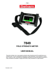
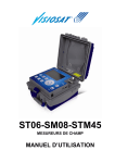
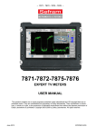
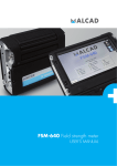
Download FIELD STRENGTH METERS USER MANUAL - HIK
Transcript
– 7806-7807-7808-7809-7846-7847 – 7806-7807-7808 7809-7846-7847 FIELD STRENGTH METERS USER MANUAL This product contains one or more programs protected under international and US copyright laws as unpublished works. They are confidential and proprietary to Dolby Laboratories. Their reproduction or disclosure, in whole or in part, or the production of derivative works there from without the express permission of Dolby Laboratories is prohibited. Copyright 2003-2005 by Dolby Laboratories. All rights reserved. Version: March 2012 M7806001A/04 – 7806-7807-7808-7809-7846-7847 – Versions Version and date of issue th 1.0 / October 4 2010 th 2.0 / November 8 2010 Modified chapter Nature of the change All Creation of the document 3.1, 3.2.9, Lists and setups spreadsheet dimmed. 5, Add setup number in lists. 8, 10.1, 10.2, 10.3, 10.4, Adding 7806, 7807 and 7808 for specific functions and measures. 12, Noise margin. 16.1, 16.2, 48Vrms input protection. 17.7, 20 th 3.0 / April 12 2011 2 Quick start modification. 2.1, Adding 7846. 3.1, 3.2.3, 3.2.8.3, 3.2.9, LNB screen modified. 4.2, Setup modification screen modified. 4.5, 4.5.1, Satellite technical data modified. 5, Chapter 4.5 and 4.5.1 deleted. 6, 7, 8, 9.1, 10, 10.1, 10.3, 10.4 11, 12, 13, 14.1, 16, 17.7, 17.9, 20.1, 20.4, 20.5, 20.6, 20.7, 20.9 th 4.0 / March 12 2012 1, 19, 20, 32, 43, 43, 46, Adding 7809 and 7847 47, 54, 57, §10, §11, §12, §16, §17, §20 §17.6 §17.7 Adding wheel threshold and backlight brightness §20.10 Battery discharge correction p. 2 – 7806-7807-7808-7809-7846-7847 – Thank you for purchasing this SEFRAM product and therefore trusting our company. Our different teams (research department, production, sales department, after-sales service…) are aiming at satisfying your wishes by designing and updating very advanced appliances. To obtain the best performance from this product please read this manual carefully. For more information please contact our different services: Sales department e-mail: sales@sefram.fr After-sales service e-mail: sav@sefram.fr Technical support e-mail: support@sefram.fr Fax: +33 (0)4 77 57 23 23 Website: www.sefram.fr Copyright Sefram, 2010. All rights reserved. Any total or partial reproduction of this document must be submitted for Sefram authorization. p. 3 – 7806-7807-7808-7809-7846-7847 – GARANTEE Your instrument is guaranteed for one year in parts and work time against any default of manufacture and/or contingencies in the functioning. This guaranty starts at the date of delivery and ends 365 calendar days later. If the appliance is subject to a guaranty contract, this contract cancels and replaces the above mentioned conditions of guaranty. This guaranty does not include any fault of use and/or error of handling. In case of use of the guaranty, the user must send back, with its expenses, the concerned appliance to our factory: SEFRAM Instruments & Systèmes Service Après-vente 32, rue Edouard MARTEL BP 55 42009 SAINT-ETIENNE CEDEX 2 The accessory items furnished as standard with the appliance (cables, plugs…), consumable items (battery…) and the optional accessory items (bag, case…) are guaranteed for 3 months against any default of manufacture. The warranty does not apply to LCD, pouch, keypad, etc. Please check our warranty conditions with our sales department. The warranty does not apply when the instrument is shocked. The factory options in the appliance are guaranteed for the same time as the appliance. Customer is responsible of shipping back the instrument to the factory. Special care must be taken in the packaging of the instrument to be sure that it will not be damaged during transportation. All necessary insurance must be taken by the customer. SEFRAM can reject any instrument damaged. What to do in case of malfunction? In case of malfunction or for any problem of use, please join the technical assistance by SEFRAM Instruments & Systems. A technician will take your call in charge and will give you any necessary information to solve your problem. What to do in case of crash? In case of crash of the appliance, please join our after-sales service. Some advice? Some technical help required? SEFRAM Instruments & Systems commits itself to help you by phone for the use of your appliance. Please phone: (00 33) 825 56 50 50 Technical help for products or send an e- mail to: support@sefram.fr p. 4 – 7806-7807-7808-7809-7846-7847 – 1 2 3 Important information .......................................................................................................... 9 1.1 Special precautions ........................................................................................................................................9 1.2 Security instructions .......................................................................................................................................9 1.3 Symbols and definitions .................................................................................................................................9 1.4 Conformity and restrictions of the appliance ................................................................................................10 Quick start .......................................................................................................................... 11 2.1 Catching of the terrestrial signal ...................................................................................................................12 2.2 Adjustment of the parameters in the Measurement screen .........................................................................13 2.3 Validation on TV ...........................................................................................................................................15 2.4 Set-up of the remote supply .........................................................................................................................16 2.5 Dish adjustment............................................................................................................................................17 Presentation ....................................................................................................................... 19 3.1 General .........................................................................................................................................................19 3.2 Description ...................................................................................................................................................21 3.2.1 Front side ................................................................................................................................................... 21 3.2.2 ON/OFF key ............................................................................................................................................... 21 3.2.3 Function keys ............................................................................................................................................. 21 3.2.4 Toolbox key ................................................................................................................................................ 22 3.2.5 Validation and Back keys ........................................................................................................................... 22 3.2.6 Connectors ................................................................................................................................................. 22 3.2.7 Contents of the screen ............................................................................................................................... 22 3.2.8 Man-machine interface .............................................................................................................................. 24 3.2.8.1 Modification of a parameter with the knob .....................................................................................24 3.2.8.2 Modification of a parameter with a list ...........................................................................................25 3.2.8.3 Line with several parameters .........................................................................................................26 3.2.8.4 Entering a name ............................................................................................................................27 3.2.8.5 Specific case of the spectrum analyzer .........................................................................................28 3.2.9 4 List of measurements and setups .............................................................................................................. 29 Set-up .................................................................................................................................. 33 4.1 Battery ..........................................................................................................................................................33 4.2 Loading the battery.......................................................................................................................................33 4.3 External power supply ..................................................................................................................................34 4.4 Start-up .........................................................................................................................................................34 4.5 Updating the software ..................................................................................................................................34 5 Setting the parameters of the measurement lists ........................................................... 37 6 Library setups .................................................................................................................... 41 7 Spectrum analyzer ............................................................................................................. 45 8 Dish adjustment (7808-7846-7847).................................................................................... 47 8.1 Updating the satellites ..................................................................................................................................47 8.2 Dish adjustment process ..............................................................................................................................49 p. 5 – 7806-7807-7808-7809-7846-7847 – 8.3 9 Control of the satellite ...................................................................................................................................51 Level / Power Measurement .............................................................................................. 53 9.1 Modification of the parameters .....................................................................................................................54 9.2 Measurements according to the standard ....................................................................................................54 9.2.1 Terrestrial band .......................................................................................................................................... 54 9.2.2 Satellite band ............................................................................................................................................. 55 9.3 10 Thresholds ....................................................................................................................................................56 Measurement of error rates ............................................................................................ 57 10.1 DVB-T/H (7806-7809-7846-7847) ............................................................................................................58 10.2 DVB-T2 (7809-7847) ................................................................................................................................59 10.3 DVB-C (7807-7809) and MCNS (7807) ....................................................................................................60 10.4 DVB-S and DSS (7808-7846-7847) .........................................................................................................61 10.5 DVB-S2 (7808-7846-7847) .......................................................................................................................62 11 Constellation ................................................................................................................... 63 12 Echo - Guard interval (7806-7809-7846-7847) ............................................................... 65 13 Measurement map........................................................................................................... 67 13.1 14 Values out of tolerance .............................................................................................................................69 Image and Sound ............................................................................................................ 71 14.1 Digital TV ..................................................................................................................................................71 14.2 Service list ................................................................................................................................................72 14.3 Setup change ............................................................................................................................................73 14.4 Audio .........................................................................................................................................................73 15 Saving .............................................................................................................................. 75 16 Remote supply / LNB – DiSEqC ..................................................................................... 77 16.1 Terrestrial band (7806, 7807 & 7809).......................................................................................................77 16.2 Satellite band (7808).................................................................................................................................77 16.2.1 Switches ..................................................................................................................................................... 78 16.2.2 Positioner ................................................................................................................................................... 80 16.2.3 SatCR mode............................................................................................................................................... 80 16.3 17 16.2.3.1 Automatic research of the frequencies of slots..............................................................................82 16.2.3.2 Influence of the SatCR mode on the spectrum analyzer ...............................................................82 Terrestrial + satellite band (7846-7847) ...................................................................................................83 Configuration................................................................................................................... 85 17.1 Language ..................................................................................................................................................85 17.2 Measurement unit .....................................................................................................................................85 17.3 Sound level of the beep for the keys and the plotting ..............................................................................85 17.4 Background colour of the graphical pages ...............................................................................................85 17.5 Active USB port ........................................................................................................................................86 17.6 Wheel threshold ........................................................................................................................................86 17.7 LCD backlight ...........................................................................................................................................86 p. 6 – 7806-7807-7808-7809-7846-7847 – 17.8 Memories ..................................................................................................................................................86 17.9 Configuration with USB key ......................................................................................................................91 17.10 Filling library setups with ini file ................................................................................................................93 17.11 Factory reset .............................................................................................................................................95 17.12 Update ......................................................................................................................................................95 18 Displayed messages ....................................................................................................... 97 18.1 Alert messages .........................................................................................................................................97 18.2 Impossibility messages .............................................................................................................................98 18.3 Error messages ........................................................................................................................................99 19 Maintenance .................................................................................................................. 101 20 Technical data ............................................................................................................... 103 20.1 Common technical characteristics ..........................................................................................................103 20.2 DVB-C (7807-7809) ................................................................................................................................104 20.3 MCNS (7807) ..........................................................................................................................................104 20.4 DVB-S, DSS (7808-7846-7847) .............................................................................................................104 20.5 DVB-S2 (7808-7846-7847) .....................................................................................................................105 20.6 DVB-T/H (7806-7809-7846-7847) ..........................................................................................................105 20.7 DVB-T2 (7809-7847) ..............................................................................................................................106 20.8 Demodulation image and sound .............................................................................................................106 20.9 Remote supply ........................................................................................................................................106 20.10 Power supply - Battery............................................................................................................................106 20.11 Environment............................................................................................................................................107 20.12 Accessories ............................................................................................................................................107 20.13 Equivalence between V, dBµV, dBmV and dBm ....................................................................................108 20.14 Values to measure ..................................................................................................................................108 21 Terminology .................................................................................................................. 109 p. 7 – 7806-7807-7808-7809-7846-7847 – p. 8 – 7806-7807-7808-7809-7846-7847 – 1 Important information Please read cautiously the following instructions before using this appliance 1.1 Special precautions Do not use the product for any purpose else that scheduled. Use the battery charger provided to prevent any damage to the appliance and guarantee its measurement characteristics. Do not use in a wet environment. Do not use in an explosive environment. Only a qualified personal should be allowed to work on the appliance in case of failure or for maintenance. In such a case, it is necessary to use Sefram spare parts. Do not open the appliance: risk of electrical shock. You must use only the provided BNC/F convertor furnished with your appliance. Using any other convertor may damage your appliance and invalidates the guarantee. 1.2 Security instructions For a good use of the appliance, you must respect the security and use instructions as described in this manual. Some specific warnings are specified all along this manual. In case of need, warning symbols are stamped in the appliance: 1.3 Symbols and definitions Symbols that appear in this user manual: Remark: important information Symbols that appear on the appliance: Caution: Refer to the user manual. Risk of damage to any material connected to the instrument or to the instrument itself. Grounding: Easily reached parts linked to the grounding. Product to recycle. p. 9 – 7806-7807-7808-7809-7846-7847 – 1.4 Conformity and restrictions of the appliance See chapter “CE Declaration”. p. 10 – 7806-7807-7808-7809-7846-7847 – 2 Quick start Important keys: Toolbox: For the set-up of the satellite remote supply Spectrum: For fast identification of a signal Measurement: For a fine adjustment of the parameters TV: For the complete validation of the reception Validation: To select a value to modify KNOB: To adjust this value p. 11 – 7806-7807-7808-7809-7846-7847 – 2.1 Catching of the terrestrial signal Push the Spectrum key Push several times on the Validation key to select the Span: 820MHz parameter Rotate the knob to display Span: 20 MHz Push several times on the Validation key to select the Channel 21 (E21) parameter p. 12 – 7806-7807-7808-7809-7846-7847 – Rotate the knob to get an active channel in the 50 (E50) screen 2.2 Adjustment of the parameters in the Measurement screen Push the MEASUREMENT key Rotate the knob to select the standard p. 13 – 7806-7807-7808-7809-7846-7847 – Push the Validation key to select Rotate the knob to modify the standard Push the Validation key to select the bandwidth Rotate the knob for modification if required p. 14 – 7806-7807-7808-7809-7846-7847 – 2.3 Validation on TV Push on the TV key p. 15 – 7806-7807-7808-7809-7846-7847 – 2.4 Set-up of the remote supply Multiple push on the Toolbox key give you access to the Remote supply screen Push the Validation key to select the Remote supply parameter Rotate the knob to display On or auto Push the Validation key p. 16 – 7806-7807-7808-7809-7846-7847 – 2.5 Dish adjustment 1/ Connect the dish to the appliance. 2/ Set up the remote supply (see Set-up of the remote supply) 3/ Push twice on the Spectrum key to access the pointing mode. (The appliance already has a list of satellites included) 4/ Choose the satellite to plot (see Pointing) 5/ Slowly direct the dish until you hear the locking signal and get the best quality. No transponder found → red smiley Medium reception quality (< 50%) → orange smiley Good reception quality (> 50%) → green smiley Remember: transponder = satellite channel p. 17 – 7806-7807-7808-7809-7846-7847 – Caution: To accurately identify a satellite, you have to « catch » it on all 4 transponders (Quality > 0) However, some transponders are regularly modified. Consult the frequency plan of the satellite if the transponder does not seem to work. Some switches or LNB only work with DiSEqC commands. In this case, set the band (OL) and the polarization on DiSEqC at the LNB-DiSEqC configuration page (Caution: the pointing is slower when you use the DiSEqC command). For any additional information, our technical support is available: E-mail: support@sefram.fr p. 18 – 7806-7807-7808-7809-7846-7847 – 3 Presentation 3.1 General The field measurement appliances 7806, 7807, 7808, 7809, 7846 and 7847 are portable appliances designed for the installation and the maintenance of any device for the broadcasting and reception of analogical, terrestrial digital, satellite television or cable network. The frequency band ranges from 5MHz to 2150MHz; they allow accurate measurements on all standards of analogical televisions, the FM carrier waves and the various digital standards NICAM, DVB-C, MCNS, DVBT/H, DVB-T2, DVB-S, DSS and DVB-S2. They make Level measurements as average measurements, peak measurements or power according to the selected standard, on the video carrier wave and the audio carrier waves if they exist. In Measurement Plan mode, they scan up to 50 setups simultaneously and compare them to decision thresholds (min. / max.) With their effective measurement of Error rate (various BER, MER); they enable the complete validation of the digital transmissions DVB-T/H, DVB-T2, DVB-C, MCNS, DVB-S, DSS and DVB-S2. The graphic display of the Constellation in DVB-T/H, DVB-T2, DVB-C, MCNS, DVB-S, DSS and DVB-S2 and the display of echoes in DVB-T/H and DVB-T2 allow the fulfilment of this analysis. The quick and accurate Spectrum analysis shows the interference waves... You can visualize the unencrypted image of terrestrial digital or satellite TV in SD and HD. You can hear digital sound with an incorporated loudspeaker. The large amount of FLASH memory allows the storage of many measurements and spectrum curves. Designed for a use on field, they are compact (less than 1.5kg, battery included), unattended (pack battery and quick charger), equipped with a back lighted colour LCD display for a better visibility. The capabilities of your appliance are summed-up below. p. 19 – 7806-7807-7808-7809-7846-7847 – 7806 model: Compatible with terrestrial signals Analogical and digital measurements DVB-T/H unencrypted SD/HD digital images and sounds 5, 13, 18 and 24Volt remote supply 7807 model: Compatible with cable signals Analogical and digital measurements DVB-C, MCNS unencrypted SD/HD digital images and sounds 5, 13, 18 and 24Volt remote supply 7808 model: Compatible with satellite signals Analogical and digital measurements DVB-S, DSS and DVB-S2 unencrypted SD/HD digital images and sounds 13/18Volt remote supply, ToneBurst, DiSEqC 1.2 and SatCR 7809 model: Compatible with cable and terrestrial signals Analogical and digital measurements DVB-C, DVB-T and DVB-T2 unencrypted SD/HD digital images and sounds 5, 13, 18 and 24Volt remote supply 7846 model: Compatible with terrestrial and satellite signals Analogical and digital measurements DVB-T/H, DVB-S, DSS and DVB-S2 unencrypted SD/HD digital images and sounds 5, 13, 18 and 24Volt terrestrial remote supply 13/18Volt satellite remote supply, ToneBurst, DiSEqC 1.2 and SatCR 7847 model: Compatible with cable, terrestrial and satellite signals Analogical and digital measurements DVB-T/H, DVB-T2, DVB-S, DSS and DVB-S2 unencrypted SD/HD digital images and sounds 5, 13, 18 and 24Volt terrestrial remote supply 13/18Volt satellite remote supply, ToneBurst, DiSEqC 1.2 and SatCR p. 20 – 7806-7807-7808-7809-7846-7847 – 3.2 3.2.1 Description Front side Remote supply lamp Color screen 16/9 Toolbox key Validation key ON/OFF key Knob Back key Function keys 3.2.2 Battery charge lamp ON/OFF key This key turns the appliance on and off. The appliance will stop automatically after ten minutes on the splash page. If the appliance gets locked, push it about ten seconds to stop it. 3.2.3 Function keys PARAMETERS: selection and change of the measurement lists; pushing it twice gives you access to the library of the 1000 software listings available and to their modification SPECTRUM: spectrum analysis; pushing it twice gives you access to the satellite adjustment mode; pushing it three times gives you access to the display of the identification of the satellite (according to the type of the appliance). MEASUREMENT: level measurement (peak, average and power) Pushing twice: measurement of BER and MER (according to the selected standard) Pushing three times: display of the satellite constellation (according to the selected standard) Pushing four times: display of the echoes (according to the selected standard and the type of the appliance) Pushing five times: display of the measurement plan TV: display of the digital image; the knob enables you to set the sound volume Pushing twice: display of the list of services Pushing three times: display of the pending setup p. 21 – 7806-7807-7808-7809-7846-7847 – 3.2.4 Toolbox key According to the context, this key gives you access to secondary functions of the appliance. If no parameter has been selected (yellow colour) and a measurement or a spectrum is displayed, it gives you access to the storage of this measurement or this spectrum. Pushing it twice gives you access to the remote supply. Pushing it three times gives you access to the configuration of the appliance If a parameter has been selected, this key can give you access to a list of selections. 3.2.5 Validation and Back keys Validation: this key enables the selection of parameters and the validation of your choice Back: this key enables the de-selection of parameters, the cancellation of a choice and the closing of a list. 3.2.6 Connectors All connectors are located together on the right side of the appliance. Power supply connector Measurement input Functioning with the mains or loading of the battery Interchangeable BNC or F plug Mini-B type USB connector Type A USB connector Connection to the computer USB key for configuration or updating of the software BNC or F plug 3.2.7 Contents of the screen p. 22 – 7806-7807-7808-7809-7846-7847 – All useful information is gathered on the same screen. Example: Measurement of the level-power of the satellite. Title of the page Name of the site DiSEqC / SatCR information Charge status of the battery Mini spectrum Measurement parameters Signal width Cursors Bargraphs Measurements p. 23 – 7806-7807-7808-7809-7846-7847 – 3.2.8 Man-machine interface 3.2.8.1 Modification of a parameter with the knob Push the Measurement key The Measurement page appears With the knob, select the Setup line (white on grey) Push the Validation key The name of the setup is selected (black on yellow): now you can change it Rotate the knob to change the name of the setup; the parameters of the new setup are automatically recalled p. 24 – 7806-7807-7808-7809-7846-7847 – Push the Back key The name of the setup is no more selected; turning the knob will change the line but no more the setup 3.2.8.2 Modification of a parameter with a list Push the Validation key, then push the Toolbox key The list of the available setups appears. The knob enables you to move along the list Push the Validation key The setup is recalled, the name of the setup is no more selected p. 25 – 7806-7807-7808-7809-7846-7847 – 3.2.8.3 Line with several parameters Push the Validation key The first parameter is selected; you can change it with the knob. Push the Validation key once again The second parameter is selected; you can change it with the knob. Push the Validation key for the third time The third parameter is selected; you can change it with the knob. Push the Validation key for the fourth time; no parameter is selected any more Pushing the Back key deselects the active parameter at any time p. 26 – 7806-7807-7808-7809-7846-7847 – 3.2.8.4 Entering a name Push the Toolbox key The Save window appears. Push the Validation key The first character of the name is selected Turning the knob makes you change the character Pushing the Validation key leads to the following character After eight characters, you can save the name by pushing the Validation key. Pushing the Back key cancels the save procedure at any time. p. 27 – 7806-7807-7808-7809-7846-7847 – If the end of the name is a series of numbers, they will be automatically incremented at the next save. The last used name is saved even at the shutdown of the appliance. 3.2.8.5 Specific case of the spectrum analyzer Pushing the Validation or Back key leads you to the next/previous parameter Frequency of the cursor Setup Channel or polarization Reference level Number of dB/division Central frequency Span width You can change the selected parameter with the knob (black on yellow). p. 28 – 7806-7807-7808-7809-7846-7847 – 3.2.9 List of measurements and setups In order to make the call of information easier on the field, the appliance uses 20 lists of measurements, 50 lines each, 1000 setups each. A setup corresponds with a terrestrial, cable or satellite emission. A list of measurements corresponds with a specific installation: presence of several dishes, of various switches… The same setup can be used in several measurement lists. An installation can use two dishes: ASTRA 19.2 in DiSEqC position A HOT BIRD 13 in DiSEqC position B Another installation can use three dishes: ATLANTIC BIRD 3 in DiSEqC position A ASTRA 1 in DiSEqC position B HOT BIRD in DiSEqC position C The same setup can be used several times in the same list of measurements: ZDF SatCR slot 0 ZDF SatCR slot 1 ZDF SatCR slot 2 ZDF SatCR slot 3… If a parameter of a setup is changed, by example a change of the bandwidth or a change from DVB-S to DVB-S2, only the setup in the library has to be updated. You can create these lists and setups with a computer on spreadsheet software and upload them into the appliance thanks to an USB key. A measurement list includes: the name of the list on 10 characters the lower frequency of the LNB (OL1) the higher frequency of the LNB (OL2) the selection mode lower band / higher band of the LNB the selection mode of the polarisation the presence and the position number of the position finder (for motorized dishes) 50 lines, each including: a setup number corresponding with the list of setups the presence and the functioning mode of a switch of the committed type the position of the switch of the committed type the presence and the functioning mode of a switch of the uncommitted type the position of the switch of the uncommitted type the presence of a SatCR item p. 29 – 7806-7807-7808-7809-7846-7847 – the number of the SatCR slot the position of the SatCR switch. Some of these parameters are specific to the satellite band and have no influence on the terrestrial and cable modes. Push the Parameters key Rotate the knob to select a line in the list Push the Validation key to open the modification page Display of a list of measurements in spreadsheet software: p. 30 – 7806-7807-7808-7809-7846-7847 – A setup is made of: a setup name in 8 characters a site name in 10 characters a frequency a channel number for terrestrial band or cable a frequency plan for terrestrial band or cable a vertical or horizontal polarisation for satellite band a lower and higher LNB band for satellite band a standard an analogical audio mode mono/stereo/NICAM for terrestrial band or cable a type of constellation 64QAM 256QAM in DVB-C or MCNS a bandwidth 5, 6, 7 or 8 MHz in DVB-T and DVB-T2 a symbol output in DVB-C, MCNS, DVB-S, DVB-S2 or DSS a value for the guard interval in DVB-T and DVB-T2 the inversion or not of the spectrum in DVB-T A few parameters have no influence according to the terrestrial, cable or satellite band or according to the standard. The name of the site allows you to distinguish two different emitters, ex. TF1 Fourvière and TF1 Chambéry. Frequency and channel number are equivalent: valid channel numbers take priority over frequencies. The frequency plan parameter associated with the setup enable users close to boundaries to keep on using their channel numbers. Selecting a List on the Measurement Lists page calls back automatically all information assigned to this list. Selecting a Setup on one of these measurement pages calls back automatically all information assigned to this setup. Push twice on the Parameters key Rotate the knob to select a setup in the list Push the Validation key to open the modification page p. 31 – 7806-7807-7808-7809-7846-7847 – Display of a list of setups in spreadsheet software: With 7846 and 7847 models, you can create a list with satellite and terrestrial setups: p. 32 – 7806-7807-7808-7809-7846-7847 – 4 Set-up All the material is proofed and checked before shipping and furnished in an adapted package. There are no particular instructions about unpacking. The appliance is equipped with a lithium-ion battery (Li-ion). It is shipped with a loaded battery. However, if the appliance has not worked for more than a month, you should check the status of charge of the battery and reload it if necessary. 4.1 Battery Caution: You need to dismantle the appliance for any intervention on the battery. Only a SEFRAM technician must operate such dismantlement. Only use batteries provided by SEFRAM. Security advice: Do not throw the pack battery into the fire; do not heat it Do not shunt the elements of the battery: risk of explosion! Do not pierce it Do not disassemble the pack battery Do not reverse the polarities of the battery The pack battery includes a protection item that should not be damaged or removed Do not stock the pack in a hot place Do not damage the protection casing of the pack Do not stock the pack in a vehicle that may be exposed to direct sunlight. The life of the battery is 200 loading/unloading cycles or 2 years. Advice for a longer life of your battery: Do not unload it too much Do not stock the batteries too long without using them Stock the battery with ca. 40% loading Do not load or unload completely the battery before shelf. When the battery is nearly completely unloaded, the appliance shows a “Battery unloaded” message, then turns off automatically after a few minutes. 4.2 Loading the battery To load the battery in the appliance: Connect the external power supply provided on the jack plug of the appliance (on the right) Connect the power supply to the mains. The internal charger starts loading the battery; the orange light BAT turns on. p. 33 – 7806-7807-7808-7809-7846-7847 – The appliance must be off during this loading. When the battery is loaded, the BAT light will turn off. It takes 1 hour 30 minutes to load the battery up to 80%. The total loading requires 2 hours 15 minutes. The typical working capacity is 3 hours 30 minutes for a 7806, 3 hours 50 minutes for a 7807, 2 hours 15 minutes for a 7808 with working remote supply (display of a HD picture), 3 hours 15 minutes for a 7809, 2 hours 10 minutes for 7846 with working remote supply (display of a HD picture) and 1 hour 50 minutes for 7847 with working remote supply (display of a HD picture) 4.3 External power supply You can supply the appliance with an external power source under continuous voltage. The appliance works under 15V (1A). The charger block provided when you bought the appliance is also an external power supply. 4.4 Start-up Push the ON/OFF key on the front keyboard. The introduction window appears on screen. The message “Self test: in progress” is shortly displayed before clearing. 4.5 Updating the software You can easily update the software to get new functions. The update process requires an USB key. Download the update file FIRM_vX.X.BIN on our website (www.sefram.fr): http://www.sefram.com/www/NP_D_SOFTWARE.asp Insert an USB key in your PC. Copy this file on the home directory of the key. Pull out the USB key. Turn the appliance on: Check that the battery status is sufficient (> 30%). You'd better connect the appliance to the mains with the provided adapter. Push the Toolbox key to get the Configuration page. Check that the active USB port is the USB port A and that nothing is connected to the USB port mini B. p. 34 – 7806-7807-7808-7809-7846-7847 – Insert the USB key into the connector of the appliance. Turn the knob to select Software update. Push the Validation key p. 35 – 7806-7807-7808-7809-7846-7847 – Caution: Do not turn the appliance off during the updating process The updating process lasts ca. 3 minutes 30 seconds. At the end of the updating process, the appliance invites you to push the ON/OFF key. The software is now uploaded into your appliance. A few error messages may appear: Do not take them into account. p. 36 – 7806-7807-7808-7809-7846-7847 – 5 Setting the parameters of the measurement lists Pushing the PARAMETERS key gives you access to the Parameters function: In this page, you can change of measurement list, modify the name of the list, modify the parameters of a line, erase the data of a line and erase all data in the measurement list. Selection of an active measurement list among the twenty available ones Push the Validation key Rotate the knob to change of list Push the Back key When the list number is selected, you can also use the Toolbox key to display a selection list p. 37 – 7806-7807-7808-7809-7846-7847 – Modification of the name of the list Push the Validation key to select the character to modify. Rotate the knob to change the character Push the Validation key to select the following character. Push the Validation key to validate the new name Modification of data Rotate the knob to reach the line to modify Push the Validation key to open the List modification page You can change data after selection of the affected line thanks to the knob and after pushing the Validation key p. 38 – 7806-7807-7808-7809-7846-7847 – The Delete line cancels all data in the current line. The Delete all line cancels all data in the current line (confirmation required). In terrestrial band or cable band, only the number of the setup matters. In satellite band, there are also switches of committed and uncommitted type and the SatCR mode. With 7846 and 7847 models, you can create a list with satellite and terrestrial setup: p. 39 – 7806-7807-7808-7809-7846-7847 – p. 40 – 7806-7807-7808-7809-7846-7847 – 6 Library setups Pushing twice on the Parameters key gives you access to the Setup list function: In this page, you can create a new setup, change the parameters of a setup, erase data in a setup and erase the data of all setups. Modification of the data in a setup Rotate the knob to reach the setup to modify Push the Validation key to open the Setup modification page You can modify data after selection of the line to change with the knob and the Validation key The band line allows choosing the frequency band. The Delete line cancels all data in the current line. The Delete all line cancels all data in the current line (confirmation required). p. 41 – 7806-7807-7808-7809-7846-7847 – According to the terrestrial, cable or satellite band and to the selected standard, the content of the page is different. p. 42 – 7806-7807-7808-7809-7846-7847 – The « band » parameter allows choosing between these frequencies ranges: Ter.: Terrestrial Sat. L: Satellite L band (950 MHz-2150MHz) Sat. Ku: Satellite Ku band (10700-12750MHz) Sat. C: Satellite C band (3000-4200MHz) 7806, 7807: Terrestrial band only. (This parameter can’t be modified) 7808: Satellite C band + L band + Ku band. 7846, 7847: Terrestrial band + Satellite C band + L band + Ku band. For 7846 and 7847 models, (allowing terrestrial or satellite setups) it’s possible to change from terrestrial to satellite by: - changing the frequency band - changing the frequency - changing the standard p. 43 – 7806-7807-7808-7809-7846-7847 – p. 44 – 7806-7807-7808-7809-7846-7847 – 7 Spectrum analyzer Pushing the Spectrum key gives you access to the Spectrum analyzer function: In terrestrial band or cable band, the analysis filter is 300 kHz wide. You can move the cursor along the frequency range, channel per channel or setup per setup. You access the various setups with the Validation key; you change them with the knob. In satellite band, the analysis filter is 1MHz wide. You can directly change the polarization and the band, hence an easier adjustment of the counter-polarization. In SatCR mode, two reddotted lines indicate the width of the slot. If the measurement list includes setups with all possible slots, you can display them very easily by simply changing of setup. The current slot number is displayed on the upper right of the screen. You can change the following parameters: p. 45 – 7806-7807-7808-7809-7846-7847 – The frequency of the cursor The number of the setup The number of the channel or the polarization and the band The reference level The number of dB/division The central frequency The span width (span) The default position of the input pad is in automatic mode. Any change of the reference level stops the automatic mode. Only a return to the Spectrum page will re-launch it. In manual input pad mode, the input level must be lower than Att + 50 dBµV to prevent any saturation of the input and any false representation. Example: To correctly display an 110dBµV signal, you need a 60dB pad. For 7846 and 7847 models, (allowing terrestrial and satellite setups) it’s possible to change from terrestrial to satellite in spectrum by: - changing frequency with the knob - changing the setup p. 46 – 7806-7807-7808-7809-7846-7847 – 8 Dish adjustment (7808-7846-7847) Only in Satellite band The dish adjustment mode enables you to quickly orientate the dish with the initial selection of the satellite to receive. Push the Spectrum key twice to access to the Dish adjustment function. Name and position of the satellite Indication of global quality Supply intensity of the LNB Frequency, polarization, band, level and quality The appliance has 32 orbital positions available for satellites. About 10 satellites are specified at delivery. 4 transponders are associated to each satellite. Use the Validation key 8.1 and the knob to change of satellite. Updating the satellites You can now add new satellites and update or erase old ones with a computer and a USB key. p. 47 – 7806-7807-7808-7809-7846-7847 – Open the Sat.xls file with a spreadsheet software (the file is available on our website) http://www.sefram.com/www/NP_D_SOFTWARE.asp Change the values as required. The locking time depends on the transponder rate. The lower the rate, the longer the locking time. Thus, you'd better choose high rate transponders to align the dish. Save the file. Save the file once again under CSV format; call it Sat.csv. There is a CSV macro-command that does it all: Ctrl + Shift + C on keyboard. (Office 2007 2010 only) Copy the Sat.csv file on the home directory of the USB key. Push the Toolbox key until reaching the Configuration page. Check that the active USB port is the port USB A, and that nothing is connected to the USB port mini B. p. 48 – 7806-7807-7808-7809-7846-7847 – Insert the USB key into the connector of the appliance. Turn the knob to select the line Config. <-> USB. Push the Validation key The previous configuration is saved on the key; the new one is transferred to the appliance. 8.2 Dish adjustment process Procedure: 1/ Connect the dish to the appliance; turn it on. 2/ Validate the remote supply: - The VDC light turns on the front side. - Check the supply intensity of the LNB (about 50 to 200 mA). p. 49 – 7806-7807-7808-7809-7846-7847 – 3/ Select the satellite for alignment in the list (with the knob). 4/ Slowly turn the dish until you get the highest level and hearing the locking signal. 5/ Slightly turn the LNB to get the highest quality (counter-polarization). You can hear a melody as soon as the first transponder has been found; then, you will hear beeps. The higher the quality, the more frequent these beeps. If the appliance has not been synchronized on all four transponders, the quality indicator is red. If the appliance is synchronized on all four transponders but the reception quality is medium, it is orange. If the appliance is synchronized on all four transponders and if the reception quality is good, it is green. Caution: To identify a satellite, the appliance must be synchronized on all 4 transponders. However, some transponders are regularly modified. Consult the frequency plan of the satellite when the transponder does not seem to work. Some switches or LNB only work with DiSEqC commands. In this case, position the OL and the polarization on DiSEqC at the LNB-DiSEqC configuration page (Caution: the orientation will be slower if you use the DiSEqC command). p. 50 – 7806-7807-7808-7809-7846-7847 – 8.3 Control of the satellite To check if the selected satellite is the one you want: push the Spectrum key Then, the appliance looks for the MPEG NIT table on one of the 4 transponders and displays the name of the satellite: Caution: The displayed name depends on the content of the MPEG NIT table. Some providers do not (or badly) furnish this table. The displayed information may be wrong. p. 51 – 7806-7807-7808-7809-7846-7847 – p. 52 – 7806-7807-7808-7809-7846-7847 – 9 Level / Power Measurement Pushing the Measurement key gives you access to the Level measurement function. It is thus possible to make a level measurement at a specified frequency with a detection mode adapted to the standard. You can either make measurements on a saved setup (see chapter Setting the parameters of the measurement lists) or modify each parameter manually. In terrestrial band, for a user plug, the level should be: - between 50 and 66 dBµV in FM - between 35 and 70 dBµV in DVB-T/H and DVB-T2 - between 57 and 74 dBµV in any other case. In satellite band, for a user plug, the level should be: - between 47 and 77 dBµV. Terrestrial band Satellite band p. 53 – 7806-7807-7808-7809-7846-7847 – 9.1 Modification of the parameters The various parameters are: The number of the setup The number of the channel and the corresponding frequency plan for the terrestrial and cable band or the polarization and the band for the satellite. Caution: The vector of these commutations is the remote supply; the 22kHz modulation or DiSEqC is superimposed on the continuous voltage generated by the appliance. The frequency of the emitter or the transponder (and the real frequency in satellite) The standard and the bandwidth for the DVB-T/H and DVB-T2 The audio mode for the analogical TV The symbol rate for the digital TV. For 7846 and 7847 models, (allowing terrestrial and satellite setups) it’s possible to change from terrestrial to satellite in level/power measurement by: - changing frequency - changing standard - changing the setup (from terrestrial to satellite setup) See chapter Man-machine interface for any modification. 9.2 Measurements according to the standard The appliance makes various measurements according to the valid standard. The available measurements are Average, Peak and Power. 9.2.1 Terrestrial band The appliance automatically makes level measurements on the Video carrier wave and on 1 or 2 Sound carrier waves according to the selected Audio mode. p. 54 – 7806-7807-7808-7809-7846-7847 – The table below lists the measurement types and the frequencies of the audio carrier waves of each standard: Standard BG Video carrier wave negative, AM DK negative, AM I positive, AM L positive, AM MN negative, AM Measure Sound carrier waves Peak Peak Peak Peak Peak DVB-C Digital Power MCNS Digital Power DVB-T/H Digital Power DVB-T2 Digital Power FM FM Average Carrier Non modulated Average Mono Stereo NICAM FM FM DQPSK 5.5 MHz 5.74 MHz 5.85 MHz FM FM DQPSK 6.5 MHz 6.258 MHz 5.85 MHz FM DQPSK 6.0 MHz 6.552 MHz AM DQPSK 6.5 MHz 5.85 MHz FM FM 4.5 MHz 4.72 MHz The appliance displays the level of the Video carrier wave, the ratio(s) Video/Audio and the ratio C/N. The display is made of one to four measures and bar graphs. The measurement of the Audio carrier waves is always an Average measurement. 9.2.2 Satellite band Standard Video carrier wave Measurement PAL FM Peak SECAM FM Peak NTSC FM Peak DVB-S Digital Power DSS Digital Power DVB-S2 Digital Power p. 55 – 7806-7807-7808-7809-7846-7847 – 9.3 Thresholds Predefined thresholds are used to specify if the measurement is pertinent. Standard Min. Max. Analogue TV 57 74 DVB-C, MCNS 57 74 DVB-T/H, DVB-T2 35 70 FM, carrier wave 50 66 Satellite analogical TV 47 77 DVB-S, DSS 47 77 DVB-S2 47 77 Decision thresholds are used for the display of the measurements « Power Level » and « Measurement Plan »: Min. threshold Max. threshold measurements: red display green display p. 56 orange display – 7806-7807-7808-7809-7846-7847 – 10 Measurement of error rates gives you access to the Measurement of error Pushing several times on the Measurement key rates function. The displayed values are the different BER (Bit Error Rate), the PER (Packet Error Rate) and the MER (Modulation Error Ratio) in DVB-T/H, DVB-T2, MCNS, DVB-C, DVB-S, DVB-S2 or DSS. The bar graphs are displayed in colours according to the measurement values for the error rates: - GREEN: right error rates - ORANGE: BERo > 1-4 (QEF: Quasi Error Free) without lost packet - RED: lost packets (PER) The Automatic Frequency Control (AFC) is automatically activated in case of measurement of error rates. These measures are available if one of these standards is in process in the Level measurement page: DVB-T/H (7806, 7809, 7846, 7847) DVB-T2 (7809, 7847) DVB-C (7807, 7809), MCNS (7807 only) DVB-S, DSS, DVB-S2 (7808, 7846, 7847) The parameters on this page are the same as on the page Level measurement with additional parameters specific to each modulation. The "Sync ?" message specifies that the signal is absent or not locked; check its presence, the modulation parameters, the remote supply and the LNB and DiSEqC parameters in satellite band. X The sign < before an error rate value means that there were no error but 10 bits have E-8 E8 been tested (ex. <1 means 1 bits have been tested). For 7846 and 7847 models, (allowing terrestrial and satellite setups) it’s possible to change from terrestrial to satellite in measurement of error rate by: - changing frequency - changing standard - changing the setup (from terrestrial to satellite setup) p. 57 – 7806-7807-7808-7809-7846-7847 – 10.1 DVB-T/H (7806-7809-7846-7847) TUNER DEMODULATOR VITERBI BERi REED SOLOMON BERo DECODING MPEG PER Display of the values: BERi: error rate before Viterbi BERo: error rate after Viterbi PER: error rate after Reed Solomon (packet error rate) MER: modulation error rate NM: noise margin BERx: ‘bits’ error rate Ratio of the number of erroneous bits / number of transmitted bits during the measuring time PER: ‘packets’ error rate Ratio of the number of erroneous packets / number of transmitted packets during the measuring time Remember: a packet in DVB-T/H is made of 204 bytes; a packet is ‘wrong’ if it includes more than 8 wrong bytes (correction by Reed Solomon coding). Display of the detected Modulation type: number of carrier waves (8 K) constellation (64QAM) guard interval (1/32 auto) Viterbi rate (2/3) spectrum inversion. In case of poor quality signal or co-frequent analogical signal, you'd better choose the manual front guard interval mode. To do this, you had to change the “Modulation” parameter by choosing the good guard interval. The display of the value of Cell_ID indicated by the provider and specific to the emitter. p. 58 – 7806-7807-7808-7809-7846-7847 – 10.2 DVB-T2 (7809-7847) TUNER DEMODULATOR LDPC BERi BCH BERo DECODING MPEG PER Display of the values: BERi : error rate before LDPC BERo : error rate after LDPC PER : error rate after BCH (lost packets) MER : modulation error rate LKM: link margin Remember: LDPC: Low Density Parity Check BCH: Bose Chauhuri Houquenohem In DVB-S2, the concatenation LDPC + BCH has replaced the concatenation Viterbi + Reed Solomon of the correction of the DVB-S. Display of the detected Modulation type: number of carrier waves (32 K) constellation (256QAM R) guard interval (1/8) rate (3/5) The display of the values of Network_ID, System_ID and Cell_ID indicated by the provider and specific to the emitter p. 59 – 7806-7807-7808-7809-7846-7847 – 10.3 DVB-C (7807-7809) and MCNS (7807) TUNER DEMODULATOR REED SOLOMON BERo DECODING MPEG PER Display of the values: BERo : error rate before Reed Solomon PER : error rate after Reed Solomon (packet error rate) MER : modulation error rate NM: noise margin BERo: ‘bits’ error rate Ratio of the number of erroneous bits / number of transmitted bits during the measuring time PER: ‘packets’ error rate Ratio of the number of erroneous packets / number of transmitted packets during the measuring time Remember: a packet in DVB-C is made of 204 bytes; a packet is ‘wrong’ if it includes more than 8 wrong bytes (correction by Reed Solomon coding). p. 60 – 7806-7807-7808-7809-7846-7847 – 10.4 DVB-S and DSS (7808-7846-7847) TUNER DEMODULATOR VITERBI BERi REED SOLOMON BERo DECODING MPEG PER Display of the values: BERi : error rate before Viterbi BERo : error rate after Viterbi PER : error rate after Reed Solomon (packet error rate) MER : modulation error rate LKM: link margin BERx: ‘bits’ error rate Ratio of the number of erroneous bits / number of transmitted bits during the measuring time PER: ’packets’ error rate Ratio of the number of erroneous packets / number of transmitted packets during the measuring time Remember: a packet in QPSK (DVB-S) is made of 204 bytes; a packet is ‘wrong’ if it includes more than 8 wrong bytes (correction by Reed Solomon coding). In DSS, a packet is made of 146 bytes. Display of the detected Modulation type: the constellation (QPSK) the Viterbi rate (3/4) p. 61 – 7806-7807-7808-7809-7846-7847 – 10.5 DVB-S2 (7808-7846-7847) TUNER DEMODULATOR LDPC BERi BCH BERo DECODING MPEG PER Display of the values: BERi : error rate before LDPC BERo : error rate after LDPC PER : error rate after BCH (lost packets) MER : modulation error rate LKM: link margin Remember: LDPC: Low Density Parity Check BCH: Bose Chauhuri Houquenohem In DVB-S2, the concatenation LDPC + BCH has replaced the concatenation Viterbi + Reed Solomon of the correction of the DVB-S. Display of the detected Modulation type: the constellation (8PSK) the Viterbi rate (2/3) p. 62 – 7806-7807-7808-7809-7846-7847 – 11 Constellation give you access to the Constellation function. Pushing several times of the Measurement key These measurements are available if one of these standards is running in the Level measurement page. DVB-T/H (7806, 7809, 7846, 7847) DVB-T2 (7809, 7847) DVB-C (7807, 7809), MCNS (7807 only) DVB-S, DSS, DVB-S2 (7808, 7846, 7847) The appliance displays the Constellation of the current signal. p. 63 – 7806-7807-7808-7809-7846-7847 – Informations on the right of the Constellation diagram are the same as in the Error rate function: current frequency constellation symbol rate error rate and MER. p. 64 – 7806-7807-7808-7809-7846-7847 – 12 Echo - Guard interval (7806-7809-7846-7847) Only available if the current standard is DVBT/H or DVB-T2 and if the appliance is 7806, 7809, 7846 or 7847 give you access to the ECHO function. Pushing several times on the Measurement key The 7809 and 7847 models display pre-echoes. The Validation key enables you to change the horizontal scale. A yellow line marks the end of the guard interval. p. 65 – 7806-7807-7808-7809-7846-7847 – Remember: In terrestrial TV broadcasting, the received signal on the antenna comes from several possible ways: the echoes. In analogical TV, these echoes disturb the reception and degrade the image. In digital TV DVB-T/H and DVB-T2, these echoes may help or degrade the image according to the time delay between the various signals that reach the antenna. The broadcasting norms DVB-T and DVB-T2 define a modulation parameter called "guard interval" where echoes won't disturb the reception. The transmission of digital data (Symbol) is interrupted during the guard interval. A delayed (or advanced) symbol of any shorter duration than the guard interval will not disturb the reception. A delayed (or advanced) symbol of any longer duration than the guard interval will disturb the reception. You have to reduce the level of reception of the echoes by orienting the antenna or by selecting a more directive antenna. The Echo function of the appliance enables you to display possible echoes that disturb the received signal. You can assess the relative amplitude in dB and the delay in µs (distance in km) in comparison with the main signal (0 pulse). The yellow line shows the end of the interval guard. The echoes (rays) beyond this line disturb the reception and must be as weak as possible. p. 66 – 7806-7807-7808-7809-7846-7847 – 13 Measurement map give you access to the Measurement map Pushing several times on the Measurement key function. This is an automatic measurement of the level and of the error rate of the setups in the list of measurements with an indication of the levels out of tolerance. BERi, BERo and PER are generic acronyms (frequently used) BERi = BER in = inner BER first BER treated by the demodulator (BER channel, CBER, LDPC) BERo = BER out = outer BER last BER treated by the demodulator (BER Viterbi, VBER, BCH) PER = packet error rate uncorrected packet, lost packet, erroneous packet (UNC, PER) p. 67 – 7806-7807-7808-7809-7846-7847 – Important A bar graph below the Measurement map allows you to observe the progression of the scan. The background colour of this bar graph tells you that a complete scan has been made (for example for a save): - red: the Measurement plan has not been totally scanned - green: the Measurement plan has been totally scanned For a quick view, only the levels and C/N of each Setup are measured at the first scan. Then, the error rates of the Setups under the digital standards are measured. p. 68 – 7806-7807-7808-7809-7846-7847 – 7846 and 7847 models allow mixing satellite and terrestrial setups: In this case, satellite remote supply has the first priority. (Terrestrial remote supply is ignored) 13.1 Values out of tolerance A coloured frame around the values changes according to the decision Thresholds: red for values below the min. Threshold orange for values above the max. Threshold p. 69 – 7806-7807-7808-7809-7846-7847 – p. 70 – 7806-7807-7808-7809-7846-7847 – 14 Image and Sound Pushing the TV key 14.1 gives you access to the Image and Sound function. Digital TV The name of the service and its main characteristics are displayed on the right top of the screen. 1440x1080i : resolution of the picture 1440 pixels / line, 1080 lines, interlace scan 25 Hz : frame frequency H.264 : picture compression Video Rate 7.455 MBits/s : snapshot binary rate of the service Audio MPEG Layer II : sound compression p. 71 – 7806-7807-7808-7809-7846-7847 – 14.2 Service list Pushing twice on the TV key Use the knob gives you access to the list of services and the Validation key The provider and the type of service are specified TV Radio Data Encrypted service p. 72 to change of service – 7806-7807-7808-7809-7846-7847 – 14.3 Setup change Pushing three times on the TV key Use the Validation key, 14.4 enables you to change the setup. then use the knob to change of setup Audio The appliance can decode the following digital sounds: MPEG-1 L1/L2 AAC Advanced Audio Coding License Via Licensing HE-AAC High Efficiency AAC License Via Licensing ® Dolby Digital License Dolby Dolby Digital Plus License Dolby ® Produced under licence of Dolby Laboratories. Dolby and the double-D symbol are trademarks of Dolby Laboratories. p. 73 – 7806-7807-7808-7809-7846-7847 – p. 74 – 7806-7807-7808-7809-7846-7847 – 15 Saving Pushing the Toolbox key enables you to Save the measurement values. You will be able to use the saved values, after transfer, to create measurement reports on your computer (see the Memories paragraph for more details). A window opens on the current screen and suggests a file name. You can directly Save a file using the suggested name or change it. After changing the file name, move to the Save line and push the Validation key. See the Acquisition of a name paragraph for more details. When you turn off the appliance, the complete shut-off will last a few seconds because of a saving on a flash memory. p. 75 – 7806-7807-7808-7809-7846-7847 – p. 76 – 7806-7807-7808-7809-7846-7847 – 16 Remote supply / LNB – DiSEqC Pushing several times on the Toolbox key supply: 16.1 give you access to the configuration of the remote Terrestrial band (7806, 7807 & 7809) Remote supply: on / off Selection of the voltage of the remote supply among the values: 5V, 13V, 18V and 24V See the Man-machine interface chapter for any modification. 16.2 Satellite band (7808) p. 77 – 7806-7807-7808-7809-7846-7847 – Configuration lines: Remote supply : turns on/off the remote supply or automatic mode OL1 frequency : OL frequency lower band of the LNB OL2 frequency : OL frequency higher band of the LNB OL selection : band commutation on the LNB (22kHz, ToneBurst or DiSEqC) Polar selection : polarization commutation on the LNB (13/18V or DiSEqC) Switch : switch, type and position (Name, ToneBurst, 22 kHz, DiSEqC, Pos A, B, C or D) Uncommitted : "uncommitted" switch, type et position (No, DiSEqC, Pos 1 to 16) Positioner : Presence of a positioner (Yes / No) Satellite # : Current position (from 1 up to 127 pre-loaded positions in the positioner) SatCR : SatCR mode (single cable distribution) See the Man-machine interface chapter for any modification. Switches 3 Sat D 4 Sat C 1 C om Sat B Com Sat A 2 Sat B 2 1 Sat A 16.2.1 2-satellite switch 4-satellite switch * 22 kHz * DiSEqC Committed or Uncommitted * ToneBurst (MiniDiSEqC) *DiSEqC Committed or Uncommitted p. 78 – 7806-7807-7808-7809-7846-7847 – 15 Sat D Com Sat A 11 Sat D 12 9 Sat C Com 10 Sat C Sat A Sat B Com Sat C 7 16 13 Sat B Com Sat C Sat A 14 3 Sat D 8 5 Sat B 6 4 Sat B Sat A 1 Sat D 2 Sat D Com Sat C Sat A Sat B Uncommitted 16-satellite switches * DiSEqC Committed + Uncommitted Switch line Satellite Uncommitted line Position Command DiSEqC Position Command DiSEqC 1 Pos A Option A + Position A Pos 1 Input 1 2 Pos B Option A + Position B Pos 1 Input 1 3 Pos C Option B + Position A Pos 1 Input 1 4 Pos D Option B + Position B Pos 1 Input 1 5 Pos A Option A + Position A Pos 2 Input 2 6 Pos B Option A + Position B Pos 2 Input 2 7 Pos C Option B + Position A Pos 2 Input 2 8 Pos D Option B + Position B Pos 2 Input 2 9 Pos A Option A + Position A Pos 3 Input 3 10 Pos B Option A + Position B Pos 3 Input 3 11 Pos C Option B + Position A Pos 3 Input 3 12 Pos D Option B + Position B Pos 3 Input 3 13 Pos A Option A + Position A Pos 4 Input 4 14 Pos B Option A + Position B Pos 4 Input 4 15 Pos C Option B + Position A Pos 4 Input 4 16 Pos D Option B + Position B Pos 4 Input 4 p. 79 – 7806-7807-7808-7809-7846-7847 – 16.2.2 Positioner The appliance produces a DiSEqC command that orders the rotation of a motorized dish. Current position (from 1 up to 127 pre-loaded positions in the positioner): if the window shows a "–", the positioner is deactivated See the Man-machine interface chapter for any modification. 16.2.3 SatCR mode Description: SatCR: Satellite Channel Router or Single Cable Distribution Distribution of the satellite signal with only one coaxial cable in one-family house to 2, 4 or 8 different receptors. You need a coaxial cable per receptor and a suitable installation (multiple LNB, Quattro and multiswitches) to give access to the whole spectrum and all polarizations to several receptors. The SatCR mode is an extension of the DiSEqC protocol that enables the connection of several receptors on only one coaxial cable, no matter the band (H/L) and the polarization (H/V). There is a norm for the European industry for the broadcasting of the satellite signals on only one cable EN50494. Functioning: Each satellite receptor uses a fixed frequency band (Slot or Port), whose width is (more or less) equal to the transponder frequency bandwidth. The receptor requires a specific transponder frequency (Ku frequency) via a DiSEqC command. Some equipment at the dish (LNB or switch SatCR) moves the requested signal to the middle of the selected band (Slot). Then, the mixing equipment adds each user band (Slot) on only one output (up to 8 user bands). p. 80 – 7806-7807-7808-7809-7846-7847 – Use: SatCR line: Slot 1 : selection of the SatCR slot; if the window shows a "–", the positioner is deactivated 1180 MHz : access to the adjustment of the frequency of the slots Pos A : selection of switch Pos A / Pos B See the Man-machine interface chapter for any modification. The SatCR mode has priority over any other mode: polarization selection, OL selection, committed switches, uncommitted switches and positioner. p. 81 – 7806-7807-7808-7809-7846-7847 – 16.2.3.1 Automatic research of the frequencies of slots Push the Toolbox key: the list of all slot frequencies appears Push the Toolbox key twice: an automatic research of these frequencies starts; the list is automatically completed 16.2.3.2 Influence of the SatCR mode on the spectrum analyzer Frequency of the transponder visible in the middle of the active slot Frequency of the active slot Polarization and current band in the active slot Marks of the user band (slot) p. 82 SatCR mode and active slot – 7806-7807-7808-7809-7846-7847 – 16.3 Terrestrial + satellite band (7846-7847) 7846 and 7847 have the same functionalities than chapter 16.1 and 16.2. In measurement map mode (with satellite and terrestrial setups at the same time), satellite remote supply has the first priority (Terrestrial remote supply is ignored). p. 83 – 7806-7807-7808-7809-7846-7847 – p. 84 – 7806-7807-7808-7809-7846-7847 – 17 Configuration Pushing several times on the Toolbox key appliance: 17.1 give you access to the general Configuration of the Language Use the knob to change it. 17.2 Measurement unit Use the knob to change it: 17.3 dBµV: 0 dBµV matches 1 µV dBmV: 0 dBmV matches à 1 mV dBm: 0 dBm matches 274 mV : 1 mW in case of 75 V: value in V, mV and µV according to the level impedance Sound level of the beep for the keys and the plotting Use the knob to change it. 17.4 Background colour of the graphical pages Use the knob to change the background colour of the graphs: black, white or grey (spectrum, constellation…) This function spares ink from the printer when editing the reports. p. 85 – 7806-7807-7808-7809-7846-7847 – 17.5 Active USB port Use the knob to change it. USB A: connection with an USB key for updating, configuration loading or memory issue. USB mini B: connection with a computer via an adapted cable; the computer will recognize the appliance as an USB key: no driver is required. 17.6 Wheel threshold Use the knob to change the threshold (sensitivity) 25%, 50%, 75% and 100%. 17.7 LCD backlight Use the knob to change the brightness of the screen 25%, 50%, 75% and 100%. 17.8 Memories Display of the number of recorded files and their place in memory. Pushing the Validation key unfolds the list of the previously recorded files. p. 86 – 7806-7807-7808-7809-7846-7847 – The first column specifies the sequence number of the file; the second file specifies the name of the file; the third column specifies the TER terrestrial/cable measurement band or SAT satellite; the last column specifies the type of file: level, spectrum, measurement plan… Rotate the knob to point at the file to work on. Pushing the Validation key will display a list of possible actions. p. 87 – 7806-7807-7808-7809-7846-7847 – View: Display of the content of the file Save (-> USB BMP): exportation of the file to the USB key under BMP format (uncompressed graphical format) useful to import graphs into a report. p. 88 – 7806-7807-7808-7809-7846-7847 – Save (-> USB CSV): exportation of the file to the USB key under CSV format (text file in columns separated with semicolons) useful to analyse values in a spreadsheet software. p. 89 – 7806-7807-7808-7809-7846-7847 – Save all (BMP -> USB): records all present files under BMP format into separated directories: LEVEL for level measurements MAP for measurement plans SPECTRUM for spectrum measurements BER-MER for measurements of error rates CONST for constellations ECHO for echoes. Save all (CSV -> USB): as previously, all files are recorded into directories, but under CSV format. Delete: to erase the selected file Delete all: to clean up the memory (with confirmation) p. 90 – 7806-7807-7808-7809-7846-7847 – 17.9 Configuration with USB key You can update all or a part of the configuration of the appliance with a spreadsheet software and an USB key. The configuration of the appliance is made of three different kinds of files: A satellite file for the plotting (see Dish adjustment) A library setup file containing 1000 setups (see Library setups) p. 91 – 7806-7807-7808-7809-7846-7847 – Twenty files of measurement lists, fifty lines each (see Measurement lists) These files correspond with the tabs of the Sat.xls files (for the plotting), TConf.xls (for the terrestrial band), CConf.xls (for the cable) and SConf.xls (for the satellite). These files are available on SEFRAM website: http://www.sefram.com/www/NP_D_SOFTWARE.asp The appliance is not directly compatible with these files. Anyway, you must save each tab as a CSV file (text file in columns separated with semicolons): One file Sat.csv for the plotting One file TProg.csv, CProg.csv, SProg.csv or STProg.csv for the setups Files TLst00.csv, TLst01.csv, TLst02.csv…CLst00.csv… for each measurement list. There is a CSV macro-command that does it all: Ctrl + Shift + C on keyboard. (Office 2007 2010 only) These CSV files must be copied to the root directory of an USB key. Then, the USB key must be connected to the appliance. Eventually, you only have to validate the transfer with the Validation key on the Config.<-> USB line. During the transfer, the previous configuration of the appliance will be saved into the Conf directory: p. 92 – 7806-7807-7808-7809-7846-7847 – One file Sat.csv for the plotting One file TProg.csv for the setups Twenty files TLst00.csv, TLst01.csv, TLst02.csv… Terrestrial files for the 7806and 7809 have names beginning with T; ex.: TConf.xls, TProg.csv… Cable files for the 7807 have names beginning with C. Satellite files for the 7808 have names beginning with S. Satellite + terrestrial files for the 7846 and 7847 have names beginning with ST. If there is no CSV file on the USB key, only the previous configuration of the appliance will be saved. You don't need to copy all the files into the USB key. ex.: if only the memory list #5 has changed, you only have to copy TLst05.csv. You can open the old CSV files with spreadsheet software. You can copy and paste values with the corresponding XLS. You can move the old CSV files from the Conf directory to the home directory of the USB key to transfer the configuration from an appliance to another. 17.10 Filling library setups with ini file There is also an INI macro-command: Ctrl + Shift + I to insert setups to a selected cell from an ini file When the macro command is executed, a Windows Explorer window opens and allows the selected file to import. Just click on the file you want to immediately incorporate into the setup library. What is an « *.ini » file? An « *.ini » file contains satellite’s parameters in ACII format. p. 93 – 7806-7807-7808-7809-7846-7847 – These files are available: - on King of Sat website http://en.kingofsat.net/satellites.php for satellite European satellite « *.ini » files can be downloaded. These files are updated regularly: So it’s advised to go on this website to get the latest information. It’s advised to fill this tick box to get a better accuracy of the frequencies For example, to download Astra 235°E « *.ini » file, click here. Then click on « Save ». Select the destination directory and then, click on « Save ». p. 94 – 7806-7807-7808-7809-7846-7847 – 17.11 Factory reset Complete reset of the appliance under default factory configuration with confirmation. Factory recovery erase : - The library of setups - The lists of measurements 17.12 Update Update of the software of the appliance with a USB key. See the paragraph Updating the software for more details. p. 95 – 7806-7807-7808-7809-7846-7847 – p. 96 – 7806-7807-7808-7809-7846-7847 – 18 Displayed messages The appliance can display messages while running. 18.1 Alert messages The battery is running out of power: the appliance will shut down in a few minutes. Confirmation request for some important action. Fault of the remote supply: there is voltage on the cable or the max. authorized current has been exceeded. p. 97 – 7806-7807-7808-7809-7846-7847 – 18.2 Impossibility messages No DVB-C decoder on the 7806, thus no TV image No analogical TV image The appliance is trying to make a level measurement out of range (ex.: V/A measurement with a video carrier wave beyond channel 69) p. 98 – 7806-7807-7808-7809-7846-7847 – 18.3 Error messages Message at the bottom of the screen. It may appear after updating the software, else: Contact the SEFRAM technical support: E-mail: support@sefram.fr p. 99 – 7806-7807-7808-7809-7846-7847 – p. 100 – 7806-7807-7808-7809-7846-7847 – 19 Maintenance This appliance needs some maintenance in order to meet the requirements of use and maintain its characteristics. Consequence BATTERY Suggested check period Shorter autonomy Suggested using time limit 200 load/unload cycles or 2 years STRAPS Damage to the appliance Back Light SCREEN Lesser vision Measurement device Adjustment / Check Wrong values Once a year CONNECTIONS Wrong values At each measurement At each use: checking the holding of the straps 2 years 18 months These are manufacturer suggestions: SEFRAM I.S. should not be taken as responsible for them. They guarantee the best possible use and the preservation of the characteristics of the product. Routine maintenance: The routine maintenance is only to clean the casing of the appliance. Any other procedure requires some qualified personal. Unplug the appliance before any maintenance procedure. Do not let water flow into the appliance in order to prevent any risk of electrical shock. Periodically clean the appliance; follow these instructions: - use water and soap - never use any product based on gasoline, benzene, or alcohol: they would damage the screen printings - wipe with a soft lint-free cloth - use an antistatic solvent-free product to clean the screen. For the casing: - Wipe with a clean cloth without using water - Do not use solvents. p. 101 – 7806-7807-7808-7809-7846-7847 – INFORMATION LCD COLOUR ACTIVE MATRIX SCREEN Your Field Strength Meter SEFRAM is equipped with a colour LCD screen with active matrix. This screen is furnished by famous manufacturers. In the current technical conditions of production, these manufacturers cannot guarantee 100% good functioning pixels in the display area. They specify a number of defective pixels on screen. The quality service SEFRAM has conditioned the mounting of the display of your instrument to the respect of the manufacturer's acceptation conditions. B ZONE A ZONE (60% of the diagonal line of B zone) Acceptation criteria A zone (central area): total less than 5 defective pixels, less than 3 adjacent defective pixels. B zone (total surface of the screen): less than 9 defective pixels on the whole surface of the screen, with respect of the conditions for the A zone. A defective pixel is a dot on screen that remains off at power on or whose colour is different than expected. The contract guaranty applies to you field meter only if the above defined criteria are not fulfilled, either at delivery or during the guaranty period. p. 102 – 7806-7807-7808-7809-7846-7847 – 20 Technical data 20.1 Common technical characteristics Frequency: Ranges: 45MHz to 865MHz, terrestrial band 7806-7809 5MHz to 865MHz, cable band 7807 950MHz to 2150MHz, satellite band 7808 45MHz to 865MHz, terrestrial band 950MHz to 2150MHz, satellite band Resolution: 7846-7847 terrestrial: 50 kHz in measurement satellite: 1MHz in measurement Level measurement: Frequencies 5-45MHz 45-865MHz 950-2150MHz Dynamics 25-120dBµV 20-120dBµV 40-110 dBµV (120 dBµV typical) Accuracy ± 1dB typical ± 1dB typical ± 1dB typical @ 23°C ±5°C ± 2dB max. ± 2dB max. ± 2dB max. Accuracy ± 4dB max. ± 4dB max. ± 4dB max. from -5°C to +45°C Units: dBµV, dBmV, dBm or Volt Resolution: 0.1dB Measurement filters: terrestrial 300 kHz satellite 1MHz Input: 75 BNC Max. allowable level: 80VDC, 48Vrms / 50Hz Standards: terrestrial B,G,D,K,I,L,M,N,FM,DVB-T/H,DVB-T2,DVB-C,MCNS satellite PAL, SECAM, NTSC, DVB-S2, DVB-S, DSS Measurements: peak, average or effective power Display: digital and bar graphs Spectrum analysis: Filters: terrestrial 300 kHz satellite 1MHz Attenuator: 0 to 60dB (in 10dB-steps) Dynamics (display): 60dB Span: 0, 5, 10, 20, 50, 100, 200, 500, 1000MHz and full Number of dots: 400 p. 103 – 7806-7807-7808-7809-7846-7847 – Scan speed: terrestrial 150ms satellite 350ms Measurement plan (data logger): Capacity: polling max. 50 setups Display: digital Measurements: level/power, C/N and error rates threshold detection Memorization: Saving: internal on flash memory Data: frequency plans, measurements, spectrums, measurement plans, constellations, echoes Capacity: 312 kBytes, max. 1000 files Auxiliary inputs and outputs: USB interface: USB A and USB mini B Input power supply: jack 5.5mm, 15V max., 1A 20.2 DVB-C (7807-7809) According to UIT-J.83 APPENDIX A Frequency: 45MHz to 865MHz Error rate: before Reed Solomon (BERo) after Reed Solomon (PER) (lost packets) Modulation error rate: 20 to 40dB (MER) Rate: 1 to 7.224Ms/s (auto 7809) Constellation: 16, 32, 64, 128, 256 (auto 7809) Graphical display of constellation. 20.3 MCNS (7807) According to UIT-J.83 APPENDIX B IDEM DVB-C except: Constellation: 64, 256 Rate: 1 to 5.563Ms/s Graphical display of constellation. 20.4 DVB-S, DSS (7808-7846-7847) According to ETS 300-421 Frequencies: 950MHz to 2150MHz Error rate: before Viterbi (BERi) p. 104 – 7806-7807-7808-7809-7846-7847 – after Viterbi (BERo) after Reed Solomon (PER) (lost packets) Modulation error rate: 0 to 20dB (MER) Rate: 1 to 45 Ms/s Modulation: QPSK Viterbi rate: 1/2, 2/3, 3/4, 5/6, 6/7, 7/8 (automatic) Graphical display of constellation. 20.5 DVB-S2 (7808-7846-7847) Following ETS 302-307 Frequencies: 950MHz to 2150MHz Error rate: before LDPC (BERi) after LDPC (BERo) after BCH (PER) (lost packets) Modulation error rate: 0 to 20dB (MER) Rate: QPSK 1 to 45Ms/s, 8PSK 1 to 45Ms/s Modulation: QPSK, 8PSK (automatic) Punctuation: QPSK: 1/2, 3/5, 2/3, 3/4, 4/5, 5/6, 8/9, 9/10 (automatic) 8PSK: 3/5, 2/3, 3/4, 5/6, 8/9, 9/10 (automatic) Graphical display of constellation. 20.6 DVB-T/H (7806-7809-7846-7847) According to ETS 301-701 Frequencies: 45MHz to 865MHz AFC: ± 167 kHz, ± 333 kHz, ± 500 kHz Error rate: before Viterbi (BERi) after Viterbi (BERo) after Reed Solomon (PER) (lost packets) Modulation error rate: 0 to 35dB (MER) Bandwidth: 5, 6, 7 or 8MHz Carrier waves: 2k / 8k (automatic) Constellation: 16QAM, 64QAM, QPSK (automatic) Viterbi rate: 1/2, 2/3, 3/4, 5/6, 7/8 (automatic) Graphical display of constellation. Graphical display of echoes. p. 105 – 7806-7807-7808-7809-7846-7847 – 20.7 DVB-T2 (7809-7847) According to ETS 302-755 Frequencies: 45 MHz to 865 MHz AFC: +/- 167 kHz, +/- 333 kHz, +/- 500 kHz Error rate: before LDPC after LDPC (BCH) after BCH (FER) (lost packets) Modulation error rate: 0 to 35 dB (MER) Bandwidth: 5, 6, 7 or 8 MHz Carriers: 1k, 2k, 4k, 8k, 16k, 32k (automatic) Constellation: QPSK, 16QAM, 64QAM, 256QAM (automatic) Viterbi rate: 1/2, 3/5, 2/3, 3/4, 4/5, 5/6 (automatic) Guard rate: ¼, 19/256, 1/8, 19/128, 1/16, 1/32, 1/128 Constellation graphic display. Graphic display of the Channel Pulse Response. (echoes) 20.8 20.9 Demodulation image and sound Audio: digital TV sound AAC, HE-AAC, Dolby Digital, Dolby Digital Plus Video: digital TV image MPEG2, MPEG4 576i, 720p, unencrypted 1080i Remote supply Voltage: 5V, 13V, 18V and 24V Current: 500mA max, 300mA max under 24V short-cut protection Mini DiSEqC: 22 kHz ± 2 kHz, 0.6V peak to peak ± 0.1V DiSEqC generator: SatCR: standard 1.2, motorized dish, committed and uncommitted switches extension of protocol DiSEqC, 8 slots maximum 20.10 Power supply - Battery External power supply: mains block 100/240VAC, cable according to the country, jack 5.5mm, hole 2.1mm output 15V 1A max. Non-removable battery: Lithium-Ion 10.8V, 2.25 A.h (9V at the end of discharging) 200 load/unload cycles Autonomy: 3h30 7806 3h50 7807 2h15 7808 3h15 7809 2h10 7846 1h50 7847 p. 106 after complete loading (2h15 with shut-off appliance) – 7806-7807-7808-7809-7846-7847 – 7808, 7846 and 7847 with working remote supply (display of HD pictures). 20.11 Environment Screen: TFT colour 4.3 in. (16/9), back-lighted Operating temperature: -5°C to +45°C Storing temperature: -10°C to +60°C CEM and security: conformity CE NF-EN 61326 July 1997 + A1 October 98 + A2 edit September 2001 EN 55022 A2 version 2003 class B for autonomous appliance Immunity according to EN 61326-1 2006 NF-EN 61010-1 June 2001 Dimensions and weight: ca. 192 x 200 x 102 1.5kg (battery included) 20.12 Accessories Furnished with: a battery, a mains transducer, a F/F adapter, a F/BNC adapter and a user's manual on a CDROM. Optional accessories: power supply from the cigar-lighter: ref. 978361000 F/F adapter: ref. 213200014 F/BNC adapter: ref. 213200015 USB cable type A to mini B: ref. 978551100 Contact the SEFRAM customer service. http://www.sefram.com/www/np_contactus.asp p. 107 – 7806-7807-7808-7809-7846-7847 – 20.13 Equivalence between V, dBµV, dBmV and dBm dBµV (dBmV) is the logarithmic ratio between a measured voltage Ud and a reference voltage Ur. The reference voltage is Ur = 1µV (1mV) N = 20 log (Ud/Ur) dBm is the logarithmic ratio between a measured power Pd and a reference power Pr. The reference power is Pr = 1mW @ 75 N = 10 log (Pd / Pr) with Pd = Ud2 / 75 Ud = 1µV N = 0dBµV N = -60dBmV N = -108.75dBm Ud = 1mV N = 60dBµV N = 0dBmV N = -48.75dBm Ud = 1V N = 120dBµV N = 60dBmV N = 11.25dBm 20.14 Values to measure Minimum and maximum values for a good quality of signal. Measurements Level, power (dBµV) mini maxi C/N (dB) BER MER (dB) modulation Analogical TV 57 74 > 45 - - - FM 50 66 > 38 - - - > 26 8K, 64QAM, 1/32, 2/3 > 22 32k, 256QAM, 1/8, 3/4 Terrestrial E DVB-T 35 70 > 26 BERo < 2 -4 DVB-T2 35 70 > 22 PER < 1 -7 DVB-C, MCNS E E 57 74 > 31 BERo < 2 -4 > 31 64QAM Analogical TV 47 77 > 15 - - - DVB-S, DSS 47 77 > 11 BERo < 2 -4 > 11 QPSK, 3/4 >8 8PSK, 2/3 Satellite DVB-S2 47 77 >8 p. 108 E E PER < 1 -7 – 7806-7807-7808-7809-7846-7847 – 21 Terminology 2K/8K: The number of carrier waves of the DTT channel The 8K mode (6817 carrier waves in the channel, including 6048 carrying useful data) The 2K mode (1705 carrier waves in the channel, including 1512 carrying useful data) For the same purpose, the 8K mode allows the selection of a larger guard interval than the 2K mode, thus a better resistance to echoes 8PSK: A type of modulation identical to QPSK, but with an 8-possibility (3-bit) coding. This kind of modulation enables higher rates than QPSK and is compatible with DVB-S2. BCH: Bose Chauhuri Houquenohem Algorithm used to correct errors in transmissions of digital satellite DVB-S2 signals. CHANNEL: Assignment of a number to the transmission frequency of an audio video signal. TV channels receive numbers. Specific to each country. Example: from 21 to 69 for the UHF band channel 21 = frequency 471.25MHz CELL ID: Cell identification Identification of the DVB-T emitter with 4 digits in hexadecimal format, which means 65536 possibilities. C/N: Carrier to Noise ratio A good C/N ratio helps the quality of the pictures on the TV screen. Ratio in dB. Caution: You have to take the ratio analysis filter width / channel into account. Carrier wave C/N Noise l COFDM: Coded Orthogonal Frequency Division Multiplex. Digital coding used for the DTT. Its principle is to transmit information via many carrier waves (2K or 8K mode) p. 109 – 7806-7807-7808-7809-7846-7847 – CONSTELLATION: Control mean for the quality of the signal by a group of points making spots on the screen of the field meter. The more circular and distinct the spots of the constellation, the better the quality of the signal. In addition, according to the shape of the spots, you can evaluate the kind of error. This function is available on field meters that enable the display of the constellation for any type of digital signal QAM, QPSK and COFDM. Typically: QAM (cable): 64 spots (16 spots per quarter) COFDM (DTT): 64 spots (16 spots per quarter) QPSK (Satellite) : 4 spots (1 spot per quarter) 8PSK (Satellite): 8 spots (on a circle) COUNTER-POLARIZATION: Ratio between the levels received from the desired polarization and the opposed polarization (it should be as high as possible). To adjust the counter-polarization, you have to turn the head of the dish. DAB: Digital Audio Broadcasting. The Digital Audio Broadcasting is a standardized audio broadcasting system (coded in COFDM). It exists on the following bands: L band: 1452-1492MHz 3 band: 223-230MHz DVB-T: Broadcasting norm for the terrestrial digital television, COFDM modulation DVB-C: Broadcasting norm for the cable digital television, QAM modulation DVB-S: Broadcasting norm for the satellite digital television, QPSK modulation DVB-S2: Broadcasting norm for the satellite digital television, QPSK or 8PSK modulation DISEQC: Digital Satellite Equipment Control. Control norm for the equipment of reception for satellite signals. Uses a 22kHz signal superimposed to the remote supply voltage of the satellite dish. FREQUENCY: Parameter that characterizes the radio-electrical wave. It is measured in “Hertz“. We usually use some multiples of this unit: kilohertz (kHz), megahertz (MHz), gigahertz (GHz). p. 110 – 7806-7807-7808-7809-7846-7847 – ex.: At Saint Etienne (Guizay), the TF1 frequency is 583.25 MHz FREQUENCY BAND: Continuous part of the (telecommunications, television, internal security...) hertzian spectrum with a specific assignment Example: UHF band → 470 to 860MHz FREQUENCY PLAN: There are various Frequency Plans according to places and standards. In the SEFRAM field meters, the frequency plans are pre-programmed: they gather the most frequently used frequency bands. GUARD INTERVAL: The guard interval is the time when the signal is not emitted: all signals carrying the same information but coming from different sources (various emitters or through multiple reflections) won't disturb each other. Value for DTT: 1/32 (28µs), that permits echoes lower than 8.4km HIGH-DEFINITION TELEVISION: In standard television, the number of lines of the picture ranges from 480 (NTSC) to 576 (PAL and SECAM). Each line is made of 720 pixels. In comparison to computer science, a television matches a SVGA 800 x 600 resolution. The proportion of the image is 4/3 (width / height ratio). In HD television, the image is made of 1080 lines, each made of 1920 pixels – which means 2M pixels. HD-ready TV sets have a 1280 x 720 minimal resolution Full HD TV sets have a 1920 x 1080 minimal resolution HP/LP: high/low priority possibility to transmit 2 multiplexes under the same channel in digital format (ex.: in COFDM, we have a very robust high priority flow in QPSK; secondary flow in 16QAM) ISOFREQUENCY: (or SFN: Single Frequency Network) A DVB-T emitter network that emits on a whole region or a country at the same frequency. risk of echoes outside the guard interval moving reception LNB: Low Noise Block-converter A LNB (or universal head) is a standard converter for the analogical and digital reception of a satellite. The reception is made on 2 low/high frequency band and 2 horizontal/vertical polarizations of the received wave. The commutation of the band is made by a 13/18Volt voltage. The commutation of the polarization is made by a 22kHz signal superimposed to this voltage (you can also use the DiSEqC commutation for some LNB). LDPC: Low Density Parity Checker An algorithm used to correct errors in transmissions of digital satellite transmissions DVB-S2 signals. p. 111 – 7806-7807-7808-7809-7846-7847 – NOISE MARGIN: Difference between the measured and the theoretical noise level before incorrigible errors. Difference in dB between the measured C/N and the minimum C/N for error-free transmission. MEASUREMENT MAP: Enables the simultaneous view of the characteristics (frequency, channel, standard…) of several setups (TF1, France2…) with identification of values out of range. Enables measurements of level and BER for a setup list. MER: Modulation Error Ratio Ratio in dB measuring the distance between the theoretical dot and the observed dot on a constellation quarter. You can use it to control the reception: the higher this value, the better the image. Bleu Error vector Rouge Magnitude vector (from the reference dot to the ideal dot) MODULATION: Once the signal has been coded, it is modulated with a carrier wave for transmission. AM (Amplitude Modulation): analogical modulation of the amplitude of the carrier wave FM (Frequency Modulation): analogical modulation of the frequency of the carrier wave QPSK (Quadrature Phase Shift Keying): phase digital modulation QAM (Quadrature Amplitude Modulation): phase and amplitude digital modulation COFDM (Coded Orthogonal Frequency Division Multiplex): phase and amplitude digital modulation on multiple carrier waves; for DTT. p. 112 – 7806-7807-7808-7809-7846-7847 – MPEG: Motion Picture Expert Group MPEG is a family of compressed digital coding formats for audio / video. The aim of MPEG coding is to hugely reduce the amount of transmitted information with as little loss as possible thanks to very complex compression algorithms. The MPEG 2 option on the SEFRAM field meters allows you to view and control TV programs (coded under MPEG) directly on the meters. ex.: On the Astra satellite, the EURONEWS and SPORT + channels are non-crypted and visible on the field meters. MULTIPLEX: Set of channels broadcasted by the same operator (smaller set than a package). In DTT, a multiplex has a 24.5Mbits/s flow rate. A multiplex enables the diffusion of 6 programs in standard definition NIT: Network Information Table – Information about the network/package Enables the display of a description of the measured transponder. The information is sent non-coded in the data flow from the QAM, COFDM or QPSK decoder. The information items are: - Name of the operator - List of the transponders of the package - Orbital position of the satellite (in Satellite mode). OFFSET: The central frequency of a DTT channel may be shifted by ± 166.7 kHz in case of adjacent analogical channel to prevent disturbances OL: A local oscillator that converts the frequency received from the satellite, in GHz, into an intermediary frequency that the demodulator can use, in MHz. ex.: a 11.778 GHz frequency from the satellite passing through a 10.6 GHz OL LNB becomes a 11.778-10.600=1.178 MHz See LNB scheme. p. 113 – 7806-7807-7808-7809-7846-7847 – PACKAGE: Set of digital channels broadcasted and marketed by the same operator (TPS, Canal Satellite…) AUDIO AND VIDEO PID: Packet Identifier. MPEG service information. In the digital MPEG flow, the (audio or video) packets all include a PID to get binary data from each service. POLARIZATION: Polarization of a signal from the satellite. It can be either: linearly polarized, horizontally or vertically: Circularly polarized to the right or the left POSITIONER: A motorized system for the rotation of a satellite dish. Positioners are operated by DiSEqC commands QAM: Quadrature Amplitude This kind of modulation is used for digital transmissions (cable networks and DTT). Modulation. QPSK: Quadrature Phase Shift Keying (or 4PSK) A kind of modulation mostly used for satellites. REED-SOLOMON: An algorithm used to correct errors in digital transmissions SPECTRAL ANALYSIS: Procedure to display to characteristics of a signal. This analysis has the advantage of showing the interference waves and the shape of the signal. Spectral analysis shows the amplitude-frequency curve. p. 114 – 7806-7807-7808-7809-7846-7847 – STANDARD: Any norm that defines the characteristics of a modulation. Analogical standards: L, BG, DK, etc. Digital standards: QAM for cable television QPSK, 8PSK for satellite television COFDM for terrestrial digital television SYNCHRONIZING PULSE: A square signal showing the start of a frame or a line. T-DMB: A digital broadcasting system based on the DAB. This very robust broadcasting mode for mobile applications thanks to the modulation used (DQPSK=differential QPSK). Allows the reception of digital television but also of television programs on small-size appliances like mobile telephones or PDA UNC: un-corrected packets VIACCESS - MEDIAGUARD: Decryption systems used in Europe by many operators (TPS, Canal Satellite…). With the Viaccess and Mediaguard options in a SEFRAM field meter and your subscription card, you will be able to view encrypted programs on the meter. VITERBI: An algorithm used to correct errors in digital transmissions p. 115 – 7806-7807-7808-7809-7846-7847 – p. 116


