1
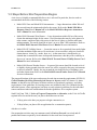
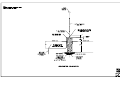
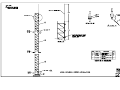
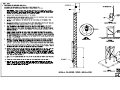
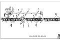
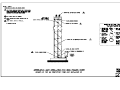
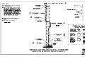
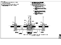
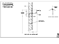
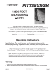
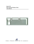
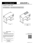
Automated Weather Observing System
AWOS III & AWOS III P
Site Preparation Manual
×
3000-3-025
FAA APPROVED
ECP180 — 2011 May 5
NOT FAA APPROVED
Rev. A
All Weather Inc. • 1165 National Drive • Sacramento, CA 95834 • USA • 800.824.5873 • www.allweatherinc.com
Copyright © 201, All Weather, Inc.
All Rights Reserved. The information contained herein is proprietary and is provided solely for the purpose of allowing customers to operate and/or service All Weather, Inc. manufactured equipment and is
not to be released, reproduced, or used for any other purpose without written permission of All
Weather, Inc.
Throughout this manual, trademarked names might be used. Rather than put a trademark (™) symbol in
every occurrence of a trademarked name, we state herein that we are using the names only in an editorial
fashion and to the benefit of the trademark owner, and with no intention of infringement. All Weather,
Inc. and the All Weather, Inc. logo are trademarks of All Weather, Inc.
Disclaimer
The information and specifications described in this manual are subject to change without notice.
Latest Manual Version
For the latest version of this manual, see the Product Manuals page under Reference on our web site at
www.allweatherinc.com/.
All Weather, Inc.
1165 National Drive
Sacramento, CA 95834
Tel.: (916) 928-1000
Fax: (916) 928-1165
Contact Customer Service
•
Phone support is available from 8:00am - 4:30pm PST, Monday through Friday. Call 916-928-1000
and ask for “Service.”
•
Online support is available by filling out a request at www.allweatherinc.com/customer/support.html
•
E-mail your support request to support@allweatherinc.com
C O N T E N T S
AWOS 3000 SITE PREPARATION MANUAL
Table of Contents
1. GENERAL .......................................................................................................................................................................................... 1
1.1
Introduction ........................................................................................................................................................................... 1
1.2
Definitions ............................................................................................................................................................................. 1
1.3
Steps Before Site Preparation Begins .................................................................................................................................. 2
1.4
Requirements........................................................................................................................................................................ 3
1.5
Coordination with Airport Authorities ..................................................................................................................................... 3
2. SITE PREPARATION ......................................................................................................................................................................... 4
3. ELEVATION AND WIND DIRECTION BENCHMARKS .................................................................................................................... 5
4. HARDWARE INSTALLATION ........................................................................................................................................................... 6
4.1
Foundations .......................................................................................................................................................................... 6
4.2
Conduit, Trenching, and Lightning Protection ....................................................................................................................... 7
4.3
Utility Services ...................................................................................................................................................................... 8
4.4
Tower Installation .................................................................................................................................................................. 8
4.5
Central Data Platform (CDP) ................................................................................................................................................ 9
5. SITE CLEANUP AND RESTORATION............................................................................................................................................ 11
6. TESTS AND INSPECTIONS ............................................................................................................................................................ 12
7. COORDINATION .............................................................................................................................................................................. 13
8. MATERIALS LIST ............................................................................................................................................................................ 14
9. ANTENNA MOUNTING MATERIALS LIST ..................................................................................................................................... 15
10. DRAWINGS .................................................................................................................................................................................... 16
G E N E R A L
1
Chapter
General
1.1 Introduction
This manual is designed to assist a contractor retained to prepare a site for an Automated
Weather Observing System (AWOS). Site preparation includes not only the actual physical
work, but permits, licenses, and coordination with airport authorities. This document provides
details for concrete, towers, conduit and underground lightning protection.
The actual installation of sensors and equipment described in the AWOS 3000 Installation and
Checkout Manual (3000-017) will be performed by or under the direction of All Weather, Inc.
There are several different AWOS 3000 systems that differ in the sensors that are installed.
There is a Site Preparation Manual is specific to each AWOS 3000 system category, so you will
need to refer to the correct Site Preparation manual for the system category you are installing.
The different AWOS system categories are listed below.
AWOS A
AWOS I
AWOS II
AWOS A-V
AWOS SYSTEM CATEGORIES
AWOS III
AWOS III T
AWOS III P/T/Z
AWOS III P AWOS III P/T
PLATFORM ELEVATED
All drawing references refer to the drawings at the back of this manual. Each drawing sheet is
labeled with a text caption. These captions will be used within this document to identify the relevant sheet(s).
1.2 Definitions
As used herein, the term contractor refers to the site preparation contractor who has been
assigned responsibility for all site survey and preparation tasks.
The term manufacturer refers to All Weather Inc., who will provide and install the AWOS
hardware.
1
AWOS 3000 SITE PREPARATION MANUAL
G E N E R A L
1.3 Steps Before Site Preparation Begins
A site survey is highly recommended before a site is selected. In particular, the site needs to
accommodate the needs of the following sensors.
•
Model 2020 Vane and Model 2030 Anemometer — Large obstructions within 300 m of
the sensor dictate the minimum height for the sensor. Refer to the Model 2020 Micro
Response Vane User’s Manual and to the Model 200 Micro Response Anemometer
User’s Manual for more information.
•
Model 2040 Ultrasonic Wind Sensor — Large obstructions within 300 m of the sensor
dictate the minimum height for the sensor. Avoid locations that may be in the plane of a
radar scanner, and do not place this sensor in the line of sight to a satellite radio transmitting antenna. The sensor should be at least 1 m away from VHF transmitters. Refer to
the Model 2040 Ultrasonic Wind Sensor User’s Manual for more information.
•
Model 8364-E Visibility Sensor — Locate the sensor as far as practical from strobe lights
and other modulated light sources. Do not locate it in an area that is subject to localized
obstructions to vision (e.g., smoke, dust, etc.). At the same time, it should not be so
isolated that it cannot detect more widespread obstructions when they affect visibility in
the area of concern. Refer to the Model 8364-E Forward Scatter Visibility Sensor User’s
Manual for more information.
•
Model 6490 Present Weather Sensor — In general, the sensor should be located on level
or slightly sloping ground where the sensor site will be exposed to the same environment
as the area around it. Ideally, the area around the site should be free of buildings, trees,
and other obstructions. Refer to the Model 6490 Present Weather Sensor User’s Manual
for more information.
The proposed locations of the tower and sensors also take into account the requirements of FCM-S4,
Federal Standard for Siting Meteorological Sensors at Airports, and ICAO Annex 14, Aerodromes, so that the tower and sensor locations conform to operational, regulatory, and safety
requirements. Some guidelines for locating sensors are included in the User’s Manuals for the
individual sensors, where appropriate, but these are only technical guidelines for the individual
sensors and do not take into consideration the broader guidelines for a complete system.
Send FAA Form 7460-1, Notice of Proposed Construction or Alteration, to the FAA Air Traffic
regional office located in the area you plan to build the tower at least
•
30 days prior to the date you propose to begin construction, or
•
30 days before you plan to file an application for a construction permit,
whichever is earlier.
Site preparation activities may not commence until a Notice to Proceed is received and all
permits and licenses required by local authorities for the work have been procured.
2
AWOS 3000 SITE PREPARATION MANUAL
G E N E R A L
1.4 Requirements
Site preparation consists of all functional responsibilities from coordination with airport authorities to the installation of the wind tower, foundations, conduits, and other physical preparations
for the AWOS.
NOTE: NATIONAL AND LOCAL CODES SHALL HAVE PRECEDENCE OVER ANY
INSTRUCTION OR DETAIL IN THIS DOCUMENT.
1.5 Coordination with Airport Authorities
The Airport will furnish the contractor with information relative to the facility. As available, this
information will include equipment layout drawings, aerial photographs, coverage charts, obstruction plots, contour maps, existing termination points for commercial power and communications systems, and plot plans delineating proposed construction. Specific manufacturer’s data
is included in this document.
Coordination with airport authorities will address locations of power and communication termination for the remote site as well as the central site. Coordination with airport authorities should
also include site access procedures and site contact information for use during site preparation
and system installation.
3
S I T E
P R E P A R A T I O N
2
Chapter
Site Preparation
Once a Notice to Proceed is received and all permits and licenses required by local authorities
for the work have been procured, the contractor shall perform the following site preparation
work.
1. Perform clearing, grading, excavation, filling and backfilling.
2. Provide all concrete work (tower base, sensor foundation pads, etc.)
3. Install the 30' tower with obstruction lights and lightning rod.
4. If applicable, provide and install a data cable from the 30' tower to the central data
processing computer.
5. Provide and install an underground power run to the AWOS sensor site, terminating in
(as required) junction box(es), disconnect box, transformer, duplex outlet, and a circuit
breaker panel next to the tower.
6. Provide and install all below grade grounding for lightning protection for the AWOS
system.
7. Provide and install the conduits between the 30' tower and junction boxes at the sensor
foundations. Refer to the Site Layout, Trenching and Grounding and Electrical Conduit
drawings.
8. Install and energize the tower lights (see the Tower Lighting Installation drawings).
9. Provide and install antenna masts.
The tower, obstructions lights, lightning rod, VHF radio mast, and optional tower-mounted UHF
radio masts are either provided by All Weather, Inc. or are procured by the airport authority. All
other materials required to perform the site preparation instructions listed are provided by the site
preparation contractor. The Material List in Chapter 8 describes the materials required to do the
site preparation work.
4
E L E V A T I O N
A N D
W I N D
D I R E C T I O N
B E N C H M A R K S
3
Chapter
Elevation and Wind Direction Benchmarks
A surveyor should be retained to locate the North benchmark.
A wind direction reference point must be established in one of the four cardinal directions to
align the wind direction sensor. It is simplest to use True North as the reference, though at some
installations this may not be feasible. The reference point should be established relative to the
center of the AWOS tower. The following instructions explain how to locate a North benchmark.
Any of the other three directions can be determined once True North has been established.
True North uses the earth's geographic meridians, while Magnetic North is the North indicated
by a magnetic compass. Depending on a site's location, Magnetic North is to either the East or
West of True North (with the exception of sites along the "line of zero declination", where
Magnetic and True North are the same). This difference, measured in degrees, between True
North and Magnetic North is known as the magnetic declination. For sites west of the line of
zero declination (which runs roughly from west of Hudson Bay, down along Lake Michigan to
the Gulf Coast in western Florida), the magnetic declination is "Easterly". For sites east of the
zero line, the declination is "Westerly". The magnetic declination for a particular site can be
obtained from the site survey data form, airport directory, or from a U.S. Geological Survey map.
Use a surveying compass with telescope that can provide a measurement accurate to within 1° to
determine True North at the installation site.
Once True North has been established, use the surveying compass to determine the location at
which the benchmark will be installed. Install the benchmark approximately 100 feet from the
tower, and note the location in the log book.
The benchmark must be suitably protected from being buried, cut down, or destroyed during
normal maintenance of the area.
In addition to determining a wind direction benchmark, the barometric pressure sensor site elevation needs to be determined so that it can be factored into the altimeter calculations. The contractor doing the site preparation work does not have to do this directly since the information
may be determined from the site survey data form, airport directory, or from a U.S. Geological
Survey map.
5
H A R D W A R E
I N S T A L L A T I O N
4
Chapter
Hardware Installation
The hardware installation includes the construction of all foundations, placement of conduit,
erection of the tower, connection of the AC power distribution system, tower lights, and
lightning rod, and, for radio data link installations, installation of the antenna mast and antenna.
4.1 Foundations
Foundations described in this section apply to installations in the Continental U.S. where the
frost depth does not exceed 36 inches. Increase foundation depth accordingly where frost depths
may exceed 36 inches.
Two towers are available for use in AWOS installations, the Model 8509 Stacked Tower and the
Model 8518-A Foldover Tower. Where the drawing details are unique to a particular tower, the
tower type is identified on the drawing sheet.
4.1.1 Thirty-Foot Tower
Refer to the Tower Foundation drawing for tower foundation construction details.
Construct a 2×4 frame for the portion of the pad above ground surface. Locate foundation bolts
in the 2×4 frame as specified in the drawings for later use to secure a mounting frame for the
junction boxes, etc. The bottom of the hole should have a six-inch indentation that is filled with
compacted sand and gravel for drainage of the tower legs.
When all forms and wire mesh are installed and the tower base is in place (note: install the tower
base with the mounting holes up), pour the concrete, making sure that the tower is vertical to ±2
degrees. The concrete should be crowned slightly to allow water to runoff. When the concrete
has set, remove the 2×4 forms and backfill as required. Bevel all pad edges.
6
H A R D W A R E
AWOS 3000 SITE PREPARATION MANUAL
I N S T A L L A T I O N
4.1.2 Visibility Sensor Pad
The Model 8364-E Visibility Sensor mounts on a 2½" galvanized steel pipe (2.875 O.D.) that
extends about 8 feet above ground level. The bottom section of the two-piece mast is embedded
in the concrete for ease of installation. Refer to the Visibility Sensor Foundation drawing for
construction details. Make sure the mast is vertical to within ± 2 degrees. Bevel all pad edges.
All concrete pads should be crowned to keep rain from accumulating around the vertical pipe.
Also, it might be a good idea to cap this pipe temporarily if there will be much time between site
preparation and installation of the visibility sensor to keep rain from accumulating in the pipe.
4.1.3 Ceilometer Pad
The Model 8339 Ceilometer mounts on a 2½" galvanized steel pipe (2.875 O.D.) that extends
about 6 feet above ground level. The bottom section of the two-piece mast is embedded in the
concrete for ease of installation. Refer to the 8339 Ceilometer Foundation drawing for construction details. Make sure the mast is vertical to within ± 2 degrees. Bevel all pad edges.
All concrete pads should be crowned to keep rain from accumulating around the vertical pipe.
Also, it might be a good idea to cap this pipe temporarily if there will be much time between site
preparation and installation of the ceilometer to keep rain from accumulating in the pipe.
4.2 Conduit, Trenching, and Lightning Protection
All sensor locations will require signal, power, and lightning protection cables. The conduit,
trenching, and lightning protection details are specified in the drawings.
After the foundations are poured, excavate a trench from the incoming power source (and land
line communications cable, if applicable) to the 30' tower and from there to each of the foundation pads. Refer to the Site Layout, Trenching and Grounding drawings for trenching details.
All conduits and lightning protection cables will be installed in this trench. Install the 3/4" x 10'
L ground rod. To this ground rod, weld or clamp a #4/0 AWG ground wire for each foundation
pad, and any other ground wires that may be necessary. Route a cable to each pad in the most
direct method. Do not bend any of the ground cables in less than an 8" radius at any point in the
cable length, and do not bend any cable to an angle sharper that 90°. Connect each cable to the
point on the pad shown in the individual Sensor Foundation drawings using an M105656-00
lug. The lug is attached to the tower leg on either tower according to the Tower Installation
drawing. Before attaching the lug, remove paint by scraping or sanding to ensure a good electrical connection, as the tower itself will function as a lightning down conductor. Another cable
is attached by an M105656-00 lug to a bolt on the mast on the visibility pad. A lug is to be left
attached to the cable that comes out of the ground at the ceilometer pad, with the cable length
such as to reach the approximate center of the pad. The All Weather, Inc. engineer will connect
this when installing the sensors.
Note that all buried ground connections are to be exothermically welded to comply with
Advisory Circular 150/5220-16C, Section 34, with respect to lightning and surge protection.
7
H A R D W A R E
AWOS 3000 SITE PREPARATION MANUAL
I N S T A L L A T I O N
Install the power cables and conduit that supply power to the site to the equipment mounted on
the frame at the tower location (see Section 4.3). The frame details are defined in the drawings.
Place power conduits in the trench, and attach junction boxes or 90° condulets at the sensor
foundations. The ends at the tower connect to the circuit breaker cabinet. The junction boxes or
condulets at the sensor pads are supported by rigid conduit and straps attached to the foundation.
Install the signal conduits in the same manner, securing the ends at the tower to a junction box on
the frame. If applicable (land line sites), install the incoming communications conduit and cable
from the central data processing computer to a junction box next to the tower (see Section 4.3.2).
Place electrical wire of an appropriate size and type in the electrical conduits running from the
circuit breaker panel to junction boxes at the sensor pads.
Place 3/16" pull ropes in all signal conduits running between the tower and the sensor pads.
Backfill and compact the trench.
4.3 Utility Services
4.3.1 Input Power
The contractor shall provide and install the required AC input power (see the Power Requirements drawing) for use by the AWOS, connecting to an existing power source as determined
during the site survey.
Transformers, main disconnect boxes etc., if required, shall be provided in accordance with
ANSI-C57, 12.25-1981.
4.3.2 Communications
At airports designated as “land line” (as opposed to UHF/VHF radio data link), provide and
install a communications data cable as specified in the materials list from a junction box next to
the tower to the AWOS central data processing computer. The maximum length is 4,000 feet.
The cable should be either in a conduit for its full length, or of a type suitable for direct burial.
4.4 Tower Installation
Do not install towers near power lines. All towers should be installed by experienced and trained
personnel. All installations must be grounded per local and national codes. For sites with the
Model 8518-A Foldover Tower, care should be taken to site the tower so that the tower and
boom are clear of obstructions when folded over. See the 30' Foldover Tower Installation
drawing for clearance measurements.
The use of a climbing belt is mandatory for any person climbing the stacked tower.
Installation of the tower assumes completion of the foundation. The foundation concrete must be
adequately cured before tower installation. See the Tower Installation drawings for installation
details.
8
H A R D W A R E
AWOS 3000 SITE PREPARATION MANUAL
I N S T A L L A T I O N
4.4.1 Tower Lights
The tower lights must be installed immediately after erection of the tower. Refer to the Tower
Lighting Installation drawing for details.
4.4.2 Lightning Protection
Remove paint from the area under the lightning rod clamps, and install the lightning rod according to the Tower Installation drawing.
4.4.3 UHF/VHF Data Link Antenna Mast (Data Link Installations Only)
(See the Radio Data Link Antenna Mast drawing). Bend a piece of ¾" conduit (rigid or EMT)
as shown on the drawing. Locate the antenna mast on the side of the tower nearest the Central
Station Equipment. No obstructions may exist between the antenna on the tower and the antenna
located near the Central Station Equipment. A clear line-of-sight path is required. Use the
M488292-00 antenna mount to attach the antenna to the mast instead of the bracket provided
with the antenna.
The All Weather, Inc. engineer will install the antenna and the antenna cable.
4.5 Central Data Platform (CDP)
Place the CDP at an indoor location specified by the airport authority. The indoor space must
accommodate the 11RU equipment rack, which is 22" × 20.5" × 20", and weights about 150
pounds, including the UPS power supply. The location should take into account the need to
access the front and both sides of the rack.
4.5.1 Equipment
The CDP is mounted in an industrial-grade 11RU rack along with a UPS. The rack also houses
the VHF ground-to-air radio and the CDP options.
4.5.2 Temperature Requirements
The indoor equipment must be located in a conditioned space where the temperature is maintained between 40°F and 105°F, with a relative humidity between 5% and 90%.
4.5.3 Power Requirements
The indoor equipment must be located within three feet of an outlet with 120 V AC, 60 Hz
(± 5%). The indoor equipment requires 500 V·A and should be on a dedicated 15 A circuit.
4.5.4 Telephone Requirements
The indoor equipment must be located with access to a telephone line terminated with an RJ-11
connector. The phone line is dedicated to the AWOS modem and must not be shared with other
telephones, FAX machines, etc.
9
H A R D W A R E
AWOS 3000 SITE PREPARATION MANUAL
I N S T A L L A T I O N
4.5.5 VHF Voice Radio Antenna Mast
The VHF radio antenna (supplied and installed by All Weather, Inc.) will be located outdoors
and away from obstructions. The antenna should not be mounted within 100' of other radio
transmitters, such as a UNICOM transmitter. If such a location is not available for the radio
mast, contact All Weather Inc. for further instructions. This antenna is usually mounted on the
roof of a building; however other mounting configurations are available (see the Central Station
Antenna Mast Options drawing). The mast should be at least 5' in length. Install the desired
antenna mount and mast.
The VHF radio antenna and cable will be installed by the All Weather Inc. engineer.
4.5.6 UHF/VHF Data Link Radio Antenna Mast (Data Link Installations Only)
The UHF/VHF Data Link Radio Antenna (supplied by All Weather Inc.) must be located outdoors and away from obstructions. This antenna is usually mounted on the roof of a building;
however other mounting configurations are available (see the Central Station Antenna Mast
Options drawing). The antenna mast should be at least 5' in length. This antenna should be
mounted at least 20' away from the VHF Voice Radio Antenna. Install the desired antenna mount
and mast.
The All Weather, Inc. engineer will install the antenna and antenna cable.
4.5.7 AWOS Net (optional)
Some AWOS systems use the optional AWOS Net. The AWOS Net can be used as a Web server
and/or to support a remote display. There are three types of AWOS Net, each based on the communication protocol used by the AWOS Net.
4.5.7.1 RS-232 AWOS Net
No additional site preparation work is needed for this AWOS Net type.
4.5.7.2 RS-485 AWOS Net
No additional site preparation work is needed for this AWOS Net type.
4.5.7.3 UHF Radio AWOS Net
The UHF radio AWOS Net is used when the AWOS Net cannot be hard-wired to the CDP or is
more than 4000 feet from the CDP. The CDP must be communicating with the DCP using a
UHF radio for this AWOS Net option to be used.
An antenna mount like the VHF antenna mount described in Section 4.5.5 must be installed on
the roof of the building or some other appropriate location within the line of sight to the CDP
UHF radio antenna. The AWOS Net device uses the same frequency as the DCP–CDP UHF
radio link
Install the antenna mount and mast (see the Central Station Antenna Mast Options drawing).
The mast should be at least 5' in length.
The UHF radio antenna and cable will be installed by the All Weather Inc. engineer.
10
S I T E
C L E A N U P
A N D
R E S T O R A T I O N
5
Chapter
Site Cleanup and Restoration
Site cleanup and restoration shall include the following:
1. Removal of all contractor-furnished material, tools and equipment that will not become
airport property upon acceptance of site work.
2. Removal of all trash, litter, packing, and excess material from the site, to be disposed of
by the contractor.
3. Restoration of previously existing access roads, parking areas, building exterior or other
portions of the site inadvertently damaged by the contractor so as to be returned to the
same condition as existed before beginning work at the site.
4. Optionally, fill site with gravel or crushed rock for drainage and control of vegetation.
5. Upon completion of the site cleanup and restoration, the contractor shall obtain a written
release from the property owner attesting that the sites have been restored to a satisfactory condition.
11
T E S T S
A N D
I N S P E C T I O N S
6
Chapter
Tests and Inspections
The contractor is responsible for securing all necessary construction and electrical permits,
waivers, etc., before commencing work. After completion of the work, the contractor shall demonstrate acceptable work to the airport owner, manager, or other authority as appropriate. It is the
responsibility of the contractor that all aspects of this project that are under his control are in
conformance with appropriate building and electrical codes. Nothing in this document shall
preclude any requirement for code conformance.
As early as possible, the contractor shall notify All Weather Inc. of the date when the site will be
ready for installation of the AWOS system. The contractor is required to provide digital photographs showing that all required work has been completed and that the equipment is at the site.
All Weather, Inc. will not schedule an FSE (Field Service Engineer) for installation until these
photographs have been submitted and reviewed to ensure the site is ready for installation. The
contractor may also be required to provide a signed document attesting that all required work has
been completed and that all equipment and material have been installed in accordance with the
appropriate manuals and specifications, applicable building codes, and accepted engineering
practices; that the tower lights are operational; that circuit breakers are available in the disconnect box; that pull ropes are in the signal conduits; that all towers and pads are leveled properly;
and that the communication line to the central station is in place.
To assure that the site is completely ready for delivery and installation of AWOS equipment, the
airport may invite the AWOS equipment vendor to participate in the acceptance inspection. The
contractor shall correct all deficiencies detected during the inspection prior to the airport acceptance of site work. Facilities that give evidence of substandard contractor performance will not
be accepted by the airport.
When All Weather Inc. is notified of completion as described above, if any part of the site preparation described in this document has not been accomplished and extra costs are incurred as a
result of such deficiency, the contractor may be required to reimburse All Weather Inc. for such
actual excess costs.
12
C O O R D I N A T I O N
7
Chapter
Coordination
The contractor shall perform all work in a manner that does not conflict with or adversely affect
the air traffic operational environment. In the event of any actual or potential conflict, air traffic
activities shall have priority over all contractor activities. The contractor shall provide services in
a manner and at such times as will not disrupt the normal flow of air traffic.
13
M A T E R I A L S
L I S T
8
Chapter
Materials List
All Weather Inc. shall supply the tower and the tower light fixture. The site preparation contractor shall provide the remaining materials as listed in the Material List in drawing 3000-3-007.
14
A N T E N N A
M O U N T I N G
M A T E R I A L S
L I S T
9
Chapter
Antenna Mounting Materials List
The following table lists the material requirements for antennas installed as part of the Central
Station equipment.
All sites require one antenna at the Central Station for VHF radio voice output. Sites using UHF
data links require two antennas at the Central Station, along with mounting hardware and masts.
Select one mounting option from the table for each antenna. Figures showing antenna assembly
procedures and the various mounting options are included at the back of the Drawings section of
this manual.
Antennas and Antenna Mounting Materials List
Quantity
1* or 2** or more***
* (voice only)
** (voice and data link)
***(one more for each
UHF Radio AWOS Net)
Select 1 mounting
option for each antenna
Description
Part No. (or equiv.)
Antenna mast, 1-1/4" x 5' or 1-1/4" x 10'
Radio Shack 15-842 (5')
Radio Shack 15-843 (10')
GC Electronics 32-9013 (5')
GC Electronics 32-9014 (10')
Base and roof mount
Radio Shack 15-889
Vent pipe mount
Radio Shack 15-893
GC Electronics 8802
"12"" wall mounts"
Radio Shack 15-885
GC Electronics 8312
"4"" wall mounts"
Radio Shack 15-883
GC Electronics 8304
Eaves mount
Radio Shack 15-891
3' tripod mount
Radio Shack 15-516
GC Electronics 9160
Antenna and antenna cables supplied by All Weather Inc.
15
D R A W I N G S
10
Chapter
Drawings
The following pages contain drawings detailing site preparation activities.
3000-3-007
—
Site Layout, Trenching, and Grounding
UHF/VHF Antenna Assembly
16
This antenna is supplied to operate satisfactorily within the frequency range(s) specified
on the carton label. Some models require
cutting of radiator and/or radials in accordance with Figure 11. If the antenna is to be
used over a range of frequencies, the element
lengths should be chosen for mid-range or
favor the element length for the most used, or
the frequency requiring the greatest range.
ASSEMBLING THE ANTENNA
1) Select antenna location and route cable
from set to antenna.
2) Loosen mounting nut and assemble radials
to hub as shown in illustration. Tighten jam
nuts and lockwashers against hub to
secure the radials. Retighten mounting nut.
3) Connect cable to antenna (accepts PL-259).
Some models are supplied with cable and
connector for the antenna end. Radio end
connector is not supplied.
4) Mount antenna onto 1/2"-3/4" pipe, or up to
1-3/8" O.D. tubing (not supplied) with Ubolt, lockwashers and hex nuts provided.
5) Secure cable to mounting pipe with straps
or plastic tape to avoid strain on cable
connections.
The use of a PTFE or similar lubricant on the
threaded portions of the antenna prior to
assembly will provide protection from
weather and ease future disassembly.
UHF/VHF Antenna Assembly
Lengths on chart are approximate. For finer tuning, use a
VSWR bridge if antenna is to be
used for transmitting.
Remove vinyl cap before measuring and cutting. Slide vinyl cap
back on after cutting.
UHF/VHF Antenna Assembly (cont.)
Base and Roof Mount.
Heavy-gauge steel
swivel base fits the
slope of most roofs. 1¼"
mast locks into U-bolt.
Radio Shack P/N 15-889
Vent Pipe Mount.
Brackets attach to 2" to
5" vent pipes (GC
model fits 2" to 4" vents).
1¼" mast clamps into
place.
Radio Shack P/N 15-893
GC Electronics P/N
8802
12" Wall Mounts.
Secures 1¼" mast 12"
from side of building.
Radio Shack P/N 15-885
GC Electronics P/N
8312
4" Wall Mounts.
Secures 1¼" mast 4"
from side of building.
Radio Shack P/N 15-883
GC Electronics P/N
8304
Eaves Mount.
Secures 1¼" mast to
hanging rafters or trim
boards; fits most medium-pitch roofs. Includes 4 lag bolts.
Radio Shack P/N 15-891
3' Tripod Mount.
Designed for larger
antennas and areas
subject to strong winds.
Fits slope of most roofs.
Fits 1¼" mast.
Radio Shack P/N 15-516
GC Electronics P/N
9160
Masts:
Use with 1¼" diameter 5' steel mast (Radio Shack P/N 15-842, GC Electronics P/N 32-9013)
or 10' steel mast (Radio Shack P/N 15-843, GC Electronics P/N 32-9014).
Central Station Antenna Mast Options
All Weather Inc.
1165 National Drive
Sacramento, CA 95818
Fax: 916.928.1165
Phone: 916.928.1000
Toll Free: 800.824.5873
3000-3-025
Revision A
March, 2011